
Owner's Manual
JCRHFTSMIIH°J
20.0 HP
ELECTRIC START
48" MOWER
AUTOMATIC
LAWN TRACTOR
Model No.
917.272241
• Safety
• Assembly
• Operation
• Maintenance
• Repair Parts
CAUTION:
Read and follow all
Safety Rules and Instructions
before operating this equip-
ment.
For answers to your questions
about this product, Call:
1-800-659-5917
Sears Craftsman Help Line
5 am - 5 pm, Mon- Sat
Sears, Roebuck and Co., Hoffman Estates, IL 60179
Visit our Craftsman website: www,sears.com/craftsman
Warranty ............................................... 2
Safety Rules ......................................... 3
Product Specifications .......................... 6
Assembly .............................................. 8
Operation ............................................ 12
Maintenance Schedule ...................... 18
Maintenance ....................................... 18
Service and Adjustments .................... 22
Storage ............................................... 29
Troubleshooting ................................. 30
Repair Parts........................................ 34
Parts Ordering ..................... Back Cover
LIMITED'FWO YEAR WARRANTY ON CRAFTSMAN RIDING EQUIPMENT PARTS
For two (2) years from the date of purchase, if this Craftsman Riding Equipment is
maintained, lubricated and tuned up according to the instructionsin the owner's
manual, Sears will repair or replace, free of charge, any parts found to be defective in
matedal or workmanship. Warranty service is available free of charge by returning
your Craftsman riding equipment to your nearest Sears Service Center. In-home
warranty service is available but a trip charge willapply. This warranty applies only
while this product is in the United States.
ThisWarranty does not cover:
• Expendable items which become worn during normal use, such as blades, spark
plugs, air cleaners, belts and oil filters.
• Tire replacement or repair caused by punctures from outside objects, such as nails,
thorns, stumps, or glass.
• Repairs necessary because of operator abuse, including but not limitedto, damage
caused by towing objects beyond the capability of the dding equipment, impacting
objects that bend the frame or crankshaft, or over speeding the engine.
• Repairs necessary because of operator negligence, including but not limited to,
electdcal and mechanical damage caused by improper storage, failure to use the
proper grade and amount of engine oil,failure to keep the deck clear of flammable
debds, or the failure to maintain the equipment according to the instructions
contained in the owner's manual.
• Engine (fuel system) cleaning or repairs caused by fuel determined to be contami-
nated or oxidized (stale). In general, fuel should be used within thirty(30) days of its
purchase date.
• Riding equipment used for commercial or rental purposes. A product is =used for
commercial purpose" if is used for any purpose other than singlefamily household
dwellingsor in usage where profit is made.
LIMITED 90 DAYWARRANTY ON BATTERY
For ninety (90) days from date of purchase, if any battery included with this dding
equipment proves defective in rnatedal or workmanship and our testing determines
the battery will not hold a charge, Sears will replace the battery at no charge. War-
ranty service is available free of charge by returning your Craftsman dding equipment
to your nearest Sears Service Center. In-home warranty service is available but a trip
charge will apply. This warranty applies only while this product is in the United States.
TO LOCATE THE NEAREST SEARS SERVICE CENTER ORTO SCHEDULE IN-
HOME WARRANTY SERVICE, SIMPLY CONTACT SEARS AT 1-800-4-MY-HOME
This Warranty gives you specific legal dghts, and you may also have other dghts
which may vary from state to state.
Sears, Roebuck and Co., D/817 WA, Hoffman Estates, IL 60179
IMPORTANT:Thiscuttingmachineiscapableofamputatinghandsand feet and
throwing,objects. Failure to observe the followingsafety instructionscould result in
sedous injury or death.
I. GENERAL OPERATION
• Read, understand,arid follow all
instructions in the manual and on the
machine beforestarting.
• Only allow responsibleadults,who are
familiarwith the instructions,to operate
the machine.
• Clear the area of objectssuch as rocks,
toys,wire, etc., whichcould be picked
up and thrownby the blade.
• Be sure the area isclear of other people
before mowing. Stop machine if anyone
enters the area.
• Never carry passengers.
• Do net mow in reverse unlessabsolutely
necessary. Alwaysleek down and
behind before and while backing.
• Be aware of the mower discharge
directionand do net point it at anyone.
Do notoperate the mowerwithout either
the entire grosscatcher or the guard in
place,
• Slowdown before tuming.
• Never leave a running machine
unattended. Alwaysturnoff blades,set
parking brake, stop engine, and remove
keys before dismounting.
• Turn off blades when net mowing.
• Stop engine before removinggrass
catcher or uncloggingchute.
• Mow only in daylightor good artificial
light.
• Do net operate the machine while under
the influenceof alcoholor drugs.
• Watch for trafficwhen operatingnear or
crossing roadways.
• Use extra care when loading or unload-
ingthe machine intoa bailer ortruck.
• Data indicatesthat operators,age 60
years and above, are involved in a large
percentage of riding mower-related
injuries. These operators should
evaluate their abilityto operate the riding
mower safely enough to protecttbem-
selves and othersfrom serious injury.
• Keep machine fl'eeof grass, leaves or
other debris build-upwhichcan touch
bet exhaust/ engine partsand bum. Do
net allow the mower deck to plow leaves
or other debris which can cause build-
up tooccur. Clean any oilor fuel
spillagebefore operating or storingthe
machine. Allow machine to cool before
storage.
I1.SLOPE OPERATION
Slopes are a majorfactor related toloss--of-
control arid tipoveraccidents,whichcan re-
suit in severe injury or death. All slopes
requireextra caution, ffyou cannotback up
the slope or if you feel uneasyon it, do not
mow it.
DO:
• Mow upand down slopes, net across.
• Remove obstaclessuch as rocks,tree
limbs,etc.
Watch for holes,ruts,or bumps. Uneven
terrain couldovertum the machine. Ta//
grass can hideobstacles.
Use slew speed. Choose a low gear so
that youwill not have to stopor shift
while on the slope.
Follow the manufacturer's recommenda-
tions for wheel weights or counter-
weights to improvestability.
Use extra care with grasscatchersor
other attachments. These can change
the stabilityof the machine.
Keep all movement on the slopes slow
and gradual Do notmake sudden
changes in speed or direction.
Avoid startingor stoppingon a dope. ff
tireslose traction, disengage the blades
and proceed slowly straight downthe
slope.
DO NOT:
• Do not rum on slopes unless necessary,
and then, turnslowly and gradually
downhill, if possible.
• Do notmow near drop-offs,ditches,or
embankments. The mower could
suddenlyturnover if a wheel is over the
edge of a cliffor ditch,or ifan edge
caves in.
• Do notmow on wet grass. Reduced
traction could cause sliding.
• Do not try to stabilizethe machine by
patting your foot onthe ground.
• Do notuse grasscatcher on steep
slopes.
3
ttt. CHILDREN
Tragic accidents con occur if the operator
is not alert to the presence ofchildren.
Childrenare often attracted to the
machine and the mowing activity. Never
assume that children will remain where
you last saw them.
• Keep children out of the mowing area
and under the watchful core of another
responsible adult.
• Be alert and turn machine off if children
enterthe area,
• Before and when backing, look behind
and down for small children.
• Never carry children. They may fall off
and be seriously injured or interfere
with safe machine operation.
• Never allow children to operate the
machine.
• Use extra core when approaching blind
comers, shrubs, trees, or other objects
that may obscure vision.
IV. SERVICE
• Use extra core in handling gasoline
and other fuels. They are flammable
and vapors are explosive.
-Use only an approved container.
-Never remove gas cap or add fuel
with the engine running. Allow
engine to cool before refueling. Do
not smoke.
-Never refuel the machine indoors.
-Never store the machine or fuel
container inside where there is an
open flame, such as a water heater.
• Never run a machine inside a close_
area.
• Keep nutsand bolts, especially blac
attachment bolts, tight and keep
equipment in good condition.
• Never tamper with safety devices.
Check their proper operation regula
• Keep machine free of grass, leaves,
other debris build-up. Clean oil or fL
spillage. Allow machine to cool bef¢
stodng.
• Stop and inspect the equipment if y_
strike an object. Repair, if necessar
before restarting.
• Never make adjustments or repairs
with the engine running.
• Grass catcher components are subj
to wear, damage, and deterioration,
which could expose moving parts o=
allow objects to be thrown, Frequel
check components and replace wilt
manufacturer's recommended parts
when necessary.
• Mower blades are sharp and con ct
Wrap the blade(s) or wear gloves, _.
use extra caution when servicingth{
• Check brake operation frequently.
Adjust and service as required.
• Be sure the area isclear of other
peopta before mowing. Stop machine if
anyone enters the area.
• Never carry passengers or children
even with the blades off.
• Do not mow In reverse unless abso-
lutely necessary. Always look down
and behind before andwhile backing.
• Never carry children. They may fall off
and be seriously injured or interfere
with safe machine operation.
• Keep children out of the mowing area
and under the watchful care of another
responsible adult.
• Be alert and tam machine off if chik
enter the area.
• Before and when backing, lookbeP
and down for small children.
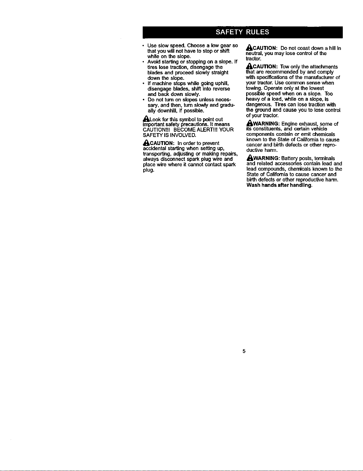
• Mow up and down slopes (15 ° Max
net across.
• Remove obstacles such as rocks, b
limbs,etc.
• Watch forholes, ruts, or bumps.
Uneven terrain could over_urnthe
machine. Tall grass can hide obsta
4
• Use slow speed. Choose a low gear so
thatyou willnot have to stopor shift
while on the slope,
• Avoid starting or stoppingon a slope. If
tires lose traction,disengage the
blades and proceed slowlystraight
down the slope.
• If machine stops while going uphill,
disengage blades, shiftinto reverse
and back down slowly.
• Do not turn on slopes unless neces-
saw, and then, turn slowlyand gradu-
ally downhill, if possible.
_Look for this symbol to pointout
importantsafety precautions.It means
CAUTIONI!! BECOMEALERT!!I YOUR
SAFETY IS INVOLVED.
_CAUTION: Inorder to prevent
accidental starting when setting up,
transporting, adjusting or making repairs,
always disconnect spark plug wire and
place wire where it cannot contact spark
plug.
,_kCAUTION: Do not coast down a hill in
neutral, you may lose control of the
tractor.
,_CAUTION: Towonlythe attachments
that are recommended by and comply
with specificationsof the manufacturer of
your tractor. Use common sense when
towing. Operate only at the lowest
possiblespeed when on a slope. Too
heavy of a load, while on a slope, is
dangerous. Tires can lose traction with
the ground and cause you to lose control
ofyour tractor.
_WARNING: Engine exhaust, some of
its constituents, and certain vehicle
components contain or emit chemicals
known to the State of California tocause
cancer and birthdefects or other repro-
ductive harm.
_WARNING: Battery pests, terminals
and related accessodes contain lead and
lead compounds, chemicals known to the
State of California to cause cancer and
birthdefects or other reproductiveharm.
Wash hands after handling,
5
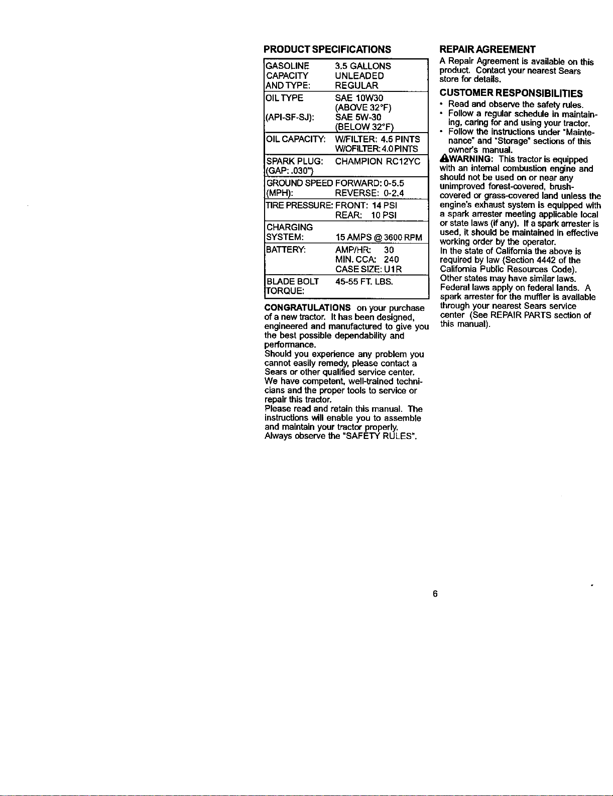
PRODUCTSPECIFICATIONS
GASOLINE 3.5GALLONS
CAPACITY UNLEADED
ANDTYPE: REGULAR
OIL TYPE SAE 10W30
(ABOVE 32°F)
API-SF-SJ): SAE 5W-30
(BELOW 32°F)
OIL CAPACITY: W/FILTER: 4.5 PINTS
W/OFILTER:4.0 PIhITS
SPARK PLUG: CHAMPION RC12YC
GAP: .030")
GROUND SPEED FORWARD: 0-5.5
(MPH): REVERSE: 0-2.4
TIRE PRESSURE: FRONT: 14 PSI
REAR: 10 PSI
CHARGING
SYSTEM: 15 AMPS @ 3600 RPM
BATTERY: AMP/HR: 30
MIN. CCA: 240
CASE SIZE: U1 R
BLADE BOLT 45-55 FT. LBS.
TORQUE:
CONGRATULATIONS on your purchase
ofa new tractor. Ithas been designed,
engineered and manufactured to give you
the best possible dependability and
performance.
Should you expedence any problem you
cannot easily remedy, please contact a
Sears or other qualified service center.
We have competent, well-trained techni-
cians and the proper tools to service or
repair thistractor.
Please read and retain this manual. The
instructionswill enable you to assemble
and maintain yourtractor properly.
Always observe the =SAFETY RULES".
REPAIRAGREEMENT
A Repair Agreement is available on this
product. Contactyour nearest Sears
store fordetails.
CUSTOMER RESPONSIBILITIES
• Read and observe the safety rules.
• Follow a regular schedule in maintain-
ing, caring for and using your tractor.
• Follow the instructionsunder "Mainte-
nanco" and "Storage" sections of this
owner's manual.
_iLWARNING: This tractor is equipped
with an internal combustionengine and
should notbe used on or near any
unimproved forest-covered, brush-
covered or grass-cevered land unless the
engine's exhaust system is equipped with
a spark arrester meeting applicable local
or state laws (if any). If a spark an'ester is
used, it should be maintained in effective
working order by the operator.
In the state of California the above is
required by law (Section 4442 of the
California Public Resoumes Code).
Other states may have similar laws.
Federal laws apply on federal lands. A
spark arrester for the muffler is available
through your nearest Sears service
center (See REPAIR PARTS section of
this manual).
6
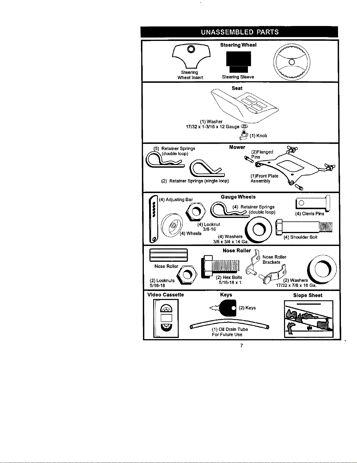
Steering
Wheel insert
Steering Wheel
SteeringSleeve
Seat
(1) Washer
17/32 x 1-3/16 x 12 Gauge
_(1) Knob
Mower
Retainer Springs
)
(2) Retainer Springs (single loop)
(2)Flanged _:_
(1)Front Plate _ " _
10/%,
(4) Adjusting Bar Gauge Wheels i-O_
_ (4) Retainer Springs (_
_ _ y __(double loop)
) ) Washers (4) Shoulder Bolt
3/8 x 3/4 x 14 Gm
L J Nose Roller_
L J _ _'#_ Nose Roller
Nose Roller_ _(2(2) Hex Bolts
(2) Locknuts _ 5/tR-1R x t ) Washer
5/16-18 ......... 17/32 x 7/8 x 16 GaW
Video Cassette
Keys
12) Keys
For Future Use
Slope Sheet
7
Yournewtractorhasbeenassembledatthefactorywithexceptionofthose parts left
unassembled for shipping purposes. Toensure safe and proper operation of your
tractor all parts and hardware you assemble must be tightened securely.Use the
correct tools as necessary to insure proper tightness.Review the video cassette before
you begin.
TOOLS REQUIRED FOR ASSEMBLY
A socket wrench set will make assembly
easier. Standard wrench sizes you need
are listed below.
(2) 9/16" wrench (1) 3/4" Socket w/
(1) 1/2" wrench drive ratchet
(1) Utility knife (1) Pliers
(1) Tire pressure gauge
When dght or left hand is mentioned in
this manual, it means, from your pointof
view, when you are in the operating
position(seated behind the steering
wheel).
TO REMOVETRACTOR FROM
CARTON
UNPACK CARTON
1. Remove all accessible loose parts
and parts cartons from carton.
2. Cut, from top to bottom, along lines on
all four comers of carton, and lay
panels fiat.
3. Remove mower and packing materi-
als.
4. Check for any additional loose parts
or cartons and remove.
BEFORE REMOVING TRACTOR
FROM SKID
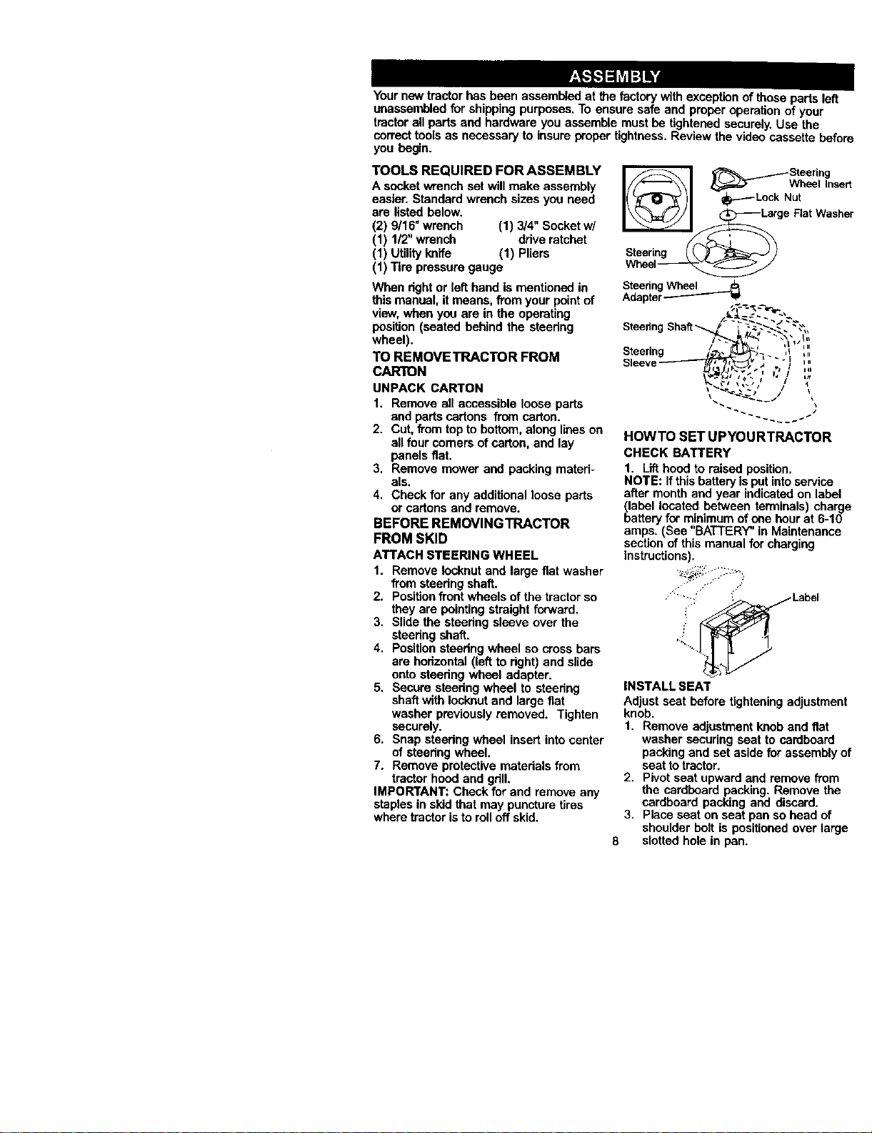
ATTACH STEERING WHEEL
1. Remove Iocknut and large fiat washer
from steering shaft.
2. Positionfront wheels ofthe tractor so
they are pointing straight forward.
3. Slide the steedng sleeve over the
steedng shaft.
4. Positionsteedng wheel so cross bars
are horizontal (left to right) and slide
onto steedng wheel adapter.
5. Secure steedng wheel to steedng
shaft with Iocknut and large fiat
washer previously removed. Tighten
securely.
6. Snap steering wheel insert into center
of steedng wheel.
7. Remove protective materials from
tractor hood and grill.
IMPORTANT: Check for and remove any
staples in skid that may puncture tires
where tractor isto rolloff skid.
I( )1 - LockNut
__ge FlatWasher
Steering __ _ _)
Wheel_
SteeringWheel
Adapter------'-'-_ _lp
SteeringShaft_ / - - _-=_-_-__,-""",_':
Steerln _. .i ,,
Sleeve ,' _ _,÷ 1 '"
HOWTO SET UPYOURTRACTOR
CHECK BATTERY
1. Lift hood to raised position.
NOTE: If thisbattery isput intoservice
after month and year indicated on label
blabellocated between terminals) charge
artery for minimum ofone hour at 6-10
amps. (See "BATTERY" in Maintenance
section of this manual for charging
instructions).
"'"'-1::" '{" Label
INSTALl -qEAT
Adjust seat before tightening adjustment
knob.
1. Remove adjustment knob and fiat
washer securing seat to cardboard
packing and set aside for assembly of
seat to tractor.
2. Pivotseat upward and remove from
the cardboard packing. Remove the
cardboard packing and discard.
3. Place seat on seat pan so head of
shoulder bolt is positioned over large
8 slotted hole in pan.
4. Pushdownonseattoengage
shoulderbeltinslotandpullseat
towardsrearoftractor.
5. Pivotseat and pan forward and
assemble adjustment knob and fiat
washer loosely. Do not tighten.
6. Lower seat into operating position and
sit in seat.
7. Slide seat until a comfortable position
is reached which allows you to press
clutch/brake pedal all the way down.
8. Get offseat withoutmoving its
adjusted position.
9. Raise seat and tighten adjustment
knob securely.
Seat
SeatAdjustmen_tK_FPan __ BSh_ulder
NOTE: You may now rollor drive your
tractor off the skid. Follow the apprepdate
instructionbelowto remove the tractor
from the skid.
TO ROLLTRACTOR OFF SKID (See
Operation section for location and
function of controls)
1. Press liftlever plunger and raise
attachment liftlever to its highest
position.
2. Release parking brake by depressing
brake pedal.
3. Place freewheel control in freewheel-
ing positionto disengage transmis-
sion(See =TOTRANSPORT" inthe
Operation section of this manual).
4. Roll tractor forward off skid.
TO DRIVETRACTOR OFF SKID (See
Operation section for location and
function of controls)
_I_WARNING: Before starting,read,
understand and follow all instructionsin
the Operation section of this manual. Be
sure tractor is in a well-ventilated area. Be
sure the area in frontoftractor isclear of
other people and objects.
1. Be sure all the above assembly steps
have been completed.
2. Check e_gine oil level and fill fuel
tank with gasoline.
3. Place freewheel control in '_ransmis-
sion engaged" position.
4. Sit on seat in operating position,
depress brake pedal and set the
parking brake.
5. Press lift lever plungerand raise
attachment liftlever to its highest
position.
6. Start the engine. After engine has
started, move throttle controlto idle
position.
7. Release parking brake.
8. Slowly depress forward ddve pedal
and ddve tractor off skid.
9. Apply brake to stop tractor and set
parking brake.
10.Turn ignitionkey to "OFF" position.
Continue with the instructionsthat follow.
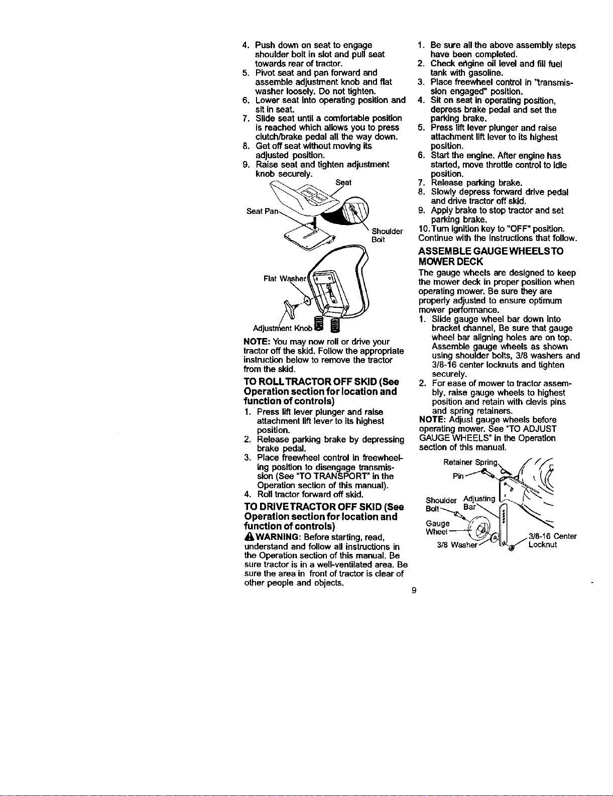
ASSEMBLE GAUGEWHEELSTO
MOWER DECK
The gauge wheels are designed to keep
the mower deck in proper positionwhen
operating mower. Be sure they are
propedy adjusted to ensure optimum
mower performance.
1. Slide gauge wheel bar down into
bracket channel, Be sure that gauge
wheel bar aligning holes are on top.
Assemble gauge wheels as shown
using shoulder belts, 3/8 washers and
3/8-16 center lecknuts and tighten
securely.
2, For ease of mower to tractor assem-
bly, raise gauge wheels to highest
positionand retain with clevis pins
and spdng retainers.
NOTE: Adjustgauge wheels before
operating mower. See "TO ADJUST
GAUGE WHEELS" in the Operation
section of this manual.
Pin-_
Shoulder _..
Bolt Bar
Ga__
3/8 Washerf v _ Locknut
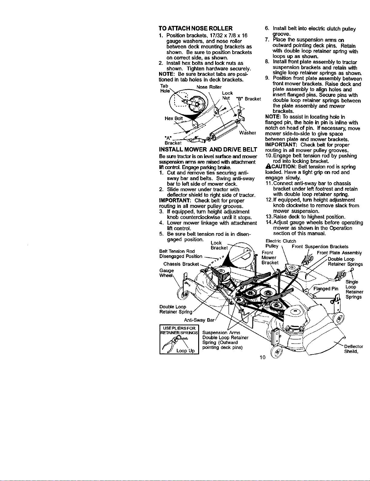
TOATTACHNOSEROLLER
1. Positionbrackets,17/32x7/8x16
gaugewashers,andnoseroller
betweendeckmountingbracketsas
shown.Besuretopositionbrackets
oncorrectside,asshown.
2. Installhexboltsandlocknutsas
shown.Tightenhardwaresecurely.
NOTE:Besurebrackettabsareposi-
tionedintabholesindeckbrackets.
Tab NoseRoller
Lock
"B"Bracket
Hex Bolt
Bracket
INSTALL MOWER AND DRIVE BELT
Be suretractorisonlevelsurfaceand mover
suspensionan-nsare raisedwithattachment
liftconlrnl.Engageparld'KJbrake.
1. Cut and remove ties secudng anti-
sway bar and belts. Swing anti-sway
bar to left side of mower deck.
2. Slide mower under tractor with
deflector shield to dght side of tractor.
IMPORTANT: Check belt for proper
routing in all mower pulley grooves.
3. If equipped, turn height adjustment
knob counterclockwise until it stops.
4. Lower mower linkage with attachment
liftcontrol.
5. Be sure belt tension red is in disen-
gaged position. Lock
Belt Tension Rod
Disengaged Position
Gauge
Wheel_
Double Loop
Retainer Spring
Anti-Swa)
USEPLIERSFOR
RL=TAINERSPRINGSSuspension Arms
/_L_p Double Loop Retainer
Spdng (Outward
Up pointing deck pins)
6. Install belt into electric dutch pulley
groove.
7. Place the suspension arms on
outward pointingdeck pins. Retain
with double loop retainer spdng with
loops up as shown.
8. Install front plate assembly totractor
suspension brackets and retain with
single loop retainer spdngs as shown.
9. Positionfront plate assembly between
front mower brackets. Raise deck and
plate assembly to align holes and
insert flanged pins. Secure pins with
double loop retainer spdngs between
the plate assembly and mower
brackets.
NOTE: To assistin locating holein
flanged pin, the hole in pin is inline with
notch on head ofpin. If necessary, move
mower side-to-side to give space
between plate and mower brackets.
IMPORTANT: Check belt forproper
routing in all mower pulley grooves.
10.Engage belt tension rod by pushing
red intolocking bracket.
A,CAUTION: Belt tensionrod is spring
loaded. Have a tight gdp on rod and
engage slowly.
11.Connect anti-sway bar to chassis
bracket under left footrestand retain
with double loop retainer spdng.
12.If equipped, turn height adjustment
knob clockwiseto remove slack from
mower suspension.
13. Raise deck to highest position.
14.Adjust gauge wheels before operating
mower as shown in the Operation
sectionof this manual.
Electric Clutch
Pulley Front Suspention Brackets
Front Front Plate Assembly
Mower _Double Loop
Bracket Retainer Springs
Single
Loop
Retainer
Springs
10
Sheild.
CHECKTIRE PRESSURE
The tires on your tractor were overinflated
at the factory for shipping purposes.
Correct tire pressure isimportant for best
cutting performance.
• Reduce tire pressure to PSi shown in
=PRODUCT SPECIFICATIONS" section
ofthis manual.
CHECK DECK LEVELNESS
For best cuttingresults, mower housing
should be propedyleveled. See "TO
LEVEL MOWER HOUSING" in the
Service and Adjustments section of this
manual.
CHECK FOR PROPER POSITION OF
ALL BELTS
See the figures that are shown for
replacing motion and mower blade ddve
belts in the Service and Adjustments
sectionof this manual Verify that the
belts are routed correctly.
CHECK BRAKE SYSTEM
After you learn how to operate your
tractor,checkto see that the brake is
properlyadjusted. See "TO ADJUST
BRAKE" in the Service and Adjustments
section of this manual.
v' CHECKLIST
BEFORE YOU OPERATE AND ENJOY
YOUR NEW TRACTOR, WE WISH TO
ASSURE THAT YOU RECEIVE THE BEST
PERFORMANCE AND SATISFACTION
FROM THIS QUALITY PRODUCT.
PLEASE REVIEW THE FOLLOWING
CHECKLIST:
,,/ All assembly instructionshave been
completed.
,I No remaining loose parts in carton.
,/Battery is properly prepared and
charged. (Minimum 1 hour at 6 amps).
,/Seat is adjusted comfortablyand
tightened securely.
J" All tires are properly inflated. (For
shipping purposes, the tires were
overinfiated at the factory).
,/Be sure mower deck is propedy leveled
side-to-sideifront-to-rear for best cutting
results. (Tires must be propedy inflated
for leveling).
,/Check mower and drive belts. Be sure
they are routed properly around pulleys
and inside all belt keepers.
,/Check widng. See that all connections
are stillsecure and wires are propedy
clamped.
/ Before drivingtractor, be sure free-
wheel control is in drive position.
WHILE LEARNING HOW TO USEYOUR
TRACTOR, PAY EXTRA ATTENTION TO
THE FOLLOWING IMPORTANT ITEMS:
,/Engine oil is at proper level.
/ Fuel tank isfilled with fresh, clean,
regular unleaded gasoline.
,/Become familiarwith all controls- their
locationand function. Operate them
before you start the engine.
/" Be sure brake system is in safe
operating condition.
,,/It is importantto purge the transmission
before operating your tractor for the first
time. Follow proper starting and
transmission purging instructions(See
"TO START ENGINE" and "PURGE
TRANSMISSION" in the Operation
section of this manual).
11

Thesesymbolsmayappearonyourtractororinliteraturesuppliedwiththeproduct,
Learnandunderstandtheirmeaning.
BATrERY CAUTION OR REVERSE FORWARD FAST SLOW
WARNING
ENGINE ON ENGtNE OFF OIL PRESSURE LIGHTS ON OVER TEMP
LIGHT
FUEL CHOKE MOWERHE_GHT PARKING BRAKE UNLOCKED
LOCKED
I
MOWER LIFT
r_"_R N H L
ATTACHMENT REVERSE NEUTRAL HIGH LOW
CLUTCH ENGAGED
®3I
PARKING BRAKE
_)_(_ ATTACHMENT KEEP AREACLEAR SLOPE HAZARDS
IGNITION CLUTCH DtSENGAGED
DANGER, KEEP HANDS AND FEET AWAY
(SEE SAFETY RULES SECTION)
FREE WHEEL
(AutomaticModels only)
12
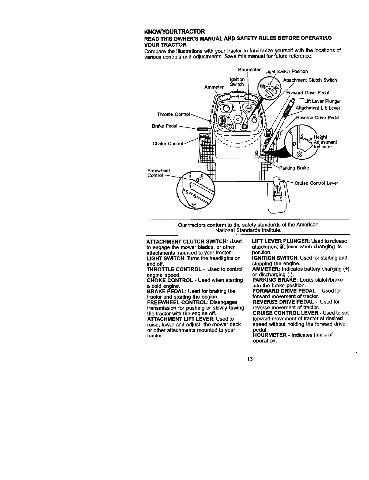
KNOWYOURTRACTOR
READTHISOWNER'SMANUALANDSAFETYRULESBEFOREOPERATING
YOURTRACTOR
Compare the illustrationswith your tractor to familiarize yourself with the locationsof
vadous controlsand adjustments. Save this manual for future reference.
Amme_r
Hourmeter LightSwitch Position
Igni'don Attachment Clutch Switch
Switch
Drive Pedal
Attachment Uft Lever
Drive Pedal
Choke Adjustment
nd cator
Freewheel
I Brake
Control Lever
Our tractorsconform tothe safety standards ofthe Amedcan
National Standards Institute.
ATTACHMENT CLUTCH SWITCH: Used
to engage the mower blades, or other
attachments mounted toyour tractor.
LIGHT SWITCH: Turns the headlights on
and off.
THROTTLE CONTROL- Used to control
engine speed.
CHOKE CONTROL - Used when starting
a cold engine.
BRAKE PEDAL: Used for braking the
tractor and starting the engine.
FREEWHEEL CONTROL: Disengages
transmissionfor pushing or slowlytowing
the tractorwith the engine off.
ATTACHMENT LIFT LEVER: Used to
raise, lower and adjust the mower deck
or other attachments mounted to your
tractor.
LIFT LEVER PLUNGER: Used torelease
attachment lift lever when changingits
position.
IGNITION SWITCH: Used forstartingand
stopping the engine.
AMMETER: Indicates battery charging (+)
or discharging (-).
PARKING BRAKE: Locks clutch/brake
into the brake position.
FORWARD DRIVE PEDAL- Used for
forward movement of tractor.
REVERSE DRIVE PEDAL- Used for
reverse movement of tractor.
CRUISE CONTROL LEVER - Used toset
forward movement of tractor at desired
speed without holding the forward ddve
pedal.
HOURMETER - Indicates hours of
operation.
13
Theoperationofanytractorcanresultinforeign objects thrown into the I
eyes, which can result in severe eye damage. Always wear safety glasses I
or eye shields while operating your tractor or performingany adjustments I
or repairs. We recommend a wide vision safety mask over spectacles, or
standard safety glasses.
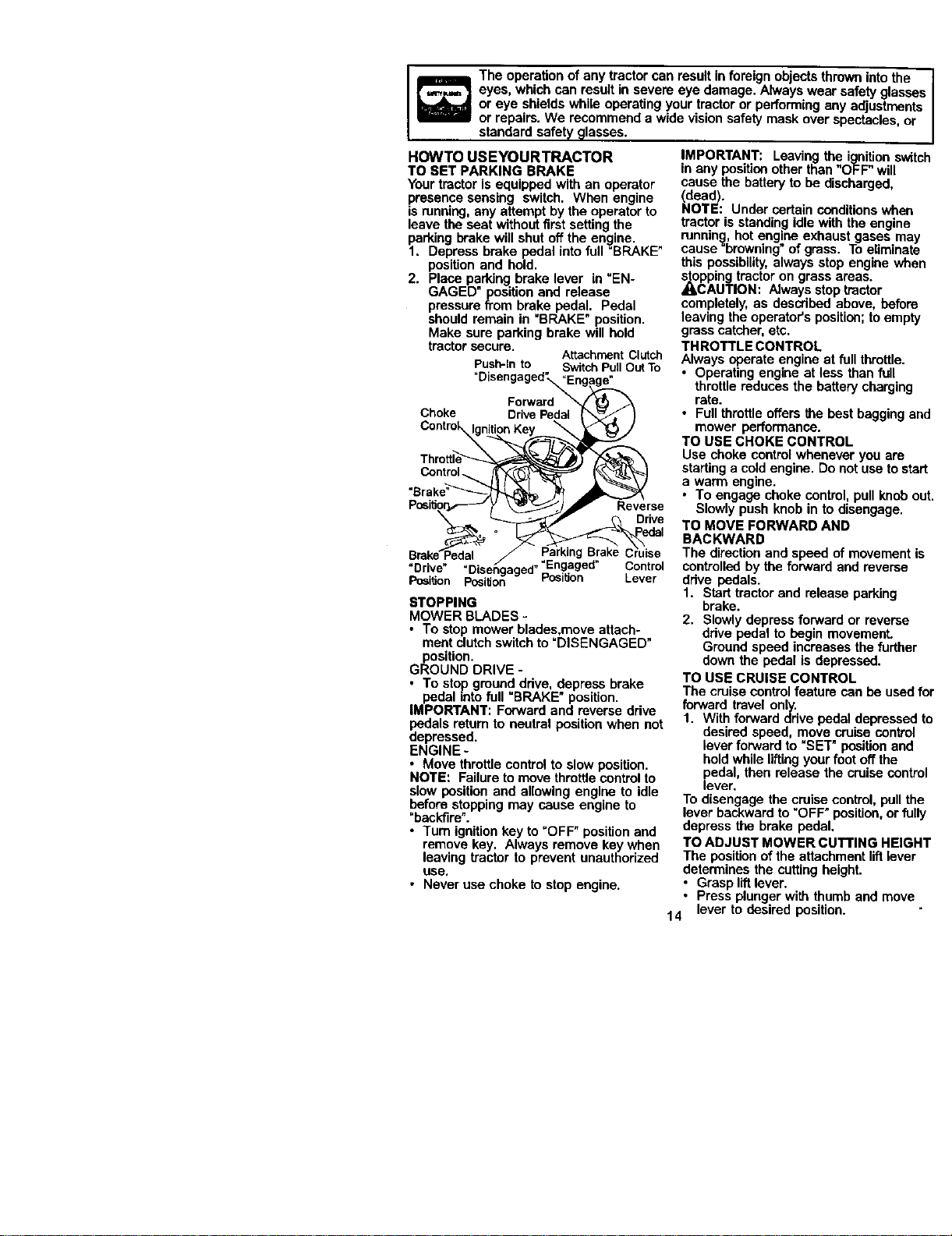
HOWTO USEYOURTRACTOR
TO SET PARKING BRAKE
Your tractor is equipped with an operator
presence sensing switch. When engine
ISrunning, any attempt by the operator to
leave the seat without first setting the
parking brake will shut off the engine.
1. Depress brake pedal into full"BRAKE"
position and hold.
2. Place parking brake lever in "EN-
GAGED" positionand release
pressure from brake pedal. Pedal
should remain in =BRAKE"position.
Make sure parking brake will held
tractor secure.
AttachmentClutch
Push-Into SwitchPullOutTo
"Disengaged"_ngag_
Forward _ _
Choke Drive Pedal
Throttle
Control
PositJo_ y \_ _J'/,_P" Reverse
Drive
Drive Disengaged _#.
Posi_on Position Position Lever
STOPPING
MOWER BLADES -
• To stop mower blades,move attach-
ment clutchswitch to "DISENGAGED"
position.
GROUND DRIVE -
• To stop ground drive, depress brake
pedal intofull "BRAKE" position.
IMPORTANT'. Forward and reverse drive
pedals return to neutral position when not
depressed.
ENGINE-
• Move throttle control to slow position.
NOTE: Failure to move throttle control to
slow position and allowing engine to idle
before stopping may cause engine to
"backfire".
• Turn ignition key to "OFF" position and
remove key. Always remove key when
leaving tractor to prevent unautherized
use.
• Never use choke to stop engine.
IMPORTANT: Leaving the ignitionswitch
in any position other than "OFF" will
cause the battery to be discharged,
Ndead).
OTE: Under certain conditionswhen
tractor is standing idle with the engine
running, hot engine exhaust gases may
cause"browning" of grass. Toeliminate
this possibility, always stop engine when
_kOcppingtractoron grass areas.
AUTION: Alwaysstop tractor
completely, as described above, before
leaving the operator's position;to empty
grass catcher,etc.
THROTTLE CONTROL
Always operate engine at full throttle.
• Operating engine at less than full
throttlereduces the battery charging
rate.
• Full throttle offers the best bagging and
mower performance.
TO USE CHOKE CONTROL
Use choke control whenever you are
starting a cold engine. Do not use to start
e warm engine.
• To engage choke control, pull knob out,
Slowly push knob in to disengage.
TO MOVE FORWARD AND
BACKWARD
The directionand speed of movement is
controlled by the forward and reverse
drive pedals.
1. Start tractor and release parking
brake.
2. Slowly depress forward or reverse
drive pedal to begin movement.
Ground speed increases the further
down the pedal is depressed.
TO USE CRUISE CONTROL
The cruise control feature can be usedfor
forward travel only.
1. With forward drive pedal depressed to
desired speed, move cruise control
leverforward to "SET" positionand
holdwhile liftingyour foot off the
pedal, then release the cruise control
lever.
To disengage the cruise control, pull the
lever backward to "OFF" position,or fully
depress the brake pedal.
TO ADJUST MOWER CUTTING HEIGHT
The positionof the attachment liftlever
determines the cutting heighL
• Grasp liftlever.
• Press plunger with thumband move
14 lever to desired position.
Thecuttingheightrangeisapproxi-
mately1-1/2to4".Theheightsare
measuredfromthegroundtotheblade
tipwiththeenginenotrunning.These
heightsareapproximate end may vary
depending upon soil conditions,height of
grass andtypes of grass being mowed.
The average lawn shouldbe cut to
approximately 2-1/2 inches during the
cool season and to over 3 inches
during hot months. For healthier and
better lookinglawns, mow often and
after moderate growth.
• For best cuttingperformance, grass
over 6 inches in height should be
mowed twice. Make the first cut
relativelyhigh; the second to desired
height.
TO ADJUST GAUGE WHEELS
Gauge wheels ere property adjusted
when they are slightlyoff the ground
when mower is at the desired cutting
height in operating position. Gauge
wheels then keep the deck in proper
position to help prevent scalping in most
terrain conditions.
NOTE: Be sure tractor ison a fiat level
surface.
1. Lower mower and adjust mower to
desired cutting height.
2. Remove retainer spring end clevis pin
which secure each gauge wheel bar.
3. Lower gauge wheels to ground. Raise
bgaugewheels slightlyto align holes in
racket and gauge wheel bar and
insert clevis pin. Gauge wheels
should be slightly off the ground.
4. Replace retainer spdng into clevis pin.
5. Be sure all gauge wheels are in the
same setting.
IMPORTANT: Be sure toreadjust gauge
wheels if you change the cutting height
of the mower deck.
.F
Retainer
Spfin
TO OPERATE MOWER
Your tractor is equipped with an operator
presence sensing switch. Any attempt by
the operator to leave the seat with the
engine runningand the attachment clutch
engaged will shut off the engine.
1. Select desired height of cut.
2. Start mower blades by engaging
attachment clutch control.
15
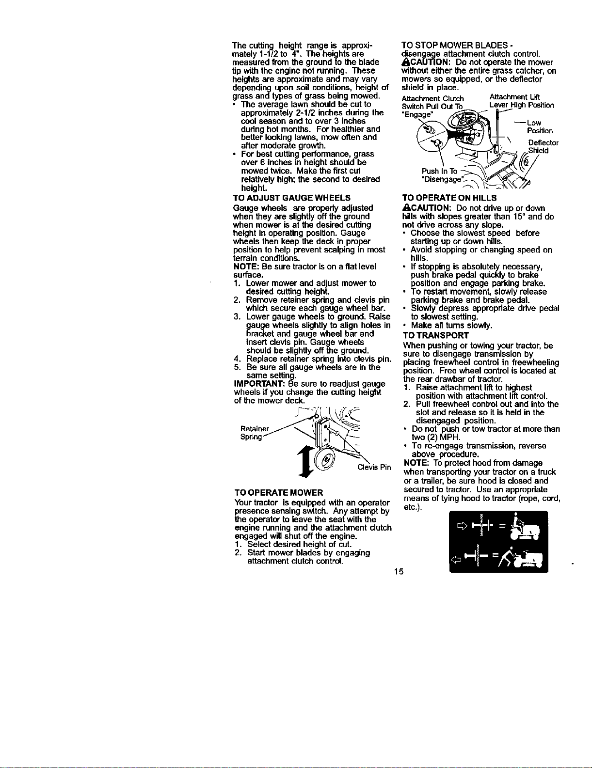
TO STOP MOWER BLADES o
disen_lecleattachment clutch control.
_,CA[J'IIOH: De not operate the mower
without either the entire grass catcher, on
mowers so equipped, or the deflector
shield in place.
AttachmentClutch AttachmentLift
SwitchPullOutTo LeverHighPosition
"Engage" ..--I
_ _ PosiSon
tor
=Disengage"_._
TO OPERATE ON HILLS
ACAUTION: Do net drive upor down
hillswith slopes greater than 15° and do
notdrive across any slope.
• Choose the slowest speed before
starting up or down hills.
• Avoid stopping or changing speed on
hills.
• If stopping is absolutely necessary,
push brake pedal quickly to brake
position and engage perking brake.
• To restart movement, slowly release
parking brake and brake pedal.
• Slowly depress appropdeta drive pedal
toslowest setting.
• Make all tams slowly.
TO TRANSPORT
When pushing or towing your tractor,be
sure to disengage transmissionby
placing freewheel control in freewheeling
position. Free wheel control is located at
the rear drawbar of tractor.
1. Raise attachment liftto highest
positionwith attachment liftcontrol.
2. Pull freewheel control out and into the
slot and release so it is held in the
disengaged position.
• Do not push or tow tractor at more than
two (2) MPH.
• To re-engage transmission, reverse
above procedure.
NOTE: To protect hood from damage
when transporting your tractor on a truck
or a trailer, be sure hood isclosed and
secured to tractor. Use an appropriate
means of tyinghood to tractor (rope, cord,
etc.).
TOWINGCARTSANDOTHERATTACH-
MENTS
Towonlytheattachmentsthatare
recommendedbyandcomplywith
specificationsofthe manufacturer of your
tractor.Use common sense when towing.
Too heavy of a load, while on a slope, is
dangerous. Tires can lose tractionwith
the ground and cause you to lose control
ofyour tractor.
BEFORE STARTING THE ENGINE
CHECK ENGINE OIL LEVEL
The engine in your tractor has been
shipped, from the factory, already filled
with summer weight oil.
1. Check engine oil with tractor on level
ground.
2. Unthread and remove oil fill cap/
dipstick;wipe oil off. Reinsert the
dipstick intothe tube and rest oil fill
cap on the tube. Do not thread the
cap onto the tube. Remove and read
oil level. If necessary, add oil until
"FULL" mark on dipstick is reached.
Do not ove_ll.
• For coldweather operationyou should
change oilforcosier starting (Sen "OIL
VISCOSITY CHART" inthe Mainte-
nance section ofthis manual).
• To change engine oil, see the Mainte-
nance section in this manual.
ADD GASOLINE
• Fill fuel tank. Use fresh, clean, regular
unleaded gasoline with a minimum of
87 octane. (Use of leaded gasoline will
increase carbon and lead oxide
deposits and reduce valve life). Do not
mix oil with gasoline. Purchase fuel in
quantities that can be used within 30
days to assure fuel freshness.
IMPORTANT: When operating in tem-
peratures below 32°F(0°C), use fresh,
clean winter grade gasoline to help
insure good cold weather starting.
AWARNING: Experience indicates that
alcohol blended fuels (called gasohol or
using ethanol or methanol) can attract
moisture which leads to separation and
formation of acids dudng storage. Acidic
gas can damage the fuel system of an
engine while in storage. Toavoid engine
problems, the fuel system should be
emptied before storage of 30 days or
longer. Drain the gas tank, start the
engine and let it run until the fuel lines
and carburetor are empty. Use fresh fuel
next season. See Storage Instructionsfor
additional information. Never use engine
or carburetor cleaner products in the fuel
tank or permanent damage may occur.
_kCAUTION: Fillto bottomof gas tank
filler neck. De not overfill.Wipe off any
spilled oil or fuel. Do not store, spillor use
gasoline near an open flame.
TO START ENGINE
When startingthe engine for the first time
or if the engine has run out offuel, it will
take extra cranking time to move fuel from
the tank to the engine.
1. Be sure freewheel control is in the
transmission engaged position.
2. Sit on seat in operatingposition,
depress brake pedal and set perking
brake.
3. Move attachment clutchto =DISEN-
GAGED" position.
4. Move throttlecontrol tofast position
5. Pull choke control out fer a cold
engine start attempt. For a warm
engine start attempt the choke control
may not he needed.
NOTE: Before starting,read the warm and
cold starting procedures below.
6. insert key into ignitionand turn key
clockwiseto "START" positionand
release key as coon as engine starts.
Do notrun starter continuously for
more than fifteen seconds per minute.
If the engine does not start after
several attempts, push choke control
in, wait a few minutesand try again. If
engine still does not start, pullthe
choke controlout and retry.
WARM WEATHER STARTING (50° F and
above)
7. When engine starts, slowly push
choke control in untilthe engine
begins to run smoothly. If the engine
starts to run roughly,pull the choke
control out slightlyfor a few seconds
and then continue to push the control
in slowly.
• The attachments and ground ddve can
now be used. If the engine does not
accept the load, restartthe engine and
allow itto warm up for one minute
using the choke as descdbed above.
COLD WEATHER STARTING (50° F and
below)
7. When engine starts, slowlypush
choke control in until the engine
begins to run smoothly. Continue to
push the choke controlin small steps
allowing the engine to accept small
changes in speed and load, until the
choke control is fully in. Ifthe engine
startsto run roughly,pull the choke
controlout slightlyfor a few seconds
and then continue to push the control
in slowly. This may require an engine
warm-up period from several seconds
to several minutes, depending on the
16 temperature.
AUTOMATIC TRANSMISSION WARM UP
Before driving the unit in cold weather,
the transmission should be warmed up as
follows:
1. Be sure the tractor is on level ground.
2. Release the parking brake and let the
brake slowly return to operating
position.
3. Allow one minute for transmissionto
warm up. This can be done during the
engine warm up pedod.
• The attachments can be used dudng
the engine warm-up peded after the
transmissionhas been warmed up and
may require the choke control be
pulled out slightly.
NOTE: If at a high altitude(above 3000
feet) or in cold temperatures (below 32 F)
the carburetor fuel mixture may need to
be adjusted for best engine performance.
See "TO ADJUST CARBURETOR" in the
Service and Adjustmentssection of this
manual.
PURGETRANSMISSION
_,CAUTION: Never engage or disengage
freewheel lever while the engine is
running.
Toensure proper operation and perfor-
maace, itis recommended thatthe
transmissionbe purged before operating
tractorfor thefirsttime. This pmcadure will
remove any trapped air inside the trans-
missionwhich may have developed during
shippingofyour tractor.
IMPORTANT: Should your transmission
require removalfor serviceor replacement,
it should be purged after relastallation
before operatingthe tractor.
1. Place tractor safely on level surface
with engine off and parking brake set.
2. Disengage transmissionby placing
freewheel control in freewheeling
position (See "TO TRANSPORT" in
this section of manual).
3. Sittingin the tractor seat, start engine.
After the engine is running, move
throttle controlto slow position.
Disengage parking brake.
4. Depress forward drive pedal to full
forward position and hold for five (5)
seconds and release pedal. Depress
reverse ddve pedal to full reverse
position and hold for five (5) seconds
and release pedal. Repeat this
procedure three (3) times.
NOTE: Dudng this procedurethere will be
no movementof ddvewheels. The air is
being removed from hydraulicdrive
system.
5. Shut- off engine and set parking
brake.
17
6. Engage transmission by placing
freewheel control in ddving position
(See "TO TRANSPORT" in this section
of manual).
7. Siftingin the tractor seat, start engine.
After the engine is running, move
throttlecontrol to half (1/2) speed.
Disengage parking brake.
8. Ddve tractor forward for approximately
five feet then backwards forfive feet.
Repeat this driving procedure three
times.
Your tractor is now purged and now ready
for normal operation.
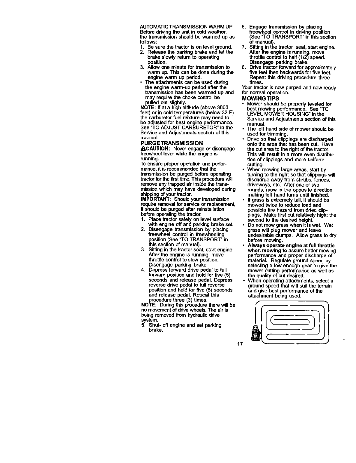
MOWlNGTIPS
• Mower should be properly leveled for
best mowing performance. See "TO
LEVEL MOWER HOUSING" in the
Service and Adjustments section of this
manual.
• The left hand side of mower should be
usedfor trimming.
• Ddve so that clippings are discharged
onto the area that has been cut. Have
the cut area to the right of the tractor.
This will result in a mere even distdbu-
tion of clippings and more uniform
cutting.
• When mowing large areas, start by
turningto the dght so that clippingswill
discharge away from shrubs, fences,
ddveways, etc. After one ortwo
rounds, mow in the opposite direction
making left hand turns untilfinished.
• If grass is extremely tall, it should be
mowed twice to reduce load and
possible fire hazard from dded clip-
pings. Make first cut relativelyhigh;the
second to the desired height.
• Do not mow grass when it iswet. Wet
grass will plug mower and leave
undesirable clumps. Allow grass to dry
before mowing.
• Always operate engine at full throttle
when mowing to assure better mowing
performance and proper discharge of
matedal. Regulate ground speed by
selecting a lowenough gear to give the
mower cuttingperformance as well as
the quality of cut desired.
• When operatingattachments, select a
ground speed that will suit the terrain
and give best performance of the
attachment being used.
CheCkBrakeOperation _ ip#
CheCk Tire Plessufe I_
Check Operator Prelsence and
T 1In_cxsy_lems Vt
Ri cr_ckf= L0o_Fasleners I/ I/7 f,/
ShBrpe_'Replace Mowe_ B_ des I_/_
T J..D,'_ionCha_ S/ IV/
0 Check Batteo/Level
R clean Bafleq/and Tewninals ll/ li/
CheCk Transaxle Cooling
Adjust B_de Eelt(sJ Tension _
Adjust Motion Drive Belt(s) Tension ft/_
Chl_CkEngine Oil Level I_
Change Er_gineOil II_ I# #
E clean Air Filter V/I
N Clean Air Screen _1_l
Inspect Muffler/Sp_k A=re_tet
Replace Oil FiRe¢(if equipped) _ 2
I_ Clean Engine Cooling Fins _z
Replace Spa_k Plug iS' I_
Replace Air Filter Paper Cadrldge _/2
Replace Fuel Filter
GENERAL RECOMMENDATIONS
The warranty on thistractordoes not cover
items thathave been subjected to operator
abuse or negligence. To receive full value
from the warranty,operatormust maintain
tractor as instructedin this manual.
Some adjustmentswill need to be made
periodically to properly maintain your
tractor.
Alladjustments in the Service and
Adjustmentssectionof this manual should
be checked at least once each season.
• Once a year you should replace the
spark plug,clean or replace air filter,and
check blades and beltsforwear. A new
spark plugand clean air filter assure
proper air-fueimixture and help your
engine run better and lastlonger.
BEFORE EACH USE
1, Check engine oil level.
2, Check brake operation.
3. Check tire pressure.
4. Check operator presence and
intedock systems for proper operation.
5. Check for loose fasteners.
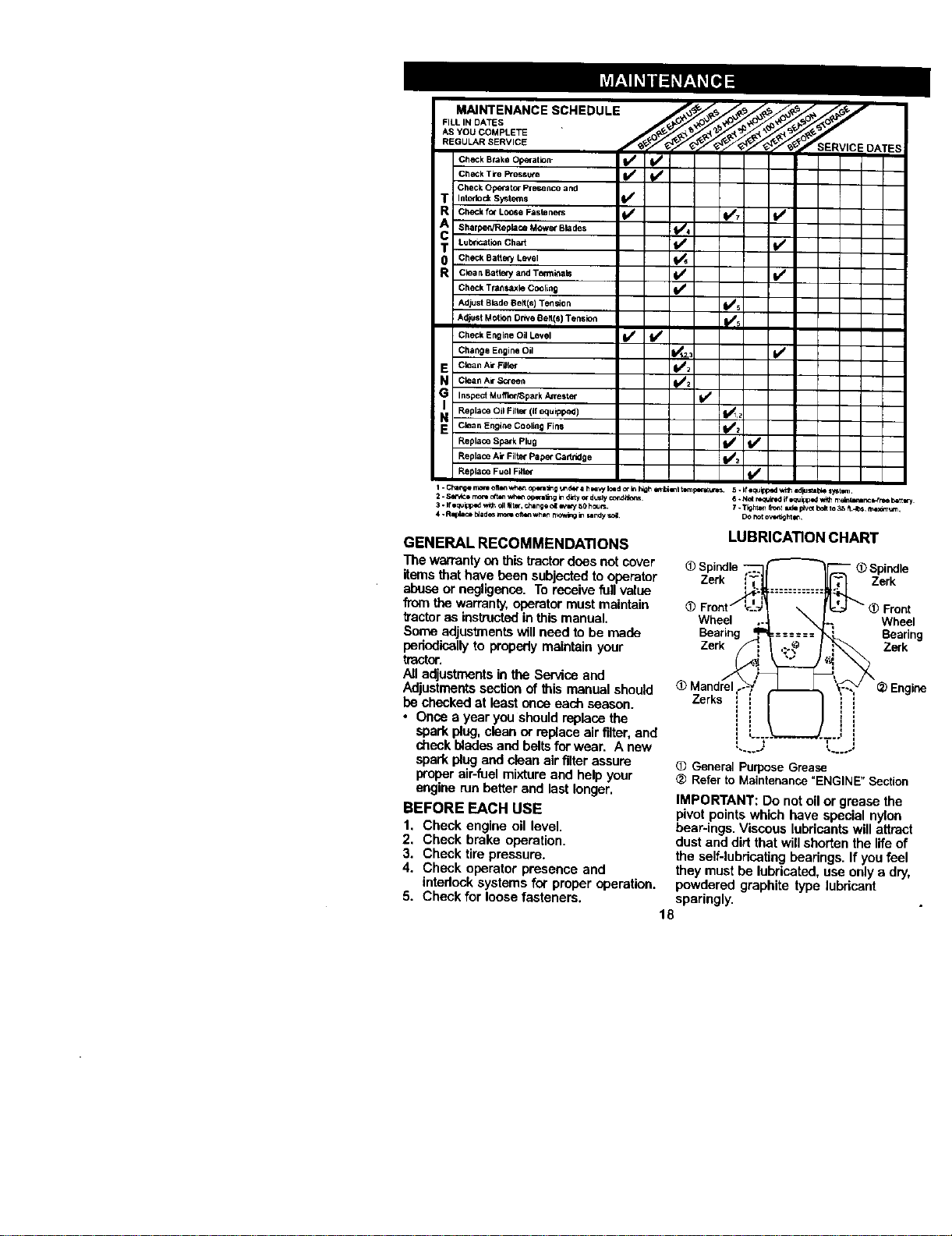
LUBRICATION CHART
_) Spindle
Zerk Zerk
Wheel Wheel
Bearing Bearing
Zer_ Zerk
General Purpose Grease
<_ Refer to Maintenance "ENGINE" Section
IMPORTANT: Do not oil or grease the
pivot points which have special nylon
bear-ings. Viscous lubricants willattract
dust and dirt that will shorten the life of
the seif-lubricatingbearings. If you feel
theymust be lubricated, use onlya dry,
powdered graphite type lubricant
sparingly.
18
TRACTOR
Alwaysobservesafetyruleswhen
performinganymaintenance.
BRAKEOPERATION
Iftractorrequiresmorethansix(6)feet
stoppingdistanceathighspeedin
highestgear,thenbrakemustbead-
justed.(See"TOADJUSTBRAKE"inthe
ServiceandAdjustmentssectionofthis
manual).
TIRES
• Maintainproperairpressureinalltires
(See=PRODUCT SPECIFICATIONS"
section of this manual).
• Keep tiresfree of gasoline, oil,or insect
control chemicals which can harm
rubber.
• Avoid stumps, stones, deep ruts, sharp
objects and other hazards that may
cause tire damage.
NOTE: To seal tire punctures and prevent
fiat tiresdue toslow leaks, tire sealant
may be purchased from your local parts
dealer. Tire sealant also prevents tire dry
rot and corrosion.
OPERATOR PRESENCE SYSTEM
Be sure that operator presence and
interlock systems are workingproperly, if
your tractor does not function as de-
scdbed below, repair the problem
immediately.
• The engine should not start unless the
brake pedal is fully depressed and
attachment clutchcontrol is in the
disengaged position.
• When the engine is running, any
attempt by the operatorto leave the
seat without first setting the parking
brake shouldshut off the engine.
• When the engine is runningand the
attachment dutch is engaged, any
attempt by the operator to leave the
seat should shutoff the engine.
• The attachment clutchshould never
operate unless the operator is in the
seat.
BLADE CARE
For best results mower blades must be
keptsharp. Replace bent or damaged
blades.
BLADE REMOVAL
1. Raise mower to highest position to
allow access to blades.
2. Remove hex bolt, lock washer and fiat
washer securing blade.
3. Install new or resharpened blade with
trailing edge up towards deck as
shown.
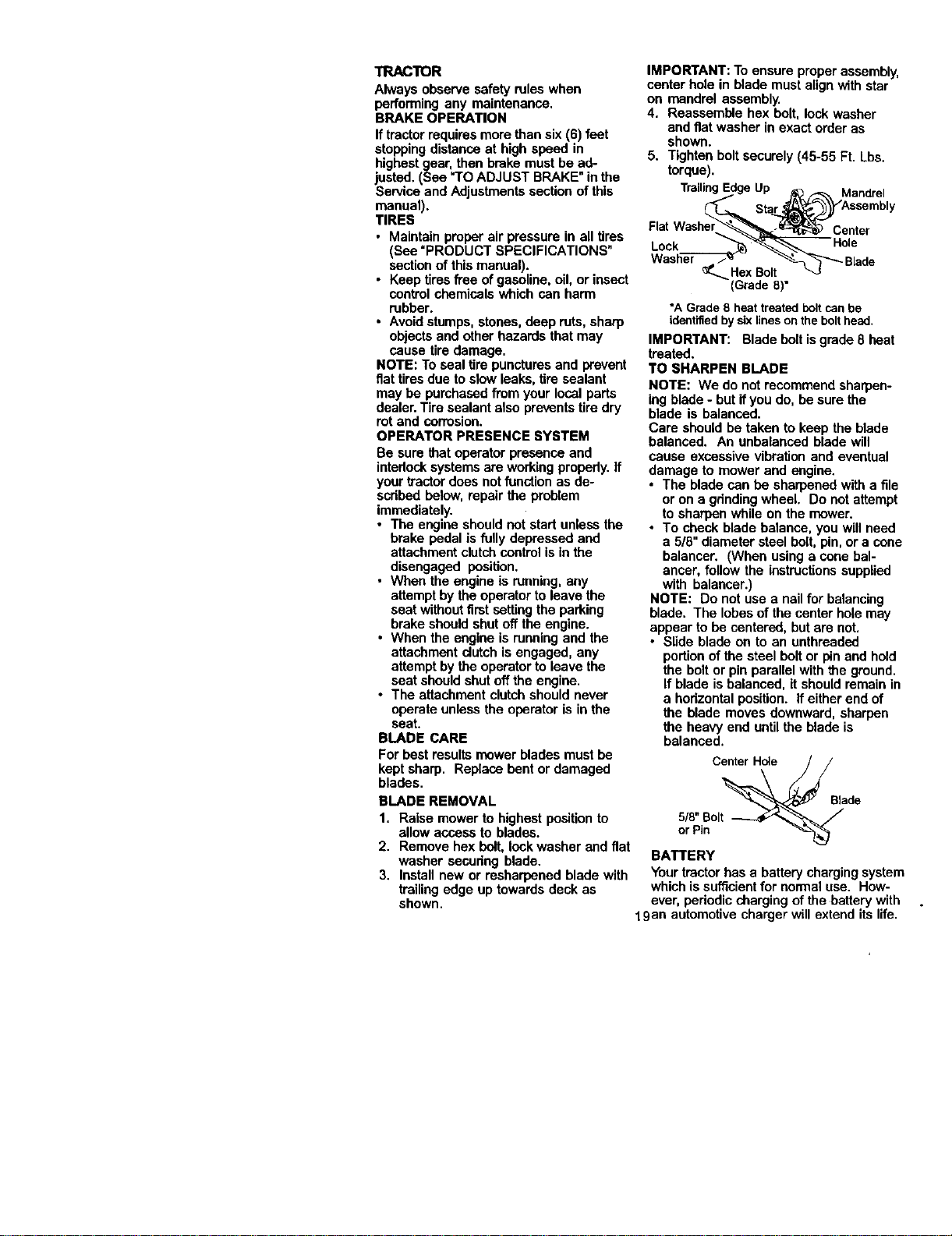
IMPORTANT: To ensure proper assembly,
center hole in blade must align with star
on mandrel assembly.
4. Reassemble hex bolt, lock washer
and fiat washer in exact order as
shown.
5. Tighten boltsecurely (45-55 Ft. Lbs.
torque).
Trailing Up Mandrel
Flat
Lock
Center
(Grade 8)°
"A Grade8 heattreatedboltcanbe
identifiedbysixlinesontheboltheed.
IMPORTANT: Blade bolt isgrade 8 heat
treated.
TO SHARPEN BLADE
NOTE: We do not recommend sharpen-
ing blade - but ifyou do, be sure the
blade is balanced.
Care should be taken to keep the blade
balanced. An unbalanced blade will
cause excessive vibration and eventual
damage to mower and engine.
• The blade can be sharpened with a file
or on a grinding wheel. Do not attempt
to sharpen while on the mower.
• To check blade balance, you will need
a 5/8" diameter steel bolt, pin, or a cone
balancer. (When using a cone bal-
ancar, follow the instructions supplied
with balancar.)
NOTE: Do not use a nail for balancing
blade. The lobes of the center hole may
appear to be centered, but are not.
• Slide blade on to an unthreaded
portionof the steel boltor pin and hold
the bolt or pin parallel with the ground.
If blade is balanced, it should remain in
a hodzontal position. If either end of
the blade moves downward, sharpen
the heavy end until the blade is
balanced.
Center Hole
_Blede
518"Bolt /
or Pin -_,_
BATTERY
Your tractor has a battery chargingsystem
which is sufficientfor normal use. How-
ever, periodic charging of the battery with
19an automotive charger will extend its life.
• Keep battery and terminals clean.
• Keep battery bolts tight,
• Keep small vent holes open.
• Recharge at 6-10 amperes for 1 hour.
NOTE: The odginal equipment battery on
your tractor is maintenance free. Do not
attempt to open or remove caps or covers,
Adding or checking level of electrolyte is
not necessary.
TO CLEAN BATTERY AND TERMINALS
Corrosion and dirt on the battery and
terminals can cause the battery to "leak"
power.
1. Remove terminal guard.
2. Disconnect BLACK battery cable first
then RED battery cable and remove
batteryfrom tractor.
3. Rinse the battery with plain water and
dry.
4. Clean terminals end battery cable
ends with wire brush until bright.
5. Coat terminals with grease or petro-
leum jelly.
6. Reinstall battery (See "REPLACING
BATTERY" in the SERVICE AND
ADJUSTMENTS section of this
manual).
V-BELTS
Check V-belts for deterioration and wear
after 100 hours of operation and replace
if necessary.The beltsare not adjustable.
Replace beltsif they begin to slipfrom
wear.
TRANSAXLE COOLING
The transmissionfan and coolingfins
should be kept clean to assure proper
cooling.
Do notattempt toclean fan or transmis-
sionwhile engine is running or while the
transmissionis hot. To prevent possible
damage to seals, do not use high
pressure water or steam to clean
transaxle.
• Inspect coolingfan to be sure fan
blades are intact and clean.
• Inspect coolingfins for dirt, grass
clippings and other materials. To
prevent damage to seals, do not use
compressed air or high pressure
sprayer to clean cooling fins.
TRANSAXLE PUMP FLUID
The trensaxle was sealed at the factory
and fluid maintenance is not required for
the life ofthe transaxle. Should the
transaxle ever leak or require servicing,
contact your nearest authorized service
center/department.
ENGINE
LUBRICATION
Only use high quality detergent oil rated
with API service classificationSF-SJ,
Select the oil'sSAE viscositygrade
according to your expected operating
temperature,
Change the oil after every 50 hoursof
operationor at least once a year if the
tractor is not usedfor 50 hours in one
year.
Check the crankcase oil level before
starting the engine and after each eight
(8) hoursof operation. Tighten oil fillcap/
dipstick securelyeach time you check the
oil level.
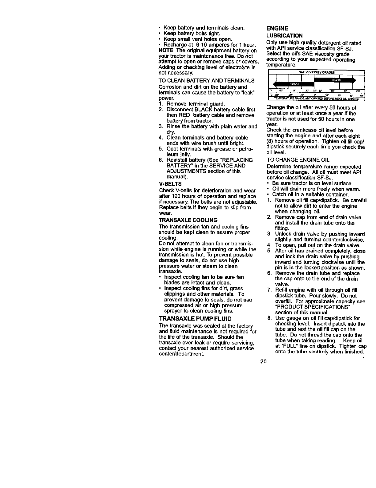
TO CHANGE ENGINE OIL
Determine temperature range expected
before oil change. All oil must meet API
service classificationSF-SJ.
• Be sure tractor is on level surface.
• Oil will drain more freely when warm.
• Catch oil in a suitable container.
1. Remove oil fill cap/dipstick. Be careful
notto allow dirtto enter the engine
when changing oil.
2. Remove cap from end of drainvalve
and installthe drain tube onto the
fitting.
3. Unlock drain valve by pushing inward
slightly and turning counterclockwise.
4. To open, pull out on the drain valve.
5. After oil has drained completely, close
and lock the drain valve by pushing
inward and turning clockwiseuntil the
pin is in the locked positionas shown.
6. Remove the drain tube and replace
the cap onto tothe end of the drain
valve.
7. Refill engine with oil through oil fill
dipstick tube. Pour slowly. Do not
overfill. For approximate capacity see
"PRODUCT SPECIFICATIONS"
section of this manual.
8. Use gauge on oil fill cap/dipstick for
checkinglevel. Insert dipstickintothe
tube and rest the oil fill cap on the
tube. Do not thread the cap onto the
tube when taking reading. Keep oil
at =FULL" line on dipstick. Tighten cap
onto the tube securely when finished.
2O
Closed
and
Locked
Position
Cap
Oil DrainValve
Drain Tube
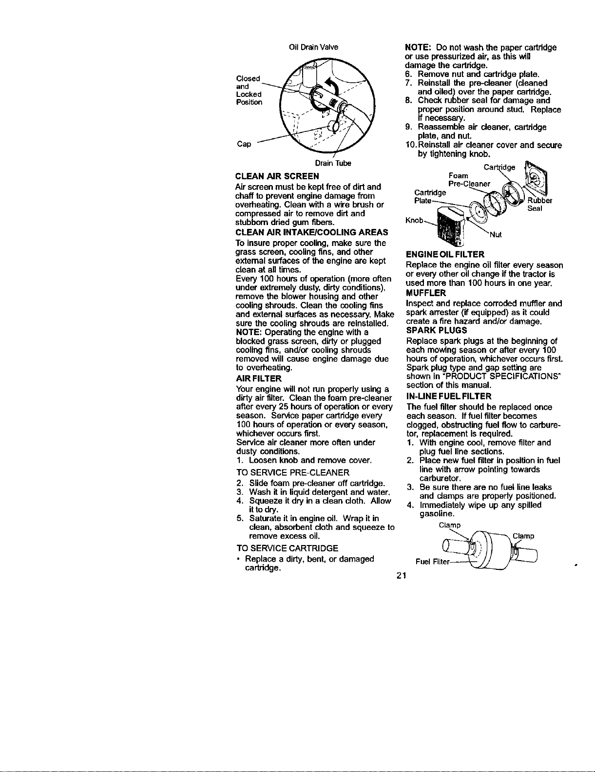
NOTE: Do not wash the paper cartridge
or use pressurized air, as this will
damage the cartridge.
6. Remove nutand cartridge plate.
7. Reinstall the pre-cleaner (cleaned
and oiled) over the paper cartridge.
8. Check rubber seal for damage and
proper positionaround stud. Replace
if necessa_.
9. Reassemble air cleaner, cartridge
plate, and nut.
10. Reinstall air cleaner cover and secure
by tightening knob.
CLEAN AIR SCREEN
Air screen must be kept free of dirtand
chaff to prevent engine damage from
overheating. Clean with a wire brush or
compressed air to remove dirt and
stubbem dried gum fibers.
CLEAN AIR INTAKE/COOLING AREAS
To insure proper cooling, make sure the
grass screen, cooling fins, and other
external surfaces of the engine are kept
clean at all times.
Every 100 hours of operation (more often
under extremely dusty,dirty conditions),
remove the blower housing and other
cooling shrouds. Clean the coolingfins
and external surfaces as necessary. Make
sure the cooling shrouds are reinstalled.
NOTE: Operating the engine with a
blocked grass screen, dirtyor plugged
coolingfins, and/er cooling shrouds
removed will cause engine damage due
to overheating.
AIR FILTER
Your engine will not run properly using a
dirty air filter. Clean the foam pre-cleaner
after every 25 hours of operation or every
season. Service paper cartridge every
100 hours of operation or every season,
whichever occurs first.
Service air cleaner more often under
dusty conditions.
1. Loosen knob and remove cover.
TO SERVICE PRE-CLEANER
2. Slide foam pre-cleaner off cartridge.
3. Wash it in liquid detergent and water.
4. Squeeze it dry in a clean cloth. Allow
it to dry.
5. Saturate it in engine oil. Wrap it in
clean, absorbent cloth and squeeze to
remove excess oil.
TO SERVICE CARTRIDGE
• Replace a dirty, bent, or damaged
cartridge.
ENGINE OIL FILTER
Replace the engine oil filter every season
or every other oilchange if the tractoris
used more than 100 hours in one year.
MUFFLER
Inspect and replace corroded muffler and
spark arrester (if equipped) as it could
create a fire hazard and/or damage,
SPARK PLUGS
Replace spark plugs at the beginning of
each mowing season or after every 100
hours of operation, whichever occurs first.
Spark plug type and gap setting are
shown in "PRODUCT SPECIFICATIONS"
section of this manual.
IN-LINE FUEL FILTER
The fuel filter should be replaced once
each season. Iffuel filter becomes
clogged, obstructingfuel flow to carbure-
tor, replacement is required.
1. With engine cool, remove filterand
plug fuel line sections.
2. Place new fuel filter in positionin fuel
line with arrow pointingtowards
carburetor,
3, Be sure there are no fuel line leaks
and clamps are properly posiUoned.
4, Immediately wipe up any spilled
gasoline.
Clamp
FuelFilter_
Foam
Pre-Cleaner
Cartridge
Rubber
Seal
21
CLEANING
• Cleanengine,battery,seat,finish,etc.
ofall foreign matter.
• Keep finished surfaces and wheels free
of all gasoline, oil, etc.
• Protect painted surfaces with automo-
tive type wax.
We do notrecommend usinga garden
hose to clean your tractor unless the
electrical system, muffler, air filter and
carburetor are covered to keep water out.
Water in engine can result in a shortened
engine life.
,_CAUTION: BEFORE PERFORMING ANY SERVICE OR ADJUSTMENTS:
1. Depress brake pedal fully and set parking brake.
2. Place attachment clutch in "DISENGAGED" position.
3. Turn ignitionkey "OFF" and remove key.
4. Make sure the blades and all moving parts have completely stopped.
5. Disconnect spark plug wire from spark plug and place wire where it cannot
come in contact with plug.
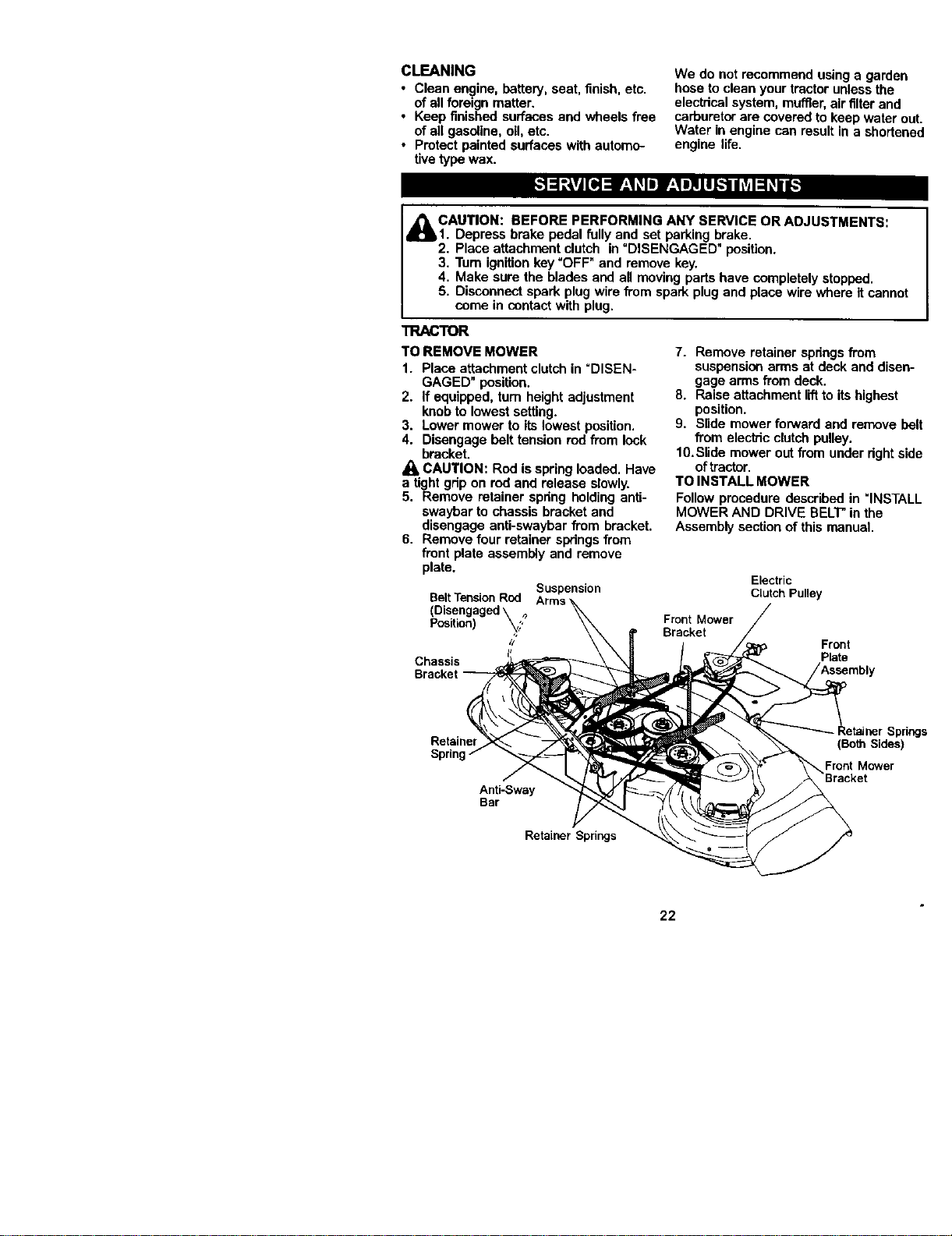
TRACTOR
TO REMOVE MOWER
1. Place attachment clutch in "DISEN-
GAGED" position.
2. If equipped, turn height adjustment
knob to lowest setting.
3. Lower mower to its lowest position.
4. Disengage belt tension rod from lock
bracket,
Jl_ CAUTION: Red is spring loaded. Have
a tight grip on red and release slowly.
5. Remove retainer spring holding anti-
swaybar to chassis bracket and
disengage anti-swaybar from bracket.
6. Remove four retainer springs from
front plate aseemb_yand remove
plate.
Suspension
Belt Tension Rod
(Disengaged\ ,_
Position) _;,
//
Chassis
7. Remove retainer springsfrom
suspensionarms at deck and disen-
gage arms from deck.
8. Raise attachment liftto its highest
position.
9. Slide mower forward and remove belt
from electric clutch pulley.
10.Slide mower out from under dght side
oftractor.
TO INSTALL MOWER
Follow procedure described in "INSTALL
MOWER AND DRIVE BELT' in the
Assembly section of this manual.
Electric
Clutch Pulley
Front Mower
Bracket
Front
Plate
Bracket
Retainer
Sprin
Anti-Sway
Bar
Retainer Springs
iner Springs
(Both Sides)
.Front Mower
Bracket
22
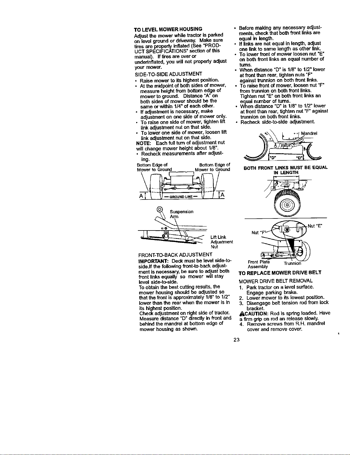
TOLEVELMOWERHOUSING
Adjustthemowerwhiletractorisparked
onlevelgroundordriveway.Makesure
tirosarepropedyinflated(See"PROD-
UCTSPECIFICATIONS"sectionofthis
manual).Iftirosareoveror
undednflated,youwillnotpropedyadjust
your mower.
SIDE-TO-SIDE ADJUSTMENT
• Raise mower to its highest position.
• At the midpointof beth sides of mower,
measure heightfrom bottom edge of
mower toground. Distance "A" on
both sides of mower should be the
same or within 1/4" of each other.
• If adjustment is necessary, make
adjustmenton one side of mower only.
• To raise one side of mower, tightenlift
link adjustment nut on that side.
• To lower one side of mower, loosen lift
link adjustment nut on that side.
NOTE: Each full turnof adjustment nut
will change mower height about 1/8".
• Recheck measurements after adjust-
ing.
BottomEdgeof BottomEdgeof
Mowerto Ground Mowerto Ground
\ /
A_Suspensi°n
Lift Link
Adjustment
Nut
FRONT-TO-BACK ADJUSTMENT
IMPORTANT: Deck must be level side-to-
side.If the following front-to-backadjust-
ment is necessary, be sure to adjust beth
front linksequally so mower will stay
level side-to-side.
To obtain the bestcuttingresults, the
mower housing should be adjusted so
that the front is approximately 1/8" to 1/2"
lower than the rear when the mower is in
its highest position.
Check adjustmenton rightside of tractor.
Measure distance "D" directly in front and
behind the mandrel at bottom edge of
mower housing as shown.
• Before making any necessary adjust-
ments, check that beth front linksare
equal In length.
• If links are not equal in length, adjust
one link to same length as other link.
• To lower front of mower loosennut "E"
on beth front linksan equal number of
turns.
• When distance "D" is 1/8" to 1/2" lower
at front than rear, tighten nuts=F"
against trunnion on both front links.
• To raise front of mower, loosennut =F"
from trunnion on both front links.
Tighten nut =E"on beth frontlinks an
equal number of turns.
• When distance "D" is 1/8" to 112"lower
at front than rear, tightennut "F"against
trunnionon bothfront links.
• Recheck side-to-side adjustment.
BOTH FRONTLINKS MUST BE EQUAL
IN LENGTH
Front Plate Trunnion
Assembly
TO REPLACE MOWER DRIVE BELT
MOWER DRIVE BELT REMOVAL
1. Park tractor on a level surface.
Engage parking brake.
2. Lower mower to its lowest position.
3. Disengage belt tension rod from lock
bracket.
_CAUTION: Rod is spring loaded. Have
a firm grip on rodan release slowly.
4. Remove screws from R.H. mandrel
cover and remove cover.
23
5.Removeanydirtorgrassclippings
whichmayhaveaccumulatedaround
mandrelsandentireupperdeck
surface.
6.DisconnectR.H.suspensionarmfrom
rear deck bracket by removing
retainer spring.
7. Carefully roll belt over the top of R.H.
mandrel pulley.
8. Remove belt from electric clutch
pulley.
9. Remove belt from idler pulleys.
10.Check primary idler arm and two
idlers to see that they rotate freely.
11. Be sure spring is securely hooked to
pdmary idleranti and spdng arm.
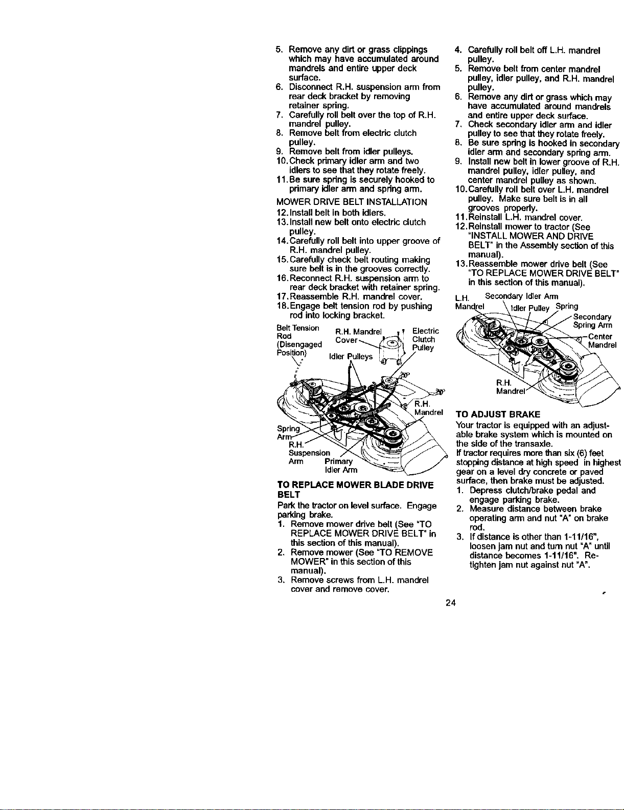
MOWER DRIVE BELT INSTALLATION
12.Install belt in both idlers.
13.Install new belt onto electric clutch
pulley.
14.Carefully rollbelt into upper groove of
R.H. mandrel pulley.
15.Carefully check belt routing making
sure belt is in the grooves correctly.
16.Reconnect R.H. suspension arm to
rear deck bracket with retainer spring.
17.Reassemble R.H. mandrel cover.
18.Engage belt tension rod by pushing
rod intolocking bracket.
BeltTension R.H.Mandrel Electric
Rod
(Disengaged Cover_ Clutch
Posi_n) IdlerPulle
R.H.
Mandrel
R,H. _"
Suspension
Arm Pdmary
IdlerArm
TO REPLACE MOWER BLADE DRIVE
BELT
Park the _actor on levelsurface. Engage
parking brake.
1. Remove mower drive belt (See "TO
REPLACE MOWER DRIVE BELT" in
this section of this manual).
2. Remove mower (See _TOREMOVE
MOWER" in this section ofthis
manual).
3. Remove screws from L.H. mandrel
cover and remove cover.
4. Carefully roll belt off L.H. mandrel
pulley.
5. Remove belt from center mandrel
pulley, idler pulley, and R.H. mandrel
pulley.
6. Remove any dirtor grass whichmay
have accumulated around mandrels
and entire upper deck surface.
7. Check secondary idler arm and idler
pulley to see thatthey rotate freely.
8. Be sure spring is hooked in secondary
idler arm and secondary spdng arm.
9. Install new belt in lower groove of R.H.
mandrel pulley, idler pulley, and
center mandrel pulley as shown.
10.Carefully rollbelt over L.H. mandrel
pulley. Make sure beltis in all
grooves propedy.
11.Reinstall L.H. mandrel cover.
12.Reinstall mower to tractor (See
=INSTALL MOWER AND DRIVE
BELT" in the Assemblysection ofthis
manual).
13. Reassemble mower drive belt (See
"TO REPLACE MOWER DRIVE BELT"
in this section of this manual).
L H SecondaryIdlerArm
Mandrel \tdler Pulley Spring
_--_//Secondary
SpringArm
__lCenter
R.H.
TO ADJUST BRAKE
Yourtractor is equipped with an adjust-
able brake system which is mounted on
the side ofthe transaxle.
ff tractorrequires more than six(6) feet
stoppingdistance at high speed in highest
gear on a level dry concrete or paved
surface, then brake must be adjusted.
1. Depress clutch/brake pedal and
engage parking brake.
2. Measure distance between brake
operating arm and nut =A"on brake
red.
3, Ifdistance is other than 1-11/16",
loosen jam nut and turn nut =A_until
distance becomes 1-11/16". Re-
tightenjam nut against nut "A".
24
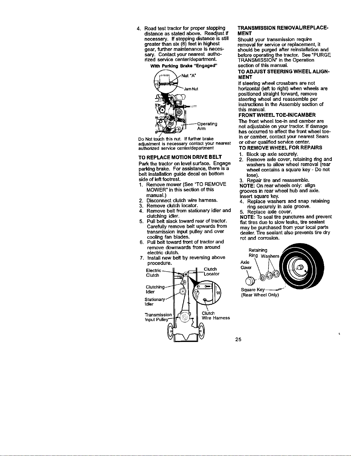
4. Roadtesttractorfor proper stopping
distance as stated above. Readjust if
necessary. If stoppingdistance is still
greater than six (6) feet in highest
gear, further maintenance is neces-
sary. Contact your nearest autho-
rized service center/department.
With Parking Brake "Engaged"
Arm
h this nut. If fudher brake
adjustment is necessary contact your nearest
authodzed service center/department
TO REPLACE MOTION DRIVE BELT
Park the tractoron level surface. Engage
parking brake. For assistance, there is a
belt installation guide decal on bottom
side of leftfootrest.
1. Remove mower (See "TO REMOVE
MOWER" in this section ofthis
manual.)
2. Disconnect clutch wire harness.
3. Remove clutch Iocetor.
4. Remove belt fi'om stationary idler and
clutching idler.
5. Pull belt slack toward rear of tractor.
Carefully remove belt upwards from
transmission input pulley and over
cooling fan blades.
6. Pull belt toward front of tractor and
remove downwards from around
electric clutch.
7. Install new belt by reversing above
procedure.
Electric_ 1
Clutch
Clutching_
Idler
Stationary/
Idler
Transmission "_.......
InputPulley'- _'__(:_
Clutch
--Locator
Clutch
Wire Harness
TRANSMISSION REMOVAUREPLACE-
MENT
Should your transmission require
removal for serviceor replacement, it
should be purged after reinstagation and
before operating the tractor. See "PURGE
TRANSMISSION" in the Operation
sectionof this manual.
TO ADJUST STEERING WHEEL ALIGN-
MENT
If steering wheel crossbars are not
bedzontal (leftto right) when wheels are
positioned straight forward, remove
staedng wheel and reassemble per
instructionsin the Assembly section of
this manual.
FRONT WHEEL TOE-IN/CAMBER
The front wheel toe-in and camber are
notadjustable on your tractor. If damage
has occurred to affect the frontwheel tce-
in or camber, contact your nearest Sears
or other qualified service center.
TO REMOVE WHEEL FOR REPAIRS
1. Block up axle securely.
2. Remove axle cover, retaining dng and
washers to allow wheel removal (rear
wheel contains a square key - Do not
lose).
3. Repair tire and reassemble.
NOTE: On rear wheels only: align
grooves in rear wheel hub and axle.
Insert square key.
4. Replace washers and snap retaining
dng securely in axle groove.
5. Replace axle cover,
NOTE: To seal tire punctures and prevent
fiat tires due to slow leaks, tire sealant
may be purchased from your local parts
dealer. Tire sealant also preventstire dry
rot and corrosion.
(Rear Wheel Only)
25
TO START ENGINE WITH A WEAK
BATTERY
A,CAUTION: Lead-acid batteries
_enerate explosive gases. Keep sparks,
area and smoking matedals away from
batteries. Always wear eye protection
when around battedes.
Ifyour batteryis too weak to start the
engine, It should be recharged. (See
"BATTERY"in the MAINTENANCE
sectionof this manual).
If "jumpercables" are used for emergency
starting,follow this procedure:
IMPORTANT: Your 1factorisequipped
with a 12 volt negative grounded system.
The other vehical must also be a 12 volt
negative grounded system. Do not use
yourtractor battery to start other vehicles.
TO A'(-I'ACHJUMPER CABLES -
1. Connect each end of the RED cable to
the POSITIVE (+) terminal of each
battery, taking care not to short
against chassis.
2. Connect one end of the BLACK cable
to the NEGATIVE (-) terminal of fully
charged battery.
3, Connect the other end of the BLACK
cable to good CHASSIS GROUND,
away from fuel ta_k aed battery.
TO REMOVE CABLES, REVERSE ORDER-
1. BLACK cable first from chassis and
then fromthe ful|y charged battery.
2. RED cable last from both batteries.
"Positiv_'__ _= "Negative"
€+7-
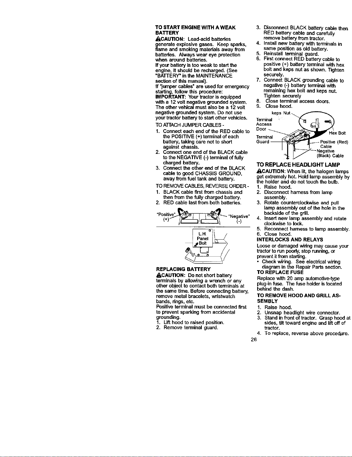
REPLACING BATTERY
_CAUTION: Do not short battery
terminals by allowing a wrench or any
other obiect to contact both ten'_inalsat
the same time. Before connecting battery,
remove metal bracelets, wristwatch
bands, rings,etc,
Positiveterminal must be connected first
to prevent sparking from accidental
grounding.
1. Lift hoed to raised position.
2. Remove terminal guard.
3. Disconnect BLACK battery cable
RED battery cable and carefuUy
remove battery from tractor.
4. Install new battery with terminals
same positionas old battery,
5. Reinstall terminal guard.
6. Firstconnect RED battery cable I
positive (+) battery terminal with
bolt and kegs nut as shown, Tigl"
Securely.
7. Connect BLACK grounding cabh
negative (-) battery terminal with
remaLnthghex bolt and keps nut
Tighten securely
8, Close terminal access doors.
9. Close hood.
keps Nut
Terminal
Acces_Door He;
Terrni
Guard Positive
' I _Negative
_; _ (Black)C_
TO REPLACE HEADLIGHT LAM
_kCAUTION: When lit, the halogen I
get extremely hot. Hold lamp assam
the holder and do not touch the bull:
1. Raise hood.
2. Disconnect harness from lamp
assembly.
3. Rotate counterclockwise and pu
lamp assembly out of the hole in
backside of the grill.
4. Insert new lamp assembly and r_
clockwise to lock.
5. Reconnect harness to lamp ass_
6. Close hood.
INTERLOCKS AND RELAYS
Looseor damaged wiring may caus=
tractortorun poorly,step ru_r_r_j,or
preventitfromstarting.
• Check wiring. See electrical wldn
diagram in the Repair Parts secti,
TO REPLACE FUSE
Replace with 20 amp automotive-tyl
plug4nfuse. The fuse holder isIoca'
behind the dash.
TO REMOVE HOOD AND GRILL A,q
SEMBLY
1. Raise hoed.
2. Unsnap headlight wire connectc
3. Stand in front of tractor. Grasp h
sides, tilttoward engine and I_ c
tractor.
4. To replace, reverse above proc_
26
ctor
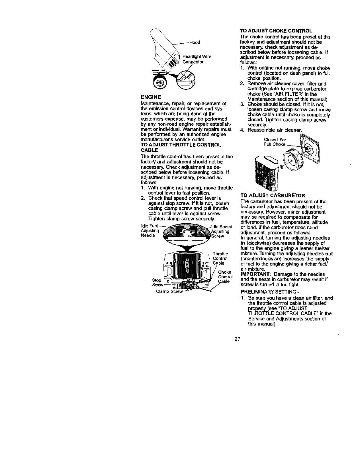
ENGINE
Maintenance,repair,orreplacementof
theemissioncontroldevicesandsys-
tems,whicharebeingdoneatthe
customers expense, may be performed
by any non-med engine repair establish-
ment or individual.Warranty repairs must
be performed by an authorized engine
manufacturer's service outlet.
TO ADJUST THROTTLE CONTROL
CABLE
The throttlecontrolhas been preset at the
factory and adjustment should not be
necessary. Check adjustment as de-
scdbed below before loosening cable. If
adjustment is necessary, proceed as
follows:
1. With engine not running, move throttle
controllever tofast position.
2. Check that speed control lever is
against stop screw. If it isnot, loosen
casing clamp screw and pull throttle
cable untillever is against screw.
Tighten clamp screw securely.
Adjusting
Needle
Throttle
Control
Cable
Stop
Sare_
Cramp
Control
CabLe
TO ADJUST CHOKE CONTROL
The choke controlhas been preset at the
factory and adjustment shoutdnot be
necessary, check adjustment as de-
scribedbelow before loosening cable. If
adjustment is necessary, proceed as
follows:
1. With engine notrunning, move choke
control (located on dash panel) to full
choke position.
2. Remove air cleaner cover, filter and
cartddge plate to expose carburetor
choke (See "AIR FILTER" in the
Maintenance section of this manual).
3. Choke should be closed. If it isnot,
loosen casing clamp screw and move
choke cable untilchoke is completely
closed. Tighten casing clamp screw
securely.
4. Reassemble air cleaner.
Closed For
Full
TO ADJUST CARBURETOR
The carburetor has been present at the
factory and adjustment should not be
necessary. However, minor adjustment
may be required to compensate for
differences in fuel, temperature, altitude
or load. if the carburetor does need
adjustment, proceed as follows:
In general, turning the adjusting needles
in (clockwise)decreases the supplyof
fuel to the engine giving a leaner fuel/air
mixture. Tuming the adjusting needles out
(counterclockwise) increases the supply
offuel to the engine giving a richer fuel/
air mixture.
IMPORTANT: Damage to the needles
and the seats in carburetor may result if
screw is turned in tootight.
PRELIMINARY SETTING -
1. Be sure you have a clean air filter, and
the throttle control cable is adjusted
propedy (see =TOADJUST
THROTTLE CONTROL CABLE"in the
Service and Adjustmentssection of
this manual).
27
2. Withengineofftumidlefueladjusting
needlein(clockwise)closingitfinger
tightandthenturnout(counterclock-
wise)1turn.
FINALSETTING-
1. Start engine and allow to warm for five
minutes. Make final adjustments with
engine running and shift/motion
control lever in neutral (N) position.
NOTE: The highidle is set at the factory
and cannot be adjusted,
2. Id|e s_ed settina - With throttle
control lever in slow position, engine
should idle at 1200 RPM. If engine
idles tooslow or fast, turn idle speed
adjusting screw in or out until correct
idle is attained.
3. Idle fuel needle settina - With throttle
control lever in slow position, turn idle
fuel adjusting needle In (clockwise)
until engine speed decreases and
then turn out (counterclockwise)
approximately 3/4 tam to obtain the
best lowspeed performance.
4. Recheck idle speed. Readjust if
necessary.
ACCELERATION TEST -
5. Move throttlecontrol leverfrom
fast position. If engine hesitates
dies, turn idle fuel adjustingne_
out (counterclockwise) 1/8 turn,
Repeat test and continueto adj
necessary, until engine acceler
smoothly.
High speed stop isfactory adjuste(
not adjust-damage may result.
IMPORTANT: Never tamper with tl
engine governor,which isfactory s
proper engine speed, Overspoedin,
engine above the factory high spee
setting can be dangerous. If you thil
engine-governed high speed need
adjusting, contactyour nearest Se_
other qualified service center, whid
proper equipment and experience
make any necessary adjustments.
28
immediatelyprepareyour tractor for
storage at the end of the season or ifthe
tractor will not be used for 30 days or
more.
_,CAUTION: Never store the tractor with
gasoline in the tank inside a building
where fumes may reach an open flame or
spark. Allow the engine to cool b_lore
storing in any enclosure.
TRACTOR
Remove mower from tractor for winter
storage. When mower is to be storedfor
a period of time, clean it thoroughly,
remove all dirt, grease, leaves, etc. Store
in a clean, dry area.
1. Clean entire tractor (See "CLEANING"
in the Maintenance section of this
manual).
2. Inspect and replace belts, if necessary
(See belt replacement instructions in
the Service and Adjustments section
ofthis manual).
3. Lubricate as shown in the Mainte-
nance section of this manual.
4. Be sure that all nuts, boltsand screws
are securely fastened. Inspect moving
partsfor damage, breakage and wear.
Replace if necessary.
5. Touch up all rustedor chipped paint
surfaces; sand lightly before painting.
BAI-rERY
• Fullycharge the battery for storage.
• After a pedod of time in storage, battery
may require recharging.
• To help prevent corrosion and power
leakage during long periods of storage,
battery cables should be disconnected
and battery cleaned thoroughly(see
"TO CLEAN BATTERY AND TERMI-
NALS"in the Maintenance section of
this manual).
• After cleaning, leave cables discon-
nected and place cables where they
cannot come in contact with battery
terminals.
• If batteryis removed from tractor for
storage, do notstore battery directly on
concrete or damp surfaces.
ENGINE
FUEL SYSTEM
IMPORTANT: Itis importantto prevent
gum deposites from forming in essential
fuel system parts suchas carburetor, fuel
hose, or tank during storage. Also,
experiance indicates that alcohol
blended fuels (called gasohol or using
ethanol or methanol) can attract moisture
which leads to separation and formation
of acids during storage. Acidic gas can
damage the fuel system of and engine
while in storage.
1. Drain the fuel tank.
2. Start the engine and let itrun until the
fuel lines and carburetor are empty.
• Never use engine or carburetor cleaner
products in the fuel tank or permanent
damage may occur.
• Use fresh fuel next season.
NOTE: Fuel stabilizer is an acceptable
altemative in rninlmizingthe formation of
fuel gum deposits during storage. Add
stabilizer to gasoline in fuel tank or
storage container. Always follow the mix
ratio found on stabilizer container. Run
engine at least 10 minutes after adding
stabilizer to allow the stabilizer to reach
the carburetor. Do not drain the gas tank
and carburetor if using fuel stabilizer.
ENGINE OIL
Drain oil (withengine warm) and replace
with clean engine oil. (See "ENGINE" in
the Maintenance section of this manual).
CYLiNDER(S_
1. Remove spark plug(s).
2. Pour one ounce of oil through spark
plug hole(s) intocylinder(s).
3. Tum ignition key to "START" position
for a few seconds to distributeoil
4. Replace with new spark plug(s),
OTHER
• Do not store gasoline from one season
to another.
• Replace your gasoline can if your can
startsto rust. Rust and/or dirfin your
gasoline will cause problems.
• If possible, storeyour tractor indoors
and cover it to give protectionfrom dust
and dirt.
• Cover your tractor with a suitable
protective cover that does not retain
moisture. Do not use plastic. Plastic
cannot breathe which allows conden-
sation to form and will cause your
tractor to rust.
IMPORTANT: Never covertractor while
engine and exhaust areas are stillwarm.
29
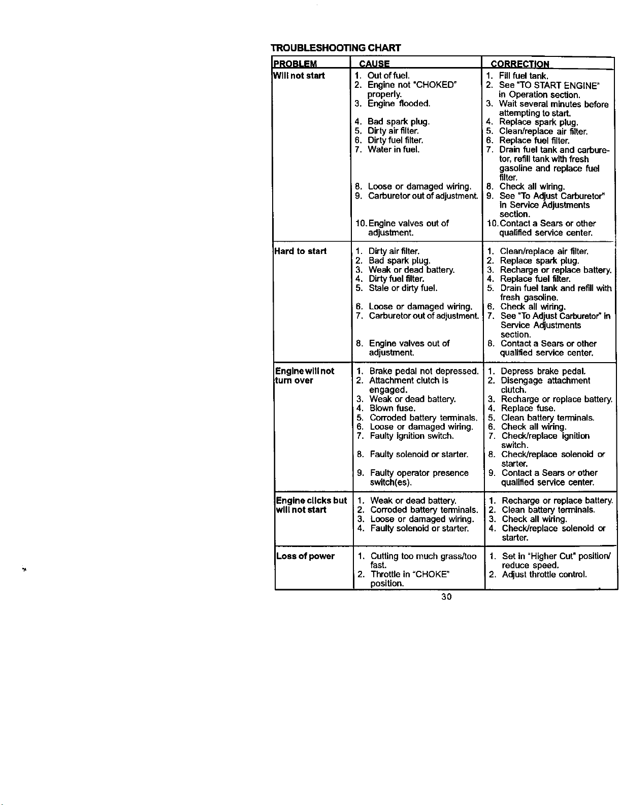
TROUBLESHOOTING CHART
PROBLEM
NIII not start
Hard to start
Englnewlll not
turn over
CAUSE
1. Out offuel.
2. Engine not "CHOKED"
properly.
3. Engine flooded,
4. Bad spark plug.
5. Dirty air filter.
6. Dirty fuel filter.
7. Water infuel.
8. Loose or damaged widng.
9. Carbureter outof adjustment.
10. Engine valves out of
adjustment.
1. Dirty airfilter.
2. Bad spark plug,
3. Weak or dead battery.
4. Dirty fuel filter.
5. Stale or dirtyfuel.
6. Loose or damaged widng.
7, Carburetor out of adjustment.!
8. Engine valves out of
adjustment.
1, Brake pedal not depressed.
2. Attachment clutchis
engaged.
3. Weak or dead battery.
4. Blown fuse.
5. Corroded battery tan_inals.
6. Loose or damaged widug.
7. Faulty ignition switch.
8. Faultysolenoid or starter.
CORRECTION
1. Fillfuel tank.
2. See "TO START ENGINE_
in Operation section.
3, Wait several minutes before
attemptingto start.
4. Replace spark plug.
5. CleaNreplace air filter.
6. Replace fuel filter.
7. Drain fuel tank end carbure-
tor, refilltank with fresh
gasoline and replace fuel
filter.
8. Check all widng.
i 9. See =ToAdjust Carburetor"
in Service Adjustments
section.
10.Contact a Sears or other
qualified service center.
1. Clean/replace air filter.
2. Replace spark plug.
3. Recharge or replace battery.
4. Replace fuel filter.
5. Drainfuel tank and refillwith
fresh gasoline,
6. Check all widng.
7. See "To Adjust Carburetor"in
Service Adjustments
section.
8. Contact a Sears or other
qualified service center.
1. Depress brake pedal.
2. Disengage attachment
clutch.
3. Recharge or replace battery.
4, Replace fuse.
5. Clean battery terminals.
6. Check all wiring.
7. Checldreplace ignition
switch.
8. Checldmplace solenoid or
starter.
9. Contact a Sears or other
qualified service center.
9. Faultyoperator presence
switch(es).
-'nglne clicks but 1. Weak or dead battery. 1. Recharge or replace battery.
Jvlllnot start 2. Corroded battery terminals. 2. Clean battery terminals.
3. Loose or damaged widng. 3. Check all widng.
4. Faultysolenoid or starter. 4. Check/replace solenoid or
starter.
Lose ofpower 1. Cutting too much grass/too 1. Set in "Higher Cut"position
fast. reduce speed.
2. Throttle in =CHOKE" 2. Adjust throttle control.
position.
3O
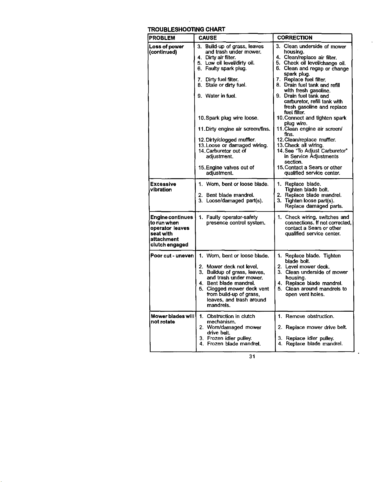
TROUBLESHOOTING CHART
CAUSE CORRECTIONPROBLEM
Loss of power
[continued)
Excessive
vibration
Engine continues
to run when
operator leaves
seat with
attachment
clutch engaged
Poorcut-uneven
Mowerbladeswill
_otrotate
3. Build-upof grass, leaves
and trash under mower.
4. Dirty air filter.
5. Low oil level/dirty oil.
6. Faulty spark plug.
7. Dirty fuel filter.
8. Stale or dirtyfuel.
9. Water infuel.
10.Spark plug wire loose.
11. Dirty engine air screen/fins.
12. Dirty/clogged muffler.
13.Loose or damaged wiring.
14. Carburetor out of
adjustment.
15. Engine valves out of
adjustment.
1. Worn, bent or loose blade.
2. Bent blade mandrel.
3, Loose/damaged part(s).
1. Faulty operator-safety
presence control system.
1. Worn, bent or loose blade.
2. Mower deck not level.
3. Buildupof grass, leaves,
and trash under mower.
4. Bent blade mandrel.
5. Clogged mower deck vent
from build-up of grass,
leaves, and trash around
mandrels.
1. Obstructionin clutch
mechanism.
2. Worn/damaged mower
drive belt.
3. Frozen idler pulley.
4. Frozen blade mandrel.
3. Clean underside of mower
housing.
4. Clean/replace air filter.
5. Check oil level/change oil.
6. Clean and ragap or change
spark plug.
7. Replace fuel filter.
8. Drain fuel tank and refill
with fresh gasoline.
9. Drain fuel tank and
carburetor, refilltank with
fresh gasoline and replace
fuel filter.
10.Connect and tighten spark
plug wire.
11.Clean engine air screen/
fins.
12.Cleardreplace muffler.
13.Cbeck all wiring.
14.See =ToAdjust Carburetor"
in Service Adjustments
section.
15.Contact a Sears or other
qualified service center.
1. Replace blade.
Tighten blade bolt.
2. Replace blade mandrel.
3. Tighten loose part(s).
Replace damaged parts.
1. Check wiring, switches and
connections. If notcorrected,
contact a Sears or other
qualified service center.
1. Replace blade. Tighten
blade bolt.
2. Level mower deck.
3. Clean underside of mower
housing.
4. Replace blade mandrel.
5. Clean around mandrels to
open vent holes.
1. Remove obstruction.
2. Replace mower ddve belt.
3. Replace idler pulley.
4. Replace blade mandrel.
31
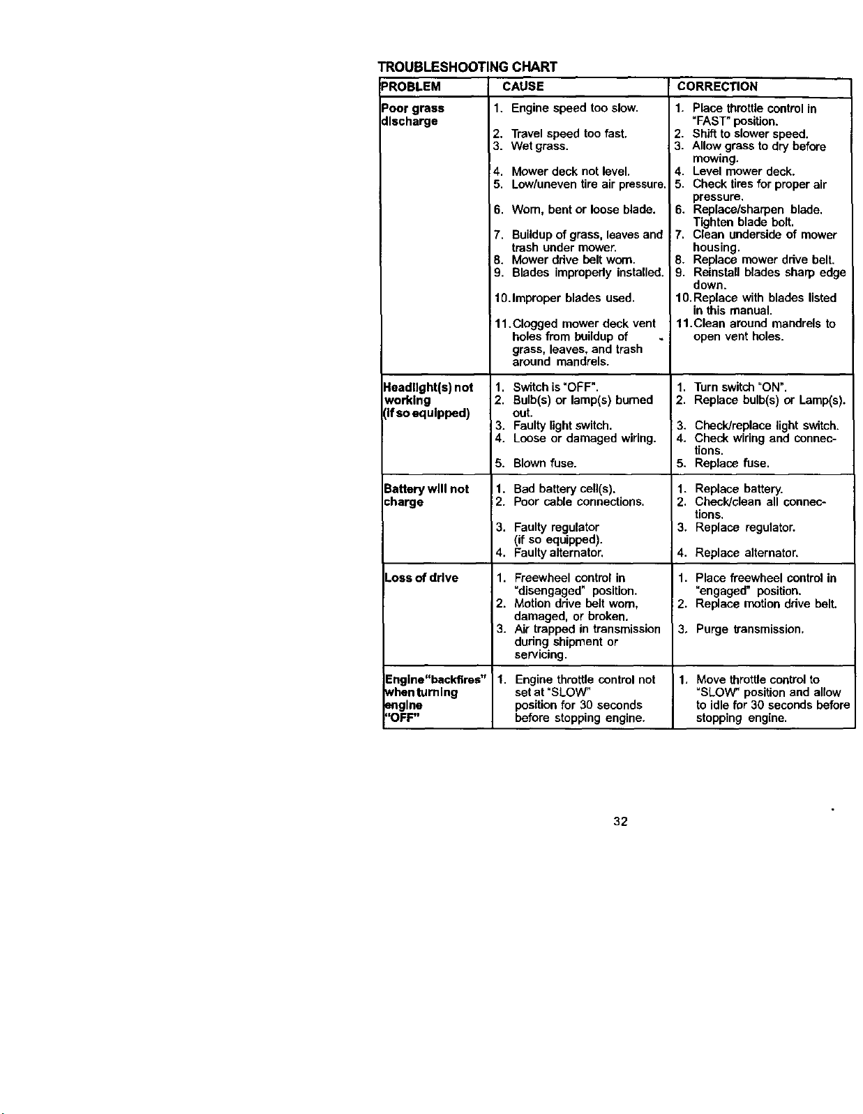
TROUBLESHOOTINGCHART
PROBLEM CAUSE
Poorgrass 1. Enginespeedtooslow.
discharge
2. Travelspeedtoofast.
3. Wet grass.
4. Mower deck not level,
5. Low/uneven tire air pressure.
6. Warn, bent or loose blade.
7. Buildup of grass, leaves and
trash under mower.
8. Mower ddve belt worn.
9. Blades impropedy installed.
lO.Improper blades used.
11 .Clogged mower deck vent
holes from buildup of
grass, leaves, and trash
around mandrels.
•leadllght(s) not
working
Ifso equipped)
3artery will not
:harge
Loss of drive
1. Switch is"OFF".
2. Bulb(s) or lamp(s) burned
out.
3. Faulty light switch.
4. Loose or damaged wiring.
5. Blown fuse.
1. Bad battery cell(s).
2. Poor cable connections.
3. Faulty regulator
(if so equipped).
4. Faultyalternator.
1. Freewheel control in
=disengaged" position.
2. Motion drive holt worn,
damaged, or broken.
3. Air trapped in transmission
during shipment or
servicing.
CORRECTION
1. Place throttlecontrol in
=FAST"position.
2. Shiftto slower speed,
3. Allow grass to dry before
mowing,
4. Level mower deck.
5. Check tires for properair
pressure.
6. Replace/sharpen blade.
Tighten blade bolt.
7. Clean underside of mower
housing.
8. Replace mower drive belt.
9. Reinstall blades sharp edge
down.
10. Replace with blades listed
in this manual.
11. Clean around mandrels to
open vent holes.
1. Turnswitch "ON".
2. Replace bulb(s) or Lamp(s).
3. Check/replace light switch.
4. Check wiring and connec-
tions.
5. Replace fuse.
1. Replace battery.
2. Check/clean all connec-
tions.
3. Replace regulator.
4. Replace alternator,
1. Place freewheel control in
"engaged" position.
2, Replace motiondrive belt.
3. Purge transmission.
Engine"backfires" 1. Engine throttle control not 1. Move throttle control to
whenturning set at "BLOW" "SLOW" position and allow
engine position for 30 seconds to idlefar 30 seconds before
"OFF" before stopping engine, stopping engine.
32
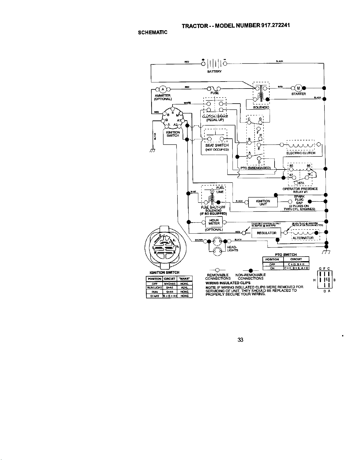
TRACTOR- - MODEL NUMBER 917.272241
SCHEMATIC
I BAITESRY
AMMETER
OPTIONAL)
IGNITION SWITCH
poSmON CIRCUIT ,*MAKE"
OFF M_I_AI NONE
STAKJ B÷S+AI NONE
I_ N/UGItT B*A1 _.L
NI/N _.AI I_INE
FUSE
....... t
CLUTCH / BRAKE
(PEDAL UP)
, i
SEAT SWITCH
(NOTOCCtJpfED)
STARTER
i.... i
_,C Gi
I , i
, _O I
i , F
bB q i . i
__ ELECTRIC CLUTCH
,
OPERATOR PRESENCE
RELAy #1
i FUEL i
i
i i
_d_SOUENC40_RUT'OFF]
(IF SO EQUIPPED)
(o PT_C,t,_,L) , ........ ,
HEAD- I
L_ _H'rs PrOSwi'rcl_
FOal'lION ORCLIIT
OFF C*_G_B÷ H
_ ON C+F,B+E_A÷D G F C
REMOVABLE NON-REMOVABLE
CONNECTIONS CONNECTIONS H B
WtRING INSULATED CUPS
NOTE: IF WIRING INSULATED CLIPS WERE REMOVED FOR
SERVICING OF UNIT, THEY SHOULD BE REPLACED TO O A
PROPERLY SECURE YOUR WIRING.
33
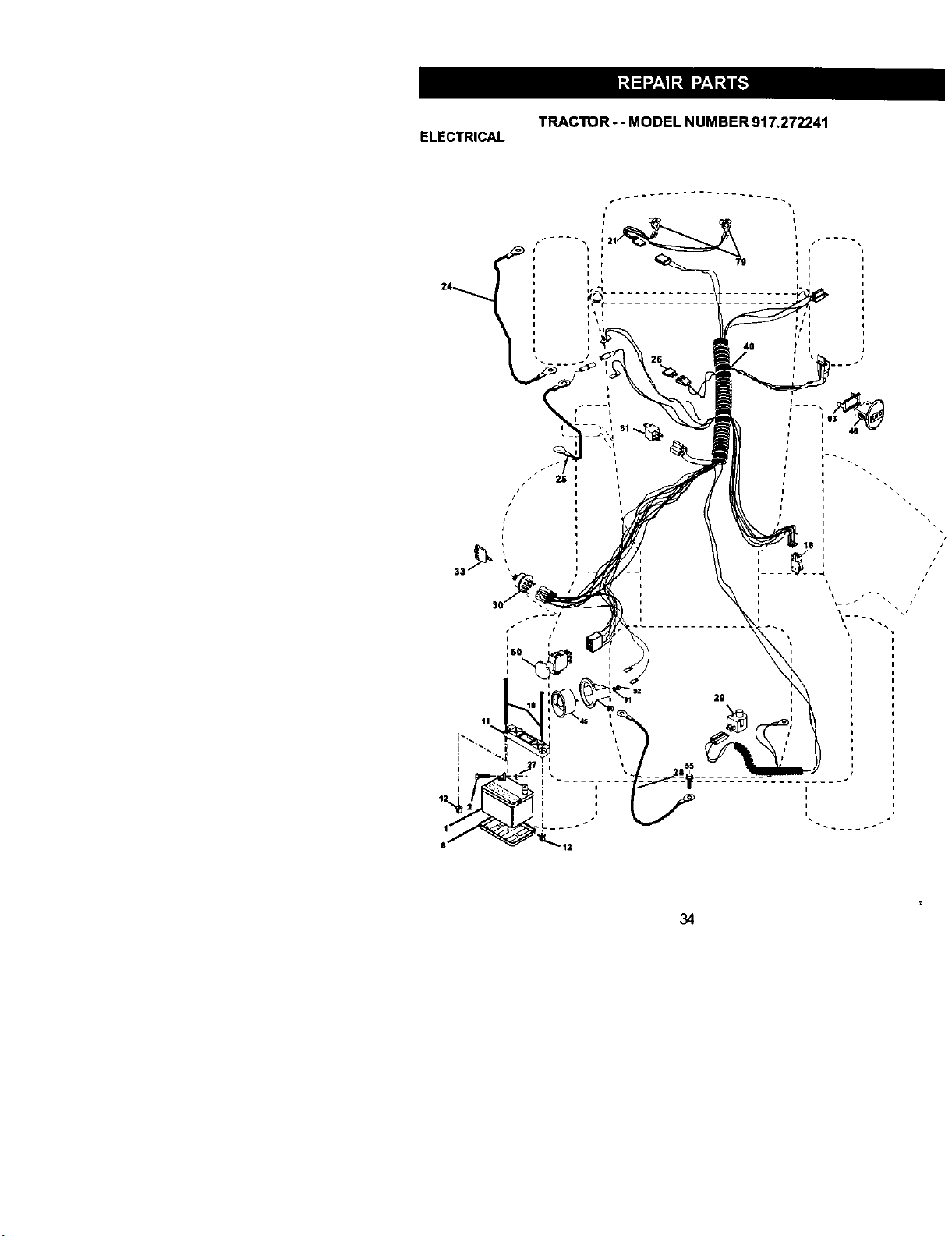
TRACTOR- - MODEL NUMBER 917.272241
ELECTRICAL
i
i
i
29
i
i
i
34
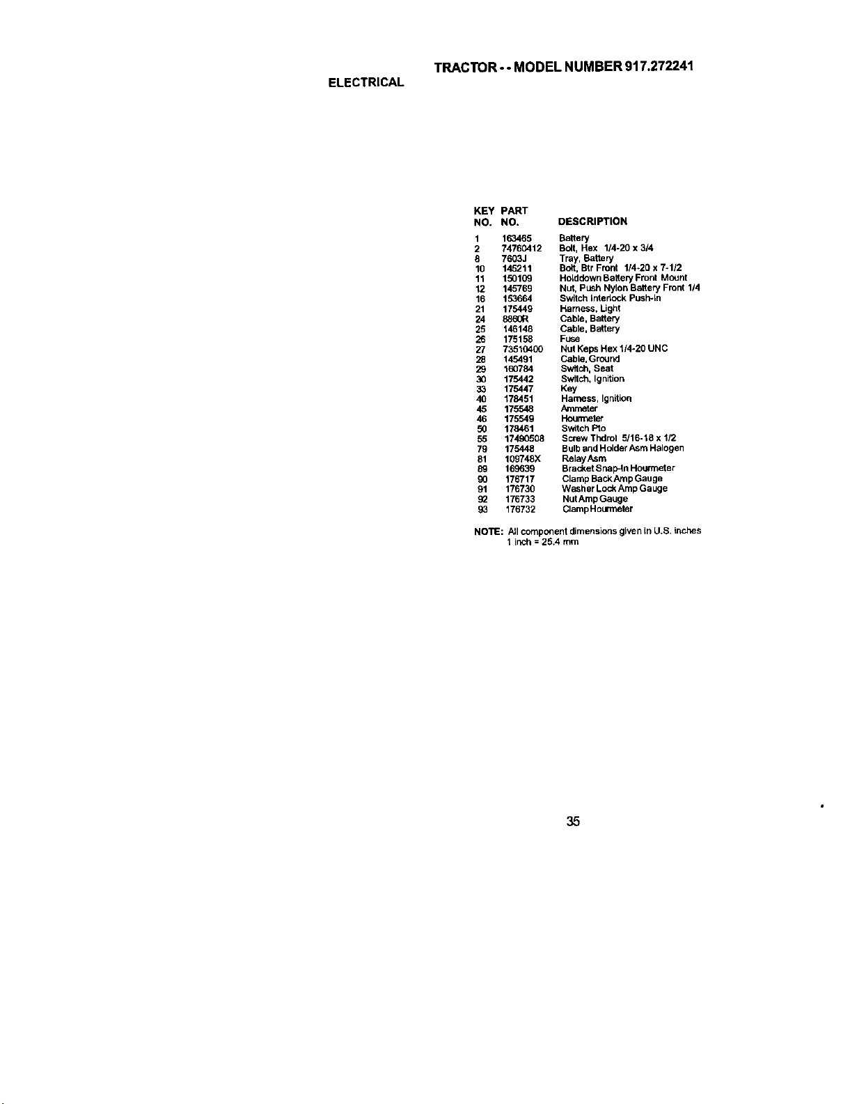
TRACTOR-- MODEL NUMBER 917.272241
ELECTRICAL
KEY PART
NO. NO, DESCRIPTION
1 163465 Battery
2 74760412 Bolt, Hex 114-20 x 3/4
8 7603J Tray, Battery
10 145211 Bolt, Btr Front 114-26 x 7-1/2
11 150109 Holddown BaBery Front Mount
12 145768 Nut, Push Nylon Battery Front 114
16 153664 Switch Interlock Push-in
21 175449 Harness, Ught
24 8860R Cable, Battery
25 146148 Cable, Battery
26 175158 Fuse
27 73510400 Nut Keps Hex 114-20 UNC
28 145491 Cable, Ground
29 160784 Switch, Seat
30 175442 Switch, Ignition
33 175447 Key
40 178451 Harness, Ignition
45 175548 Ammeter
46 175549 Hourmeter
50 178461 Switch lifo
55 17490508 SCOW Thdrol 5/16-18 x 112
79 175448 Bulb and Holder Asm Halogen
81 109748X RelayAsm
89 169639 Bracket Snap-In Hourmeter
90 176717 Clamp BackAmp Gauge
91 176730 Washer Loc_ Amp Gauge
g2 176733 NutAmp Gauge
93 176732 ClampHourmeter
NOTE: All component dimensions given LnU,S. inches
1 inch = 25,4 mm
35
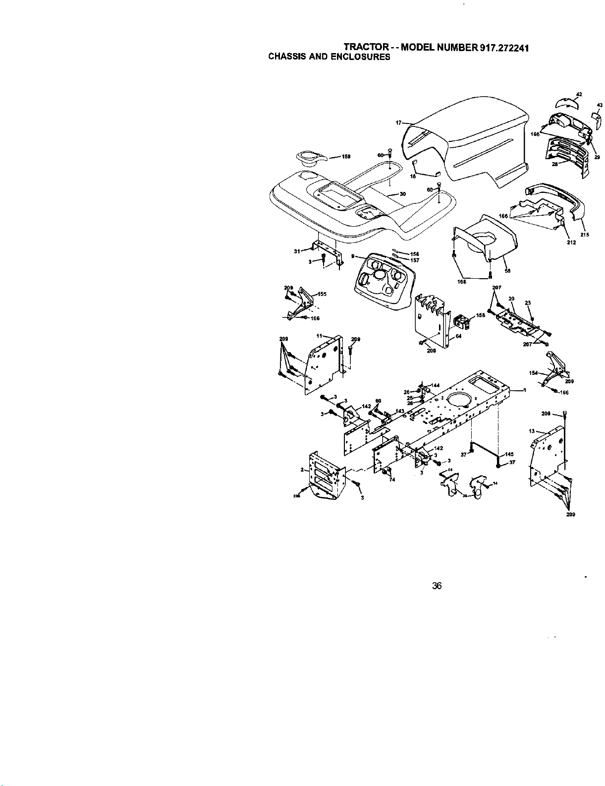
TRACTOR-- MODEL NUMBER 917.272241
CHASSISAND ENCLOSURES
42
23
20g
36

TRACTOR- - MODEL NUMBER 917.272241
CHASSIS AND ENCLOSURES
KEY PART
NO. NO. DESCRIPTION
1
2
3
9
11
13
14
17
18
2O
23
25
26
28
29
3O
31
37
38
42
43
58
59
6O
64
74
142
143
144
145
154
155
156
157
158
159
166
206
2o7
209
212
215
174619
176554
17060612
172542X418
174996
175256X010
17490608
172540X615
126_38X
156437
124028X
19131312
STD541437
174945X418
174944X418
175692X615
139976
17490508
175710
Chassis
Drawb_
Screw, 3/6-16 x 3/4
Dash
Panel, Dash, LH
Panel, Dash, RH
Screw Thdrol 3/8-16 x 1/2
Hood Assembly
BumperHood
Plate Battery
BushlugSnap
Washer 13/32 x 13116 x 12 Gauge
Locknut, Hex, with Insert 3/6-16 UNC
Griile
LightboxDual
Fender/Footrest
Bracket, Fender/Support
Screw, Thdrol. 5/16-18 x 1/2 TYT
Bracket Asrn PIVOtMower Rear
172545)(599 Lens Lh
172544X599 Lens Rh
174993 Duct Hood
110436X Bushing, Snap, Split
STD533707 Bolt Rdhd Sqnk 3/8-16 UNC x 3/4
174997 Dash Lower
STD541437 NutCrowotock3/8-16 UNC
175702 PlateReinforcement
154966 Bracket Swayhar Chassis
175582 Bracket Footrest
156524 Rod Pivot Chassls_Hood
174679 Bracket Dash Rh
174680 Bracket Dash Lh
163805 Striker Plate
163806 Magnet YTGT
162037 Parking Brake Bkrt
155123X418 CLIphelderStl BIk
164863 HWHDH;*Lo. #13-16 x3/4
170165 Bolt Shoulder 5116-18
17670508 Screw Thdrol 5/16-18 x tl2
17000612 Screw Hexwsh Thdr 3/8-16 x 3/4
174988 Bracket Pivot Hood
172543X615 Bumper
NOllE: All component dimensions given in U.S. inches
1 inch = 25.4 mm
37
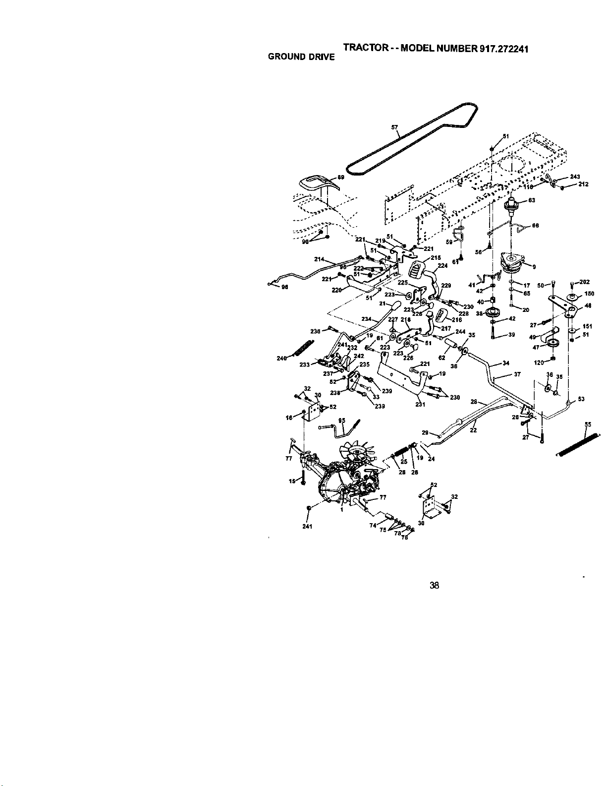
TRACTOR- - MODEL NUMBER 917.272241
GROUNDDRIVE
26 26
241 74 30
38
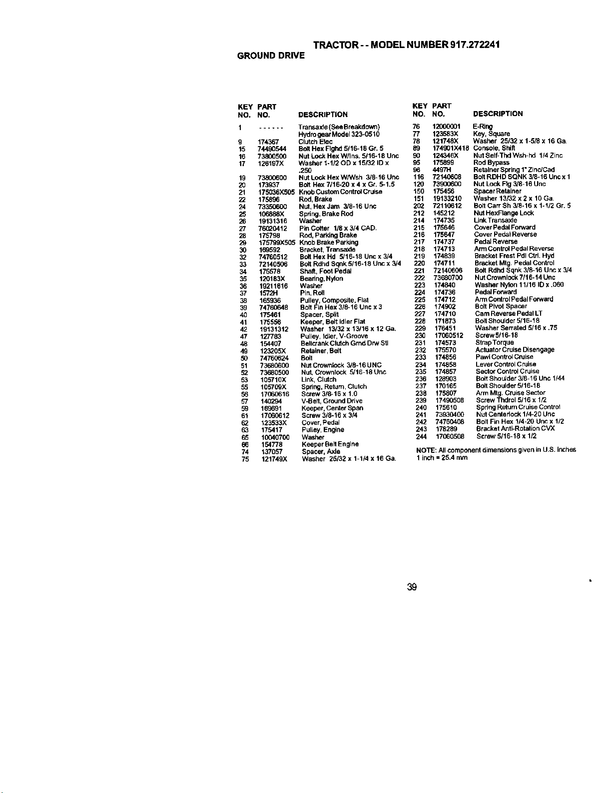
TRACTOR--MODELNUMBER917.272241
GROUNDDRIVE
KEY PART KEY pART
NO. NO. DESCRIPTION NO. NO. DESCRIPTION
1 ...... Transakie (See Breakdown) 76 12000001 E-PJng
Hydrogear Model 323-0510 77 123583X Key, Square
9 174367 Clutch Elec 78 121748X Washer 25/32 x 1-5/8 x 16 Ga,
15 74490544 Bolt Hex Flghd 5/16-18 Gr. 5 89 174001X418 Console, Bhil_
16 73800500 Nut Lonk Hex W/Ins. 3/16-18 Unc 90 124346X Nut Belf-Thd Wsh-hd 1/4 Zinc
17 126197X Washer 1-1/20D x 15/32 ID x 95 175899 Rod Bypass
.250 00 4497H Retainer Spring 1"Zinc/Cad
19 73800600 NutLockHexWhNsh 315`16Unc 116 72140608 BOltRDHDSQNK3/8-16Uncx1
20 173937 Bo5 Hex 7/15`20 x 4 x Gr. 5-1.5 120 73900600 Nut Lock Fig 3/8-16 Unc
21 175_6X505 KnobCustomControlCruise 150 175456 BpacerRetalner
22 175896 Red, Brake 151 19133210 Washer 13/32 x 2 x 10 Ga,
24 73350600 Nut, HexJam 3/6-16Unc 202 7211(;612 BoltcarrBh3/8-16x1-1/2Gr. 5
25 1C6888X Bpnng, Brake Rod 212 145212 Nut HexFlange L_ck
26 19131316 Washer 214 174735 Link Transaxle
27 76_20412 PinCutter I/8x3/4CAD, 215 175646 CoverPedaIForward
28 175798 Rod, Parking Brake 216 175647 Cover Pedal Reverse
29 175799X505 KnohBrakeParking 217 174737 PedalReverse
30 169592 Bracket, Transakie 218 174713 Arm Control Pedal Reverse
32 74760512 Bolt Hex Hd 5/16-18 Unc x 3/4 219 174839 Bracket Frest Pdl Ctd. Hyd
33 72146506 Bolt Rdhd Sopk 5116-18 Unc x 3/4 220 174711 Bracket Mtg, Pedal Control
34 175578 Shaft, Foot Pedal 221 72140606 Bolt Rdhd Sqnk 3/8-16 Unc x 3/4
35 120183X Bearing, Nylon 222 73680700 NUt Crownlock7116-14 Unc
36 19211616 Washer 223 174840 Washer Nylon 11/16 ID x .066
37 157_H Pin, Rdl 224 174736 pedal Forward
38 165936 Pulley, Composite, Flat 226 174712 ArmControl Pedal Forward
39 74760648 Bolt Fin Hex 3/8-16 Unc x 3 226 174902 Bolt Pivot Spacer
40 175461 Spacer, Split 227 174710 Cam Reverse POdolLT
41 175556 Keepar, Belt Idler Flat 228 171873 BoBShoulder 3/15-18
42 19131312 Washer 13/32 x 13/16 x 12 Ga. 229 176451 Washer Serrated 5/16 x .75
47 127783 Pulley, IdLer,V-Groove 230 17060512 ScrewS/16-15
48 154407 Bollctank Clutch Grnd Drw Stl 231 174573 StrapTorque
49 123205X Retainer, Belt 232 175576 Actuator Crolse Disengage
50 74760624 Bolt 233 174856 pawl Control Cruise
51 73680600 NutCrowniock 3/8-16UNC 234 174858 LeverControlCruise
52 73680500 Nut, Crownlonk 5/16-16 Unc 235 174857 Sector Control Cruise
53 105710X Link, Clutch 236 128903 Bolt Shoolder 3/8-16 Unc 1/44
55 105709X Spring, Return, Clutch 237 170165 Bolt Shoulder 5116-18
56 17060616 Scl_=w3/8-16 x 1.0 238 175807 Arm Mtg, Cruise Sector
57 140294 V-Belt, Ground Ddve 239 17490508 Screw Thdrol 5/16 x 1/2
59 16_691 Keeper, Centar Span 240 175610 Spdng Return Cruise Controt
61 17060612 Screw 3/8-16 x 3/4 241 73930400 Nut Centariock 1/4-20 Une
62 123533X Cover, Pedal 242 74760408 Bolt Fin Hex 1/4-20 uric x 112
63 175417 PulLey,Engine 243 178289 Branket Anti-Rotation CVX
65 10040700 Washer 244 17060508 Screw 5116-18 x 112
66 154778 Keepar Belt Engine
74 137057 Spacer, Axle NOTE: All component dimensions given in U.S. inches
75 121749X Washer 25132 x 1-1/4 x 16 Ga. 1 inch = 25.4 turn
39
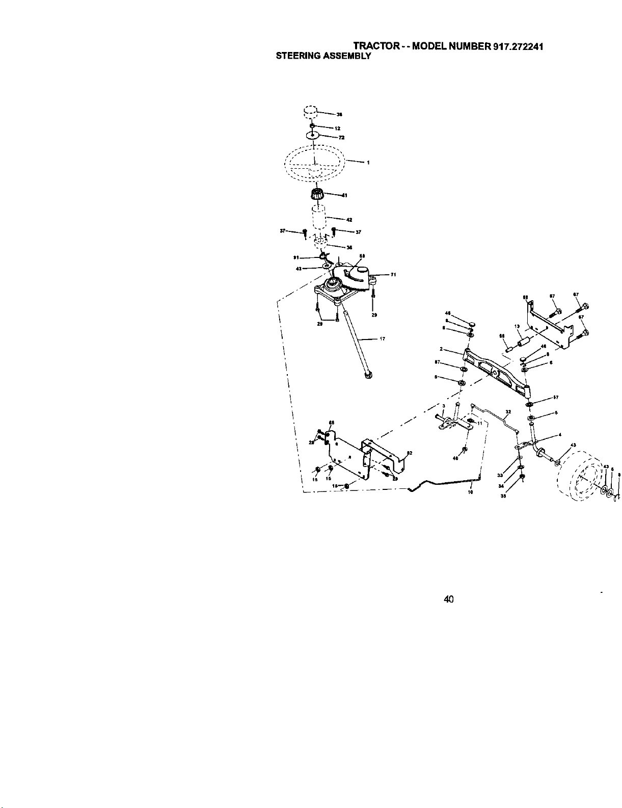
STEERINGASsEMTLP_ycTOR-- MODEL NUMBER 917,272241
40

TRACTOR - - MODEL NUMBER 917.272241
STEERINGASSEMBLY
KEY PART
NO. NO. DESCRIPTION
1
2
3
4
5
6
8
10
11
12
13
15
17
29
32
33
34
35
36
37
38
4O
41
42
43
46
65
67
68
71
72
82
87
88
91
175139)(418 Steedng Wheel
172393 Axle Assembly
169840 Spindle Assembly, LH.
169839 Spindle Assembly, R.H.
6266H Bearing, Race, Thrust, Hardened
121748X Washer 25/32 x 1-5/8 x 16 Gauge
120(X_29 Ring, Klip
175121 Draglink
STD551137 Washer, Lock
73940800 Nut Hex Jam Toplock 1/2-20 Unf
136518 Spacer B_gAxle Front
145212 Nut Hexflange Lock
177883 shaft Assembly, Steering
17060612 Screw, 3/8-16 x 3/4
176162 Rod,Tie
19111216 Washer 11/32 x 3/4 x 16 Ga.
STD551131 Washer Lock Hvy Spr, 5/16
73540500 Crownlock Nut 5/16-24 Unf
155105 Bushing,Steering
152927 Screw
175140X418 Insert, Steering Wheel
STD541537 Nut Lock Center 5/8-24 Unf
159945 Adaptor, Steering Wheel
174530X418 Boot, Steering Shefl
121749X Washer 25/32 x 1-1/4 x 16 Gauge
121232X Cap,SpindLe
160367 Spacer Brace Axle
72140618 Bolt Rdhd Sq 3/8-16 UNC x 2-1/4
169827 Axte, Brace
175146 SteedngAsm
19182411 Washer 5/16 Id x 1-1/2Od 11 G Zin
169835 Bracket Susp Chassis Front
173966 Washer Flat .781 x 1-1/2 x .14
175118 Bolt Sheulder 7/16-20 Unc
175553 ClipSteering
NOTE: All component dimensions given in U.S. Inches
1 inch = 25.4 mm
41
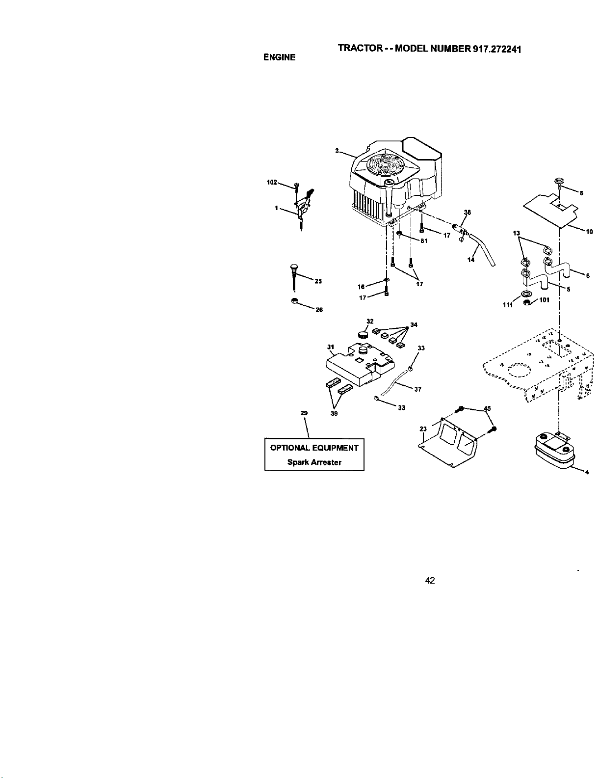
TRACTOR-- MODEL NUMBER 917.272241
ENGINE
14
32
29\ 39 _,_
OPTIONAL EQUIPMENT
Spark Attester
• i
I
42
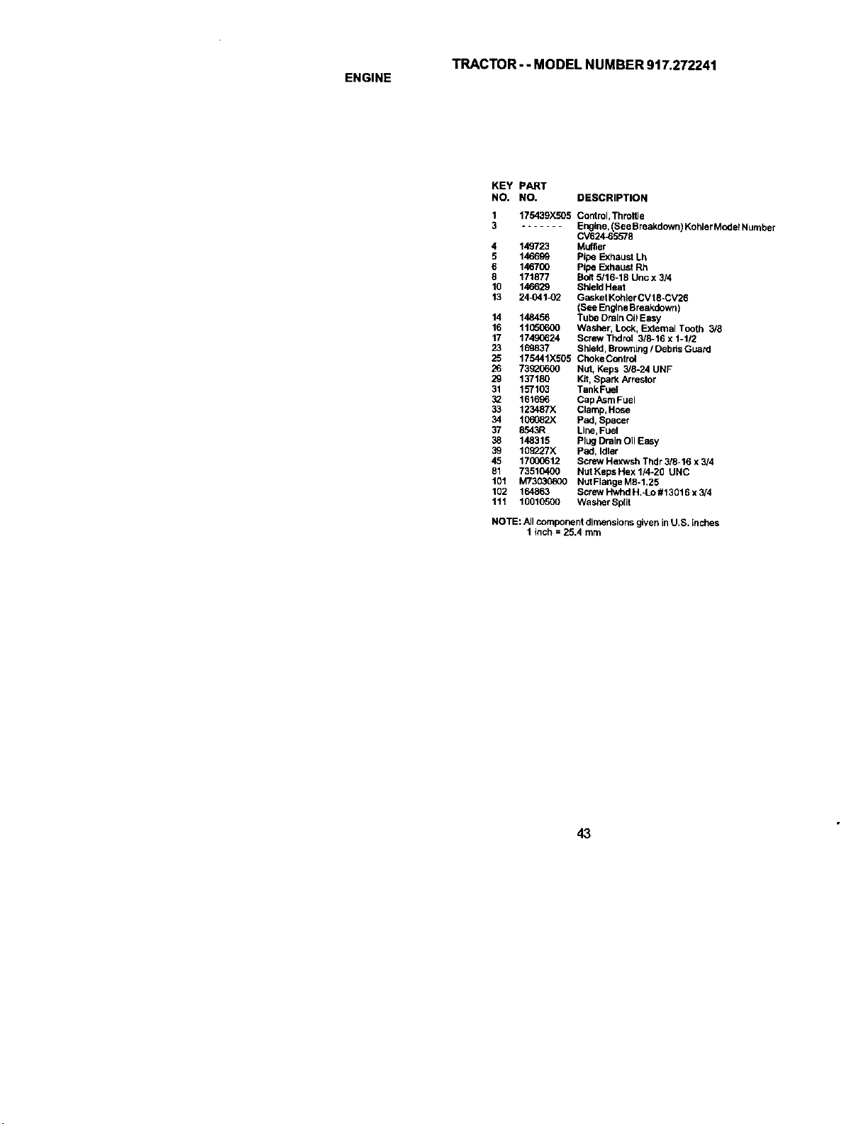
TRACTOR- - MODEL NUMBER 917.272241
ENGINE
KEY PART
NO. NO. DESCRIPTION
1 175439X505 Control, Throitle
3 ....... Engine, (See Breakdown) Kohler Model Number
CV624-65578
4 149723 Muffler
5 146699 Pipe Exhaust Lh
6 1467CO Pipe Exhaust Rh
8 171877 Bolt 5/16-18 Unc x 3/4
10 146629 ShdeldHeat
13 24_41_2 Gasket KohlerCV18-CV26
(See EngineBreakdown)
14 148456 Tube Drain Oi_Easy
16 11_600 Washer, Lock, External Tooth 3/8
17 17490624 Screw Thdrol 3/8-16 x 1-112
23 169837 Shield, Browniug / Debds Guard
25 175441X505 ChokeControl
26 73_0600 Nut, Keps 3/8-24 UNF
29 137180 Kit, Spark Arrestor
31 157103 TankFuel
32 161696 CapAsrn Fuel
33 123487X Clamp, Hose
34 I06082X pad, Spacer
37 8543R Line, Fuel
38 148315 Plug Drain Oil Easy
39 10_/X Pad, Idler
45 17000612 Screw Hexwsh Thdr 3/8-16 x 3/4
81 73510400 Nut Keps Hex 1/4-20 UNC
101 M73030800 NutFlangeMSo1.25
102 164863 Screw Hwhd H,°Lo # 13016 x 3/4
111 10010500 Wesber Split
NOTE: All component dimensions given in U.S. inches
1 Inch = 25.4 mm
43
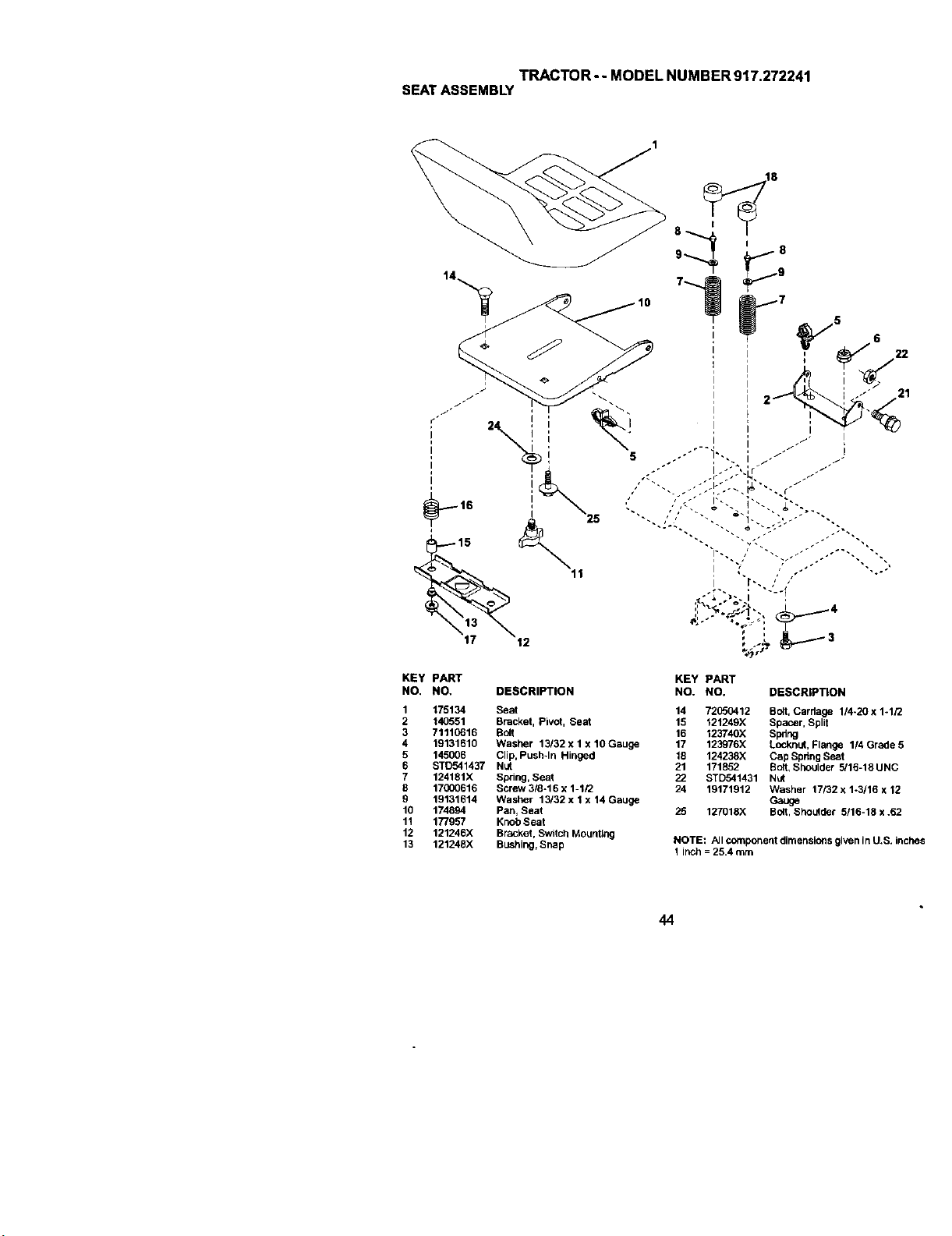
TRACTOR - - MODEL NUMBER 9t7.272241
SEATASSEMBLY
KEY PART KEY PART
NO. NO, DESCRIPTION NO. NO, DESCRiPTiON
1 175134 Seat 14 72050412 Bolt, Carriage 114-20 x 1-1/2
2 140551 Bracket, Pivot, Seat 15 121249X Spacer, Split
3 71110616 Bolt 16 123740X Spring
4 19131610 Washer 13/32 x 1 x 10 Gauge 17 123976X Locknat, Flange 1/4 Grade 5
5 145006 Clip, Push*In Hinged 18 124238X Cap Spdng Seat
6 ST0541437 Nut 21 171852 Bo8, Shoulder 5116-18UNC
7 124181X Spring, Seat 22 STD541431 Nut
8 17000616 Screw 3/8-16 x 1-1/2 24 19171912 Washer 17/32 x 1-3/16 x 12
9 19131614 Washer 13/32 x 1 x 14 Gauge Gauge
10 174894 Pan, Seat 25 127018X Bolt, Sheufder 5/16-18 x .62
11 177957 Knoh Seat
12 121246X Bracket, Switch Mounting
13 121248X Bushing,Snap NOTE: AJIcomponent dimensions given in U,S. Inches
1 inch = 25.4 mm
44
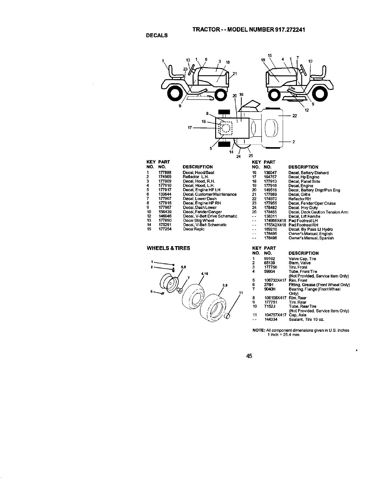
TRACTOR-- MODEL NUMBER 917.272241
DECALS
1\ 13 18
14
24
KEY PART KEY PART
NO, NO. DESCRIPTION NO, NO.
1 177888 Decal, Hood/Seat 16 138047
2 174969 Reflector LH. 17 164757
3 177909 Decal, Hood, R.H. 18 177913
4 177910 Decal HOOd,LH. 19 177918
5 177917 Decal, Engine HP LH 20 149516
6 133644 Decal_Customer Matnter_nce 21 177889
7 177967 Decal, Lower Dash 22 174970
8 177916 Decal, Engine HP RH 23 177955
9 177967 Decal, Dash Lower 24 178482
10 156439 Decal, FenderDanoer 25 178455
12 146046 Decal, V-Belt Ddve Scherr_tlc - - 138311
13 177890 Decal StrgWheel -- 174998)<418
14 175291 Decal, V-Belt Schematic =- 175542X418
15 177254 Decal Replc -- 169210
- - 178495
- - 178496
WHEELS &TIRES
25
15 7
18 10
\
9
12
KEY PART
NO. NO.
1 59192
1 _ 2 65139
3 177750
=---'--_ _'s 7 4.1o 4 5_eo4
. (__- ;_3,9 765 106732X4179040H278H
6 11
_/ 8 106108X417
, 9 177751
IO 7152J
11 104757X417
- - 144334
DESCRIPTION
Decal, Bagery Oiehsrd
Decal, Hp Engine
Decal, Panel Side
Deca_,Engine
Decal, Batter/Dngr/Psn Eng
Decal, Gdlle
Reflector RH
Decal, Fender Oper Cruise
Decal, Hvy Duty
Decal, Deck Caution Tension Arm
Decal, Lift Handle
pad Footrest LH
Pad Footrest RH
Decal, By Pass U Hydro
Owner's Manual, English
Owner's Manual, Spanish
DESCRIPTION
Valve Cap, Tire
Stem, Valve
Tire, Front
Tube, Front Tire
(Not Provided, Service Item Only)
Rim, Front
Fitting, Grease (Front Wheel Only)
Bearing, Flange (FrontWheel
Only)
Rim, Rear
]'ire, Rear
Tube, Rear Tire
(Net Provided, Service Item Only)
Cap, Axle
Sealant, Tire 10 oz.
NOllE: Allcomponent dimensions given in U.S. inches
1 tnch= 25.4 mm
45
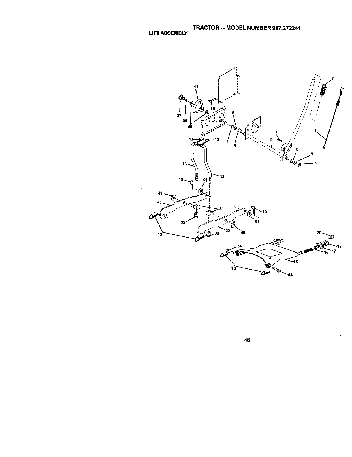
TRACTOR-- MODEL NUMBER 917.272241
LIFTASSEMBLY
37
38
4O
41
! .s
/ /
/ /
/ /
/ /
48

TRACTOR-- MODEL NUMBER 917.272241
LIFTASSEMBLY
KEY PART
NO. NO, DESCRIPTION
1 176263 PlungerAssembly
2 159476 Shaft Assembly, Lilt
3 138284 Pin, Groove
4 120_0002 E-PJng
5 19211621 Washer 21132 x 1 x 21 Gauge
6 120183X Bearing, Nylon
7 175830 Grip, Handle, Fluted
11 175370 Link, Lift, L,H.
12 175371 Link, LJft,R.H.
13 4939M Retainer Spring
15 175562 Plate Asrn Suspension Front
16 73350800 Nut Jam Hex 1/2-13 Unc
17 175689 Trunnion FrontSusp,
10 73800800 Nut Lock w(Wsh 1/2-13 Unc
20 163552 Retainer Spdng
31 176205 Trunion Sups. Arm,
32 175994 Nut Lift Link 7/16-20
36 155697 Pointer Height Indicator
37 123935X Plug Hole
38 17060516 Screw 5116-18 x 1
40 19112410 Washer 11132 x 1-1/2 x 10 Ga
41 155098 Indicator Height Stlt
49 145212 Nut Hex/La_ge Lock
51 19171416 Washer 17/32 x 7/B x 16 Ga.
52 175378 Arm Suspension Rear LH
53 175802 Arm Suspension Rear RH
54 175560 Pin Flange
NOTE: All component dimensions given in US inches
1 inch = 25,4 mm
47
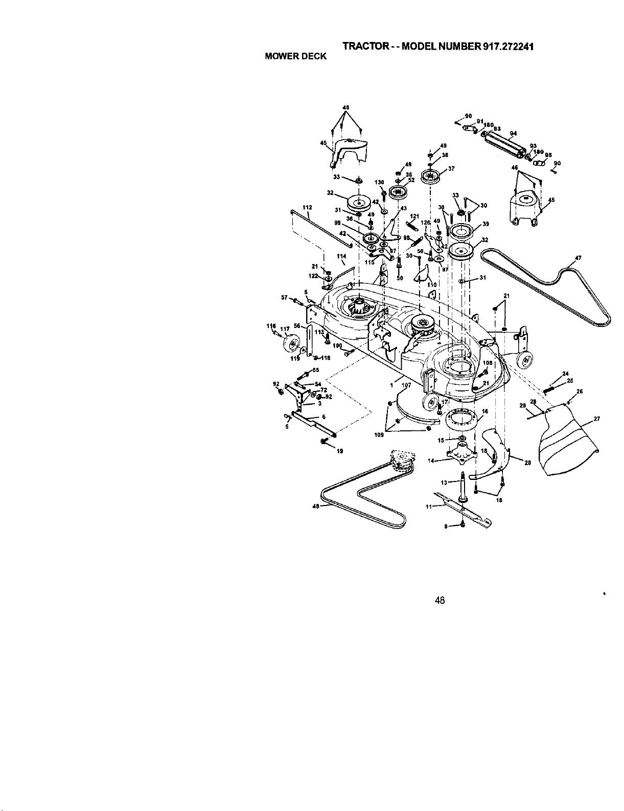
TRACTOR-- MODEL NUMBER 917.272241
MOWERDECK
112
I
47
24
18
48
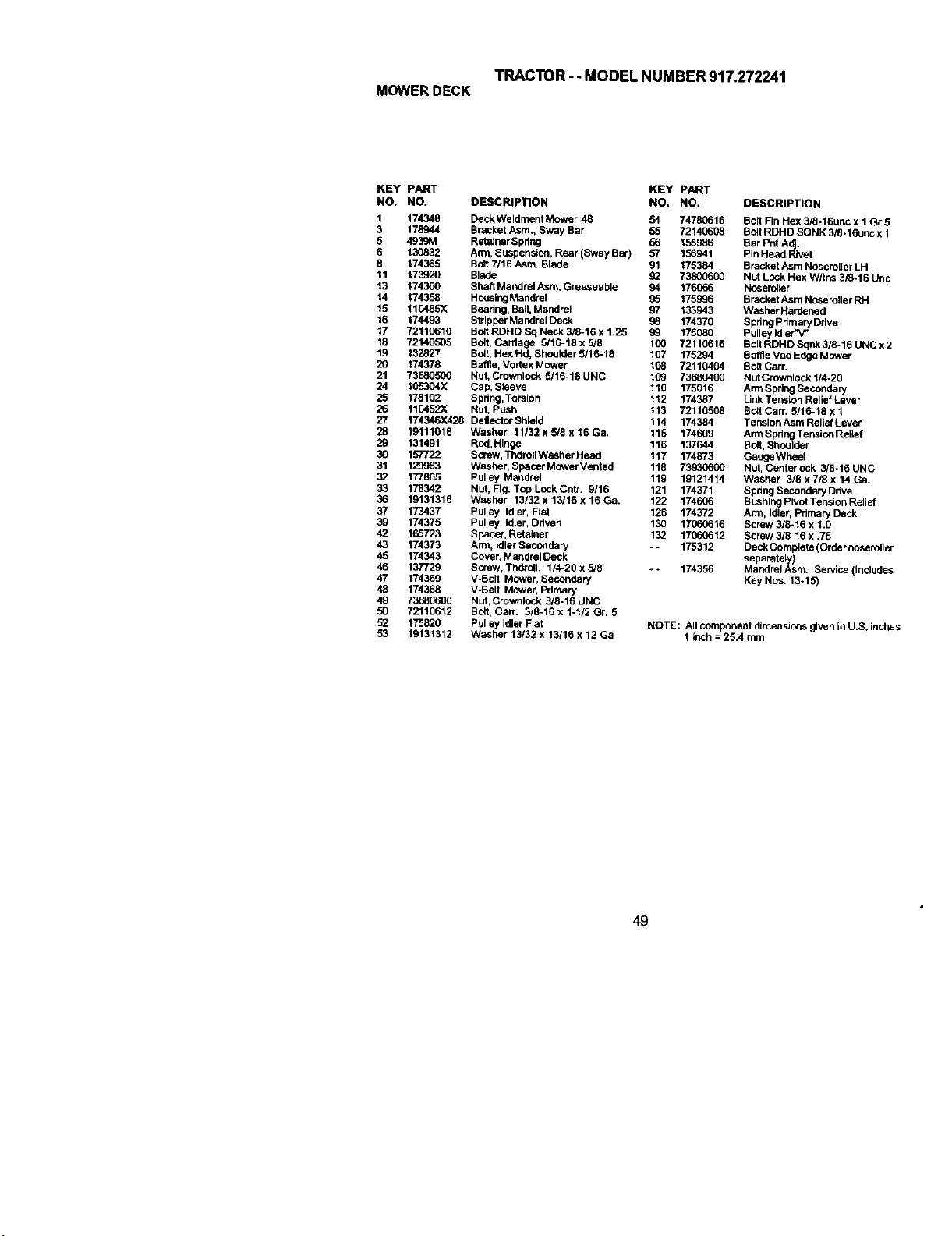
TRACTOR--MODELNUMBER917.272241
MOWERDECK
KEY PART KEY PART
NO. NO. DESCRIPTION NO. NO, DESCRIPTION
1 174348 DeckWeldrnent Mower 48 54 74780616 Bolt Fin Hex 3/8-16unc x 1 Gr 5
3 178944 Bracket Asm., Sway Bar 55 72140608 BoltRDHD SONK 3/_-16unc x 1
5 4996M RetolnerSpring 56 155986 Bar Pnt Adj.
6 130832 Arm, Suspension, Rear (Sway Bar) 57 156941 Pin Head Rivet
8 174365 Bolt 7/16 Asm. Blade 91 175384 Bracket Asm Noseroller LH
11 173220 Blade _ 73800600 Nut Lock Hex W/Ins 3i8-16 Unc
13 174360 Shaft Mandrel Asm. Greaseable 94 176066 Noseroller
14 174358 HousingMandrel 96 175996 BracketAsm Nc_eroller RH
15 110485X Beadng, Ball, Mandrel 97 133943 Washar Hardened
16 174493 Slrlpper Mandrel Deck 96 174370 Spdng Pdmary Ddve
17 7211(:610 Bolt RDHD Sq Neck 316-16 x 1.25 99 175080 Pulley Idler"V"
18 72140505 Bolt, Carriage 5/16-18x5/6 100 72110616 BoltRDHDSqnk3/8*16UNCx2
19 132827 BoB, Hex Hd, Shoulder 5/16-18 107 175294 BatrieVac Edge Mower
20 174378 Baffle, Vodex Mower 108 72110404 Bolt Carr,
21 73680500 Nut, Crownlock 5/16-18 UNC 109 73960400 NutCrownlock 114-20
24 105304X Cap, Sleeve 110 175016 ArmSpring Secondary
25 178102 Spring, Torsion 112 174387 LinkTensLon Relief Lever
26 110452)( Nut, Push 113 72110508 BoBCam 5/16-18 x 1
27 174346X428 DellectorShleld 114 174384 TenslonAsmRellefLever
28 19111016 Washer 11/32xS/Sx16Ga. 115 174609 ArmSpdngTensionRolief
29 131491 Rnd,Hinge 116 137644 Bolt, Shoulder
30 157722 Screw, ThdroUWasher Head 117 174873 GaugeWheel
31 129963 Washar, Spacer Mower Veated 118 73930600 Nut, Canteriock 3/8-16 UNC
32 177865 Pulley, Mandrel 119 19121414 Washer 3/8 x718 x 14 Ca.
33 178342 Nut, Fig. Top LockCntr. 9/16 121 174371 Spdng SecondaryDdve
36 19131316 Washer 13/32 x 13/16 x 16 Ca. 122 174606 BushingPivot Tension Roller
37 173437 Pulley, Idler, Flat 126 174372 Ann, Idler, Primary Deck
32 174375 Pulley, Idler, Driven 130 17660_16 Screw 3/6-16 x 1.0
42 165723 Spacer, Retainer 132 17060612 Screw 3/6-16 x .75
43 174373 Arm, Idler Secondary -- 175312 Deck Carnplete (Order noseroller
45 174343 Cover, Mat_drelDeck separately)
46 137729 Screw, Thdroll. 1/4-20 x 5/8 - - 174396 Mandrel Asm, Se_ice {Includes
47 174369 V-Belt, Mower, Secondary Key Nos. 13-15)
48 174368 V-Belt, Mower, Primary
49 73960600 Nut, Crownlock 3/8-16 UNC
96 72110612 BOdlCan'. 318-16 x 1-112 Gr. 5
5_ 175826 Pulley Idler Flat
53 19131312 Washer 13/32 x 13116 x 12 Ca
NOTE: All component dimensions given inU.S. Inches
1 inch = 25A mm
49
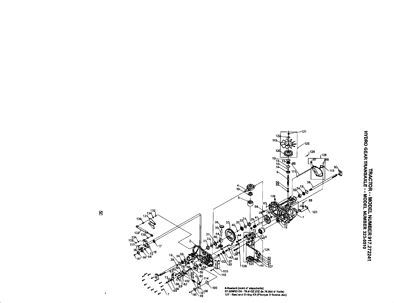
.124
6-Sealant (Jolt d"etRr_he4te)
S7-20WSO Oil - 78,80Z (OZ de 70.820 d' Huile)
127 ° Seal randO_ng Kit (Phoquo 0 Sonne Jeu)
128
88
123
m
,,4
I
oO
zr
;0m
_m
_.n -.4
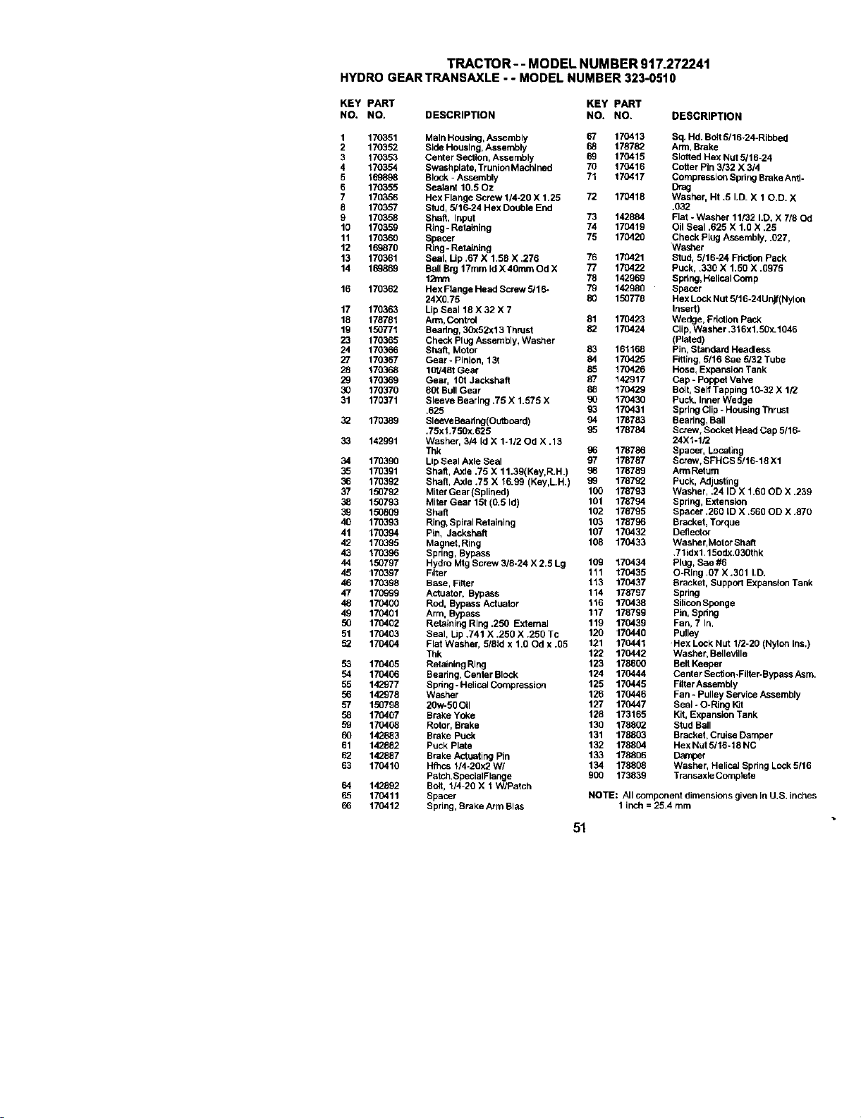
TRACTOR- - MODEL NUMBER 917.272241
HYDROGEARTRANSAXLE. - MODELNUMBER323-0510
KEY PART KEY PART
NO. NO. DESCRIPTION NO. NO. DESCRIPTION
1 170351 Main Housing, Assembly 67 170413 Sq. Hd. Bait 5/15-24-Ribbed
2 170352 Side Housing, Assembly 6B 178782 Arm, Brake
3 170353 Center Section, Assembly 69 170415 SIo6ed Hex Nut5/16-24
4 170354 Swashplate, Truaion Machined 70 170416 Coger Pin 3/32 X 3/4
5 169898 Block-Assembly 71 170417 Compression Spdng Brake Anti-
6 170355 Sealant 10,50z Drag
7 170356 Hex Flange Screw 114-20 X 1.25 72 170418 Washer, Ht .5 I.D. X 10,D. X
8 170357 Stud, 5/16-24 Hex Double End .932
9 170358 Shaft, Input 73 142884 Flat - Washer 11/32 I.D. X 7/60d
10 170359 Ring- Retaining 74 170419 Oil Seal .625 X 1.0 X .25
11 170360 Spacer 75 170420 Check plug Assembly, .027,
12 169870 Ring - Retaining Washer
13 170361 Seal, Up ,67 X 1,58 X .276 76 170421 Stud, 5116-24 FdctJonPack
14 1_869 Ball Brg 17ram IdX 4Omm Od X 77 170422 puck, .330 X 1,50 X .0975
12ram 78 142969 Spdng, Helical Comp
16 170362 Hex Flange Head Screw 5/16- 79 142980 Spacer
24)(0,75 80 150778 HexLock Nut 5/16-24Unjf(Nylon
17 170363 Lip Seal 18X 32 X 7 Insert)
18 178781 Arm, Control 81 170423 Wedge, Friction Pack
19 150771 Beadng, 30x52x13 Thrust _ 170424 CUp, Washer .316x1.50x.1046
23 170365 Check Plug Assembly, Washer (Plated)
24 170366 Shaft, Motor 83 161168 Pin, Standard Headless
27 170367 Gear - Pinion, 131 84 170425 Fitting, 5/16 Sae 5/32 Tube
26 170368 101/48t Gear 85 170426 Hose, Expansio_ Tank
29 170369 Gear, 101 Jackshaft 87 142917 Cap - Poppet Valve
30 170370 601 BullGear 8B 170429 Bolt, Self Tapping 10-32 X 1/2
31 170371 Sleeve Bearing .75 X 1.575 X 90 170430 Puck, Inner Wedge
.625 93 170431 SpringClip - Housing Thrust
32 170389 SleeveBeadng(Outbcard) 94 178783 Bearing, Ball
.75x1.750x,625 95 178784 Screw, Socket Head Cap 5/16-
33 142991 Washer, 3/4 Id X 1-1/20d X .13 24X1-1/2
Thk 96 178786 Spacer, Locating
34 170390 Lip Seal Axle Seal 97 178787 Screw, SFHCS 5/16-18 X1
35 170391 Shaft, Axte .75 X 11.39(Key,R.H.) 98 178789 ArmRetum
36 170392 Shaft, Axle .75 X 16.99 (Key,LH.) 9g 178792 Puck, Adjusting
37 150792 MitorGear(Splined) 100 178793 Washer, .24 ID X 1.60 OD X ,239
38 150793 Miter Gear 15t (0,5 Id) 101 178794 Spring, Extension
39 150809 Shaft 102 178795 Spacer .260 [D X .560 OD X .870
40 170393 Ring, Spiral Retaining 103 176796 Bracket, Torque
41 170394 Pin, Jackshefl 107 170432 Deflector
42 170395 Magnet,Ring 106 170433 Washer, Motor Shaft
43 170396 Spring, Bypass .71idx1,15odx,O30thk
44 150797 Hydro Mtg Screw 318-24 X 2.5 Lg 109 170434 Plug, Sae #6
45 170397 Filter 111 170435 O-Ring ,07 X .301 I,D.
46 170398 Base, Fitter 113 170437 Bracket, Support Expansion Tank
47 170999 Actuator, Bypass 114 178797 Spring
48 170400 Rod, Byp_;s Actuator 116 170438 SiliconSponge
49 170401 Arm, Bypass 117 178799 Pin, 9pdng
50 170402 Retaining Ring .250 External 119 170439 Fan, 7 In.
51 170403 Seal, I.jp .741 X .250 X .250 Tc 120 170440 Pefley
52 170404 Flat Washer, 5/61d x 1.00d x .05 121 170441 Hex Lock Nut 1/2-20 (Nylon Ins.)
Thk 122 170442 Washer, Bellevllle
53 170405 Retaiaing Ring 123 178800 Belf Keepar
54 170406 Bearing, Center Block 124 17(3444 CenterSection-FIIter-BypassAsm.
55 142977 Spdng - Helical Compression 125 170445 FIItor Assembly
56 142978 Washer 126 170446 Fan _ Pulley Service Assembly
57 150798 20w-50 0_1 127 170447 Seal - O-Ring K_t
58 170407 Brake Yoke 128 173165 Kit, Expansion Tank
59 176408 Rotor, Brake 130 178802 Stud Ball
60 142883 Brake Puck 131 178803 Bracket, Cruise Damper
61 142882 Puck plate 132 178804 Hex Nut 5/16-18 NC
62 142887 Brake Actuating Pin 133 178806 Damper
63 170410 Hfhcs 1/4o20x2 W/ 134 178808 Washer, Helical Spring Lock5116
Patch,SpaclaiFlange 900 173839 Transaxle Comptete
64 142892 Bolt, 1/4-20 X 1 W/Petch
65 170411 Spacer NOTS: AIIcomponeutdimensionsgivenlnU,S. inches
66 170412 Spring, Brake Arm Bias 1 inch = 25.4 mm
51
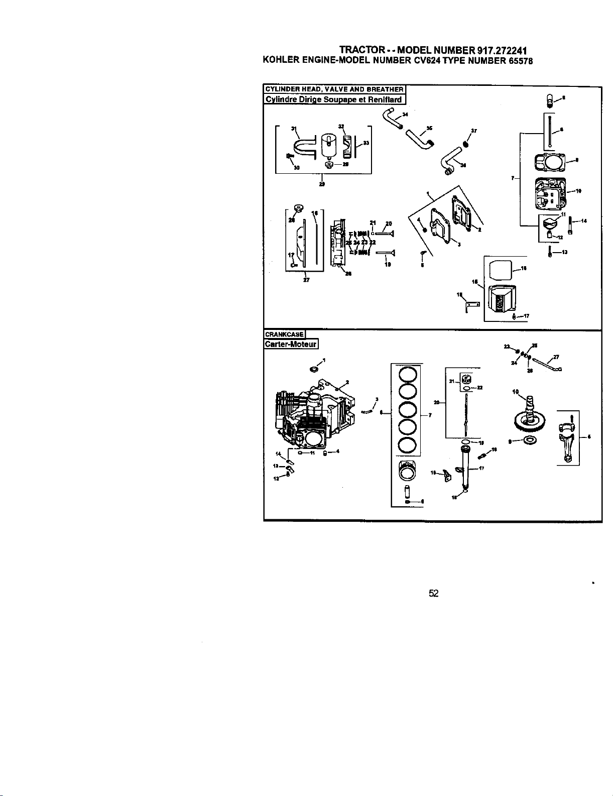
TRACTOR- - MODEL NUMBER 917.272241
KOHLERENGINE-MODELNUMBERCV624TYPE NUMBER65576
=1
CRANKCASEI
;arter-Moteur I
jl
Q
/
I 0--11
52
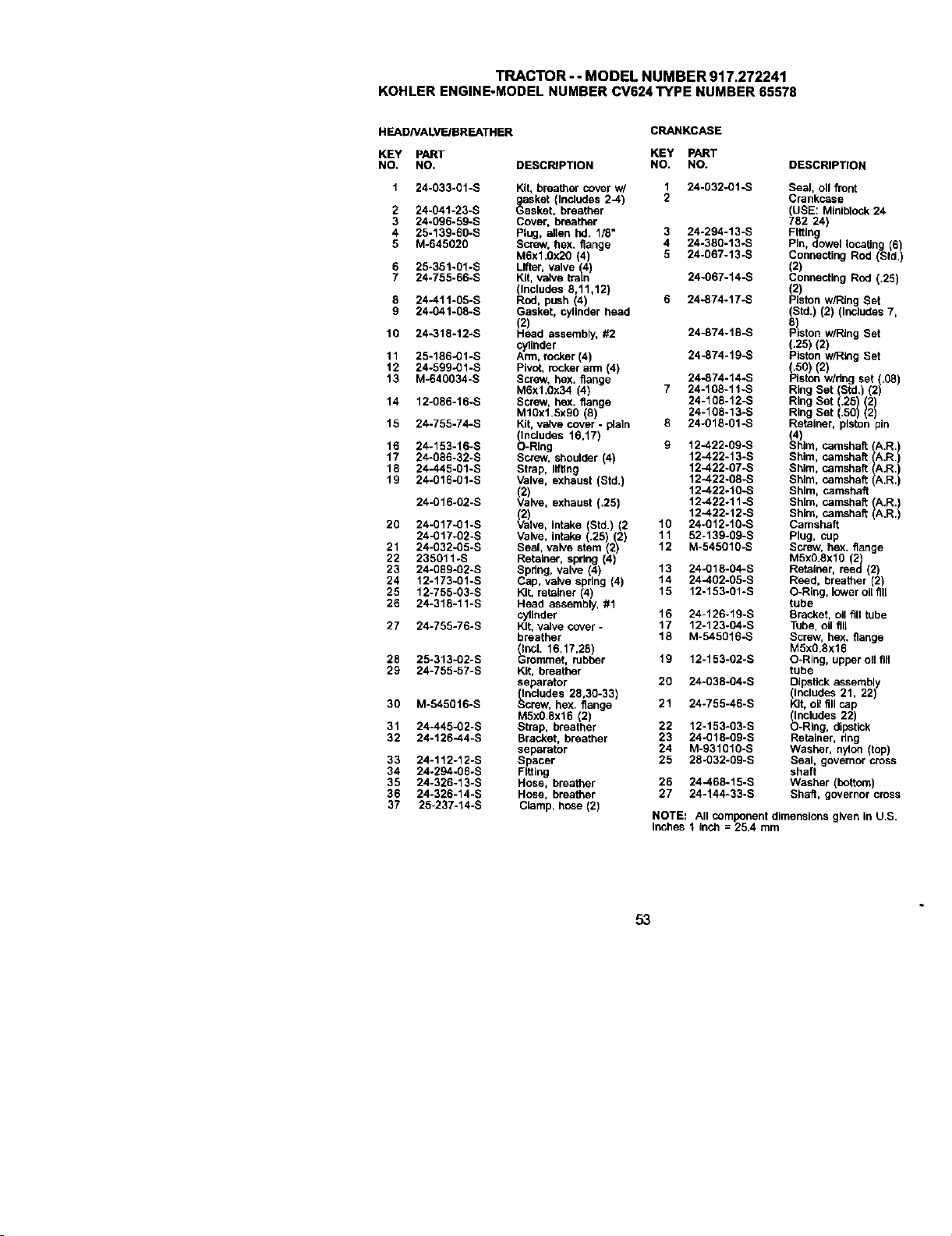
TRACTOR- - MODEL NUMBER 917.272241
KOHLERENGINE-MODELNUMBERCV624TYPE NUMBER65578
HEADNALVF.JBREATHER
CRANKCASE
KEY PART KEY PART
NO, NO. DESCRIPTION NO. NO. DESCRIPTION
2
3
4
5
10
11
12
13
14
15
16
17
18
19
2O
21
22
23
24
25
26
27
28
29
3O
31
32
24-033-01-S Kit, breather cover w/ 1 24-032-01-S Seal, oil front
gasket (Includes 2-.4) 2 Crankcase
24-041-23-S Gasket, breather (USE: Miniblock 24
24-096-59-S Cover, breather 782 24)
25-139-60-S Plug, allen hd. 1/8" 3 24-294-13-S Fitting
M-645020 Screw, hex. flange 4 24-380-13_S Pin, dowel tacaUng (6)
M6x1.0x20 (4) 5 24-067-13-S Connecting Rod (Std)
25-351-01-S Lifter, valve (4 (2)
24-755-66-S Ki, valve treln 24-067-14-S Connecting Rod (.25)
(Includes 8,11,12) (2)
24-411-05-S Rod, push (4) 6 24_874-17-S Piston w/Ring Set
24-041-08-S Gasket, cylinder head (Std.) (2) (Includes 7,
(2) 8
24-318-12-S Head assembly, #2 24-874-18-S P ston w/Ring Set
cylloder (.25) (2)
25-186-01-S Arm, rocker (4) 24-874-19-S Piston w/Ring Set
24-599-01-S Pivot, rocker arm (4) (.50) (2)
M-640034-S Screw, hex. flange 24-874-14.S Piston w/dng set (.08)
M6x1.0x34 (4) 7 24-108-11-S Ring Set (Std.) (2)
12-086-16-S Screw, hex. flange 24-108-12-S Ring Set (.25 (2)
M10x1.Sx90 (8) 24-108-13-S Rng Set (.50 2)
24-755-74-S Kit, valve cover - plain 8 24-018-01-S Retainer, piston pin
(Includes 16,17)
,a_) camshaft A.R,
24-153-16-S O-Ring 9 12-422-09-S him, (
24-086-32-S Screw, shoulder (4) 12-422-13-S Shim, camshaft IA'R
24-445-01-S Strap, lifting 12-422-07.S Shim, camshaft A.R
24-016-01-S Valve, exhaust (Std.) 12-422.08.-S Shim, camshaft (A.R.
(2) 12-422-10-S Shim, camshaft
24-016-02-S Valve, exhaust (.25) 12-422-11-S Shim, camshaft A.R.)
(2) 12-.422-12-S Shim, camshaft A.R.)
24-017-01-S Valve, intake (Std.) (2 10 24-012-10-S Camshaft
24-017-02-S Valve, intake (.25) (2) 11 52-139-09-S Plug, cup
24-032-05-S Seal, valve stem (2) 12 M-545010-S Screw, hex. flange
235011-S Retainer, spring (4) M5x0.Sxl0 (2)
24-089-02-S Spring, valve (4) 13 24-018-04-S Retainer, reed (2)
12-173-01-S Cap, valve spring (4) 14 24-402-05-S Reed, breather (2)
12-755-03-S Kit, retainer (4) 15 12-153-01 -S O-Ring, lower oil fill
24-318-11-S Head assembly, #1 tube
cylinder 16 24-126-19-S Bracket, oil fill tube
24-755-76-S Kit, valve cover - 17 12-123-04-S Tube, oil flu
breather 18 M-545016-S Screw, hex. flange
(Incl. 16,17,28) MSx0.Sx16
25-313-02-S Grommet, rubber 19 12-153-02-S O-Ring, upper oil fill
24-755-57-S Kit, breather tube
separator 20 24-038-04-S DIp_tick assembly
(Includes 28,30-33) (Includes 21, 22)
M-545016-S Screw, hex. flange 21 24-755-46-S Kit, oil fill cap
M5x0.Sx16 (2) (Includes 22)
24-445-02-S Strap, breather 22 12-153-03-S O-Ring, dipstick
24-126-44-S Bracket, breather 23 24-018-09-S Retainer, ring
separator 24 M-931010-S Washer, nylon (top)
24-112-12-S Spacer 25 28-032-09-S Seal, governor cross
24-294-06-S Fitting shaft
24-326-13-S Hose, breather 26 24-468-15-S Washer (bottom)
24-326-14-S Hose, breather 27 24-144-33-S Shaft, governor cross
25-237-14-S Clamp, hose (2)
ROTE: All component dimensions given in U.S.
inches 1 Inch = 25.4 mm
33
34
35
36
37
53
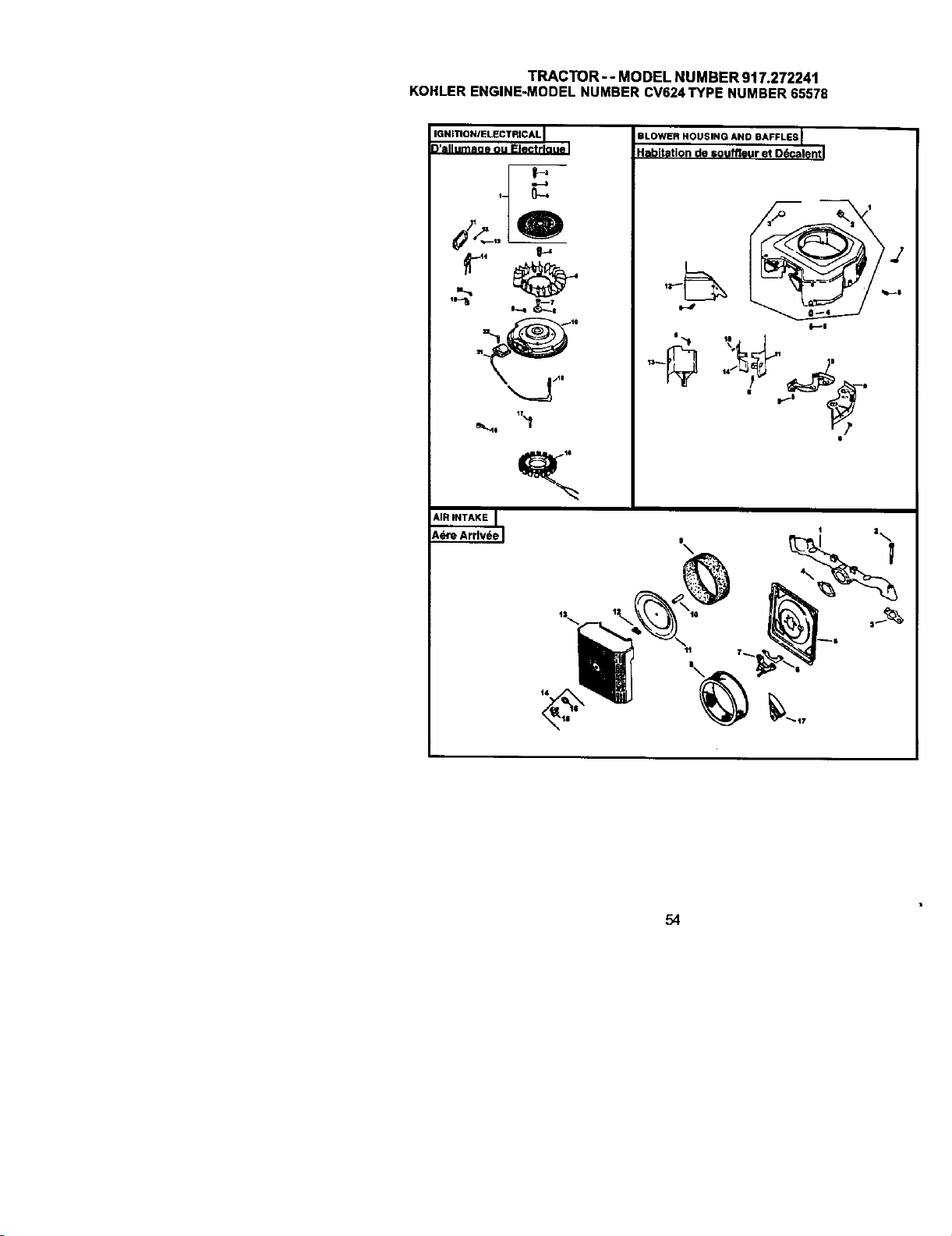
TRACTOR--MODELNUMBER917.272241
KOHLERENGINE-MODELNUMBERCV624TYPENUMBER65578
'Q"mON'EL_C"'C'LI
F-,
BLOWER HOUSING AND BAFFLES I
Habitation de souffleur et D6calentl
t4
54
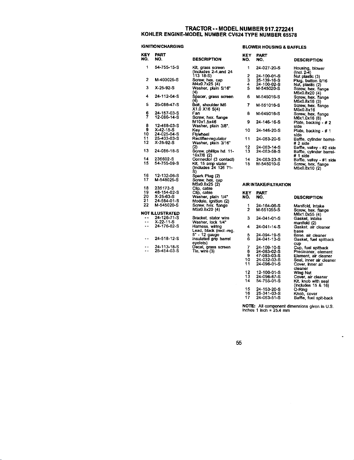
TRACTOR - - MODEL NUMBER 917.272241
KOHLERENGINE-MODELNUMBERCV624TYPE NUMBER65578
IGNITIONICHARGING BLOWER HOUSING & BAFFLES
KEY PART KEY PART
NO. NO. DESCRIPTION NO. NO,
1 54-755-15-B Kit, grass screen 1 24-027-20-S
(Includes 2-4,and 24
113 18-S) 2 24-100-01-S
2 M-403025-S Screw, hex. cap 3 25-13g-16-S
M4x0.7x25 (4) 4 24-100-02-S
3 X-25-92-S Washer, p4ain 5/16" 5 M-545920-S
4 24-112-04-S _acer, grass screen 6 M-545016-S
5 25-g86-47-S Bolt, shoulder M6 7 M-551016-B
Xl.O X16 S(4)
6 24-157-93-S Fan 8 M-645016-S
7 12-686-14-S Screw, hex. flange
Mlgx1.5x46 9 24-146-16-S
8 12-468-03-S Washer, plaLn 3/8".
9 X-42-15-S Key 10 24-146-20-S
10 24-625-04-S Flywheel
11 25-493-03-S Rectifier-regulator 11 24-063-20-S
12 X-25-92-S Washer, plain 3/16"
(2) 12 24-063-14-S
13 24-086-18-S Screw, phillips hd. 11- 13 24-063-58-S
16x7/8 2)
14 236602-S Connector 3 contact 14 24-663-23-S
15 54-755-09-S Kit, 15 am_pstator 15 M-545010-S
(Includes 24 126 71-
S)
16 12-132-06-S Spark Plug (2)
17 M-548625-S Screw, he_. cap
M5x0.8x25 (2) AIR INTAKE/FILTRATION
18 235173-S Clip, cable
19 48-154-02-S Clip, cable KEY PART
20 X-25-63-S Washer, plain 1/4" NO. NO, DESCRIPTION
21 24-584-01-S Module, ignition (2)
22 M-545920-S Screw, hex flange
M5xO.Sx2O (4)
NOT ILLUSTRATED
-- 24-126-71-S Bracket, stator wire
-- X-22-11-S Washer, lock 1/4"
-- 24-176-82-S Harness, widng
Lead, black (rect.-reg.
5" - 12 gauge
insulated grip bar_el
eyelets)
Decal, grass screen
Tie, wire (3)
-- 24-518-12-S
-- 24-113-18-S
- - 25-454-93-S
DESCRIPTION
Housing, blower
(Ind. 2-4)
Nut plastic (3)
Plug, button 9/16
Nut, plastic (2)
Screw, hex. flange
M5xO.8x2O (4)
Screw, hex. flange
MSxO.Sx16 (3)
Screw, hex. flange
M5x0.8x16
Screw, hex. flange
M6x1.Ox16 (6)
Plate, backing - # 2
side
Plate, backing - # 1
side
Baffle, cylinder barrel-
# 2 side
Baffle, valley - #2 side
Baffle, cylinder barrel-
# 1 side
Baffle, vaUey - #1 side
Screw, hex. flange
M5X0.6xl0 (2)
1 24-164-06-S Manifold, Intake
2 M-651055-S Screw, hex. flange
M6x1.0x55 (4)
3 24-g41-01-S Gasket, intake
manifold (2)
4 24-041-14-S Gasket, air cleaner
base
5 24-094-19-S Base, air cleaner
6 24-041-13-S Gasket, fuel spltback
cup
7 24-109-10-S Cup, fuel spltback
8 24-063-02-S PrecJeaner, element
9 47-O83-03÷S Element, air cleaner
10 24-032-03-S Seal, inner air cleaner
11 24-096-01*S Cover, Inner air
cleaner
12 12-106-01-S Wing Nut
13 24_096-67-S Cover, air deaner
14 54-755-01-S Kit, knob with seal
(Includes 15 & 16)
15 24-153-20-S O-Ring
16 25-341-03-S Knob, cover
17 24-063-51-S Baffle, fuel spit-back
NOTE: All component dimensions given in US
inches 1 inch = 25.4 mm
55
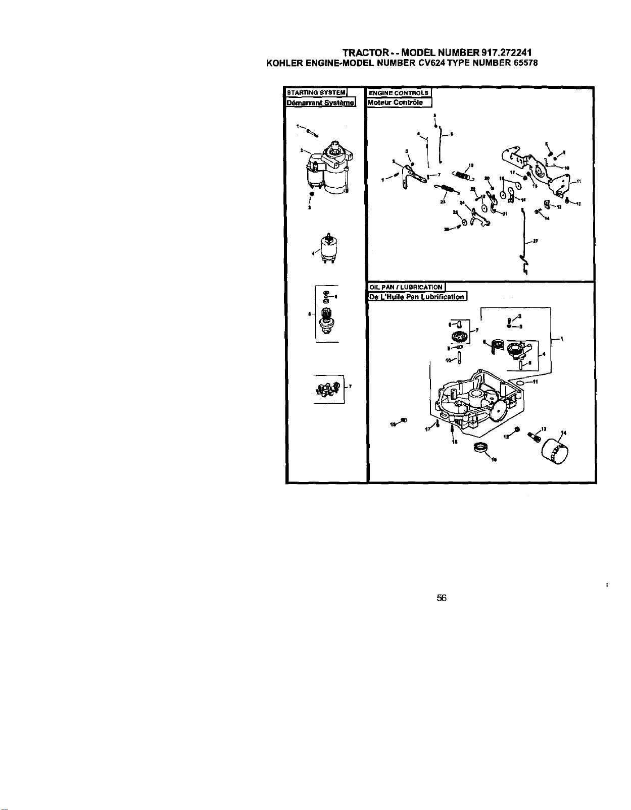
TRACTOR--MODELNUMBER917.272241
KOHLERENGINE-MODELNUMBERCV624TYPENUMBER65578
BTARTING_YSTEM I
_narrant Svstt_mel
!
$
ENGINE CONTROLS
_oteur Contr6Je
t /tl LL.,-',-._ W
I
_27
OIL pAN / LUBRICATION I
De L'Huile Pan Lubdficatlon I
[
D--$
._ _-
3__2_'
56
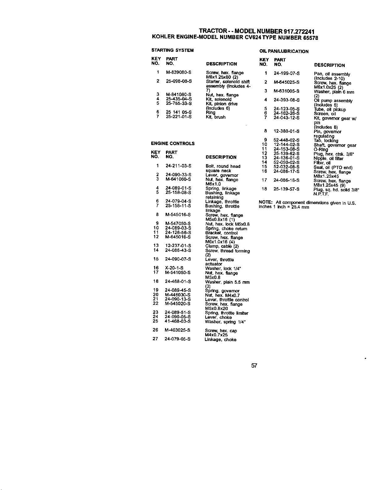
TRACTOR- - MODEL NUMBER 917.272241
KOHLER ENGINE-MODELNUMBERCV624TYPE NUMBER65578
STARTING SYSTEM
KEY PART
NO. NO,
1 M-839080-S
2 25-og8-o8-s
3 M-841080-S
4 25-435-04-S
5 25-755-33-S
6 25 141 05-S
7 25-221-BI-S
ENGINECONTROLS
KEY PART
NO. NO.
1 24-211 -O3-S
2 24-090-33-S
3 M-64106g-B
4 24-089-01-S
5 25-158-08-S
6 24-079-04-S
7 25-158-11-S
8 M-545016-S
g M-547050-S
10 24-089-03-S
11 24-126-56-S
12 M-645016-S
13 12-237-01-S
14 24-086-43-S
15 24-090-07-S
16 X-20-1-S
17 M-541050-S
18 24-468-01 -S
19 24-089-45-S
20 M-446030-S
21 24-090-13-S
22 M-545020-S
23 24-089-51-S
24 24-ggo-05-S
25 4%468-03-S
26 M-403025-S
27 24-079-05-S
OIL PAN/LUBRICATION
KEY PART
DESCRIPTION NO. NO. DESCRIPTION
Screw, hex. flange 1 24-199-07-S
M8xl.25x80 (2)
Starter, sOlenoid shift 2 M-645025-S
assembly (Includes 4-
7) 3 M-631005-S
Nut, hex. flange
Kit, solenoid 4 24-393-08-S
Kit, pinion ddve
_cludes 6) 5 24-123-g5-s
ng 6 24-162-26-S
Kit, brush 7 24-043-12-S
DESCRIPTION
Bolt, round head
square neck
Lever, governor
Nut, hex. flange
M6xl .g
Spnng, tlnkage
Bushing, linkage
retaining
Linkage, throttle
Bushing, throttle
linkage
Screw, hex. flange
M5x0.Sx16 (1)
Nut, hex. lock M5xO.B
Spdng, choke return
Bracket, control
Screw, hex. flange
M6xl.Ox16 4)
Clamp, cable 2
Screw, thread forming
(2)
Lever, throttle
actuator
Washer, lock 114"
Nut, hex, flange
M5x0.B
Washer, plain 5.5 mm
_3p)rlng, governor
Nut, hex. M4xO.7
Lever, throttle control
Screw, hex. flange
MSxg.Sx20
Spring, throttle ,miter
Lever, choke
Washer, spdng 1/4"
Screw, hex. cap
M4xO.7x25
Linkage, choke
12-380-01-S
9 52-448-02-S
10 12-144-02-S
11 24-153-08-S
12 25-139-62-S
13 24-136-g1-B
14 52-0fi0-02-S
15 52-032-g8-s
16 24-086-17-S
17 24-086-16-S
18 25-139-57-S
Pan, ofi aSSembly
(Includes 2-10)
Screw, hex. flange
M6x1.0x25 (2)
Washer, plain 6 mm
(2)
Oil pump assembly
(Includes 5)
Tube, oil pickup
Screen, oil
Kg, governor gear w/
_ln
Includes 8)
Pin, governor
regulating
Tab, locking
Shaft, governor gear
O-Ring
Plug, hex. ctsk. 3/8"
Nipple, oil filter
Filter, c_l
Seal, oil (PTO end)
Screw, he)(. flange
MBx1.25x45
Screw, hex. flange
MSx1.25x45 (9)
Plug, sq. hd. solid 3/8"
N.P.T.F.
NOTE: All component dimensionsgiven in U.S.
Inches1 Inch = 25A, mm
57
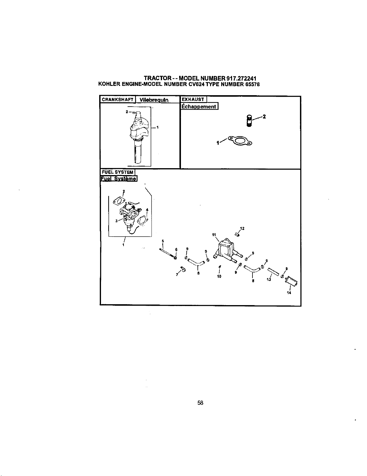
TRACTOR--MODELNUMBER917.272241
KOHLERENGINE-MODELNUMBERCV624TYPENUMBER65578
CRANKSHAFT Vllebrequln
r
L
EXHAUST
I_chaDI3ement I
FUELSYSTEMI
-'uel Svst6mel
/
1
5
1o I8 t_ _
i-_
t4
58
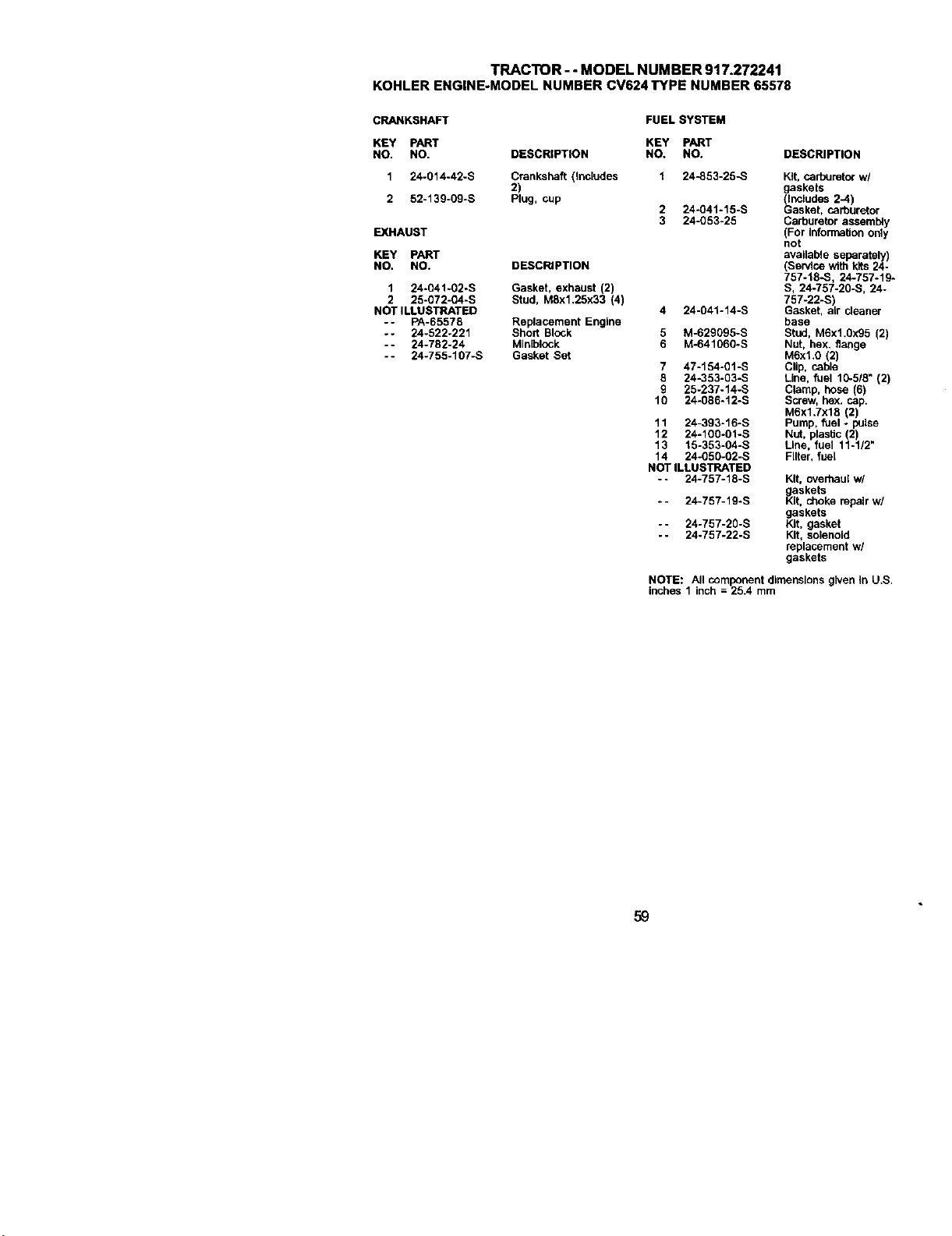
TRACTOR- - MODEL NUMBER 917.272241
KOHLERENGINE-MODELNUMBERCV624TYPE NUMBER65578
CRANKSHAFT
KEY PART
NO, NO.
1 24-014-42-S
2 52-139-09-S
EXHAUST
KEY PART
NO. NO.
1 24-041-02-S
2 25-072-04-S
NOT ILLUSTRATED
- - PA-65578
-- 24-522-221
- - 24-782-24
- - 24-755-107-S
FUEL SYSTEM
KEY PART
DESCRIPTION NO. NO. DESCRIPTION
Crankshaft (thcludes 1 24-853-25-S Kit. carbureto_ w/
2) gaskets
Plug, cup (includes 2-4)
2 24-g41-15-S Gasket, carburetor
3 24-053-25 Carburetor assembly
(For Information only
not
available separately)
DESCRIPTION (Service with kits 24-
757-18-S, 24-757-19-
Gasket, exhaust (2) S, 24-757-20-S, 24-
Stud, M8x1.25x33 (4) 757-22-S)
4 24-041-14-S Gasket, air cleaner
Replacement Engine base
Short Block 5 M-629095-S Stud, M6x1.0x95 (2)
Minlblock 6 M-641060-S Nut, hex. flange
Gasket Set MSxl.0 (2)
7 47-154-01-S Clip, cable
8 24-353-03-S Line, fuel 10-518" (2)
9 25-237-14-S Clamp, hose (6)
10 24-086-12-S Screw, hox. cap.
M6xl.7x18 (2)
11 24-393-16-S Pump. fuel - paise
12 24-1g0-o1-s Nut. plastic (2)
13 15-353-g4-s Line. fuel 11-1/2"
14 24-050-g2-s Filter, fuel
NOT ILLUSTRATED
- - 24-757-18-S Kit. overhaul w/
askets
_it. choke repair w/
gaskets
Kit. gasket
Kit. solenoid
replacement w/
gaskets
*- 24-757-19-S
- - 24-757-20-S
- - 24-757-22-S
NOTE: All componentdimensionsgivenin U.S.
inches1 inch = 25.4 mm
59


61

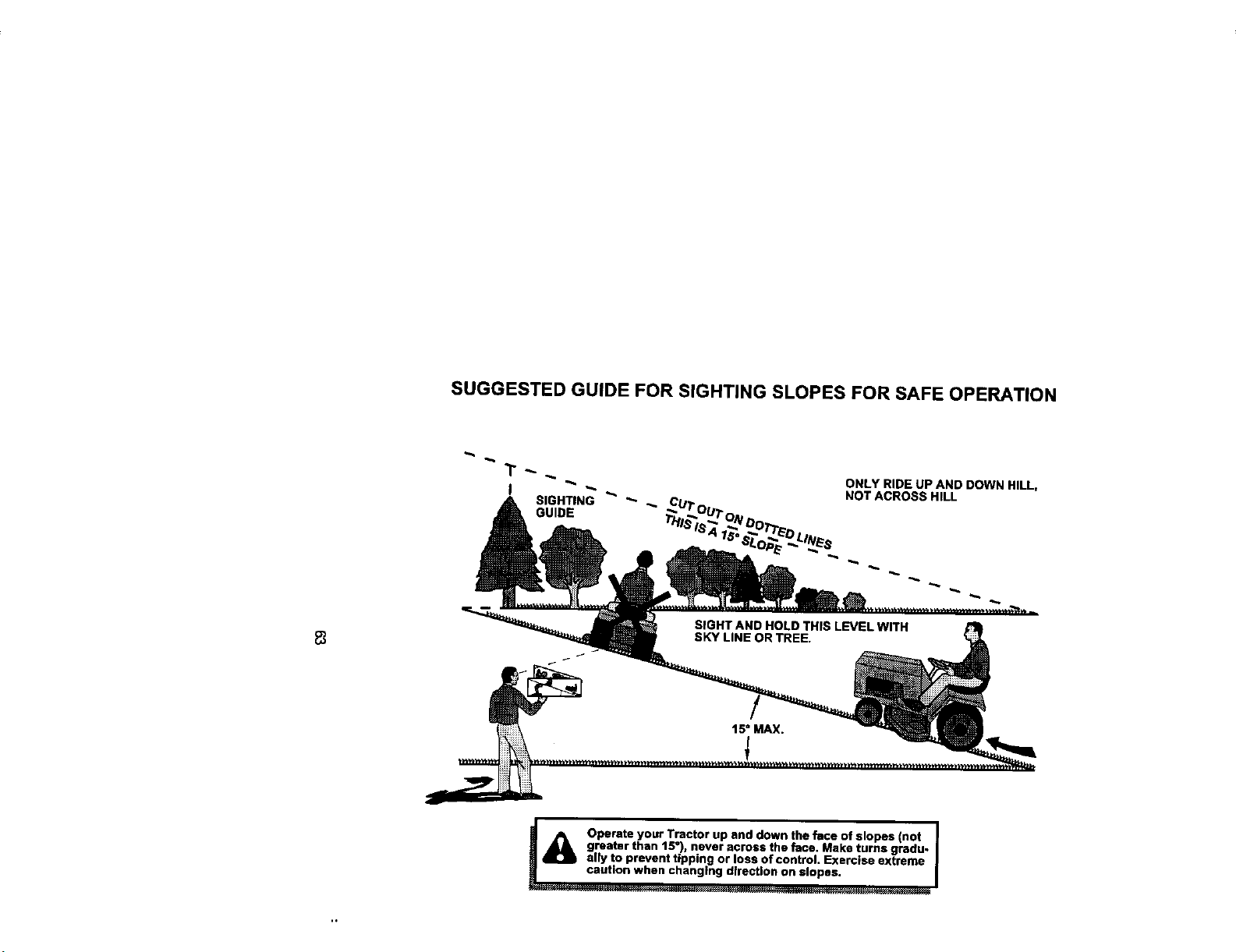
SUGGESTED GUIDE FOR SIGHTING SLOPES FOR SAFE OPERATION
ONLY RIDE UP AND DOWN HILL,
NOT ACROSS HILL
8
!_ Operate your Tractor up and down the face of slopes (not I
greater than 15°) never across the face. Make turns gradu-
ally to prevent tipping or loss of control. Exerc se extreme
caution when changing direction on slopes.
I ......... _._ _: .... ....,...,..,,,_.,.,........,,,..,_ _._._
Forrepairofmajorbrandappliancesinyourown home...
nomatterwhomadeit,nomatterwhosold
Forrepairofcarry-inproductslikevacuums,lawnequipment,and
electronics,callforthenearestSears Padsand RepairCenter.
www.sear_com
For1hereplacementparts,accessoriesand owner'smanuals
_at you needto do-it-yourseff,callSearsPadsDirectS"!
1-800-366-PART 6a_m.- 11p.m., 7daysaweek
(1-8oo-368-7278) (u.s_ on_,)
www.seascor_0atsdiract
To purchaseor inquireabouta SearsServiceAgreement
orSearsMaJnteeanoeAgreement:
1-800-827-6655 (u.s._.) 1-800-361-6665 (Canada)
7a.m.- 5 p.m.,CST, M_n.- SaL 9 a.m.- 8p.m EST, M- F,4p.m.Sat.
parapedrse_iciodereparac_a
dorn_Jo,yparaofdenarp_eza_
1-888.SU-HOGAR_
(1-_8-7S_7)
AuCanadap_rse.aceenfrar_:
1.800-LE4=OYlERuc
WWW.SP.ai's.ca
@Registered Trademark / w_Trademark / sMService Mark of Sears, Roebuck and Co.
® Marca Reglstrada / TMMarca de Fabrica / sMMa_'cade Servicio de Seam, Rcebuck and Co,
MCMarque de commerce / MeMarque ddpos6e de Sears, Roebuck and CO.
178495 2.20.01 JH Pdntedin U.S.A.


