
1
Owner’s Manual
SmartRack
®
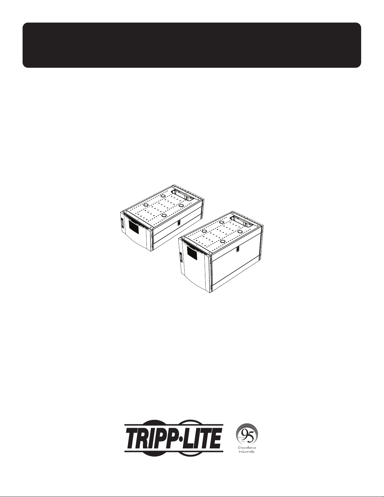
Vertical Expansion Rack
Models: SRTH6UB, SRTH12UB
(Series Numbers: AG-0545, AG-0546)
1111 W. 35th Street, Chicago, IL 60609 USA • tripplite.com/support
Copyright © 2021 Tripp Lite. All rights reserved.
WARRANTY REGISTRATION
Register your product today and be
automatically entered to win an ISOBAR
®
surge protector in our monthly drawing!
tripplite.com/warranty
Español 16 • Français 31 • Русский 46

2
Important Safety Instructions 3
Compatible Rack Enclosures 4
Feature Identification 5
Configuration 6
Ground Connection 6
Adding or Removing Front and 6
Rear Doors
Removing Door 6
Reversing Front Door 7
Adding or Removing Roof Panel 9
Adding or Removing Side Panels 10
Adjusting Mounting Rails and 11
Cable Management Rails
Equipment Installation 12
Installing or Removing Cage Nuts 12
Specifications 13
Storage and Service 14
Warranty and 15
Product Registration
Table of Contents

3
Important Safety Instructions
SAVE THESE INSTRUCTIONS
All sections of this manual contain instructions and warnings that should be followed during the installation and
use of the Vertical Expansion Rack as described in this manual. Read all instructions and warnings thoroughly
before attempting to move, install or use the Vertical Expansion Rack as described in this manual. Failure to
comply will create a risk of personal injury and property damage and may invalidate the warranty.
• Keep the enclosure in a controlled indoor environment, away from moisture, temperature extremes, flammable liquids and
gasses, conductive contaminants, dust and direct sunlight.
• Leave adequate space at the front and rear of the enclosure for proper ventilation. Do not block, cover or insert objects into
the external ventilation openings of the enclosure.
• The enclosure is extremely heavy. Use caution when handling the enclosure. Do not attempt to unpack, move or install it
unassisted. Use a mechanical device such as a forklift or pallet jack to move the enclosure in the shipping container.
• Do not place any object on the enclosure, especially containers of liquid, and do not attempt to stack the enclosures or
more than one height adjustment kit on top of the enclosure.
• Inspect the Vertical Expansion Rack’s contents for shipping damage. Do not use the Vertical Expansion Rack if it is
damaged.
• Leave the enclosure in the shipping container until it has been moved as close to the final installation location as possible.
• The Vertical Expansion Rack is intended to be installed on top of Tripp Lite SmartRack Rack Enclosure models that are
secured to the building structure for stability.
• This equipment is intended to be installed by skilled, qualified service personnel.
• Install the SmartRack Rack Enclosure and Vertical Expansion Rack in a structurally sound area with a level floor that is able
to bear the weight of the enclosure and all equipment that will be installed and/or equipment that will be installed nearby.
• Be sure to connect the enclosure to ground. See Ground Connection for more information.
• Use caution when cutting packing materials. The contents could be scratched, causing damage not covered by the warranty.
• Save all packing materials for later use. Repacking and shipping the enclosure without the original packing materials may
cause product damage that will void the warranty.
• Do not re-ship the enclosure with additional equipment unless the enclosure was shipped with a special shock pallet (“SP1”
models only). The combined weight of the enclosure and installed equipment must not exceed the load capacity of the
pallet. Tripp Lite is not responsible for any damage that occurs during re-shipment.
• Not for use when children are present.
• Use of this equipment in life support applications where failure of this equipment can reasonably be expected to cause the
failure of the life support equipment or to significantly affect its safety or effectiveness is not recommended.
CAUTION
GROUND
4
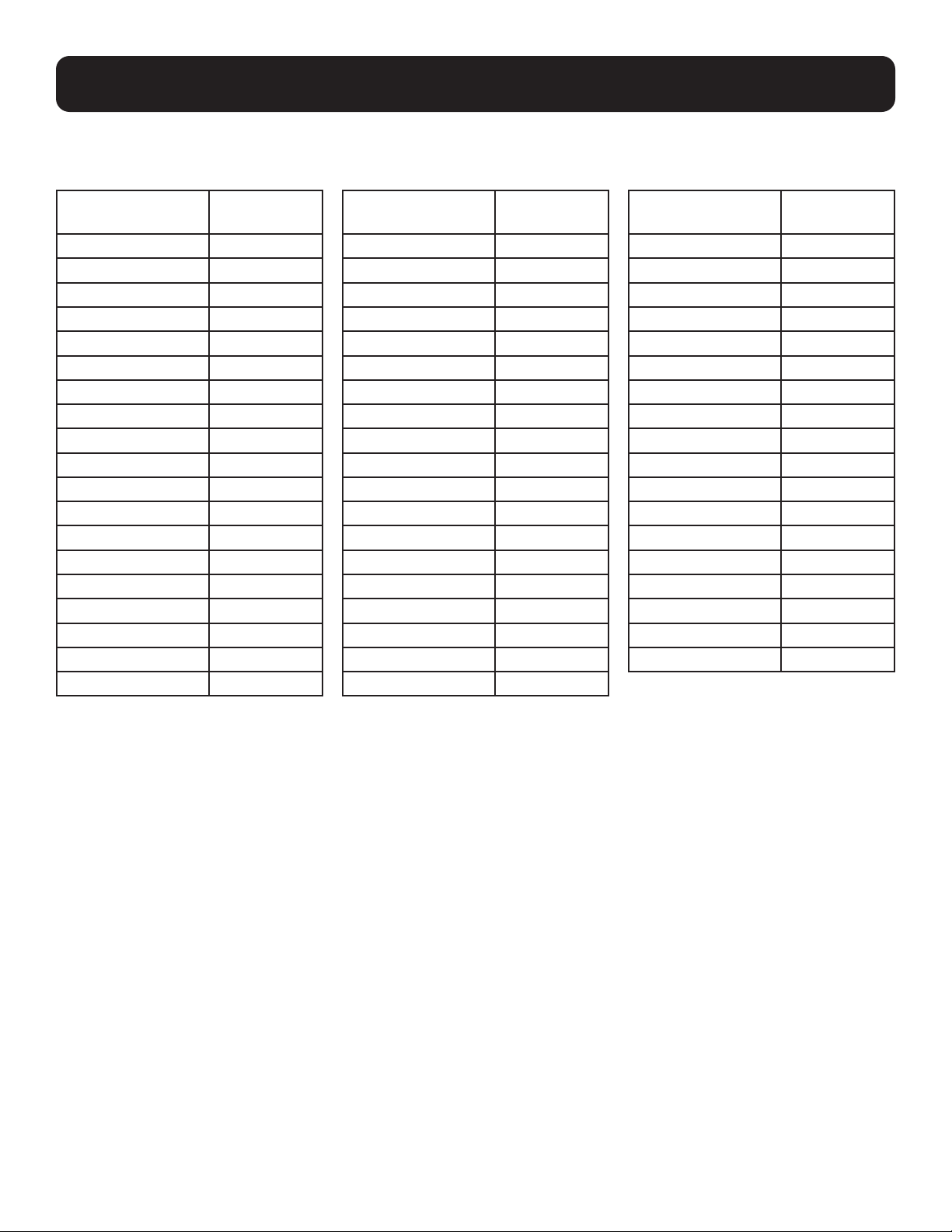
Compatible Rack Enclosures
The SRTH6UB and SRTH12UB Vertical Expansion Racks are compatible with the Tripp Lite SmartRack Rack Enclosure models
shown below, including Agency Series AGAC7006, AGAC7454, AGAC7761, AG-00BE, AG-0324, AG-0325, AG-0534,
AG-0535, AG-0536:
Model
SR2400
SR25UB
SR25UB
SR25UB3
SR25UB3001
SR25UBEXP
SR25UBSP1
SR25UBSP1
SR42UB
SR42UB
SR42UB
SR42UB007
SR42UB1032
SR42UB3
SR42UB3002
SR42UBC
SR42UBC001
SR42UBCL
SR42UBCLSP1
Model
SR42UBEXP
SR42UBEXP001
SR42UBEXP002
SR42UBEXP003
SR42UBEXP004
SR42UBEXP1032
SR42UBEXPC001
SR42UBEXPND
SR42UBEXPND3
SR42UBEXPNDNR3
SR42UBG
SR42UBG001
SR42UBG3
SR42UBG3001
SR42UBKD
SR42UBND
SR42UBSFDKD
SR42UBSP1
SR45UB
Model
SR45UBEXP
SR45UBEXPND
SR45UBEXPNDNR3
SR45UBND
SR45UBSP1
SR48UB
SR48UB3
SR48UB3
SR48UBCL
SR48UBEXP
SR48UBEXPND
SR48UBEXPNDNR
SR48UBEXPNDNR3
SR48UBSP1
SR50UB
SR52UB
SR55UB
SRX42UBAB
5
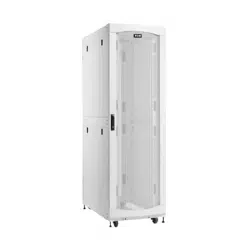
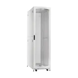
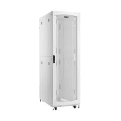
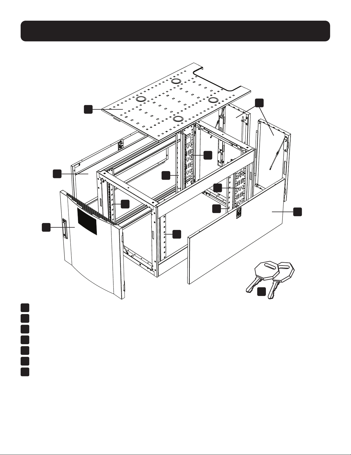
Feature Identification
Model SRTH12UB shown.
1
Roof Panel
2
Locking Split Rear Doors
3
Locking Side Panels
4
Cable Management Rails
5
Mounting Rails (Provide horizontal and vertical mounting points for equipment.)
6
Locking Reversible Front Door
7
Keys (One for the doors and one for the side panels.)
Not Shown: Mounting hardware, documentation, shipping brackets and other shipping materials.
1
3
6
3
2
4
4
5
5
5
5
7
6
Configuration
Before proceeding with configuration, make sure the unit is properly assembled and secured to the rack
enclosure. Refer to the Assembly Instructions document for step-by-step instructions.
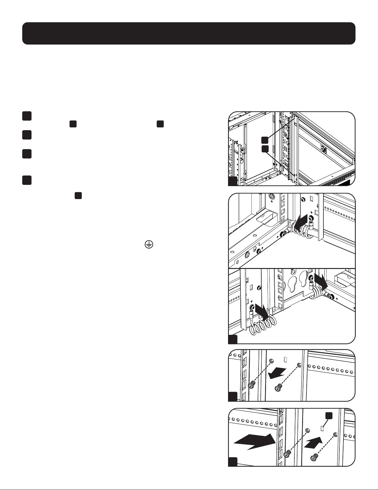
Ground Connection
The unit includes multiple threaded grounding points labeled
. To establish a ground, choose a grounding point and use the
included M6 screw to connect the frame of the unit directly to your facility’s earth ground connection with an 8 AWG
(3.264 mm) wire. Make sure to route the ground wire through the enclosure’s frame to ensure unhindered door operation.
WARNING: Attach each enclosure to earth ground separately. Do not use the enclosure without an earth ground
connection.
Adding or Removing Front and Rear Doors
WARNING: Do not attempt to add or remove doors without assistance.
90°
1
2
3
Removing Door
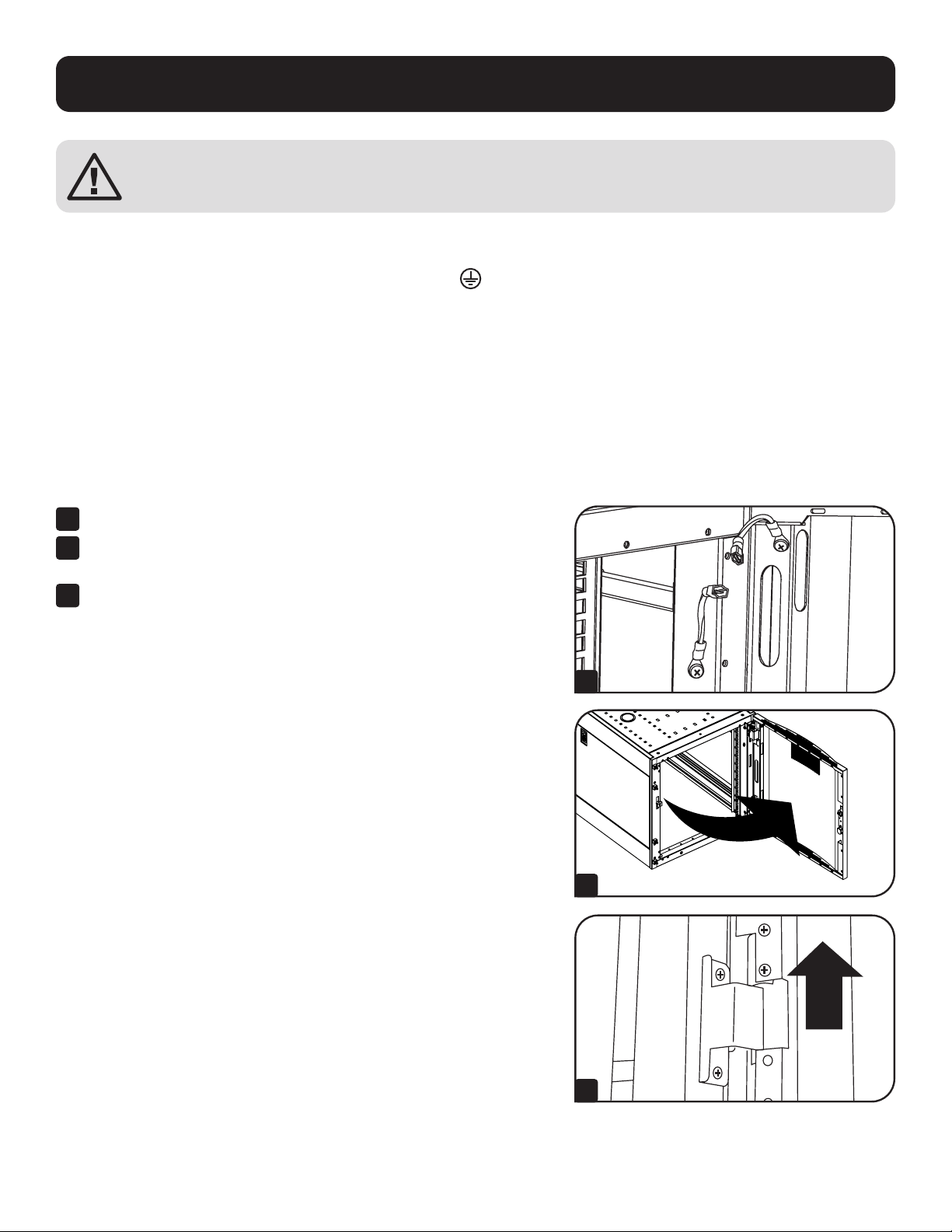
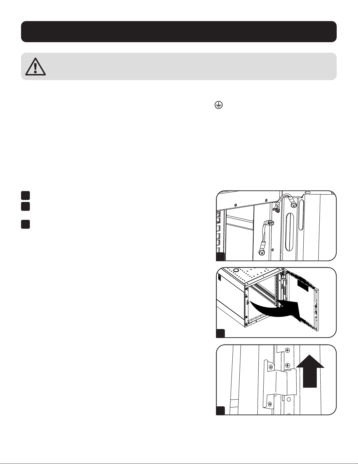
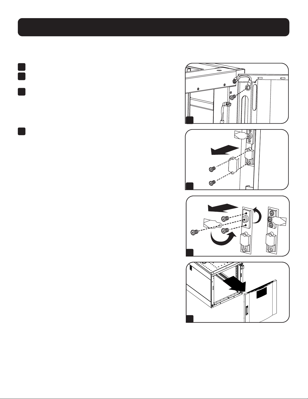
1
Disconnect the door’s ground wire.
2
Open the door until it is perpendicular (90 degrees) to the front
of the enclosure.
3
Lift the door from the hinges and remove it from the enclosure.
To Reinstall Door, Reverse Steps 1-3
7
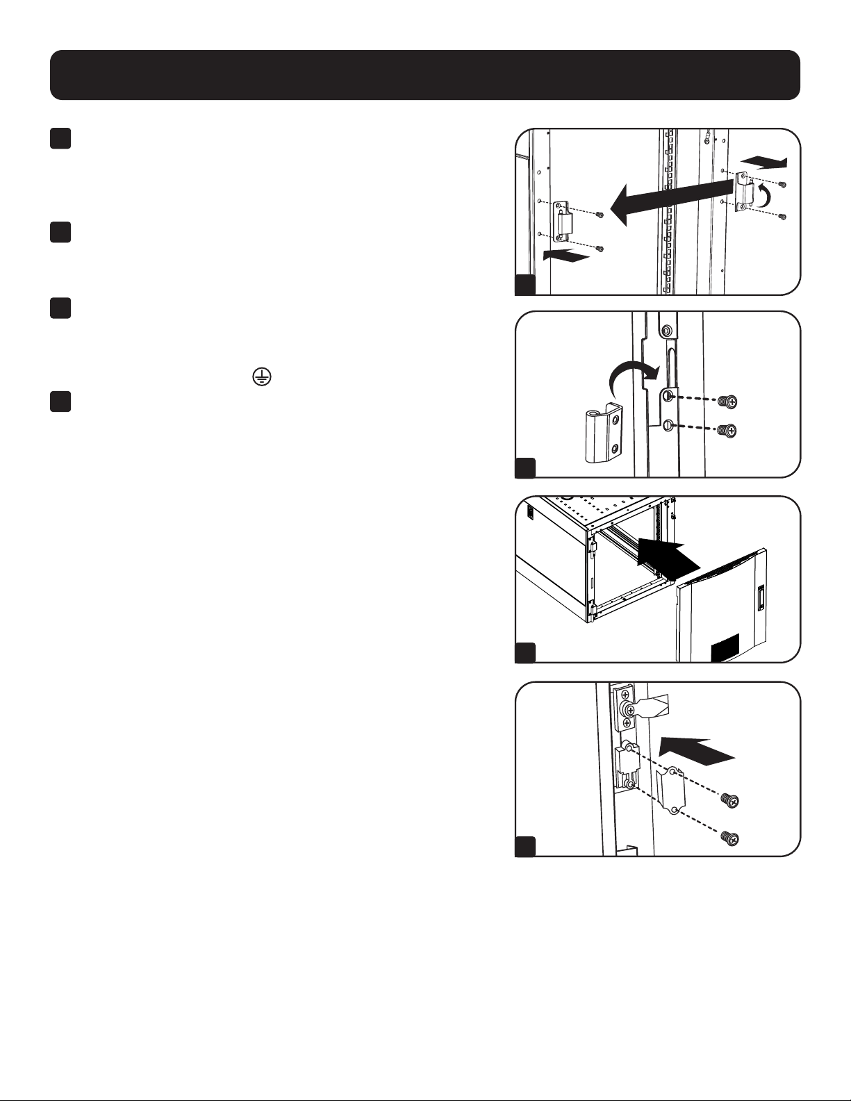
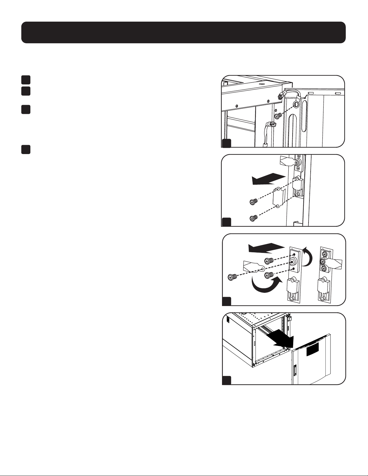
Reversing Front Door
WARNING: Do not attempt to reverse the front door without assistance.
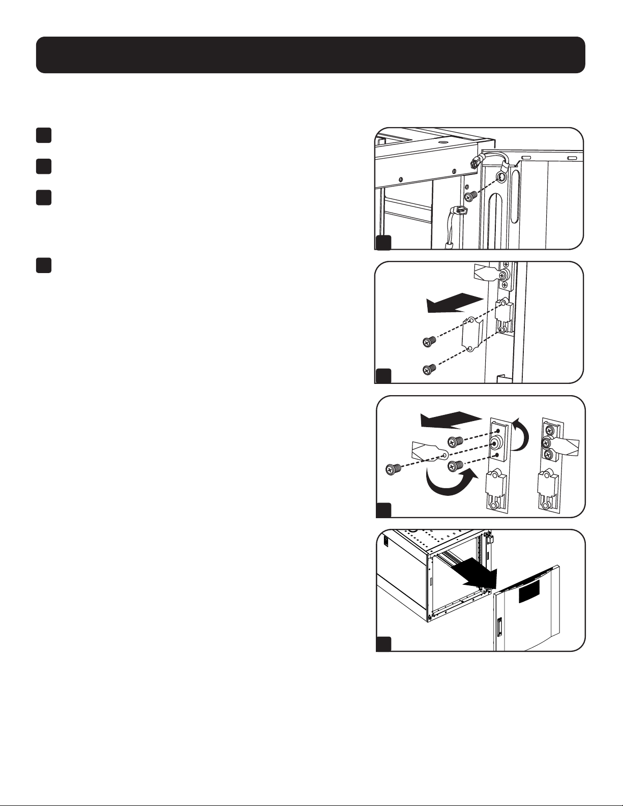
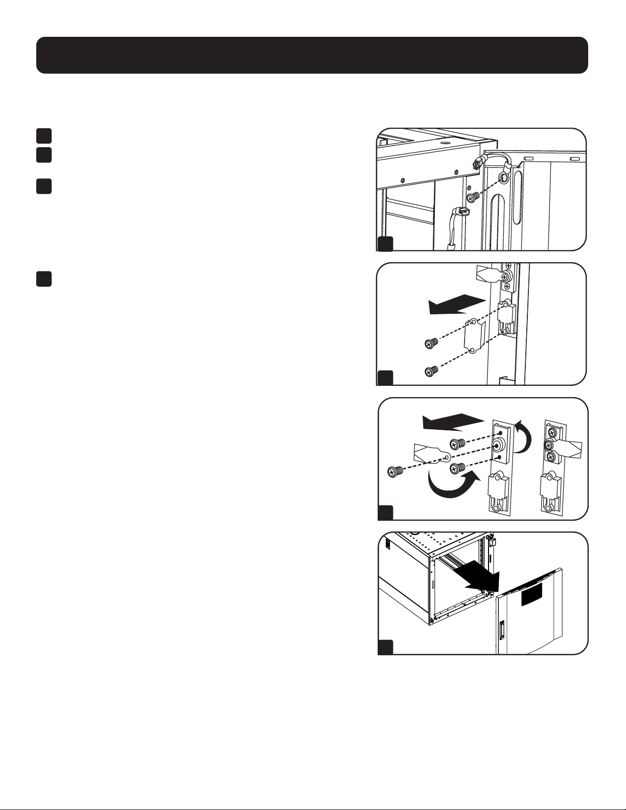
1
Remove the screw connecting the ground wire to the inside of the
door.
2
Remove the 2 screws connecting the door handle to the door.
Remove the door handle.
3
Remove the screw and washer from the rear of the door handle and
remove the latching mechanism. Rotate the latch washer counter-
clockwise 90 degrees and reverse the latch so it points in the
opposite direction, then use the screw and washer to re-attach the
latch to the rear of the door handle.
4
Remove the door by following the steps in the previous section.
1
2
3
4
Configuration
8
Configuration
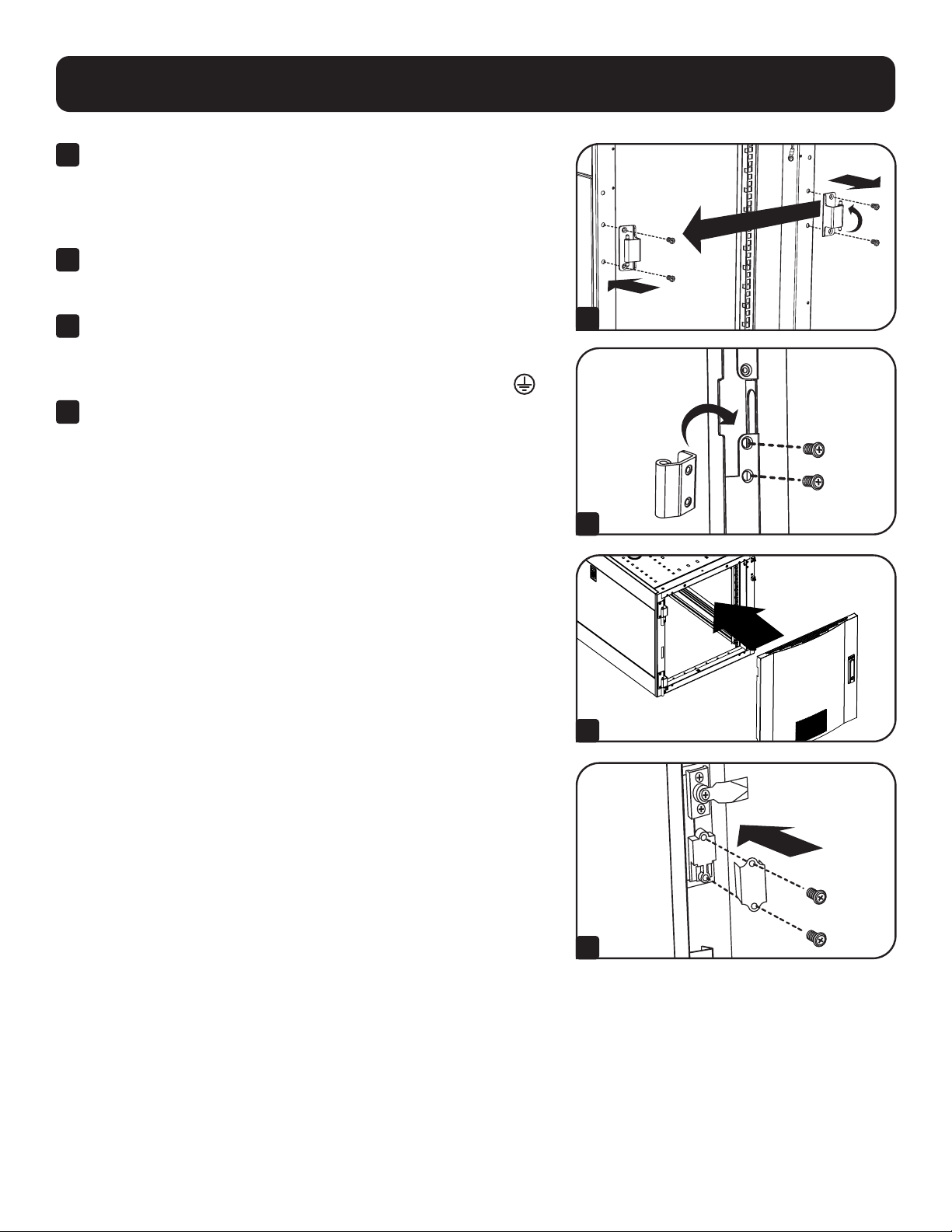
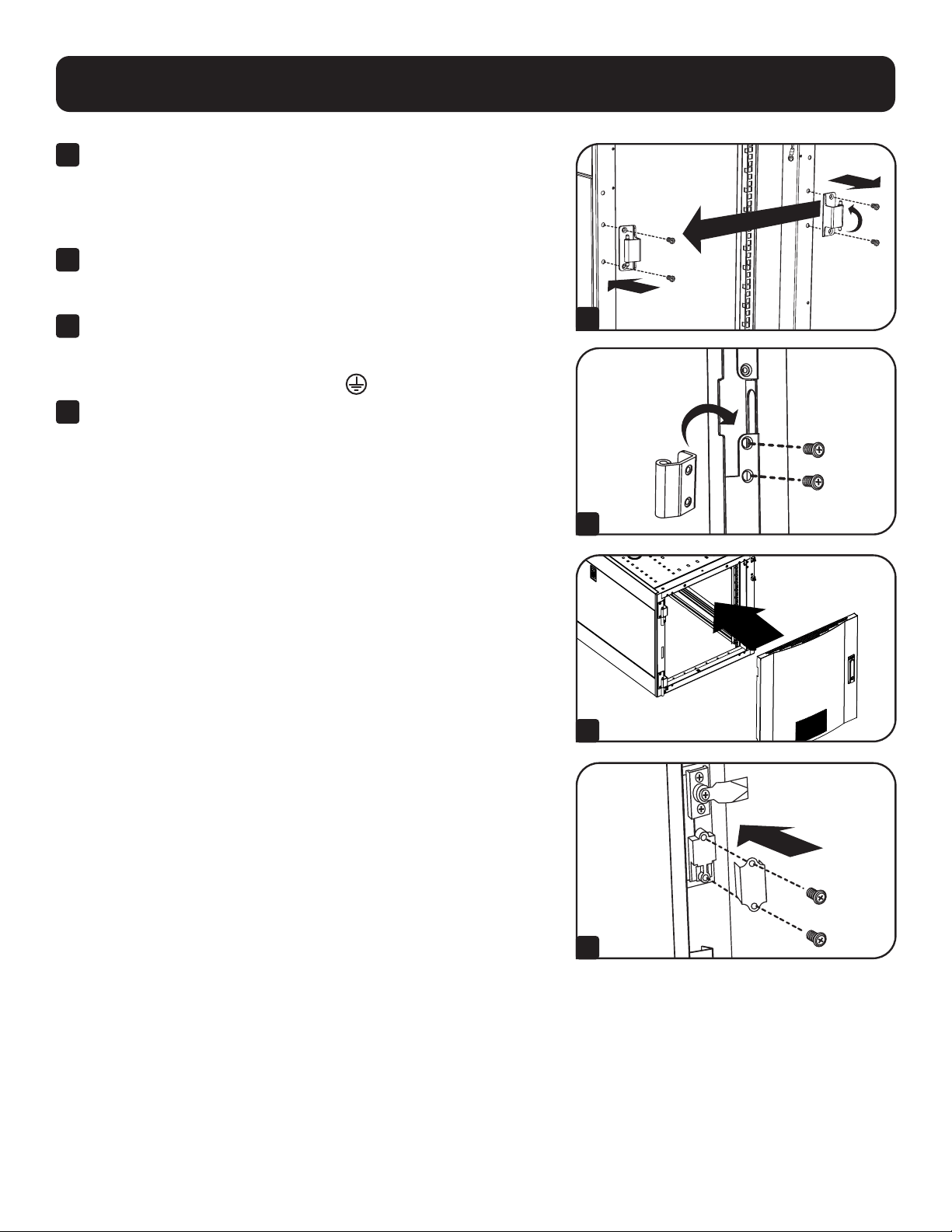
5
Remove the door hinges from the enclosure, rotate them
180 degrees and attach them on the opposite side of the enclosure.
Note: The alternate door hinge attachment points have plastic plugs in the
screw holes. Remove the plugs and insert them in the original door hinge
attachment points.
6
Unscrew the 2 hinge mechanisms from the hinge openings inside
the door, then reattach each of them using the set of screw holes
immediately opposite their original position.
7
Rotate the door 180 degrees and reinstall it on the enclosure.
Remember to connect the ground wire to the inside of the door, using
the attachment point nearest the hinge at the top of the door. The
attachment point is marked with the ground connection symbol
.
8
Reinstall the door handle.
5
6
7
8
9
Configuration
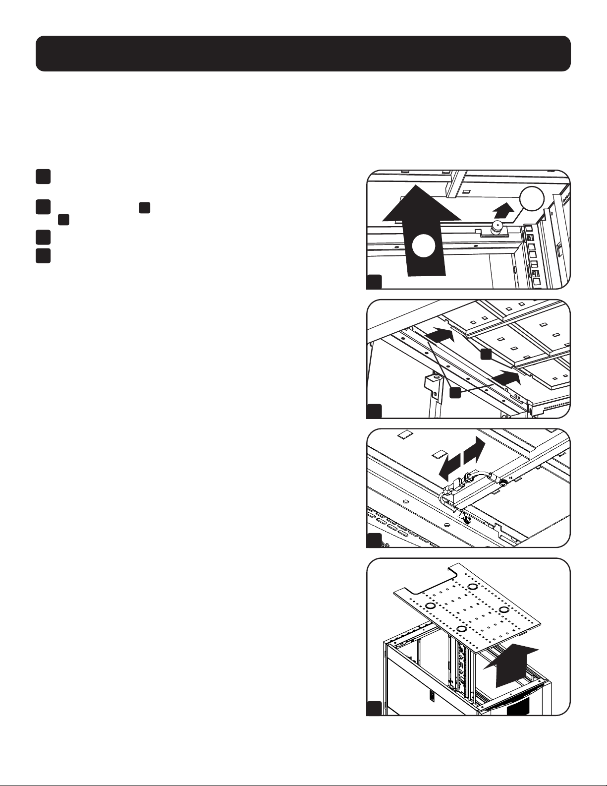
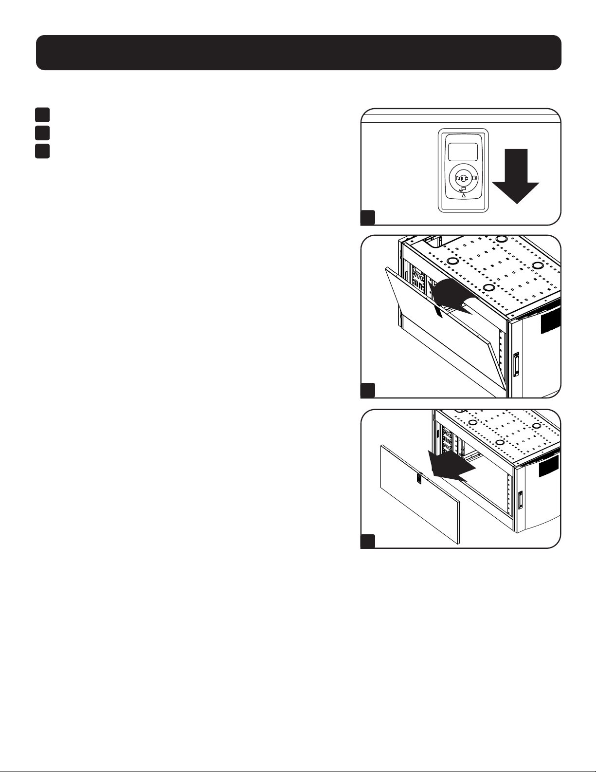
Adding or Removing Roof Panel
WARNING: Do not attempt to use the roof panel for weight-bearing purposes other than those explicitly described
and approved by Tripp Lite. Do not attempt to add or remove the roof panel without assistance.
Removing Roof Panel
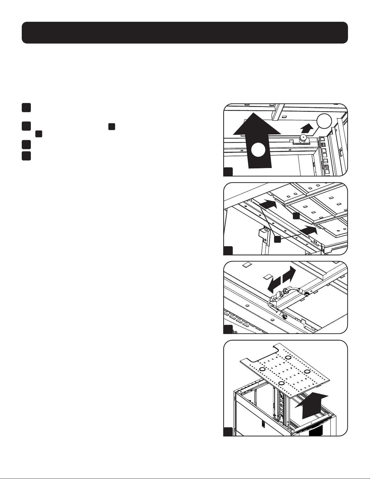
1
Pull the 2 pins near the rear of the roof panel. While holding the pins,
push the roof panel upward.
2
Remove the roof panel tabs
A
from the roof panel attachment slots
B
in the enclosure frame.
3
Disconnect the ground wire located on the side panel.
4
Lift the roof panel from the enclosure.
To Reinstall Roof Panel, Reverse Steps 1-4
2
1
A
B
1
2
3
4

10
Configuration
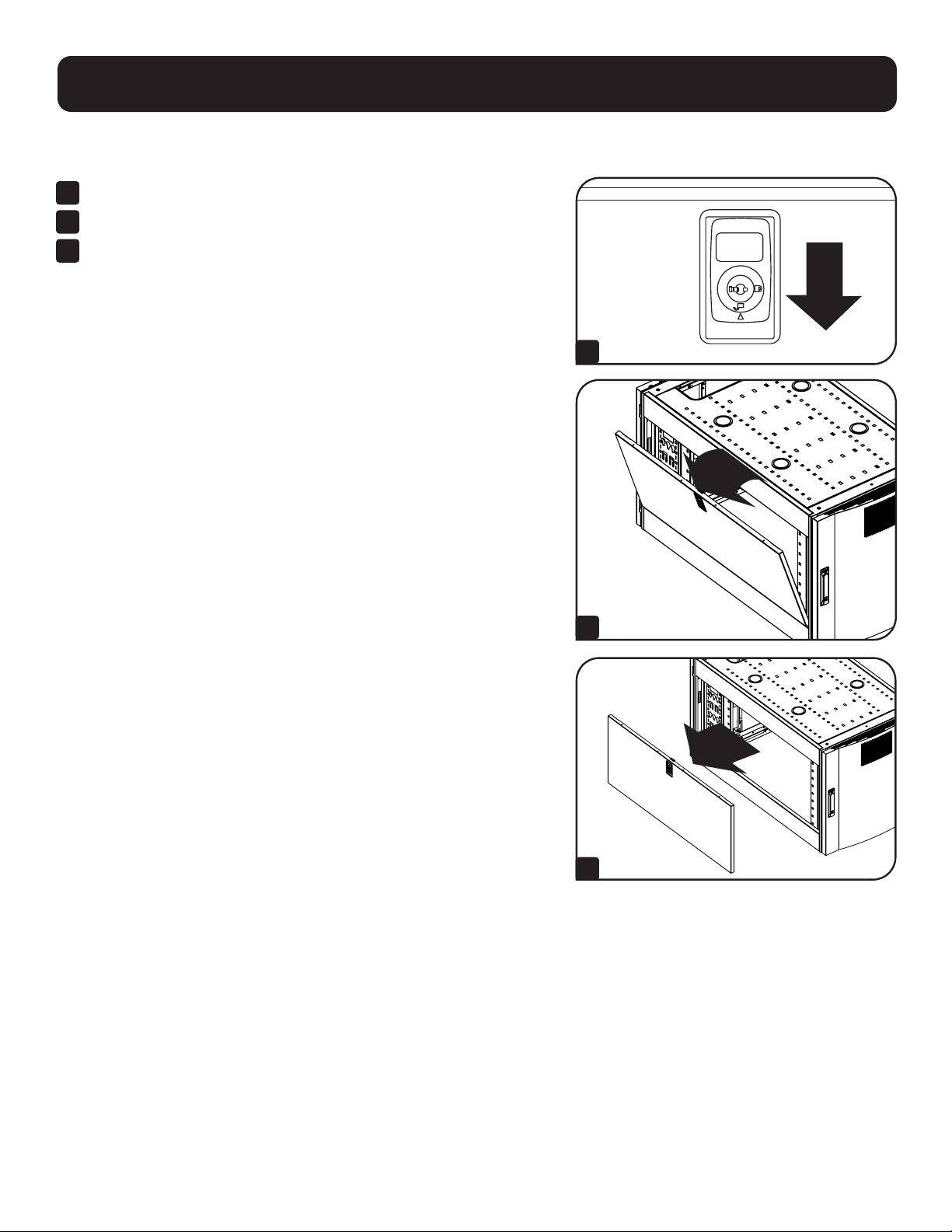
Adding or Removing Side Panels
1
Open the latch by sliding it downward.
2
Tilt the top of the panel away from the enclosure.
3
Lift the panel away from the brace that supports it.
To Reinstall Side Panel, Reverse Steps 1-3
1
2
3
11
Configuration
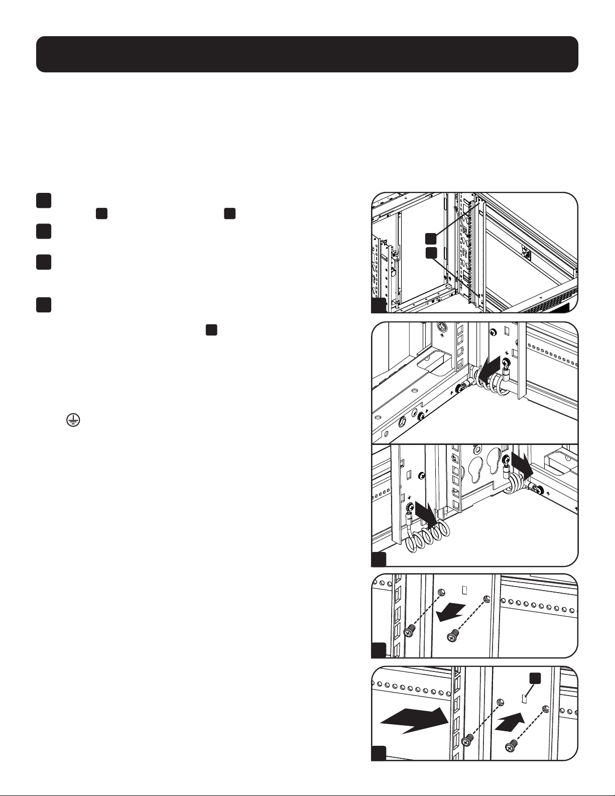
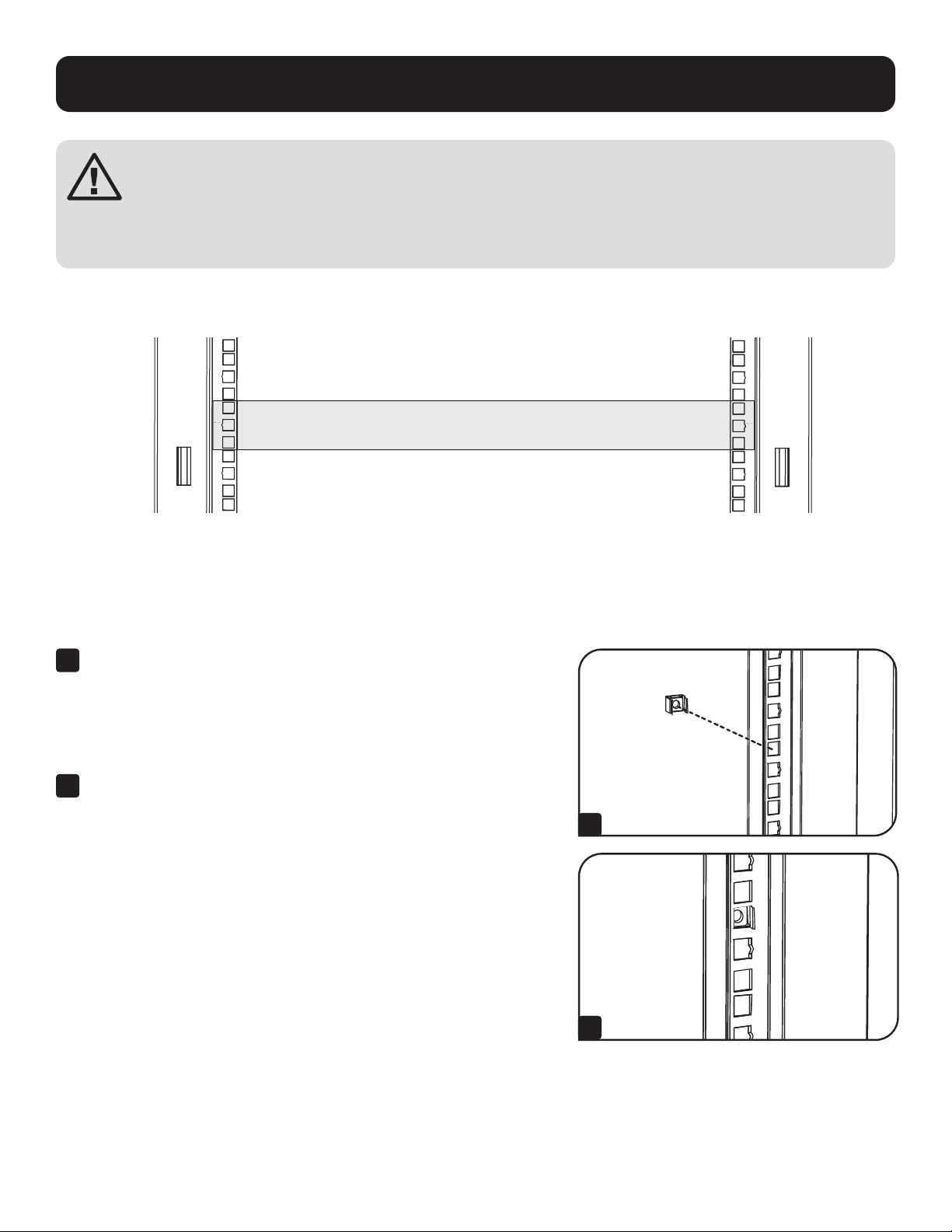
Adjusting Mounting Rails and Cable Management Rails
WARNING: Do not attempt to adjust rails without assistance. Do not attempt to adjust rails while equipment is
installed in the unit. Do not attempt to use rails without screws installed (4 per rail).
The 4 mounting rails accommodate equipment with a mounting depth of 30 inches (762 mm). Do not adjust the mounting
rails unless your equipment requires a different mounting depth. The front and rear sets of rails can be adjusted independently
in ¼-inch (6 mm) increments for mounting depths between 4 inches (101.6 mm) and 42 inches (1066.8 mm).
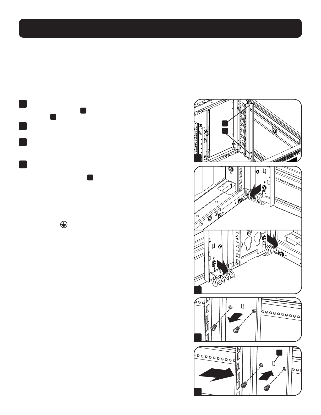
1
Each rail is connected to the enclosure with 4 screws - 1 pair at the
upper beam
A
and 1 pair at the lower beam
B
.
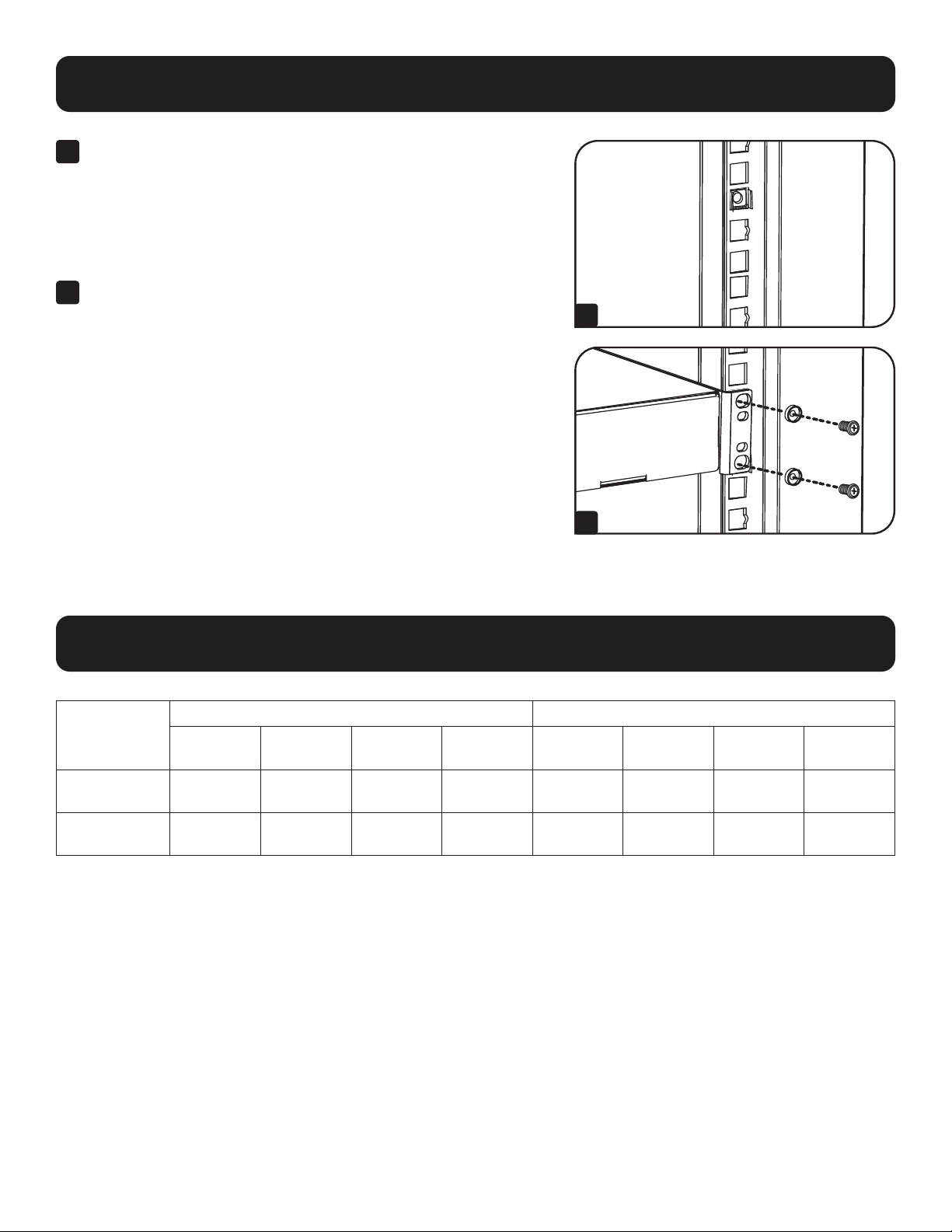
2
Remove the screws connecting the ground wire to the equipment
mounting rail.
3
Remove the screws fastening each of the rear mounting rails to the
enclosure. (If adjustment of the front rails is required, you can also
remove the screws from the front rails.)
4
Slide the mounting rails to the desired depth and reattach them
using the screws you removed in Step 2. The rail attachment points
are numbered
A
to help you align each pair of rails at the same
depth.
The depth of the cable management rails can be adjusted using the same
method.
Note: Remember to reconnect the ground wires to the equipment mounting rails
using the attachment point located near the bottom of the unit. The attachment
point is marked with the ground connection symbol
.
4 5 6 3 4 5 6 7 8 9 0 1 2
8
6 7 8 9 0 1 2 3 4 5
6 0 1 2
5
A
B
A
1
3
2
4
12
Equipment Installation
WARNING: Do not install equipment until you have assembled and secured the unit in accordance with
the Assembly Instructions. Install heavier equipment first and toward the bottom of the enclosure.
Install equipment starting from the bottom of the enclosure and proceeding toward the top of the
enclosure - never the reverse. If using sliding equipment rails, be careful when extending the rails. Do
not extend more than one set of sliding equipment rails at one time. Avoid extending sliding equipment
rails near the top of the enclosure.
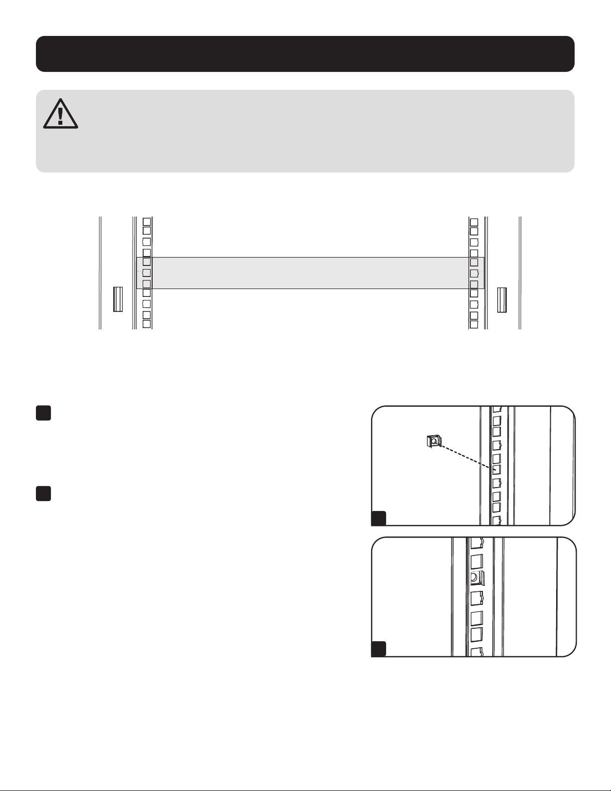
Note: The square holes at the middle of each rack unit are numbered and also include a small notch to aid identification. A single rack unit
includes the space occupied by the numbered hole and the holes directly above and below.
24
25
23
24
25
23
24
24
2
1 Rack Unit
1 Rack Unit
Installing or Removing Cage Nuts
WARNING: The flanges of the cage nuts should engage the sides of the square opening in the rail, not the top and
bottom. Follow the instructions in your equipment documentation to ensure proper installation of your equipment.
20
19
22
21
20
19
21
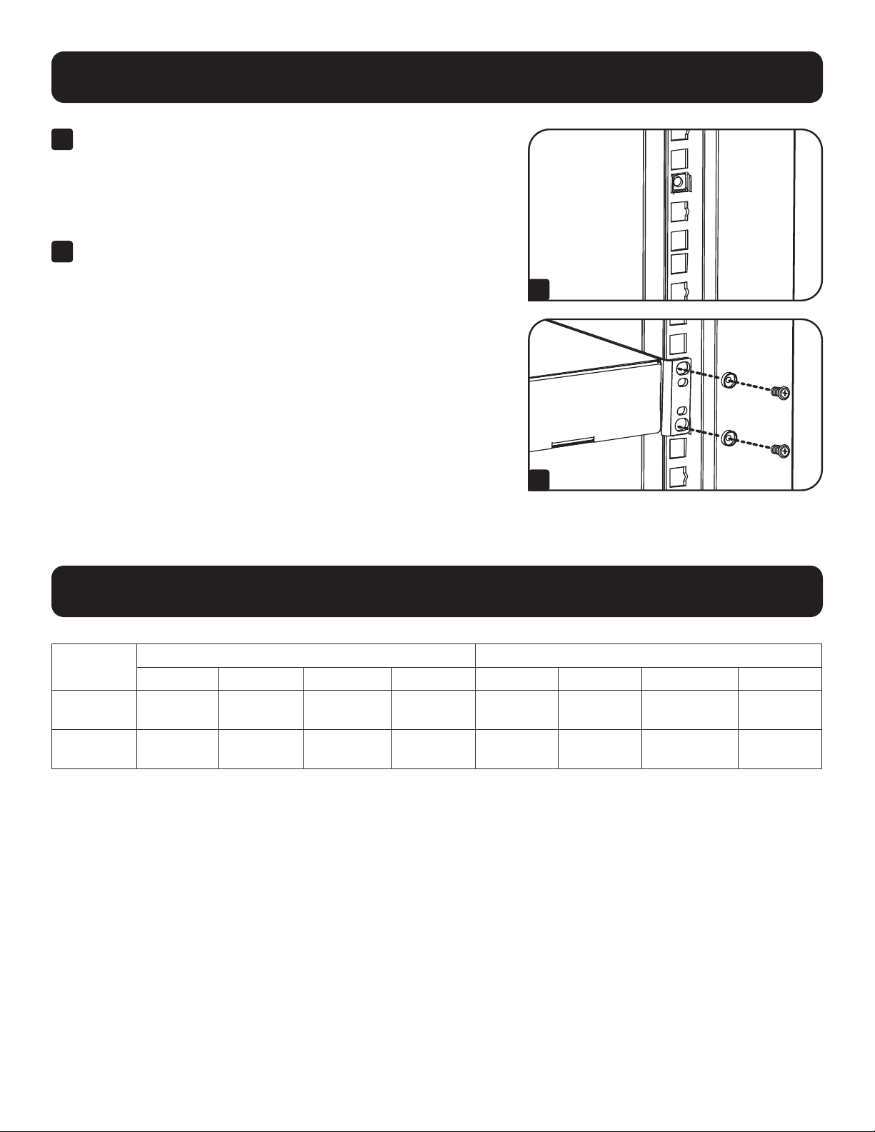
1
Locate the numbered square openings in the mounting rails
where you plan to install your equipment. You will install cage nuts
(included) into the square openings in order to provide an attachment
point for the mounting screws (included).
Note: Consult your equipment documentation to determine how many cage
nuts will be required and where they will need to be installed.
2
From the inside of the mounting rail, insert one of the flanges of the
cage nut through the square opening. Press it against the side of the
square opening. Each flange should engage one side of the square
opening, not the top or bottom.
1
2

13
Equipment Installation
Specifications
3
Compress the cage nut at the sides slightly to allow the remaining
flange to fit through the square opening. When the cage nut is
properly installed, both flanges will protrude through the square
opening and will be visible on the outer surface of the mounting rail.
Repeat steps 1-3 until all required cage nuts are installed.
4
After installing the required cage nuts, use the included mounting
screws and cup washers to secure your equipment to the rack rail.
Place the cup washers between the screws and the equipment
mounting brackets.
Note: Your equipment may also include mounting hardware. Read the
mounting instructions that came with your equipment before installing your
equipment.
To Remove Cage Nuts, Reverse Steps 1-3
Note: You may wish to use a cage nut tool (user-supplied) to aid cage nut
installation and removal.
20
19
21
20
19
21
3
4
Model
Unit Dimensions Shipping Dimensions
Height Width Depth Weight Height Width Depth Weight
SRTH6UB
13.3”
(338 mm)
23.6"
(599 mm)
43"
(1092 mm)
84.8 lb.
(38.5 kg)
22.8"
(579 mm)
39.2"
(996 mm)
10.6"
(269 mm)
100 lb.
(45.4 kg)
SRTH12UB
23.9"
(607 mm)
23.6"
(599 mm)
43"
(1092 mm)
118 lb.
(53.5 kg)
24.4"
(620 mm)
39.2"
(996 mm)
15.4"
(391 mm)
132 lb.
(60 kg)

14
Storage and Service
Storage
The enclosure should be stored in a controlled indoor environment, away from moisture, temperature extremes, flammable
liquids and gasses, conductive contaminants, dust and direct sunlight. Store the enclosure in its original shipping container if
possible.
Service
Your Tripp Lite product is covered by the warranty described in this manual. A variety of Extended Warranty and On-Site Service
Programs are also available from Tripp Lite. For more information on service, visit tripplite.com/support. Before returning your
product for service, follow these steps:
1. Review the installation and operation procedures in this manual to insure that the service problem does not originate from
a misreading of the instructions.
2. If the problem continues, do not contact or return the product to the dealer. Instead, visit tripplite.com/support.
3. If the problem requires service, visit tripplite.com/support and click the Product Returns link. From here you can request
a Returned Material Authorization (RMA) number, which is required for service. This simple on-line form will ask for your
unit’s model and serial numbers, along with other general purchaser information. The RMA number, along with shipping
instructions will be emailed to you. Any damages (direct, indirect, special or consequential) to the product incurred during
shipment to Tripp Lite or an authorized Tripp Lite service center is not covered under warranty. Products shipped to Tripp Lite
or an authorized Tripp Lite service center must have transportation charges prepaid. Mark the RMA number on the outside
of the package. If the product is within its warranty period, enclose a copy of your sales receipt. Return the product for
service using an insured carrier to the address given to you when you request the RMA.

15
Warranty and Product Registration
5-Year Limited Warranty
Seller warrants this product, if used in accordance with all applicable instructions, to be free from original defects in material and workmanship for a period of
5 years from the date of initial purchase. If the product should prove defective in material or workmanship within that period, Seller will repair or replace the
product, in its sole discretion.
THIS WARRANTY DOES NOT APPLY TO NORMAL WEAR OR TO DAMAGE RESULTING FROM ACCIDENT, MISUSE, ABUSE OR NEGLECT. SELLER MAKES NO
EXPRESS WARRANTIES OTHER THAN THE WARRANTY EXPRESSLY SET FORTH HEREIN. EXCEPT TO THE EXTENT PROHIBITED BY APPLICABLE LAW, ALL IMPLIED
WARRANTIES, INCLUDING ALL WARRANTIES OF MERCHANTABILITY OR FITNESS, ARE LIMITED IN DURATION TO THE WARRANTY PERIOD SET FORTH ABOVE;
AND THIS WARRANTY EXPRESSLY EXCLUDES ALL INCIDENTAL AND CONSEQUENTIAL DAMAGES. (Some states do not allow limitations on how long an implied
warranty lasts, and some states do not allow the exclusion or limitation of incidental or consequential damages, so the above limitations or exclusions may not
apply to you. This warranty gives you specific legal rights, and you may have other rights which vary from jurisdiction to jurisdiction).
WARNING: The individual user should take care to determine prior to use whether this device is suitable, adequate or safe for the use intended. Since
individual applications are subject to great variation, the manufacturer makes no representation or warranty as to the suitability or fitness of these devices for
any specific application.
Product Registration
Visit tripplite.com/warranty today to register your new Tripp Lite product. You’ll be automatically entered into a drawing for a chance to win a FREE Tripp Lite
product!*
* No purchase necessary. Void where prohibited. Some restrictions apply. See Web site for details.
Tripp Lite follows a policy of continuous improvement. Product specifications are subject to change without notice. Photos and illustrations may differ slightly
from actual products.
Note on Labeling
This symbol is used on the product:
Ground Connection
1111 W. 35th Street, Chicago, IL 60609 USA • tripplite.com/support
20-09-242 93-3D32_RevB

16
Manual del Propietario
Rack de Expansión Vertical
SmartRack
®
Modelos: SRTH6UB, SRTH12UB
(Números de Serie: AG-0545, AG-0546)
Para uso con Modelos SmartRack:
AGAC7006, AGAC7454, AGAC7761, AG-00BE, AG-0324, AG-0325, AG-0534, AG-0535, AG-0536
1111 W. 35th Street, Chicago, IL 60609, EE UU • tripplite.com/support
Copyright © 2021 Tripp Lite. Todos los derechos reservados.
English 1 • Français 31 • Русский 46

17
Instrucciones de Seguridad 18
Importantes
Gabinetes de Rack Compatibles 19
Identificación de Características 20
Configuración 21
Conexión a Tierra 21
Colocación o Retiro de las Puertas 21
Delanteras y Traseras
Retiro de la Puerta 21
Inversión de la Puerta Delantera 22
Colocación o Retiro del Panel de Techo 24
Colocación o Retiro de los Paneles 25
Laterales
Ajuste de los Rieles de Instalación y 26
Rieles para el Manejo del Cableado
Instalación del Equipo 27
Instalación o Retiro de las Tuercas de
Fijación 27
Especificaciones 28
Almacenamiento y Servicio 29
Garantía 30
Índice

18
Instrucciones de Seguridad Importantes
CONSERVE ESTAS INSTRUCCIONES
Todas las secciones de este manual contienen instrucciones y advertencias que deben observarse durante
la instalación y uso del Rack de Expansión Vertical descrito. Lea cuidadosamente todas las instrucciones y
advertencias antes de intentar mover, instalar o utilizar el Rack de Expansión Vertical descrito en este manual. El
incumplimiento creará un riesgo de lesiones personales y daños a la propiedad y puede invalidar la garantía.
• Mantenga el gabinete en un entorno interior controlado lejos de humedad excesiva, temperaturas extremas, líquidos y gases
inflamables, contaminantes conductores, polvo o luz solar directa.
• Deje espacio suficiente en la parte delantera y trasera del gabinete para una ventilación adecuada. No bloquee, cubra ni
coloque objetos en las aberturas externas de ventilación del gabinete.
• El gabinete es extremadamente pesado. Tenga cuidado al manipular el gabinete. No intente desempacarlo, moverlo o instalarlo
sin ayuda. Utilice un dispositivo mecánico como un montacargas o gato para tarimas para mover el gabinete en el contenedor
de embarque.
• No coloque ningún objeto sobre el gabinete, especialmente recipientes con líquidos y no intente apilar los gabinetes o más de
un ajuste de altura en la parte superior del gabinete.
• Inspeccione el contenido del Rack de Expansión Vertical para detectar daños en el embarque. No use el Rack de Expansión
Vertical si está dañado.
• Deje el gabinete en el contenedor de embarque hasta que haya sido movido tan cerca a su ubicación final como sea posible.
• El Rack de Expansión Vertical está diseñado para instalarse en la parte superior de los modelos de Gabinete SmartRack de
Tripp Lite que estén asegurados a la estructura del edificio para estabilidad.
• Este equipo está diseñado para ser instalado por personal de servicio entrenado y calificado.
• Instale el Gabinete SmartRack y el Rack de Expansión Vertical en un área estructuralmente firme con un piso nivelado que
pueda soportar la carga del peso del gabinete, de todo el equipo que se instale en el gabinete y otros gabinetes y otros
equipos que se instalen cerca.
• Asegúrese de conectar el gabinete a tierra. Vea Conexión a Tierra para obtener más información.
• Tenga cuidado cuando corte el material de empaque. El contenido podría haber sido rasguñado o rayado, causando daños no
cubiertos por la garantía.
• Guarde todo el material de empaque para uso posterior. Volver a empacar y enviar el gabinete sin el material de empaque
original puede ocasionar daños al producto que anularían la garantía.
• No reembarque el gabinete con equipo adicional a menos que el gabinete haya sido embarcado con una tarima especial anti-
impacto (solo modelos “SP1”). El peso combinado del gabinete y el equipo instalado no debe exceder la capacidad de carga
de la tarima. Tripp Lite no es responsable por cualquier daño que se produzca durante el reenvío.
• No se puede usar cuando hay niños presentes.
• No se recomienda el uso de este equipo en aplicaciones de soporte de vida en donde razonablemente se pueda esperar que
la falla de este equipo cause la falla del equipo de soporte de vida o afectar significativamente su seguridad o efectividad.
PRECAUCIÓN
CONEXIÓN A TIERRA

19
Gabinetes de Rack Compatibles
Los Racks de Expansión Vertical SRTH6UB y SRTH12UB son compatibles con los siguientes modelos de Gabinete SmartRack
de Tripp Lite:
Modelo Número de
parte
SR2400 AC8A08
SR25UB AC8480
SR25UB SR1090
SR25UB3 AC883F
SR25UB3001 SP87C0
SR25UBEXP SR1045
SR25UBSP1 AC7022
SR25UBSP1 SR1091
SR42UB AC89A3
SR42UB SP87BA
SR42UB SR1000
SR42UB007 AC8A52
SR42UB1032 SR1007
SR42UB3 SR1041
SR42UB3002 SP87BF
SR42UBC SR1089
SR42UBC001 AC881E
SR42UBCL SR1044
SR42UBCLSP1 AC89CF
Modelo Número de
parte
SR42UBEXP SR1002
SR42UBEXP001 SP87AA
SR42UBEXP002 SP87AB
SR42UBEXP003 SP87BE
SR42UBEXP004 SR107F
SR42UBEXP1032 SR8797
SR42UBEXPC001 AC881F
SR42UBEXPND SR1003
SR42UBEXPND3 SR1042
SR42UBEXPNDNR3 SR1004
SR42UBG SR1001
SR42UBG001 AC883E
SR42UBG3 SR107C
SR42UBG3001 AC8B66
SR42UBKD AC7174
SR42UBND AC8818
SR42UBSFDKD AC8AD9
SR42UBSP1 SR1005
SR45UB SR1014
Modelo Número de
parte
SR45UBEXP SR1019
SR45UBEXPND SR1020
SR45UBEXPNDNR3 SR1021
SR45UBND SR1015
SR45UBSP1 SR1022
SR48UB SR1052
SR48UB3 SR1064
SR48UB3 SR879A
SR48UBCL SR1053
SR48UBEXP SR1057
SR48UBEXPND SR1058
SR48UBEXPNDNR AC8841
SR48UBEXPNDNR3 SR1049
SR48UBSP1 SR1059
SR50UB AC003E
SR52UB AC003B
SR55UB AC003D
SRX42UBAB AC0024

20
Identificación de Características
Se muestra el modelo SRTH12UB.
1
Panel de Techo
2
Puertas Posteriores Divididas con Cerradura
3
Paneles Laterales con Cerradura
4
Rieles para el Manejo del Cableado
5
Rieles de Instalación (Proporcionan puntos de instalación horizontal y vertical para los equipos.)
6
Puerta Frontal Reversible con Cerradura
7
Llaves (Una para las puertas y una para los paneles laterales).
No se Muestra: Accesorios de instalación, documentación, soportes de embarque y otros materiales de embarque.
1
3
6
3
2
4
4
5
5
5
5
7
21
Configuración
Antes de continuar con la configuración, asegúrese de que la unidad esté correctamente ensamblada
y asegurada al gabinete. Consulte el documento de Instrucciones de Ensamble para obtener
instrucciones paso a paso.
Conexión a Tierra
La unidad incluye múltiples puntos roscados de conexión a tierra etiquetados
. Para establecer una conexión a tierra, elija
un punto de conexión a tierra y utilice el tornillo M6 incluido para conectar el marco de la unidad directamente a la conexión a
tierra de su instalación con un cable calibre 8 AWG (3.264 mm). Asegúrese de conducir el cable de tierra a través del marco
del gabinete para asegurar la operación sin obstáculos de la puerta.
ADVERTENCIA: Conecte a tierra cada gabinete por separado. No use el gabinete sin una conexión a tierra física.
Colocación o Retiro de las Puertas Delanteras y Traseras
ADVERTENCIA: No intente colocar o remover las puertas sin ayuda.
90°
1
2
3
Retiro de la Puerta
1
Desconecte el cable de conexión a tierra de la puerta.
2
Abra la puerta hasta que esté perpendicular (90 grados) con el frente
del gabinete.
3
Levante la puerta de las bisagras y retírela del gabinete.
Para Reinstalar la Puerta, Invierta los Pasos 1 a 3.
22
Inversión de la Puerta Delantera
ADVERTENCIA: No intente invertir la puerta frontal sin ayuda.
1
Quite el tornillo que conecta el cable a tierra al interior de la puerta.
2
Quite los 2 tornillos que conectan la manija de la puerta a la puerta.
Quite la manija de la puerta.
3
Retire el tornillo y arandela de la parte trasera de la manija de
la puerta y retire el mecanismo de enganche. Gire 90 grados
la arandela de la cerradura en sentido contrario a al giro de las
manecillas del reloj e invierta el mecanismo de enganche para que
apunte en la dirección opuesta, a continuación, utilice el tornillo y la
arandela para volver a colocar el mecanismo de enganche a la parte
posterior de la manija de la puerta.
4
Retire la puerta siguiendo los pasos de la sección anterior.
1
2
3
4
Configuración
23
Configuración
5
Quite las bisagras de la puerta, gírelas
180 grados y fíjelas del lado opuesto del gabinete.
Nota: Los puntos alternos para fijar las bisagras tienen pernos de plástico en
los orificios para los tornillos. Quítelos e insértelos en los puntos originales
de fijación de las bisagras.
6
Desatornille los 2 mecanismos de bisagra de las aberturas de la
bisagra dentro de la puerta y fije cada uno de ellos utilizando el
conjunto de orificios para tornillos directamente opuestos a su
posición original.
7
Rote la puerta 180 grados y vuelva a instalarla en el gabinete.
Recuerde conectar el cable de conexión a tierra al interior de la
puerta usando el punto de fijación más cercano a la bisagra en la
parte superior de la puerta. El punto de fijación está marcado con el
símbolo de conexión a tierra
.
8
Vuelva a instalar la manija de la puerta.
5
6
7
8
24
Configuración
Colocación o Retiro del Panel de Techo
ADVERTENCIA: No intente usar el panel de techo para soportar pesos que no sean los descritos explícitamente y
aprobados por Tripp Lite. No intente colocar o retirar el panel de techo sin ayuda.
Remoción del Panel de Techo
1
Jale las 2 clavijas cercanas a la parte trasera del panel de techo.
Mientras las sostiene, empuje el panel de techo hacia arriba.
2
Quite las pestañas
A
de las ranuras de fijación del panel de techo
B
en el marco del gabinete.
3
Desconecte el cable de tierra ubicado en el panel lateral.
4
Levante el panel de techo del gabinete.
Para volver a instalar el Panel de Techo, Invierta los Pasos 1 ~ 4.
2
1
A
B
1
2
3
4
25
Configuración
Colocación o Retiro de los Paneles Laterales
1
2
3
1
Abra el pestillo deslizándolo hacia abajo.
2
Incline la parte superior del panel hacia afuera del gabinete.
3
Levante el panel de la abrazadera que lo sostiene.
Para volver a instalar el Panel Lateral, invierta los pasos 1 a 3
26
Configuración
Ajuste de los Rieles de Instalación y Rieles para el Manejo del Cableado
ADVERTENCIA: No intente ajustar los rieles sin ayuda. No intente ajustar los rieles mientras el equipo está
instalado en la unidad. No intente usar los rieles sin los tornillos instalados (4 por riel).
Los 4 rieles de instalación acomodan equipos con una profundidad de instalación de 762 mm [30"]. No ajuste los rieles de
instalación a menos que su equipo requiera una profundidad de instalación diferente. Los juegos de rieles anterior y posterior
pueden ajustarse independientemente en incrementos de 6.35 mm [¼"] para instalación con profundidades entre 101.6 mm
[4"] y 1066.8 mm [42"].
1
Cada riel está fijado al gabinete con los 6 tornillos: un par en la viga
superior
A
y un par en la viga inferior
B
.
2
Retire los tornillos que conectan el cable de conexión a tierra al riel
de instalación del equipo.
3
Retire los tornillos que sujetan cada uno de los rieles al gabinete. (Si
se requiere el ajuste de los rieles delanteros, puede también quitar
los tornillos de los rieles delanteros).
4
Deslice los rieles de instalación a la profundidad deseada y vuélvalos
a instalar usando los tornillos que retiró en el Paso 2. Los puntos de
sujeción del riel están numerados
A
para ayudar a alinear cada par
de rieles a la misma profundidad.
La profundidad de los rieles de administración de cables se puede ajustar
utilizando el mismo método.
Nota: Recuerde reconectar los cables de conexión a tierra a los rieles de
instalación del equipo usando el punto de fijación ubicado cerca de la parte
inferior de la unidad. El punto de fijación está marcado con el símbolo de conexión
a tierra
.
4 5 6 3 4 5 6 7 8 9 0 1 2
8
6 7 8 9 0 1 2 3 4 5
6 0 1 2
5
A
B
A
1
3
2
4
27
Instalación del Equipo
ADVERTENCIA: No instale el equipo hasta que haya ensamblado y asegurado la unidad de acuerdo con
las instrucciones de ensamble. Instale primero los equipos más pesados y hacia la parte inferior del
gabinete. Instale los equipos a partir de la parte inferior del gabinete y proceda hacia la parte superior
del gabinete - nunca al revés. Si utiliza guías de equipos deslizantes, tenga cuidado al extender los
rieles. No extienda más de un juego de rieles de equipos deslizantes a la vez. Evite extender los rieles
de equipos deslizantes cerca de la parte superior del gabinete.
Nota: Los orificios cuadrados al centro de cada unidad de rack están numerados y también incluyen una pequeña muesca para ayudar a la
identificación. Una sola unidad de rack incluye el espacio ocupado por el orificio numerado y los orificios directamente arriba y abajo.
24
25
23
24
25
23
24
24
2
1 Rack Unit
1 Unidad de Rack
Instalación o Retiro de las Tuercas de Fijación
ADVERTENCIA: Las bridas de las tuercas de fijación deben acoplar con los lados de la abertura del orificio cuadrado
en el riel, no en la parte superior o inferior. Siga las instrucciones en la documentación del equipo para asegurar
una instalación adecuada de su equipo.
20
19
22
21
20
19
21
1
Localice las aberturas cuadradas numeradas en los rieles de
instalación en donde planee instalar su equipo. Instalará tuercas de
fijación (incluidas) en las aberturas cuadradas a fin de proporcionar
un punto de fijación para los tornillos de instalación (incluidos).
Nota: Consulte la documentación de su equipo para determinar cuántas
tuercas de fijación requerirá y en dónde necesitan instalarse.
2
Desde la parte interior del riel de instalación, inserte una de las
bridas de la tuerca de fijación a través de la abertura cuadrada.
Presione contra el lado de la abertura cuadrada. Cada brida debe
engancharse en un lado de la abertura cuadrada, no en la parte
superior o inferior.
1
2
28
Instalación del Equipo
Especificaciones
3
Comprima la tuerca de fijación ligeramente por los costados para
permitir que el resto de la brida se ajuste a través de la abertura
cuadrada. Cuando la tuerca de fijación esté correctamente instalada,
ambas bridas sobresaldrán a través de la abertura cuadrada y serán
visibles en la superficie exterior del riel de instalación. Repita los
pasos 1 a 3 hasta que estén instaladas todas las tuercas de fijación
requeridas.
4
Después de instalar las tuercas de fijación, use los tornillos de
instalación y arandelas de seguridad incluidos para fijar su equipo al
riel del rack. Coloque las arandelas de seguridad entre los tornillos y
los soportes de instalación del equipo.
Nota: Su equipo puede incluir también accesorios para instalación. Lea las
instrucciones de instalación que vienen con su equipo antes de instalar su
equipo.
Para retirar las tuercas de fijación, invierta los pasos 1-3
Nota: Puede usar una herramienta para la tuerca de fijación (proporcionada por el
usuario) para ayudarse en la instalación y retiro de la tuerca de fijación.
20
19
21
20
19
21
3
4
Modelo
Dimensiones de la Unidad Dimensiones de Envío
Altura Ancho
Profundi-
dad Peso Altura Ancho
Profundi-
dad Peso
SRTH6UB
338 mm
[13.3"]
599 mm
[23.6"]
1092 mm
[43"]
38.5 kg
[84.8 lb]
579 mm
[22.8"]
996 mm
[39.2"]
269 mm
[10.6"]
45.4 kg
[100 lb]
SRTH12UB
607 mm
[23.9"]
599 mm
[23.6"]
1092 mm
[43"]
53.5 kg
[118 lb]
620 mm
[24.4"]
996 mm
[39.2"]
391 mm
[15.4"]
60 kg
[132 lb]

29
Almacenamiento y Servicio
Almacenamiento
El gabinete debe guardarse en un entorno interior controlado lejos de humedad excesiva, temperaturas extremas, líquidos
y gases inflamables, contaminantes conductores, polvo o luz solar directa. De ser posible, almacene el gabinete en su
contenedor de embarque original.
Servicio
Su producto Tripp Lite está cubierto por la garantía descrita en este manual. Tripp Lite también ofrece una gran variedad de
Programas de Garantía Extendida y Servicio En Sitio. Para más información sobre el servicio, visite tripplite.com/support. Antes
de devolver su producto para servicio, siga estos pasos:
1. Revise los procedimientos de instalación y operación en este manual para asegurarse de que el problema de servicio no es
resultado de no haber leído bien las instrucciones.
2. Si el problema persiste, no se ponga en contacto con el distribuidor ni le devuelva el producto. En su lugar, visite
tripplite.com/support.
3. Si el problema requiere de servicio, visite tripplite.com/support y haga clic en el enlace Devolución de Productos. Desde
aquí usted puede solicitar un número de Autorización de Devolución de Mercancía [RMA] que se requiere para el servicio.
Esta sencilla forma en línea solicitará los números de modelo y serie de su unidad junto con otra información general del
comprador. El número de RMA junto con las instrucciones de embarque le serán enviadas por correo electrónico. Cualquier
daño (directo, indirecto, especial o consecuente) al producto incurrido durante el embarque a Tripp Lite o un Centro de
Servicio Autorizado de Tripp Lite no está cubierto bajo la garantía. Los productos enviados a Tripp Lite o un Centro de
Servicio Autorizado de Tripp Lite deben tener los cargos del transporte prepagados. Marque el número de RMA en el
exterior del empaque. Si el producto está dentro del período de garantía, adjunte una copia de su recibo de venta. Regrese
el producto para servicio usando un transportista asegurado a la dirección que se le proporcionó cuando solicitó la RMA.

30
Garantía
Garantía Limitada por 5 Años
El vendedor garantiza este producto, si se usa de acuerdo con todas las instrucciones aplicables, de que está libre de defectos en cuanto a materiales y
mano de obra por un período de 5 años a partir de la fecha de compra inicial. Si el producto resultara defectuoso en cuanto a materiales o mano de obra
dentro de ese período, el vendedor reparará o reemplazará el producto a su entera discreción.
ESTA GARANTÍA NO SE APLICA AL DESGASTE NORMAL O A LOS DAÑOS QUE RESULTEN DE ACCIDENTES, USO INCORRECTO, USO INDEBIDO O NEGLIGENCIA.
EL VENDEDOR NO OTORGA GARANTÍAS EXPRESAS DISTINTAS A LA ESTIPULADA EN EL PRESENTE. SALVO EN LA MEDIDA EN QUE LO PROHÍBAN LAS
LEYES APLICABLES, TODAS LAS GARANTÍAS IMPLÍCITAS, INCLUIDAS TODAS LAS GARANTÍAS DE COMERCIALIZACIÓN O IDONEIDAD, ESTÁN LIMITADAS EN
CUANTO A DURACIÓN AL PERÍODO DE GARANTÍA ESTABLECIDO; ASIMISMO, ESTA GARANTÍA EXCLUYE EXPRESAMENTE TODOS LOS DAÑOS INCIDENTALES
E INDIRECTOS. (Algunos estados no permiten limitaciones en cuanto a la duración de una garantía y algunos estados no permiten la exclusión o limitación
de daños incidentales o indirectos, de modo que es posible que las limitaciones anteriores no se apliquen a usted. Esta garantía le otorga derechos legales
específicos y usted puede tener otros derechos que pueden variar de una jurisdicción a otra).
ADVERTENCIA: antes de usarlo, cada usuario debe tener cuidado al determinar si este dispositivo es adecuado o seguro para el uso previsto. Ya que las
aplicaciones individuales están sujetas a gran variación, el fabricante no garantiza la adecuación de estos dispositivos para alguna aplicación específica.
Tripp Lite tiene una política de mejora continua. Las especificaciones del producto están sujetas a cambios sin previo aviso. Las fotografías e ilustraciones
pueden diferir ligeramente de los productos reales.
Notas sobre la etiqueta
Este símbolo se usa en el producto:
Conexión a Tierra
1111 W. 35th Street, Chicago, IL 60609 EE UU • tripplite.com/support
20-09-242 93-3D32_RevB
31
Manuel de l'utilisateur
Bâti SmartRack
®
à expansion verticale
Modèles : SRTH6UB, SRTH12UB
(numéros de série : AG-0545, AG-0546)
À utiliser avec les modèles SmartRack :
AGAC7006, AGAC7454, AGAC7761, AG-00BE, AG-0324, AG-0325, AG-0534, AG-0535, AG-0536
1111 W. 35th Street, Chicago, IL 60609 USA • tripplite.com/support
Droits d'auteur © 2021 Tripp Lite. Tous droits réservés.
English 1 • Español 16 • Русский 46

32
Consignes de sécurité importantes 33
Boîtiers pour bâti compatibles 34
Identification des caractéristiques 35
Configuration 36
Connexion à la terre 36
Ajout ou retrait des portes avant et 36
arrière
Retirer la porte 36
Inverser la porte avant 37
Ajout ou retrait de panneau de toit 39
Ajout ou retrait de panneaux latéraux 40
Ajustement des rails de montage et 41
des rails de gestion des câbles
Installation de l'équipement 42
Installer ou retirer les écrous à cage 42
Caractéristiques techniques 43
Entreposage et entretien 44
Garantie 45
Table des matières

33
Consignes de sécurité importantes
CONSERVER CES INSTRUCTIONS
Toutes les sections de ce manuel contiennent des instructions et des avertissements qui doivent être suivis
pendant l'installation et l'utilisation du bâti à expansion verticale décrits dans ce manuel. Lire attentivement
toutes les instructions et les avertissements avant d'essayer de déplacer, d'installer ou d'utiliser les bâtis à
expansion verticale décrits dans ce manuel. Le non-respect de ces instructions et de ces avertissements créera
un risque de lésions corporelles et de dommages matériels, et pourrait annuler la garantie.
• Garder le boîtier dans un environnement intérieur contrôlé, à l'écart de l'humidité, des températures extrêmes, des liquides
et des gaz inflammables, des contaminants conducteurs, de la poussière et de la lumière directe du soleil.
• Allouer suffisamment d’espace à l’avant et à l’arrière du boîtier pour assurer une ventilation adéquate. Ne pas bloquer,
couvrir ou insérer des objets dans les ouvertures de ventilation externes du boîtier.
• Le boîtier est extrêmement lourd. Faire preuve de vigilance lors de la manutention du boîtier. Ne pas tenter de le déballer,
de le déplacer ou de l'installer sans assistance. Utiliser un dispositif mécanique comme un chariot élévateur à fourche ou un
transpalette manuel pour déplacer le boîtier dans le conteneur d'expédition.
• Ne placer aucun objet sur le boîtier, en particulier des récipients contenant un liquide, et ne pas empiler d'objets sur les
boîtiers ou plus d'une trousse de réglage de la hauteur sur le boîtier.
• Inspecter le contenu du bâti à expansion verticale pour la présence de tout dommage qui aurait pu survenir pendant le
transport. Ne pas utiliser le bâti d'expansion verticale s'il est endommagé.
• Laisser le boîtier dans le conteneur d'expédition jusqu'à ce qu'il soit déplacé aussi près que possible de l'emplacement
d'installation final.
• Le bâti à expansion verticale est conçu pour être installé sur les modèles de boîtiers SmartRack de Tripp Lite qui sont fixés à
la structure du bâtiment pour plus de stabilité.
• Cet équipement est conçu pour être installé par du personnel d'entretien compétent et qualifié.
• Installer le boîtier pour bâti SmartRack et le bâti à expansion verticale dans un endroit solidement construit capable de
supporter la charge, ou sur un plancher au niveau capable de supporter le poids du boîtier et de tout l'équipement qui sera
installé et/ou de l'équipement qui sera installé à proximité.
• S'assurer de connecter le boîtier à la mise à la terre. Consulter Mise à la terre pour plus d'informations.
• Faire preuve de vigilance au moment de couper le matériel d'emballage. Le contenu pourrait être égratigné, causant des
dommages qui ne sont pas couverts par la garantie.
• Conserver tout le matériel d'emballage en vue d'une utilisation ultérieure. Remballer et expédier le boîtier sans le matériel
d'emballage d'origine pourrait causer des dommages au produit et annuler la garantie.
• Ne pas réexpédier le boîtier avec de l'équipement supplémentaire à moins que le boîtier n'ait été expédié avec une palette
antichoc spéciale (modèles « SP1 » seulement). Le poids combiné du boîtier et de l'équipement installé ne doit pas excéder
la capacité de charge de la palette. Tripp Lite n'est pas responsable des dommages qui peuvent survenir pendant la
réexpédition.
• Ne pas utiliser en présence d'enfants.
• Il n'est pas recommandé d'utiliser cet équipement pour des appareils de survie où une défaillance de cet équipement peut,
selon toute vraisemblance, entraîner la défaillance de l’appareil de maintien de la vie ou affecter de façon majeure sa
sécurité ou son efficacité.
MISE EN GARDE
MISE À LA TERRE
34
Boîtiers pour bâti compatibles
Les bâtis à expansion verticale SRTH6UB et SRTH12UB sont compatibles avec les modèles de boîtiers pour bâti SmartRack de
Tripp Lite suivants :
Modèle Numéro de
pièce
SR2400 AC8A08
SR25UB AC8480
SR25UB SR1090
SR25UB3 AC883F
SR25UB3001 SP87C0
SR25UBEXP SR1045
SR25UBSP1 AC7022
SR25UBSP1 SR1091
SR42UB AC89A3
SR42UB SP87BA
SR42UB SR1000
SR42UB007 AC8A52
SR42UB1032 SR1007
SR42UB3 SR1041
SR42UB3002 SP87BF
SR42UBC SR1089
SR42UBC001 AC881E
SR42UBCL SR1044
SR42UBCLSP1 AC89CF
Modèle Numéro de
pièce
SR42UBEXP SR1002
SR42UBEXP001 SP87AA
SR42UBEXP002 SP87AB
SR42UBEXP003 SP87BE
SR42UBEXP004 SR107F
SR42UBEXP1032 SR8797
SR42UBEXPC001 AC881F
SR42UBEXPND SR1003
SR42UBEXPND3 SR1042
SR42UBEXPNDNR3 SR1004
SR42UBG SR1001
SR42UBG001 AC883E
SR42UBG3 SR107C
SR42UBG3001 AC8B66
SR42UBKD AC7174
SR42UBND AC8818
SR42UBSFDKD AC8AD9
SR42UBSP1 SR1005
SR45UB SR1014
Modèle Numéro de
pièce
SR45UBEXP SR1019
SR45UBEXPND SR1020
SR45UBEXPNDNR3 SR1021
SR45UBND SR1015
SR45UBSP1 SR1022
SR48UB SR1052
SR48UB3 SR1064
SR48UB3 SR879A
SR48UBCL SR1053
SR48UBEXP SR1057
SR48UBEXPND SR1058
SR48UBEXPNDNR AC8841
SR48UBEXPNDNR3 SR1049
SR48UBSP1 SR1059
SR50UB AC003E
SR52UB AC003B
SR55UB AC003D
SRX42UBAB AC0024

35
Identification des caractéristiques
Modèle SRTH12UB illustré
1
Panneau de toit
2.
Portes arrière en deux parties verrouillables
3
Panneaux latéraux verrouillables
4
Rails de gestion des câbles
5
Rails de montage (fournissent des points de montage horizontaux et verticaux pour l'équipement)
6
Porte avant verrouillable/réversible
7
Clés (une pour les portes et l'autre pour les panneaux latéraux)
Non illustrés : quincaillerie de montage, documentation, supports d'expédition et autre matériel d'expédition.
1
3
6
3
2.
4
4
5
5
5
5
7

36
Configuration
Avant de procéder à la configuration, s'assurer que l'appareil est correctement assemblé et fixé au
boîtier pour bâti. Consulter le document Instructions d'assemblage pour des instructions par étape.
Connexion à la terre
L'appareil inclut plusieurs points de mise à la masse filetés étiquetés
. Pour établir une mise à la terre, choisir un point de
mise à la terre, puis utiliser la vis M6 (incluse) pour connecter le cadre de l'appareil directement à la connexion de mise à la
terre de l'établissement avec un fil 8 AWG (3,264 mm). S'assurer d'acheminer le fil de mise à la terre à travers le cadre du
boîtier pour s'assurer de ne pas entraver le fonctionnement de la porte.
AVERTISSEMENT : Fixer séparément chaque boîtier à une mise à la masse. Ne pas utiliser le boîtier sans une
connexion de mise à la masse.
Ajout ou retrait des portes avant et arrière
AVERTISSEMENT : Ne pas tenter d'ajouter ou de retirer les portes sans aide.
90°
1
2
3
Retirer la porte
1
Débrancher le fil de mise à la terre de la porte.
2
Ouvrir la porte jusqu'à ce qu'elle soit perpendiculaire (90 degrés) à
l'avant du boîtier.
3
Soulever la porte hors des charnières, puis la retirer du boîtier.
Pour réinstaller la porte, répéter les étapes 1 à 3 dans l'ordre
inverse.
37
Inverser la porte avant
AVERTISSEMENT : Ne pas tenter d'inverser la porte avant sans aide.
1
Retirer la vis retenant la vis de mise à la terre à l'intérieur de la porte.
2
Retirer les 2 vis connectant la poignée de la porte à la porte. Retirer
la poignée de la porte.
3
Retirer la vis et la rondelle de l'arrière de la poignée de la porte, puis
retirer le mécanisme de verrouillage. Tourner la rondelle du loquet
de 90 degrés dans le sens contraire des aiguilles d'une montre,
puis inverser le loquet de manière à ce qu'il pointe dans la direction
opposée, puis utiliser la vis et la rondelle pour rattacher le loquet à
l'arrière de la poignée de la porte.
4
Retirer la porte en suivant les étapes de la section précédente.
1
2
3
4
Configuration

38
Configuration
5
Retirer les charnières de la porte du boîtier, les tourner de
180 degrés, et les fixer sur le côté opposé du boîtier.
Remarque : Les autres points de fixation des charnières de la porte sont
dotés de bouchons en plastique dans les trous de vis. Retirer les bouchons,
puis les insérer dans les points de fixation d'origine des charnières de la
porte.
6
Dévisser les 2 mécanismes des charnières des ouvertures pour les
charnières à l'intérieur de la porte, puis rattacher chacune d'entre
elles en utilisant l'ensemble des trous de vis se trouvant directement
opposées à leur position d'origine.
7
Tourner la porte de 180 degrés, puis la réinstaller dans le boîtier.
Ne pas oublier de raccorder le fil de mise à la terre à l'intérieur de la
porte en utilisant le point de fixation le plus près de la charnière dans
la partie supérieure de la porte. Le point de fixation est marqué du
symbole de connexion à la terre
.
8
Réinstaller la poignée de la porte.
5
6
7
8

39
Configuration
Ajout ou retrait de panneau de toit
AVERTISSEMENT : Ne pas tenter d'utiliser le panneau de toit à des fins de mise en charge autres que celles
explicitement décrites et approuvées par Tripp Lite. Ne pas tenter d'ajouter ou de retirer le panneau de toit sans aide.
Retrait du panneau de toit
1
Tirer sur les 2 goupilles près de l'arrière du panneau de toit. Tout en
retenant les goupilles, pousser le panneau de toit vers le haut.
2
Retirer les languettes du panneau de toit
A
des fentes de fixation du
panneau de toit
B
dans le cadre du boîtier.
3
Débrancher le fil de mise à la terre situé sur le panneau latéral.
4
Soulever le panneau de toit hors du boîtier.
Pour réinstaller le panneau de toit, répéter les étapes 1 à 4
dans l'ordre inverse.
2
1
A
B
1
2
3
4

40
Configuration
Ajout ou retrait de panneaux latéraux
1
Ouvrir le loquet en le faisant glisser vers le bas.
2
Incliner la partie supérieure du panneau en l'éloignant du boîtier.
3
Soulever le panneau en l'éloignant de l'entretoise qui le soutient.
Pour réinstaller le panneau latéral, répéter les étapes 1 à 3
dans l'ordre inverse.
1
2
3
41
Configuration
Ajustement des rails de montage et des rails de gestion des câbles
AVERTISSEMENT : Ne pas tenter d'ajuster les rails sans aide. Ne pas tenter d'ajuster les rails lorsque l'équipement
est installé dans l'unité. Ne pas tenter d'utiliser les rails sans avoir posé les vis (4 par rail).
Les 4 rails de accueillent de l'équipement avec une profondeur de montage de 762 mm (30 po). Ne pas régler les supports
de montage à moins que l'équipement ne nécessite une profondeur de montage différente. Les ensembles de rails avant et
arrière peuvent être ajustés de façon indépendante par incréments de 6 mm (¼ po) pour différentes profondeurs de montage
variant entre 101,4 mm (4 po) et 1 066,8 mm (42 po).
1
Chaque rail est fixé au boîtier au moyen de 4 vis : 1 paire au niveau
du montant supérieur
A
et 1 paire au niveau du montant du
inférieur
B
.
2
Retirer les vis qui connectent le fil de mise à la terre au rail de
montage de l'équipement.
3
Retirer les vis qui retiennent chaque rail de montage arrière au
boîtier. (Si le rail avant doit être ajusté, il est possible de retirer les vis
des rails avant.)
4
Glisser les rails de montage à la profondeur désirée, puis les
rattacher en utilisant les vis retirées à l'étape 2. Les points de fixation
des rails sont numérotés
A
pour aider l'utilisateur à aligner chaque
paire de rails à la même profondeur.
La profondeur des rails de gestion des câbles peut être ajustée en utilisant
la même méthode.
Remarque : Ne pas oublier de reconnecter les fils de mise à la terre aux rails de
montage de l'équipement en utilisant le point de fixation situé à proximité de la
partie inférieure de l'appareil. Le point de fixation est identifié par le symbole de
connexion à la terre
.
4 5 6 3 4 5 6 7 8 9 0 1 2
8
6 7 8 9 0 1 2 3 4 5
6 0 1 2
5
A
B
A
1
3
2
4

42
Installation de l'équipement
AVERTISSEMENT : Ne pas installer l'équipement avant d'avoir assemblé et sécurisé l'appareil
conformément aux Instructions d'assemblage. Installer d'abord l'équipement le plus lourd et l'installer dans
la partie inférieure du boîtier. Installer l'équipement à partir de la partie inférieure du boîtier en continuant
vers le haut du boîtier – jamais le contraire. Si des rails coulissants sont utilisés, faire preuve de prudence
au moment de prolonger les rails. Ne pas prolonger les rails de plus d'un ensemble de rails coulissants à la
fois. Éviter de prolonger les rails coulissants à proximité de la partie supérieure du boîtier.
Remarque : Les trous carrés au milieu de chaque bâti sont numérotés et incluent également une petite encoche pour aider à l'identifica-
tion. Un seul bâti inclut l'espace occupé par le trou numéroté et les trous directement au-dessus et en dessous.
24
25
23
24
25
23
24
24
2
1 Rack Unit
1 bâti
Installer ou retirer les écrous à cage
AVERTISSEMENT : Les brides des écrous à cage devraient engager les côtés de l'ouverture carrée dans le rail et
non pas les parties supérieure et inférieure. Suivre les instructions dans la documentation de l'équipement pour
assurer une installation adéquate de l'équipement.
20
19
22
21
20
19
21
1
Trouver les ouvertures carrées numérotées dans les rails de montage
où l'équipement sera installé. Les écrous à cage (inclus) seront
installés dans les ouvertures carrées afin de fournir un point de
fixation pour les vis de montage (incluses).
Remarque : Consulter la documentation de l'équipement pour déterminer
combien d'écrous à cage seront requis et où ils doivent être installés.
2
Depuis l'intérieur du rail de montage, insérer l'une des brides de
l'écrou à cage dans l'ouverture carrée. La presser contre le côté
de l'ouverture carrée. Chaque bride devrait engager un côté de
l'ouverture carrée et non pas la partie supérieure ou inférieure.
1
2
43
Installation de l'équipement
Caractéristiques techniques
3
Comprimer légèrement l'écrou à cage sur les côtés pour permettre
à la bride restante de passer à travers l'ouverture carrée. Une fois
l'écrou à cage correctement installé, les deux brides dépasseront de
l’ouverture carrée et seront visibles sur la surface extérieure du rail de
montage. Répéter les étapes 1 à 3 jusqu'à ce que tous les écrous à
cage requis soient installés.
4
Après avoir posé les écrous à cage requis, utiliser les vis de
montages incluses et les rondelles à collerette pour fixer votre
équipement au rail du support. Placer les rondelles à collerettes
entre les vis et les supports de montage de l'équipement.
Remarque : L'équipement peut également inclure des pièces de montage.
Lire les instructions de montage fournies avec l'équipement avant d'installer
l'équipement.
Pour retirer les écrous à cage, effectuer les étapes 1 à 3 dans
l'ordre inverse.
Remarque : Il peut être souhaitable d'utiliser un outil pour écrou à cage (fourni
par l'utilisateur) pour aider à la poser et la dépose des écrous à cage.
20
19
21
20
19
21
3
4
Modèle
Dimensions de l'appareil Dimensions à l'expédition
Hauteur Largeur Profondeur Poids Hauteur Largeur Profondeur Poids
SRTH6UB
338 mm
(13,3 po)
599 mm
(23,6 po)
1 092 mm
(43 po)
38,5 kg
(84,8 lb)
579 mm
(22,8 lb)
996 mm
(39,2 po)
269 mm
(10,6 po)
45,4 kg
(100 lb)
SRTH12UB
607 mm
(23,9 po)
599 mm
(23,6 po)
1 092 mm
(43 po)
53,5 kg
(118 lb)
620 mm
(24,4 po)
996 mm
(39,2 po)
391 mm
(15,4 po)
60 kg
(132 lb)

44
Entreposage et entretien
Entreposage
Le boîtier doit être entreposé dans un environnement intérieur contrôlé, à l'écart de l'humidité, des températures extrêmes,
des liquides et des gaz inflammables, des contaminants conducteurs, de la poussière et de la lumière directe du soleil.
Entreposer le boîtier dans son conteneur d'expédition original si possible.
Entretien
Le produit Tripp Lite est couvert par la garantie décrite dans ce manuel. Une variété de programmes de garantie prolongée et
de service d'entretien sont également offerts par Tripp Lite. Pour obtenir plus de renseignements sur le service, visiter
tripplite.com/support. Avant de retourner le produit pour la réparation, procéder comme suit :
1. Passer en revue les procédures d'installation et de fonctionnement dans ce manuel afin de vous assurer que le problème
ne provient pas d'une mauvaise interprétation des instructions.
2. Si le problème persiste, ne pas communiquer avec le fournisseur et ne pas lui renvoyer le produit. Visiter plutôt
tripplite.com/support.
3. Si le problème nécessite une réparation, visiter tripplite.com/support et cliquer sur le lien de retours de produit. À partir
de ce point, il est possible de demander une autorisation de retour de matériel (RMA) qui est requise pour le service.
Ce simple formulaire en ligne demandera le modèle de l'appareil et le numéro de série, ainsi que d'autres informations
générales. Le numéro RMA ainsi que des instructions d'expédition seront envoyés par courriel. Les dommages (directs,
indirects, particuliers ou consécutifs) encourus par le produit lors du transport à Tripp Lite ou à un service autorisé Tripp Lite
ne sont pas couverts par la garantie. Les frais liés au transport des produits expédiés à Tripp Lite ou à un centre de service
autorisé Tripp Lite doivent être entièrement payés d'avance. Inscrire le numéro de RMA à l'extérieur de l'emballage. Si le
produit est dans sa période de garantie, joindre une copie du reçu de caisse. Retourner le produit pour réparation par un
transporteur assuré à l'adresse fournie lors de la demande de « RMA ».

45
Garantie
Garantie limitée de 5 ans
Le vendeur garantit ce produit, s'il est utilisé conformément à toutes les instructions applicables, est exempt de tous défauts de matériaux et de fabrication
pour une période de 5 ans à partir de la date d'achat initiale. Si le produit s'avère défectueux en raison d'un vice de matériaux ou de fabrication au cours de
cette période, le vendeur s'engage à réparer ou remplacer le produit, à sa seule discrétion.
CETTE GARANTIE NE S'APPLIQUE PAS À L'USURE NORMALE OU AUX DOMMAGES RÉSULTANT D'UNE MAUVAISE UTILISATION, D'UN ABUS OU D'UNE
NÉGLIGENCE. LE VENDEUR N'ACCORDE AUCUNE GARANTIE EXPRESSE AUTRE QUE LA GARANTIE EXPRESSÉMENT DÉCRITE DANS LE PRÉSENT DOCUMENT.
SAUF DANS LA MESURE OÙ CELA EST INTERDIT PAR LA LOI EN VIGUEUR, TOUTE GARANTIE IMPLICITE, Y COMPRIS TOUTES LES GARANTIES DE QUALITÉ
MARCHANDE OU D'ADAPTATION, SONT LIMITÉES À LA PÉRIODE DE GARANTIE CI-DESSUS ET CETTE GARANTIE EXCLUT EXPRESSÉMENT TOUS DOMMAGES
DIRECTS ET INDIRECTS. (Certains États ne permettent pas de limitations sur la durée d'une garantie implicite, et certains États ne permettent pas l'exclusion
ou la limitation des dommages fortuits ou consécutifs, de sorte que les limitations ou exclusions susmentionnées peuvent ne pas s'appliquer à vous. Cette
garantie vous accorde des droits légaux spécifiques, et vous pouvez avoir d'autres droits qui varient d'une compétence à l'autre.)
AVERTISSEMENT : L'utilisateur individuel doit prendre soin de déterminer avant l'utilisation si cet appareil est approprié, adéquat et sûr pour l'usage prévu.
Puisque les utilisations individuelles sont sujettes à des variations importantes, le fabricant ne fait aucune déclaration ou garantie quant à l'aptitude ou
l'adaptation de ces dispositifs pour une application spécifique.
La politique de Tripp Lite en est une d'amélioration continue. Les caractéristiques techniques sont modifiables sans préavis. Les produits réels peuvent différer
légèrement des photos et des illustrations.
Remarque au sujet de l'étiquetage
Ce symbole est utilisé sur le produit :
Connexion à la terre
1111 W. 35th Street, Chicago, IL 60609 USA • tripplite.com/support
20-09-242 93-3D32_RevB
46
Руководcтво пользoвателя
SmartRack
®
Вертикальный расширительный шкаф
Модели: SRTH6UB, SRTH12UB
(номера серий: AG-0545, AG-0546)
Для использования с моделями семейства SmartRack:
AGAC7006, AGAC7454, AGAC7761, AG-00BE, AG-0324, AG-0325, AG-0534, AG-0535, AG-0536
1111 W. 35th Street, Chicago, IL 60609 USA • tripplite.com/support
Охраняется авторским правом © 2021 Tripp Lite. Перепечатка запрещается.
English 1 • Español 16 • Français 31

47
Важные указания по технике безопасности 48
Совместимые шкафы 49
Схема расположения функциональных 50
элементов
Настройка 51
Заземление 51
Установка/снятие передней и задней дверец 51
Снятие дверцы 51
Перестановка передней дверцы 52
Установка/снятие верхней панели 54
Установка/снятие боковых панелей 55
Регулировка монтажных и кабельные 56
направляющие
Установка оборудования 57
Установка/снятие закладных гаек 57
Технические требования 58
Хранение и техническое обслуживание 59
Гарантийные обязательства 60
Содержание

48
Важные указания по технике безопасности
СОХРАНИТЕ НАСТОЯЩИЕ УКАЗАНИЯ
Во всех разделах настоящего руководства содержатся указания и предупреждения, которые необходимо соблюдать в процессе
установки и эксплуатации описанного в нем вертикального расширительного шкафа. Внимательно ознакомьтесь со всеми указаниями
и предупреждениями перед выполнением любых действий, связанных с перемещением, установкой или эксплуатацией вертикального
расширительного шкафа, описанных в настоящем руководстве. Несоблюдение данного требования создаст опасность получения травм или
возникновения имущественного ущерба и может привести к аннулированию гарантии.
• Шкаф должен находиться в помещении с контролируемым микроклиматом вдали от источников влаги, экстремальных температур, воспламеняющихся
жидкостей и газов, электропроводных загрязнителей, пыли и прямого солнечного света.
• Перед шкафом и позади него необходимо обеспечить достаточно свободного пространства для его надлежащего проветривания. Не загораживайте и не
накрывайте внешние вентиляционные отверстия шкафа, а также не вставляйте в них какие-либо предметы.
• Шкаф является крайне тяжеловесным. При перемещении шкафа соблюдайте осторожность. Не пытайтесь распаковывать, перемещать или устанавливать его в
одиночку. Для перемещения шкафа внутри транспортировочного контейнера используйте механическое устройство типа вилочного погрузчика или вилочной
гидравлической тележки.
• Не кладите на шкаф какие-либо предметы, особенно емкости с жидкостями, а также не устанавливайте шкафы друг на друга или более одного комплекта для
регулировки высоты поверх шкафа.
• Осмотрите содержимое комплекта вертикального расширительного шкафа на предмет повреждений при транспортировке. Не пользуйтесь вертикальным
расширительным шкафом в случае его повреждения.
• Не извлекайте шкаф из транспортировочного контейнера до его перемещения на максимально близкое расстояние к месту окончательной установки.
• Вертикальный расширительный шкаф предназначен для установки поверх моделей шкафов Tripp Lite серии SmartRack, прикрепленных к конструкционным
элементам здания для устойчивости.
• Данное оборудование предназначено для установки квалифицированным сервисным персоналом, обладающим соответствующими навыками.
• Шкаф серии SmartRack и вертикальный расширительный шкаф должны устанавливаться в конструкционно прочном месте с ровным основанием, способным
выдерживать вес самого шкафа, всего оборудования, которое будет установлено внутри него, а также любых других шкафов и/или оборудования, которые будут
установлены вблизи него.
• Корпус шкафа должен быть обязательно заземлен. Более подробная информация представлена в разделе Заземление.
• При разрезании упаковочных материалов соблюдайте осторожность. Это может привести к нанесению царапин на содержимое упаковки, что представляет собой
ущерб, не покрываемый действующей гарантией.
• Сохраняйте все упаковочные материалы для последующего использования. Повторная упаковка и транспортировка шкафа без использования оригинальных
упаковочных материалов может привести к повреждению изделия, которое повлечет за собой аннулирование действующей гарантии.
• Не допускается последующая транспортировка шкафа с дополнительным оборудованием за исключением случаев первоначальной поставки шкафа со
специальным ударозащищенным поддоном (только для моделей SP1). Суммарный вес шкафа и установленного в нем оборудования не должен превышать
грузоподъемность поддона. Компания Tripp Lite не несет ответственности за какой-либо ущерб, причиненный в процессе последующей транспортировки.
• Не использовать в присутствии детей.
• Не рекомендуется использование данного оборудования в системах жизнеобеспечения, где его выход из строя предположительно может привести к перебоям в
работе оборудования жизнеобеспечения или в значительной мере снизить его безопасность или эффективность.
ВНИМАНИЕ!
ЗЕМЛЯ
49
Совместимые шкафы
Вертикальные расширительные шкафы мод. SRTH6UB и SRTH12UB совместимы со следующими моделями шкафов Tripp Lite серии SmartRack:
Модель Кат. №
SR2400 AC8A08
SR25UB AC8480
SR25UB SR1090
SR25UB3 AC883F
SR25UB3001 SP87C0
SR25UBEXP SR1045
SR25UBSP1 AC7022
SR25UBSP1 SR1091
SR42UB AC89A3
SR42UB SP87BA
SR42UB SR1000
SR42UB007 AC8A52
SR42UB1032 SR1007
SR42UB3 SR1041
SR42UB3002 SP87BF
SR42UBC SR1089
SR42UBC001 AC881E
SR42UBCL SR1044
SR42UBCLSP1 AC89CF
Модель Кат. №
SR42UBEXP SR1002
SR42UBEXP001 SP87AA
SR42UBEXP002 SP87AB
SR42UBEXP003 SP87BE
SR42UBEXP004 SR107F
SR42UBEXP1032 SR8797
SR42UBEXPC001 AC881F
SR42UBEXPND SR1003
SR42UBEXPND3 SR1042
SR42UBEXPNDNR3 SR1004
SR42UBG SR1001
SR42UBG001 AC883E
SR42UBG3 SR107C
SR42UBG3001 AC8B66
SR42UBKD AC7174
SR42UBND AC8818
SR42UBSFDKD AC8AD9
SR42UBSP1 SR1005
SR45UB SR1014
Модель Кат. №
SR45UBEXP SR1019
SR45UBEXPND SR1020
SR45UBEXPNDNR3 SR1021
SR45UBND SR1015
SR45UBSP1 SR1022
SR48UB SR1052
SR48UB3 SR1064
SR48UB3 SR879A
SR48UBCL SR1053
SR48UBEXP SR1057
SR48UBEXPND SR1058
SR48UBEXPNDNR AC8841
SR48UBEXPNDNR3 SR1049
SR48UBSP1 SR1059
SR50UB AC003E
SR52UB AC003B
SR55UB AC003D
SRX42UBAB AC0024

50
Схема расположения функциональных элементов
На иллюстрации показана модель SRTH12UB.
1
Верхняя панель
2
Запираемые задние дверцы разрезной конструкции
3
Запираемые боковые панели
4
Направляющие для оптимизации кабельных соединений
5
Монтажные направляющие (имеют точки крепления для горизонтального и вертикального монтажа оборудования).
6
Запираемая/переставляемая передняя дверца
7
Ключи (один для дверец и один для боковых панелей).
На иллюстрации не представлены: монтажная оснастка, документация, транспортировочные кронштейны и другие транспортировочные материалы.
1
3
6
3
2
4
4
5
5
5
5
7

51
Настройка
Перед выполнением настройки убедитесь в том, что модуль собран надлежащим образом и прикреплен к корпусу шкафа.
Пошаговые инструкции представлены в документе "Указания по сборке".
Заземление
Модуль имеет несколько резьбовых точек заземления с маркировкой
. Для обеспечения заземления выберите точку заземления и соедините каркас модуля
непосредственно с системой заземления своего объекта через провод калибра 8 AWG (3,264 мм) при помощи винта M6, входящего в комплект. Для обеспечения
беспрепятственного открывания и закрывания дверцы заземляющий провод следует провести через каркас шкафа.
ВНИМАНИЕ! Каждый шкаф должен подсоединяться к шине заземления по отдельности. Пользование незаземленным шкафом не допускается.
Установка/снятие передней и задней дверец
ВНИМАНИЕ! Не пытайтесь навешивать и снимать дверцы шкафа в одиночку
90°
1
2
3
Снятие дверцы
1
Отсоедините провод заземления дверцы.
2
Откройте дверцу до того положения, в котором она окажется перпендикулярной (под
углом 90 градусов к) передней плоскости шкафа.
3
Поднимите дверцу и снимите ее с петель шкафа.
Для установки дверцы на место следует повторить шаги 1-3 в обратном порядке
52
Перестановка передней дверцы
ВНИМАНИЕ! Не пытайтесь перевешивать переднюю дверцу на другую сторону в одиночку.
1
Выверните винт, соединяющий провод заземления с внутренней поверхностью дверцы.
2
Выверните 2 винта, обеспечивающие крепление дверной ручки к дверце. Снимите
дверную ручку.
3
Выверните винт и снимите шайбу с тыльной стороны дверной ручки, после чего выньте
запорный механизм. Поверните шайбу запорного механизма на 90 градусов против
часовой стрелки и разверните защелку таким образом, чтобы она была обращена в
противоположную сторону, а затем с помощью винта и шайбы прикрепите защелку
обратно к тыльной стороне дверной ручки.
4
Снимите дверцу в порядке, изложенном в предыдущем разделе.
1
2
3
4
Настройка
53
Настройка
5
Снимите дверные петли со шкафа, разверните их
на 180 градусов и закрепите на противоположной стороне шкафа.
Примечание. В точках крепления дверных петель на противоположной стороне находятся
пластмассовые заглушки, вставленные в резьбовые отверстия. Выньте заглушки и вставьте их в
отверстия, первоначально использовавшиеся для крепления дверных петель.
6
Выверните 2 петлевых механизма из петлевых пазов с внутренней стороны дверцы
и закрепите каждый из них, используя для этой цели группу резьбовых отверстий,
расположенную непосредственно напротив тех, которые использовались первоначально.
7
Разверните дверцу на 180 градусов и установите ее обратно на шкаф. Не забудьте
подсоединить провод заземления к внутренней поверхности дверцы в точке крепления,
расположенной ближе всех к петле в верхней части дверцы. Эта точка крепления
обозначена символом заземляющего соединения
.
8
Установите на место дверную ручку.
5
6
7
8

54
Настройка
Установка/снятие верхней панели
ВНИМАНИЕ! Не пытайтесь использовать верхнюю панель шкафа для размещения тяжелых предметов за исключением случаев, явным образом
описанных и одобренных компанией Tripp Lite. Не пытайтесь устанавливать и снимать верхнюю панель шкафа в одиночку.
Снятие верхней панели
1
Потяните на себя 2 штифта, расположенные в задней части верхней панели. Удерживая
штифты, вытолкните верхнюю панель по направлению вверх.
2
Выньте язычки верхней панели
A
из ее монтажных пазов
B
в каркасе шкафа.
3
Отсоедините заземляющий провод, расположенный на боковой панели.
4
Снимите верхнюю панель со шкафа.
Для установки верхней панели на место следует повторить шаги 1-4 в обратном
порядке
2
1
А
B
1
2
3
4
55
Настройка
Установка/снятие боковых панелей
1
Откройте защелку, сдвинув ее по направлению вниз.
2
Наклоните верхнюю часть панели по направлению от шкафа.
3
Выньте панель из фиксатора.
Для установки боковой панели на место следует повторить шаги 1-3 в обратном
порядке
1
2
3

56
Настройка
Регулировка монтажных и кабельных направляющих
ВНИМАНИЕ! Не пытайтесь регулировать направляющие в одиночку. Не пытайтесь регулировать направляющие при установленном в шкаф
оборудовании. Не пытайтесь использовать направляющие без установки винтов (по 4 на каждую направляющую).
4 монтажные направляющие рассчитаны на размещение оборудования с монтажной глубиной 762 мм. Не регулируйте монтажные направляющие за исключением
тех случаев, когда для устанавливаемого оборудования требуется другая монтажная глубина. Передняя и задняя группы направляющих могут регулироваться
независимо друг от друга с шагом 6 мм для получения глубины монтажа от 101,6 до 1066,8 мм.
1
Каждая направляющая крепится к шкафу при помощи 4 винтов: 1 пары у верхней балки
A
и 1 пары у нижней балки
B
.
2
Выверните винты, соединяющие заземляющий провод с шиной для монтажа
оборудования.
3
Выверните винты, которыми каждая из задних монтажных направляющих крепится к
шкафу. (При необходимости регулировки передних направляющих можно вывернуть
винты, отвечающие за их крепление).
4
Сдвиньте монтажные направляющие на желаемую глубину и снова закрепите их с
помощью винтов, вывернутых на Шаге 2. Точки крепления направляющих имеют
обозначение
A
, что поможет установить каждую пару направляющих на одной и той же
глубине.
Глубина установки направляющих для оптимизации кабельных соединений регулируется
аналогичным образом.
Примечание. Не забудьте подсоединить провода заземления обратно к шинам для монтажа оборудования
с использованием точки крепления, расположенной вблизи нижней поверхности модуля. Эта точка
крепления обозначена символом заземляющего соединения
.
4 5 6 3 4 5 6 7 8 9 0 1 2
8
6 7 8 9 0 1 2 3 4 5
6 0 1 2
5
А
B
A
1
3
2
4

57
Установка оборудования
ВНИМАНИЕ! Не устанавливайте оборудование до тех пор, пока модуль не будет собран и закреплен в соответствии с Указаниями
по сборке. Сначала следует устанавливать более тяжелое оборудование, размещая его в нижней части шкафа. Устанавливайте
оборудование, начиная с низа шкафа по направлению вверх — и ни в коем случае не наоборот. При использовании направляющих
для установки оборудования соблюдайте осторожность при их выдвижении. Не выдвигайте более одной группы направляющих
одновременно. Старайтесь не выдвигать направляющие для установки оборудования, расположенные в верхней части шкафа.
Примечание. Квадратные отверстия в середине каждого шкафа пронумерованы и имеют небольшую надсечку для удобства распознавания. В каждом отдельном шкафу имеется
место, где располагается нумерованное отверстие и отверстия, находящиеся непосредственно над и под ним.
24
25
23
24
25
23
24
24
2
1 Rack Unit
1 шкаф
Установка/снятие закладных гаек
ВНИМАНИЕ! Отгибы кромок закладных гаек должны зацепляться за боковые, а не верхний и нижний края квадратного отверстия в
направляющей. Для обеспечения правильности установки оборудования следуйте указаниям, изложенным в сопроводительной документации к
нему.
20
19
22
21
20
19
21
1
Найдите нумерованные квадратные отверстия в монтажных направляющих, которые
планируется использовать для установки оборудования. Вставьте закладные гайки (из
комплекта) в квадратные отверстия с целью обеспечения точки крепления для монтажных
винтов (поставляемых в комплекте).
Примечание. Для определения необходимого количества закладных гаек и мест их установки
ознакомьтесь с сопроводительной документацией к оборудованию.
2
Проденьте один из отгибов кромки закладной гайки через квадратное отверстие с
внутренней стороны монтажной направляющей. Вдавите ее по направлению к боковому
краю квадратного отверстия. Отгибы кромок закладных гаек должны зацепляться за
боковые, а не верхний и нижний края квадратного отверстия.
1
2-

58
Установка оборудования
Технические требования
3
Слегка надавите на закладную гайку по бокам, что позволит другому отгибу кромки
пройти через квадратное отверстие. При правильной установке закладной гайки оба
отгиба ее кромок выдаются с обратной стороны квадратного отверстия и видны на
внешней поверхности монтажной направляющей. Повторяйте шаги 1-3 до тех пор, пока не
будут установлены все необходимые закладные гайки.
4
После установки необходимых закладных гаек прикрепите свое оборудование к стоечной
направляющей с помощью монтажных винтов и чашеобразных шайб из комплекта.
Поместите чашеобразные шайбы между винтами и монтажными кронштейнами для
крепления оборудования.
Примечание. В комплект поставки оборудования могут также входить монтажные
приспособления. Перед установкой своего оборудования ознакомьтесь с указаниями по монтажу,
поставляемыми в комплекте с ним.
Для извлечения закладных гаек повторите шаги 1-3 в обратном порядке
Примечание. При желании установку и извлечение закладных гаек можно производить с помощью
специального инструмента (в комплект поставки не входит).
20
19
21
20
19
21
3
4
Модель
Габаритные размеры Транспортные габариты
Высота Ширина Глубина Масса Высота Ширина Глубина Вес
SRTH6UB 338 мм 599 мм 1092 мм 38,5 кг 579 мм 996 мм 269 мм 45,4 кг
SRTH12UB 607 мм 599 мм 1092 мм 53,5 кг 620 мм 996 мм 391 мм 60 кг

59
Xpанение и техническое обслуживание
Хранение
Корпус должен храниться в помещении с контролируемым микроклиматом вдали от источников влаги, экстремальных температур, воспламеняющихся жидкостей и
газов, электропроводных загрязнителей, пыли и прямого солнечного света. По возможности храните шкаф в его заводской транспортной упаковке.
Техническое обслуживание
На приобретенное вами изделие марки Triрр Lite распространяется действие гарантии, условия которой изложены в настоящем руководстве. Кроме того, компания
Triрр Lite предлагает ряд Программ расширенной гарантии и обслуживания на объекте. Более подробная информация о техническом обслуживании изложена на
странице tripplite.com/support. Перед возвратом cвоего изделия в целях технического обслуживания просьба выполнить следующие действия:
1. Внимательно изучите порядок монтажа и эксплуатации устройства, приведенный в настоящем руководстве, во избежание проблем, которые могут возникнуть в
ходе работы из-зa непрaвильного понимания приведенных в руководстве указаний.
2. Еcли проблему решить не удалось, не обращайтесь к продавцу и не возвращайте изделие ему. В этом случае посетите интернет-страницу по адресу
tripplite.com/support.
3. Если возникшая проблема требует проведения ремонта или технического обслуживания, зайдите на страницу tripplite.com/support и нажмите на ссылку Product
Returns (Возврат изделий). Здесь вы можете запросить номер Returned Material Authorization (RMA — рaзрешение на возврат материалов), который необходим
для проведения технического обслуживания. Для заполнения этой простой онлайн-формы потребуется указать номер модели и сeрийный номер вашего
изделия, а также общие сведения o покупателе. Номер RMA вместе с указаниями по транспортировке будет направлен вам по электронной почте. На какие бы то
ни было убытки (прямые, косвенные, последующие или вызванные особыми обстоятельствами), связанные с транспортировкой изделия в адрес компании
Tripp Lite или ее уполномоченного сервисного центра, действие гарантии не распространяется. Стоимость транспортировки изделий в адрес компании
Tripp Lite или ее уполномоченного сервисного центра должна быть оплачена авансом. Номер RMA должен быть указан на внешней стороне упаковки. Ecли
возврат изделия производится в период действия гарантии, то необходимо приложить копию товарного чека продавца. Возврат изделия для проведения
ремонта или технического обслуживания должен производиться застрахованным перевозчиком по адресу, указанному в ответе на запрос номера RMA.

60
Гарантийные обязательства
Условия 5-летней ограниченной гарантии
Продавец гарантирует отсутствие изначальных дефектов материала или изготовления в течение 5 лет с момента первоначальной покупки данного изделия при условии его использования в соответствии со
всеми применимыми к нему указаниями. В случае проявления каких-либо дефектов материала или изготовления в течение указанного периода Продавец осуществляет ремонт или замену данного изделия
исключительно по своему усмотрению.
ДЕЙСТВИЕ НАСТОЯЩЕЙ ГАРАНТИИ НЕ РАСПРОСТРАНЯЕТСЯ НА СЛУЧАИ ЕСТЕСТВЕННОГО ИЗНОСА ИЛИ ПОВРЕЖДЕНИЯ В РЕЗУЛЬТАТЕ АВАРИИ, НЕНАДЛЕЖАЩЕГО ИСПОЛЬЗОВАНИЯ, НАРУШЕНИЯ ПРАВИЛ
ЭКСПЛУАТАЦИИ ИЛИ ХАЛАТНОСТИ. ПРОДАВЕЦ НЕ ПРЕДОСТАВЛЯЕТ НИКАКИХ ЯВНО ВЫРАЖЕННЫХ ГАРАНТИЙ ЗА ИCКЛЮЧЕНИЕМ ПРЯМО ИЗЛОЖЕННОЙ В НАCTОЯЩЕМ ДОКУМЕНТЕ. ЗА ИСКЛЮЧЕНИЕМ СЛУЧАЕВ,
ЗАПРЕЩЕННЫХ ДЕЙСТВУЮЩИМ ЗАКОНОДАТЕЛЬСТВОМ, ВСЕ ПОДРАЗУМЕВАЕМЫЕ ГАРАНТИИ, ВКЛЮЧАЯ ВСЕ ГАРАНТИИ ПРИГОДНОСТИ ДЛЯ ПРОДАЖИ ИЛИ ИСПОЛЬЗОВАНИЯ ПО НАЗНАЧЕНИЮ, ОГРАНИЧЕНЫ ПО
ПРОДОЛЖИТЕЛЬНОСТИ ДЕЙСТВИЯ ВЫШEУКАЗАННЫМ ГАРАНТИЙНЫМ СРОКОМ; КРОМЕ ТОГО, ИЗ НАСТОЯЩЕЙ ГАРАНТИИ ЯВНЫМ ОБРАЗОМ ИСКЛЮЧАЮТСЯ ВСЕ ПОБОЧНЫЕ, СЛУЧАЙНЫЕ И КОСВЕННЫЕ УБЫТКИ. (В
некоторых штатах не допускается введение ограничений на продолжительность действия тех или иных подразумеваемых гарантий, а в некоторых - исключение или ограничение размера побочных или
косвенных убытков. В этих случаях вышеизложенные ограничения или исключения могут на вас не распространяться. Настоящая гарантия предоставляет вам конкретные юридические права, а набор других
ваших прав может быть различным в зависимости от юрисдикции).
ВНИМАНИЕ! До начала использования данного устройства пользователь должен убедиться в том, что оно является пригодным, соответствующим или безопасным для предполагаемого применения. В связи
с большим разнообразием конкретных применений производитель не дает каких-либо заверений или гарантий относительно пригодности данных изделий для какого-либо конкретного применения или их
соответствия каким-либо конкретным требованиям.
Компания Tripp Lite постоянно совершенствует свою продукцию. В связи с этим возможно изменение технических характеристик изделия без прeдварительного уведомления. Внeшний вид реальных
изделий может несколько отличаться от представленного на фотографиях и иллюстрацияx.
Примечание относительно маркировки
На данное изделие нанесен следующий символ:
Земля
1111 W. 35th Street, Chicago, IL 60609 USA • tripplite.com/support
20-09-242 93-3D32_RevB