Loading ...
Loading ...
Loading ...
It may be necessary to brace or support one
end of the outfit when attaching the wheels
and the foot extension bracket because the
outfit will have a tendency to tip over before
wheels are attached.
1. insert the handle into pockets under the tank base.
Put one set screw (22) through hole in one side of
tank base and tighten down on handle.
2. Remove the protective paper strip from the adhesive
backed rubber foot strip (45). Attach the rubber foot
strip to the bottom of the foot extension bracket (43)
or tank teg. Press firmly into place.
3. Attach foot extension bracket (43) to the air tank breck-
. et. Use one cap screw (44), one Iockwasher (87) and
one hex nut (42) at each end. Tighten. (Model
9!9.174320 only)
4. Attach one wheel (38) to each side of the outfit. Use
one shoulder bolt (39) and one hex nut with lock
washer (40) for each wheel. Tighten securely. Use
the bracket lower bolt hole for attaching the wheels
on model 919.174320.
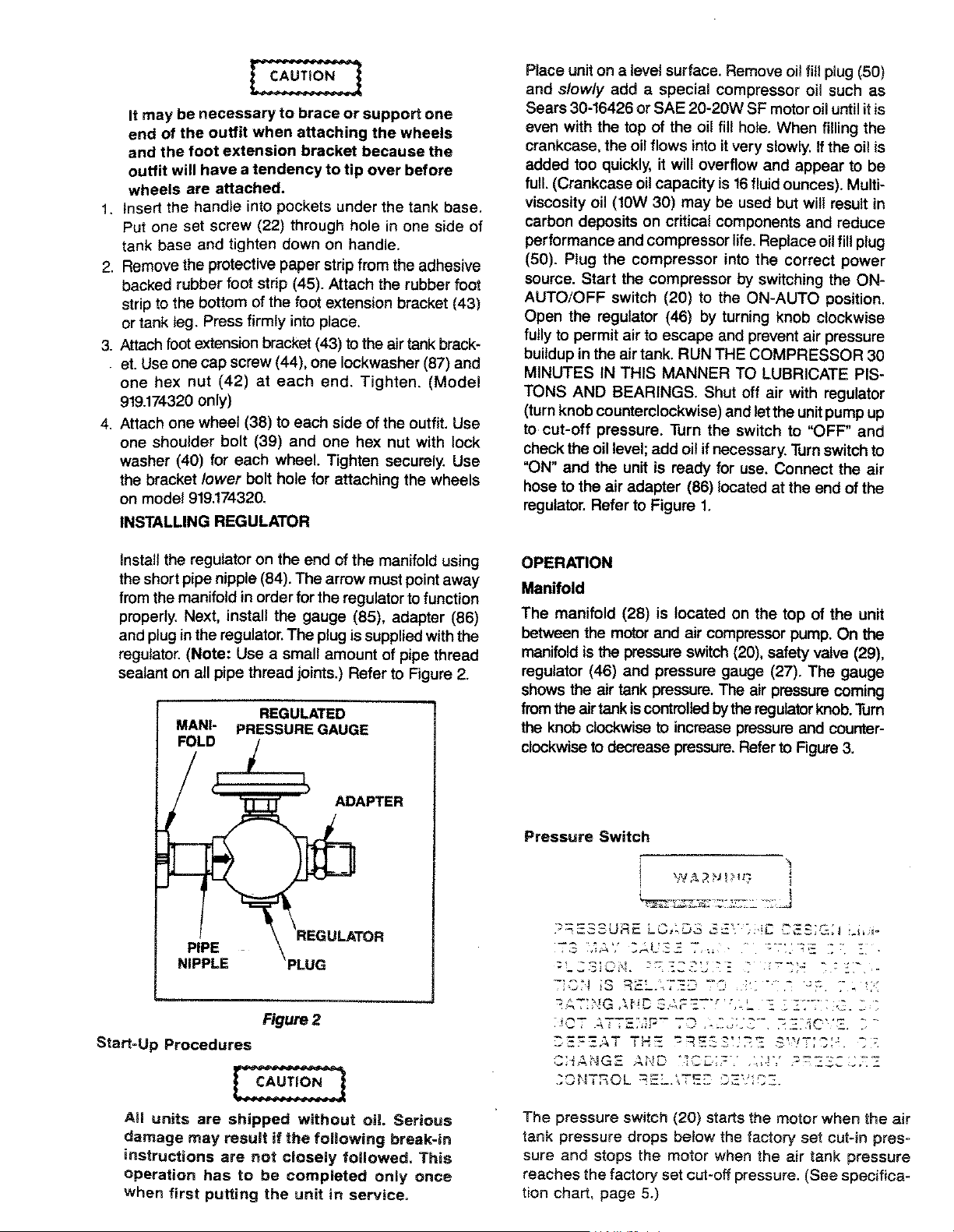
INSTALLING REGULATOR
install the regulator on the end of the manifold using
the short pipe nipple (84). The arrow must point away
from the manifold in order for the regulator to function
properly. Next, install the gauge (85), adapter (86)
and plug in the regulator. The plug is supplied with the
regulator. (Note: Use a small amount of pipe thread
sealant on all pipe thread joints.) Refer to Figure 2.
REGULATED
MANI- PRESSURE GAUGE
FOLD
ADAPTER
REGULATOR
PIPE
NIPPLE
Figure 2
Start=Up Procedures
All units are shipped without oi!. Serious
damage may result if the following break-in
instructions are not closely followed. This
Operation has to be completed only once
when first putting the unit in service.
Place uniton a level surface. Remove oit fill plug (50)
and slowly add a special compressor oil such as
Sears 30-16426 or SAE 20-20W SF motor oil until itis
even with the top of the oil fill hole. When filling the
crankcase, the oil flows into itvery slowly. If the oil is
added too quickly, it wilt overflow and appear to be
full. (Crankcase oil capacity is 16 fluid ounces). Multi-
viscosity oil (10W 30) may be used but will result in
carbon deposits on critical components and reduce
performance and compressor life. Replace oil fill plug
(50). Plug the compressor into the correct power
source• Start the compressor by switching the ON-
AUTO/OFF switch (20) to the ON-AUTO position.
Open the regulator (46) by turning knob clockwise
fully to permit air to escape and prevent air pressure
buildup in the air tank. RUN THE COMPRESSOR 30
MINUTES IN THIS MANNER TO LUBRICATE PIS-
TONS AND BEARINGS. Shut off air with regulator
(turn knob counterclockwise) and let the unit pump up
to cut-off pressure. Turn the switch to "OFF" and
check the oil level; add oil if necessary. Turn switch to
"ON" and the unit is ready for use. Connect the air
hose to the air adapter (86) located at the end of the
regulator. Refer to Figure 1.
OPERATION
Manifold
The manifold (28) is located on the top of the unit
between the motor and air compressorpump. On the
manifold is the pressure switch (20), safety valve (29),
regulator (46) and pressure gauge (27). The gauge
shows the air tank pressure. The air pressure coming
from the airtank iscontrolled bythe regulator knob. Turn
the knob clockwise to increase pressure and counter-
clockwise to decrease pressure. Refer to Figure 3.
Pressure Switch
:'_gS;C_I. "_= ....... - ..........
7_C I iS .......... = ...... " - _ " ""
:' &T:b!G AHC _ 1_=-'f ....
" +'-ATTE:,';F"-_ ............ ' ....
H-F-%T TH- -_=-_............ =w--'"•: _-
........ qG,- AND ............ '.............
The pressure switch (20) starts the motor when the air
tank pressure drops below the factory set cut-in pres-
sure and stops the motor when the air tank pressure
reaches the factory set cut-off pressure. (See specifica-
tion chart, page 5.)
Loading ...
Loading ...
Loading ...