Loading ...
Loading ...
Loading ...
THiS MANUAL iS DESIGNED TO MAKE iT AS EASY AS POSSIBLE
FOR YOU TO SET UP, OPERATE AND MAINTAIN
YOUR NEW AIR COMPRESSOR
GENERAL INFORMATION
ASSEMBLY INSTRUCTIONS
You have purchased a complete portable compressor
outfit consisting of a 2 cylinder single-stage air
compressor with air tank, air hose assembly, wheels
and handle. You will also find an air chuck and a
helpful "Power Painting With Sprayers" booklet. The
2 horsepower unit has a removable foot extension
bracket which allows for stationary mounting.
These units can be used for operating caulking guns,
grease guns, air brushes, sandblasters, air tools, etc., or
inflating tires and plastic toys, spraying weed killer,
insecticides, etc.
GENERAL DESCRIPTION OF OPERATION
To compress air, the pistons move up and down in the
cylinder. On the downstroke, air is drawn in through the
air intake valve. The exhaust valve remains closed. On
the upstroke of the piston, air iscompressed. The intake
valves close and compressed air is forced out through
the exhaust valve, through the check valve and into the
air tank. Working air is not available until the compressor
has raised the air tank pressure above that required at
the air outlet. The air intake opening must be kept clear
of obstructions which could reduce air delivery of the
compressor.
Tools Needed For Assembly
Tools needed are: (1) a 9/ld'socket or open end wrench
for attaching the wheels and hose adapter; and (2) an
adjustable wrench for attaching the pressure regulator,
and (3) a 7/16"open end wrench for attaching the air
pressure gauge, (4) a 7A6"socket or open end wrench for
attaching the foot extension bracket (2 hp. unit only), (5)
a 3/16"hex key for installing the plug in the regulator and
(6) pipe thread sealant.
Attaching Wheels, Handle, Etc.
i .... i
":""-'- V'HEELS A;_D "b':[[CLE 9£ ;'DT
_F O_qDE [.DEQU;TE .?.LZ,LR,:.;"CE _T,C-
E:LIT"" OR SU_'-'OR_" FOR :J_L! £ "%_,E
U!;- LF OR C.OV';,: ST;!RS /.[:: STZ=S.
TXE U;4ZTr._US- _E L;-TED ©': PL!_-:EE U_
See diagram on page 10 for attaching air pressure
regulator (46), wheels (38), foot extension bracket (43)
and handle (47). Refer to the illustration, page 10, Key
No's. 22, 39, 40, 42, 44, 45, 84, 85 and 86.
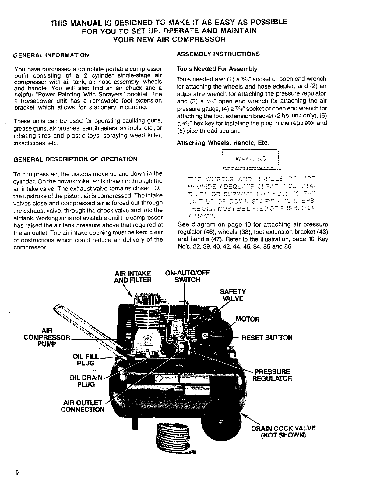
AIR INTAKE
AND FILTER
ON-AUTO/OFF
SWITCH
SAFETY
VALVE
AIR
COMPRESSOR ____
PUMP
BUTTON
0
PLUG
PLUG
RE
REGULATOR
AIR
CONNECTION
DRAIN COCK VALVE
(NOT SHOWN)
6
Loading ...
Loading ...
Loading ...