Loading ...
Loading ...
Loading ...
8
English
• This product is not intended for use by persons (including
children) suffering from diminished physical, sensory or
mental abilities; lack of experience, knowledge or skills
unless they are supervised by a person responsible for their
safety. Children should never be left alone with thisproduct.
Torque Limiting Clutch
All rotary hammerdrills are equipped with a torque limiting
clutch that reduces the maximum torque reaction transmitted
to the operator in case of jamming of a drill bit. This feature
also prevents the gearing and electric motor from stalling.
The torque limiting clutch has been factory-set and cannot
beadjusted.
ASSEMBLY AND ADJUSTMENTS
WARNING: To reduce the risk of serious personal
injury, turn tool off and disconnect tool from power
source before making any adjustments or removing/
installing attachments or accessories. Be sure the
trigger switch is in the OFF position. An accidental start-up
can cause injury.
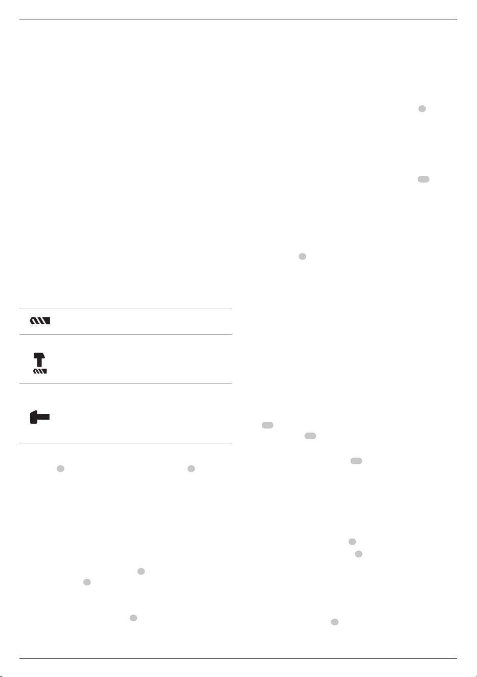
Selecting the Operating Mode
(Fig. B)
The tool can be used in the following operating modes:
Rotary drilling: for screwdriving and for drilling
into steel, wood and plastics
Hammerdrilling: for concrete and masonry
drilling operations.
Bit rotation: non-working position used only to
rotate a flat chisel into the desired position
Hammering only (D25033, D25133, D25134,
D25143, D25144, D25263): for light chipping,
chiselling and demolition applications. In this
mode the tool can also be used as a lever to free
a jammed drillbit.
1. To select the operating mode, press the mode selector
button
5
and rotate the mode selector switch
4
until it
points to the symbol of the requiredmode.
2. Release the mode selector button and check that the mode
selector switch is locked inplace.
WARNING: Do not select the operating mode when the
tool isrunning.
Indexing the Chisel Position (Fig. B)
The chisel can be indexed and locked into differentpositions.
1. Press the mode selector button
5
and rotate the mode
selector switch
4
until it points to the “bit rotation/
hammerdrilling”position.
2. Rotate the chisel to the desiredposition.
3. Set the mode selector switch
4
to the “hammering
only”position.
4. Twist the chisel until it locks inposition.
Inserting and Removing SDS Plus Accessories
(Fig. C)
This tool uses SDS Plus accessories (refer to the inset in Fig.C for
a cross-section of an SDS Plus bit shank). We recommend using
professional accessoriesonly.
1. Clean and grease the bitshank.
2. Insert the bit shank into the SDS Plus tool holder
6
.
3. Push the bit down and turn it slightly until it fits into
theslots.
4. Pull on the bit to check if it is properly locked. The
hammering function requires the bit to be able to move
axially several centimetres when locked in the toolholder.
5. To remove a bit, pull back the tool holder sleeve
10
and
pull out thebit.
WARNING: Always wear gloves when you change
accessories. The exposed metal parts on the tool and
accessory may become extremely hot duringoperation.
Fitting the Side Handle (Fig. D)
The side handle
8
can be fitted to suit both right-handed and
left-handedusers.
WARNING: Do not use the tool without the side handle
properlyassembled.
1. Loosen the sidehandle.
2. For right-handed users: Slide the side handle clamp over
the collar behind the tool holder, handle at theleft.
For left-handed-users: Slide the side handle clamp over
the collar behind the tool holder, handle at theright.
3. Rotate the side handle to the desired position and tighten
thehandle.
Side Handle Work light (Fig.E)
D25144, D25263
The side handle on the D25144 and D25263 has a work
light
15
. The light is battery powered and operated by using
the on/off button
17
.
To replace the worklight’s batteries (CR2032 x 2):
1. Remove battery door screw
16
as shown in FigureE.
2. Replace the battery with the positive face
pointingoutwards.
3. Close the battery compartment and secure thescrew.
Setting the Drilling Depth (Fig. F)
1. Insert the required drill bit as describedabove.
2. Press the depth rod button
9
and keep itdepressed.
3. Fit the depth adjustment rod
7
through the hole in the
depth stopclamp.
4. Adjust the drilling depth asshown.
5. Release the depth stopclamp.
Reversing Lever (Fig. G)
The forward/reverse lever
3
is used to reverse the rotation of
the hammer for backing out fasteners or jammed bits in the
drill-onlyfunction.
Loading ...
Loading ...
Loading ...