Loading ...
Loading ...
Loading ...
-11-
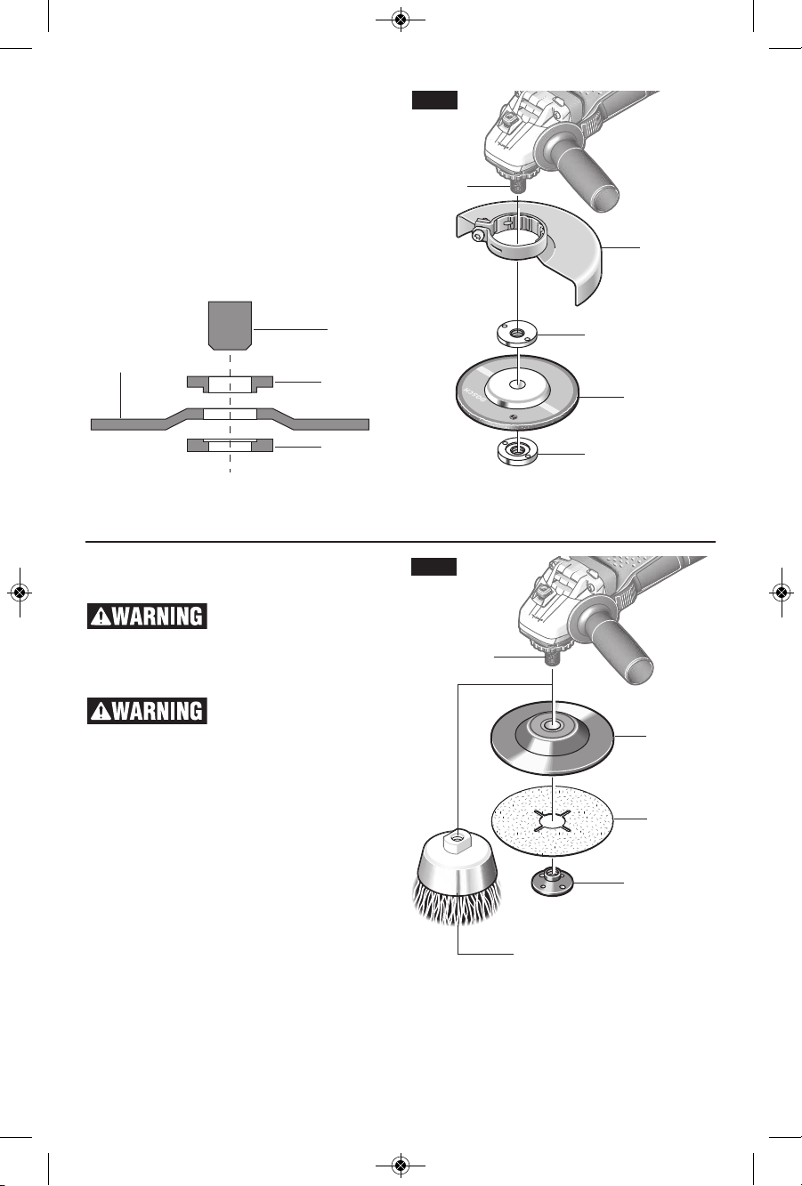
GRINDING WHEEL ASSEMBLY
D
isconnect tool from power source. Be sure
that wheel guard is in place for grinding. Place
BACKING FLANGE and GRINDING WHEEL
on the spindle. Thread on the lock nut and
tighten nut using the supplied lock nut wrench,
while holding the spindle lock in (Fig. 3).
TO REMOVE: Reverse procedure.
Not recommended for use with spin-on
wheels.
LOCK NUT
TYPE 27
GRINDING
WHEEL
BACKING
FLANGE
SPINDLE
TYPE 27
GRINDING
WHEEL
LOCK NUT
SPINDLE
TYPE 27
WHEEL GUARD
BACKING
FLANGE
FIG. 3
SANDING ACCESSORIES ASSEMBLY
BACKING PAD
Before attaching a
backing pad be sure its
maximum safe operating speed is not
exceeded by the nameplate speed of the
tool.
Wheel guard may not be
used for most sanding
operations. Always reinstall wheel guard
when converting back to grinding operations.
TO INSTALL BACKING PAD AND
SANDING DISC
Disconnect tool from power source.
Attach hand guard (Fig. 1). Set the tool on its
top side (spindle up). Place the rubber
backing pad onto the spindle shaft. Center
the sanding disc on top of the backing pad.
Insert the lock nut through the disc and
thread onto the spindle as far as you can
with your fingers. Press in the spindle lock,
then tighten the backing pad securely with
lock nut wrench (Fig. 4).
TO REMOVE: Reverse procedure.
SANDING
DISC
BACKING
PAD
LOCK NUT
WIRE
BRUSH
SPINDLE
FIG. 4
BM 2610043215_GWS8-45 1/29/16 1:58 PM Page 11
Loading ...
Loading ...
Loading ...