Eaton 5PX
Advanced User Guide
Copyright © 2021 EATON
All rights reserved.
614-40095-00
5PX1000RTG2
5PX1000RTNG2
5PX1500RTG2
5PX1500RTNG2
5PX2000RTG2
5PX2000RTNG2
5PX2000RT3UNG2
5PX3000RTG2
5PX3000RTNG2
5PX3000RT3UNG2
5PXEBM48RTG2
5PXEBM72RTG2
5PXEBM72RT3UAG2
614-40095-00
2
Special symbols
The following are examples of symbols used on the UPS or accessories to alert you to importantinformation:
DANGER: Dangerous voltage levels are present within the UPS. The UPS has its own internal power
source (the battery). Consequently, the power outlets may be energized even if the UPS is
disconnected from the AC power source.
Important instructions that must always be followed.
CAUTION: Batteries present a risk of energy or electrical shock or burn from high short circuit current.
Observe proper precaution. Batteries may contain HIGH VOLTAGE and CORROSIVE, TOXIC and
EXPLOSIVE substances.
Information, advice, help.
Read the documentation provided.
Disconnect input plug.
Before maintenance, first shut down the UPS then disconnect the AC power source, internal and
external batteries then discharge capacitors by pressing the ON button and wait 5 minutes.
This equipment should only be used in a dry indoor environment.
Operating range of temperature.
Operating range of humidity.
The UPS and their batteries must be kept in a ventilated place.

614-40095-00
3
Table of Contents
1 Introduction ................................................................................................................... 5
1.1 Environmental protection .................................................................................................................... 5
1.2 Benefits.................................................................................................................................................. 6
2 Presentation................................................................................................................... 7
2.1 Standard installation ............................................................................................................................ 7
2.2 Rear panel.............................................................................................................................................. 8
2.3 Optional accessories............................................................................................................................. 9
3 Installation ..................................................................................................................... 9
3.1 Inspecting the equipment .................................................................................................................... 9
3.2 Recommended positions.................................................................................................................... 11
3.3 Connecting the internal battery......................................................................................................... 13
3.4 EBM connection .................................................................................................................................. 13
3.5 UPS connection................................................................................................................................... 15
3.6 Connection with a FlexPDU (Power Distribution Unit) optional module......................................... 15
3.7 Connection with a HotSwap MBP (Maintenance ByPass) optional module .................................... 15
4 Interfaces and communication ................................................................................... 17
4.1 Control panel....................................................................................................................................... 17
4.2 LCD description................................................................................................................................... 18
4.3 Display functions................................................................................................................................. 19
4.4 User settings........................................................................................................................................ 21
4.5 Communication ports......................................................................................................................... 24
4.6 UPS remote control functions............................................................................................................ 26
4.7 Eaton Intelligent Power Software suite ............................................................................................. 29
4.8 Cybersecurity ...................................................................................................................................... 29
5 Operation ..................................................................................................................... 29
5.1 Start-up and normal operation .......................................................................................................... 29
5.2 Starting the UPS on battery................................................................................................................ 30
5.3 UPS shutdown..................................................................................................................................... 30
5.4 Operating modes ................................................................................................................................ 30
5.5 Return of AC input power ................................................................................................................... 31
5.6 Retrieving the event log...................................................................................................................... 31

614-40095-00
4
5.7 Retrieving the fault log ....................................................................................................................... 31
6 UPS maintenance......................................................................................................... 31
6.1 Equipment care................................................................................................................................... 31
6.2 Storing the equipment........................................................................................................................ 31
6.3 When to replace batteries................................................................................................................... 32
6.4 Replacing batteries ............................................................................................................................. 32
6.5 Replacing the UPS equipped with a HotSwap MBP .......................................................................... 34
6.6 Recycling the used equipment........................................................................................................... 34
7 Troubleshooting........................................................................................................... 34
7.1 Typical alarms and faults.................................................................................................................... 35
7.2 Silencing the alarm ............................................................................................................................. 37
7.3 Service and support............................................................................................................................ 37
8 Specification and technical characteristics................................................................ 37
8.1 UPS model list ..................................................................................................................................... 38
8.2 Extended Battery Module model list.................................................................................................. 38
8.3 Electrical input .................................................................................................................................... 39
8.4 Electrical input connections............................................................................................................... 39
8.5 Electrical output.................................................................................................................................. 40
8.6 Electrical output connection.............................................................................................................. 40
8.7 Battery ................................................................................................................................................. 41
8.8 Environmental and safety .................................................................................................................. 41
9 Glossary ........................................................................................................................ 42

614-40095-00
5
•
•
•
1 Introduction
Thank you for selecting an Eaton 5PXproduct to protect your electrical equipment.
TheEaton 5PXrange has been designed with the utmost care. We recommend that you take the time to read this
advanced user guide to take full advantage of the many features of your UPS (Uninterruptible Power System).
Before installing yourEaton5PX,please read the information and safety instructions provided. Follow the instructions in
the quick start guide and if necessary, refer to this advance user guide.
To discover the entire range ofEatonproducts, we invite you to visit ourweb siteateaton.comor
contactyourEatonlocal representative.
NOTE: This equipment has been tested and found to comply with the limits for a Class B digital device, pursuant to part
15 of the FCC Rules. These limits are designed to provide reasonable protection against harmful interference in a
residential installation. This equipment generates, uses and can radiate radio frequency energy and, if not installed and
used in accordance with the instructions, may cause harmful interference to radio communications. However, there is no
guarantee that interference will not occur in a particular installation. If this equipment does cause harmful interference to
radio or television reception, which can be determined by turning the equipment off and on, the user is encouraged to try
to correct the interference by one or more of the following measures:
-Reorient or relocate the receiving antenna.
-Increase the separation between the equipment and receiver.
-Connect the equipment into an outlet on a circuit different from that to which the receiver is connected.
-Consult the dealer or an experienced radio/TV technician for help.
UPS employing batteries with min. V-2 case are intended for use in computer room as defined in the standard for the
Protection of Information Technology Equipment, ANSI/NFPA 75.
UPS employing batteries with HB case are intended not for use in a computer room as defined in the standard for the
Protection of Information Technology Equipment, ANSI/NFPA 75.
Supplier's Declaration of Conformity of Federal Communications Commission Statement
This device complies with Part 15 of the FCC Rules. Operation is subject to the following two conditions:
(1) this device may not cause harmful interference, and
(2) this device must accept any interference received, including interference that may cause undesired operation.
For questions regarding this FCC SDoC declaration, contact Eaton Corporation by telephone or through the Internet.
Eaton Corporation
8609 Six Forks Road,
Raleigh, NC 27615, USA
Telephone: 800-356-5794
This UPS can be used in IT power system. This UPS complies with the IP20 protection type.
1.1 Environmental protection
Eatonhas implemented an environmental-protection policy. Products are developed according to an eco-design
approach.
Substances
This product does not contain CFC and HCFC. This product does not contain asbestos. This product is compliant with
regulations on the restriction of the use of substances in electrical and electronic equipment.
Packaging
To improve waste treatment and facilitate recycling, separate the various packing components.
The cardboard we use comprises over 50% of recycled cardboard.
Plastic bags are made of polyethylene.
Packing materials are recyclable and bear the appropriate identification symbol.

614-40095-00
6
Materials Abbreviations
Number in the symbols
Polyethylene terephthalate PET 01
High-density polyethylene HDPE 02
Polyvinyl chloride PVC 03
Low-density polyethylene LDPE 04
Polypropylene PP 05
Polystyrene PS 06
Follow all local regulations for the disposal of packing materials.
End of life
Eatonwill process products at the end of their service life in compliance with local regulations. Eatonworks with
companies in charge of collecting and eliminating our products at the end of their service life.
Product
The product is made up of recyclable materials. Dismantling and destruction must take place in compliance with all local
regulations concerning waste. At the end of its service life, the product must be transported to a processing center for
electrical and electronic waste.eaton.com/recycling
Battery
The product contains lead-acid batteries that must be processed according to applicable local regulations concerning
batteries. The battery may be removed to comply with regulations and in view of correct disposal.
1.2 Benefits
The Eaton 5PXuninterruptible power system (UPS) protects your sensitive electronic equipment from themost common
power problems, including power outages, voltagesags, impulsive transients, line noise, and long-term under and over
voltage conditions.
Power outages can occur when you least expect it and power quality can be erratic. These power problemshave the
potential to corrupt critical data, destroy unsaved work sessions, and damage hardware - causinghours of lost
productivity and expensive repairs.
With the Eaton 5PX, you can safely eliminate the effects of power disturbances and guard the integrityof your
equipment. Providing outstanding performance and reliability, the Eaton 5PX’s unique benefitsinclude:
• ABM® technology that uses advanced battery management to increase battery service life, optimize recharge time, and
provide a warning before the end of useful battery life
• Standard communication options:one RS-232 communication port, one USB communication port, relay output
contacts
• Optional connectivity cards with enhanced communication capabilities
• Extended runtime with up to four Extended Battery Modules (EBMs) per UPS
• Remote On/Off control
• Backed by worldwide agency approvals
• Remote firmware upgrade capability.
614-40095-00
7
2 Presentation
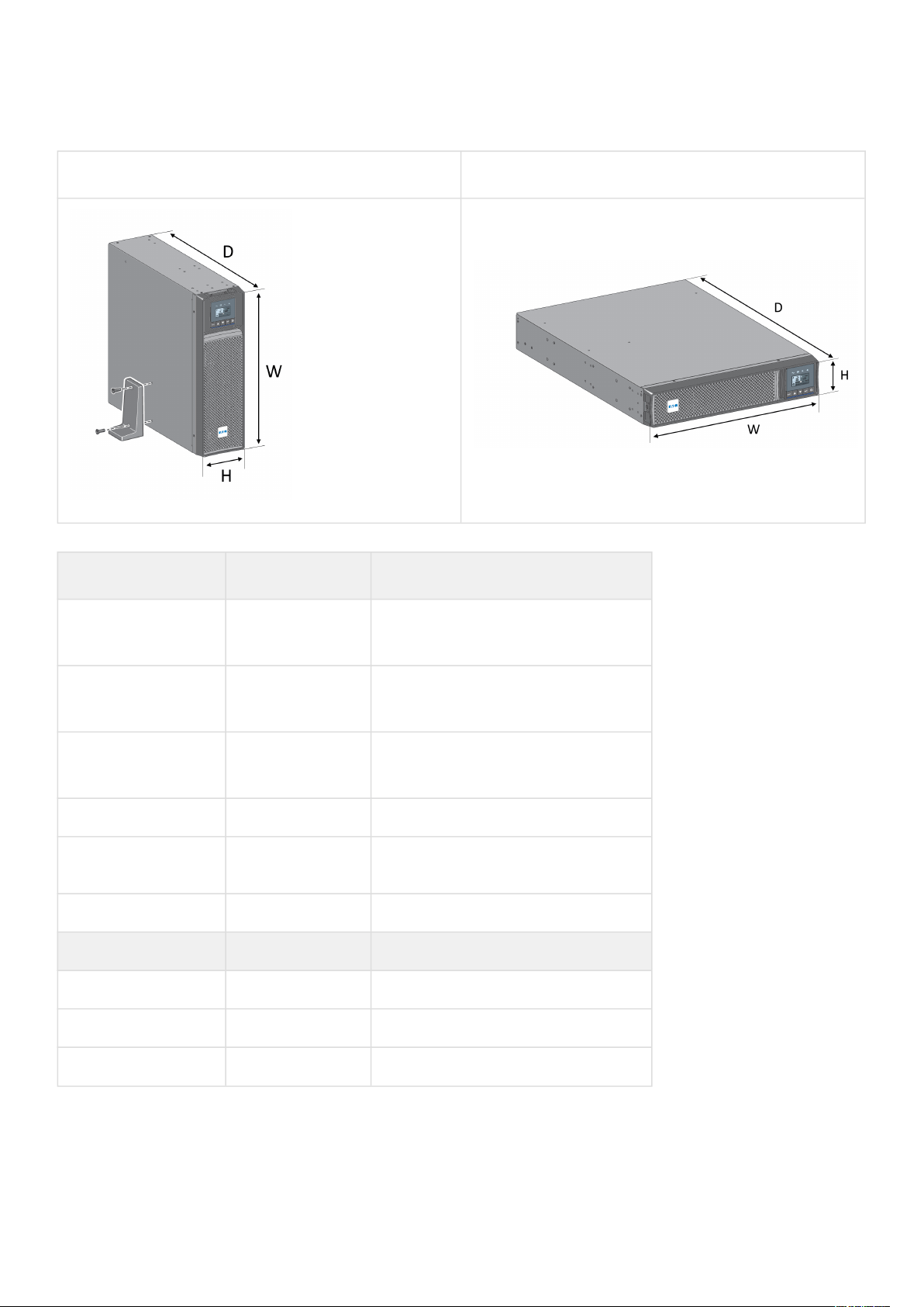
2.1 Standard installation
Tower installation Rack installation
Weights and dimensions
Description (UPS) Weights (lb / kg)
Dimentions (inch / mm) D x W x H
5PX1000RTG2
5PX1000RTNG2
44.5 / 20.2 17.6x17.2x3.4 / 448x438x85.5
5PX1500RTG2
5PX1500RTNG2
50.7 / 23.0 17.6x17.2x3.4 / 448x438x85.5
5PX2000RTG2
5PX2000RTNG2
65.3 / 29.6 23.7x17.2x3.4 / 603x438x85.5
5PX2000RT3UNG2 64.2 / 29.1 19x17.2x5.1 / 483x438x129
5PX3000RTG2
5PX3000RTNG2
74.5 / 33.8 23.7x17.2x3.4 / 603x438x85.5
5PX3000RT3UNG2 72.8 / 33.0 19x17.2x5.1 / 483x438x129
Description (EBM) Weights (lb / kg) Dimentions (inch / mm) D x W x H
5PXEBM48RTG2 61.3 / 27.8 17.6x17.2x3.4 / 448x438x85.5
5PXEBM72RTG2 89.1 / 40.4 23.7x17.2x3.4 / 603x438x85.5
5PXEBM72RT3UAG2 87.5 / 39.7 19x17.2x5.1 / 483x438x129
614-40095-00
8
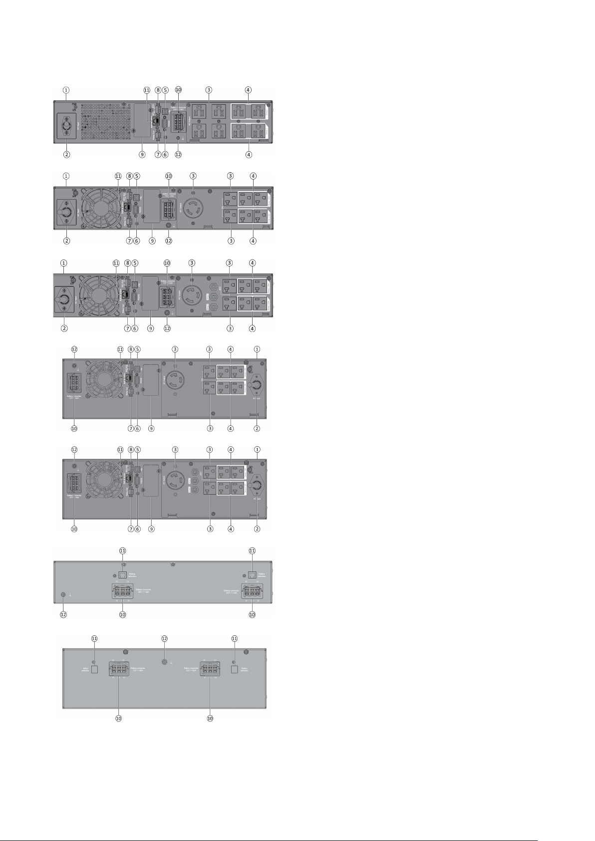
2.2 Rear panel
5PX1000RTG2/5PX1000RTNG2
5PX1500RTG2/5PX1500RTNG2
5PX2000RTG2/5PX2000RTNG2
5PX3000RTG2/5PX3000RTNG2
5PX2000RT3UNG2
5PX3000RT3UNG2
5PXEBM48RTG2 - 5PXEBM72RTG2
5PXEBM72RT3UAG2
① UPS
② Input AC power source
③Primary group (critical equipment)
④Outlet group (programmable outlets)
⑤ USB communication port
⑥RS232 communication port
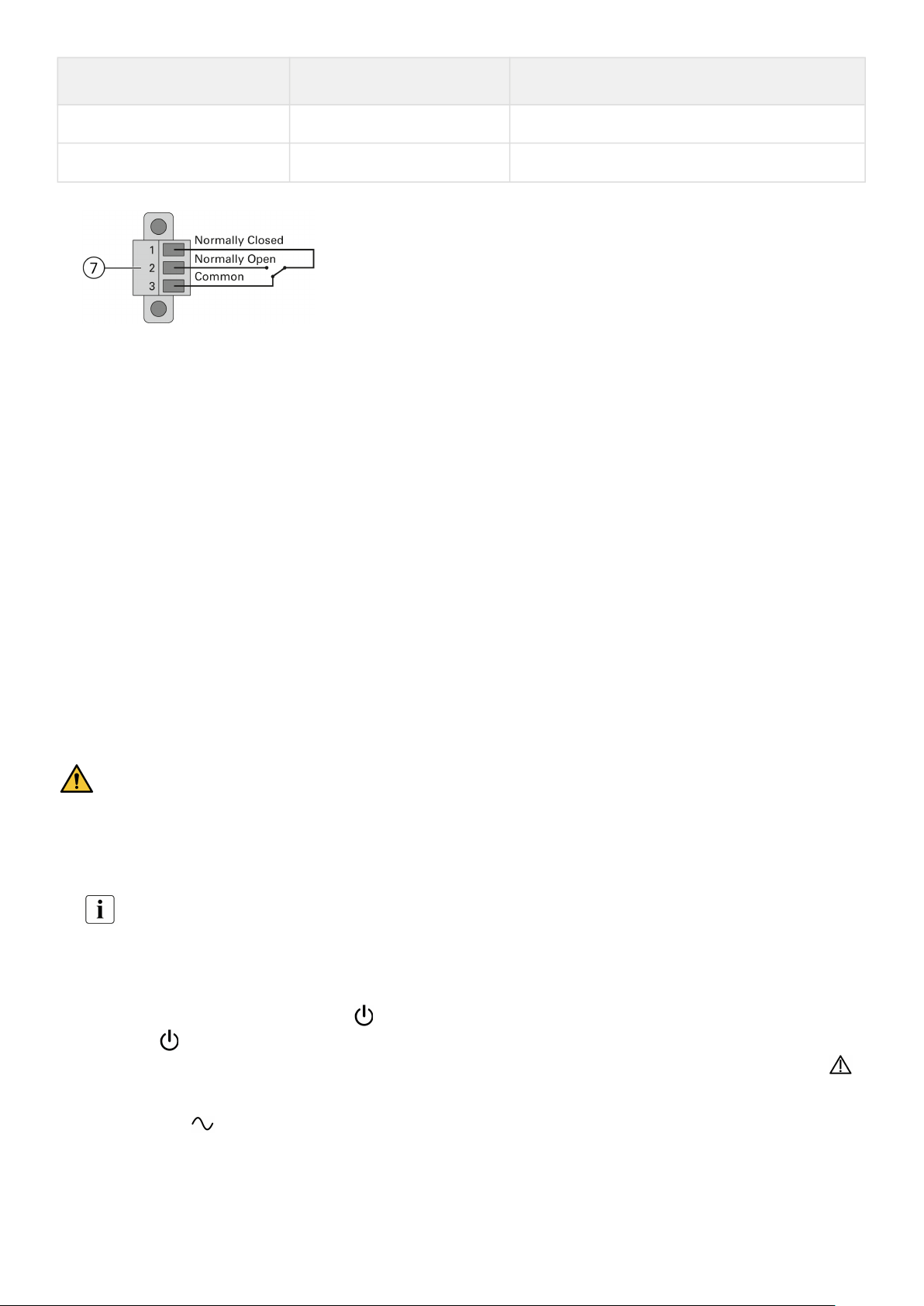
⑦Relay output contact
⑧Connector for ROO (Remote On/Off) control and RPO
(Remote Power Off)
⑨Slot for optional communication card
⑩Connector for additional External Battery Module
⑪Connector for automatic recognition of an additional
battery module
⑫ Ground screw

614-40095-00
9
1.
2.
2.3 Optional accessories
Part number Description
5PXEBM48RTG2
5PXEBM72RTG2
5PXEBM72RT3UAG2
Extended Battery Module
Network-M2
Eaton Gigabit Network Card (SNMP v1/v3 and IP v4/v6 // Ethernet
10/100/1000BaseT)
INDGW-M2 Eaton Industrial Gateway Card (Modbus TCP / RTU)
Relay-MS Eaton Relay card (1 x RS232 or 5 x Relay output)
INDRELAY-MS
Eaton Industrial relay card (5x relay outputs with dry contacts for
remote alarm information)
EMPDT1H1C2
Environmental Monitoring Probe Gen2
Compatible with : Gigabit Network Card (Network-M2) / Industrial
Gateway Card (INDGW-M2) / Eaton ePDU G3/G3+
EHBPL1500R-PDU1U
EHBPL2000R-PDU1U
EHBPL3000R-PDU1U
HotSwap external maintenance bypass (6) 5-15R
HotSwap external maintenance bypass (6) 5-20R
HotSwap external maintenance bypass (5) 5-20R
EFLXL1500R-PDU1U
EFLXL2000R-PDU1U
EFLXL2000R-PDU1UL
EFLXI3000R-PDU1UIEC
FlexPDU (12) 5-15R
FlexPDU (12) 5-20R
FlexPDU (5) L5-20R
FlexPDU (12) C13, (1) C19
3 Installation
3.1 Inspecting the equipment
If any equipment has been damaged during shipment, keep the shipping cartons and packing materials for the carrier or
place of purchase and file a claim for shipping damage. If you discover damage after acceptance, file a claim for
concealed damage.
To file a claim for shipping damage or concealed damage:
File with the carrier within 15 days of receipt of the equipment;
Send a copy of the damage claim within 15 days to your service representative.
Check the battery recharge date on the shipping carton label. If the date has passed and the batteries were never
recharged, do not use the UPS. Contact your service representative.

614-40095-00
10
Package content
Verify that the following additional items are included
with the UPS:
① UPS
⑬ Connection cable to AC power source
⑮RS232 communication cable
⑯USB communication cable
⑰ Safety instructions
⑱Quick start
⑳Rack kit for 19-inch 4-post enclosures
㉑Two supports for tower position (tower feet)
㉒Communication card (optional)
㉓ FlexPDU module(optional)
㉕HotSwap MBP module (optional)
614-40095-00
11
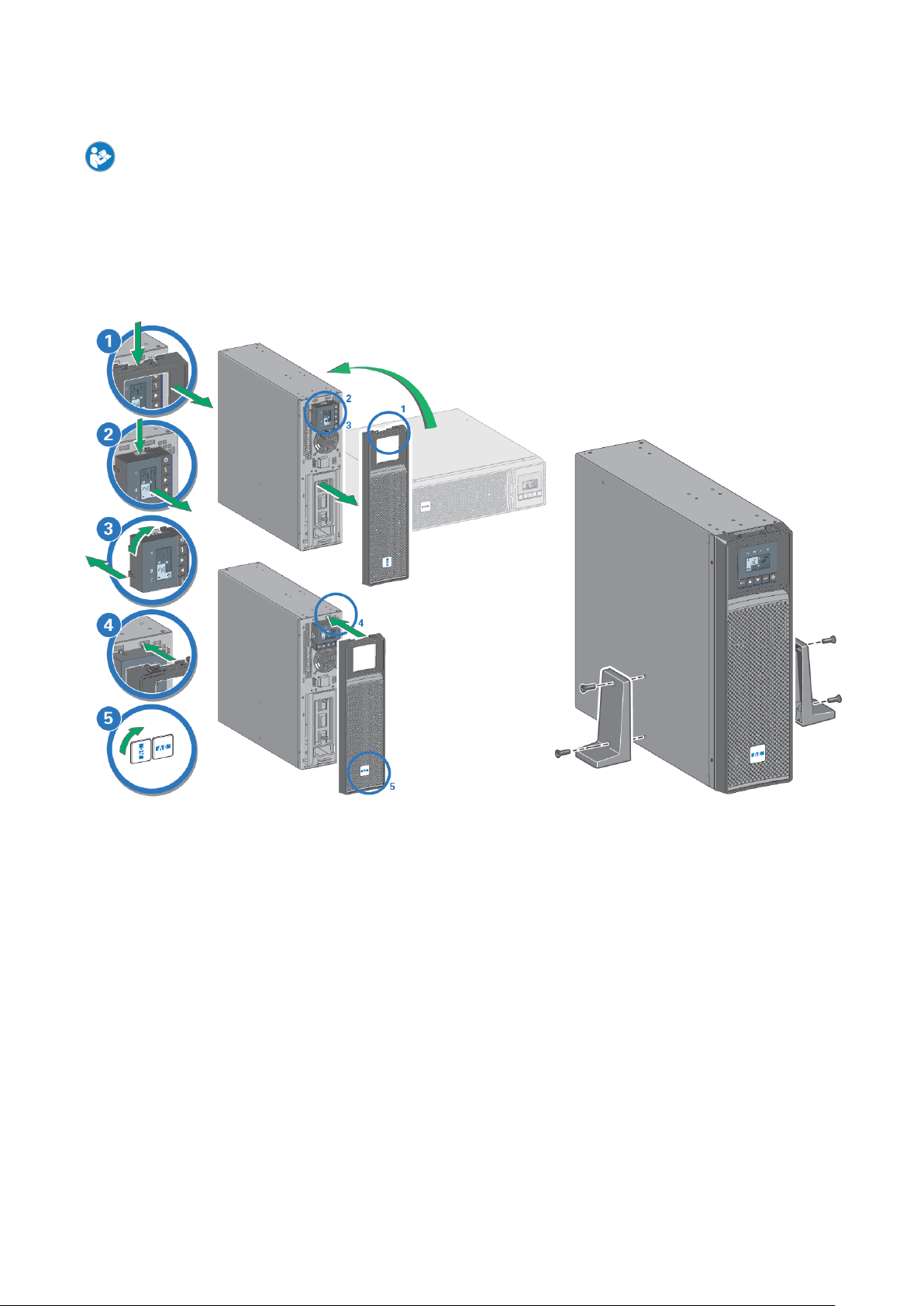
3.2 Recommended positions
Installation in tower position
If you ordered other UPS accessories, refer to specific user manuals to check the tower installation with the UPS.
To install the UPS:
Place the UPS on a flat, stable surface in its final location.Always keep 6" or 150 mm of free space behind the UPS rear
panel for ventilation.
If installing additional EBM, place them next to the UPS in their final location.
Follow steps 1 to 5 to adjust the orientation of the LCD panel and of the logo.
614-40095-00
12
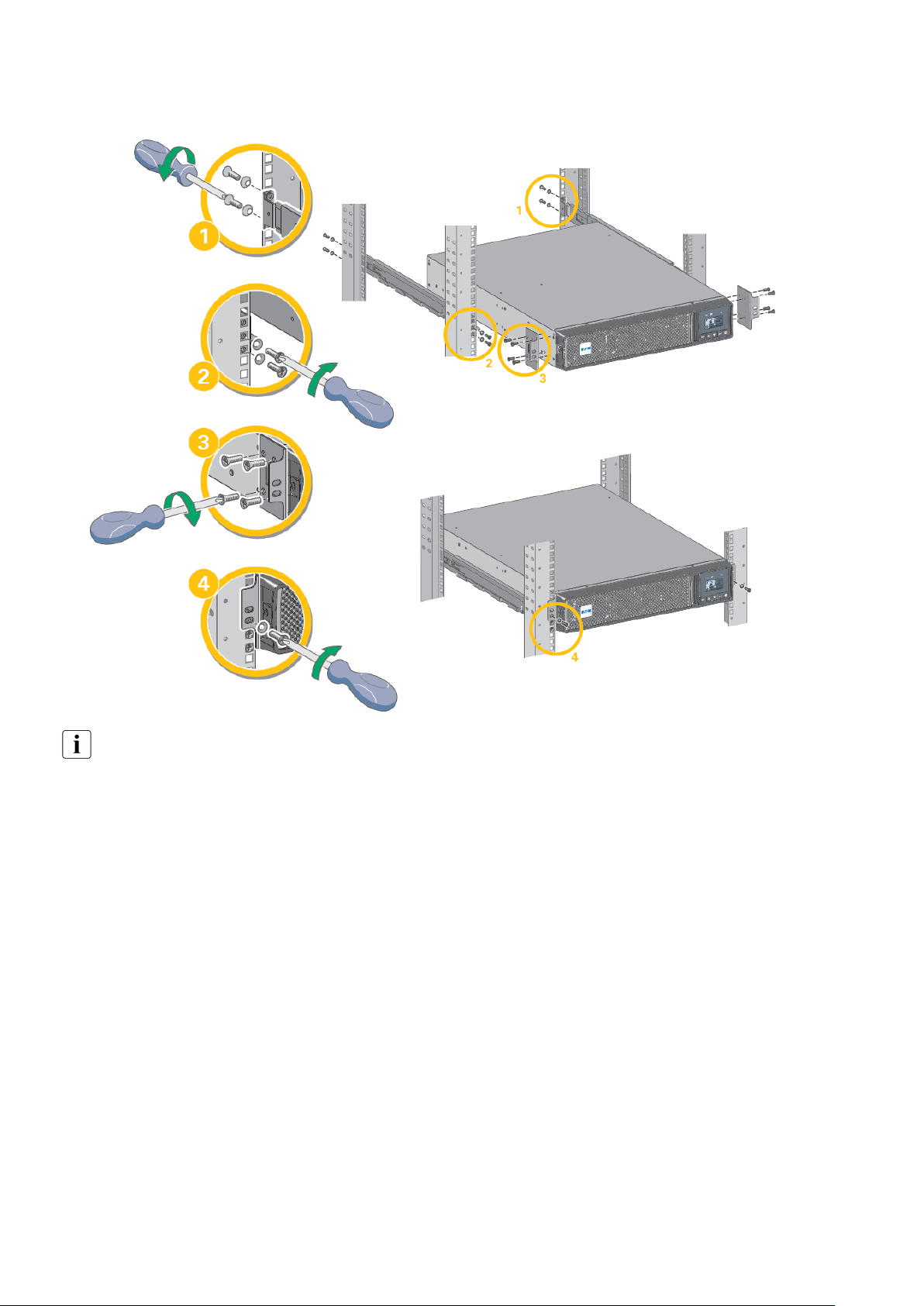
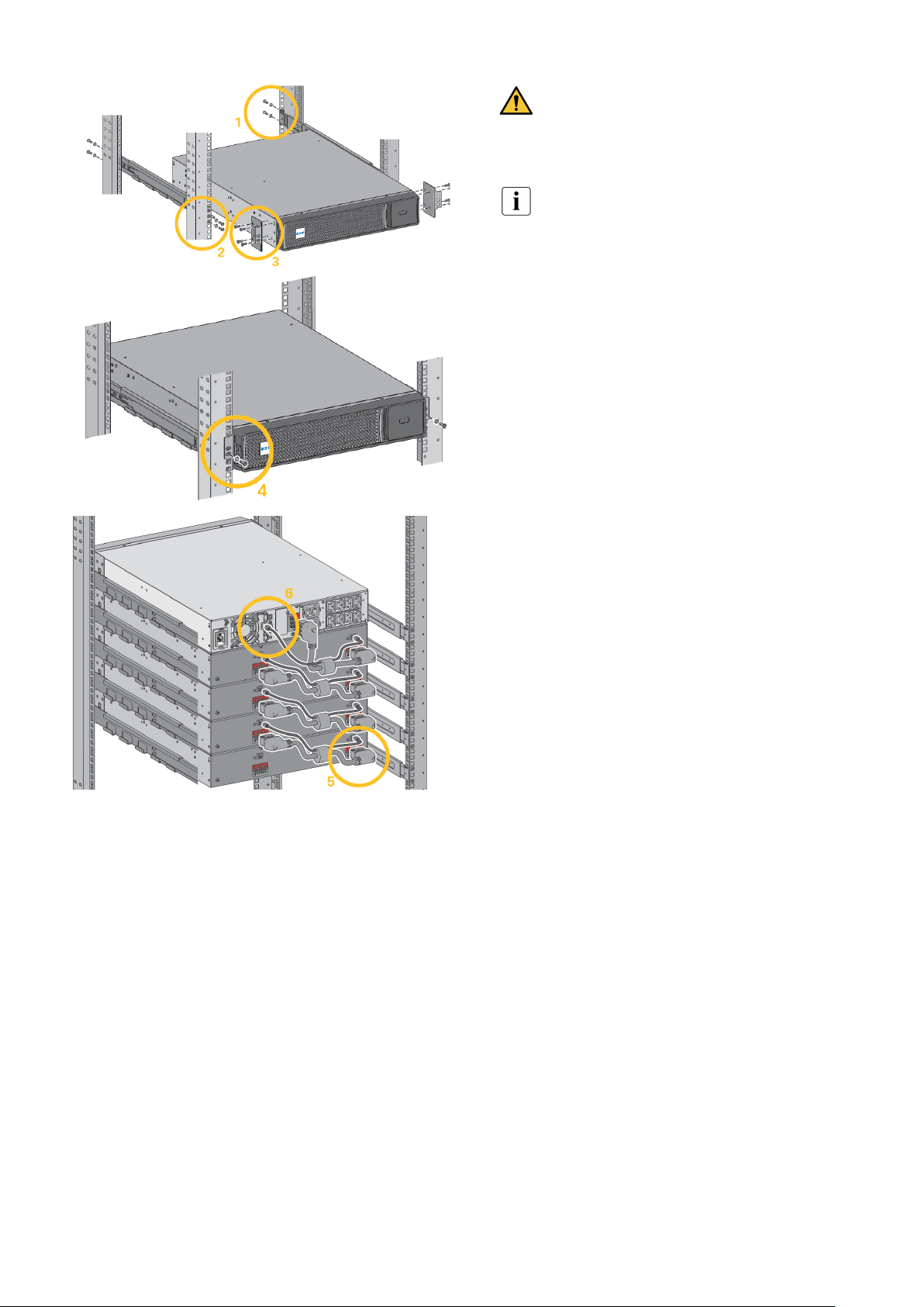
Installation in rack position
Follow steps 1 to 4 for module mounting on the rails.
The rails and necessary hardware are supplied by Eaton.
614-40095-00
13
1.
2.
3.
3.3 Connecting the internal battery
A small amount of arcing may occur when
connecting the internal batteries. This is normal and will
not harm personnel. Connect the cables quickly and
firmly.
Remove the front panel by pressing on both sides of
the panel.
Connect the two battery connectors together.
Replace the front panel.
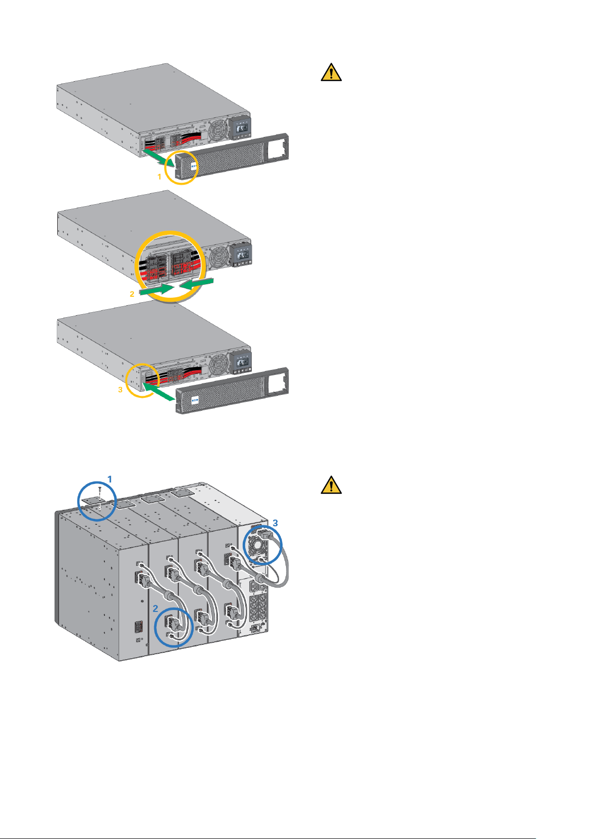
3.4 EBM connection
Tour installation
A small amount of arcing may occur when
connecting an EBM to the UPS. This is normal and will
not harm personnel. Insert the EBM cable into the UPS
battery connector quickly and firmly.
1.Attach the UPS and the EBMs to each other using the
supplied mounting plate. Up to 4 EBMs may be
connected to the UPS.
2. Connect the EBMs power cable and the attached
battery detection cable as shown in the picture.
3. Verify that the EBM connections are tight and that
adequate bend radius and strain relief exist for each
cable.
614-40095-00
14
Rack installation
A small amount of arcing may occur when
connecting an EBM to the UPS. This is normal and will
not harm personnel. Insert the EBM cable into the UPS
battery connector quickly and firmly.
To increase stability, it is preferable to place the
EBM below the UPS.
1. Fix the rail on the back of the rack.
2. Fix the rail on the front of the rack using the two holes
at the bottom.
3. Fix the ears plate to the UPS.
4. Place the UPS on the rails and fix the ears plate to the
top hole of the rail.
5. Connect the EBM power cable as shown in the picture.
6. Connect the RJ45 battery detection cable of the first
EBM between the EBM and the UPS connector "Batt
detection" (11). For any additional EBM, connect the
battery detection cable to the previous EBM.
Verify that the EBM connections are tight and that
adequate bend radius and strain relief exist for each
cable.
614-40095-00
15
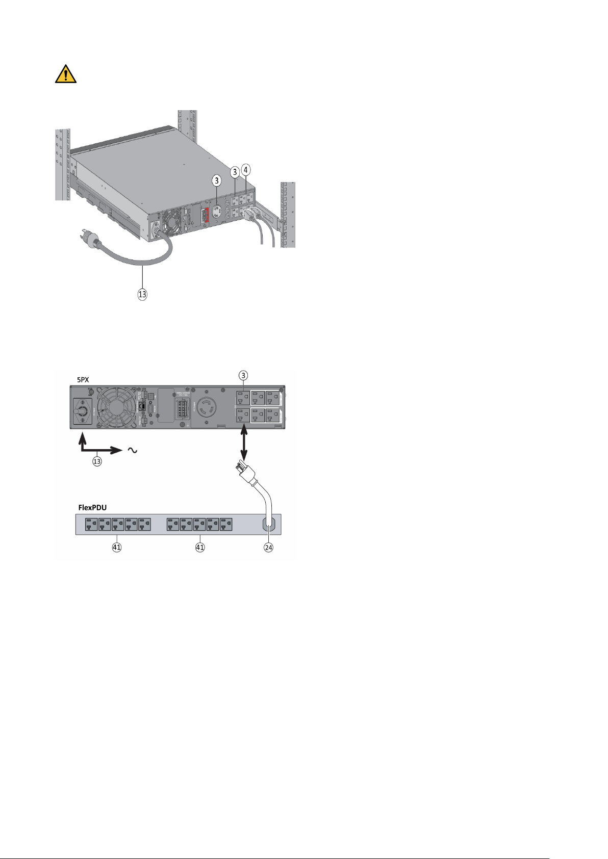
3.5 UPS connection
Check that the indications on the name plate located on the back of the UPS correspond to the AC-power source
and the true electrical consumption of the total load.
1.Connect the UPS input cable (13) to the AC power
source.
2.Connect the loads to the UPS.It is preferable to
connect thepriority loads to the outletsmarked (3) and
the non-priorityloads to the outlets Group1, Group2 (4)
that can be programmed.
For the 5PX2000/ 3000 models, connect any high-power
devicesor matching Power Distribution Unit (PDU) to
theL5-20R or L5-30Routlet.
3.To program shutdown and startup of the Group1 and
Group2 outlets in order to extend battery runtime and
perform scheduled shutdowns, please see the "In/Out
settings" section.
3.6 Connection with a FlexPDU (Power Distribution Unit) optional module
1.Connect the UPS power cord (13) to the AC power
source.
2.Connect the input cord of the FlexPDU module (24) to
one of the UPS outlets (3).
3.Connect the equipment to the outlets (41) on the
FlexPDU module. These outlets differ, depending on the
version of the FlexPDU module.
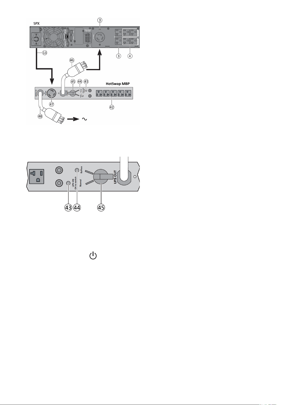
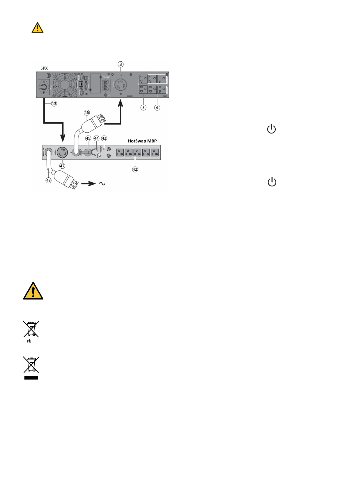
3.7 Connection with a HotSwap MBP (Maintenance ByPass) optional module
The HotSwap MBP module makes it possible to service or even replace the UPS without affecting the connectedloads
(HotSwap function).
614-40095-00
16
1.Connect the input socket (48) onthe HotSwap MBP
module to theAC power source.
2.Connect the UPS input power cord (13) to the
receptacle "UPS Input" (47) of the HotSwap MBP
module.
3.Connect the "UPS Output" cable (46) of the HotSwap
MBP module to the outlet (3) of the UPS .
4. Connect the equipment to the outlets(42) on the
HotSwapMBP module.
These outlets differ,depending on the version of
theHotSwap MBP module.
Caution :Do not use UPS outlets(4) to supply
equipmentbecause use of switch (45) on theHotSwap
MBP module would cutsupply to the equipment.
HotSwap MBP module operation
The HotSwap MBP module has a rotaryswitch (45) with
two positions:
Normal: the load is supplied by the UPS,LED (43) is on.
Bypass: the load is supplied directly bythe AC power
source. LED (44)is on.Load is not protected.
UPS start-up with the HotSwap MBP module
1. Check that the UPS is correctly connected to the HotSwap MBP module.
2.Start the UPS by pressing the button on the UPScontrol panel. LED (43) "UPS ON - OK to switch"on the HotSwap
MBP module goes ON (otherwise,there is a connection errorbetween the HotSwap MBP module and the UPS).
3. Set switch (45) to Normal position.The red LED onthe HotSwap MBP module goes OFF.
HotSwap MBP module test
1. Set switch (45) to Bypass position and check that the load is still supplied.
2. Set switch (45) back to Normal position.
614-40095-00
17
4 Interfaces and communication
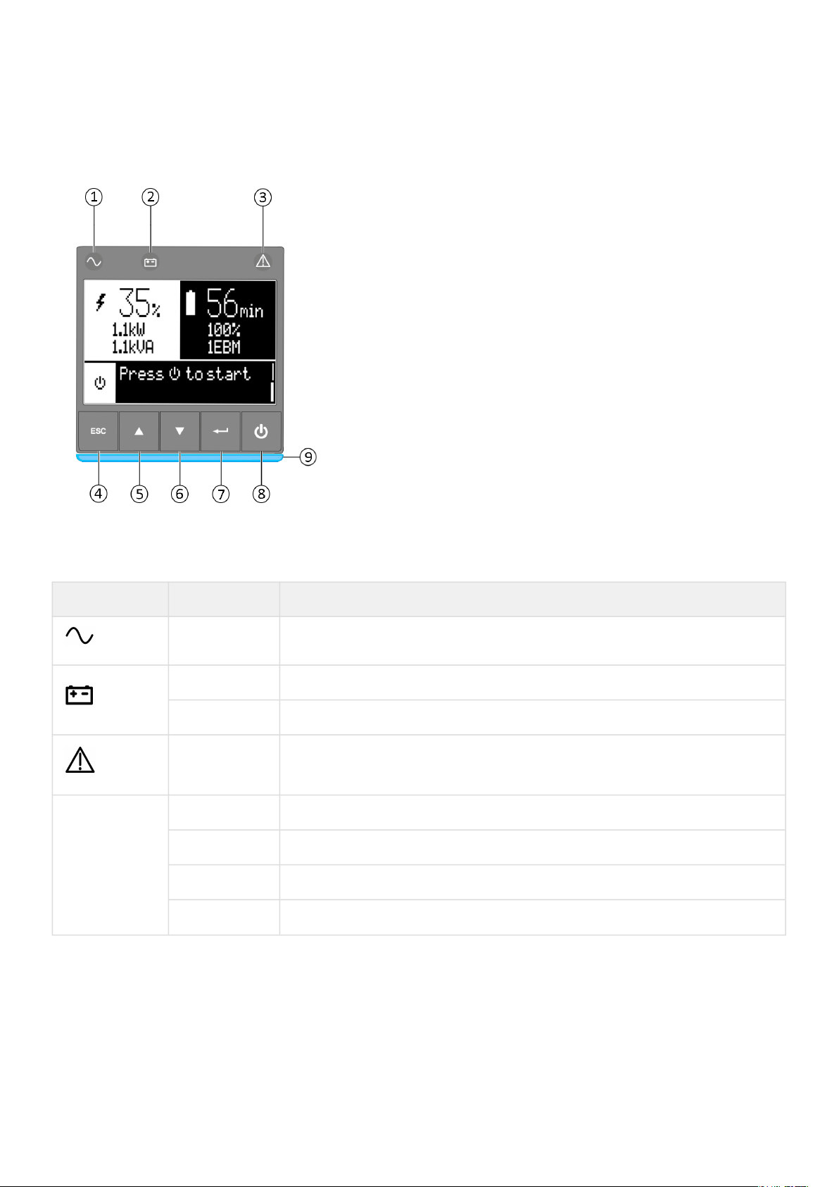
4.1 Control panel
The screen provides useful information about the UPS itself, load status,events, measurements and settings.
The LED bar ⑨ has been implemented to provide a quick visual reference of UPS status "at-a-glance".
① Power ON indicator (green)
② On battery indicator (yellow)
③ Alarm Indicator (red)
④Escape
⑤ Up
⑥ Down
⑦ Enter
⑧ On/Off button
⑨ Led bar
Led indicator
The following table shows the indicator status and description :
Indicator Status Description
Green
On The UPS is "On" and the load is protected.
Yellow
On The UPS is in battery mode and the load is protected.
Flashing The battery voltage is below the warning level.
Red
On
The UPS has an active alarm or fault. See troubleshooting page for additional
information.
Led bar
Static blue The UPS is "On" and the load is protected.
Flashing blue The UPS is on battery or the battery service age warning is reached.
Static red The UPS has an active alarm or fault.
Flashing red The UPS output has stopped due to a fault.
614-40095-00
18
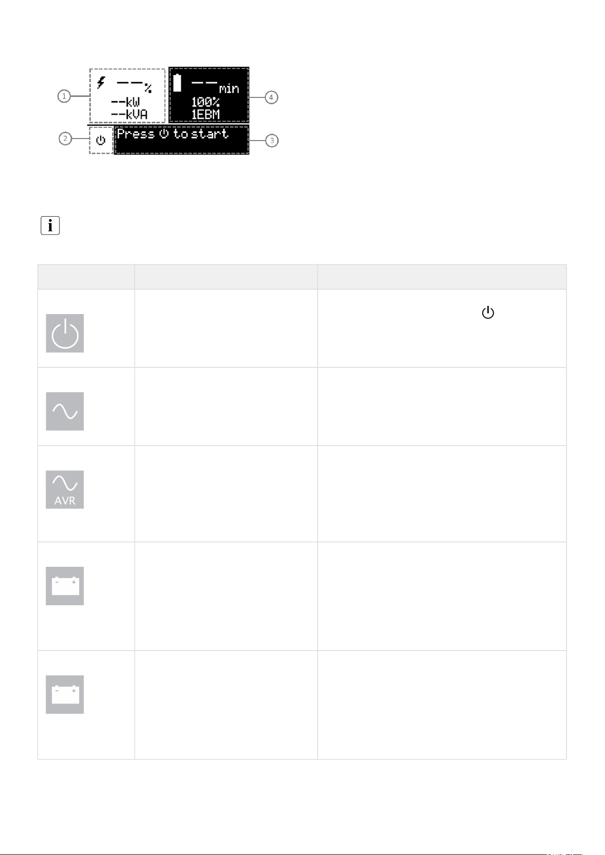
4.2 LCD description
① Load status and measurements
② Equipment status icon
③ Status / Message
④Battery status
As default, or after 5 minutes of inactivity, the LCD displays the screen saver.
The backlight LCD automatically dims after 5 minutes of inactivity. Press any button to restore the screen.
Note. If other indicator appears, see troubleshooting page for additional information.
The following table describes the status information provided by the UPS :
Operation status Possible cause Action
Standby mode
The UPS is OFF, waiting for start-up
command from user
Equipment is not power until button is pressed
during start up and the green "normal mode" LED
indicator is illuminated.
Normal mode
The UPS is operating normally.
The UPS is powering and protecting the equipment.
In AVR mode
No beep
The UPS is operating normally but the
utility voltage is outside Normal mode
thresholds.
The UPS is powering the equipment through the
Automatic Voltage Regulation device. The equipment is
still normally protected.
On Battery
One beep every 10
seconds
A utility failure has occurred and the
UPS is in Battery mode.
The UPS is powering the equipment with battery
power. Prepare your equipment for shutdown.
End of backup time
1 beep every 3
seconds
The UPS is in Battery mode and the
battery is running low.
This warning is approximate, and the actual time to
shutdown may vary significantly. Depending on the
UPS Load, the "Battery Low" warning may occur before
the battery reaches 20% capacity remaining.

614-40095-00
19
4.3 Display functions
Press the Enter (⮠) button to activate the menu options. Use the two middle buttons (⯅ and ⯆) to scrollthrough the
menu structure. Press the Enter (⮠) button to select an option. Press the (ESC) button to cancelor return to the previous
menu.
Menu map for display functions
Main menu Submenu Display information or Menu function
Measurements -
Load: [Total Load/Load (Primary)/Load (Group 1)/Load (Group 2)] : W, A, VA, pF
[Input/Output] : V, f
[Efficiency] : %
[Battery Info] : %, min, V, number of EBM, Age service, Age Warning
[Average power usage] : Toal, Primary, Group 1, Group 2
[Cumulative power] : Total, Since Primary, Since Group 1, Since Group 2
Control
Load Segments
Group 1: ON / OFF
Group 2: ON / OFF
These commands overrule user settings for load segments.
Start battery test Starts a manual battery test (possible if load >20% and battery >80%)
Change battery Disable charger, Replace battery, Update settings
Connectivity test
Dry contacts test, Relay card test, Line failure test, Battery low test
Functions reset
Reset fault state, Reset power usage, Reset battery life, Card reset, Restore
factory settings
Settings
Local settings Sets product general parameters, see User settings
Input / output
settings
Sets input and output parameters
ON / OFF settings Sets ON / OFF conditions
Battery settings Sets battery configuration
Communication
settings
Sets communication parameters (input/output signals, remote signals, IPV4
address)
Event log
View alarms
Displays the alarms stored
View events Displays the events stored
View all Displays the faults and events stored
Reset all Clears the faults and events stored
Fault log
View fault Displays the faults stored
Reset faults Clears faults

614-40095-00
20
Main menu Submenu Display information or Menu function
Identification
Type / Model / Part Number / Serial Number / UPS Firmware / NMC Firmware /
IPV4 Address / IPV6 Address / Com card MAC Address
Registration Links to Eaton registration website

614-40095-00
21
4.4 User settings
The following table displays the options that can be changed by the user.
Submenu Available settings Default settings
Local
settings
Language
[English] [Français] [Deutsch] [Español] [Русский]
[Português] [Italiano] [Simplified Chinese] [Japanese]
Menus, status, notices and alarms, UPS fault, Event Log
data and settings are in all supported languages.
English
Automatic message for user
configuration when UPS is
powered for the first time.
Date / time
Format: [International] [US] [US]
LCD
Modify LCD screen brightness and contrast to be adapted
to room light conditions.
[0]
Audible
alarm
[Enabled] [Disabled on battery] [Always disabled]
Enable or disable the buzzer if an alarm occurs.
[Enabled]
Level: [0-8] [6]
Protected
access
[Enabled] [Disabled]
Allow the user to lock the settings modification. Password
is: 0577
[Disabled]
In/Out
settings
Output
voltage
[100 V] [110 V] [120 V] [125 V] [120 V]
Input
thresholds
[Normal] [Extended]
Extended mode authorises lower input voltage(70V)witho
ut transferring to battery.
This can be used if the load can withstand low voltage
supply.
[Normal]
Sensitivity
[High] [Low]
Low sensitivity extend the range of input frequency
accepted before transferring to battery.
[High]
Load
segments
[Auto start delay]
UPS:[No delay]; Group1:[3s];
Group2:[6s]
[Auto shutdown delay]
UPS:[Disabled]; Group1:
[Disabled]; Group2:[Disabled]
Overload
prealarm
[10%] … [105%]
Load % when overload alarm occurs
[105%]
ON/OFF
settings
Start/Restart
[Cold start]
[Auto restart]
[Auto start]
[Cold start] : ON
[Auto restart] : ON
[Auto start] : OFF

614-40095-00
22
Submenu Available settings Default settings
Forced
reboot
[Yes] [No]
[Timer] [10s] … [180s]
When mains recovers during a shutdown sequence:
If set to Enabled, shutdown sequence will complete and
wait 10 seconds prior to restart,
If set to Disabled, shutdown sequence will not complete,
UPS stays on.
[Yes]
[10s]
Energy saving
(W,%, delay)
[Yes] [No]
[Time] [1min] … [15min]
[Level] [10W] … [1000W-3000W]
If Enabled, UPS will shut-down after defined duration of
back-up time, if load is less than set value.
[No]
[5min]
[100W]
Sleep Mode +
timer
[Enabled] [Disabled]
[Timer] [10min] … [120min]
If Disabled, LCD and communication will turn OFF
immediately after UPS is OFF.
If Enabled, LCD and communication stays ON for the set
time period after UPS is OFF (default 90 min).
[Enabled]
[90min]
Site Wiring
Fault
[Enabled] [Disabled]
Prevents the UPS from starting if the phase and neutral
wires are swapped..
[Enebled]
Power Off
alert
[Yes] [No]
If enabled, activates a confirmation screen that requires
user confirmation after pressing the power button, before
UPS shutdown occurs.
[Yes]
Battery
settings
Auto battery
test
In ABM® cycling mode: [No test] [Every ABM® cycle]
In constant charge mode: [No test] [Daily] [Weekly]
[Monthly]
[Every ABM® cycle]
[Weekly]
Battery life
warning
[Enabled] [Disabled]
[6-120]
Battery Age warning
If Enabled, the UPS displays a battery replacement
reminder through the front LCD and any installed network
communication card after the indicated timeframe has
elapsed (default 48 months).
[Enable]
[48 Month]
Low battery
warning
(capacity +
remain. time)
[Capacity] [0%] … [100%]
[Runtime] [0min] … [60min]
The alarm triggers when the set percentage of battery
capacity or remaining back-up time is reached.
[0%]
[3min]

614-40095-00
23
Submenu Available settings Default settings
Restart batt.
level
[0%] ... [100%]
Automatic restart will occur only when the set percentage
of battery charge is reached, and "Auto Restart" is enabled
and set to ON. A setting of 0% allows immediate automatic
restart when utility returns after a UPS shutdown due to
an extended power outage.
[0%]
Battery
charge mode
[ABM® cycling] [Constant charge] [ABM® cycling]
External
battery
[Auto detection] [Manual EBM set.] [Manual battery set.]
[Auto detection]
Using standard EBM, UPS
automatically detects the
number of EBM connected
Deep disch.
protect.
[Enabled] [Disabled]
If set to Enable, the UPS operates within the normal design
range of the battery during discharge.
If set to Disable, the UPS allows deeper battery discharge
to extend battery runtime at the expense of long-term
battery life (warranty is also void if set to disable).
[Enable]
Comm
settings
Input signals
[ROO] [RPO] [DB9-4]
Sets Input signals parameters (function, delay, operation)
through external contact connectors or RS232 port.
ROO port:
- [Function]: [No] [ROO] [RPO] [Building alarm][Shutdown
commands]
- [Delay]: [0s] … [999s]
- [Active]: [Open] [Closed]
RPO port:
- [Function]: [No] [ROO] [RPO] [Building alarm][Shutdown
commands]
- [Delay]: [0s] … [999s]
- [Active]: [Open] [Closed]
DB9-4 port:
- [Function]: [No] [ROO] [RPO] [Building alarm][Shutdown
Commands]
- [Delay]: [0s] … [999s]
- [Active]: [Low] [High]:
[No]
[0s]
[Closed]
[No]
[0s]
[Open]
[No]
[0s]
[High]
Outputs
signals
[Relay] [DB9-1] [DB9-7] [DB9-8]
Sets events or fault that will actuate Output signal
parameters through external contact connector or RS232
port
[Relay]: [On bat] [Low bat] [Bat fault] [UPS OK] [Load
protected] [Load powered] [General alarm] [OVL pre-
alarm]
[DB9-1]: [On bat] [Low bat] [Bat fault] [UPS OK] [Load
protected] [Load powered] [General alarm] [OVL pre-
alarm]
[Relay] : [Bat fault]
[DB9-1] : [Low bat]
[DB9-7] : [UPS OK]
[DB9-8] : [On bat]

614-40095-00
24
Submenu Available settings Default settings
[DB9-7]: [On bat] [Low bat] [Bat fault] [UPS OK] [Load
protected] [Load powered] [General alarm] [OVL pre-
alarm]
[DB9-8]: [On bat] [Low bat] [Bat fault] [UPS OK] [Load
protected] [Load powered] [General alarm] [OVL pre-
alarm]
Remote
command
[Yes] [No]
If Enabled, shutdown or restart commands from software
are authorized.
[Yes]
Shutdown
commands
[Send CMD] [Output OFF] [OFF delay] [restart]
Sets events or fault that will actuate Output signal
parameters through external contact connector or RS232
port
[Send CMD]: [Yes] [No]
[Output OFF]: [No] [UPS] [Group 1]
[Group 2] [Group 1 + 2]
[OFF delay]: [0s] …[999s]
[Restart]: [Yes] [No]
For a proper server shutdown please make sure that the
Output OFF delay is long enough
Send CMD: [No]
Output OFF: [No]
OFF delay: [0s]
Restart: [Yes]
On battery
notice delay
[0s] ... [99s]
Sets delay before providing an on battery notice to
software.
[0s]
General
alarm
[On battery] [Battery fault] [Overload pre-alarm] [Internal
fault] [Ambient temp.] [Fan lock] [Current limit] [Short
circuit] [Inverter overload] [Power overload] [Low battery]
[UPS OK] [Load protected] [Load powered]
Defines which event or fault will generate a general alarm
through Output signal screen.
[Internal fault]
Set Comm
Card IPv4
[DHCP] : [Yes] [No]
[IP Adress] [Subnet mask] [Gateway]
The UPS does not display the IPv4 settings menu by
default, you can activate it by a communication
command.
[Yes]
XXX.XXX.XXX.XXX
4.5 Communication ports
614-40095-00
25
1.
2.
•
•
•
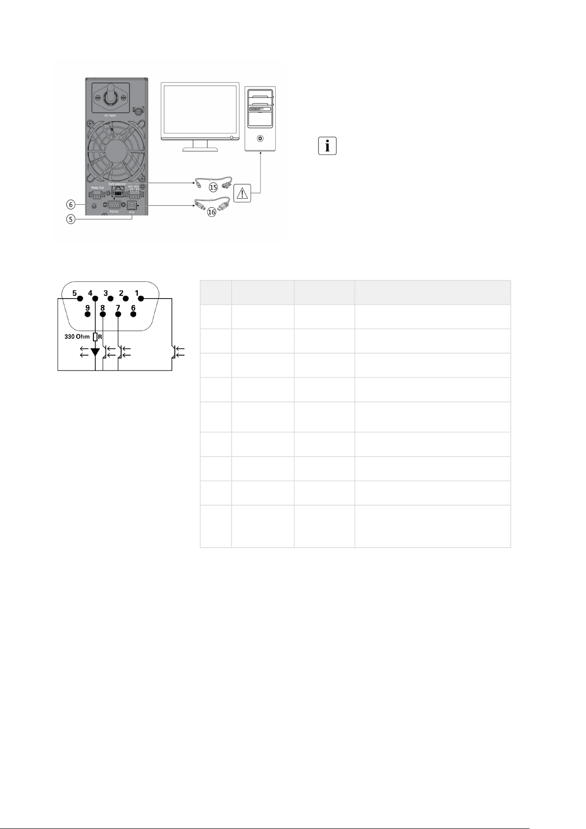
Connection of RS232/USB communication port
Connect the RS232 (15) or USB (16) communication
cable to the serial or USB port on the computer
equipment.
Connect the other end of the communication cable
(15) or (16) to the USB (5) or RS232 (6)
communication port on the UPS.
The UPS can now communicate with Eatonpower
management software.
You can improve the remote monitoring and power
managment of the UPS by adding acommunication
cardcompatible with the 5PXproduct.
Characteristics of the contact RS232 communication port
Contact characteristics
(optocoupler)
Voltage: 48 V DC max
Current: 25 mA max
Power: 1.2 W
Pin Signal Direction Function
1 Bat low Output Low Battery Output
2 TxD Output Transmit to external device
3 RxD Input Receive from external device
4 I/P SIG Input -
5 GNDS -
Signal Common tied to chassis
6 PNP Input Plug and Play
7 UPS OK Output UPS OK
8 BAT mode Output UPS on battery mode
9 +5V Output
Power supply for external
signal or options
614-40095-00
26
1.
2.
3.
•
•
•
•
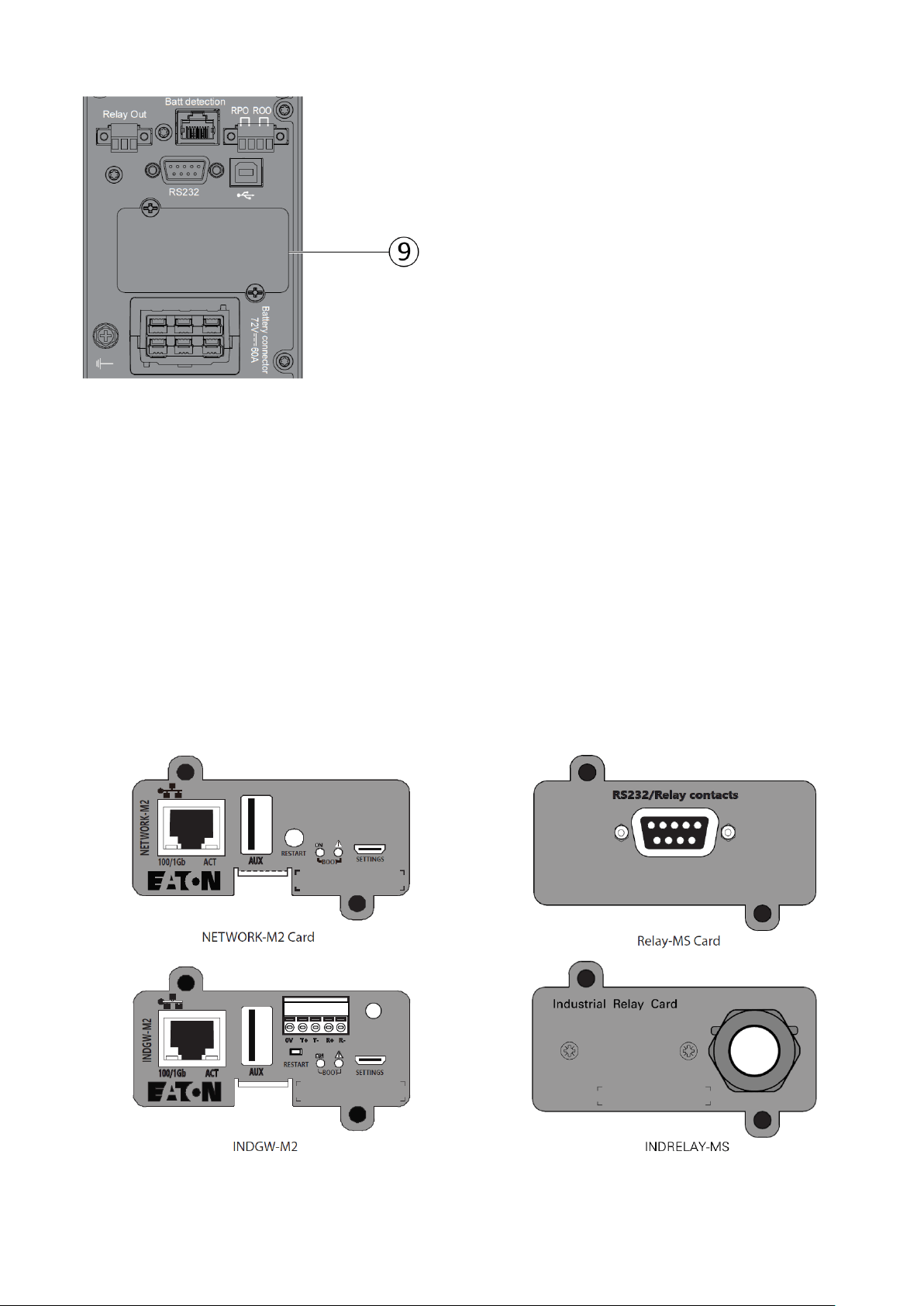
Installation of the communication cards
It is not necessary to shutdownthe UPS before
installinga communication card.
Remove the slot cover (9)secured by screws.
Insert the communicationcard in the slot.
Secure the card cover withthe two screws to
connect the comm card to the ground.
4.6 UPS remote control functions
Connectivity cards
Connectivity cards allow the UPS to communicate in a variety of networking environments and with differenttypes of
devices. The5PXmodels have one available communication bay for the following connectivity cards:
Gigabit Network card(Network-M2) : provides a Gigabit Ethernet connection and enables secure UPS monitoring
over HTTPS web browser interface, SNMP v1/v3 protocol and email alarms. In addition, up to 3 Environmental
Monitoring Probes can be attached to obtain humidity, temperature, smoke alarm, and security information.
Industrial Gateway card(INDGW-M2) :Provides Modbus RTU and Modbus TCP communication support in addition
to the same secure UPS monitoring, management and sensor capability as the Gigabit Network card.
Relay-MS card: provides isolated dry contact (Form-C) relay outputs for UPS status: Utility failure, Battery low, UPS
alarm/OK, or on Bypass.
INDRELAY-MS : The Industrial relay Card-MS (INDRELAY-MS) provides a simple way to remotely input UPS information
to an alarm system, PLC or a computer system via dry contacts. It offers five isolated dry contact outputs and one
isolated dry contact input.
614-40095-00
27
•
•
•
•
•
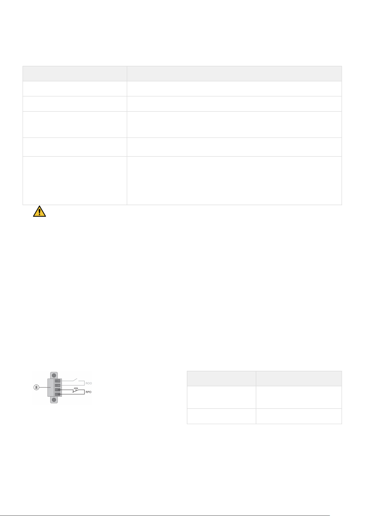
Programmable signal inputs
The 5PX incorporates several programmable signal inputs: oneRemote Power Off (RPO) input terminal, one RemoteOn/
Off (ROO) input terminal, one RS-232 input (pin-4).
Signalinputs can be configured (see Settings > Comm settings > Signal Input) to have one of the following functions:
Function Description
No No function. (Please choose a function if you want to use input signal.)
RPO Remote Power off (RPO) is used to shutdown the UPS remotely.
ROO
Remote On/Off allows remote action of a button or other interface to switch On/
Off the UPS. (Cold start is prohibited while using the ROO function.)
Building alarm
Active input generates an alarm “building alarm”.
Shutdown commands
Active input turns UPS output (or outlet groups) off after a user defined
shutdown delay but keeps on charging batteries according to a selected charging
scheme; inactive input does not abort shutdown countdown. Depending on the
“Restart” parameter (see Settings > Comm Settings > Shutdown commands) the
unit may startup automatically.
Warning: signal inputs have no function by default; please choose a function through the LCD(Settings > Com
settings > Input signals).
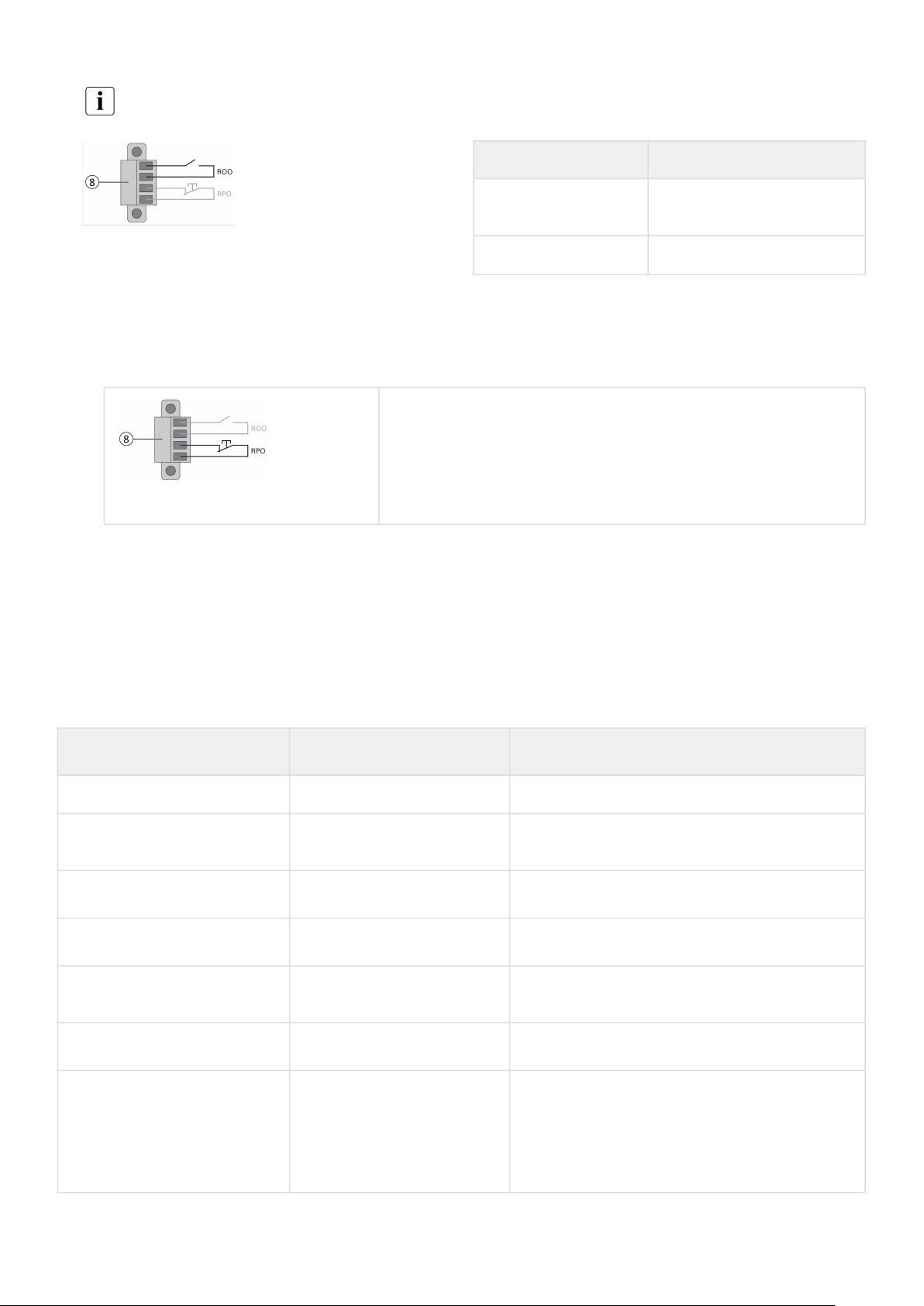
See below 2 examples of configuration with RPO terminal used as RPO function and ROO terminal use asROO function:
Remote Power Off (RPO)
RPO is used to shutdown the UPS remotely when the contact is open. This feature can be used for shuttingdown the load
and the UPS by thermal relay, for example, in the event of room over temperature. When RPO is activated, the UPS turns
off the output and shuts down all power converters immediately (except for logic power).The UPS remains "ON" to alarm
the fault.
The RPO circuit is an IEC 60950 safety extra low voltage (SELV) circuit. This circuit must be separated from anyhazardous
voltage circuits by reinforced insulation.
The RPO must not be connected to any utility connected circuits. Reinforced insulation to the utility is required. The
RPO switch must be a dedicated latching-type switch not tied into any other circuit. The RPO signal must remain
active for at least 250 ms for proper operation.
To ensure the UPS stops supplying power to the load during any mode of operation, the input power must be
disconnected from the UPS when the Remote Power Off function is activated.
RPO connections:
RPO Comments
Connector type
Terminal, 14 AWG Maximum
wires
Terminal rating 60 V DC/30 V AC 20 mA max
Remote On/Off (ROO)
Remote On/Off allows remote action of button to switch On/Off the UPS.
When contact changes from open to closed, the UPS is switched-on (or stays On).
When contact changes from closed to open, the UPS is switched-off (or stays Off).
614-40095-00
28
•
1.
2.
3.
4.
5.
6.
On/Off control via button has priority over the remote control.
The ROO function is only active after the first use of the "Remote OFF" function.
ROO Comments
Connector type
Terminal, 14 AWG Maximum
wires
Terminal rating 60 V DC/30 V AC 20 mA max
Remote control connection and test
Check the UPS is shut down and the electrical supply network disconnected.
Remove RPO connector from the UPS by removing the screws.
Connect a normally closed volt-free contact between the two pins of connector.
Normally closed
Contact open: shut down of UPS.
To return to normal operation, deactivate the external remote shut
down contactand restart the UPS from the front panel.
Plug the RPO connector into the back of the UPS and fix the screws.
Connect and restart the UPS according to the previously described procedures.
Activate the external remote shut down contact to test the function.
Always test the RPO function before applying your critical load to avoid accidental load loss.
Programmable signal outputs
The5PX incorporates several programmable signal outputs: one relay output and two optocoupler outputs (DB9 pins 1
and 8).Signal outputs can be configured (see Settings > Comm settings > Output Signals) to report thefollowing
information:
Signal
Default assignment
Description
On battery (On Bat) DB9-Pin 8 UPS is in battery mode
Low battery (Low Bat) DB9-Pin 1
UPS is in battery mode and has reached the low
battery alarm threshold
Battery fault
(1) Relay output
Battery fault
UPS OK DB9-Pin 7
Load is powered with no alarm
Load protected -
UPS is on inverter, with no alarm and ready to go to
battery
Load powered -
Load is powered
General alarm -
Choose events that will trigger this alarm trough
the LCD (Settings > Comm settings > General
alarm).
For more information on possible events please
look at User settings
614-40095-00
29
Signal
Default assignment
Description
OVL pre-alarm - Overload pre-alarm
Bat disconn - Battery is disconnected
(1) Relay output:
4.7 Eaton Intelligent Power Software suite
Eaton Intelligent Power Software suite is available from eaton.com/downloads.
Eaton Software suite provides up-to-date graphics of UPS power and system data and power flow.
It also gives you a complete record of critical power events, and it notifies you of important UPS or powerinformation.
If there is a power outage and the 5PX UPS battery power becomes low, Eaton Software suite can automaticallyshut
down your computer system to protect your data before the UPS shutdown occurs.
4.8 Cybersecurity
Eaton is committed to minimizing the Cybersecurity risk in its products and employs cybersecurity bestpractices and the
latest cybersecurity technologies in its products and solutions, making them more secure,reliable and competitive for
our customers. Eaton also offers Cybersecurity Best Practices whitepapers to itscustomers, referenced at
www.eaton.com/cybersecurity.
5 Operation
5.1 Start-up and normal operation
Check that the indications on the name plate located on the back of the UPS meets to the AC power source and the
true electrical consumption of the total load.
Battery charge
The UPS charges the battery as soon as it is connected to the AC outlet, whether the ON/OFF button is pressedor not. It is
recommended that the UPS be permanently connected to the AC power supply toensure the best possible autonomy.
On the first startup of the UPS, you will need to configure the output voltage and time of the UPS.
To start the UPS:
1. Verify that the UPS power cord is plugged in.
2. The UPS front panel display illuminates and shows Eaton logo.
3. Verify that the UPS status screen shows .
4. Press the button on the UPS front panel for at least two seconds.
5. Check the UPS front panel display for active alarms or notices. Resolve any active alarms before continuing; if the
indicator is on, do not proceed until all alarms are clear (see "Troubleshooting" section). Check the UPS status from the
front panel to view the active alarms. Correct the alarms and restart if necessary.
6. Verify that the indicator illuminates solid, indicating that the UPS is operating normally and any loads are powered
and protected. The UPS should be in Normal mode.

614-40095-00
30
1.
2.
•
•
AC-power disturbance
If AC power is disturbed or fails, the UPS continues to operate on battery power. In normal mode, the audio alarm beeps
every ten seconds, then every three seconds when the end ofbattery backup time is near.
If the power outage lasts longer than the battery backup time, the UPS shuts down and automatically restartswhen
power is restored. Following a complete discharge, at least 48 hours are recommended to recharge the battery backto
full backup time.
To extended battery runtime for critical devices, it is possible to program sequenced shutdown (also known as load
shedding) of less-critical loads connected to Group 1 or Group 2 outlets during extended power outages.
5.2 Starting the UPS on battery
Before using this feature, the UPS must have been powered by utility power with output enabled at leastonce.
Battery start can be disabled. See the "Cold start" setting in "ON/OFF Settings".
To start the UPS on battery:
When the UPS is disconnected from the AC power source, press the button on the UPS front panel.
The UPS transfers from Standby mode to Battery mode. The indicator illuminates solid.
The UPS supplies power to your equipment.
Check the UPS front panel display for active alarms or notices besides the "Battery mode" and related notifications
that indicates missing utility power. Resolve any active alarms before continuing. See "Troubleshooting".
Check the UPS status from the front panel to view the active alarms. Correct the alarms and restartif necessary.
5.3 UPS shutdown
To shut down the UPS:
Press the button on the front panel for three seconds.
A confirmation message will appear. When confirmed, the UPS starts to beep and shows a status of "UPS shutting OFF...".
The UPS thentransfers to Standby mode, and the indicator turns off.
5.4 Operating modes
The Eaton5PX front panel indicates the UPS status through the UPS indicators located above the LCD screen.
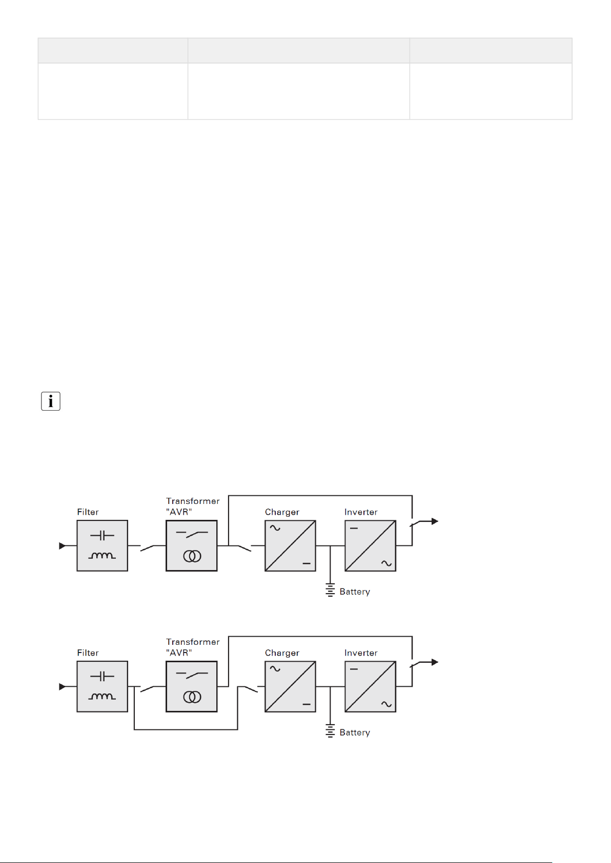
Normal mode
When the green sinewave symbol is illuminated, the UPS is providing protected AC power output.The UPS monitors and
charges the batteries as needed and providespower protection to yourequipment.
Battery mode
When the UPS is operating during a power outage, the alarm beeps once every ten seconds and theindicator illuminates
solid. The necessary energy is provided by the battery.
When the utility power returns, the UPS transfers to Normal mode operation while the battery recharges.
If battery capacity becomes low while in Battery mode, the audible alarm beeps once every three seconds.
This warning is approximate, and the actual time to shutdown may vary significantly; gracefully shutdown all applications
on connected equipment due to imminent UPS shutdown.
When utility power is restored after the UPS shuts down, the UPS automatically restarts.
Low-battery warning
The indicator illuminates solid.
The audio alarm beeps every three seconds.
The remaining battery power is low. Shut down all applications on the connected equipment becauseautomatic UPS
shutdown is imminent.

614-40095-00
31
•
•
•
1.
2.
1.
2.
End of battery backup time
LCD displays "End of backup time".
All the LEDs go OFF.
The audible alarm stops.
5.5 Return of AC input power
Following an outage, the UPS restarts automatically when AC input power returns (unless the restart functionhas been
disabled) and the load is supplied again.
5.6 Retrieving the event log
To retrieve the event log through the display:
Press any button to activate the menu options, then select event log.
Scroll through the listed events.
5.7 Retrieving the fault log
To retrieve the fault log through the display:
Press any button to activate the menu options, then select fault log.
Scroll through the listed faults.
6 UPS maintenance
6.1 Equipment care
For the best preventive maintenance, keep the area around the equipment clean and dust free. If the atmosphere is very
dusty, clean the outside of the system with a vacuum cleaner.
For full battery life, keep the equipment at an ambient temperature of 25 °C (77 °F).
The batteries are rated for a 3-5 year service life. The length of service life varies, depending on the frequency of usage
and ambient temperature (life divided by 2 each 10 °C above 25 °C).
If the UPS requires any type of transportation, verify that the UPS is turned off.
Batteries used beyond expected service life will often have severely reduced runtimes. Replace batteries at least every 4
years to keep units running at peak performance.
Batteries runtime will be reduced at low temperature (below 10 °C).
6.2 Storing the equipment
If you store the equipment for a long period, recharge the battery every 6 months by connecting the UPS toutility power.
The internal batteries charge to 90% capacity in less than 3 hours. However, Eaton recommendsthat the batteries charge
for 48 hours after long-term storage.
Check the battery recharge date on the shipping carton label. If the date has passed and the batteries were never
recharged, do not use them. Contact your servicerepresentative.
614-40095-00
32
•
•
a.
b.
c.
d.
•
•
•
•
•
•
•
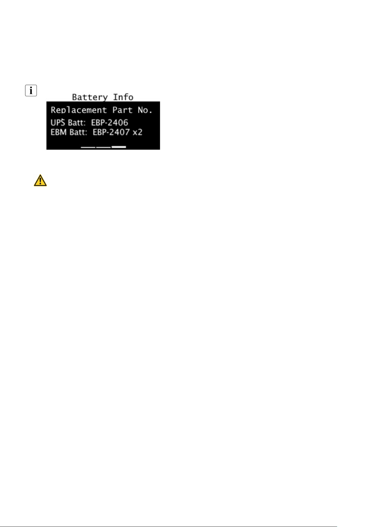
6.3 When to replace batteries
Eaton UPS batteries have an expected life span of 3-5 years.
After 4 years of operation, the UPS will provide a battery replacement notification reminding you that your batteries are
nearing the end of their useful life. You should take proactive steps to ensure you replace your batteries for optimal
operation and reliability.
Contact your service representative to order new batteries.
Battery recommended replacement date and reference can be accessed through the LCD (Measurements > Battery).
6.4 Replacing batteries
DO NOT DISCONNECT the batteries while the UPS is in Battery mode.
For battery replacement, follow Eatoninstructions provided onwww.eaton.com/UPSservices.
Batteries can be replaced easily without turning off the UPS or disconnecting the load.
Consider all warnings, cautions, and notes before replacing batteries.
Servicing should be performed by qualified service personnel knowledgeable of batteries and required precautions.
Keep unauthorized personnel away from batteries.
Batteries can present a risk of electrical shock or burn from high short circuit current.
Observe the following precautions:
Remove watches, rings, or other metal objects,
Use tools with insulated handles,
Do not lay tools or metal parts on top of batteries,
Wear rubber gloves and boots.
When replacing batteries, replace with the same type and number of batteries or battery packs. Contact your service
representative to order new batteries.
Proper disposal of batteries is required. Refer to your local codes for disposal requirements.
Never dispose of batteries in a fire. Batteries may explode when exposed to flame.
Do not open or mutilate the battery or batteries. Released electrolyte is harmful to the skin and eyes and may be
extremely toxic.
Determine if the battery is inadvertently grounded. If inadvertently grounded, remove source from ground. Contact
with any part of a grounded battery can result in electrical shock.
The likelihood of such shock can be reduced if such grounds are removed during installation and maintenance
(applicable to equipment and remote battery supplies not having a grounded supply circuit).
ELECTRIC ENERGY HAZARD. Do not attempt to alter any battery wiring or connectors. Attempting to alter wiring can
cause injury.
Disconnect charging source prior to connecting or disconnecting battery terminals.
614-40095-00
33
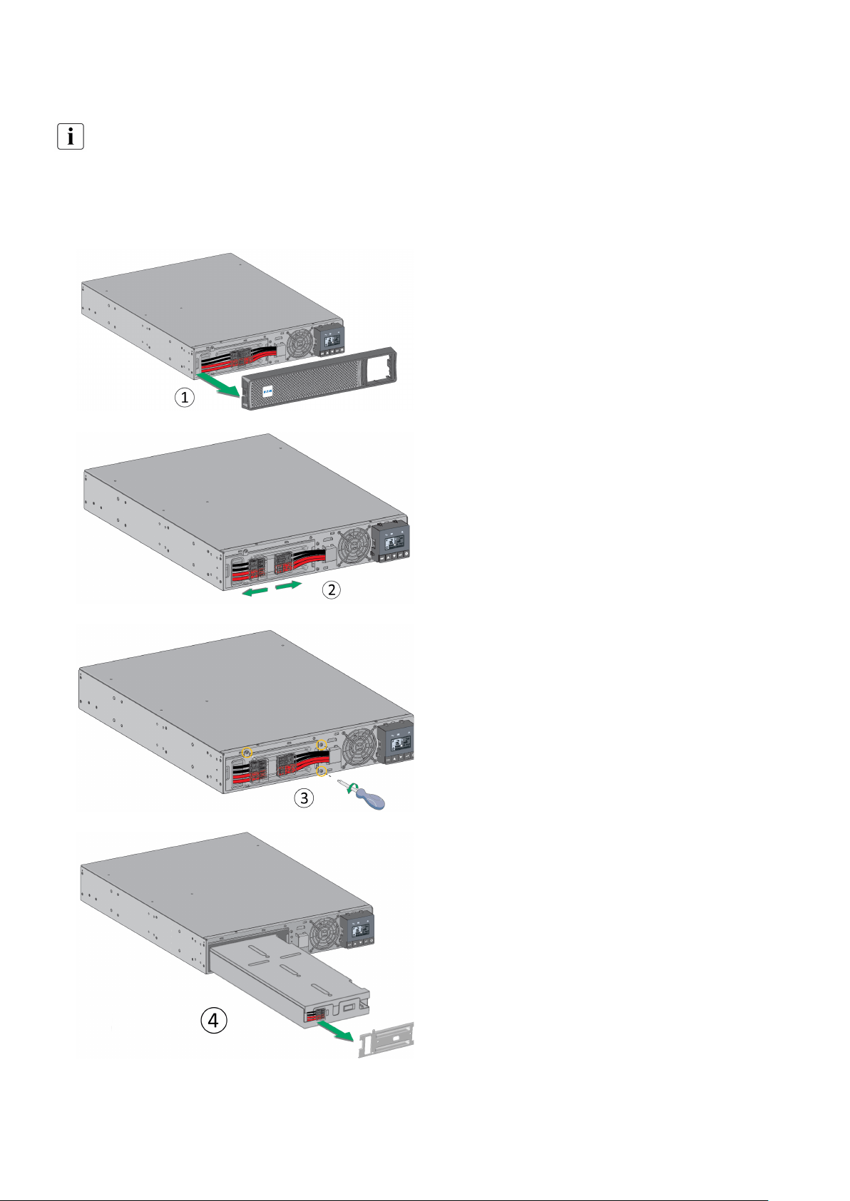
Replacing the internal battery :
The internal battery is heavy. Use caution when handling the heavy batteries.
A Phillips head screwdriver is needed to perform this procedure
1 - Pull off the front panel by pressing the tabs on both
sides.
2 - Disconnect the battery pack byseparating the
connectors(never pull on the wires).
3 - Remove the metal protection coverin front of the
battery (three screws or two screws for 3U models).
4 - Pull the plastic tab to removethe battery pack and
replace it.
614-40095-00
34
1.
2.
1.
2.
3.
Warning: take care not to reverse the polarity + (red) and - (black) when connecting the batteries as this
willdestroy the device.
6.5 Replacing the UPS equipped with a HotSwap MBP
The HotSwap MBP module makes itpossible to service
or even replacethe UPS without affecting the
connectedloads (HotSwap function).
Maintenance
Set switch (45) to Bypass position.The red LED on the
HotSwap MBPmodule goes ON, indicating that
theload is supplied directly with AC inputsource
power.
Stop the UPS by pressing the button on the UPS
control panel. LED (43) "UPS ON - OK to switch" goes
OFF, the UPS can now be disconnected and replaced.
Return to normal operation
Check that the UPS is correctly connected to the
HotSwap MBP module.
Start the UPS by pressing the button on the UPS
control panel.LED (43) "UPS ON - OK to switch"
onthe HotSwap MBP module goes ON(otherwise,
there is a connection errorbetween the HotSwap
MBP moduleand the UPS).
Set switch (45) to Normal position.The red LED on
the HotSwap MBPmodule goes OFF.
6.6 Recycling the used equipment
Contact your local recycling or hazardous waste center for information on proper disposal of the usedequipment.
eaton.com/recycling
Do not dispose of the battery or batteries in a fire. Batteries may explode. Proper disposal of batteries is required.
Refer to your local codes for disposal requirements.
Do not open or mutilate the battery or batteries. Released electrolyte is harmful to the skin and eyes. It may be
toxic.
Do not discard the UPS or the UPS batteries in the trash. This product contains sealed, lead acid batteries andmust
be disposed of properly. For more information, contact your local recycling/reuse or hazardous wastecenter.
Do not discard waste electrical or electronic equipment (WEEE) in the trash. For proper disposal, contact yourlocal
recycling/reuse or hazardous waste center.
7 Troubleshooting
TheEaton5PXis designed for reliable, autonomous operation while providing you with notifications and alerts whenever
a potential operational or performance issue occurs.
Usually the alarms shown by the control panel do not mean that the output power is affected. Instead, they are
preventive alarms intended to alert the user.

614-40095-00
35
•
•
•
1.
2.
3.
Events are silent status information that are recorded into the Event log. Example = "AC freq in range".
Alarms are recorded into the Event log and displayed on the LCD status screen with the logo blinking. Some alarms
may be announced by a beep every 3 seconds. Example = "Battery low".
Faults are announced by a continuous beep and red LED, recorded into the Fault log and displayed on the LCD with a
specific message box. Example = Out. short circuit.
Use the following troubleshooting chart to determine the UPS alarm condition.
7.1 Typical alarms and faults
To check the Event log or Fault log:
Press any button on the front panel display to activate the menu options.
Press the down button to select Event log or Fault log.
Scroll through the listed events or faults.

614-40095-00
36
The following table describes typical conditions:
Conditions Possible cause Action
Battery mode
LED is On.
1 beep every 10 seconds
A utility failure has occurred and the UPS is in
battery mode.
The UPS is powering the
equipment with battery power.
Prepare your equipment for
shutdown.
Battery mode
LED is On.
1 beep every 3 seconds
The UPS is in Battery mode and the battery is
running low.
This warning is approximate, and
the actual time to shutdown may
vary significantly. Depending on
the UPS load and number of
Extended Battery Modules (EBMs),
the "Battery Low" warning may
occur before the batteries reach
20% capacity.
No battery
LED is On
Beep continuous
The batteries are disconnected.
Verify that all batteries are
properly connected. If the
condition persists, contact your
service representative.
Battery mode
LED is On.
Beep continuous
The battery test is failed due to bad or
disconnected batteries.
Verify that all batteries are
properly connected. If the
condition persists, contact your
service representative.
The UPS does not provide the
expected backup time.
The batteries need charging or service.
Apply utility power for 48 hours to
charge the batteries. If the
condition persists, contact your
service representative.
Power Overload
LED is On
Power requirements exceed the UPS capacity
(greater than 100% of nominal;
see “User Settings” for specific output overload
ranges).
Remove some of the equipment
from the UPS. The UPS continues
to operate, but may shut down if
the load increases. The alarm
resets when the condition
becomes inactive.
UPS Over temperature
LED is On
1 beep every 3 seconds
The UPS internal temperature is too high or a fan
has failed. At the warning level, the UPS
generates the alarm but remains in the current
operating state. If the temperature rises another
10°C, the UPS shuts down.
Clear vents and remove any heat
sources. Allow the UPS to cool.
Ensure the airflow around the UPS
is not restricted. Restart the UPS. If
the condition continues to persist,
contact your service
representative.
The UPS does not start
The input source is not connected correctly.
Check the input and battery
connections.
614-40095-00
37
•
•
•
•
•
•
Conditions Possible cause Action
The Remote Power Off (RPO) switch is active or
the RPO connector is missing.
If the UPS Status menu displays
the "Remote Power Off" notice,
deactivate the RPO input.
7.2 Silencing the alarm
Press the ESC (Escape) button on the front panel display to silence the alarm. Check the alarm condition andperform the
applicable action to resolve the condition. If the alarm status changes, the alarm beeps again,overriding the previous
alarm silencing.
7.3 Service and support
If you have any question or problem with the UPS, call Eaton or your local service representative in your country / region.
Please have the following information ready when you call for service:
Model number
Serial number
Firmware version number
Date of failure or problem
Symptoms of failure or problem
Customer return address and contact information
If repair is required, you will be given a Returned Material Authorization (RMA) number. This number must appear on the
outside of the package and on the Bill Of Lading (if applicable). Use the original packaging or request packaging from the
Help Desk or distributor. Units damaged in shipment as a result of improper packaging are not covered under warranty. A
replacement or repair unit will be shipped freight prepaid for all warrantied units.
For critical applications, immediate replacement may be available. Call the Help Desk for the dealer or distributor
nearest you.
For US and Canada you can contact post-sales service support at: 1-(800)-356-5737.
8 Specification and technical characteristics
5PX 1000 / 1500 models :
5PX 2000 / 3000 models :

614-40095-00
38
8.1 UPS model list
Description Catalog Number Power rating Configuration
Eaton 5PX 1000 RT2U G2
Eaton 5PX 1000 RT2U Netpack G2
5PX1000RTG2
5PX1000RTNG2
1000W/1000VA Rack / Tower
Eaton 5PX 1500 RT2U G2
Eaton 5PX 1500 RT2U Netpack G2
5PX1500RTG2
5PX1500RTNG2
1440W/1440VA Rack / Tower
Eaton 5PX 2200 RT2U G2
Eaton 5PX 2000 RT2U Netpack G2
5PX2000RTG2
5PX2000RTNG2
1950W/1950VA Rack / Tower
Eaton 5PX 2000 RT3U Netpack Short
G2
5PX2000RT3UNG2 1950W/1950VA Rack / Tower
Eaton 5PX 3000 RT2U G2
Eaton 5PX 3000 RT2U Netpack G2
5PX3000RTG2
5PX3000RTNG2
3000W/3000VA Rack / Tower
Eaton 5PX 3000 RT3U Netpack Short
G2
5PX3000RT3UNG2 3000W/3000VA Rack / Tower
8.2 Extended Battery Module model list
Model
Catalog
Number
Configura
tion
Battery
voltage
Use with
Eaton 5PX EBM 48V
RT2U G2
5PXEBM48RTG2
Rack /
Tower
48Vdc
5PX1000RTG2, 5PX1000RTNG2, 5PX1500RTG2,
5PX1500RTNG2
Eaton 5PX EBM 72V
RT2U G2
5PXEBM72RTG2
Rack /
Tower
72Vdc
5PX2000RTG2, 5PX2000RTNG2, 5PX3000RTG2,
5PX3000RTNG2
Eaton 5PX EBM 72V
RT3U G2
5PXEBM72RT3
UAG2
Rack /
Tower
72Vdc 5PX2000RT3UNG2, 5PX3000RT3UNG2
Weights and dimensions
Description (UPS) Weights (lb / kg)
Dimentions (inch / mm) D x W x H
5PX1000RTG2
5PX1000RTNG2
44.5 / 20.2 17.6x17.2x3.4 / 448x438x85.5
5PX1500RTG2
5PX1500RTNG2
50.7 / 23.0 17.6x17.2x3.4 / 448x438x85.5
5PX2000RTG2
5PX2000RTNG2
65.3 / 29.6 23.7x17.2x3.4 / 603x438x85.5
5PX2000RT3UNG2 64.2 / 29.1 19x17.2x5.1 / 483x438x129
5PX3000RTG2
5PX3000RTNG2
74.5 / 33.8 23.7x17.2x3.4 / 603x438x85.5
5PX3000RT3UNG2 72.8 / 33.0 19x17.2x5.1 / 483x438x129

614-40095-00
39
Description (EBM) Weights (lb / kg) Dimentions (inch / mm) D x W x H
5PXEBM48RTG2 61.3 / 27.8 17.6x17.2x3.4 / 448x438x85.5
5PXEBM72RTG2 89.1 / 40.4 23.7x17.2x3.4 / 603x438x85.5
5PXEBM72RT3UAG2 87.5 / 39.7 19x17.2x5.1 / 483x438x129
8.3 Electrical input
Default frequency 60Hz
Nominal frequency 50/60Hz
Frequency range 47-70Hz
Catalog Number
Default input
(Voltage/Current)
Input nominal voltages Input voltage window
5PX1000RTG2
5PX1000RTNG2
120V/12A
100-125V
80-151V
adjustable to 70-153V
5PX1500RTG2
5PX1500RTNG2
120V/12A
5PX2000RTG2
5PX2000RTNG2
120V/16A
5PX2000RT3UNG2 120V/16A
5PX3000RTG2
5PX3000RTNG2
120V/24A
5PX3000RT3UNG2 120V/24A
8.4 Electrical input connections
Catalog Number Input connection Input cable
5PX1000RTG2
5PX1000RTNG2
Fixed
NEMA 5-15P
5PX1500RTG2
5PX1500RTNG2
NEMA 5-15P
5PX2000RTG2
5PX2000RTNG2
NEMA 5-20P
5PX2000RT3UNG2 NEMA 5-20P
5PX3000RTG2
5PX3000RTNG2
NEMA 5-30P
5PX3000RT3UNG2 NEMA 5-30P

614-40095-00
40
8.5 Electrical output
All models Normal mode Battery mode
Voltage regulation
Boost : Vin*1.15
Buck : Vin*0.87
(-10% ,6%)
Efficiency >96%
1000-2200 > 82%
3000 > 85%
Frequency regulation +/-0.1 Hz
Nominal output
100/110/120/125V
Frequency Follows input frequency 50/60Hz
Output overload
[105%,120%] 30min
[120%,150%]5min
>150% 10S
[105% ~110%] 10s
[110%~150%]1s,
>150% 0.15s
Short circuit current limitationin battery
mode
Model
Current
limitation
1000 41A
1500 56A
2000 66A
3000 90A
Transfer time
Utility Outage: 1-4ms for normal mode, >5ms for sensitive mode
Utility abnormal: <10ms for normal mode ,<25ms for sensitive mode
8.6 Electrical output connection
Catalog Number
Output conection
5PX1000RTG2
5PX1000RTNG2
(4) 5-15R Primary
(2) 5-15R Group1
(2) 5-15R Group2
5PX1500RTG2
5PX1500RTNG2
5PX2000RTG2
5PX2000RTNG2
5PX2000RT3UNG2
(2)5-20R + (1)L5-20R Primary
(2) 5-20R Group1
(2) 5-20R Group2
5PX3000RTG2
5PX3000RTNG2

614-40095-00
41
Catalog Number
Output conection
5PX3000RT3UNG2
8.7 Battery
Internal batteries Internal batteries EBM
Specifications
1000VA: 48Vdc - 4 x 12V, 7Ah
1500VA: 48Vdc - 4 x 12V, 9Ah
2000VA: 72Vdc - 6 x 12V, 7Ah
3000VA: 72Vdc - 6 x 12V, 9Ah
5PXEBM48RTG2: 48Vdc - 2 x 4 x 12V, 9Ah
5PXEBM72RTG2: 72Vdc - 2 x 6 x 12V, 9Ah
5PXEBM72RT3UAG2: 72Vdc - 2 x 6 x 12V, 9Ah
Type
Sealed, maintenance-free, valve-regulated, lead-acid, with minimum 3-5 year float service life at
25°C (77°F).
Monitoring Advanced monitoring for earlier failure detection and warning
EBM battery cable
length
2U EBM cable length:350mm/13.78in
3U EBM cable length:530mm/20.87in
8.8 Environmental and safety
Standards
IEC/EN 62040-1:2008+A1:2013
EN IEC 62040-2: 2018
IEC 62040-2: 2016
FCC CFR Title 47, Part 15, Subpart B
IEC/EN 62040-3
IEC 62040-1:2017
UL1778 5th edition
CSA 22.2
EMC (Emissions)
EN IEC 62040-2: 2018 C1
EN 62040-2: 2006 C1
IEC 62040-2: 2016 C1
EN 55011:Class B
CISPR11 Class B
CISPR32 Class B
FCC part 15 Class B
EMC (Immunity)
IEC 61000-4-2, (ESD): 8 kV Contact Discharge / 15 kV Air Discharge
IEC 61000-4-3, (Radiated field): 10 V/m
IEC 61000-4-4, (EFT): 4 kV
IEC 61000-4-5, (Surges): 2 kV Differentiel Mode / 4 kV Common Mode
IEC 61000-4-6, (Electromagnetic field): 10 V
IEC 61000-4-8, (Conducted magnetic field): 30 A/m
C62.41 category B, Combo surge, Ring wave:6 kV
Agency markings
CE, cULus, FCC, Energy star, NOM,
UKCA (only on 5PX1500RTG2, 5PX1500RTNG2)
BSMI (only for 5PX1000RTG2, 5PX1500RTG2, 5PX3000RTG2)
Operating temperature 0 to 40 °C (32 to 104 °F)

614-40095-00
42
Storage temperature -15 to 50°C (5 to 122 °F)
Relative humidity 20 to 90 % (without condensation)
Operating altitude
Up to 3,000 meters (9,843 ft) above sea level, no derating for 40°c
(104°F) room temperature
Transit altitude Up to 10,000 meters (32,808 ft) above sea level
Audible noise
Line mode:<40dB Buck/boost mode:<45 dB
Batt. Mode: <45dB, 50dB for 3K
9 Glossary
AVR
The Automatic Voltage Regulationmaintains a constant voltage level for
electrical equipment loads when the voltage falls outside the voltage tolerance
range.
Backup time
Time during which the load can be supplied by the UPS operating on
batterypower.
EBM
Extended Battery Module
Low-battery warning
This is a battery-voltage level indicating that battery power is low and that the
user must take action before the UPS shuts down.
Load
Devices or equipment connected to the UPS output.
Normal mode
The normal UPS operating mode in which the AC source supplies the UPS which,
in turn, provides AC power to the connected loads.
Normal AC source
Normal source of power for the UPS.
OVL
Overload.When the load exceeds 100% of the maximum load of the UPS.
Relay contacts
Contacts supplying information to the user in the form of signals.
UPS
Uninterruptible Power System.