
2 Deutsch
Beschreibung
몇 VORSICHT
Sachschäden durch fehlerhafte Montage
Lassen Sie die Montage nur von einer dafür qualifizierten Fach-
kraft durchführen.
Aus Sicherheits- und Garantiegründen muss der Einbau durch
den Kärcher-Service vorgenommen werden.
Hinweis
Beachten Sie auch die Betriebsanleitung und die Sicherheitshin-
weise des Geräts, in das der Anbausatz eingebaut wird.
Bestimmungsgemäße Verwendung
In dieser Montageanleitung wird der Anbau des Seitenbesens
beschrieben.
Er kann an folgendes Fahrzeug angebaut werden.
● B 260 RI
Sicherheitshinweise
Gefahrenstufen
GEFAHR
● Hinweis auf eine unmittelbar drohende Gefahr, die zu schweren
Körperverletzungen oder zum Tod führt.
몇 WARNUNG
● Hinweis auf eine möglicherweise gefährliche Situation, die zu
schweren Körperverletzungen oder zum Tod führen kann.
몇 VORSICHT
● Hinweis auf eine möglicherweise gefährliche Situation, die zu
leichten Verletzungen führen kann.
ACHTUNG
● Hinweis auf eine möglicherweise gefährliche Situation, die zu
Sachschäden führen kann.
Sicherheitshinweise
ACHTUNG
Beschädigungsgefahr durch unsachgemäßen Einbau.
Bei unsachgemäßem Einbau bzw. Anschließen des Anbaugeräts
kann es zu Beschädigungen am Anbaugerät sowie am Fahrzeug
bzw. der Maschine kommen. Am Anbaugerät und Fahrzeug bzw.
Maschine können Fehlfunktionen und Ausfälle eintreten.
Lassen Sie Montage, Einbau und Anschluss des Anbaugeräts
nur von einer dafür qualifizierten Fachkraft durchführen.
ACHTUNG
Beschädigungsgefahr durch elektrostatische Entladung
(ESD)!
Elektrostatische Entladung (electrostatic discharge, ESD) kann
elektronische Bauteile beschädigen.
Ergreifen Sie vor Arbeiten an der Elektronik und Elektrik geeigne-
te Maßnahmen zur Ableitung elektrostatischer Aufladung.
ACHTUNG
Beschädigungsgefahr durch scharfkantige Gegenstände
und Verschmutzungen!
Scharfkantige bzw. verschmutzte Gegenstände können beim
Kontakt mit Bauteilen Beschädigungen wie Kratzer, Kerben und
Verformungen verursachen. Verschmutzte Werkzeuge, Lappen
und Arbeitsflächen können irreversible Verschmutzungen und
Farbveränderungen verursachen.
Verwenden Sie ausschließlich geeignete, unbeschädigte und
saubere Werkzeuge und Hilfsmittel und handeln Sie umsichtig.
Legen Sie Bauteile und Geräte ausschließlich auf sauberen, ge-
polsterten Unterlagen ab.
Aus Sicherheits- und Garantiegründen empfehlen wir, Montage,
Einbau und Anschluss durch den Kärcher-Service durchführen
zu lassen.
Bewahren Sie die Montageanleitung für späteren Gebrauch oder
für Nachbesitzer auf.
Hinweis
Beachten Sie auch die Betriebsanleitung des Fahrzeugs oder
Geräts, in welches das Anbaugerät eingebaut wird.
Bestellnummern und Ersatzteile
Alle Bestellnummern und Ersatzteile finden Sie in DISIS.
Vorarbeiten
● Programmwahlschalter in Stellung “0” drehen.
● KÄRCHER Intelligent Key (KIK) am Bedienpult abziehen.
● Batteriestecker trennen.
Montage
Vorbereitung Montage
몇 VORSICHT
Sachschäden durch fehlerhafte Montage
Lassen Sie die Montage nur von einer dafür qualifizierten Fach-
kraft durchführen.
1. Das Gerät auf einer ebenen Fläche abstellen.
2. Das Gerät ausschalten.
Hinweis
Bewahren Sie nach erfolgtem Einbau die Montageanleitung und
den Stromlaufplan zusammen mit der Betriebsanleitung auf.
Seitenbesen montieren
ACHTUNG
Vor den Arbeiten, Fahrzeugbatterie am Minuspol abklemmen!
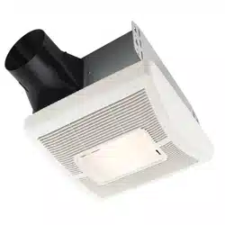
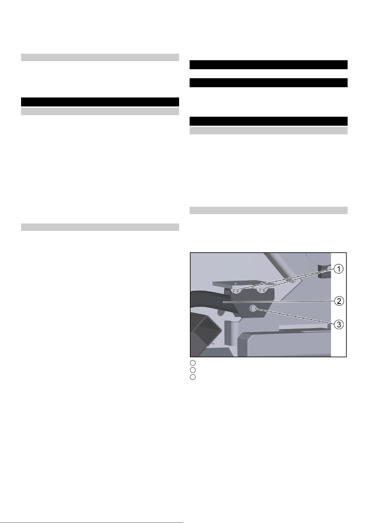
1. Den Halter mit der Schraube M8x35 (2x) am Rahmen befesti-
gen.
1 Bügel
2 Halter
3 Selbstsichernde Mutter
2. Den Bügel mit Schraube M12x70 und der selbstsichernden
Mutter am Halter befestigen.
3. Den Vorgang auf der gegenüberliegenden Seite wiederholen.
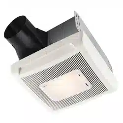
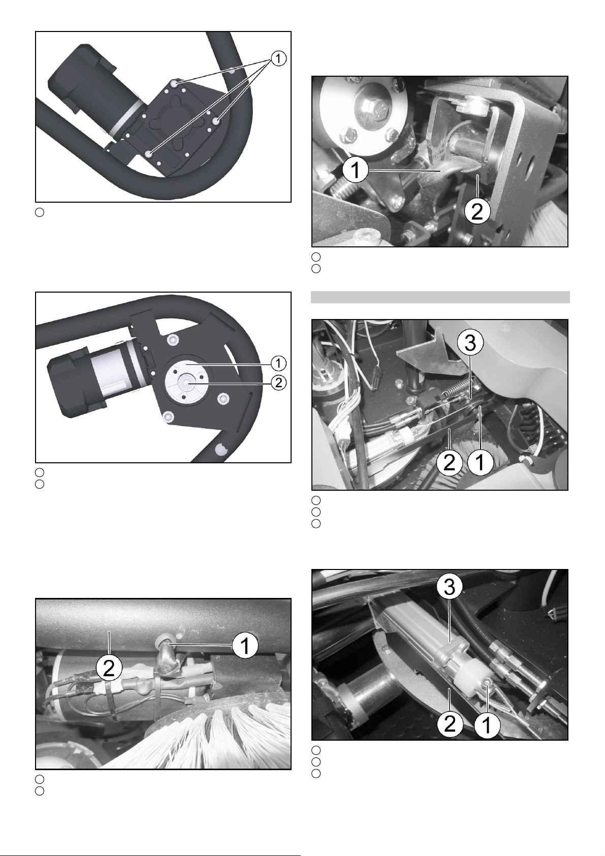
4. Den Seitenbesenmotor auf die Auflage am Bügel legen und
mit der Schraube (3x) und der selbsichernden Mutter fest-
schrauben.
1 Schraube M6x55
5. Den Entstörfilter an das Anschlusskabel anschließen.
6. Den Entstörfilter am Seitenbesenmotor befestigen.
Deutsch 3
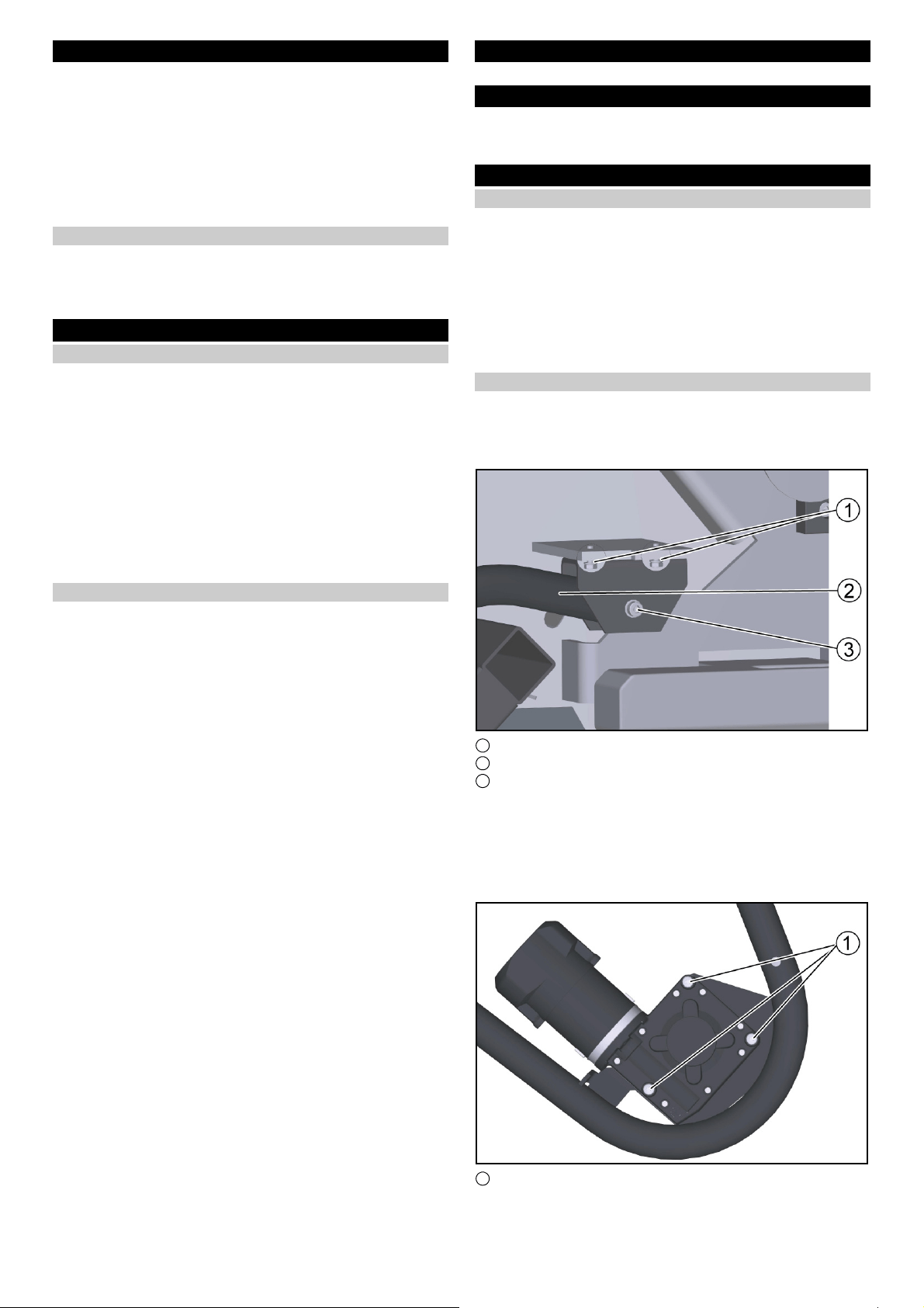
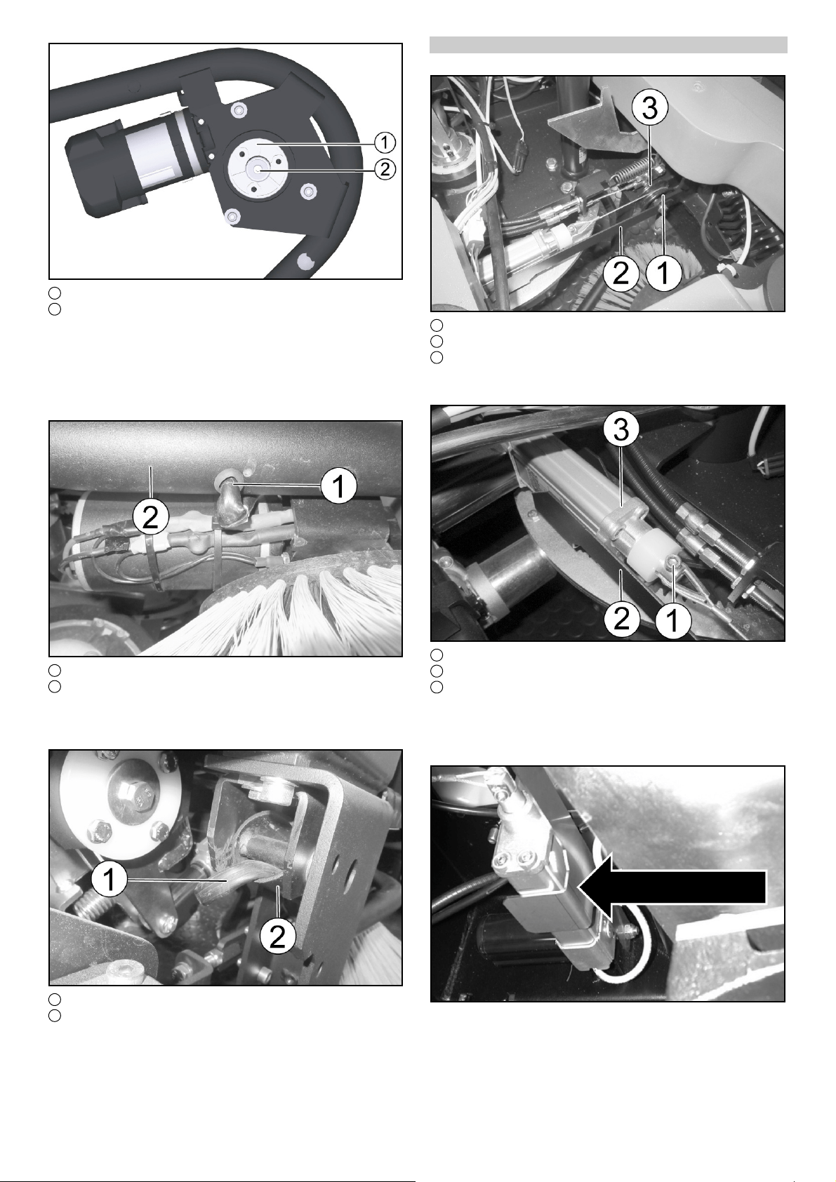
7. Das Anschlusskabel am Motor anbringen (rotes Kabel am au-
ßen liegenden Anschluss).
1 Mitnehmernabe
2 Schraube M6x16, Scheibe
8. Die Mitnehmernabe mit der Passfeder ansetzen und einschie-
ben.
9. Die Mitnehmernabe mit der Schraube und der Unterlegschei-
be befestigen.
Hinweis
Den korrekten Sitz der Passfeder überprüfen.
10.Den Seitenbesen aufsetzen und mit der Schraube M6x16 (3x)
befestigen.
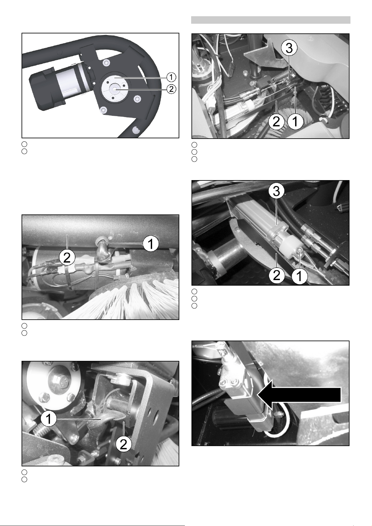
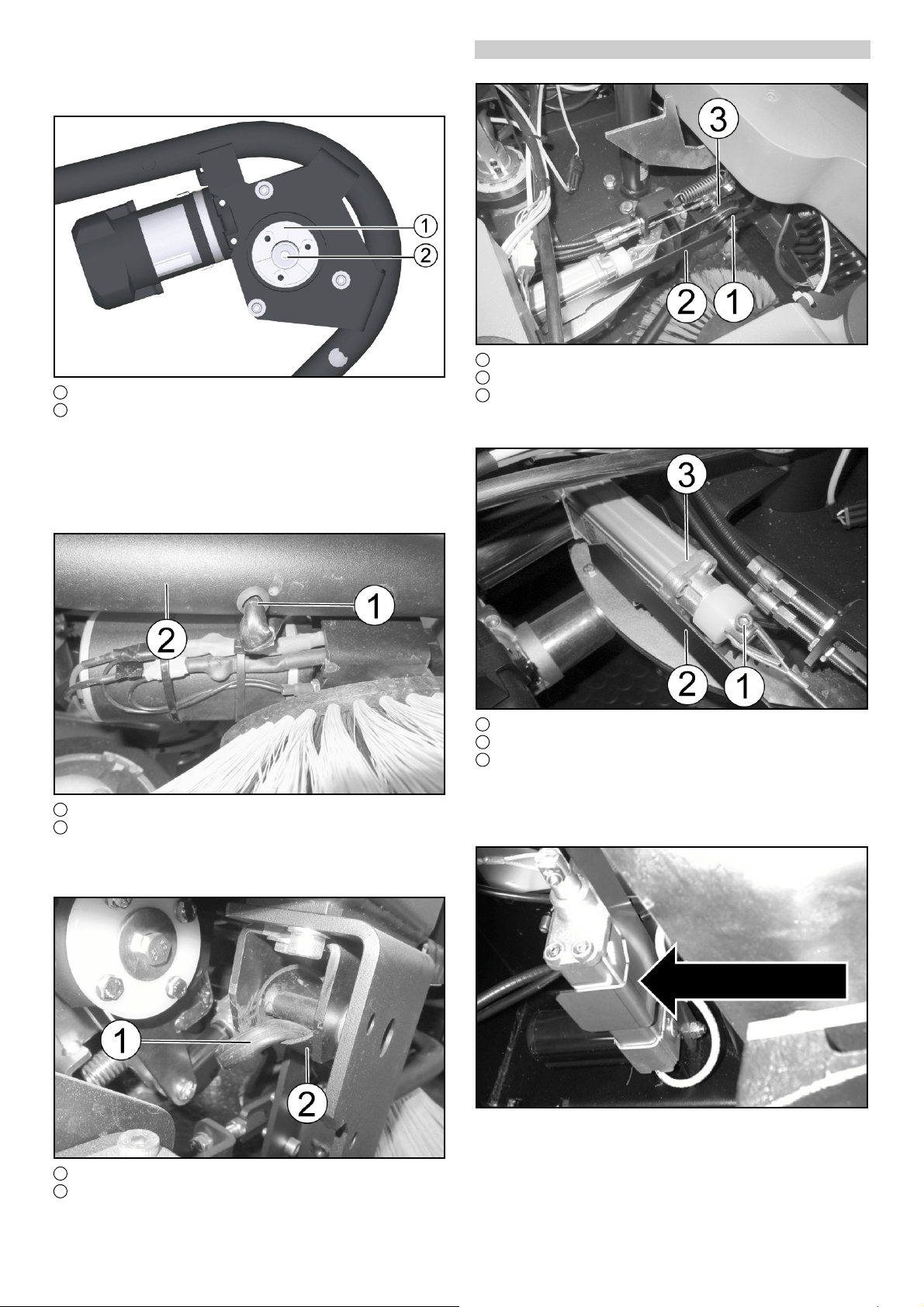
1 Kabel mit Kabeltülle
2 Bügel
11.Die Kabeltülle auf das Kabel schieben.
12.Das Kabel in den Bügel einfädeln, durch das Rohr führen und
fachgerecht zum Elektronikraum verlegen.
1 Kabel mit Kabeltülle
2 Bügel
Den Vorgang auf der gegenüberliegenden Seite wiederholen.
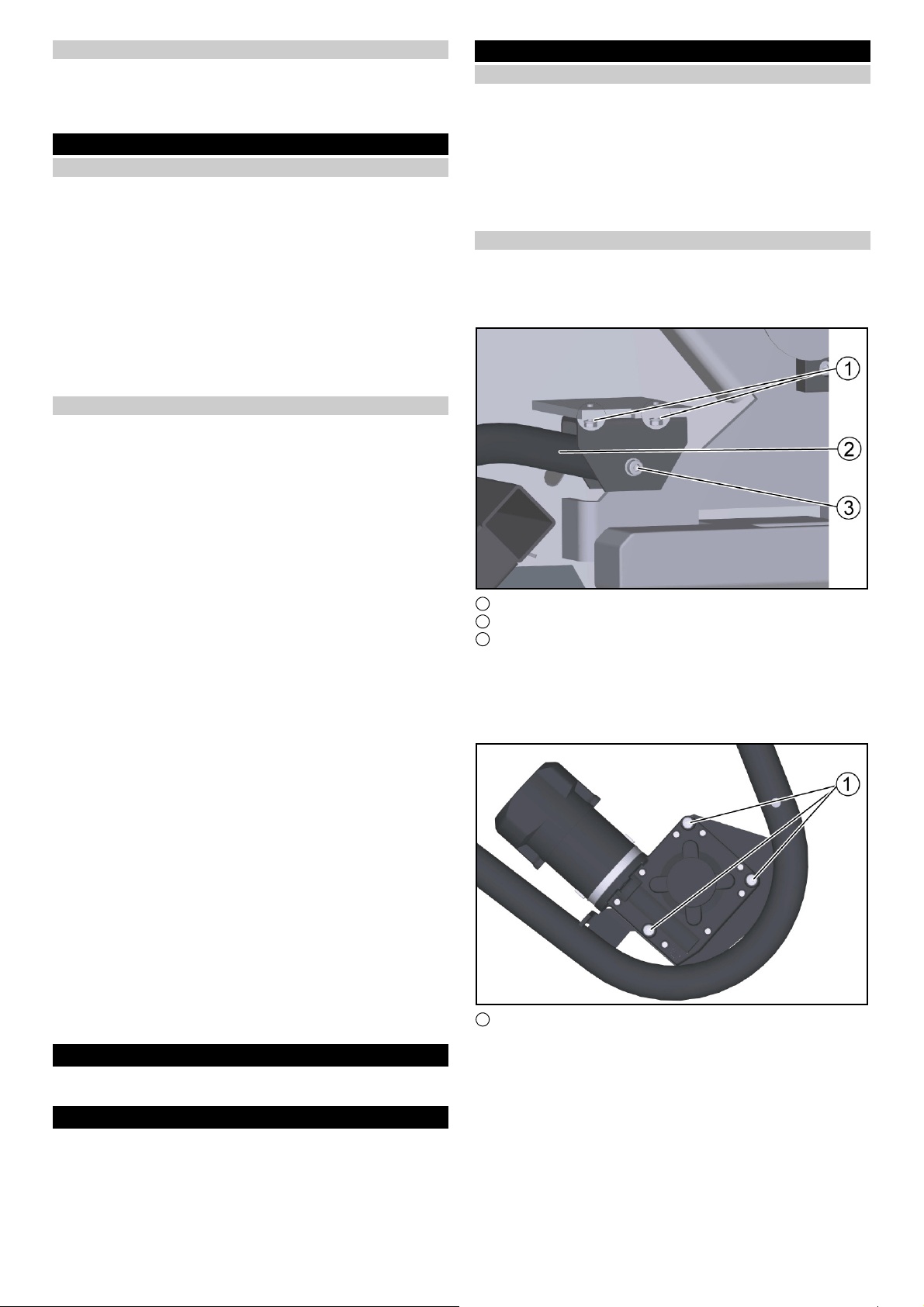
Hubmotor montieren
1. Das Bodenblech ausbauen.
1 Umlenkrolle
2 Halteblech
3 Halter
2. Das Halteblech und die Umlenkrolle am Halter mit Schraube
M8x45 und selbstsichernder Mutter befestigen.
1 Halter
2 Halteblech
3 Hubmotor
3. Den Hubmotor am Halter mit der Schraube M8x45 und der
Mutter befestigen.
4. Das Halteblech auf das Schraubenende aufstecken und mit
der selbstsichernden Mutter befestigen.
Das Halteblech dient als Auflage für den Hubmotor (Ansicht
von unten).

4 Deutsch
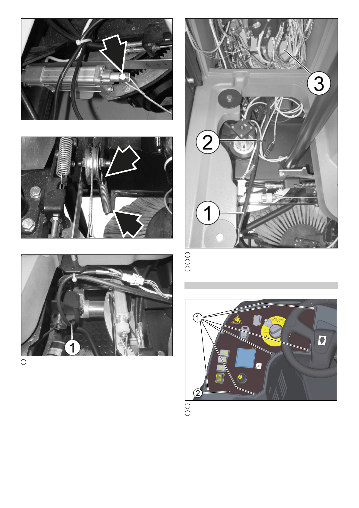
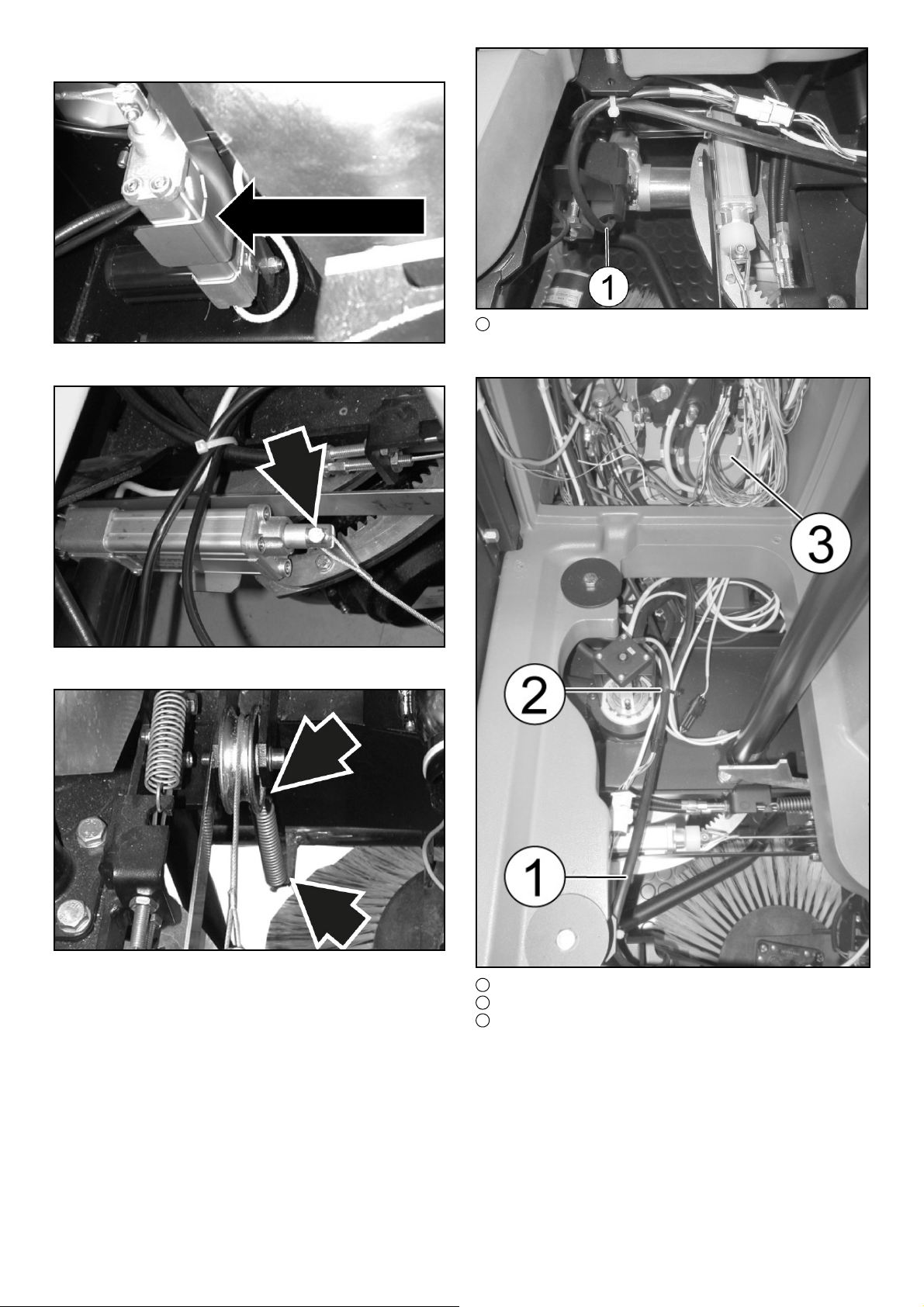
5. Das Zugseil mit der Schraube M6x25 und der selbstsichern-
den Mutter an den Hubmotor einhängen.
6. Die Zugfeder im Zugseil und im Bügel des Seitenbesens ein-
hängen.
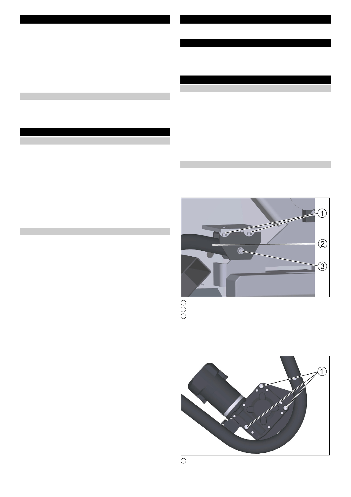
1 Anschlusskabel
7. Das Anschlusskabel des Hubmotors fachgerecht von unten in
den Elektronikraum verlegen.
1 Anschlusskabel
2 Kabelbinder
3 Elektronikraum
8. Das Anschlusskabel mit Kabelbindern sichern.
Schalter einbauen
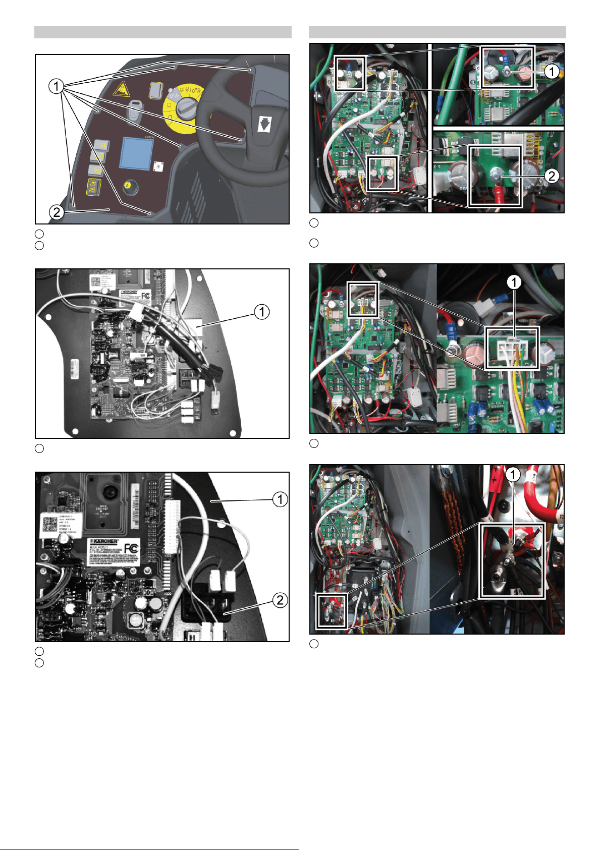
1. Die Schraube (7x) herausdrehen.
1 Schraube
2 Bedienfeld
2. Das Bedienfeld abnehmen.
English 5
1 Steckplatz
3. Die Folie über dem Schaltersteckplatz ausschneiden.
1 Bedienfeld
2 Schalter Seitenbesen
4. Den Schalter für den Seitenbesen in dem Bedienfeld einras-
ten.
5. Den Freien Steckverbinder am Schalter einstecken.
6. Das Bedienfeld wieder einbauen.
7. Die Schraube (7x) eindrehen.
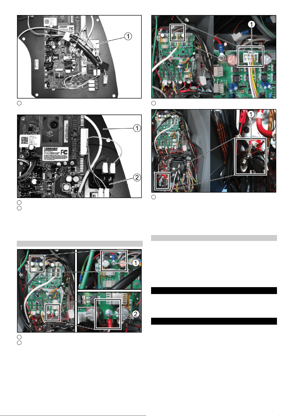
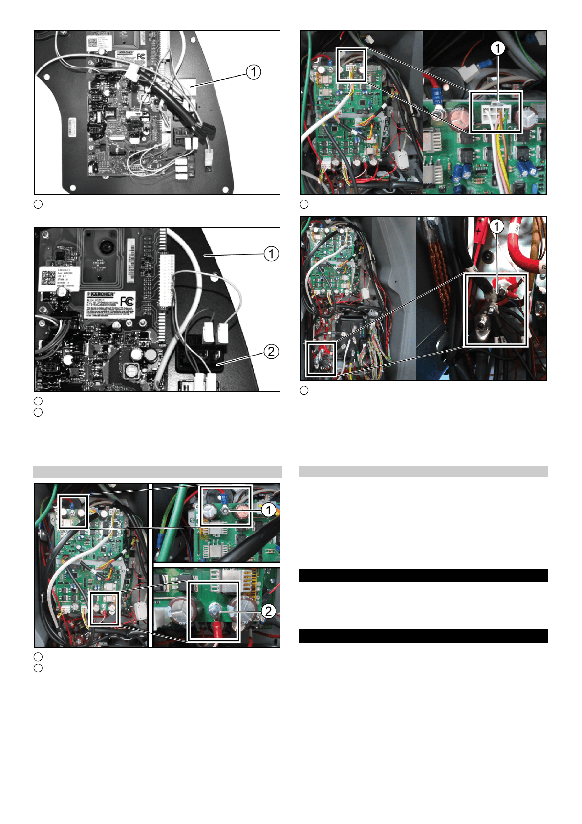
Steuerung verbinden
1 Seitenbesenmotor links: Hubmodul 2, Steckplatz X6
2 Seitenbesenmotor rechts: Hubmodul 1, Steckplatz X6
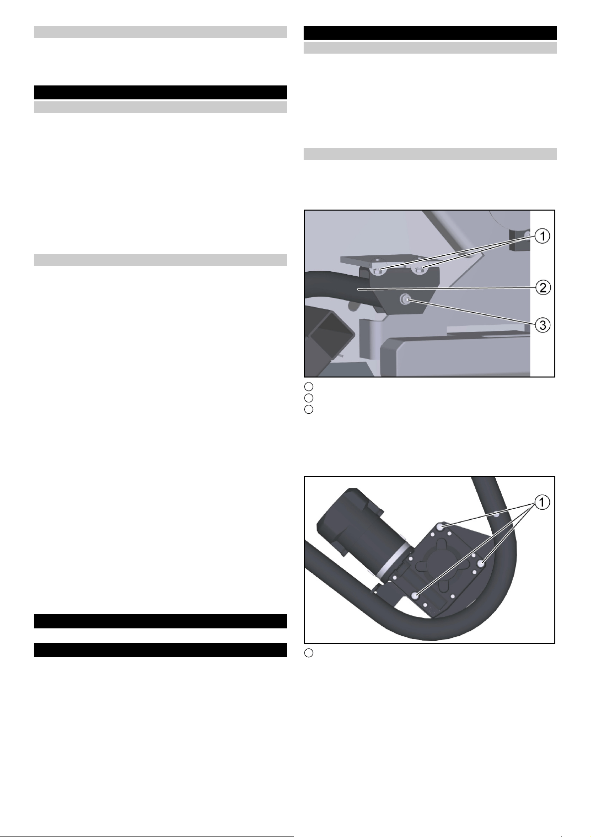
1 Hubmotor Seitenbesen: Hubmodul 2, Steckplatz X5
1 Massepunkt
1. Die Kabel Pluspol und Seitenbesen mit den Anschlüssen ver-
binden.
Verbinden Sie rot mit rot und weiß mit weiß.
2. Verbinden Sie das Kabel des Hubmotors mit dem Anschluss.
3. Die beiden Kabel des Seitenbesens (Minuspol) mit dem Mas-
sepunkt verbinden.
Anbausatz aktivieren
Hinweis
Zur Aktivierung des Anbausatzes wird der rote KIK benötigt.
1. Den roten KIK auflegen.
2. Den Info-Button drücken.
3. Das Menü “Anbausätze” auswählen.
4. Mit dem Info-Button auf den Anbausatz “Seitenbesen” drehen.
5. Den Info-Button drücken und den Anbausatz “Seitenbesen”
aktivieren.
Funktionsprüfung
1. Die Batterie anklemmen.
2. Das Gerät einschalten.
3. Den Knopf “Seitenbesen” auf dem Bedienfeld drücken.
4. Die Funktion von “Seitenbesen” kontrollieren.
Description
몇 CAUTION
Material damage through incorrect installation
Allow only qualified staff to perform the installation.
For safety and warranty reasons, installation must be carried out
by Kärcher Service.
Note
Also observe the operating instructions and safety instructions of
the unit in which the attachment kit is installed.
6 English
Intended use
These installation instructions describe the installation process
for the side brush.
It can be mounted on the following vehicle.
● B 260 RI
Safety instructions
Hazard levels
DANGER
● Indication of an imminent threat of danger that will lead to se-
vere injuries or even death.
몇 WARNING
● Indication of a potentially dangerous situation that may lead to
severe injuries or even death.
몇 CAUTION
● Indication of a potentially dangerous situation that may lead to
minor injuries.
ATTENTION
● Indication of a potentially dangerous situation that may lead to
damage to property.
Safety instructions
ATTENTION
Risk of damage due to improper installation.
Improper installation or connecting up of the attachment can
damage the attachment as well as the vehicle or the machine.
Malfunctions and failures can occur on the attachment and the
vehicle or machine.
Have the assembly, installation and connecting up of the attach-
ment carried out only by a qualified specialist.
ATTENTION
Risk of damage due to electrostatic discharge (ESD)!
Electrostatic discharge (ESD) can damage electronic compo-
nents.
Take suitable measures to discharge the electrostatic charge be-
fore all work on the device electronics.
ATTENTION
Risk of damage due to sharp-edged objects and soiling!
Sharp-edged or dirty objects can cause damage such as scratch-
es, notches and deformation when coming into contact with de-
vice components. Dirty tools, cloths and work surfaces can cause
irreversible soiling and discolouration.
Use only suitable, undamaged and clean tools and auxiliary ma-
terials and exercise care when working. Place components and
devices only on clean, padded surfaces.
For safety and warranty reasons, we recommend that you have
Kärcher Service perform the assembly, installation and connec-
tion.
Keep these installation instructions for future reference or for fu-
ture owners.
Note
Also adhere to the operating instructions for the vehicle or device
in which the attachment is installed.
Order numbers and spare parts
You can find all order numbers and spare parts in DISIS.
Preparatory work
● Turn the programme selection switch to the “0” position.
● Pull out the KÄRCHER Intelligent Key (KIK) on the control
panel.
● Disconnect the battery plug.
Installation
Preparation for installation
몇 CAUTION
Material damage through incorrect installation
Allow only qualified staff to perform the installation.
1. Place the device on a level surface.
2. Switch off the device.
Note
After installation, keep the installation instructions and the circuit
diagram together with the operating instructions.
Installing the side brush
ATTENTION
Disconnect the vehicle battery at the negative terminal before
starting work!
1. Fasten the holder to the frame with the M8x35 screws (2x).
1 Bracket
2 Holder
3 Self-locking nut
2. Fasten the bracket to the holder with the M12x70 screw and
the self-locking nut.
3. Repeat the entire procedure at the other side.
4. Place the side brush motor on the support on the bracket and
tighten it with the screw (3x) and the self-locking nut.
1 Screw M6x55
5. Connect the interference suppression filter to the connection
cable.
6. Fasten the interference suppression filter to the side brush
motor.
7. Attach the connection cable to the motor (red cable on the out-
er connection).

English 7
1 Driver hub
2 Screw M6x16, washer
8. Position the driver hub with the feather key and push it in.
9. Fasten the driver hub with the screw and washer.
Note
Check that the feather key is fitted correctly.
10.Fit the side brush and fasten it with the M6x16 screw (3x).
1 Cable with cable grommet
2 Bracket
11.Push the cable grommet onto the cable.
12.Thread the cable into the bracket, guide it through the pipe
and route it properly to the electronics compartment.
1 Cable with cable grommet
2 Bracket
Repeat the entire procedure at the other side.
Installing the lifting motor
1. Remove the floor plate.
1 Guide pulley
2 Retaining plate
3 Holder
2. Fasten the retaining plate and the pulley to the holder with the
M8x45 screw and self-locking nut.
1 Holder
2 Retaining plate
3 Lifting motor
3. Fasten the lifting motor to the holder with the M8x45 screw and
nut.
4. Fit the retaining plate onto the end of the screw and fasten it
with the self-locking nut.
The retaining plate serves as a support for the lifting motor
(view from below).

8 English
5. Hook the tow rope to the lifting motor with the M6x25 screw
and the self-locking nut.
6. Hook the tension spring into the tow rope and into the bracket
of the side brush.
1 Connection cable
7. Lay the connection cable of the lifting motor properly from be-
low into the electronics compartment.
1 Connection cable
2 Cable ties
3 Electronics compartment
8. Secure the connection cable with cable ties.
Installing the switch
1. Unscrew the screw (7x).
1 Screw
2 Control panel
2. Remove the control panel.
Français 9
1 Socket
3. Cut out the film over the switch socket.
1 Control panel
2 Side brush switch
4. Latch the switch for the side brush into the control panel.
5. Plug in the free connector at the switch.
6. Reinstall the control panel.
7. Screw in the screw (7x).
Connecting the controller
1 Side brush motor, left: Lifting module 2, slot X6
2 Side brush motor, right: Lifting module 1, slot X6
1 Lifting motor of side brushes: Lifting module 2, slot X5
1 Ground point
1. Connect the cables of the positive terminal and side brush to
the connections.
Connect red to red and white to white.
2. Connect the cable of the lifting motor to the connection.
3. Connect the two cables of the side brush (negative terminal)
to the ground point.
Activating the attachment kit
Note
The red KIK is required for activating the attachment kit.
1. Fit the red KIK.
2. Press the Info button.
3. Select the “Attachment kits” menu.
4. Turn to the attachment kit “Side brush” with the Info button.
5. Press the Info button and activate the attachment kit “Side
brush”.
Function test
1. Connect the battery.
2. Switch the device on.
3. Press the “Side brush” button on the control panel.
4. Check the function of “Side brush”.
Description
몇 PRÉCAUTION
Dégâts matériels dus à un montage mal effectué
Confier le montage à un spécialiste qualifié pour ce faire.
Pour des raisons de sécurité et de garantie, le montage doit être
effectué par le service Kärcher.
Remarque
Respecter également le mode d'emploi et les consignes de sécu-
rité de l'appareil dans lequel le kit de montage est installé.
10 Français
Utilisation conforme
Les présentes instructions de montage décrivent l’installation du
balai latéral.
Le kit peut être monté sur le véhicule suivant :
● B 260 RI
Consignes de sécurité
Niveaux de danger
DANGER
● Indique un danger immédiat qui peut entraîner de graves bles-
sures corporelles ou la mort.
몇 AVERTISSEMENT
● Indique une situation potentiellement dangereuse qui peut en-
traîner de graves blessures corporelles ou la mort.
몇 PRÉCAUTION
● Indique une situation potentiellement dangereuse qui peut en-
traîner des blessures légères.
ATTENTION
● Indique une situation potentiellement dangereuse qui peut en-
traîner des dommages matériels.
Consignes de sécurité
ATTENTION
Risque d’endommagement dû à une installation incorrecte.
Une installation ou un raccordement incorrect(e) de l’accessoire
peut l’endommager, ainsi que le véhicule ou la machine. Des dys-
fonctionnements et des pannes peuvent survenir sur l’accessoire
et le véhicule ou la machine.
Confiez le montage, l’installation et le raccordement de l’acces-
soire uniquement à un spécialiste qualifié à cet effet.
ATTENTION
Risque d'endommagement par décharge électrostatique
(ESD) !
Une décharge électrostatique (electrostatic discharge, ESD) peut
endommager les sous-ensembles électroniques.
Prendre les mesures nécessaires pour décharger les charges
électrostatiques du système électronique et électrique avant les
travaux.
ATTENTION
Risque d'endommagement dû aux objets tranchants et aux
encrassements !
En cas de contact avec les sous-ensembles, les objets tran-
chants ou encrassés peuvent provoquer des dommages tels que
des rayures, des entailles et des déformations. Les outils, chif-
fons et plans de travail encrassés peuvent provoquer des encras-
sements et des changement de couleur irréversibles.
Utiliser exclusivement des outils et des moyens auxiliaires adap-
tés, non endommagés et propres et agir avec prudence. Déposer
les sous-ensembles et les appareils uniquement sur des sup-
ports propres et rembourrés.
Pour des raisons de sécurité et de garantie, nous recommandons
de confier le montage, l’installation et le raccordement au person-
nel de service Kärcher.
Conservez ces instructions de montage pour une utilisation ulté-
rieure ou pour le propriétaire suivant.
Remarque
Tenez compte également du manuel d’utilisation du véhicule ou
de l’appareil dans lequel l’accessoire est monté.
Références et pièces de rechange
Vous trouverez toutes les références et pièces de rechange dans
le DISIS.
Travaux préliminaires
● Tourner le sélecteur de programme en position « 0 ».
● Retirer la KÄRCHER Intelligent Key (KIK) du pupitre de com-
mande.
● Débrancher la fiche de la batterie.
Montage
Préparation du montage
몇 PRÉCAUTION
Dégâts matériels dus à un montage mal effectué
Confier le montage à un spécialiste qualifié pour ce faire.
1. Placer l'appareil sur une surface plane.
2. Éteindre l'appareil.
Remarque
Une fois le montage terminé, conservez les instructions de mon-
tage et le schéma électrique avec le manuel d'utilisation.
Monter le balai latéral
ATTENTION
Avant de commencer les travaux, débrancher la batterie du véhi-
cule de la borne négative !
1. Fixer le support au cadre avec la vis M8x35 (2x).
1 Etrier
2 Support
3 Écrou autobloquant
2. Fixer l'étrier au support avec la vis M12x70 et l'écrou autoblo-
quant.
3. Répéter la procédure du côté opposé.
4. Poser le moteur du balai latéral sur le support de l'étrier et le
visser avec la vis (3x) et l'écrou autobloquant.
1 Vis M6x55
5. Raccorder le filtre antiparasite au câble de raccordement.
6. Fixer le filtre antiparasite sur le moteur du balai latéral.
7. Fixer le câble de raccordement au moteur (câble rouge sur le
raccord situé à l'extérieur).
Français 11
1 Moyeu d'entraînement
2 Vis M6x16, rondelle
8. Placer le moyeu d'entraînement avec la clavette et l'insérer.
9. Fixer le moyeu d'entraînement avec la vis et la rondelle.
Remarque
Vérifier le bon positionnement de la clavette.
10.Mettre en place le balai latéral et le fixer avec la vis M6x16
(3x).
1 Câble avec passe-câble
2 Etrier
11.Pousser le passe-câble sur le câble.
12.Enfiler le câble dans l'étrier, le faire passer dans le tube et le
poser correctement jusqu'à l’espace électronique.
1 Câble avec passe-câble
2 Etrier
Répéter la procédure du côté opposé.
Monter le moteur de levage
1. Démonter la tôle de fond.
1 Poulie de renvoi
2 Tôle de maintien
3 Support
2. Fixer la tôle de maintien et la poulie de renvoi au support avec
une vis M8x45 et un écrou autobloquant.
1 Support
2 Tôle de maintien
3 Moteur de levage
3. Fixer le moteur de levage au support avec la vis M8x45 et
l'écrou.
4. Placer la tôle de maintien sur l'extrémité de la vis et la fixer
avec l'écrou autobloquant.
La tôle de maintien sert de support au moteur de levage (vue
d'en bas).

12 Français
5. Accrocher le câble de traction au moteur de levage à l'aide de
la vis M6x25 et de l'écrou autobloquant.
6. Accrocher le ressort de traction dans le câble de traction et
dans l'étrier du balai latéral.
1 Câble de raccordement
7. Poser correctement le câble de raccordement du moteur de
levage par le bas dans l’espace électronique.
1 Câble de raccordement
2 Serre-câble
3 Espace électronique
8. Bloquer le câble de raccordement avec des serre-câbles.
Montage de l'interrupteur
1. Retirer la vis (7x).
1 Vis
2 Tableau de commande
2. Retirer le panneau de commande.

Français 13
1 Port
3. Couper le film sur le port de l'interrupteur.
1 Tableau de commande
2 Interrupteur des balais latéraux
4. Enclencher l'interrupteur des balais latéraux dans le tableau
de commande.
5. Brancher le connecteur libre sur l'interrupteur.
6. Remettre le tableau de commande en place.
7. Visser la vis (7x).
Connecter la commande
1 Moteur du balai latéral à gauche : Module de levage 2, empla-
cement X6
2 Moteur du balai latéral à droite : Module de levage 1, empla-
cement X6
1 Moteur de levage du balai latéral : Module de levage 2, em-
placement X5
1 Centre de la masse
1. Connecter les câbles pôle plus et les balais latéraux aux rac-
cordements.
Relier le rouge au rouge et le blanc au blanc.
2. Brancher le câble du moteur de levage sur le raccordement.
3. Relier les deux câbles du balai latéral (pôle négatif) au point
de masse.
Activer le kit de montage
Remarque
Le KIK rouge est nécessaire pour activer le kit de montage.
1. Mettre le KIK rouge.
2. Appuyer sur le bouton Info.
3. Sélectionner le menu « Kits de montage ».
4. Tourner le bouton d'information sur le kit de montage « Balais
latéraux ».
5. Appuyer sur le bouton d'information et activer le kit de mon-
tage « Balais latéraux ».
Test de fonctionnement
1. Brancher la batterie.
2. Démarrer l’appareil.
3. Appuyer sur le bouton « Balais latéraux » sur le tableau de
commande.
4. Contrôler le fonctionnement de « Balais latéraux ».
14 Español
Descripción
몇 PRECAUCIÓN
Daños materiales por un montaje defectuoso
El montaje debe realizarlo únicamente el personal especialista
formado para ello.
Por motivos de garantía y seguridad, el montaje debe realizarse
por parte del servicio técnico de Kärcher.
Nota
Observe también el manual de instrucciones y las instrucciones
de seguridad del equipo en que está instalado el juego de mon-
taje.
Uso previsto
En estas instrucciones de montaje se describe el montaje de los
cepillos laterales.
Se puede montar en el siguiente vehículo.
● B 260 RI
Instrucciones de seguridad
Niveles de peligro
PELIGRO
● Aviso de un peligro inminente que produce lesiones corporales
graves o la muerte.
몇 ADVERTENCIA
● Aviso de una posible situación peligrosa que puede producir le-
siones corporales graves o la muerte.
몇 PRECAUCIÓN
● Aviso de una posible situación peligrosa que puede producir le-
siones corporales leves.
CUIDADO
● Aviso de una posible situación peligrosa que puede producir
daños materiales.
Instrucciones de seguridad
CUIDADO
Peligro de daños debido a una instalación incorrecta.
Una instalación o conexión incorrectas del accesorio pueden da-
ñarlo y dañar también el vehículo o la máquina. Pueden produ-
cirse averías y fallos de funcionamiento en el accesorio, el
vehículo o la máquina.
El montaje, la instalación y la conexión del accesorio deberán en-
cargarse exclusivamente a un personal especialista cualificado.
CUIDADO
Peligro de daños por descargas electrostáticas (ESD).
Las descargas electrostáticas (electrostatic discharge, ESD)
pueden dañar los componentes eléctricos.
Antes de realizar cualquier trabajo en el sistema electrónico y
eléctrico, tome las medidas pertinentes para disipar las cargas
electrostáticas.
CUIDADO
Peligro de daños por objetos con bordes afilados y sucie-
dad.
Los objetos con bordes afilados o sucios pueden provocar da-
ños, si entran en contacto con los componentes, como arañazos,
muescas y deformaciones. Las herramientas, superficies de tra-
bajo y paños sucios pueden provocar manchas y decoloraciones
irreversibles.
Utilice únicamente herramientas e instrumentos adecuados, en
buen estado y limpios y utilícelos de forma prudente. Deposite
los componentes y los equipos únicamente sobre bases limpias
y acolchadas.
Por motivos relacionados con la garantía y la seguridad, reco-
mendamos que el montaje, la instalación y la conexión los realice
el servicio técnico de Kärcher.
Conserve las instrucciones de montaje para su uso posterior o
para futuros propietarios.
Nota
También debe tenerse en cuenta el manual de instrucciones del
vehículo o el equipo en el que se va a montar el accesorio.
Referencias de pedido y recambios
En DISIS encontrará todas las referencias de pedido y recam-
bios.
Trabajos previos
● Gire el selector de programas a la posición “0”.
● Extraiga la KÄRCHER Intelligent Key (KIK) del terminal de
control.
● Desconectar el conector de la batería.
Montaje
Preparación del montaje
몇 PRECAUCIÓN
Daños materiales por un montaje defectuoso
El montaje debe realizarlo únicamente el personal especialista
formado para ello.
1. Depositar el equipo sobre una superficie plana.
2. Desconectar el equipo.
Nota
Después de la instalación, conservar las instrucciones de monta-
je y el esquema de los circuitos junto con el manual de instruc-
ciones.
Montaje del cepillo lateral
CUIDADO
Antes de empezar a trabajar, desconectar la batería del vehículo
por el borne negativo.
1. Fijar el soporte al marco con el tornillo M8x35 (2x).
1 Estribo
2 Soporte
3 Tuerca de autosujeción
2. Fijar el estribo en el soporte con el tornillo M12x70 y la tuerca
autoblocante.
3. Repetir el proceso en el lado opuesto.
4. Colocar el motor de los cepillos laterales en el soporte del es-
tribo y apretarlo con el tornillo (3x) y la tuerca autoblocante.
1 Tornillo M6x55
Español 15
5. Conectar el filtro de ruido en el cable de conexión.
6. Fijar el filtro de ruido en el motor de los cepillos laterales.
7. Colocar el cable de conexión al motor (cable rojo en la cone-
xión exterior).
1 Buje del arrastrador
2 Tornillo M6x16, arandela
8. Colocar el buje del arrastrador con la chaveta de ajuste y em-
pujarlo.
9. Fijar el buje del arrastrador con el tornillo y la arandela.
Nota
Comprobar el ajuste correcto de la chaveta de ajuste.
10.Colocar el cepillo lateral y fijarlo con el tornillo M6x16 (3x).
1 Cable con pasacables
2 Estribo
11.Empujar el pasacables en el cable.
12.Enroscar el cable en el estribo, guiarlo a través de la tubería
y colocarlo correctamente en la sala de electrónica.
1 Cable con pasacables
2 Estribo
Repetir el proceso en el lado opuesto.
Montar el motor elevador
1. Desmontar el panel del suelo.
1 Polea inversora
2 Chapa de sujeción
3 Soporte
2. Fijar la chapa de sujeción y la polea al soporte con un tornillo
M8x45 y una tuerca autoblocante.
1 Soporte
2 Chapa de sujeción
3 Motor elevador
3. Fijar el motor elevador al soporte con el tornillo M8x45 y la
tuerca.
4. Colocar la chapa de sujeción en el extremo del tornillo y fijarla
con la tuerca autoblocante.
La chapa de sujeción sirve de soporte para el motor elevador
(vista desde abajo).
16 Español
5. Enganchar la cuerda de tracción al motor elevador con el tor-
nillo M6x25 y la tuerca autoblocante.
6. Enganchar el muelle de tracción en la cuerda de tracción y en
el soporte del cepillo lateral.
1 Cable de conexión
7. Tender correctamente el cable de conexión del motor elevador
desde abajo en la sala de electrónica.
1 Cable de conexión
2 Abrazadera de cables
3 Sala de electrónica
8. Asegurar el cable de conexión con abrazaderas de cables.
Instalar el interruptor
1. Desenroscar el tornillo (7x).
1 Tornillo
2 Panel de control
2. Retirar el campo de control inferior.

Русский 17
1 Puesto de enchufe
3. Recortar la lámina por encima del puesto de interruptor libre.
1 Panel de control
2 Interruptor del cepillo lateral
4. Accionar el interruptor del cepillo lateral en el campo de con-
trol.
5. Enchufar el conector libre del interruptor.
6. Volver a instalar el campo de control.
7. Atornillar el tornillo (7x).
Conectar el control
1 Motor de los cepillos laterales a la izquierda: Módulo de ele-
vación 2, ranura X6
2 Motor de los cepillos laterales a la derecha: Módulo de eleva-
ción 1, ranura X6
1 Motor de elevación de los cepillos laterales: Módulo de eleva-
ción 2, ranura X5
1 Punto de masa
1. Conectar ambos cables de polo positivo de los cepillos latera-
les con las conexiones.
Conectar el rojo con el rojo y el blanco con el blanco.
2. Conectar el cable del motor elevador a la conexión.
3. Conectar los dos cables del cepillo lateral (polo negativo) al
punto de tierra.
Activar el juego de montaje
Nota
El KIK rojo es necesario para activar el juego de montaje.
1. Colocar el KIK rojo.
2. Pulsar el botón de información.
3. Seleccionar el menú «Juegos de montaje».
4. Girar con el botón de información en el juego de montaje «Ce-
pillos laterales».
5. Pulsar el botón de información y activar el juego de montaje
«Cepillos laterales».
Comprobación de funcionamiento
1. Conectar la batería.
2. Conectar el equipo.
3. Pulsar el botón "Cepillos laterales" en el campo de control.
4. Comprobar la función de "Cepillos laterales".
Описание
몇 ОСТОРОЖНО
Материальный ущерб из-за неправильного монтажа
Поручать проведение монтажа только специалистам,
имеющим соответствующую квалификацию.
Из соображений безопасности и для сохранения гарантии
поручить установку оборудования сервисной службе Kärcher.
18 Русский
Примечание
Соблюдать также указания, приведенные в инструкции по
эксплуатации и указания по технике безопасности
устройства, в которое будет устанавливаться
монтажный комплект.
Использование по назначению
В данной инструкции по монтажу описывается установка
боковой щетки.
Она может быть установлена на следующее транспортное
средство.
● B 260 RI
Указания по технике безопасности
Степень опасности
ОПАСНОСТЬ
● Указание относительно непосредственно грозящей
опасности, которая приводит к тяжелым травмам или к
смерти.
몇 ПРЕДУПРЕЖДЕНИЕ
● Указание относительно возможной потенциально
опасной ситуации, которая может привести к тяжелым
травмам или к смерти.
몇 ОСТОРОЖНО
● Указание на потенциально опасную ситуацию, которая
может привести к получению легких травм.
ВНИМАНИЕ
● Указание относительно возможной потенциально
опасной ситуации, которая может повлечь за собой
материальный ущерб.
Указания по технике безопасности
ВНИМАНИЕ
Опасность повреждения из-за неправильной
установки.
Неправильная установка или подключение навесного
оборудования может привести к повреждению навесного
оборудования, а также транспортного средства или
машины. На навесном оборудовании и транспортном
средстве или машине могут возникнуть сбои и отказы.
Монтаж, установка и подключение навесного оборудования
должны выполняться только квалифицированными
специалистами.
ВНИМАНИЕ
Опасность повреждения вследствие
электростатического разряда (ЭСР)!
Электростатический разряд (electrostatic discharge, ЭСР)
может причинить вред электронному оборудованию.
Перед проведением любых работ с электроникой и
электрооборудованием следует предпринять
соответствующие меры для отвода
электростатического заряда.
ВНИМАНИЕ
Опасность повреждения об острые и грязные
предметы!
Острые или грязные предметы при контакте с
конструктивными узлами могут стать причиной таких
повреждений, как царапины, зазубрины или деформация.
Грязные инструменты, ветошь и рабочие поверхности
могут вызвать необратимые загрязнения и изменения
цвета.
Использовать только подходящие, неповрежденные и
чистые инструменты и вспомогательные средства, при
обращении соблюдать осторожность. Конструктивные
узлы и устройства класть только на чистое основание с
мягкой подкладкой.
Из соображений безопасности и для сохранения гарантии
мы рекомендуем поручить монтаж, установку и подключение
оборудования сервисной службе Kärcher.
Сохранить инструкцию по монтажу для дальнейшего
пользования или для следующего владельца.
Примечание
Соблюдать также указания, приведенные в инструкции по
эксплуатации транспортного средства или устройства,
на которое устанавливается навесное оборудование.
Номера для заказа и запасные части
Все номера для заказа и запасные части приведены в DISIS.
Предварительные работы
● Установить переключатель выбора программ в положение
«0».
●Извлечь чип-ключ KÄRCHER (KIK) из пульта управления.
●Отсоединить штекер аккумулятора.
Монтаж
Подготовка к установке
몇 ОСТОРОЖНО
Материальный ущерб из-за неправильного монтажа
Поручать проведение монтажа только специалистам,
имеющим соответствующую квалификацию.
1. Поставить устройство на ровной поверхности.
2. Выключить устройство.
Примечание
После установки сохранить инструкцию по монтажу и
схему электрических соединений вместе с инструкцией по
эксплуатации.
Установка боковой щетки
ВНИМАНИЕ
Перед началом работы отсоединить аккумулятор
транспортного средства от отрицательного полюса!
1. Закрепить держатель на раме с помощью винтов M8x35
(2 шт.).
1 Скоба
2 Держатель
3 Самостопорящаяся гайка
2. Закрепить скобу на держателе с помощью винта M12x70 и
самостопорящейся гайки.
3. Повторить процедуру с противоположной стороны.
4. Поставить двигатель боковой щетки на подставку на скобе
и привинтить винтами (3 шт.) и самостопорящимися
гайками.
Русский 19
1 Винт M6x55
5. Присоединить фильтр подавления радиопомех к
соединительному кабелю.
6. Закрепить фильтр подавления радиопомех на двигателе
боковой щетки.
7. Подсоединить соединительный кабель к двигателю
(красный кабель к внешнему разъему).
1 Ступица захватного устройства
2 Винт M6x16, шайба
8. Вставить ступицу захватного устройства вместе с
призматической шпонкой.
9. Закрепить ступицу захватного устройства с помощью
винта и подкладной шайбы.
Примечание
Проверить правильность установки призматической
шпонки.
10.Насадить боковую щетку и закрепить с помощью винтов
M6x16 (3 шт.).
1 Кабель с наконечником
2 Скоба
11.Надеть на кабель наконечник.
12.Продеть кабель в скобу, провести через трубу и
надлежащим образом проложить к отсеку для
электроники.
1 Кабель с наконечником
2 Скоба
Повторить процедуру с противоположной стороны.
Установка подъемного двигателя
1. Снять днище.
1 Направляющий шкив
2 Крепежная пластина
3 Держатель
2. Закрепить крепежную пластину и направляющий шкив на
держателе с помощью винта M8x45 и самостопорящейся
гайки.
1 Держатель
2 Крепежная пластина
3 Подъемный двигатель
3. Закрепить подъемный двигатель на держателе с помощью
винта M8x45 и гайки.
20 Русский
4. Надеть крепежную пластину на конец винта и
зафиксировать самостопорящейся гайкой.
Крепежная пластина служит в качестве опоры для
подъемного двигателя (вид снизу).
5. Закрепить тяговый трос на подъемном двигателе с
помощью винта M6x25 и самостопорящейся гайки.
6. За тяговый трос и скобу боковой щетки зацепить натяжную
пружину.
1 Соединительный кабель
7. Правильно уложить соединительный кабель подъемного
двигателя снизу в отсек для электроники.
1 Соединительный кабель
2 Кабельная стяжка
3 Отсек для электроники
8. Закрепить соединительный кабель кабельными стяжками.
Русский 21
Установка переключателя
1. Выкрутить винты (7 шт.).
1 Винт
2 Панель управления
2. Снять панель управления.
1 Гнездо для подключения
3. Вырезать пленку поверх гнезда для переключателя.
1 Панель управления
2 Переключатель боковой щетки
4. Вставить переключатель для боковой щетки в панель
управления.
5. Вставить свободный штекерный соединитель на
переключателе.
6. Установить на место панель управления.
7. Вкрутить винты (7 шт.).
Соединение с системой управления
1 Двигатель боковой щетки слева: подъемный модуль 2,
гнездо X6
2 Двигатель боковой щетки справа: подъемный модуль 1,
гнездо X6
1 Подъемный двигатель боковой щетки: подъемный модуль
2, гнездо X5
1 Точка массы
1. Подсоединить кабель положительного полюса и боковой
щетки к разъемам.
Соединить красный кабель с красным и белый кабель с
белым.
2. Подсоединить кабель подъемного двигателя к разъему.
3. Подсоединить оба кабеля боковой щетки (отрицательный
полюс) к точке заземления.

22 Русский
Активация монтажного комплекта
Примечание
Для активации монтажного комплекта необходим красный
чип-ключ KIK.
1. Приложить красный чип-ключ KIK.
2. Нажать информационную кнопку.
3. Выбрать меню «Монтажные комплекты».
4. С помощью информационной кнопки перейти к
монтажному комплекту «Боковая щетка».
5. Нажать информационную кнопку и активировать
монтажный комплект «Боковая щетка».
Проверка функционирования
1. Присоединить клеммы аккумулятора.
2. Включить устройство.
3. Нажать кнопку «Боковая щетка» на панели управления.
4. Проверить функцию «Боковая щетка».

Русский 23

2-2-SC-A4-GS-aw19869