Loading ...
Loading ...
Loading ...
In order to avoid static electricity damage to the instrument
or the component under test, do not use it while charging
NOTE!
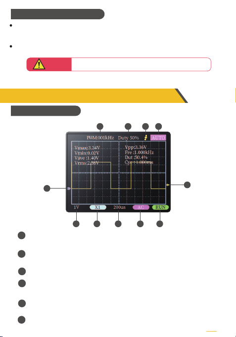
PWM square wave signal output frequency, the output range is
adjustable from 1-80KHz
PWM square wave signal output duty cycle, the output range is 0-100%
adjustable
Trigger edge indicator
Trigger mode indicator icon.Auto means automatic triggering.Single
means a single trigger.Normal means normal trigger
Baseline indicator icon.This icon indicates the position that the current
position is OV voltage
Trigger voltage indicator icon
1
2
3
4
5
6
5
1
78
9
10
234
11
6
【4.4】 Charging Interface
【5.1】 TFT Display
PAGE
The instrument is powered by a built-in lithium battery.There is a USB Type-C
charging port on the bottom.Connect to 5V charger for charging
The indicator light is solid red when charging, and the indicator light is solid
green when fully charged
Loading ...
Loading ...
Loading ...