30A PWM
Version 2.0
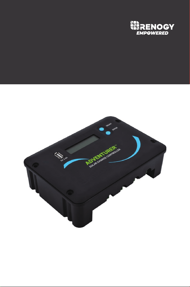
Flush Mount Charge Controller w/ LCD Display
ADVENTURER
01
General Safety Information
Charge Controller Safety
Important Safety Instructions
Please save these instructions.
This manual contains important safety, installation, and operating instructions for the
charge controller. The following symbols are used throughout the manual:
There are no serviceable parts for this controller. Do NOT disassemble or attempt to
repair the controller.
Make sure all connections going into and from the controller are tight. There may be
sparks when making connections, therefore, make sure there are not flammable
materials or gases near installation.
NEVER connect the solar panel array to the controller without a battery. Battery must
be connected first. This may cause a dangerous occurrence where the controller
would experience a high open circuit voltage at the terminals.
Ensure input voltage does not exceed 50 VDC to prevent permanent damage. Use
the Open Circuit (Voc) to make sure the voltage does not exceed this value when
connecting panels together in series.
The charge controller should be installed indoors in a well-ventilated, cool, and dry
environment.
Do NOT allow water to enter the controller.
Read all of the instructions and cautions in the manual before beginning the
installation.
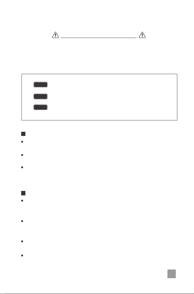
NOTE
CAUTION
WARNING
Indicates a potentially dangerous condition. Use extreme
caution when performing this task.
Indicates a critical procedure for safe and proper operation of
the controller.
Indicates a procedure or function that is important to the safe
and proper operation of the controller.
EN

02
Battery Safety
Do
NOT
let the positive (+) and negative (-) terminals of the battery touch each
other.
Explosive battery gases may be present while charging. Be certain there is
enough ventilation to release the gases.
Be careful when working with large lead acid batteries. Wear eye protection and
have fresh water available in case there is contact with the battery acid.
Over-charging and excessive gas precipitation may damage the battery plates
and activate material shedding on them. Too high of an equalizing charge or too
long of one may cause damage. Please carefully review the specific requirements
of the battery used in the system.
Equalization is carried out only for non-sealed / vented / flooded / wet cell lead
acid batteries.
Do NOT equalize VRLA type AGM / Gel / Lithium cell batteries UNLESS permitted
by battery manufacturer.
Connect battery terminals to the charge controller BEFORE
connecting the solar panel(s) to the charge controller.NEVER connect
solar panels to charge controller until the battery is connected.
Once equalization is active in the battery charging, it will not exit this
stage unless there is adequate charging current from the solar panel.
There should be NO load on the batteries when in equalization
charging stage.
WARNING
EN

Table of Contents
03
General Information
Product Overview
Identification of Parts
Included Components
Optional Components
Flush Mounting
Installation
Surface Mount Attachment
Maintenance
Wiring
Fusing
Operation
Change the Parameters
Lithium Battery Activation
Power Generation Interface -> Reset
Battery Interface -> Set Battery Type
Battery Temperature Interface -> Change from C° to F°
Set Battery Type to Lithium -> Set Lithium Parameters
04
05
05
13
13
14
14
06
07
07
08
09
10
10
17
12
System Status Icons
13
13
15
15
16
17
18
18
14
PWM Technology
Four Charging Stages
Battery Charging Parameters
System Status Troubleshooting
Technical Specifications
Dimensions
EN

04
General Information
4 Stage PWM charging: Bulk, Boost. Float, and Equalization.
Protection against: overcharging, over current, short-circuit, and reverse polarity.
Unique USB port on the front display.
Integrated communication port for remote monitoring
Charges over-discharged lithium iron-phosphate batteries
Remote temperature compensation compatible.
Remote battery voltage sensor compatible.
The Adventurer is an advanced charge controller for off-grid solar applications. Integrating
highly efficient PWM charging, this controller increases battery life and improved system
performance. It can be used for 12V or 24V battery or battery bank. The controller is
embedded with self-diagnostics and electronic protection functions that prevent damages
from installation mistakes or system faults.
Automatic recognition for 12V or 24V system voltage.
Backlit LCD screen for displaying system operating information and data.
30A charging capacity.
Compatible with AGM, Sealed, Gel, Flooded, and Lithium batteries.
Temperature compensation and correcting the charging and discharging parameters
automatically, improving battery lifetime.
Specifically designed for RV application and allows for aesthetically clean flush
mounting on walls.
Key Features
EN
05
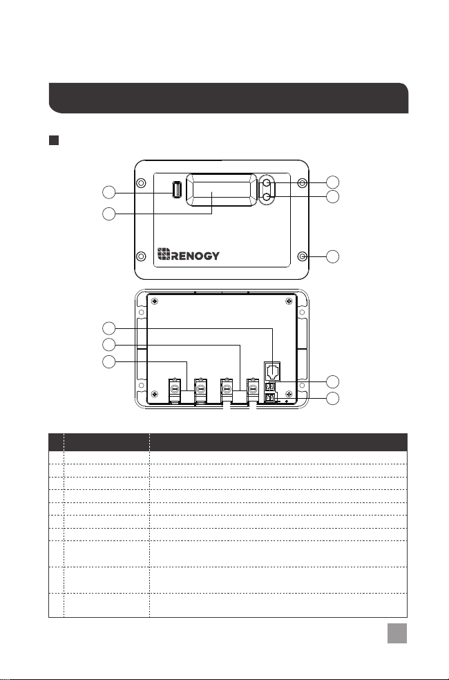
Identification of Parts
Product Overview
#
Label Description
1
2
1
4
8
7
6
2
3
5
9
10
USB Port 5V, Up to 2.4A USB port for charging USB devices.
Select Button Cycle through the interface
3
Enter Button Parameter Setting button
4
LCD Display Blue Backlit LCD displays system status information
5
Mounting Holes diameter holes for mounting the controller
6
PV Terminals Positive and Negative PV Terminals
7
Battery Terminals Positive and Negative Battery Terminals
8
RS232 Port
BVS
9
10
Temperature
Sensor Port
PV+ BATT+ BATT-
RS232
Temp.
Sensor
Batt.
Remote
PV-
EN
Battery Temperature Sensor port utilizing data for accurate
temperature compensation and charge voltage adjustment.
Battery Voltage Sensor port for measuring the battery
voltage accurately with longer line runs.
Communication port for connecting monitoring accessories
such as Bluetooth, requires a separate purchase.
06
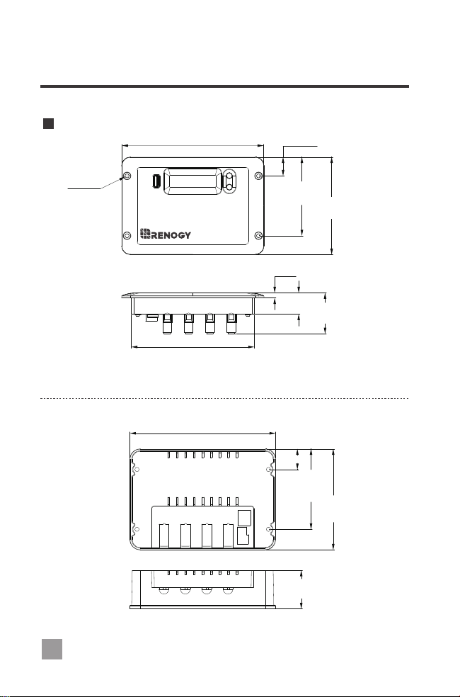
Dimensions
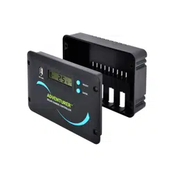
Adventurer Accessory
Adventurer Controller
165.8mm
6.5in
0.9in
3.6in
4.5in
φ4.8mm
φ0.2in
0.2in
1.0in
1.9in
5.7in
6.7in
3.7in
4.7in
1.8in
0.9in
22.1mm
92.1mm
114.2mm
47.8mm
25mm
6mm
170.6mm
118.2mm
24.1mm
94.1mm
45mm
143.9mm
EN
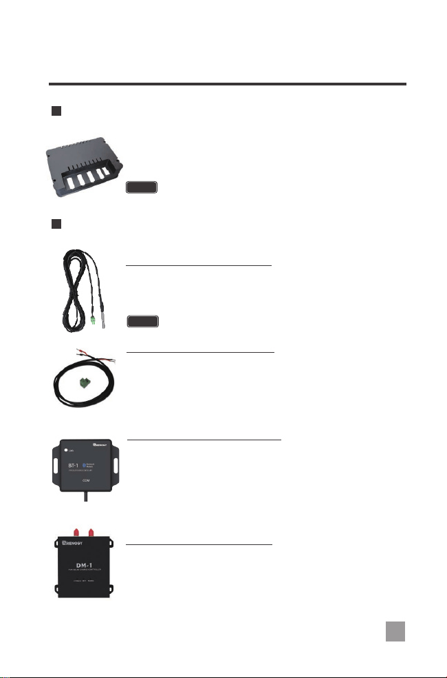
These components are not included and require a separate purchase.
Screws included for the attachment
Screws are included for flush mounting.
Included Components
Optional Components
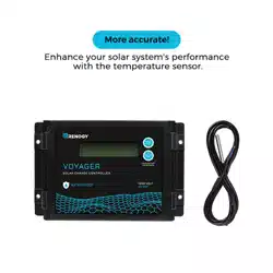
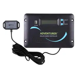
This sensor measures the temperature at the battery and uses this
data for very accurate temperature compensation. Accurate
temperature compensation is important in ensuring proper battery
charging regardless of the temperature.
NOTE
Do Not use this sensor when charging lithium battery.
Remote Temperature Sensor:
The battery voltage sensor is polarity sensitive and should be used if
the adventurer will be installed with longer line runs. In longer runs, due
to connection and cable resistance, there can be discrepancies in the
voltages at the battery terminals. The BVS will make sure the voltage is
always correct to ensure the most efficient charging.
Battery Voltage Sensor (BVS):
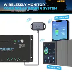
The BT-1 Bluetooth module is a great addition to any Renogy charge
controllers with a RS232 port and is used to pair charge controllers
with the Renogy BT App. After pairing is done you can monitor your
system and change parameters directly from you cell phone or tablet.
No more wondering how your system is performing, now you can see
performance in real time without the need of checking on the
controller’s LCD.
Renogy BT-1 Bluetooth Module:
The DM-1 4G Module is capable of connecting to select Renogy
charge controllers through an RS232, and is used to pair charge
controllers with Renogy 4G monitoring app. This app allows you to
conveniently monitor your system and charge syeters parameters
remotely from anywhere 4G LTE network service is available.
Renogy DM-1 4G Data Module:
07
EN
The Renogy Adventurer Surface Mount will give you the option to
mount the charge controller to any flat surface; circumventing the flush
mount option.
Adventurer Surface Mount Attachment
NOTE

Installation
Connect battery terminal wires to the charge controller FIRST then connect the
solar panel(s) to the charge controller. NEVER connect solar panel to charge
controller before the battery.
Do not over tighten the screw terminals. This could potentially break the piece
that holds the wire to the charge controller.
The Adventurer is designed for flush mounting on a wall. It consists of a face plate with
projecting terminals on the backside for connecting the battery bank, panels, and optional
sensors for accurate battery voltage sensing and battery temperature compensation. If
utilizing the wall mount, then the wall will be required to be cut to accommodate the
projecting terminals on the backside. Make sure that the pocket of the wall cut leaves
enough space to not damage the terminals when the Adventurer is being pushed back
into the cut out section of the wall.
The front of the Adventurer will serve as a heat sink, therefore it is important to ensure that
the mounting location is not near any heat generating sources and ensure that there is
proper airflow across the faceplate of the Adventurer to remove the heat dissipated from
the surface.
Refer to the technical specifications for max wire sizes on the controller and for
the maximum amperage going through wires.
Never install the controller in a sealed enclosure with flooded batteries. Gas
can accumulate and there is a risk of explosion.
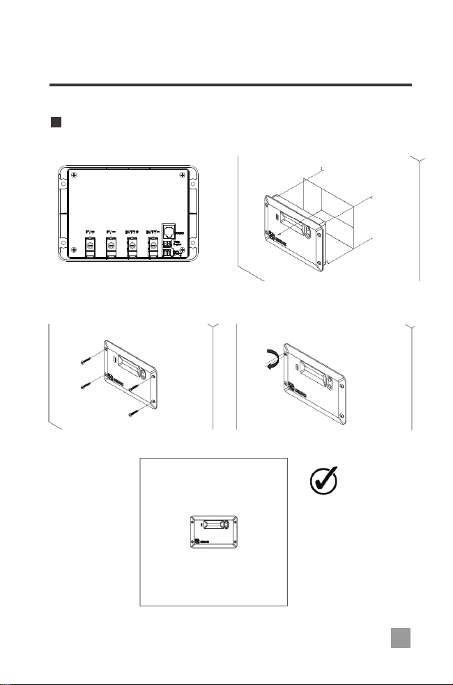
Choose Mounting Location—place the controller on a vertical surface protected from
direct sunlight, high temperatures, and water. Make sure there is good ventilation.
Check for Clearance—verify that there is sufficient room to run wires, as well as
clearance above and below the controller for ventilation. The clearance should be at
least 6 inches (150mm).
Cut out Wall section—the recommended wall size to be cut should follow the inner
protruding part of the charge controller while being careful not to go past the mounting
holes. The depth should be at least 1.7 inches (43mm).
The Adventurer comes equipped with screws for wall mounting. If they are not
suitable try using Pan Head Phillips Screw 18-8 Stainless Steel M3.9 Size
25mm length screws
NOTE
CAUTION
WARNING
WARNING
Mark Holes
Drill Holes
Secure the charge controller.
Mounting Recommendations:
1.
2.
3.
4.
5.
6.
08
EN
09
Flush Mounting:
EN
10
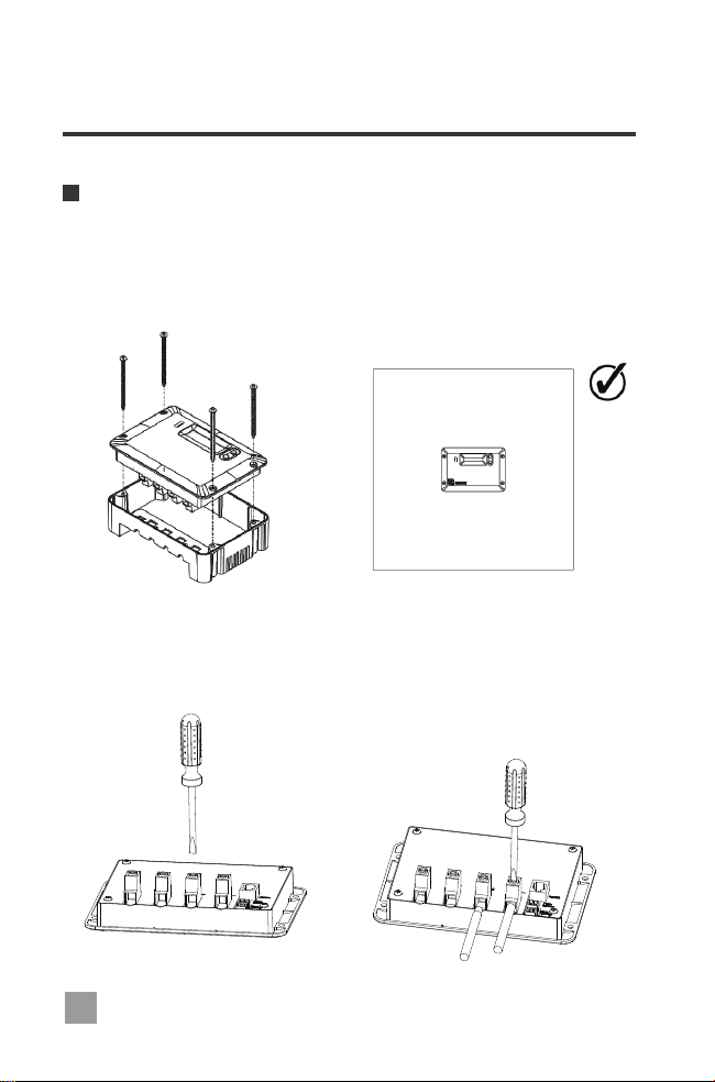
Surface Mount Attachment:
Wiring
The charge controller can also be mounted on a flat surface using the Adventurer Surface
Mount Attachment. In order to properly mount the charge controller, there is no need to
cut a section of the wall considering the charge controller can now be mounted on a flat
surface using the attachment. Mark and drill holes using the four pan head Phillips screws
that are provided specifically for the surface mount option.
1.Unscrew battery terminals by rotating counterclockwise to open the hatch. Then
connect the positive and negative battery connections in their appropriate labeled
terminal. The controller will turn on upon successful connection.
EN
11
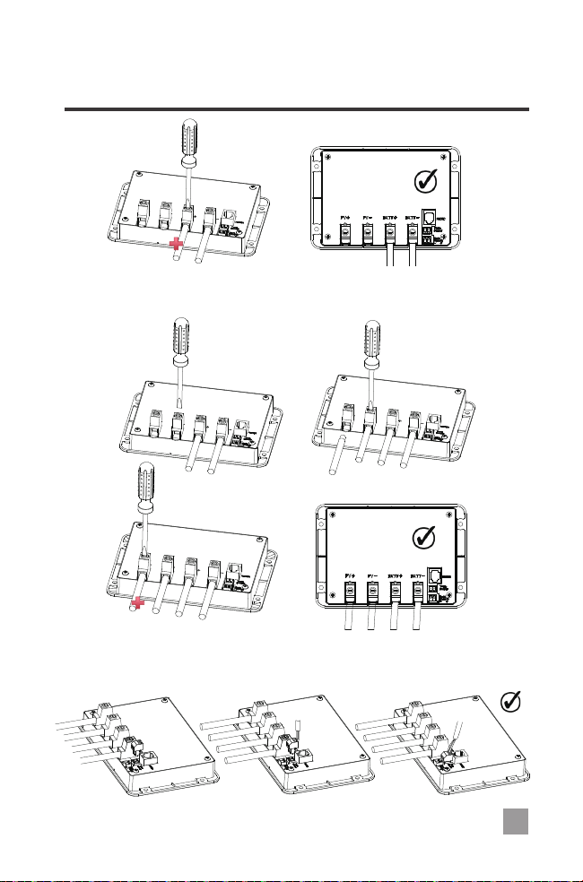
2.Unscrew PV terminals by rotating counterclockwise to open the hatch. Then connect
the positive and negative battery connections in their appropriate labeled terminal.
EN
3. Insert temperature sensor block terminal and connect wire. It is not polarity sensitive.
(Optional, requires a separate purchase).
12
If unscrewing the Battery Voltage Sensor terminal block, make sure to not mix the wires.
It is polarity sensitive and may cause damage to the controller if connected incorrectly.
WARNING
EN
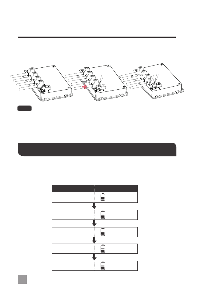
4. Insert the battery voltage sensor terminal block in the Batt Remote port. This is
polarity sensitive. (Optional, requires a separate purchase).
Operation
After connecting the battery to the charge controller, the controller will turn on
automatically. Assuming normal operation, the charge controller will cycle through
different display. They are as follows:
Parameter Display
PV Array Voltage
0.0
V
Charging Current
0.0
A
Generated Energy
0.0
kWh
Battery Voltage
0.0
V
Temperature
0.0
F
0
PV
PV
PV
BALL
BALL
13
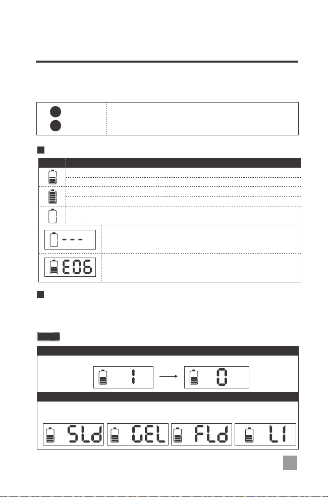
System Status Icons
Change the Parameters
Behavior
Constant: System is normal, but it is not charging.
Charging:
Constant:
The battery is at full charge.
Flashing: The battery is overvoltage.
Flashing:
The battery is under voltage.
The bars will be sequencing indicating the system is charging.
Icon
Simply hold the “ENTER” button for approximately 5 seconds until the display flashes.
Once flashing, then press “SELECT” until the desired parameter is reached and press
“ENTER” one more time to lock in the parameter.
In this interface, the user is able to select which type of battery is connected to the
charge controller. Choose from Sealed, Gel, or Flooded batteries.
The screen must be at the appropriate interface in order to change the specific parameter.
NOTE
The user is able to reset the current power generation (kWh) back to 0 kWh.
2.Battery Interface Set Battery Type
1.Power Generation Interface Reset
BATT.
TYPE
BATT.
TYPE
BATT.
TYPE
BATT.
TYPE
kWh
PV PV
AkWh
EN
The Adventurer is an easy to use controller requiring minimal maintenance. The user is
able to adjust some parameters based on the display screen. The user can manually
cycle through the display screens by using the “SELECT” and “ENTER” buttons
SELECT
Cycles forwards through the different display screens.
ENTER
Cycles backwards through the different select screens
&
Customize some parameters on the charge controller
Constant: System is abnormal.
Flashing: The bars are sequencing,indicating the controller
is activating over-discharged lithium battery.
14
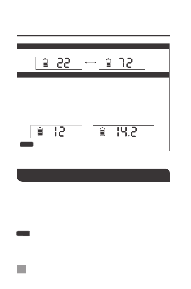
The user can select between displaying battery temperature in Celsius or Fahrenheit.
3.Battery TemperatureInterface Change from C° to F°
C
0
BATT.
F
0
BATT.
The Adventurer PWM charge controller has a reactivation feature to awaken a sleeping
lithium battery. The protection circuit of Li-ion battery will typically turn the battery off and
make it unusable if over-discharged. This can happen when storing a Li-ion pack in a
discharged state for any length of time as self-discharge would gradually deplete the
remaining charge. Without the wake-up feature to reactivate and recharge batteries,
these batteries would become unserviceable and the packs would be discarded. The
Adventurer will apply a small charge current to activate the protection circuit and if a
correct cell voltage can be reached, it starts a normal charge.
When using the Adventurer to charge a 24V lithium battery bank, set the system voltage
to 24V instead of auto recognition. Otherwise, the over-discharged 24V lithium battery
wouldn’t be activated.
NOTE
When using the Adventurer to charge lithium battery, the user is able to set Battery
Parameters. In the Battery Interface, select Lithium as Battery Type. Short press
“ENTER” to enter Battery Voltage selection interface.
Press “SELECT” to select the Battery Voltage. Press “ENTER” to confirm selection
and go to Charging Parameters Interface.
Press “SELECT” to change the Boost Voltage. The default setting is 14.2V and the
user is able to set it in the range 12.6~16.0V, with a step of 0.2V. Hold “ENTER” to
confirm the selection. The setting will also be automatically saved after 15 seconds
without holding “ENTER”.
4. Set Battery Type to Lithium Set Lithium Battery Parameters
The above settings are only available under Lithium Battery type.
CAUTION
V
12V
BATT.
V
12V
CHG
BATT.
Lithium Battery Activation
EN
15
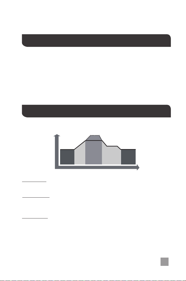
Float Charge: After Boost Charge, the controller will reduce the battery voltage to a float
voltage set point. Once the battery is fully charged, there will be no more chemical
reactions and all the charge current would turn into heat or gas. Because of this, the charge
controller will reduce the voltage charge to smaller quantity, while lightly charging the
battery. The purpose for this is to offset the power consumption while maintaining a full
battery storage capacity. In the event that a load drawn from the battery exceeds the
charge current, the controller will no longer be able to maintain the battery to a Float set
point and the controller will end the float charge stage and refer back to bulk charging.
Boost Charge:
Bulk Charge: This algorithm is used for day to day charging. It uses 100% of available
solar power to recharge the battery and is equivalent to constant current.
When the battery has charged to the Boost voltage set-point, it undergoes
an absorption stage which is equivalent to constant voltage regulation to prevent heating
and excessive gassing in the battery. The Boost time is 120 minutes.
The Adventurerhas a 4-stage battery charging algorithm for a rapid, efficient, and safe
battery charging. They include: Bulk Charge, Boost Charge, Float Charge, and Equalization.
TIME
NIGHT
BOOST
EQUALIZE
FLOAT
NIGHT
BULK
CHARGE
VOLTAGE
The Adventurer utilizes Pulse Width Modulation (PWM) technology for battery charging.
Battery charging is a current based process so controlling the current will control the
battery voltage. For the most accurate return of capacity, and for the prevention of
excessive gassing pressure, the battery is required to be controlled by specified voltage
regulation set points for Absorption, Float, and Equalization charging stages. The charge
controller uses automatic duty cycle conversion, creating pulses of current to charge the
battery. The duty cycle is proportional to the difference between the sensed battery
voltage and the specified voltage regulation set point. Once the battery reached the
specified voltage range, pulse current charging mode allows the battery to react and
allows for an acceptable rate of charge for the battery level.
PWM Technology
Four Charging Stages
EN
16
Equalization: Is carried out every 28 days of the month. It is intentional overcharging of
the battery for a controlled period of time. Certain types of batteries benefit from periodic
equalizing charge, which can stir the electrolyte, balance battery voltage and complete
chemical reaction. Equalizing charge increases the battery voltage, higher than the
standard complement voltage, which gasifies the battery electrolyte.
Once equalization is active in the battery charging, it will not exit this
stage unless there is adequate charging current from the solar panel.
There should be NO load on the batteries when in equalization
charging stage.
Over-charging and excessive gas precipitation may damage the
battery plates and activate material shedding on them. Too high of
equalizing charge or for too long may cause damage. Please carefully
review the specific requirements of the battery used in the system.
WARNING
WARNING
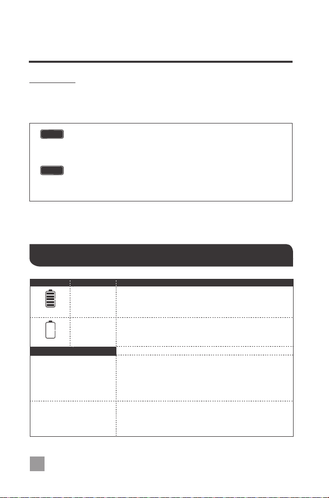
System Status Troubleshooting
Troubleshoot
Flashing
Flashing
Other Considerations
Use a multi-meter to check the voltage of the battery.
Make sure the battery voltage is not exceeding the rated
specification of the charge controller. Disconnect battery.
Confirm that there is a tight and correct connection from
the battery bank to the charge controller and the solar
panels to the charge controller. Use a multi-meter to
check if the polarity of the solar modules have been
reversed on the charge controller’s solar terminals.
Check the rated battery voltage. The LCD will not display
on the charge controller unless there is at least 9V
coming from the battery bank.
Everything is connected
correctly, but the LCD on
the controller does not
turn on
Charge controller does not
charge during daytime
when the sun is shining on
the solar panels.
Use a multi-meter to verify the rated battery voltage.
Disconnect any loads connected to the battery to allow it
to charge.
Battery over
voltage
Battery under
voltage
Indicator Description
EN

17
Error Codes
Maintenance
Fusing
1. Check that controller is mounted in a clean, dry, and ventilated area.
2. Check wiring going into the charge controller and make sure there is no wire damage or wear.
3. Tighten all terminals and inspect any loose, broken, or burnt up connections.
For best controller performance, it is recommended that these tasks be performed from
time to time.
DescriptionError Number
E0
E01
E02
E06
E07
E08
E10
E13
E14
No error detected
Battery over-discharged
Battery over-voltage
Controller over-temperature
Battery over-temperature
PV input over-current
PV over-voltage
PV reverse polarity
Battery reverse polarity
EN
AWG
16 14 12 10 8 6 4 2 0
Max. Current
55A30A20A15A10A 75A 95A
130A 170A
Parallel
Fusing is a recommendation in PV systems to provide a safety measure for connections
going from panel to controller and controller to battery. Remember to always use the
recommended wire gauge size based on the PV system and the controller.
NEC Maximum Current for different Copper Wire Sizes
Fuse from Controller to Battery
Fuse from Solar Panel(s) to Controller
Ex. 200W; 2 X 100 W panels
Ex. Adventurer = 30A fuse from Controller to Battery
Controller to Battery Fuse = Current Rating of Charge Controller
Fuse = minimum of 11.5 * 1.25 = 14.38= 15A fuse
Total Amperage = Isc1 + Isc2 = (5.75A + 5.75A) * 1.25
18
Technical Specifications
Battery Charging Parameters
Description
Nominal Voltage
30A
Battery GEL SLD/ AGM FLOODED
High Voltage Disconnect 16 V 16 V 16 V
Charging Limit Voltage 15.5 V 15.5 V15.5 V
Boost Voltage
Float Voltage
Boost Return Voltage
Under Voltage Recover
Over Voltage Reconnect
Under Voltage Warning
Low Voltage Reconnect
Parameter
Rated Charge Current
12V/24V Auto Recognition
15 V 15 V 15 V
5V, 2.4A max
Max. PV Input Voltage
USB Output
Operating Temperature
Storage Temperature
Enclosure
Terminals
Weight
Dimensions
IP20
Up to # 8AWG
Equalization Voltage ----- ----- -----
-----
14.8 V
14.2 V 14.6 V 14.6 V
13.8 V 13.8 V 13.8 V
13.2 V13.2 V13.2 V
12.6 V
12.2 V
11.1 V
10.8 V 10.8 V 10.8 V
11.1 V 11.1 V
12V
12.6 V
12.2 V
12V
12.6 V
12.2 V
12V
Equalization Duration
----- ----- -----
-----
2 hours
2 hours2 hours 2 hours
LITHIUM
16 V
15.5 V
15 V
13.2 V
10.8 V
11.1 V
12.6 V
12.2 V
12V
Boost Duration
Self-consumption
Temperature Compensation Coefficient
50 VDC
0.6 lbs / 272g
RS232
Sealed (AGM), Gel, Flooded, and Lithium
6.56 x 4.50 x 1.90 in / 167 x 114 x 48 mm
-35℃ to +80℃ | -31
o
F to 176
o
F
-25℃ to +55℃ | -13
o
F to 131
o
F
-3mV/℃/2V
≤13mA
Low Voltage Disconnect
Discharging Limit Voltage
Communication
Battery Type
14.2 V
(User: 12.6-16 V)
EN

Renogy reserves the right to change
the contents of this manual without notice.
RENOGY.COM
US
2775 E Philadelphia St, Ontario, CA 91761, USA
909-287-7111
www.renogy.com
customerservice@renogy.com
https://www.renogy.cn
sales@renogy.cn
CN
400-6636-695
苏州高新区科技城培源路1号5号楼-4
CA
https://ca.renogy.com
onlinestoreca@renogy.com
https://au.renogy.com
onlinestoreau@renogy.com
AU
JP
https://www.renogy.jp
onlinestorejp@renogy.com
https://uk.renogy.com
onlinestoreuk@renogy.com
UK
https://de.renogy.com
onlinestorede@renogy.com
DE
https://fr.renogy.com
onlinestorefr@renogy.com
FR