
Programmable DC Power
Supply
IT6900 Series User Manual
Model: IT6922A/IT6932A/IT6933A/IT6942A/
IT6952A/IT6953A/IT6922B/
IT6932B/IT6942B/IT6952B/IT6953B
Version: V2.0

Statement
© Itech Electronic, Co., Ltd. 2018
No part of this manual may be
reproduced in any form or by any means
(including electronic storage and
retrieval or translation into a foreign
language) without prior permission and
written consent from Itech Electronic,
Co., Ltd. as governed by international
copyright laws.
Manual Article No.
IT6900-402178
Revision
Revision 2, published on
Aug. 31st 2018
Itech Electronic, Co., Ltd.
Trademark Statement
Pentium is a registered trademark of
Intel Corporation in the United States.
Microsoft, Visual Studio, Windows and
MS Windows are trademarks of
Microsoft Corporation in the United
States and/or other countries/regions.
Guarantee
Materials in the document are provided
talis qualis and may be changed in
future revisions without prior notice. In
addition, within the maximum allowable
extent of laws, ITECH is not committed
to any explicit or implied guarantee for
this manual and all information therein,
including but not limited to the implied
guarantee on marketability and
availability for some special purposes.
ITECH shall not be responsible for any
error or incidental or indirect losses
caused by the provision, use or
application of this documents and
information therein. If some guarantee
clauses in other written agreements
between ITECH and users are not
consistent with clauses herein, those
clauses in other written agreements
shall prevail.
Technology license
Hardware and/or software in this
document cannot be provided without a
license and can only be used or copied
according to the license.
Restricted permission statement
Restricted permissions of the U.S.
government. Permissions for software
and technical data which are authorized
to the U.S. Government only include
those for custom provision to end users.
ITECH follows FAR 12.211 (technical
data), 12.212 (computer software).
DFARS 252.227-7015 (technical
data--commercial products) for national
defense and DFARS 227.7202-3
(permissions for commercial computer
software or computer software
documents) while providing the
customized business licenses of
software and technical data.
Safety Statement
“Caution” signs indicate danger. It is
required to pay attention to the contents
of these signs during implementation of
operations.
The damage to the product or loss of
important data may be caused in case of
improper operation steps or failure to
follow operation steps. Do not continue
to implement any improper operation
indicated in “Caution” signs when the
specified conditions are not fully
understood or these conditions are not
satisfied.
“Warning” indicates danger. It is required
to pay attention to the contents of these
signs during implementation of
operation steps. Personal casualties
may be caused in case of improper
operation steps or failure to follow these
operation steps. Do not continue to
implement any improper operation
indicated in “Warning” signs when the
specified conditions are not fully
understood or these conditions are not
satisfied.
Note
“Instructions” indicates operation
instructions. It is required to refer to the
contents of these signs during operation
steps. These signs are used for
providing tips or supplementary
information for operators.
IT6900 User Manual
Copyright ©ITECH Electronic Co., Ltd. i
Certification and Quality Assurance
IT6900 series power supply completely reaches nominal technical indicators in
the manual.
Warranty Service
ITECH Company will provide one-year warranty services for the product
materials and manufacturing (excluding the following limitations).
When warranty service or repair is needed, please send the product to the
service unit specified by ITECH Company.
When the product is sent to ITECH Company for warranty service, the
customer must pay the one-way freight to the maintenance department of
ITECH, and ITECH will be responsible for return freight.
If the product is sent to ITECH for warranty service from other countries,
the customer will be responsible for all the freight, duties and other taxes.
Limitation of Warranty
This Warranty will be rendered invalid in case of the following:
Damage caused by circuit installed by customer or using customer own
products or accessories;
Product which has been modified or repaired by the customer;
Damage caused by circuit installed by customer or not operating our
products under designated environment;
The product model or serial number is altered, deleted, removed or made
illegible by customer;
Damage caused by accidents, including but not limited to lightning, water,
fire, abuse or negligence.
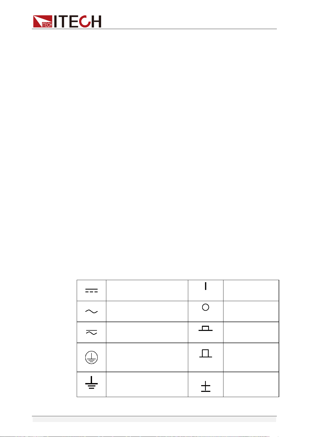
Safety Signs
Direct current
ON (power)
Alternating current
OFF (power)
Both direct and alternating
current
Power-on state
Protective earth (ground)
terminal
Power-off state
Earth (ground) terminal
Reference terminal

IT6900 User Manual
Copyright ©ITECH Electronic Co., Ltd. ii
Caution
Positive terminal
Warning (refer to this manual
for specific Warning or
Caution information)
Negative terminal
A chassis terminal
-
-
Safety Precautions
General safety precautions below must be followed in each phase of instrument
operation. In case of failure to follow these precautions or specific warnings in
other parts of the manual, violation against the safety standards related to the
design, manufacture and purpose of the instrument will occur. If the user does
not follow these precautions, ITECH will bear no responsibility arising there
from.
The power supply is provided with a three-core power cord during delivery
and should be connected to a three-core junction box. Before operation, be
sure that the power supply is well grounded.
Use electric wires of appropriate load. All loading wires should be capable
of bearing maximum short-circuit of electronic load without overheating.
Ensure the voltage fluctuation of mains supply is less than 10% of the
working voltage range in order to reduce risks of fire and electric shock.
To prevent burnout, please pay special attention to positive and negative
polarities of power supply during connection!
Do not use damaged equipment. Please check the housing before using
the equipment. Check whether the instrument is subject to cracking or is
lack of plastic. Do not operate the instrument in the environment with
explosive gas, steam or dust.
Observe all tags on the equipment before connection.
Do not install alternative parts on the instrument or perform any
unauthorized modification.
Do not use the equipment when the removable cover is dismantled or
loose.
Please use the power adapter supplied by the manufacturer to avoid
accidental injury.
We do not accept responsibility for any direct or indirect financial damage
or loss of profit that might occur when using the instrument.
This instrument is used for industrial purposes. Do not apply this product to
IT power supply system.
Do not use the equipment on the life support system or other equipment
with safety requirements.
IT6900 User Manual
Copyright ©ITECH Electronic Co., Ltd. iii
If the equipment is not used in the manner specified by the manufacturer,
its protection may be damaged.
Always use dry cloth to clean the equipment housing. Do not clean the
inside of the instrument.
Do not block the air vent of the equipment.
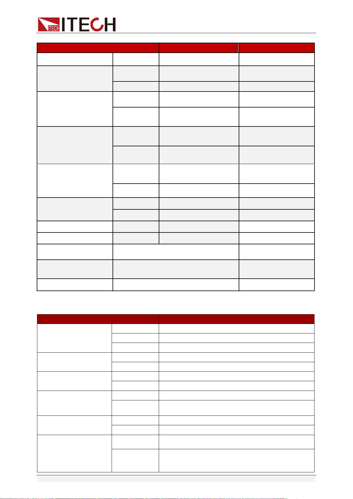
Environmental Conditions
The IT6900 series power supply can only be used indoors or in low
condensation areas. The following table shows general environmental
requirements for this instrument.
Environmental conditions
Requirement
Operating temperature
0°C - 40°C
Operating humidity
20% - 80% (non condensing)
Storage temperature
-20°C - 70 °C
Altitude
Operating up to 2,000 meters
Pollution
Grade 2 pollution
Installation category
Ⅱ
Note
To make accurate measurements, allow the instrument to warm up for 30 min before
operation.
Regulation Tag
The CE mark indicates that the product
complies with all the relevant European
legal directives. The specific year (if any)
affixed refers to the year when the design
was approved.
The instrument complies with the WEEE
Directive (2002/96/EC) marking
requirement. This affixed product label
indicates that you must not discard the
electrical/electronic product in domestic
household waste.

IT6900 User Manual
Copyright ©ITECH Electronic Co., Ltd. iv
This symbol indicates the time period
during which no hazardous or toxic
substances are expected to leak or
deteriorate during normal use. The
expected service life of the product is 10
years. The product can be used safely
during the 10-year Environment Friendly
Use Period (EFUP). Upon expiration of the
EFUP, the product must be immediately
recycled.
Waste Electrical and Electronic Equipment (WEEE)
Directive
Waste electrical and electronic equipment (WEEE) directive,
2002/96/EC
The product complies with tag requirements of the WEEE directive
(2002/96/EC). This tag indicates that the electronic equipment
cannot be disposed of as ordinary household waste.
Product Category
According to the equipment classification in Annex I of the WEEE
directive, this instrument belongs to the “Monitoring” product.
If you want to return the unnecessary instrument, please contact
the nearest sales office of ITECH.

IT6900 User Manual
Copyright ©ITECH Electronic Co., Ltd. v
Compliance Information
Complies with the essential requirements of the following applicable European
Directives, and carries the CE marking accordingly:
Electromagnetic Compatibility (EMC) Directive 2014/30/EU
Low-Voltage Directive (Safety) 2014/35/EU
Conforms with the following product standards:
EMC Standard
IEC 61326-1:2012/ EN 61326-1:2013 ¹²³
Reference Standards
CISPR 11:2009+A1:2010/ EN 55011:2009+A1:2010 (Group 1, Class A)
IEC 61000-4-2:2008/ EN 61000-4-2:2009
IEC 61000-4-3:2006+A1:2007+A2:2010/ EN 61000-4-3:2006+A1:2008+A2:2010
IEC 61000-4-4:2004+A1:2010/ EN 61000-4-4:2004+A1:2010
IEC 61000-4-5:2005/ EN 61000-4-5:2006
IEC 61000-4-6:2008/ EN 61000-4-6:2009
IEC 61000-4-11:2004/ EN 61000-4-11:2004
1. The product is intended for use in non-residential/non-domestic environments. Use of the
product in residential/domestic environments may cause electromagnetic interference.
2. Connection of the instrument to a test object may produce radiations beyond the specified
limit.
3. Use high-performance shielded interface cable to ensure conformity with the EMC standards
listed above.
Safety Standard
IEC 61010-1:2010/ EN 61010-1:2010

IT6900 User Manual
Copyright ©ITECH Electronic Co., Ltd. vi
Content
Certification and Quality Assurance ........................................................................................................... i
Warranty Service ........................................................................................................................................ i
Limitation of Warranty ................................................................................................................................. i
Safety Signs................................................................................................................................................ i
Safety Precautions ..................................................................................................................................... ii
Environmental Conditions .......................................................................................................................... iii
Regulation Tag ........................................................................................................................................... iii
Waste Electrical and Electronic Equipment (WEEE) Directive .................................................................. iv
Compliance Information ............................................................................................................................. v
Chapter1 Inspection and Installation .................................................................................................. 1
1.1 Verifying the Shipment ......................................................................................................................... 1
1.2 Instrument Size Introduction ................................................................................................................ 2
1.3 Rack Mounting ..................................................................................................................................... 3
1.4 Connecting the Power Cord ................................................................................................................ 3
Chapter2 Quick Start............................................................................................................................. 5
2.1 Brief Introduction ................................................................................................................................. 5
2.2 Introduction to front panel .................................................................................................................... 6
2.3 Key introduction ................................................................................................................................... 7
2.4 VFD Description .................................................................................................................................. 7
2.5 Introduction to rear panel ..................................................................................................................... 8
2.6 Power-on self-test .............................................................................................................................. 10
Chapter3 Function and Features ....................................................................................................... 13
3.1 Local/Remote Mode .......................................................................................................................... 13
3.2 Voltage Setup .................................................................................................................................... 13
3.3 Current Setup .................................................................................................................................... 13
3.4 On/Off Operation ............................................................................................................................... 14
3.5 Setup value/Actual value ................................................................................................................... 14
3.6 Voltage/Current/Power adjustment .................................................................................................... 14
3.7 Saving Operation ............................................................................................................................... 14
3.8 Trigger operation ............................................................................................................................... 15
3.9 Menu operation .................................................................................................................................. 15
3.10 OVP Function .................................................................................................................................. 23
3.11 Key Lock .......................................................................................................................................... 23
3.12 Rear pins function ............................................................................................................................ 24
3.12.1 Remote sense and DVM terminals ........................................................................................... 24
3.12.2 RS485 and Output Sync signal interface .................................................................................. 25
3.13 Analog control interface ................................................................................................................... 26
Chapter4 Remote Operation Mode .................................................................................................... 27
4.1 RS232 interface ................................................................................................................................. 27
4.2 USB interface .................................................................................................................................... 29
4.3 GPIB interface ................................................................................................................................... 29
4.4 RS485 interface ................................................................................................................................. 29

IT6900 User Manual
Copyright ©ITECH Electronic Co., Ltd. vii
Chapter5 Technical Specification ...................................................................................................... 31
5.1 Major Technical Parameters .............................................................................................................. 31
5.2 Supplemental Characteristics ............................................................................................................ 36
Appendix .................................................................................................................................................... 37
Specifications of Red and Black Test Lines ............................................................................................. 37
Inspection and Installation
Copyright ©ITECH Electronic Co., Ltd. 1
Chapter1 Inspection and Installation
1.1 Verifying the Shipment
Unpack the box and check the contents before operating the instrument. If
wrong items have been delivered, if items are missing, or if there is a defect
with the appearance of the items, contact the dealer from which you purchased
the instrument immediately. The package contents include:
Checklist of Package Contents
Item
Qty.
Model
Remarks
IT6900 power
supply
x1
IT6900 series
The IT6900 series include:
IT6922A/IT6932A/IT6933A/
IT6942A/IT6952A/IT6953A/
IT6922B/IT6932B/IT6942B/
IT6952B/IT6953B
Power cord
x1
IT-E171/IT-E172
/IT-E173/IT-E17
4
User may select an appropriate
power cord that matches the
specifications of power socket
used in the area. See the Section
Connecting the Power Cord for
details.
USB cable
x1
-
-
CD
x1
-
It contains IT6900 power supply
User’s Manual, Programming
Guide and other user
documentations.
Ex-factory Test
Report
x1
-
It is the test report of the
instrument before delivery.
NOTE
After confirming that package contents are consistent and correct, please appropriately
keep package box and related contents. The package requirements should be met when
the instrument is returned to factory for repair.
IT6900 series power supply is supplied with the following optional accessories
(sold separately):
Item
Model
Remarks
IT-E151A (Rack
mount kit)
IT-E151A
To mount the instrument on a special rack,
user may select this optional.
Inspection and Installation
Copyright ©ITECH Electronic Co., Ltd. 2
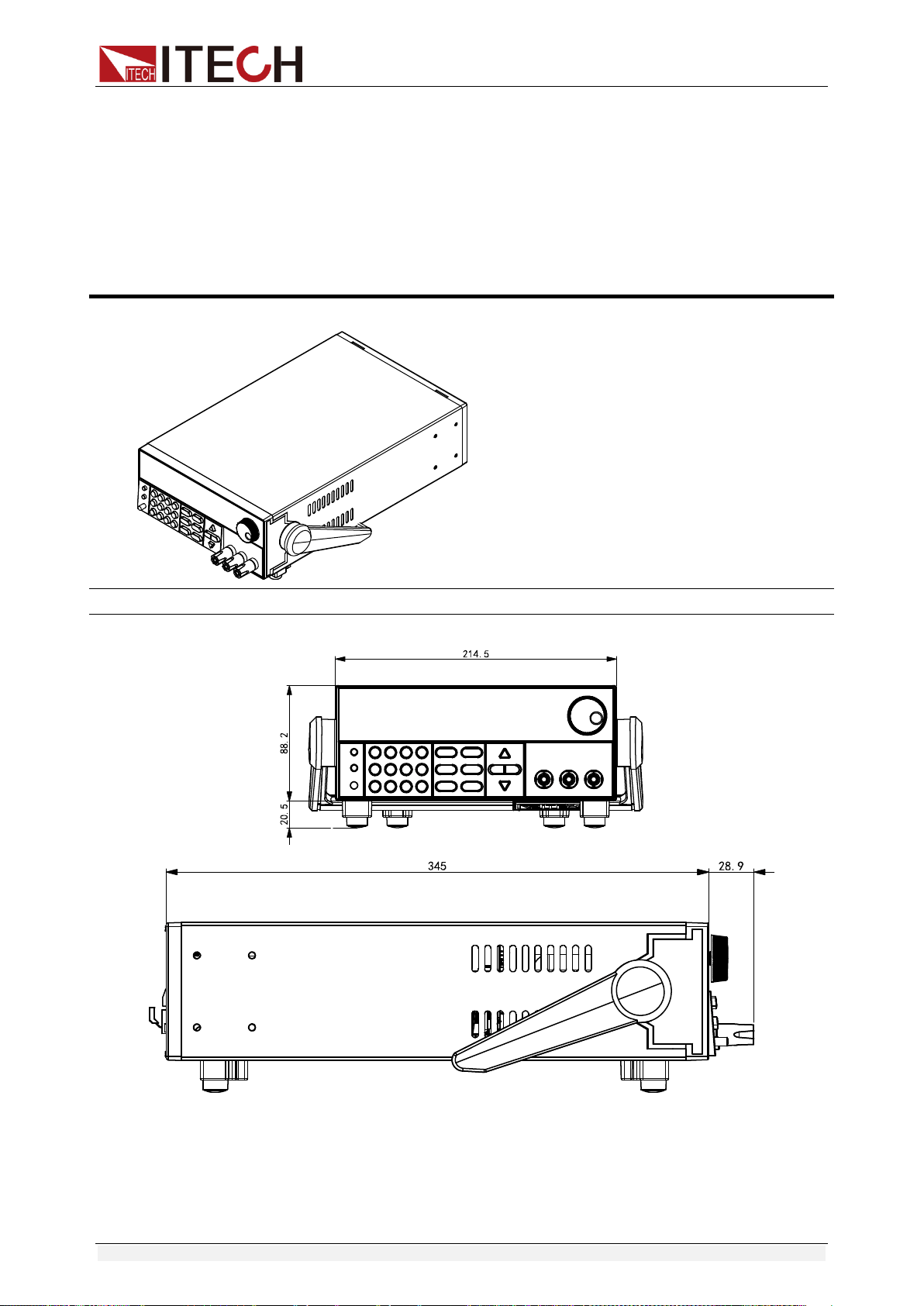
1.2 Instrument Size Introduction
The instrument should be installed at well-ventilated and rational-sized space.
Please select appropriate space for installation based on the electronic load
size.
IT6900 series power supply different models are not the same size, the detail
size of the power supply is shown as below.
IT6922A/IT6932A/IT6933A/IT6942A/IT6922B/IT6932B/IT6942B Models
Detailed Dimension Drawing
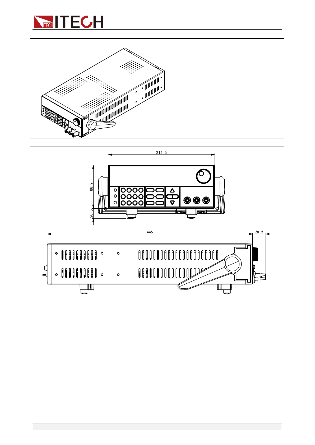
Inspection and Installation
Copyright ©ITECH Electronic Co., Ltd. 3
IT6952A/IT6953A/IT6952B/IT6953B Models
Detailed Dimension Drawing
1.3 Rack Mounting
IT6900 series power supply can be mounted on a standard 19” rack. ITECH
provides user with IT-E151A rack, an optional mount kit.
1.4 Connecting the Power Cord
Connect power cord of standard accessories and ensure that the power is
under normal power supply.
AC power input level
Working voltage of IT6900 series includes 110V and 220V (which can be

Inspection and Installation
Copyright ©ITECH Electronic Co., Ltd. 4
selected by the switch at the bottom of power supply).
AC power input level:
Option Opt.01: 220VAC ± 10%, 47 to 63 Hz
Option Opt.02: 110 VAC ± 10%, 47 to 63 Hz
Categories of power lines
Select from the flowing schedule of power cord specifications an appropriate
power cord that matches the voltage for the area in which you use the
instrument. If the power cord included in the instrument you purchased does
not match the voltage, contact the dealer or manufacturer for change.
China
IT-E171
United States &
Canada & Japan
IT-E172
Europe
IT-E173
England
IT-E174

Quick Start
Copyright ©ITECH Electronic Co., Ltd. 5
Chapter2 Quick Start
This chapter introduces the front panel, the rear panel, key functions and VFD
display function of the power supply, make sure that you can quickly know the
appearance, instruction and the key function before you operate the power
supply. Help you make better use of this series of power supply.
2.1 Brief Introduction
IT6900 series power supplies are high performance single-output
programmable DC power supplied with communication interface. This series of
programmable DC power supply can output the maximum voltage or current
with a fixed power for customers. Take IT6922A (60V/5A/100W) for example,
when you select 60V for the output voltage, the output power of IT6922A is
100W, so in this case the maximum output current is 100W/60V = 1.66A. When
you select 20V for the output voltage, the maximum output current 100W/20V =
5A, but when the output voltage is down to 10V, due to IT6922A maximum
current is 5A, so in this case the maximum output current is 5A. IT6900 series
power comes with a standard communication interface
RS232/USB/GPIB/RS485, both desktop and system-based features, can be
designed and tested according to your needs and provide multi-purpose
solutions.
Convenient bench-top features:
High visibility vacuum fluorescent display (VFD)
Digital keyboard operation
High accuracy and high resolution
Low ripple and low noise
Intelligent fan control, energy conservation, noise reduction
Standard communication interface RS232/USB/GPIB/RS485
Can be monitored by computer software
Output voltage and current values accordance with procedure
Can use the knob to adjust the voltage and current
Can adjust the numbers steps using the cursor
Rich SCPI orders to facilitate the formation of intelligent test platform
Can set the output timer (0.1 ~ 99999.9s)
External Analog Control Interface
Model
Voltage
Current
Power
IT6922A
60V
5A
100W
IT6932A
60V
10A
200W
Quick Start
Copyright ©ITECH Electronic Co., Ltd. 6
IT6933A
150V
5A
200W
IT6942A
60V
15A
360W
IT6952A
60V
25A
600W
IT6953A
150V
10A
600W
IT6922B
60V
5A
100W
IT6932B
60V
10A
200W
IT6942B
60V
15A
360W
IT6952B
60V
25A
600W
IT6953B
150V
10A
600W
*IT6922B/IT6932B/IT6942B/IT6952B/IT6953B have standard RS485
communication interface and external Analog control Interface.
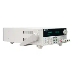
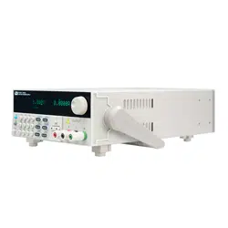
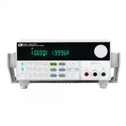
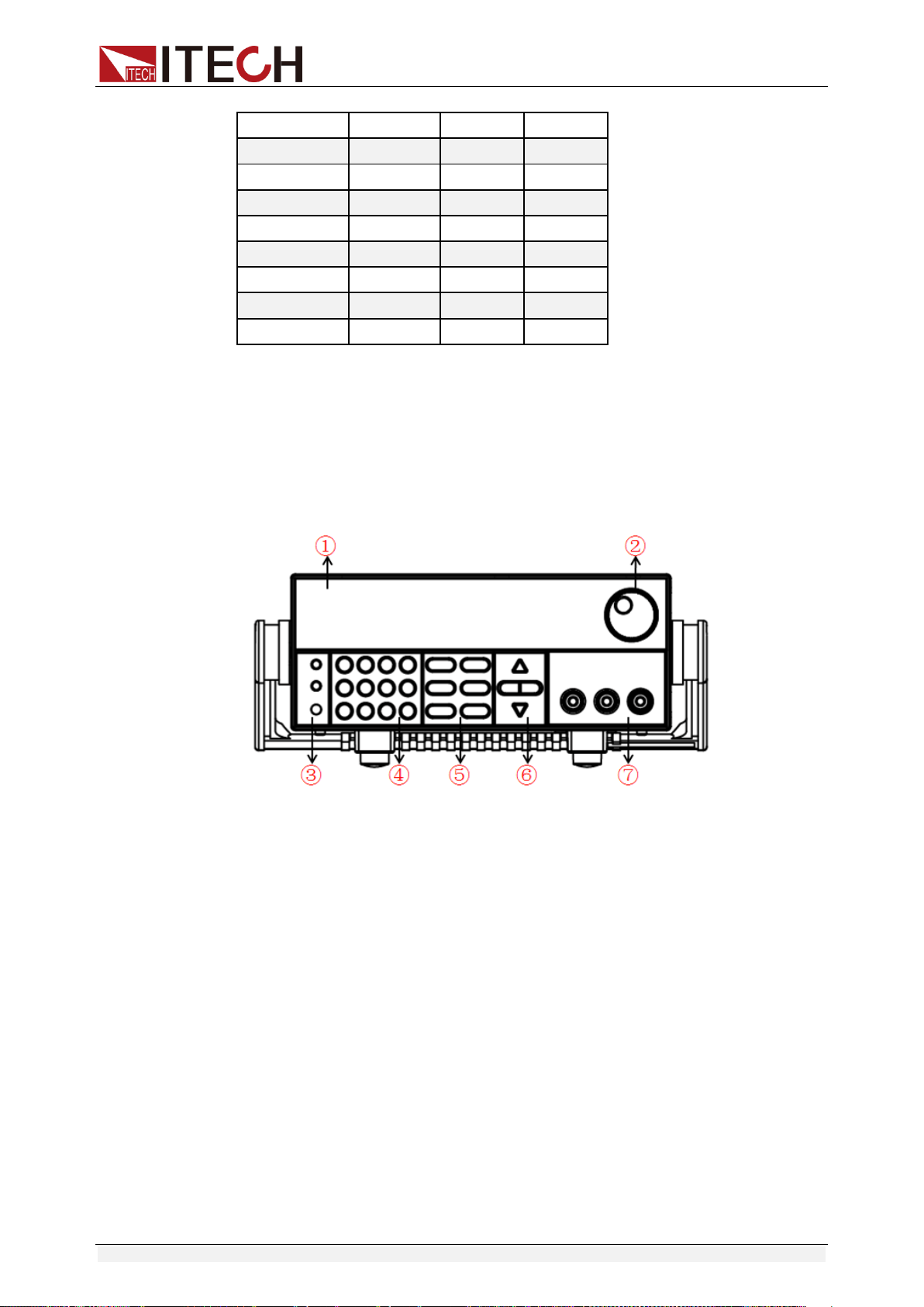
2.2 Introduction to Front Panel
The front panel of IT6900 series is shown in the next figure.
1. VFD display
2. Rotary knob
3. Compound key, the local switch key and power switch
4. Number keys and ESC
5. Function keys
6. UP/DOWN/LEFT and RIGHT key, to move cursor
7. Output terminals
Quick Start
Copyright ©ITECH Electronic Co., Ltd. 7
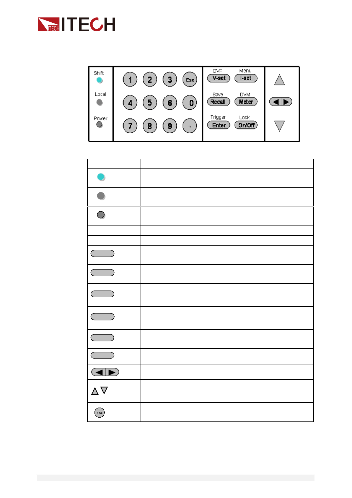
2.3 Key Introduction
Key description, see the table below:
Keys
Name and the function
(Shift)
Compound key, co-work with OVP, Menu, Save, DVM,
Trigger, Lock
(Local)
Local switch key, switch from remote mode to local
operation mode.
(Power)
Power on key
0-9
Numeric keys
.
Decimal point
V-setV-set
/OVP
Voltage set key, set the output voltage/over voltage
protection point for the power supply.
I-setI-set
/Menu
Current set key, set the output current/menu function key,
to set the relevant Parameters for the power supply.
Recall
/Save
Callback key to call up a set value of system parameters
already stored / storage key, to save system parameter
settings.
MeterMeter
/DVM
Meter key, to switch from value set panel and the actual
output value display / voltage meter function keys, to
switch to the measure state of the voltage meter.
EnterEnter
/Trigger
Enter key, to confirm the number entered and operation /
trigger button, which is used to trigger the List test.
On/Off
/Lock
Output on (off) keys, control power output state / keypad
lock function keys, used to lock the panel buttons.
Left and right movement keys, used to set the value, to
adjust the cursor to the specified location.
Up and down keys, used to select a item in the menu or
increase (decrease) the output voltage or current
values.
Cancel /return keys.
2.4 VFD Description
Quick Start
Copyright ©ITECH Electronic Co., Ltd. 8
Char
Function description
Char
Function description
OFF
Output is off
Timer
Output on timer function is ON
CV
The power supply is in
constant voltage mode
Sense
No
CC
The power supply is in
constant current mode
Ext
No
*
No
Adrs
(USB GPIB) light when the
address match or (RS232)
received order
Meter
“Meter” on state
Rmt
The power supply is in remote
mode
Shift
Use compound keys
Error
The power supply has error or
fault
OVP
OVP function state on
Prot
OVP OTP Protection
OCP
No
Lock
Key operation is locked by
Password
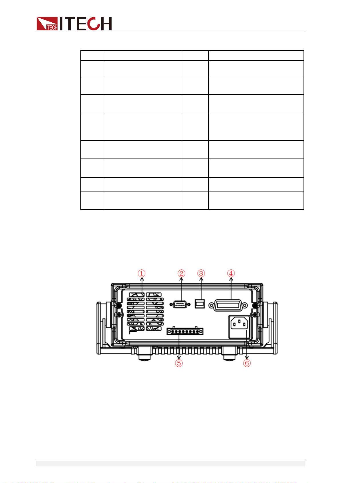
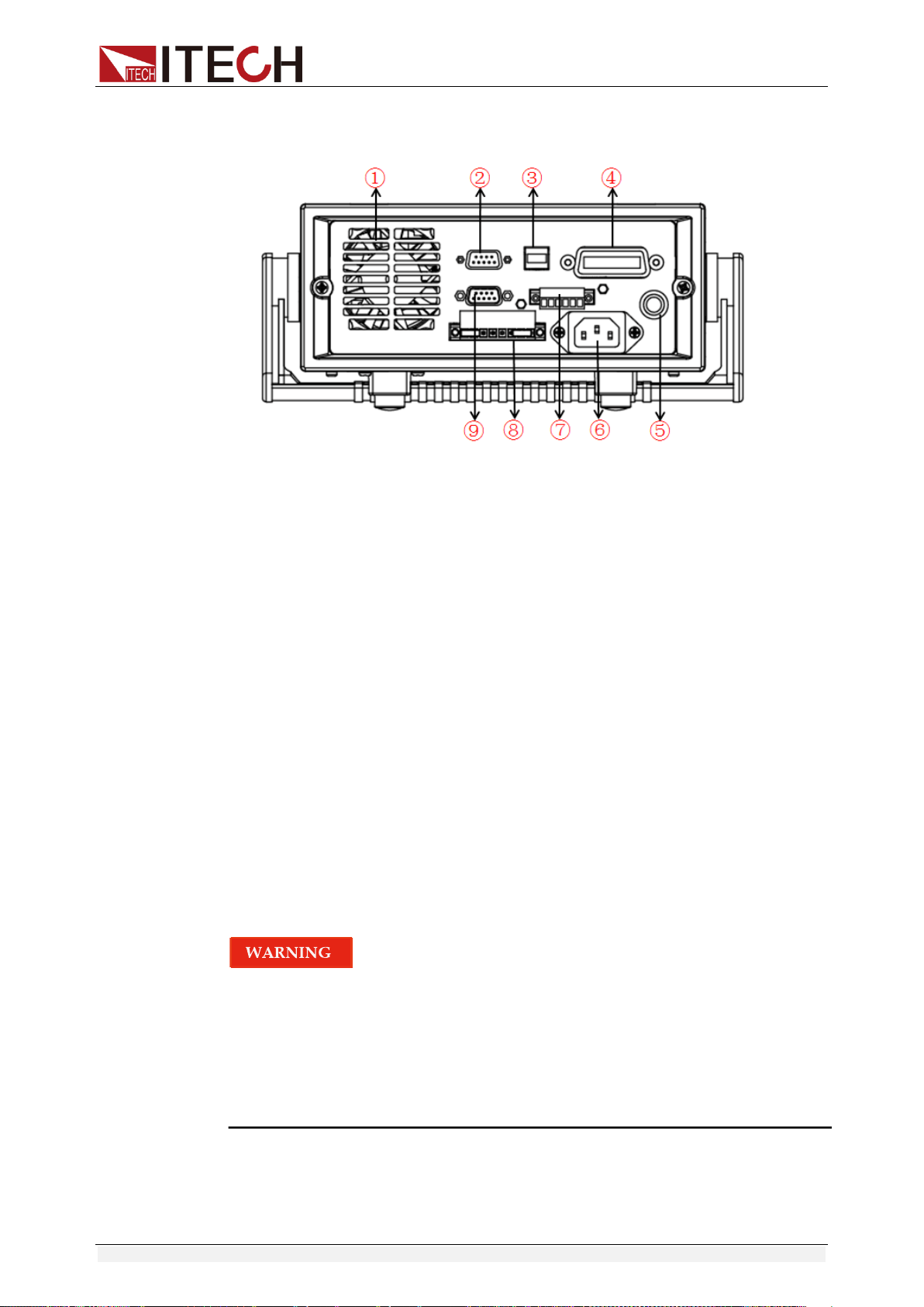
2.5 Introduction to Rear Panel
The rear panel of IT6922A/IT6932A/IT6933A/IT6942A is shown in the next
figure.
1. Cooling window
2. RS232 Communication cable interface
3. USB Communication cable interface
4. GPIB Communication cable interface
5. DVM input terminal, Remote measurement terminal and the output
terminal
6. AC power socket(fuse contained)
Quick Start
Copyright ©ITECH Electronic Co., Ltd. 9
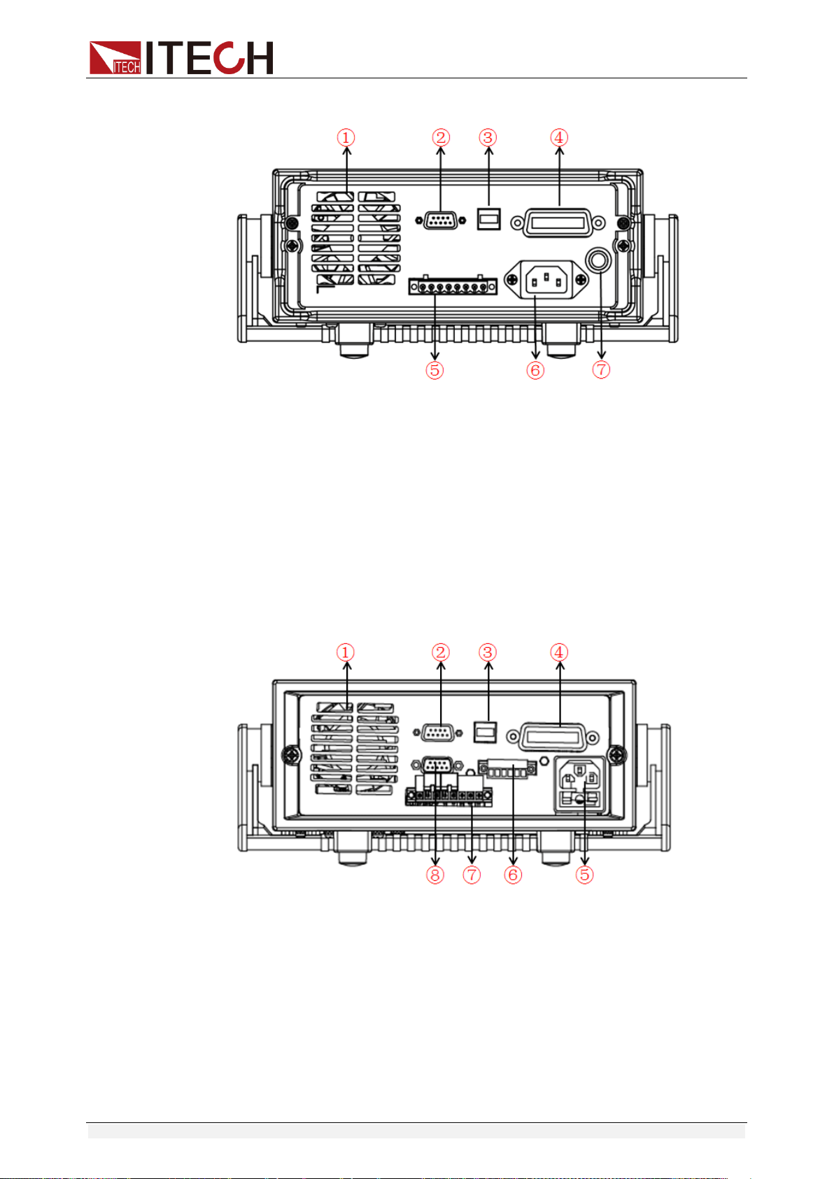
The rear panel of IT6952A/IT6953A is shown in the next figure.
1. Cooling window
2. RS232 Communication cable interface
3. USB Communication cable interface
4. GPIB Communication cable interface
5. DVM input terminal, Remote measurement terminal and the output
terminal
6. AC power socket
7. Fuse
The rear panel of IT6922B/IT6932B/IT6942B is shown in the next figure.
1. Cooling window
2. RS232 Communication cable interface
3. USB Communication cable interface
4. GPIB Communication cable interface
5. AC power socket(fuse contained)
6. Output Sync signal interface and RS485 Communication cable
interface
7. DVM input terminal, Remote measurement terminal and the output
terminal
8. Analog control interface
Quick Start
Copyright ©ITECH Electronic Co., Ltd. 10
The rear panel of IT6952B/IT6953B is shown in the next figure.
1. Cooling window
2. RS232 Communication cable interface
3. USB Communication cable interface
4. GPIB Communication cable interface
5. Fuse
6. AC power socket
7. Output Sync signal interface and RS485 Communication cable
interface
8. DVM input terminal, Remote measurement terminal and the output
terminal
9. Analog control interface
2.6 Power-on Self-test
A successful self-test indicates that the purchased power product meets
delivery standards and is available for normal usage.
Before operation, please confirm that you have fully understood the safety
instructions.
To avoid burning out, be sure to confirm that power voltage matches with
supply voltage.
Be sure to connect the main power socket to the power outlet of protective
grounding. Do not use terminal board without protective grounding. Before
operation, be sure that the power supply is well grounded.
To avoid burning out, pay attention to marks of positive and negative
polarities before wiring.
Self-test steps
Normal self-test procedures:
Quick Start
Copyright ©ITECH Electronic Co., Ltd. 11
1. Correctly connect the power cord. Press Power key to start up.
2. After self-test, if the power supply is normal, then VFD will display the
output voltage and current status as below:
Error Information References
The following error information may occur when an error occurs during Power
On self-test:
If the EEPROM was damaged or the latest operation data in EEPROM was
lost, the VFD will display “EEPROM FAIL”.
If the last power status in EEPROM is lost, then the VFD will display “SYST
LOST”.
If the calibration data in EEPROM is lost, the VFD display the tooltip
information “CAL LOST”.
If the factory calibration data in EEPROM is lost, and then the VFD will
display “FACT LOST”.
Exception handling
If the power supply cannot start normally, please check and take measures by
reference to steps below.
1. Check whether the power cord is correctly connected and confirm whether
the power supply is powered.
Correct wiring of power cord => 2
Incorrect wiring of power cord => Re-connect the power cord and check
whether the exception is removed.
2. Check whether the power in On. Power key is under “ ” On status.
Yes => 3
No => Please check the Power key to start power and check whether the
exception is removed.
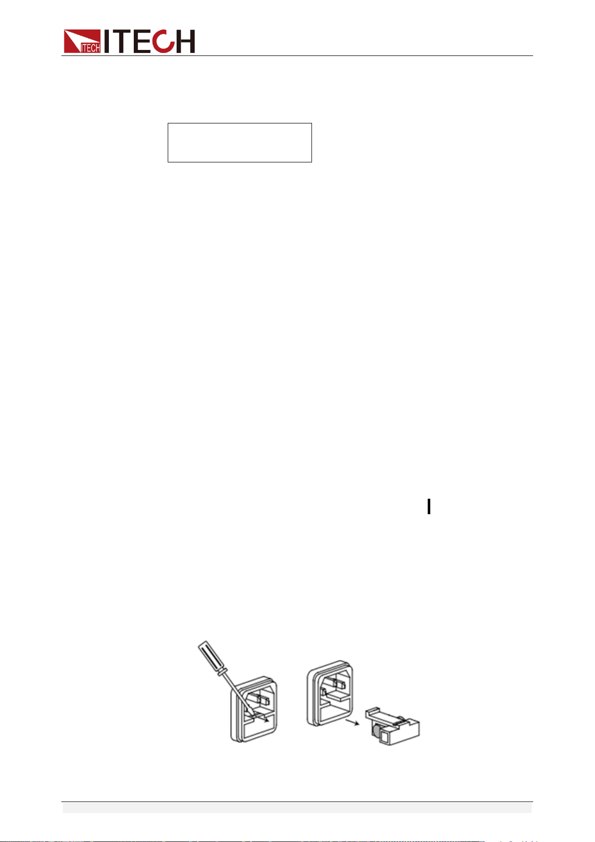
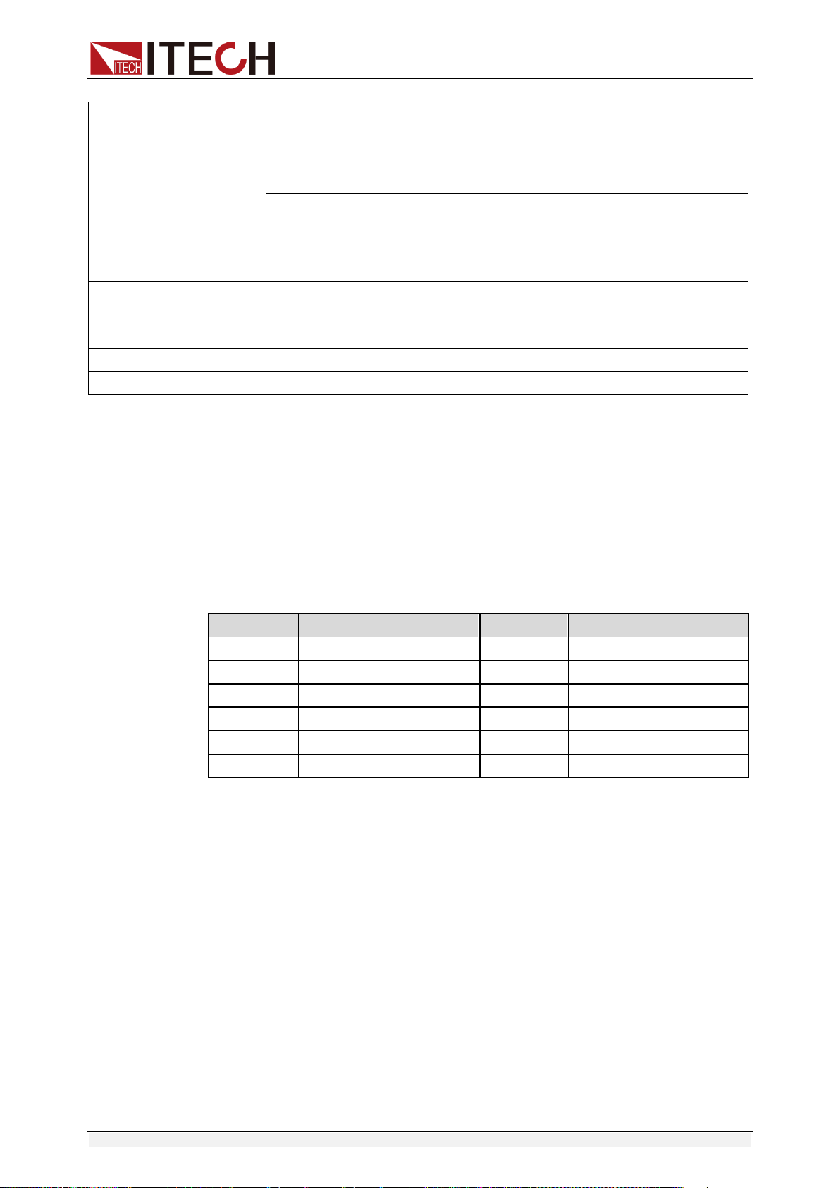
3. Check whether the fuse of power supply is burned out.
If yes, change fuse. Detailed steps:
1) Pull out power line and take out the fuse box at power line jack with a
small screw driver. As shown below.
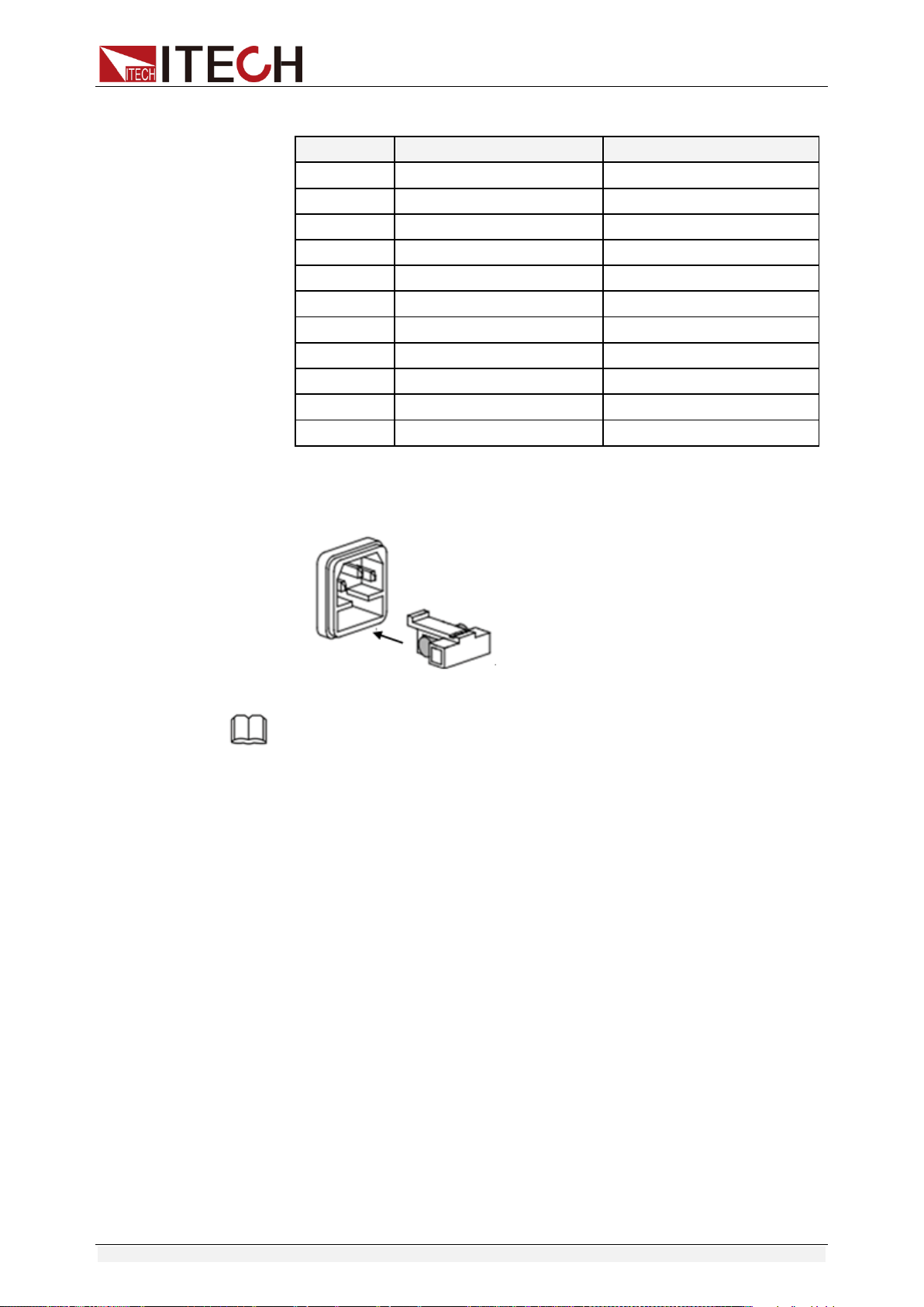
2) If the fuse is fused, please change fuse of same specification based on
machine model. See the table blow for matching information of fuse
OFF
0.000V 0.0000A
Quick Start
Copyright ©ITECH Electronic Co., Ltd. 12
and machine model.
Products
Specification (110VAC)
Specification (220VAC)
IT6922A
T4A 250V
T2A 250V
IT6932A
T6.3A 250V
T3.15A 250V
IT6933A
T6.3A 250V
T3.15A 250V
IT6942A
T10A 250V
T6.3A 250V
IT6952A
T15A 250V
T10A 250V
IT6953A
T15A 250V
T10A 250V
IT6922B
T4A 250V
T2A 250V
IT6932B
T6.3A 250V
T3.15A 250V
IT6942B
T12.5A 250V
T6.3A 250V
IT6952B
T15A 250V
T10A 250V
IT6953B
T15A 250V
T10A 250V
3) After replacement, install the fuse box back to original position, as
shown below.
NOTE
Fuse of IT6952A/IT6953A/IT6952B/IT6953B can unscrew directly by hand.
Function and Features
Copyright ©ITECH Electronic Co., Ltd. 13
Chapter3 Function and Features
3.1 Local/Remote Mode
Local button can enable you switch mode from remote to local mode.
After you power on the power supply, unit will default in local mode, all the
buttons can be used in this mode. While in remote mode, you can’t operate
through front panel directly. Local and remote mode can be controlled through
PC. In addition, the mode changing will not influence the output parameters.
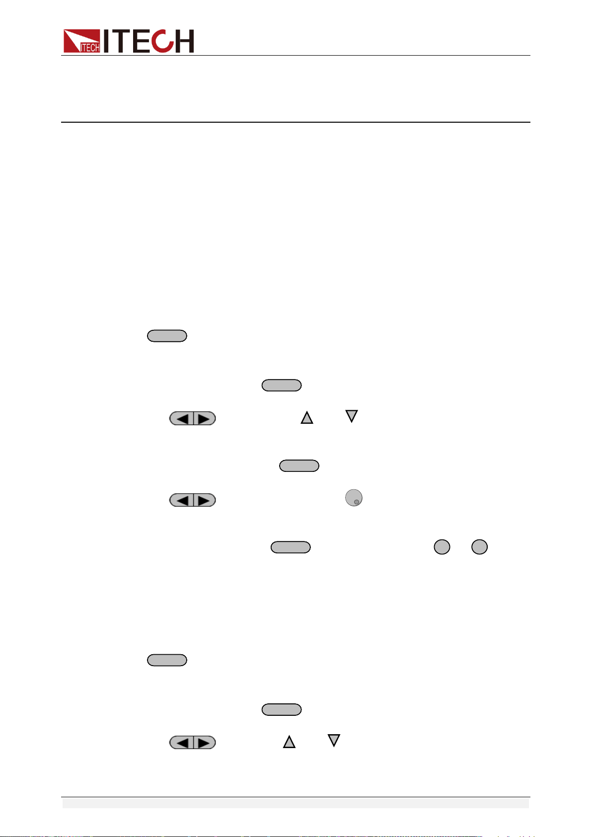
3.2 Voltage Setup
You can set voltage within the range of rated voltage value. When you press
V-setV-set
button, the button will be lit. This indicates that you can set voltage.
There are three ways to set output voltage through front panel.
The first way: press
V-setV-set
,adjust cursor location through
button, pressing and will enable you to adjust the
setting voltage value.
The second way: press
V-setV-set
, adjust cursor location through
button, adjust rotary knob to change the setting voltage
value.
The third way: press
V-setV-set
button and number key(
0
to
9
) to set
voltage value.
3.3 Current Setup
You can set current within the range of rated current value. When you press
I-setI-set
button, the button will be lit. This indicates that you can set current.
There are three ways to set output current through front panel.
The first way: press
I-setI-set
,adjust cursor location through
button, push and will enable you to adjust the setting
current value.

Function and Features
Copyright ©ITECH Electronic Co., Ltd. 14
The second way: press
I-setI-set
,adjust cursor location through
button, adjust rotary knob to change the setting current
value.
The third way: press
I-setI-set
button and number key(
0
to
9
) to set
current value.
3.4 On/Off Operation
On/Off
button is used to control the output state of power supply. When
On/Off
button is lit, this indicates the output is in on mode. When output is
open, the working state indicator light(CV/CC) will be lit.
Note: make sure you have connected power supply well, then press
On/Off
button.
3.5 Setup value/Actual value
You can switch the display between setting value and actual value by
pressing
MeterMeter
button. When this button is lit, screen displays actual output
value and the indicator light “meter” will be lit on the VFD board. In other words,
when the button is not lit, the front panel displays setting value.
3.6 Voltage/Current/Power adjustment
The output current value is determined by output voltage of power supply and
electronic load’s resistance. Only when the actual current value is lower than
the setting current value, can power supply work in CV mode and the will CV
indicator light be lit.
If output current is higher than the setting value, then power supply will function
in CC mode. And the CC indicator light will be lit.
The output voltage and current value are also influenced by the upper limit of
output power. Take IT6932A (60V/10A/200W) for example, suppose you set the
max power value to be 200W, then when the setting output voltage and current
is 25V/10A, in fact, the unit can only output 25V/8A.
3.7 Saving Operation
Customer can save some often-used parameters in nonvolatile memory. You
can use the button +
Recall
(Save) button or SCPI order *SAV, *RCL to
achieve this function. Saving parameters include: setting voltage/setting current
Function and Features
Copyright ©ITECH Electronic Co., Ltd. 15
Saving method:
Press +
Recall
(save) button, and then input the group number you want
to save through number key board. Press enter button to confirm. If you want to
recall the saved parameters, press
Recall
button and corresponding group
number (number1-9).At last press enter button to confirm.
3.8 Trigger Operation
You need to select the trigger mode from the menu before using this function.
After you edit a list file, press +
Enter
(Trigger) to give a trigger signal.
During the running process,
Enter
button will be lit all the time.
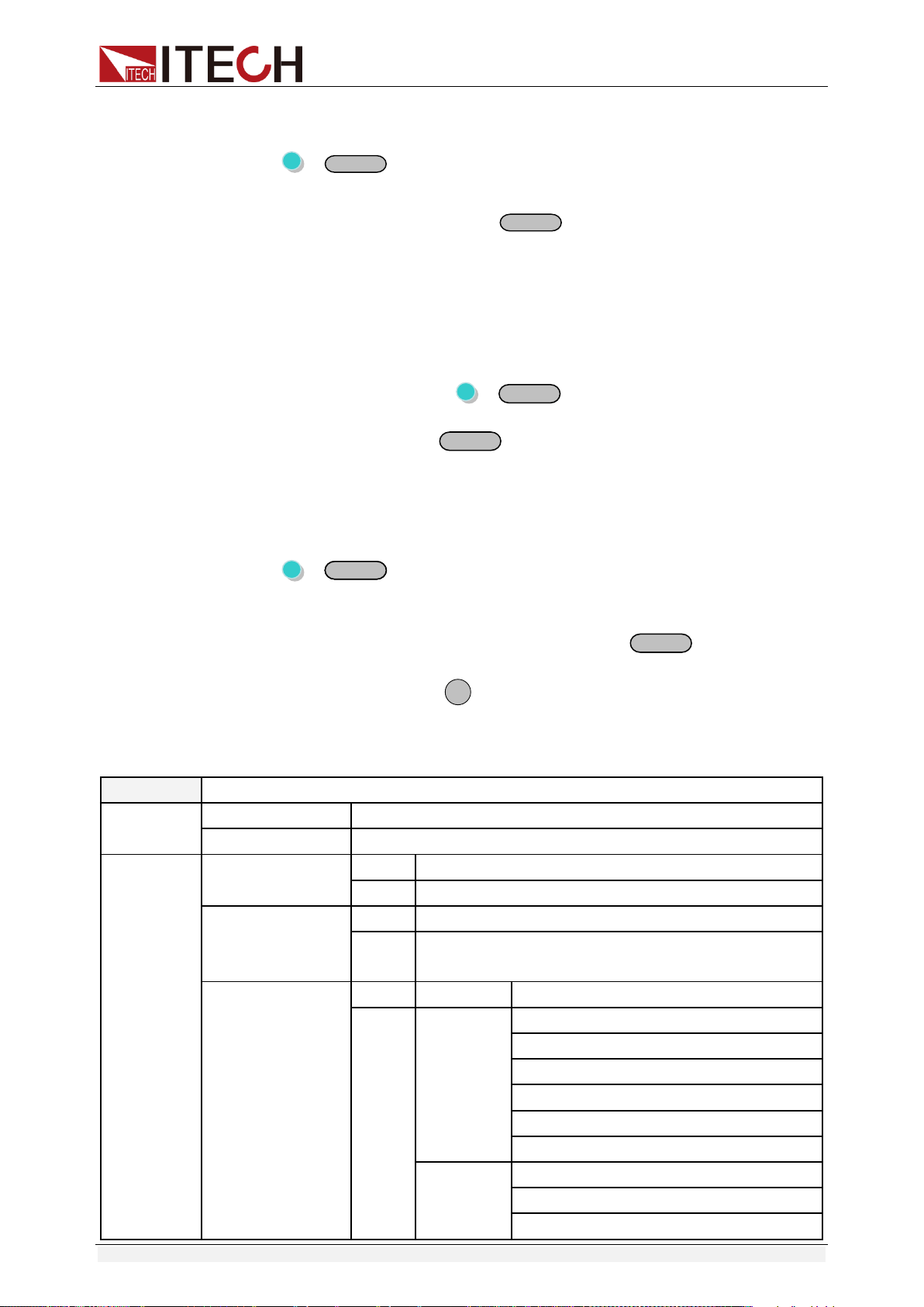
3.9 Menu Operation
Press +
I-setI-set
(Menu) to enter the menu. You will see a optional items on
the screen, through direction keys and rotary knob to upturn VFD display, then
the screen will display the following functions .Press
Enter
button will enter
corresponding items. Press
ESC
button will return to previous menu.
IT6922A/IT6932A/IT6933A/IT6942A/IT6952A/IT6953A power supply menu
function is shown as below.
MAX VOLT
Set the max output voltage
OCP SET
OFF
Disable the over current protection function.
ON
Enable the over current protection function.
SYST SET
P-MEN (RESET)
Reset
Power is restored to factory setting
Keep
Set the power-on state as the last power off state
P-OUT (OFF)
OFF
Enable the power-on output state to be off mode
Keep
Set the power-on output state to be the last power-off
output state
COMM (GPIB)
GPIB
ADDR
Address can be set within 0-30
RS232
BAUD
4800
9600
19200
38400
57600
115200
NONE 8BIT
NONE 8BIT
EVEN 8BIT
ODD 8BIT
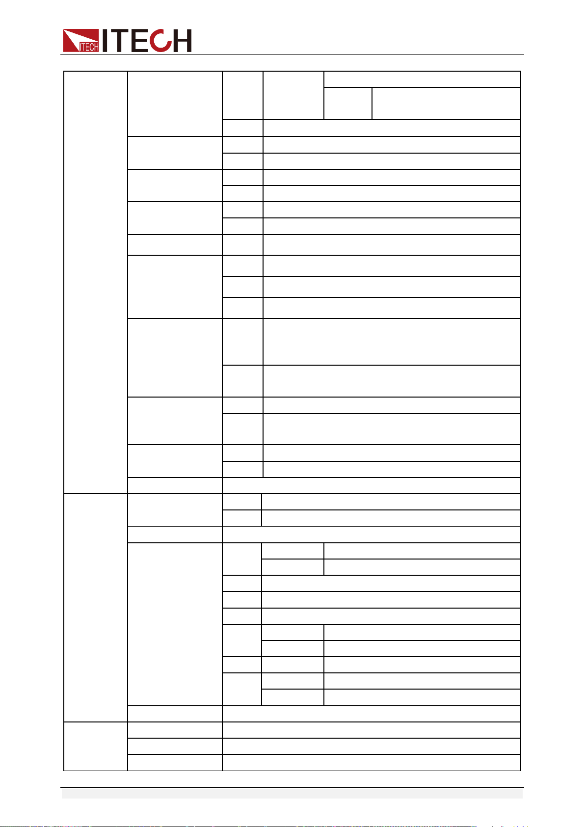
Function and Features
Copyright ©ITECH Electronic Co., Ltd. 16
MODE
SIGNAL
MUX
ADDR. Address can be set
within 0-30
USB
BEEP (ON)
OFF
Close the key sound
ON
Open the key sound
KNOB (ON)
LOCK
Lock the rotary knob function
ON
Unlock the rotary knob function
TRIG (MANUAL)
MANU
Local keyboard trigger
BUS
External trigger
MEM (GROUP1)
GRP1-8
Save and recall operation
ADC SPEED
SLOW
AD speed is low speed
MID
AD speed is middle speed
FAST
AD speed is high speed
METER RETURN
WAIT 5
S
In the voltage/current setting state (or the LOCK state to
view the set value), if there is no operation in 5S, it will
automatically return to the measurement state.
NO
It does not automatically return to the measurement
state.
TIMER SET
OFF
Close the timer function
ON
Open the timer operation, the time can be set within
0.1-99999.9s
RESET
NO
keep the original setting
YES
restore the factory setting
EXIT
Quit the menu setting
LIST SET
LIST STATE
OFF
Close list test function
ON
Open list test function
LIST LOAD
Recall the saved list file(FILE0-FILE9)
LIST EDIT
TIME
(SEC)
SEC
second
MIN
minute
VSET
Setup the single step voltage
ISET
Setup the single step current
SEC
Setup single step delay time(0.1-9999)
NEXT
(YES)
YES
continue the edit of next step
NO
End up the list file edit
REPET
1-65535
Set the cycle time of list file
SAVE
NO
Do not save the current list file
FILE0-FILE9
Save the list file to appointed document
EXIT
Quit the system menu
POWER
INFO
MODEL
Unit model
VER
The software version
SN-1
The first six number of SN
Function and Features
Copyright ©ITECH Electronic Co., Ltd. 17
SN-2
The middle six number of SN
SN-3
The last six number of SN
EXIT
Quit the information menu
EXIT MENU
Quit the main menu
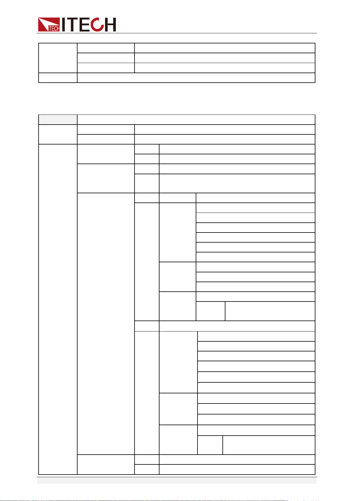
IT6922B/IT6932B/IT6942B/IT6952B/IT6953B power supply menu function is
shown as below.
MAX VOLT
Set the max output voltage
OCP SET
OFF
Disable the over current protection function.
ON
Enable the over current protection function.
SYST SET
P-MEN (RESET)
Reset
Power is restored to factory setting
Keep
Set the power-on state as the last power off state
P-OUT (OFF)
OFF
Enable the power-on output state to be off mode
Keep
Set the power-on output state to be the last power-off
output state
COMM (GPIB)
GPIB
ADDR
Address can be set within 0-30
RS232
BAUD
4800
9600
19200
38400
57600
115200
NONE 8BIT
NONE 8BIT
EVEN 8BIT
ODD 8BIT
MODE
SIGNAL
MUX
ADDR. Address can be set
within 0-30
USB
RS485
BAUD
4800
9600
19200
38400
57600
115200
NONE 8BIT
NONE 8BIT
EVEN 8BIT
ODD 8BIT
MODE
SIGNAL
MUX
ADDR. Address can be set
within 0-30
BEEP (ON)
OFF
Close the key sound
ON
Open the key sound
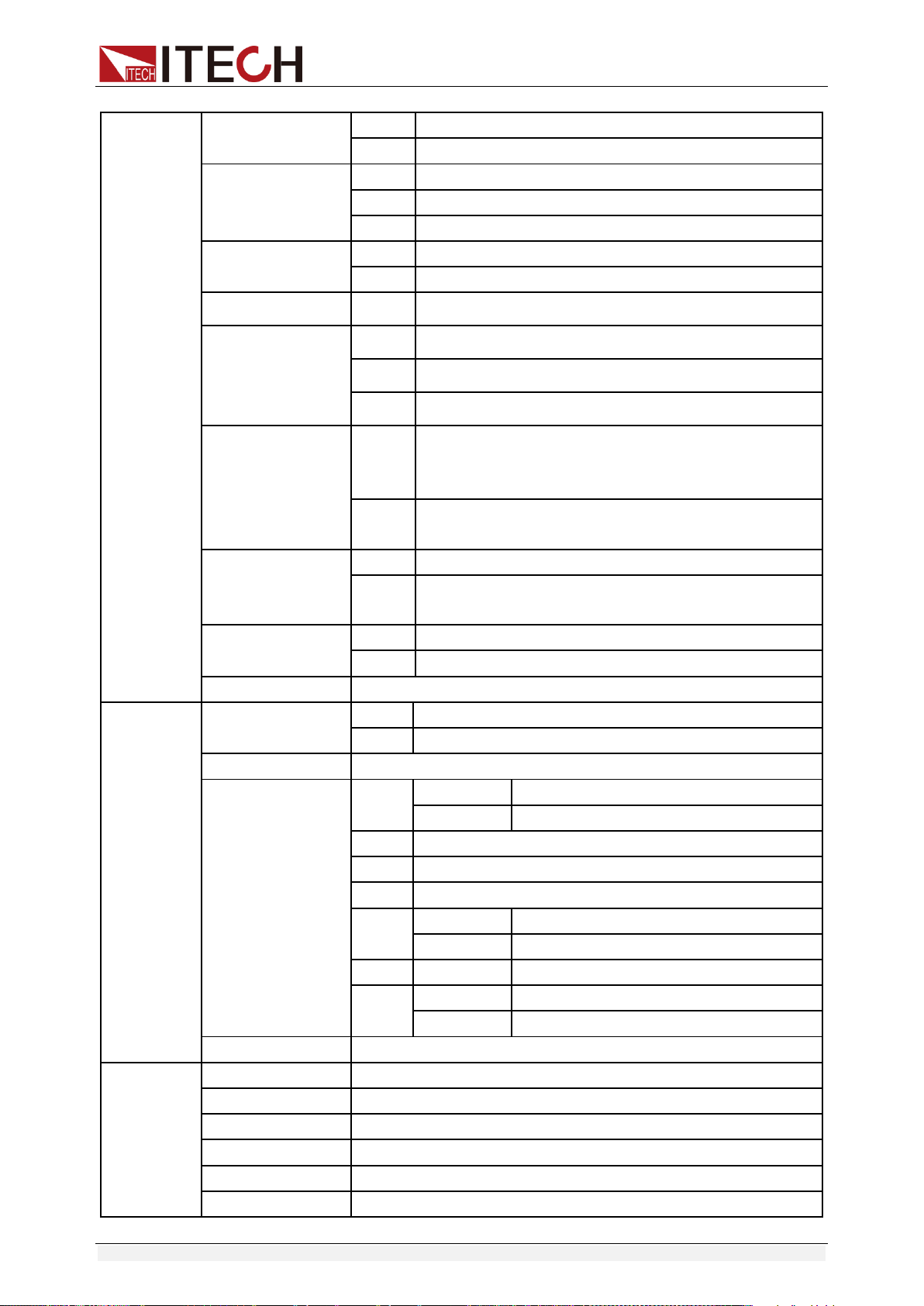
Function and Features
Copyright ©ITECH Electronic Co., Ltd. 18
KNOB (ON)
LOCK
Lock the rotary knob function
ON
Unlock the rotary knob function
Ext-C
OFF
Disable external signal control function
ANA
Enable external analog control function
DIGIT
Enable external digital control function
TRIG (MANUAL)
MANU
Local keyboard trigger
BUS
External trigger
MEM (GROUP1)
GRP1-8
Save and recall operation
ADC SPEED
SLOW
AD speed is low speed
MID
AD speed is middle speed
FAST
AD speed is high speed
METER RETURN
WAIT 5
S
In the voltage/current setting state (or the LOCK state to
view the set value), if there is no operation in 5S, it will
automatically return to the measurement state.
NO
It does not automatically return to the measurement
state.
TIMER SET
OFF
Close the timer function
ON
Open the timer operation, the time can be set within
0.1-99999.9s
RESET
NO
keep the original setting
YES
restore the factory setting
EXIT
Quit the menu setting
LIST SET
LIST STATE
OFF
Close list test function
ON
Open list test function
LIST LOAD
Recall the saved list file(FILE0-FILE9)
LIST EDIT
TIME
(SEC)
SEC
second
MIN
minute
VSET
Setup the single step voltage
ISET
Setup the single step current
SEC
Setup single step delay time(0.1-9999)
NEXT
(YES)
YES
continue the edit of next step
NO
End up the list file edit
REPET
1-65535
Set the cycle time of list file
SAVE
NO
Do not save the current list file
FILE0-FILE9
Save the list file to appointed document
EXIT
Quit the system menu
POWER
INFO
MODEL
Unit model
VER
The software version
SN-1
The first six number of SN
SN-2
The middle six number of SN
SN-3
The last six number of SN
EXIT
Quit the information menu

Function and Features
Copyright ©ITECH Electronic Co., Ltd. 19
EXIT MENU
Quit the main menu
NOTE
Pressing
ESC
button can enable you to quit any function setting.
Maximum voltage set (>MAX VOLT)
The range of setting voltage is from 0V to rated voltage. You can press +
I-setI-set
(Menu) button to enter the menu, then press direction key to
select >MAX VOLT item. Press
Enter
button to confirm. After you set the
max voltage value, the output voltage value can only be set less than the max
voltage. Our default max voltage value is the rated value.
Power-on parameters set (>P-MEN)
This item can set power on state of parameters. If you select RESET item, then
all the parameters will be initialized to the factory setting. Output voltage and
current will always be 0V/0A. Or the output value will be the same with last
power off state. The default setting is RESET item.
Power On Output State (>P-OUT)
This item can set the power on output state. If you select keep item, that
indicates the power on output state is the same with last power off output state.
If you select off item, unit will automatically in off mode when you power on.
Default setting is OFF item.
Communication (>COMM)
Our unit has provided three standard communication interfaces:
RS232/USB/GPIB. In this option, you can select the communication interface
according to your demands. The range of GPIB address is 0-30. Besides, we
have multi-baud rate to be chosen in RS232
mode---4800,9600,19200,38400,57600,11.52K.Data bit is 8,Check digit have
three choices: NONE, ODD, EVEN. Before you begin to carry out
communication, please make sure the configure in our unit agrees with PC
configure.
Key Sound Set (>BEEP ON)
This item can set the key sound state. If in on mode, then key sound will be
there when you press buttons. If in off mode, the beeper will not make a sound.
The default set is in on mode.

Function and Features
Copyright ©ITECH Electronic Co., Ltd. 20
Rotary Knob Set (>KNOB)
This item is used to set rotary knob state. In on mode, you can use this rotary
knob to set the output value and overturn the menu items. In lock mode, this
knob can’t be used. The default setting is in on mode.
External Signal Control Function (>Ext-C)
(IT6922B/IT6932B/IT6942B/IT6952B/IT6953B Specific function)
This item is used to enable or disable signal control. When OFF is selected,
function is disabled; when ANA (analog control) is selected, external analog
control function is enabled; when DIGIT (digit control) is selected, external digit
control function is enabled. The default set is in OFF option. This function will
be described in details below.
Trigger mode (>TRIG)
Before you running a list file, you need a trigger signal. Thus you must set the
trigger mode firstly, in keyboard trigger mode or in external trigger mode. In
MANU trigger mode, press +
Enter
button can generate a trigger
signal. In BUS trigger mode, you can only through sending orders to trigger.
The default set is MANU option.
Group Set (MEM GROUP)
Power supply can save some often-used parameters in a nonvolatile memory
(capacity is 9*8 groups). This function can make the operations more
convenient. Customer can save and recall parameters quickly.
GRP1: This indicates saving power supply parameters in 1-9 groups. Press
+
Recall
(Save) and the group number (1-9) can save the parameters in
corresponding groups.
GRP2: This indicates saving the parameters in 10-18 groups. Press +
Recall
(Save)+saved group number(1-9) can save related parameters. Note
that the current number “1” represents parameters are saved in 10
th
groups.
Number “2” represents the parameters are saved in 11
th
groups.
GRP3-GRP8 by parity of reasoning.
AD Speed Set (>ADC SPEED)
This item is used to set the AD speed, i.e., measurement display speed of
power supply. There are three kinds of AD speed, including SLOW, MID and
FAST. Ex-factory set is in SLOW option.

Function and Features
Copyright ©ITECH Electronic Co., Ltd. 21
NOTE
When AD speed of power supply is set to MID or FAST, the measurement accuracy is too
low to reach the middle accuracy in the specification. Only when AD speed of power
supply is set to SLOW can the middle accuracy in the specification be reached.
Timer Set (>TIMER SET)
This item is used to set the “time on- load” function. In ON mode, the indicator
light “Timer” will be lit on the VFD screen. When output of power supply is
opened, timer will begin to work, after reaching the definite time, output will be
off automatically. If in OFF mode, the timer function will not be enabled. The
default set is in OFF option.
Reset (>RESET)
This item is used to reset all items in the menu. If you select >YES, then unit will
be restored to factory setting. If you select >NO, all setting in the menu will
remain unchanged.
List Mode (>List Set)
Before you edit a list file, please set the trigger mode: manual mode.
Press +
I-setI-set
button to enter the menu, then press direction key to
select >SYST SET option, after that please push
Enter
button to confirm. At
last please press direction key to select >Trig MANUAL and push
Enter
button to confirm.
You can make the output change order by editing every step value of list
operation. The parameters you need to edit includes: single-step voltage,
single-step current, single-step delay time and whether to go on the next step.
Besides, you also need to set the repeat times and save list sequence file. After
you finish the editing process, at this time if you receive a trigger signal, power
supply will begin to work according to the sequence steps you’ve edited. Now
we take five steps for an example:
Operation steps:
1. Press +
I-setI-set
(Menu) button to enter the menu
2. VFD display >MAX VOLT, press to select >LIST SET, press
Enter
to
confirm
3. VFD display >LIST STATE, press to select >LIST EDIT, press
Enter
to confirm
4. VFD display >TIME SEC, press
Enter
to confirm, go to the next step,
Function and Features
Copyright ©ITECH Electronic Co., Ltd. 22
you can also through button to select >TIME MIN time unit, press
Enter
to confirm.
5. VFD display >VSET 0.000, press number key
0
to
9
or through
rotary knob to set voltage, after that press
Enter
to confirm.
6. VFD display ISET 0.0000, press number key
0
to
9
or rotary knob to
set the single-step current, press
Enter
to confirm.
7. VFD display SET 0.1, press number key
0
to
9
or rotary knob to set
single-step delay time, press
Enter
to confirm.
8. VFD display NEXT >YES, press
Enter
to confirm.
9. Repeat the steps from 5) to 8) and set the four steps’ voltage/current and
delay time separately. When screen display NEXT>YES in the fourth step
edit process, please press to select NEXT >NO, press
Enter
to
confirm.
10. VFD display REPET 1, press number key
0
to
9
or rotary knob to set
the repeat times, press
Enter
to confirm.
11. VFD display SAVE >NO, press
Enter
to confirm, in this circumstance,
the list file is not saved but can run for one time, or you can press
button to select >SAVE FILE0,saving the list test file in FILE0~FILE9, press
Enter
to confirm. You can recall the file in the following utilization.
12. If you do not save the list test file, VFD will display LIST EDIT; if you select
to save the test file, VFD will display SAVE DONE for three seconds, and
then display LIST EDITL.
13. Press to select >LIST STATE item, press
Enter
to confirm.
14. VFD display LIST >OFF, press to select >LIST >ON, press
Enter
to
confirm. Now
Enter
button will be lit. This indicates that list operation
function has been opened.

Function and Features
Copyright ©ITECH Electronic Co., Ltd. 23
15. VFD display >LIST STATE, pressing
Esc
button can quit the operation.
16. Press
On/Off
button to open the output, press +
Enter
(Trigger) to
give a trigger signal.
17. If you have edited several list files, you can select LIST LOAD item to recall
the file you need. And then press
Esc
to quit this operation. Press
On/Off
button to open the output. Now you only need to press
+
Enter
(Trigger) to give a trigger signal, the list file can be ran.
18. In LIST mode, voltage set and current set button can’t be used, In LIST
STATE item, choose LIST>OFF will enable you to quit list mode.
3.10 OVP Function
IT6900 series power supply provide OVP function, press +
V-setV-set
button
can enable you to set the over voltage protection value. Over voltage may
caused by internal defect or customer’s incorrect operation(such as output
voltage rising),or external voltage too high. Once power supply is
protected(OVP), the output will be off immediately and “OVP” indicator light will
be lit, the VFD display “OVER VOLT”.
Avoid external voltage that across the output terminals exceeding the 120% of
rated voltage or it will damage out power supply!
When power supply in OVP state, please check the external factors first, after
you exclude the external factors, press ON/OFF button to open output again. If
in communication state originally, you should by sending order OUTP ON order
to open output.
3.11 Key Lock
Press +
On/Off
(Lock) button to set the key lock state. If keyboard has
been locked, the indicator light LOCK will display on the VFD screen. In
addition, when key board are lock, all buttons can’t be used but ON/OFF, Meter
button, shift button. Press this button once again will relieve key lock function.

Function and Features
Copyright ©ITECH Electronic Co., Ltd. 24
3.12 Rear Pins Function
3.12.1 Remote sense and DVM terminals
+, - : output terminals, the same with front panel output terminals.
S+, S-: remote sense pins.
V+, V-: the output interface of a four semi-digital voltmeter.
Digital Volt Meter (DVM)
IT6900 series power supply has four semi-digital voltmeter. This DVM can
measure 0.001V to 61.000V voltage. Press +
MeterMeter
(DVM) button can
enable the measured value display on the VFD screen. Press any key to quit
the display of this value.
Remote sense function
Remote sense can adjusted at the output voltage of the device under test, this
feature allows to compensate the voltage drop on the wire between the front
panel terminals of the power supply and the device under test.
Use local sense:
Local sense doesn’t compensate the voltage drop on the connection wire, the
operation is:
1. Use the short clips on the back panel of the instrument, or install wire
between + and S+, - and S-.
2. Connect the positive and negative terminals of the front panel to the device
under test.
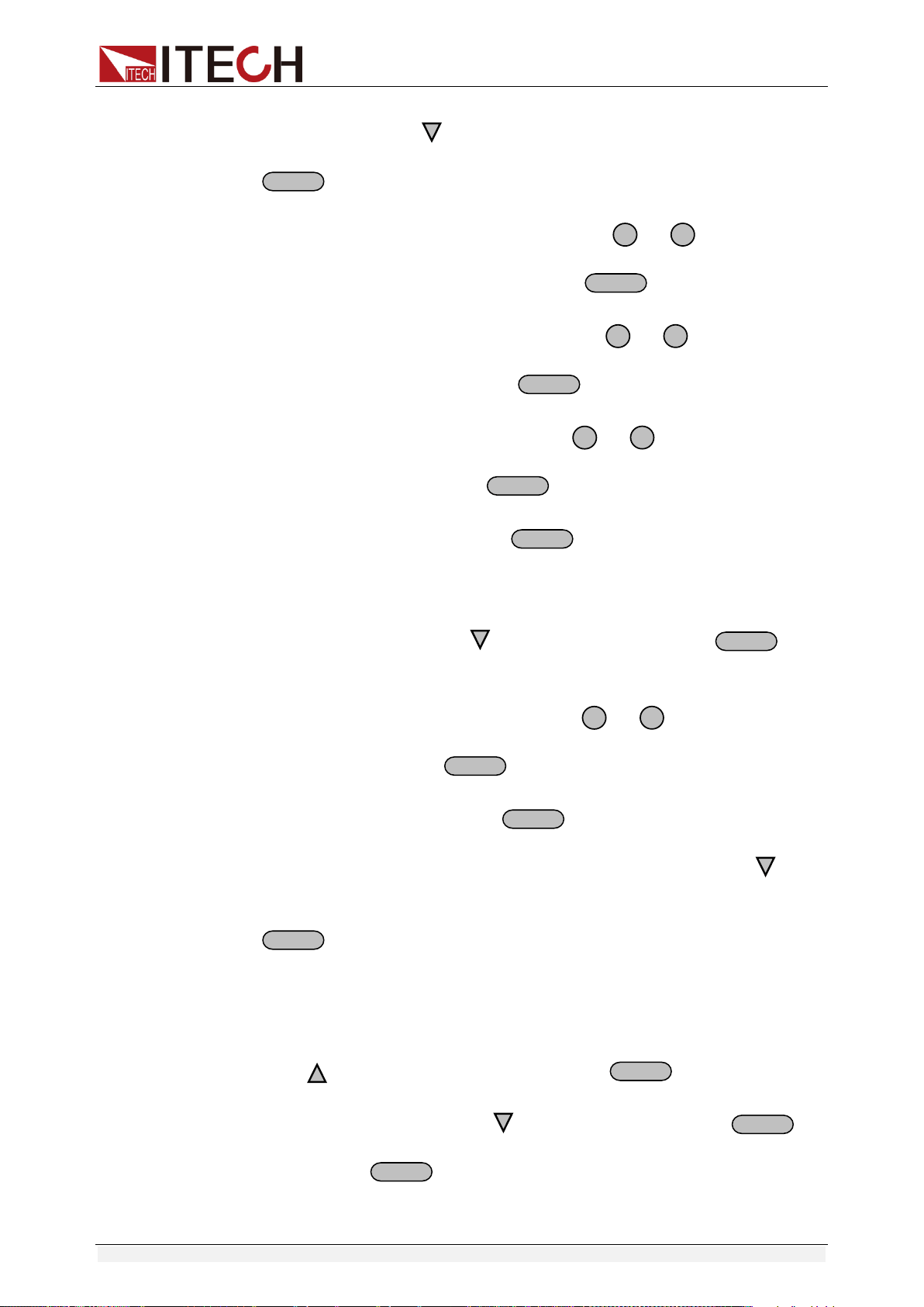
Use remote sense:
Remote sense compensate the voltage drop on the connection wire, the
operation is:
1. Disconnect the wires/short clips between + and S+, - and S-.
2. Connect wires from S+, S- to the device under test.
3. Connect wires from +, - to the device under test.
Function and Features
Copyright ©ITECH Electronic Co., Ltd. 25
NOTE
In order to ensure the stability of the system, using armored twisted pair cable between
the remote sense terminal of IT6900 and load.
Please note that the positive and negative polarity when wiring, otherwise it will damage
the instrument!
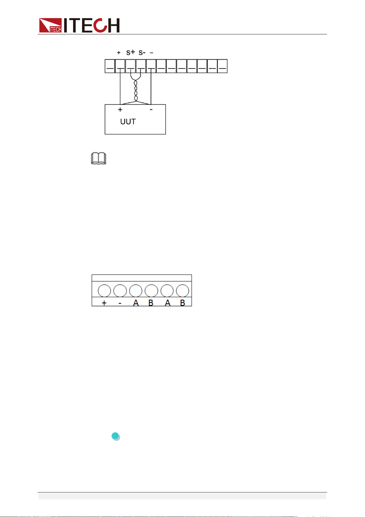
3.12.2 RS485 and Output Sync signal interface
Terminals on IT6922B/IT6932B/IT6942B/IT6952B/IT6953B power supply rear
board comprise Output Sync signal interface and RS485 communication
interface, as shown below.
+,-: Output Sync signal terminal
A, B: RS485 communication interface
DC source output indication function:
There is a Output Sync terminal which is used to indicate the output state of DC
source at the rear panel. When in output on mode, Output Sync terminal will
output a high level. When in off mode, Output Sync terminal will output a low
level.
RS485 communication interface
RS485 communication interface is often used for multiple devices control.
Press shift + I-set button to entry into the menu, user need to set the
parameters of Baud rate, Data bit, Stop bit, parity bit and address, the setting is
the same with RS232 communication setting.
Function and Features
Copyright ©ITECH Electronic Co., Ltd. 26
3.13 Analog Control Interface
IT6922B/IT6932B/IT6942B/IT6952B/IT6953B power supply output can be
controlled and monitored by external DC voltage source (0~10V).
If external analog control is not used, it must be disabled before normal front
panel operation can resume. Follow the steps below to enable or disable
external analog control.(Entry into the system menu----Enter button to
confirm-----select Ext-C item---choose ANA item and enable this mode. If
choose DIGIT, it means enable the external digital control function.)
Pin #
Label
Description
1
REF_10V
10V DC reference output
2
Vs/D0
Composite terminal: Voltage programming input/
Digital D0 input terminal
3
Is/D1
Composite terminal: Current programming input/
Digital D1 input terminal
4
D2
Digital D2 input terminal
5
ON/OFF
Control output state
6
Vm
Voltage monitoring output
7
Im
Current monitoring output
8
NULL
None
9
GND
Ground pin

Remote Operation Mode
Copyright ©ITECH Electronic Co., Ltd. 27
Chapter4 Remote Operation Mode
IT6900A series power supply has three standard communication
interface: RS232, USB, GPIB, and IT6900B series power supply has four
standard communication interface: RS232, USB, GPIB, RS485. The user
can choose any one of them to implement a communication with the
computer.
4.1 RS232 interface
There is a DB9 connector at the rear of the power supply, when connect to
computer, you need to connect a cable with COM port on both side. To active
connection, you need to set the front panel composite key +
I-setI-set
key configuration settings the same as computer configuration settings.
RS-232 interface can be used to program all of the SCPI orders.
NOTE
The RS232 settings must match the settings in front panel system information. If any
change, please press +
I-setI-set
key.
RS-232 data format
RS-232 data is a 10-bit words which has a start bit and a stop bit. The start bit
and stop bit cannot be edited. However, you can select the parity items with
+
I-setI-set
key on the front panel. Parity options are stored in nonvolatile
memory.
Baud Rate
The front panel +
I-setI-set
button allows the user to select a baud rate
which is stored in the non-volatile memory: 4800 /9600/ 19200 /38400/
57600 /115200.
RS-232 connection cable
Use a RS232 cable with DB-9 interface, RS-232 serial port can connect
with the controller (e.g. PC). Do not use blank Modem cable.
If your computer is using a RS-232 interface with DB-25 connector, you
need an adapter cable with a DB-25 connector at one end and the other
side is a DB-9(not blank modem cable)

Remote Operation Mode
Copyright ©ITECH Electronic Co., Ltd. 28
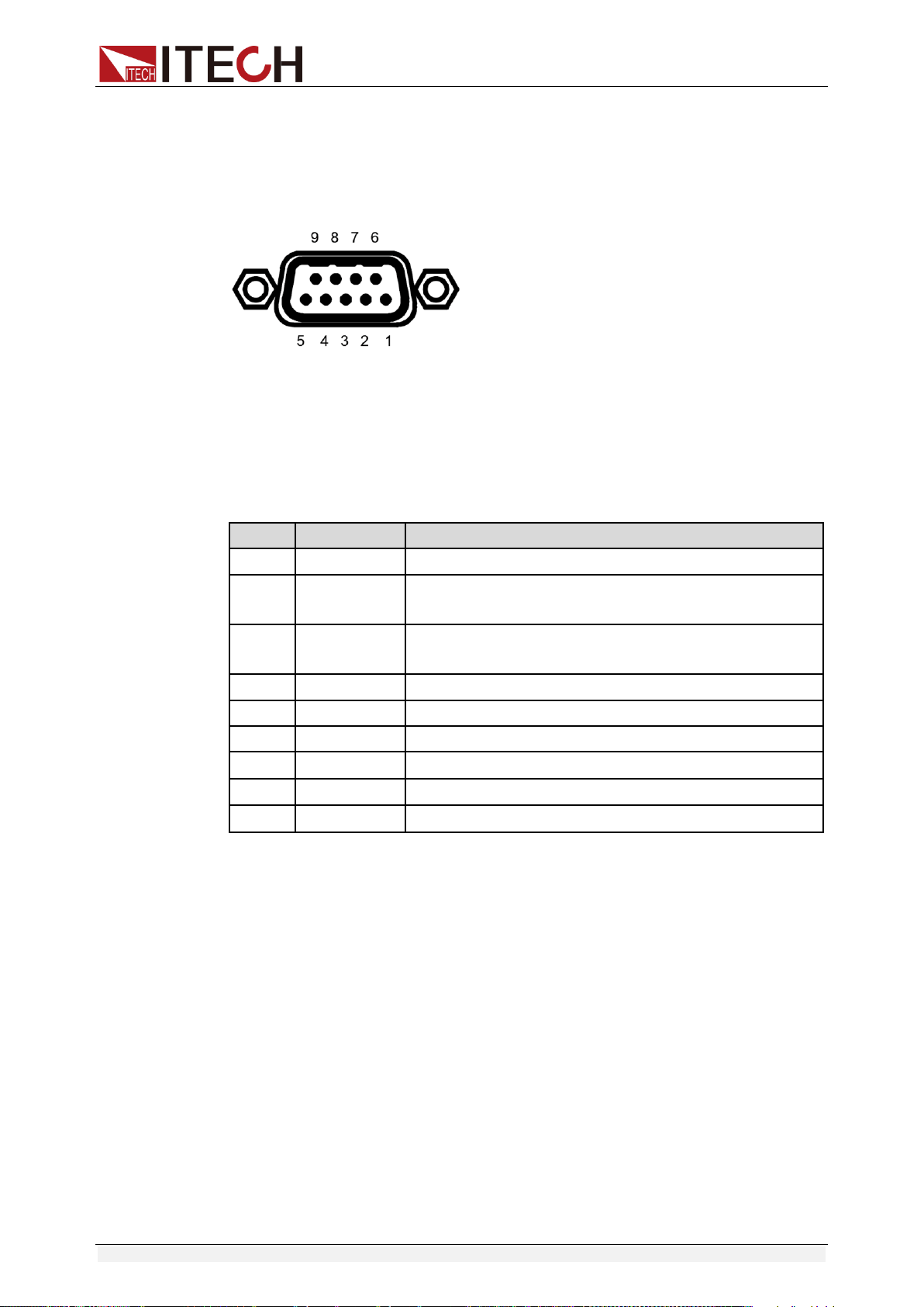
RS232 Pins of Plug
Base pin
number
Description
1
No conjunction
2
TXD, data transmission
3
RXD, data receiving
4
No conjunction
5
GND, grounding
6
No conjunction
7
CTS, clear to send
8
RTS, request to send
9
No conjunction
RS-232 Troubleshooting:
If there is RS-232 connection problem, check the following:
Computer and power supply must configure the same baud rate,
parity, data bits and flow control options. Note that the power
configuration as a start bit and a stop bit (these values are fixed).
As described before in RS-232 connector, you must use the correct
interface cable or adapter. Note that even if the cable has the right
plug, the internal wiring may be wrong.
Interface cable must be connected to the correct serial port on the
computer (COM1, COM2, etc.).
Communication Settings
Before communication, you should first make the following parameters of
power supply and PC matches.
Baud Rate: 9600 (4800,9600,19200,38400,57600,115200). You can
enter the system menu from the front panel, and then set the baud rate.
Calibration (none, even, odd)
EVEN 8 data bits, have even parity
ODD 8 data bits have odd parity
NONE 8 data bits, no parity
Mode: SIGNAL, MUX
SIGNAL (Single connection mode)
MUX (Multiple connection mode) ADDR: Local address (0 to 30, the
factory default setting is 0)
Start Bit
8 Data Bits
Parity=None
Stop Bit

Remote Operation Mode
Copyright ©ITECH Electronic Co., Ltd. 29
4.2 USB interface
Use a Cable with two USB port to connect the power and the computer.
All power functions can be programmed via USB.
The USB488 interface functions of the power supply described as below:
Interface is 488.2 USB488 interface.
Interface Receiver REN_CONTROL, GO_TO_LOCAL, and
LOCAL_LOCKOUT request.
Interface receive MsgID = TRIGGER USBTMC order information,
and will pass TRIGGER order to the functional layer.
Power USB488 device functions described as follows:
Devices can read all of the mandatory SCPI orders.
Device is SR1 enabled.
Device is RL1 enabled.
Device is DT1 enabled.
4.3 GPIB interface
First, Connect the GPIB interface on the power supply and the GPIB
card on computer via IEEE488 bus, must be full access and tighten the
screws. Then set the address, the address range of the power : 0 to 30,
can set by the function key on the front panel, press the +
I-setI-set
key
to enter the system menu function, find the GPIB address setting by
▼▼
button, type the address,
EnterEnter
key to confirm. GPIB address is
stored in nonvolatile memory line.
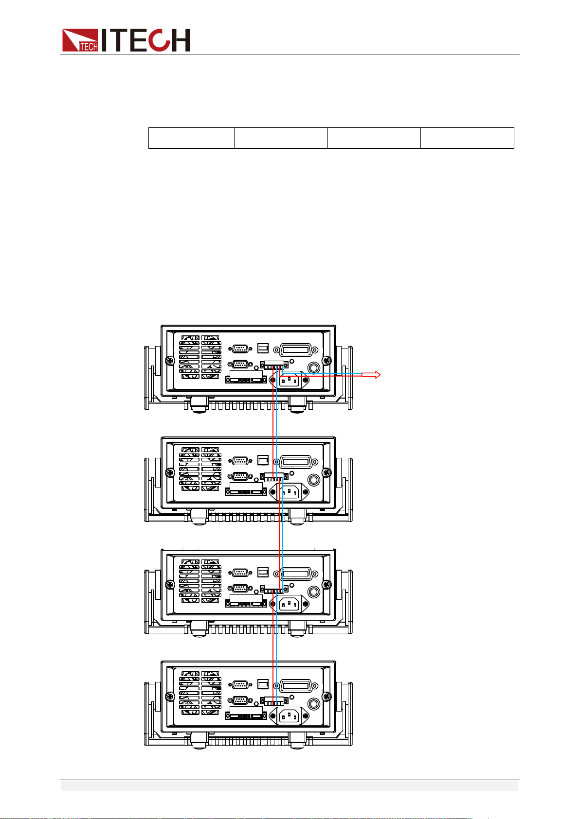
4.4 RS485 interface
IT6922B/IT6932B/IT6942B/IT6952B/IT6953B power supply, via the RS485
interface, provides multi-unit control function for up to 30 units (If connecting
more than 10 units, add a 120Ω resistor terminator to the last unit). On the front
panel, press (Shift)+
I-setI-set
keys to enter into the system menu, and the
related setting is the same as the RS232 communication setting.
User can set the following parameters of the RS485 interface:
Baud rate: 9600(4800/9600/19200/38400/57600/115200)
Parity and data bit: NONE/8BIT, EVEN/8BIT, ODD/8BIT
EVEN 8 data bits, have even parity
ODD 8 data bits have odd parity
NONE 8 data bits, no parity
Remote Operation Mode
Copyright ©ITECH Electronic Co., Ltd. 30
Mode: SIGNAL (Single connection mode)
MUX (Multiple connection mode) ADDR: Local address (0 to 30, the
factory default setting is 0)
Start Bit
8 Data Bits
Parity=None
Stop Bit
To set the multi-unit connection mode, access the system Menu→SYST
SET→COMM→RS485→MODE→MUX, to turn on the chain mode.
Set each unit with a different Address (0 to 30). Then by using RS485, connect
the first power supply in the chain to a PC. Now, multiple units daisy-chained
via RS485 can be controlled by one PC by using the commands specific for
multi-unit connection. See “Programming Guide” section for details.
The figure below is a schematic diagram of the connection of 4 machines.
Connect PC
Technical Specification
Copyright ©ITECH Electronic Co., Ltd. 31
Chapter5 Technical Specification
This chapter will introduce the main technical parameters of IT6900,such as
rated voltage/current/power and so on. Besides, we will introduce the working
environment and storage temperature.
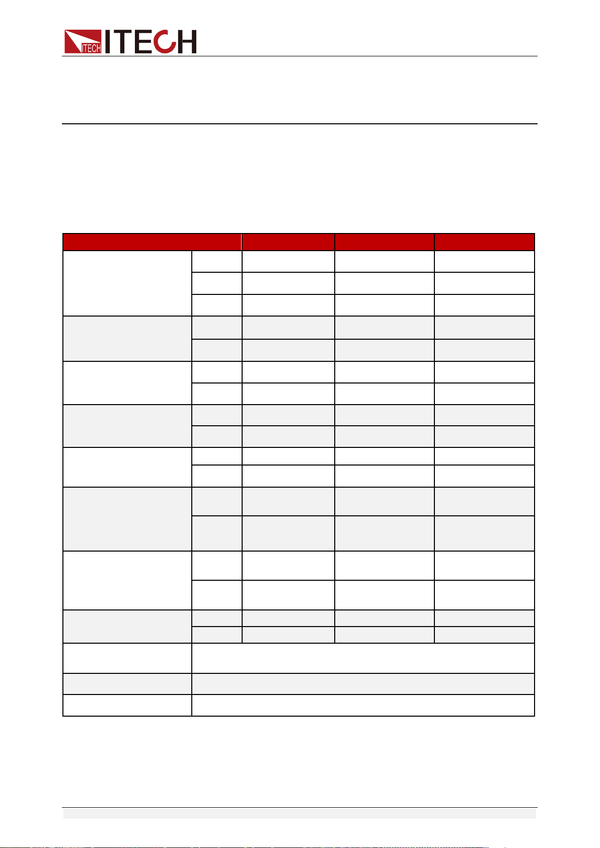
5.1 Major Technical Parameters
Parameters
IT6922A
IT6932A
IT6942A
Rated values
(0 °C~40 °C)
voltage
0~60V
0~60V
0~60V
current
0~5A
0~10A
0~15A
Power
100W
200W
360W
Load regulation
(%of output+offset)
voltage
≤0.01%+3mV
≤0.01%+10mV
≤0.01%+30mV
current
≤0.05%+2mA
≤0.05%+4mA
≤0.05%+6mA
Line regulation
±( %of output+offset)
voltage
≤0.01%+3mV
≤0.01%+10mV
≤0.01%+30mV
current
≤0.05%+2mA
≤0.05%+4mA
≤0.05%+6mA
Setup resolution
voltage
1mV
1mV
1mV
current
0.1mA
1mA
1mA
Readback resolution
voltage
1mV
1mV
1mV
current
0.1mA
1mA
1mA
Setup accuracy
(within twelve months)
(25°C±5°C)
(%of output+offset)
voltage
≤0.03%+5mV
≤0.03%+5mV
≤0.03%+5mV
current
≤0.1%+5mA
≤0.1%+10mA
≤0.1%+15mA
Read back resolution
(W) (25°C±5°C)
(%of output+offset)
voltage
≤0.03%+5mV
≤0.03%+5mV
≤0.03%+5mV
current
≤0.1%+5mA
≤0.1%+10mA
≤0.1%+15mA
Ripple
(20Hz ~20MHz)
voltage
≤5mVp-p
≤8mVp-p
≤15mVp-p
current
≤5mArms
≤6mArms
≤8mArms
Sample rate
10HZ
Dimension (mm)
214.5mmW×88.2mmH×354.6mmD
Weight (net)
7.7Kg
Technical Specification
Copyright ©ITECH Electronic Co., Ltd. 32
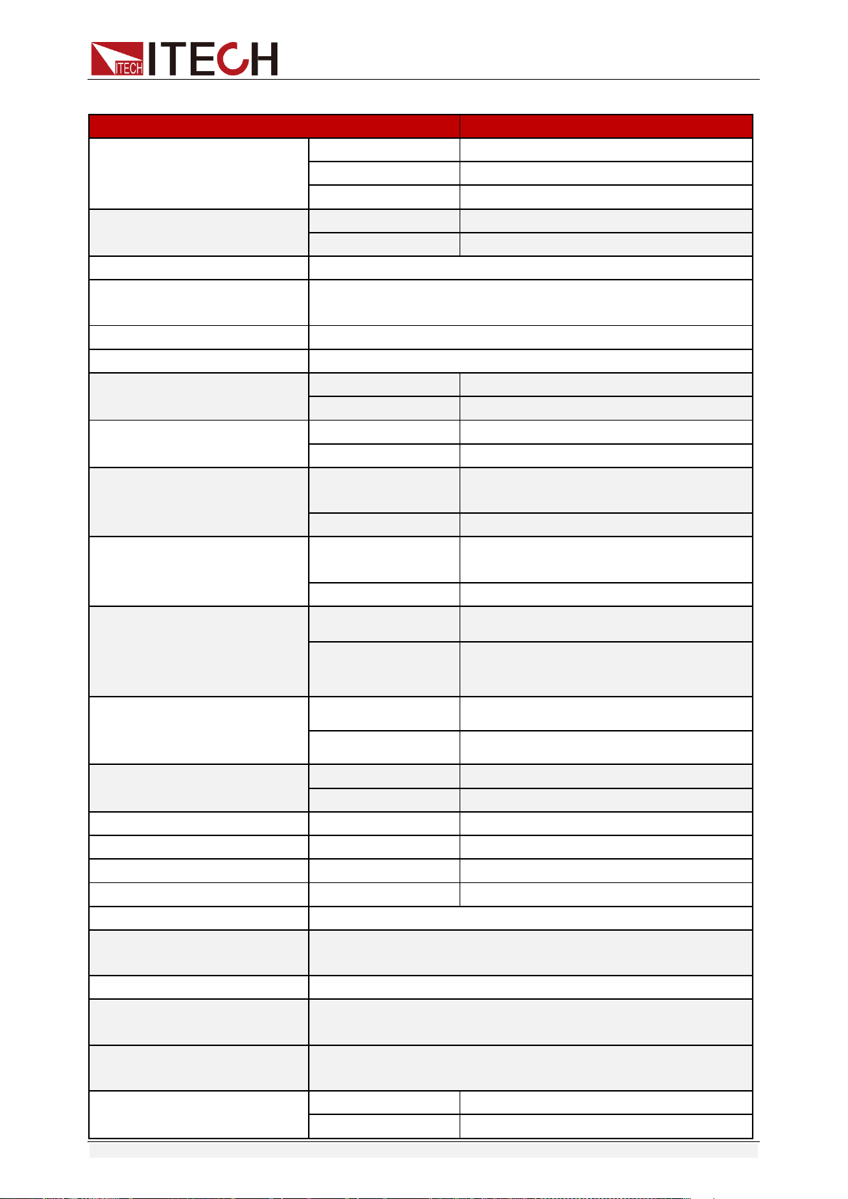
Parameters
IT6933A
Rated values
(0 °C~40 °C)
voltage
0-150V
current
0-5A
Power
200W
AC Input
voltage
220VAC ±10%/110VAC ±10%
Frequency
47 Hz ~63Hz
Maximum input current
2A
Maximum input apparent
power
500VA
Efficiency
0.55
Power Factor
0.7
Load regulation
(%of output+offset)
voltage
≤0.01%+20mV
current
≤0.01%+6mA
Line regulation
(%of output+offset)
voltage
≤0.01%+20mV
current
≤0.01%+6mA
Setup resolution
voltage
1mV(<100V),
10mV(≥100V)
current
0.1mA
Readback resolution
voltage
1mV(<100V),
10mV(≥100V)
current
0.1mA
Setup accuracy
(within twelve months)
(25°C±5°C)
(%of output+offset)
voltage
≤0.04%+30mV
current
≤0.1%+10mA
Read back resolution
(W) (25°C±5°C)
(%of output+offset)
voltage
≤0.04%+30mV
current
≤0.1%+10mA
Ripple(20Hz ~20MHz)
voltage
≤30mVp-p
current
≤6mArms
Rise time(No-load)
voltage
200ms
Rise time(Full-load)
voltage
300ms
Fall time(No-load)
voltage
2s
Fall time(Full-load)
voltage
150ms
Transient Response Time
200us
Remote Sense
Compensation
1V
Command Response Time
10~600ms
Difference-mode
voltage(Vpp)
50mV
Difference-mode current
(Arms)
20mA
Setup Temp.coefficient
( 0 °C~40 °C)
voltage
50 PPM/°C +30mV
current
50 PPM/°C +30mA
Technical Specification
Copyright ©ITECH Electronic Co., Ltd. 33
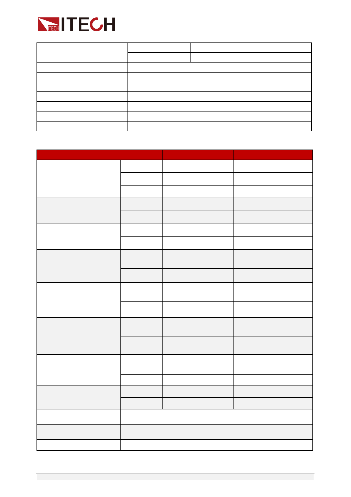
Parameters
IT6952A
IT6953A
Rated values
(0 °C~40 °C)
voltage
0~60V
0~150V
current
0~25A
0~10A
Power
600W
600W
Load regulation
(%of output+offset)
voltage
≤0.01%+30mV
≤0.01%+25mV
current
≤0.1%+10mA
≤0.05%+10mA
Line regulation
±( %of output+offset)
voltage
≤0.01%+30mV
≤0.01%+25mV
current
≤0.1%+10mA
≤0.05%+10mA
Setup resolution
voltage
1mV
1mV(<100V)
10mV(>100V)
current
1mA
1mA
Readback resolution
voltage
1mV
1mV(<100V)
10mV(>100V)
current
1mA
1mA
Setup accuracy
(within twelve months)
(25°C±5°C)
(%of output+offset)
voltage
≤0.03%+5mV
≤0.03%+20mV
current
≤0.1%+25mA
≤0.1%+25mA
Read back resolution
(W) (25°C±5°C)
(%of output+offset)
voltage
≤0.03%+5mV
≤0.03%+20mV
current
≤0.1%+25mA
≤0.1%+25mA
Ripple
(20Hz ~20MHz)
voltage
≤20mVp-p
≤50mVp-p
current
≤15mArms
≤15mArms
Sample rate
10HZ
Dimension (mm)
214.5mmW×88.2mmH×445mmD
Weight (net)
15Kg
Readback Temp.coefficient
( 0 °C~40 °C)
voltage
50 PPM/°C +30mV
current
50 PPM/°C +30mA
Working temperature
0-40°C
Storage temperature
-10-70°C
Series number
2
Parallel number
2
Isolation(output to ground)
240V
Dimension (mm)
214.5mmW×88.2mmH×354.6mmD
Weight (net)
7.7Kg
Technical Specification
Copyright ©ITECH Electronic Co., Ltd. 34
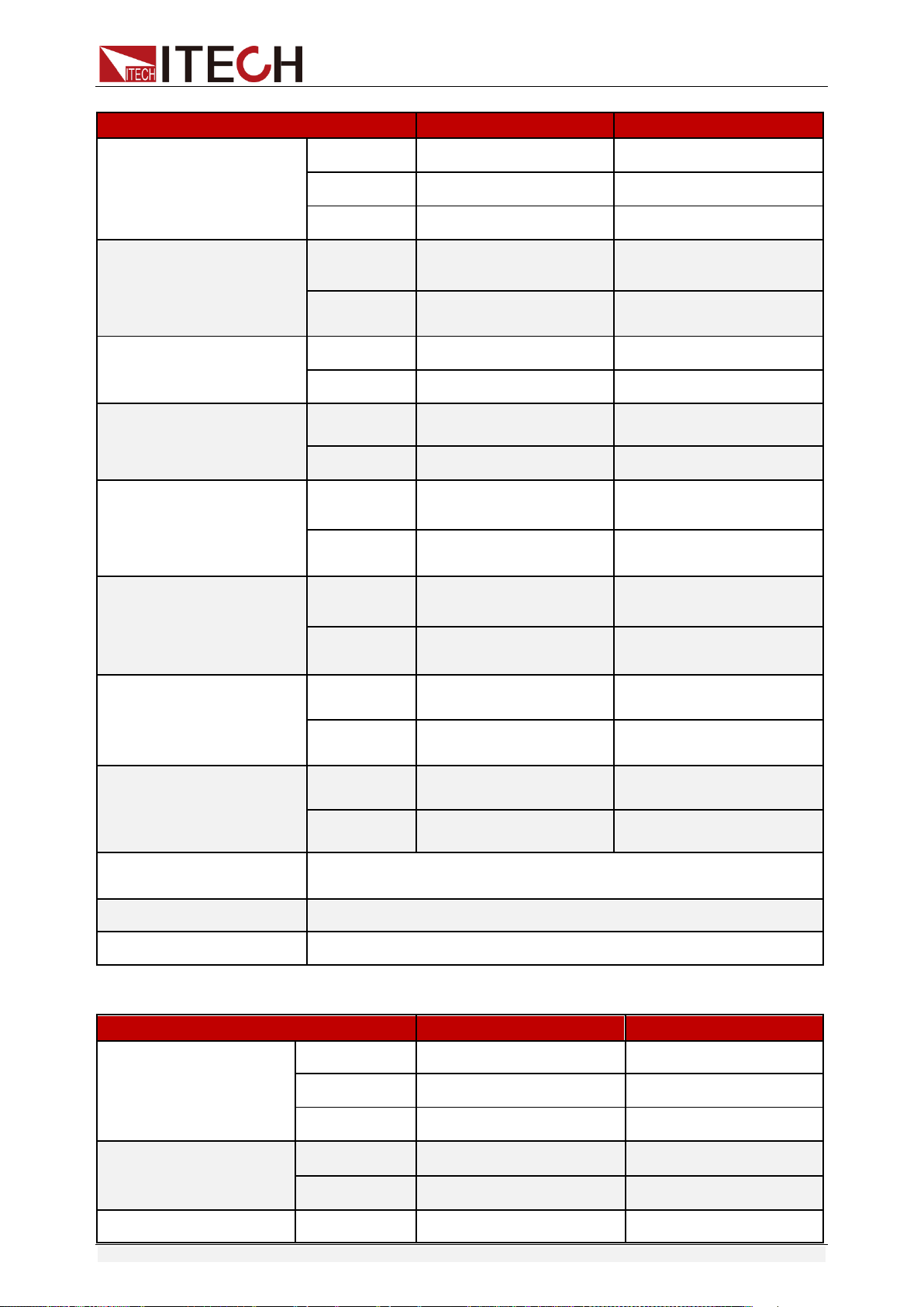
Parameters
IT6922B
IT6932B
Rated values
(0 °C~40 °C)
voltage
0~60V
0~60V
current
0~5A
0~10A
Power
100W
200W
Load regulation
(%of output+offset)
voltage
≤0.01%+3mV
≤0.01%+10mV
current
≤0.05%+2mA
≤0.05%+4mA
Line regulation
±( %of output+offset)
voltage
≤0.01%+3mV
≤0.01%+10mV
current
≤0.05%+2mA
≤0.05%+4mA
Setup resolution
voltage
1mV
1mV
current
0.1mA
1mA
Readback resolution
voltage
1mV
1mV
current
0.1mA
1mA
Setup accuracy
(within twelve months)
(25°C±5°C)
(%of output+offset)
voltage
≤0.03%+5mV
≤0.03%+5mV
current
≤0.1%+5mA
≤0.1%+10mA
Read back resolution
(W) (25°C±5°C)
(%of output+offset)
voltage
≤0.03%+5mV
≤0.03%+5mV
current
≤0.1%+5mA
≤0.1%+10mA
Ripple
(20Hz ~20MHz)
voltage
≤5mVp-p
≤8mVp-p
current
≤5mArms
≤6mArms
Sample rate
10HZ
Dimension (mm)
214.5mmW×88.2mmH×354.6mmD
Weight (net)
7.7Kg
Parameters
IT6942B
IT6952B
Rated values
(0 °C~40 °C)
voltage
0~60V
0~60V
current
0~15A
0~25A
Power
360W
600W
Load regulation
(%of output+offset)
voltage
≤0.01%+30mV
≤0.01%+30mV
current
≤0.05%+6mA
≤0.1%+10mA
Line regulation
voltage
≤0.01%+30mV
≤0.01%+30mV
Technical Specification
Copyright ©ITECH Electronic Co., Ltd. 35
Parameters
IT6942B
IT6952B
±( %of output+offset)
current
≤0.05%+6mA
≤0.1%+10mA
Setup resolution
voltage
1mV
1mV
current
0.1mA
0.1mA
Readback resolution
voltage
1mV
1mV
current
0.1mA(<10A)
1mA(>10A)
0.1mA(<10A)
1mA(>10A)
Setup accuracy
(within twelve months)
(25°C±5°C)
(%of output+offset)
voltage
≤0.03%+5mV
≤0.03%+5mV
current
≤0.1%+15mA
≤0.1%+25mA
Read back resolution
(W) (25°C±5°C)
(%of output+offset)
voltage
≤0.03%+5mV
≤0.03%+5mV
current
≤0.1%+15mA
≤0.1%+25mA
Ripple
(20Hz ~20MHz)
voltage
≤15mVp-p
≤20mVp-p
current
≤8mArms
≤15mArms
Rise time
voltage
≤150mS(10%-90%)
≤150mS(10%-90%)
Fall time
voltage
≤2S(10%-90%)
≤2S(10%-90%)
Sample rate
10HZ/S
10HZ/S
Dimension (mm)
214.5mmW×88.2mmH×354.6mmD
214.5mmW×88.2mmH×
445mmD
Weight (net)
7.7Kg
15Kg
Parameters
IT6953B
Rated values
( 0 °C~40 °C)
voltage
0~150V
current
0~10A
power
600W
Load regulation
(%of output+offset)
voltage
≤0.01%+25mV
current
≤0.5%+10mA
Line regulation
(%of output+offset)
voltage
≤0.01%+25mV
current
≤0.5%+10mA
Setup resolution
voltage
1mV(<100V) 10mV(≥100V)
current
0.1mA
Readback resolution
voltage
1mV(<100V) 10mV(≥100V)
current
0.1mA
Setup accuracy
(within twelve
months) (25°C±5°C)
(%of output+offset)
voltage
≤0.03%+20mV
current
≤0.1%+25mA
Technical Specification
Copyright ©ITECH Electronic Co., Ltd. 36
*The above specifications may be subject to change without prior notice.
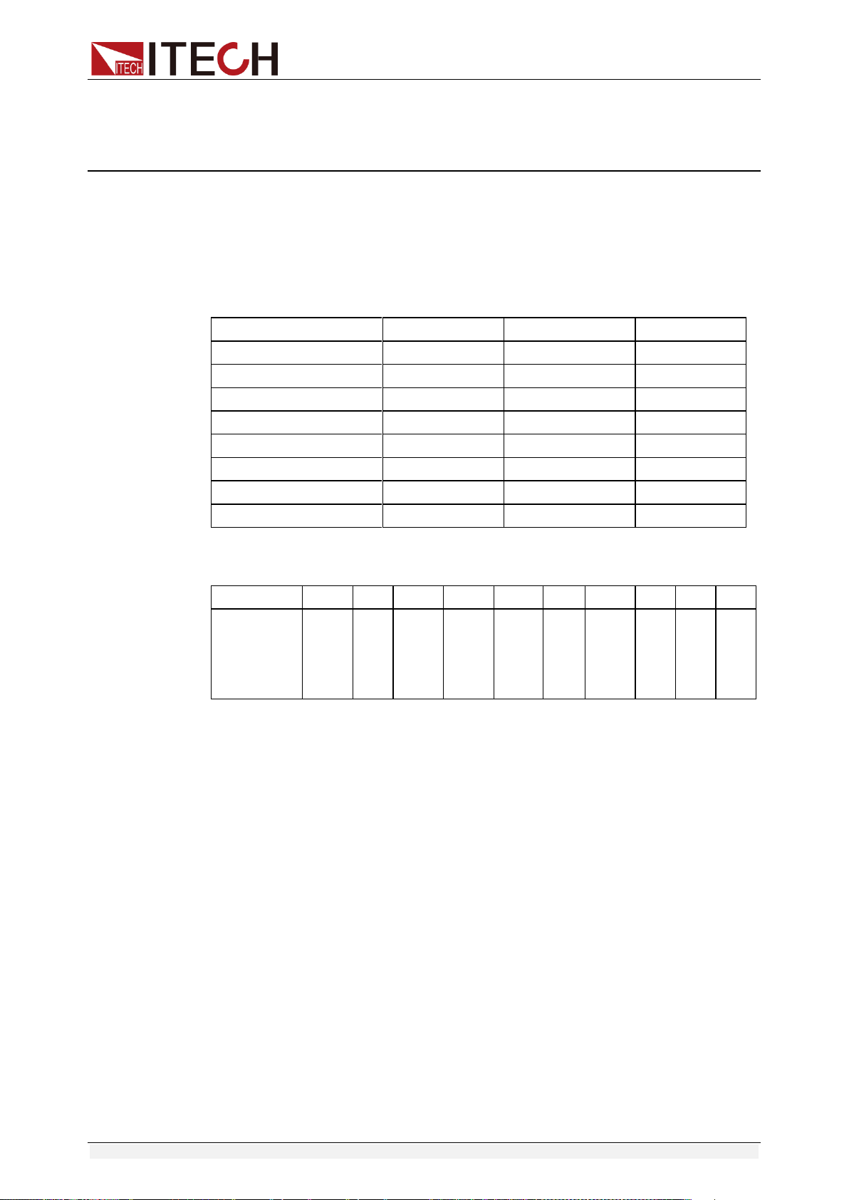
5.2 Supplemental Characteristics
State storage capacity: 9×8 Groups
Recommended calibration frequency: once a year
Cooling style: fans
Maximum input power:
Model
Maximum input power
Model
Maximum input power
IT6922A
350VA
IT6942A
1000VA
IT6932A
550VA
IT6952A
2000VA
IT6933A
550VA
IT6953A
2000VA
IT6922B
350VA
IT6932B
550VA
IT6942B
1000VA
IT6952B
2000VA
IT6953B
2000VA
-
-
Read back resolution
(W) (25°C±5°C)
(%of output+offset)
voltage
≤0.03%+20mV
current
≤0.1%+25mA
Ripple
(20Hz ~20MHz)
voltage
≤50mVp-p
current
≤15mArms
Rise time
voltage
≤150mS(10%-90%)
Fall time
voltage
≤7S(90%-10%)
Transient
Response Time
voltage
0.2mS
Sample rate
10HZ/S
Dimension(mm)
214.5mmW×88.2mmH×445mmD
Weight (net)
15Kg
Appendix
Copyright ©ITECH Electronic Co., Ltd. 37
Appendix
Specifications of Red and Black Test Lines
ITECH provides you with optional red and black test lines, which individual
sales and you can select for test. For specifications of ITECH test lines and
maximum current values, refer to the table below.
Model
Specification
Cross section
Length
IT-E301/10A
10A
-
1m
IT-E301/30A
30A
6mm
2
1.2m
IT-E301/30A
30A
6mm
2
2m
IT-E301/60A
60A
20mm
2
1.5m
IT-E301/120A
120A
50mm
2
2m
IT-E301/240A
240A
70mm
2
1m
IT-E301/240A
240A
70mm
2
2m
IT-E301/360A
360A
95mm
2
2m
For maximum current of AWG copper wire, refer to table blow.
AWG
10
12
14
16
18
20
22
24
26
28
The
Maximum
current
value( A)
40
25
20
13
10
7
5
3.5
2.5
1.7
Note: AWG ( American Wire Gage), it means X wire ( marked on the wire). The
table above lists current capacity of single wire at working temperature of 30°C.
For reference only.

Contact Us
Thanks for purchasing ITECH products. In case of any doubts, please contact us as follows:
1. Refer to accompanying data disk and relevant manual.
2. Visit ITECH website:www.itechate.com
3. Select the most convenient contact method, for further information.