High Speed and High Accuracy
Programmable Power Supply
Series IT6100B User’s Manual
Model: IT6121B/IT6122B/IT6123B/IT6132B/
IT6133B/IT6162B/IT6164B
Version: V1.1

IT6100B User’s Manual
Notices
© Itech Electronic, Co., Ltd. 2018
No part of this manual may be
reproduced in any form or by any means
(including electronic storage and
retrieval or translation into a foreign
language) without prior permission and
written consent from Itech Electronic,
Co., Ltd. as governed by international
copyright laws.
Manual Part Number
IT6100B-402198
Revision
1st Edition: Apr. 8, 2018
Itech Electronic, Co., Ltd.
Trademarks
Pentium is U.S. registered trademarks
of Intel Corporation.
Microsoft, Visual Studio, Windows and
MS Windows are registered trademarks
of Microsoft Corporation in the United
States and/or other countries and
regions.
Warranty
The materials contained in this
document are provided “as is”, and
is subject to change, without prior
notice, in future editions. Further, to
the maximum extent permitted by
applicable laws, ITECH disclaims
all warrants, either express or
implied, with regard to this manual
and any information contained
herein, including but not limited to
the implied warranties of
merchantability and fitness for a
particular purpose. ITECH shall
not be held liable for errors or for
incidental or indirect damages in
connection with the furnishing, use
or application of this document or of
any information contained herein.
Should ITECH and the user enter
into a separate written agreement
with warranty terms covering the
materials in this document that
conflict with these terms, the
warranty terms in the separate
agreement shall prevail.
Technology Licenses
The hardware and/or software
described herein are furnished under a
license and may be used or copied only
in accordance with the terms of such
license.
Restricted Rights Legend
Restricted permissions of the U.S.
government. Permissions for software
and technical data which are authorized
to the U.S. Government only include
those for custom provision to end users
ITECH provides this customary
commercial license in software and
technical data pursuant to FAR 12.211
(Technical Data) and 12.212 (Computer
Software) and, for the Department of
Defense, DFARS 252.227-7015
(Technical Data – Commercial Items)
and DFARS 227.7202-3 (Rights in
Commercial Computer Software or
Computer Software Documentation).
Safety Notices
A CAUTION sign denotes a
hazard.
It calls attention to an operating
procedure or practice that, if not
correctly performed or adhered
to, could result in damage to the
product or loss of important data.
Do not proceed beyond a
CAUTION sign until the
indicated conditions are fully
understood and met.
A WARNING sign denotes a
hazard. It calls attention to an
operating procedure or practice
that, if not correctly performed
or adhered to, could result in
personal injury or death. Do not
proceed beyond a WARNING
sign until the indicated
conditions are fully understood
and met.
NOTE
A NOTE sign denotes important
hint. It calls attention to tips or
supplementary information that
is essential for users to refer to.
IT6100B User’s Manual
Copyright © ITECH Electronic Co., Ltd. i
Quality Certification and Assurance
We certify that IT6100B series power supply meets all the published specifications.
Warranty
ITECH warrants that the product will be free from defects in material and
workmanship under normal use for a period of one (1) year from the date of
delivery (except those described in the Limitation of Warranty below).
For warranty service or repair, the product must be returned to a service center
designated by ITECH.
The product returned to ITECH for warranty service must be shipped
PREPAID. And ITECH will pay for return of the product to customer.
If the product is returned to ITECH for warranty service from overseas, all the
freights, duties and other taxes shall be on the account of customer.
Limitation of Warranty
This Warranty will be rendered invalid if the product is:
Damage caused by circuit installed by customer or using customer own
products or accessories;
Modified or repaired by customer without authorization;
Damage caused by circuit installed by customer or not operating our products
under designated environment;
The product model or serial number is modified, deleted, removed or illegible;
Damaged as a result of accidents, including but not limited to lightning,
moisture, fire, improper use or negligence.
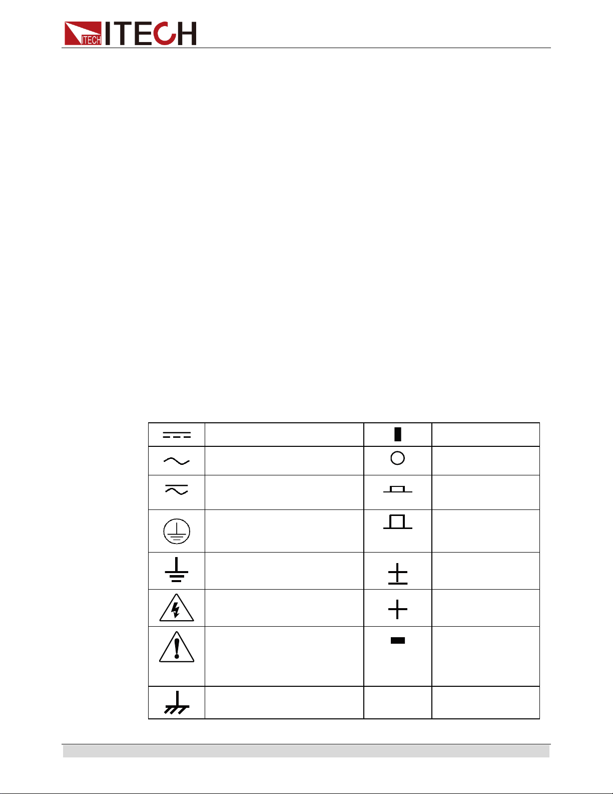
Safety Symbols
Direct current
ON (power on)
Alternating current
OFF (power off)
Both direct and alternating
current
Power-on state
Protective conductor terminal
Power-off state
Earth (ground) terminal
Reference terminal
Caution, risk of electric shock
Positive terminal
Warning, risk of danger (refer
to this manual for specific
Warning or Caution
information)
Negative terminal
Frame or chassis terminal
-
-

IT6100B User’s Manual
Copyright © ITECH Electronic Co., Ltd. ii
Safety Precautions
The following safety precautions must be observed during all phases of operation
of this instrument. Failure to comply with these precautions or specific warnings
elsewhere in this manual will constitute a default under safety standards of design,
manufacture and intended use of the instrument. ITECH assumes no liability for
the customer’s failure to comply with these precautions.
Do not use the instrument if it is damaged. Before operation, check the casing
to see whether it cracks. Do not operate the instrument in the presence of
inflammable gasses, vapors or dusts.
The power supply is provided with a three-core power line during delivery and
should be connected to a three-core junction box. Before operation, be sure
that the power supply is well grounded. Make sure to use the power cord
supplied by ITECH.
Check all marks on the instrument before connecting the instrument to power
supply.
Use electric wires of appropriate load. All loading wires should be capable of
bearing maximum short-circuit of electronic load without overheating. If there
are multiple loads, each pair of the load power cord must be carry out the full
rated short-circuit output current of the power securely.
Ensure the voltage fluctuation of mains supply is less than 10% of the working
voltage range in order to reduce risks of fire and electric shock.
Do not install alternative parts on the instrument or perform any unauthorized
modification.
Do not use the instrument if the detachable cover is removed or loosen.
To prevent the possibility of accidental injuries, be sure to use the power
adapter supplied by the manufacturer only.
We do not accept responsibility for any direct or indirect financial damage or
loss of profit that might occur when using the instrument.
This instrument is used for industrial purposes, do not apply this product to IT
power supply system.
Never use the instrument with a life-support system or any other equipment
subject to safety requirements.
Failure to use the instrument as directed by the manufacturer may render its
protective features void.
Always clean the casing with a dry cloth. Do not clean the internals.
Make sure the vent hole is always unblocked.
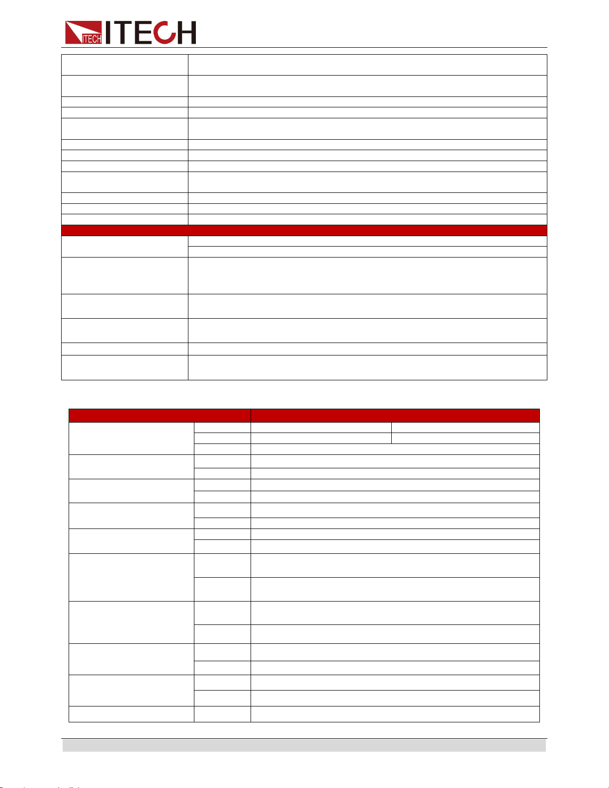
Environmental Conditions
The instrument is designed for indoor use and an area with low condensation. The
table below shows the general environmental requirements for the instrument. The
speed of fan will change intelligently by the temperature of radiator. When the
temperature is up to 40°C, the fan will be on and adjust intelligently when
temperature changes.
IT6100B User’s Manual
Copyright © ITECH Electronic Co., Ltd. iii
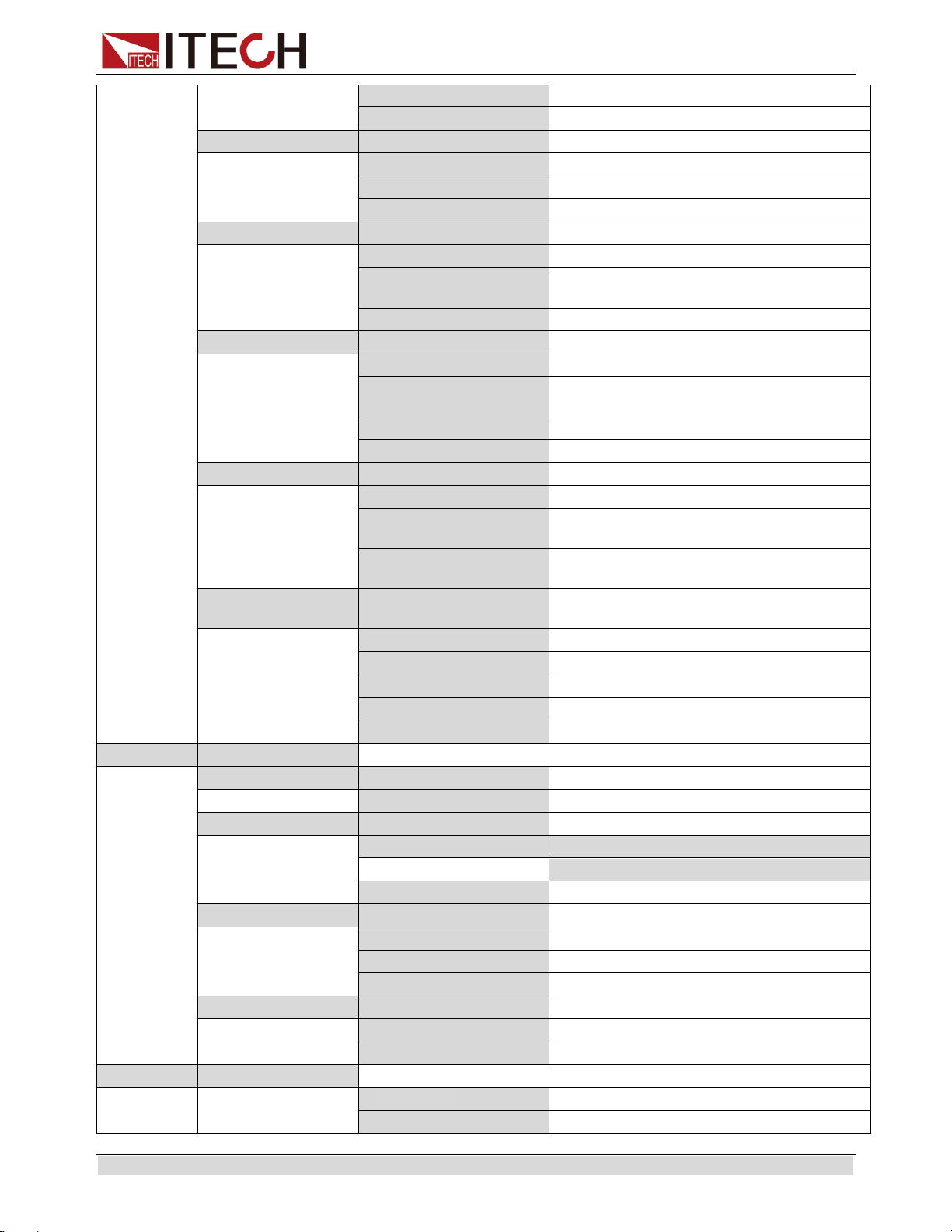
Environmental Conditions
Requirements
Operating temperature
0°C to 40°C
Operating humidity
20%-80% (non-condensation)
Storage temperature
-20°C to 70 °C
Altitude
≤2,000m
Pollution degree
Pollution degree 2
Installation category
Ⅱ
NOTE
To make accurate measurements, allow the instrument to warm up for 30 min before
operation.
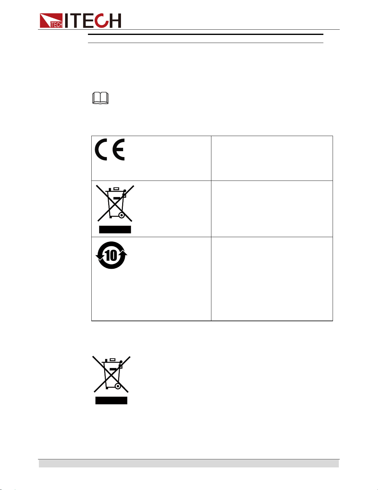
Regulatory Markings
The CE mark is a registered
trademark of the European
Community. This CE mark shows that
the product complies with all the
relevant European Legal Directives.
The instrument complies with the
WEEE Directive (2002/96/EC)
marking requirement. This affixed
product label indicates that you must
not discard the electrical/electronic
product in domestic household waste.
This symbol indicates the time period
during which no hazardous or toxic
substances are expected to leak or
deteriorate during normal use. The
expected service life of the product is
10 years. The product can be used
safely during the 10-year Environment
Friendly Use Period (EFUP). Upon
expiration of the EFUP, the product
must be immediately recycled.
Waste Electrical and Electronic Equipment (WEEE)
Directive
2002/96/EC Waste Electrical and Electronic Equipment
(WEEE) Directive
This product complies with the WEEE Directive (2002/96/EC)
marking requirement. This affix product label indicates that you
must not discard the electrical/electronic product in domestic
household waste.
Product Category
With reference to the equipment classifications described in the
Annex I of the WEEE Directive, this instrument is classified as a
“Monitoring and Control Instrument” product.
To return this unwanted instrument, contact your nearest ITECH
office.

IT6100B User’s Manual
Copyright © ITECH Electronic Co., Ltd. iv
Compliance Information
Complies with the essential requirements of the following applicable European
Directives, and carries the CE marking accordingly:
Electromagnetic Compatibility (EMC) Directive 2014/30/EU
Low-Voltage Directive (Safety) 2014/35/EU
Conforms with the following product standards:
EMC Standard
IEC 61326-1:2012/ EN 61326-1:2013 ¹²³
Reference Standards
CISPR 11:2009+A1:2010/ EN 55011:2009+A1:2010 (Group 1, Class A)
IEC 61000-4-2:2008/ EN 61000-4-2:2009
IEC 61000-4-3:2006+A1:2007+A2:2010/ EN 61000-4-3:2006+A1:2008+A2:2010
IEC 61000-4-4:2004+A1:2010/ EN 61000-4-4:2004+A1:2010
IEC 61000-4-5:2005/ EN 61000-4-5:2006
IEC 61000-4-6:2008/ EN 61000-4-6:2009
IEC 61000-4-11:2004/ EN 61000-4-11:2004
1. The product is intended for use in non-residential/non-domestic environments. Use of the
product in residential/domestic environments may cause electromagnetic interference.
2. Connection of the instrument to a test object may produce radiations beyond the specified limit.
3. Use high-performance shielded interface cable to ensure conformity with the EMC standards
listed above.
Safety Standard
IEC 61010-1:2010/ EN 61010-1:2010

IT6100B User’s Manual
Copyright © ITECH Electronic Co., Ltd. v
CONTENTS
Quality Certification and Assurance....................................................................................................... i
Warranty ................................................................................................................................................. i
Limitation of Warranty ............................................................................................................................ i
Safety Symbols ...................................................................................................................................... i
Safety Precautions ................................................................................................................................ ii
Environmental Conditions ..................................................................................................................... ii
Regulatory Markings ............................................................................................................................. iii
Waste Electrical and Electronic Equipment (WEEE) Directive ............................................................ iii
Compliance Information ....................................................................................................................... iv
Chapter1 Inspection and Installation .................................................................................. 1
1.1 Verifying the Shipment .................................................................................................................... 1
1.2 Instrument Size Introduction ........................................................................................................... 1
1.3 Rack Mounting ................................................................................................................................ 4
1.4 Connecting the Power Cord ........................................................................................................... 4
1.5 Connecting Test Lines (Optional) ................................................................................................... 5
Chapter2 Quick Reference ................................................................................................ 8
2.1 Breief Introduction ........................................................................................................................... 8
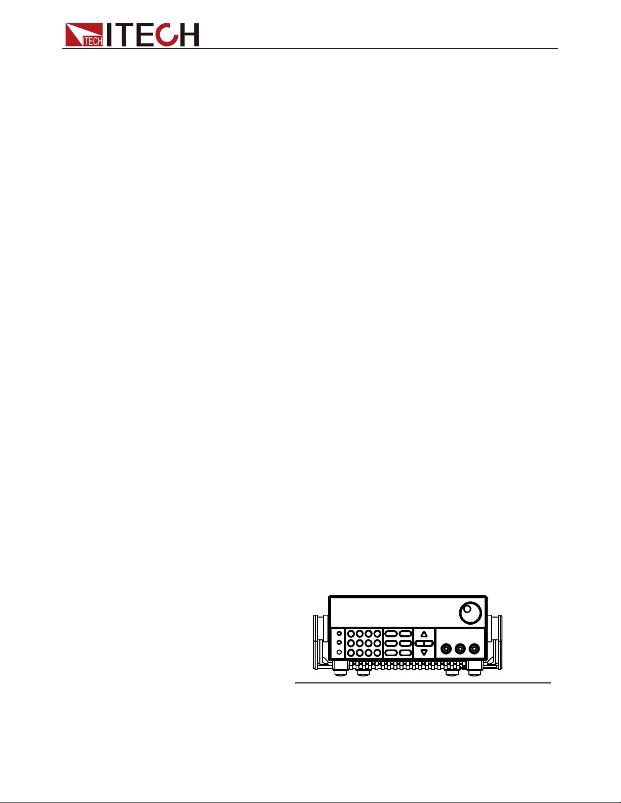
2.2 Front Panel Introduction ................................................................................................................. 9
2.3 Rear Panel Introduction ................................................................................................................ 10
2.4 Keyboard Introduction................................................................................................................... 12
2.5 Function description of VFD status indicators .............................................................................. 13
2.6 Power-on self-test ......................................................................................................................... 13
Chapter3 Basic operation ................................................................................................ 16
3.1 Local/Remote Mode ...................................................................................................................... 16
3.2 Setting the Voltage ........................................................................................................................ 16
3.3 Setting the Current ........................................................................................................................ 17
3.4 On/Off Operation .......................................................................................................................... 17
3.5 Set mode and Meter mode ........................................................................................................... 18
3.6 CC and CV .................................................................................................................................... 18
3.7 Save and recall operation ............................................................................................................. 18
3.8 Trigger operation ........................................................................................................................... 19
3.9 Menu Operation ............................................................................................................................ 19
3.10 OVP ............................................................................................................................................ 27
3.11 Key Lock ..................................................................................................................................... 27
3.12 Terminals at rear panel ............................................................................................................... 27
3.13 Power information ....................................................................................................................... 31
Chapter4 Specification ..................................................................................................... 32
4.1 Specification .................................................................................................................................. 32
Chapter5 Remote Operation Mode .................................................................................. 36
5.1 RS232 interface ............................................................................................................................ 36
5.2 USB interface ................................................................................................................................ 37
5.3 GPIB interface .............................................................................................................................. 38
5.4 Communication protocol ............................................................................................................... 38
Appendix ............................................................................................................................. 39
Specifications of Red and Black Test Lines ........................................................................................ 39
Inspection and Installation
Copyright © ITECH Electronic Co., Ltd. 1
Chapter1 Inspection and Installation
1.1 Verifying the Shipment
Unpack the box and check the contents before operating the instrument. If wrong
items have been delivered, if items are missing, or if there is a defect with the
appearance of the items, contact the dealer from which you purchased the
instrument immediately. The package contents include:
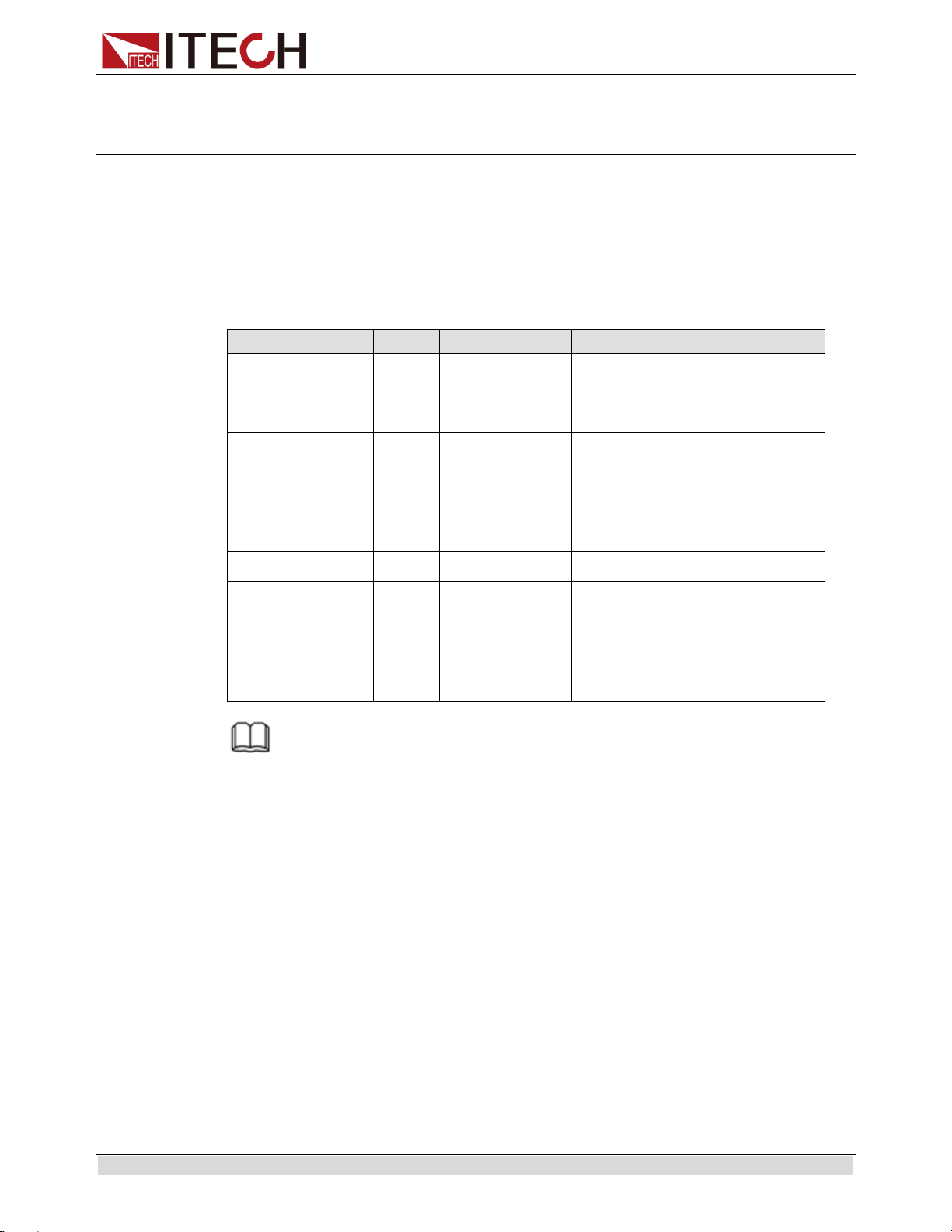
Checklist of Package Contents
Item
Qty.
Model
Remarks
IT6100B power
supply
x1
IT6100B series
The IT6100B series include:
IT6121B/IT6122B/IT6123B/
IT6132B/IT6133B/IT6162B/
IT6164B
Power cord
x1
IT-E171/IT-E17
2/IT-E173/IT-E
174
User may select an appropriate
power cord that matches the
specifications of power socket
used in the area. See the
Section Connecting the
Power Cord for details.
USB cable
x1
-
-
CD
x1
-
It contains IT6100B power
supply User’s Manual,
Programming Guide and other
user documentations.
Ex-factory Test
Report
x1
-
It is the test report of the
instrument before delivery.
NOTE
After confirming that package contents are consistent and correct, please appropriately keep
package box and related contents. The package requirements should be met when the
instrument is returned to factory for repair.
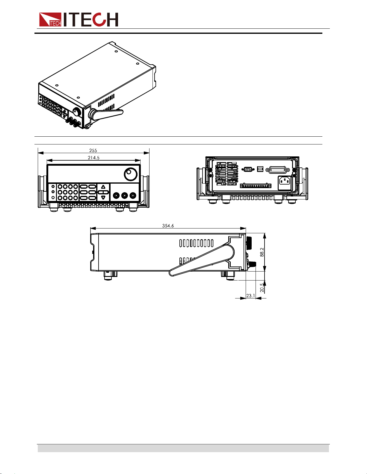
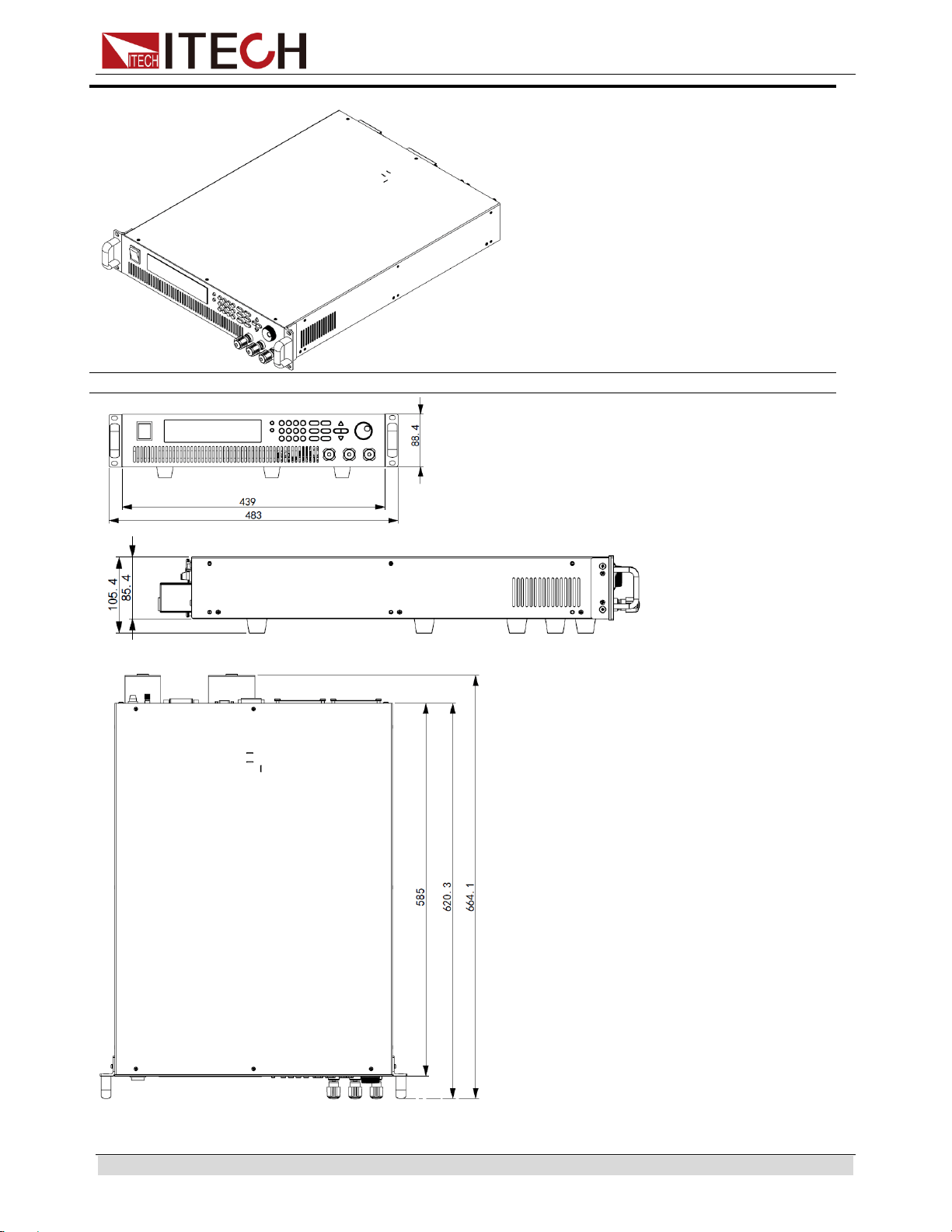
1.2 Instrument Size Introduction
The instrument should be installed at well-ventilated and rational-sized space.
Please select appropriate space for installation based on the electronic load size.
IT6100B series power supply different models are not the same size; the detail size
of the power supply is shown as below.
Inspection and Installation
Copyright © ITECH Electronic Co., Ltd. 2
IT6121B/IT6122B/IT6123B/IT6132B/IT6133B Models
Detailed Dimension Drawing
Inspection and Installation
Copyright © ITECH Electronic Co., Ltd. 3
IT6162B/IT6164B Models
Detailed Dimension Drawing
Inspection and Installation
Copyright © ITECH Electronic Co., Ltd. 4
1.3 Rack Mounting
IT6100B series can be mounted on a standard rack. ITECH provides user with
IT-E151 or IT-E151A rack, as a mount kit. The detailed operation please refer to the
User Manual of your mount kit.
1.4 Connecting the Power Cord
Connect power cord of standard accessories and ensure that the power supply is
under normal power supply.
AC power input level
Working voltage for IT6121B/IT6122B/IT6123B/IT6132B/IT6133B/IT6162B is 110V
and 220V; Working voltage for IT6164B is 220V, so please pay attention to the
working input voltage.
AC power input level:
Option Opt.01: 220VAC ± 10%, 47 to 63 Hz
Option Opt.02: 110 VAC ± 10%, 47 to 63 Hz
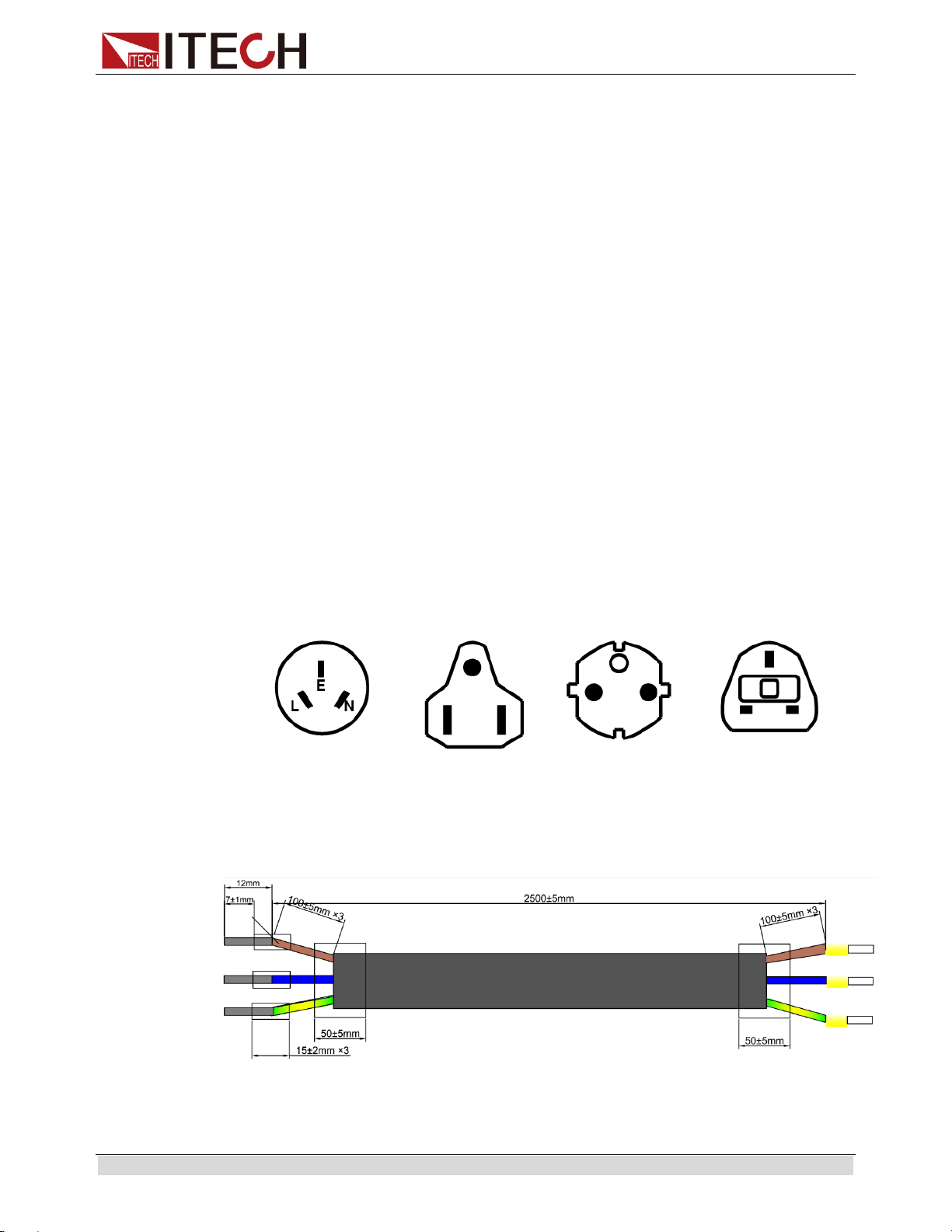
Categories of power cords
IT6121B/IT6122B/IT6123B/IT6132B/IT6133B provides the standard power
cords as below.
Please select appropriate power cords appropriate to local voltage based on
the specifications of power cords below. If purchased model fails to meet local
voltage requirements, please contact distributor or factory for change.
China
IT-171
America, Canada,
Japan
IT-E172
Europe
IT-E173
Britain
IT-E174
IT6162B/IT6164B provides the standard power cords as below.
Inspection and Installation
Copyright © ITECH Electronic Co., Ltd. 5
The power cords supplied with this product is certified for safety. In case the
supplied lines assembly needs to be replaced, or an extension lines must be added,
be sure that it can meet the required power ratings of this product. Any misuse
voids the warranty of this product.
Connecting AC Input
IT6121B/IT6122B/IT6123B/IT6132B/IT6133B Connect standard power cord to
the power supply input terminal.
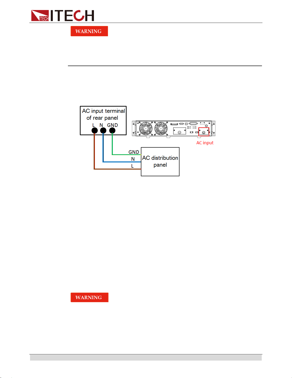
IT6162B/IT6164B AC input connector as follows.
1. In the above illustration, one end of the AC power cord is connected to the
AC input terminal in the rear panel of the power supply.
Connect the wire, zero line and ground to the corresponding terminal of the
device. Before inserting, please loose the screw, lock the screw when it is
inserted.
2. Connect the three terminals brown to line (L), blue to neutral (N), and
yellow-green to ground (G) on the other end of the power cord to your AC
distribution panel.
1.5 Connecting Test Lines (Optional)
Test lines are not standard accessories of the instrument. Please select optional
red and black test lines for individual sales based on the maximum current value.
For specifications of test lines and maximum current values, refer to “Specifications
of Red and Black Test Lines” in “Appendix”.
Before connecting test lines, be sure to switch off the instrument. Power
switch is in Off position. Otherwise, contact with output terminals in rear
panel may cause electrical shock.
To avoid electrical shock, before testing, please make sure the rating
values of the testing lines, and do not measure the current that higher
than the rating value. All test lines shall be capable of withstanding the
maximum short circuit output current of the power supply without

Inspection and Installation
Copyright © ITECH Electronic Co., Ltd. 6
causing overheat.
If several loads are provided, each pair of load wires shall safely
withstand the rated short circuit output current of the power supply
under full load.
Always use test lines provided by ITECH to connect the equipment. If test
lines from other factories are used, please check that the test line can
withstand maximum current.
During wiring, check that the anode and cathode of the test lines are
properly and tightly connected; anode ON and cathode OFF are
prohibited.
Introduction of Binding Posts
The maximum rated current of the terminal at position (A) is the maximum rated
output current of the instrument. Securely fasten all wires by hand-tightening the
binding posts. You can also insert standard banana plugs into the front of the
connectors as shown in (B), and the maximum rated current at (B) is 10 A.
IT6121B/IT6122B/IT6123B/IT6132B/IT6133B
IT6162B/IT6164B
Connecting the DUT
Test line connection is given below taking local measurement as example. For
details of local and remote measurements, refer to “Terminals at rear panel”.
1. Before connecting the test lines, be sure that the instrument Power is in Off
position.
2. Check whether the shorting clip of Sense terminal is correctly mounted.
3. Unscrew the screws of the output terminals and connect the red and black test
lines to the output terminals. Re-tighten the screws.
When maximum current that one test line can withstand fails to meet the
current rated current, use several pieces of red and black test lines. For
example, the maximum current is 1,200A, then 4 pieces of 360A red and black
lines are required.

Inspection and Installation
Copyright © ITECH Electronic Co., Ltd. 7
4. Directly connect the other end of the red and black lines to the DUT terminal.

Quick Reference
Copyright © ITECH Electronic Co., Ltd. 8
Chapter2 Quick Reference
2.1 Brief Introduction
IT6100B Series power supplies are high resolution and high speed programmable
DC power supplies. The Series power supplier has fast voltage rise speed and
very high accuracy and resolution. Also configure with standard RS232/ USB/GPIB
interface to realize fast communication speed. The Series power supplier has
remote sense function to compensate line voltage loss from power to determinand.
List configure can operated on front panel. At the same time, the Series power
supplier has voltage meter and ohmmeter function in order to facility test. This
series offer flexible solution to general laboratory and workshop requirement. This
series of power with international advanced level, the main special functions and
advantages as follows:
VFD display
Luminiferous LED key
Convenient data entry via knob or numerical key pad
Use cursor adjusting step value
Very high accuracy and resolution of 0.1mV/0.1mA
Hold during Power off memory function.
Capable output wave based on edit voltage/current with time variations (List
Mode)
High voltage rise speed (<20mS)
Memory capacity: 100 groups
On time output function, time range 0.01 to 60000S
Remote sense interface to compensate line voltage, increase output accuracy.
External analog signal control the power input and output
Equipped with 5
2
1
digital m
meter
Low ripple and noise
Intelligent fan control to saving energy and reducing noise.
Standard dimension, capable to installed in standard cabinet with IT-E151,
Configure with Standard communication interface RS232/USB/GPIB, 25ms
communication speed.
Rich SCPI commands, convenient to build intelligent test platform.
Provide free remote control software with strong function saving secondary
development time.
Model
Voltage
current
Power
IT6121B
20V
5A
100W
IT6122B
32V
3A
96W
IT6123B
72V
1.2A
86.4W
IT6132B
30V
5A
150W
Quick Reference
Copyright © ITECH Electronic Co., Ltd. 9
IT6133B
60V
2.5A
150W
IT6162B
20V
50A
1000W
IT6164B
30V/60V
40A/20A
1200W
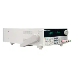
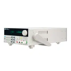
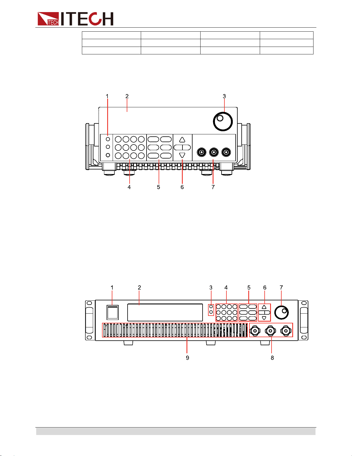
2.2 Front Panel Introduction
Front panel of IT6121B/IT6122B/IT6123B/IT6132B/IT6133B.
1. Shift, Local and Power
2. VFD display
3. Rotary knob
4. Numeric keys, esc button
5. Function keys
6. up/down, left/right key
7. output terminals
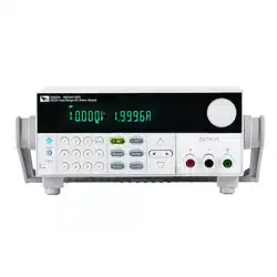
Front panel of IT6162B/IT6164B.
1. Power switch
2. VFD display
3. Shift and Local key
4. Numeric keys, esc button
5. Function keys
6. up/down, left/right key
Quick Reference
Copyright © ITECH Electronic Co., Ltd. 10
7. Rotary knob
8. output terminals
9. Vent hole
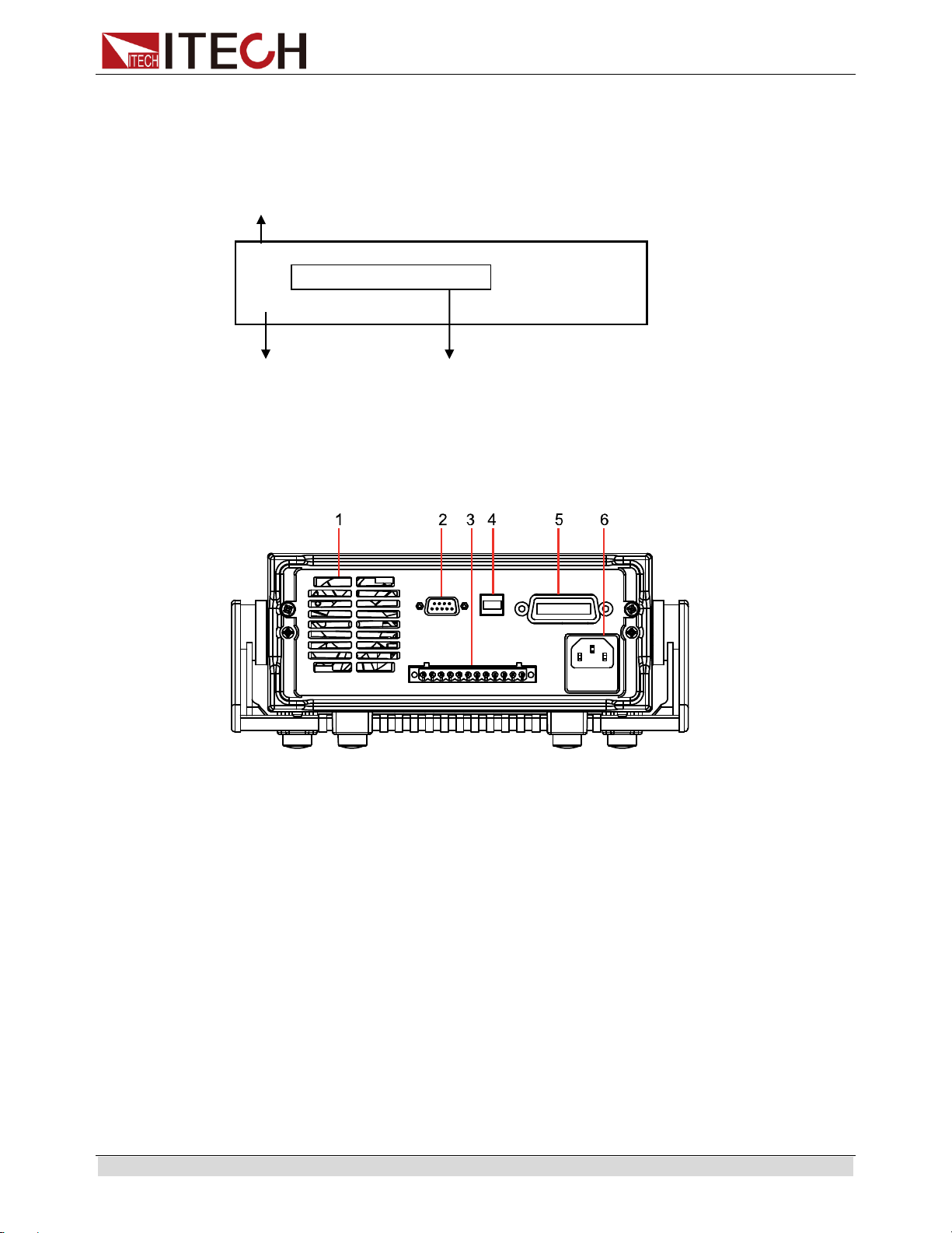
2.3 Rear Panel Introduction
Rear panel of IT6121B/IT6122B/IT6123B/IT6132B/IT6133B.
1. Ventilation holes
2. RS232 interface
3. Quick connect terminal for remote sensing and DVM terminal and external
control port
4. USB interface
5. GPIB interface
6. AC power inlet and fuse compartment
Rear panel of IT6162B.
OFF
1.000V 1.0000A
0.0001V
Value measured
by DVM.
The actual output voltage
value and current.
VFD display
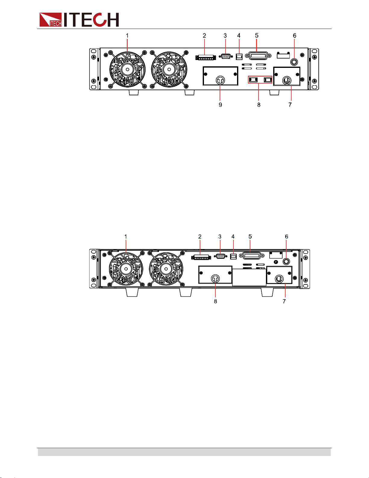
Quick Reference
Copyright © ITECH Electronic Co., Ltd. 11
1. Ventilation holes
2. DVM terminal and external control port
3. RS232 interface
4. USB interface
5. GPIB interface
6. Fuse
7. AC power inlet
8. AC power selection switch
9. Output terminals and quick connect terminal for remote sensing
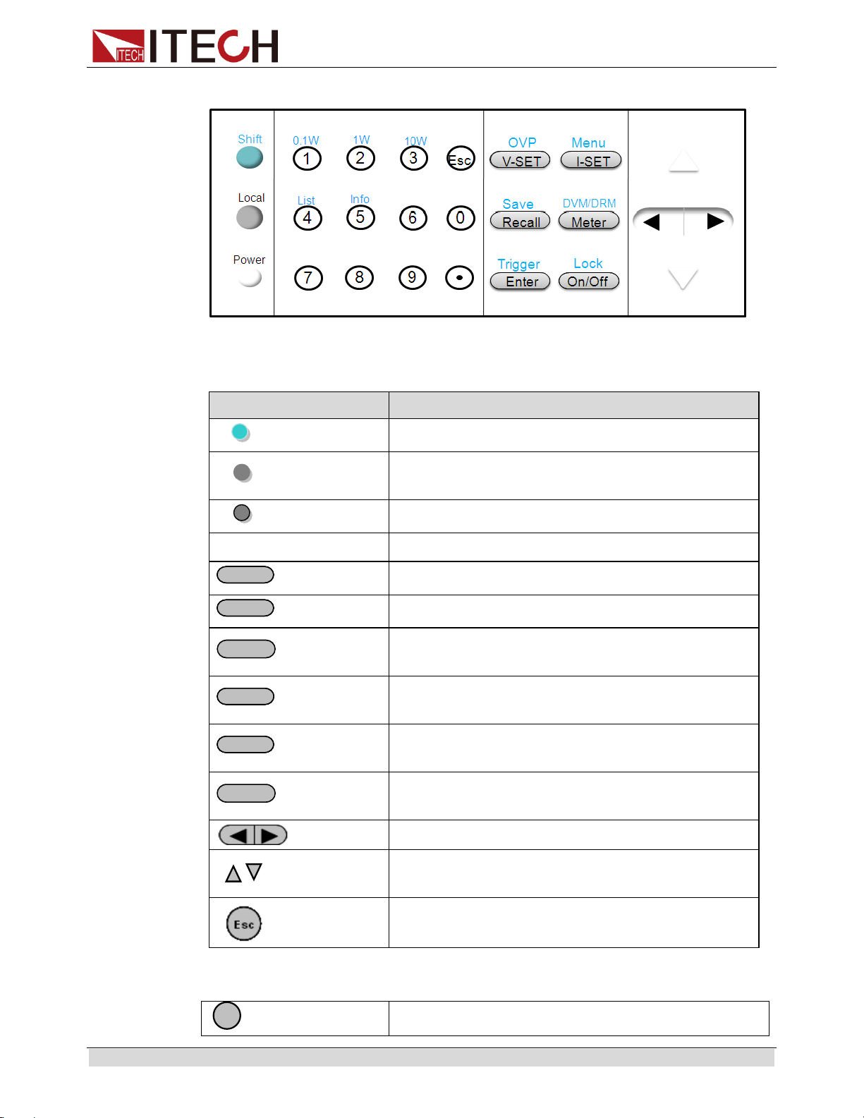
Rear panel of IT6164B.
1. Ventilation holes
2. DVM terminal and external control port
3. RS232 interface
4. USB interface
5. GPIB interface
6. Fuse
7. AC power inlet
8. Output terminals and quick connect terminal for remote sensing
Quick Reference
Copyright © ITECH Electronic Co., Ltd. 12
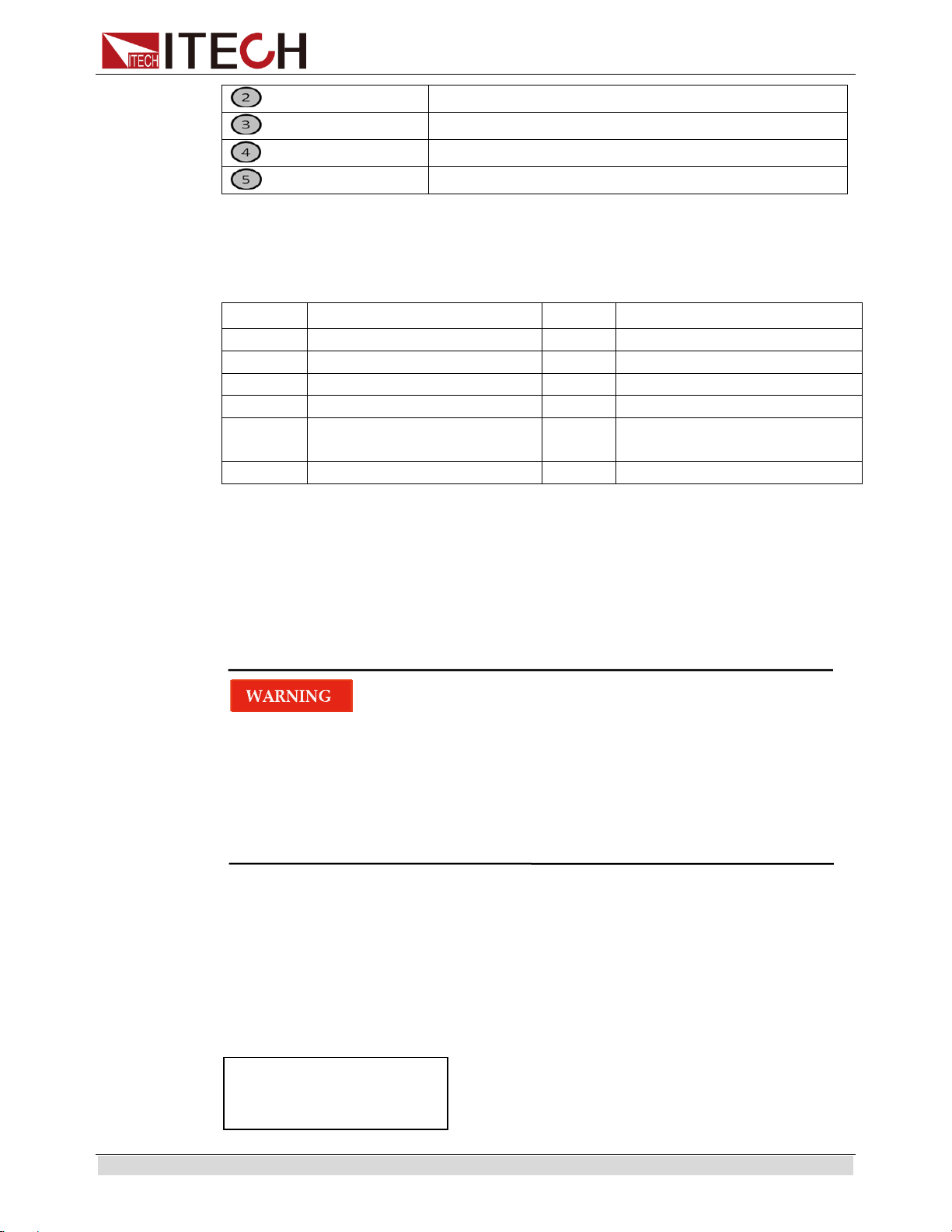
2.4 Keyboard Introduction
The functions of keys on the front panel of the IT6100B series power supply are
shown in the following table.
Key tag
Name and function
Shift
Use to access secondary functions
Local
Enable front panel operation when in remote
mode
Power
Power switch
0-9
Numerical keys for direct entry of values
V-setV-set
OVP
Set the voltage value, OVP value
I-setI-set
Menu
Set the current value and enter into the menu
Recall
Save
Recall(Save) operating data from internal
memory
MeterMeter
DVM/DRM
Switch between Setting/Meter display, also
used to switch to DVM/DRM measuring state.
EnterEnter
Trigger
Press to confirm numerical entries, or provide a
trigger signal
On/Off
Lock
Set the output state of the power supply, or to
lock the front-panel keys
Right/left keys to adjust the position of cursor
Up/down key to overturn the menu items or
increase/decrease the setting value.
Quit the operation
Numerical keys/Secondary Shift Functions:
1
(0.1W)
Set the range of the mΩ Meter to 0.1W
Quick Reference
Copyright © ITECH Electronic Co., Ltd. 13
(1W)
Set the range of the mΩ Meter to 1W
(10W)
Set the range of the mΩ Meter to 10W
(List)
Generate programs in List Mode
(Info)
Check the information of the power supply
2.5 Function description of VFD status indicators
IT6100B series power supply VFD indicator lamps description as follows:
Chart
Indication
Chart
Indication
OFF
Output is off currently
Rmt
Controlled in remote mode
CV
Function in CV mode
Error
Error happens.
CC
Function in CC mode
Prot
OVP function is triggered.
Shift
Shift button is pressed
Lock
Front-panel is locked
Addr
Matching address when
communicate by GPIB
Srq
Power supply is in GPIB
serial polling request mode
Trig
Waiting for a trigger signal
-
-
2.6 Power-on self-test
A successful self-test indicates that the purchased power product meets delivery
standards and is available for normal usage.
Before operation, please confirm that you have fully understood the safety
instructions.
To avoid burning out, be sure to confirm that power voltage matches with
supply voltage.
Be sure to connect the main power socket to the power outlet of protective
grounding. Do not use terminal board without protective grounding. Before
operation, be sure that the power supply is well grounded.
To avoid burning out, pay attention to marks of positive and negative polarities
before wiring.
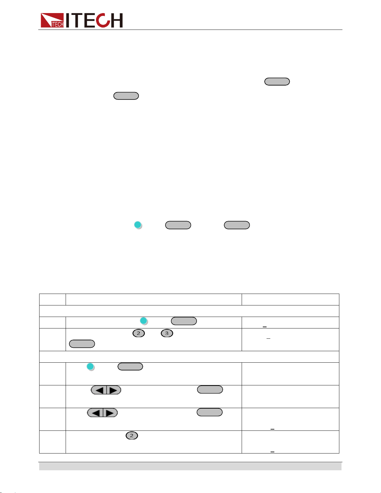
Self-test steps
Normal self-test procedures:
1. Correctly connect the power cord. Press Power key to start up.
2. After self-test, if the power supply is normal, then VFD will display the output
voltage and current status as below:
OFF
0.000V 0.0000A
0.0001V
Quick Reference
Copyright © ITECH Electronic Co., Ltd. 14
Error Information References
The following error information may occur when an error occurs during Power On
self-test:
If the EEPROM was damaged, the VFD will display: “Eeprom Failure”.
If the system parameters in EEPROM is lost, the VFD will display: “Initialize
Lost”.
If the latest operating data in EEPROM is lost, the VFD will display: “Eeprom
Reset Error”.
Exception handling
If the power supply cannot start normally, please check and take measures by
reference to steps below.
1. Check whether the power cord is correctly connected and confirm whether the
power supply is powered.
Correct wiring of power cord => 2
Incorrect wiring of power cord => Re-connect the power cord and check
whether the exception is removed.
2. Check whether the power in On. Power key is under “ ” On status.
Yes => 3
No => Please check the Power key to start power and check whether the
exception is removed.
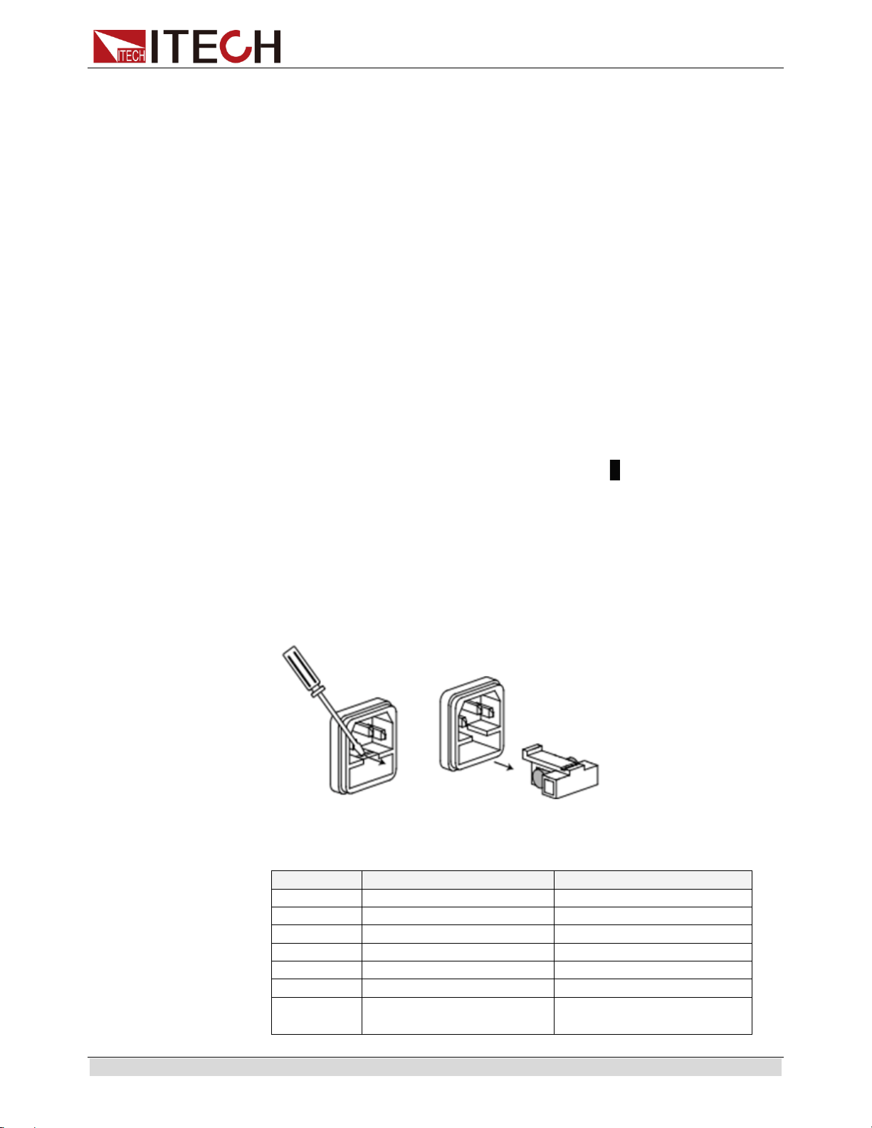
3. Check whether the fuse of power supply is burned out.
If yes, change fuse. Detailed steps:
1) Pull out power line and take out the fuse box at power line jack with a small
screw driver. As shown below.
2) If the fuse is fused, please change fuse of same specification based on
machine model. See the table blow for matching information of fuse and
machine model.
Products
Specification (110VAC)
Specification (220VAC)
IT6121B
T 5A
T2.5A
IT6122B
T 5A
T2.5A
IT6123B
T 5A
T2.5A
IT6132B
T 5A
T2.5A
IT6133B
T 5A
T2.5A
IT6162B
20AT
10AT
IT6164B
Does not support
110VAC input
15AT

Quick Reference
Copyright © ITECH Electronic Co., Ltd. 15
3) After replacement, install the fuse box back to original position, as shown
below.
NOTE
Fuse of IT6162B/IT6164B can unscrew directly by hand.

Basic operation
Copyright © ITECH Electronic Co., Ltd. 16
Chapter3 Basic operation
This chapter describes in detail how to operate the instrument manually via the
front-panel keys. This chapter is divided into the following sections:
Local and remote operation switching
Setting the Voltage
Setting the Current
On/Off Operation
Set mode and Meter mode
Save and recall operation
Trigger operation
Menu operation
OVP function
key lock function
Remote Sense and digital port functions
mΩ Meter and digital Voltage Meter
3.1 Local/Remote Mode
(Local) button can enable you switch mode from remote to local mode.
After you power on the power supply, the power supply’s default mode is local
mode, all the buttons can be used in this mode. While in remote mode, you can’t
operate through front panel directly except Local, Meter, Shift+On/Off (Lock) keys.
Local and remote mode can be controlled through PC. In addition, the mode
changing will not influence the output parameters.
3.2 Setting the Voltage
The constant voltage range is from 0V to the maximum voltage value of each
model. After pressing
V-setV-set
, the key is lit, and you can set the voltage. You
have 3 solutions to set the constant voltage value.
Solution1:
Step1: Power on the IT6100B series instrument
Step2: Press
V-setV-set
Step2: Press to move the cursor and press the and keys to
change the value
Step3: Press
Enter
to confirm.
Solution2:
Step1: Power on the IT6100B series instrument
Basic operation
Copyright © ITECH Electronic Co., Ltd. 17
Step2: Press
V-setV-set
Step3: Press to move the cursor and turn the knob to change the value
Solution3:
Step1: Power on the IT6100B series instrument
Step2: Press
V-setV-set
Step3: Use the numeric keys
0
~
9
to change the voltage value.
Step4: Press
Enter
to confirm.
3.3 Setting the Current
The constant current output range is from 0A to the maximum current value of each
model. After pressing
I-setI-set
, the key is lit, and you can set the current. It is very
easy for you to set the constant current output.
Solution1:
Step1: Power on the IT6100B series instrument
Step2: Press
I-setI-set
Step2: Press to move the cursor and press the and keys to
change the value
Step3: Press
Enter
to confirm.
Solution2:
Step1: Power on the IT6100B series instrument
Step2: Press
I-setI-set
Step3: Press to move the cursor and turn the knob to change the value
Solution3:
Step1: Power on the IT6100B series instrument
Step2: Press
I-setI-set
Step3: Use the numeric keys
0
to
9
to change the voltage value.
Step4: Press
Enter
to confirm.
3.4 On/Off Operation
On/Off
button is used to control the output state of power supply. When
On/Off
button is lit, it indicates the output is on. When output is on, the indicator
CV/CC on the VFD will be lit.
Note: make sure you have connected power supply well first, then press
On/Off
button.
Basic operation
Copyright © ITECH Electronic Co., Ltd. 18
3.5 Set mode and Meter mode
Set mode: you can set the voltage and current in this mode, and the voltage and
current displayed on the VFD is the setting value.
Meter mode: the voltage and current displayed on the VFD is the read-back value.
Set mode and meter mode can be switched by pressing
MeterMeter
key.
When
MeterMeter
key is pressed, the key is lit, it is in meter mode, when press it
again, it is set mode, the key is grey.
3.6 CC and CV
The power supply has a constant voltage/constant current automatic conversion
feature.
When in CV mode, the power supply will provide a constant voltage, with the
changes of the load, if the current increases to the current setting, then it will
convert to CC mode. The power supply will provide a constant current.
CV indicator represents it’s now in CV mode, CC indicator means it’s now in CC
mode.
3.7 Save and recall operation
You can use (Shift)+
Recall
(Save) or
Recall
or use the SCPI order *SAV,
*RCL to store up to 10×10 different output states in storage register locations.
The parameters can be saved are: 1. Voltage set 2. Current set 3. OVP set 4. The
parameters under System menu.
When recall, you should pay attention to the memory group set in the menu, details
refer to chapter 5.9.
Take the example of saving parameters to memory 23 and then recall:
Step
Operation
VFD display
Save operation
1
Press compound keys (Shift)+
Recall
(Save)
Save 1
2
Press numeric keys and , then press
Enter
to confirm
Save 23
Change the memory group in the menu
3
Press (Shift)+
I-setI-set
(Menu) to the menu
MENU
Config System Edit_List
4
Press to select “Config”, press
Enter
to
confirm.
CONFIG MENU
Initialize Memory Out_Recal
5
Press to select “Memory”,press
Enter
to
confirm
MEMORY GROUP SET
group = 0
6
Press numeric key to set the memory group to 2
MEMORY GROUP SET
group = 2
Basic operation
Copyright © ITECH Electronic Co., Ltd. 19
Recall operation
7
Press
Recall
(then the key is lit) , and then press
numeric key
3.8 Trigger operation
You need to select the trigger mode from the menu before using this function.
Details refer to TRIG item in the system menu.
If the trigger source is selected to “Manual”, after you edit a list file, press
(Shift)+
Enter
(Trigger) to give a trigger signal. During the running process
Enter
button will flash all the time.
3.9 Menu Operation
3.9.1 Menu description
Press (Shift) +
I-setI-set
(Menu) to enter menu mode. The menu parameters
will be displayed on the VFD. Use up and down keys to scroll through the menu list
and press
Enter
to select a menu and view the parameters. Press
ESC
to
return to the higher level menu and to return to the main operating mode.
MENU
Menu
Config
CONFIG MENU
Configuration menu
Initialize
Reset config?
Select whether to reset the config menu
No
Do not reset the config menu.
Yes
Reset the config menu.
Memory
Memory GROUP SET
Memory group set for save/recall
function
group=0 (0 - 9)
Out_Recal
OUT RECALL
Set the Power ON/OFF state after
power up.
On
“Remembers” and restores the Power
ON/OFF state of the power supply
before power was turned off
Off(default)
Disable this function.
Set_Recall
SET RECALL
Recall operating parameters of power
supply after power up
On(default)
“Remembers” and restores the
operating parameters of the power
supply (voltage, current settings..)
before power was turned off.
Off
Disable this function. The parameters
are the default set when power up.
Buzzer
KEY BUZZER
Keypad sound setting
On
Enable key sound
Off(default)
Disable key sound
Knob
KNOB LOCK
Enable/disable the rotary knob.
Basic operation
Copyright © ITECH Electronic Co., Ltd. 20
On
Lock the rotary knob
Off(default)
Unlock the rotary knob
Comm
COMMUNICATION
Communication port select
RS232(def)
RS232
USBTMC
USB
GPIB
GPIB
Port
PORT FUNCTION
Select mode of digital port
Trigger
Trigger mode
RI/DFI
Power switch control and discrete fault
indication
Digital
Data port
Trig
TRIGGER SOURCE
Trigger source select
Manual
Trigger by keys on the front panel
External
Ext. Trigger signal is applied to the
digital port in the rear panel.
Bus
Remote command trigger mode.
Immediat
Trigger by TRIG:IMM command
RI
RI MODE
Config RI (Remote Inhibit) mode
Off
Disable this function
Latching
At the falling edge of the TTL level, the
output turns on.
Live
The output is on at high level and turned
off at low level.
DFI
DFI SOURCE
Config DFI (Discrete Fault Indicator)
mode
Off
Disable this function
QUES
Question bit
OPER
Operation bit
ESB
Event State bit
RQS
Require bit
System
SYSTEM MENU
System menu
Limit_volt
LIMIT VOLTAGE SET
Limit voltage setting
Limit=30.10V
On_Timer
ON TIMER STATE
Output timer function state
On
ON TIMER SET
timer = 60.000(0.01 - 60000.0S)
Off(default)
Turn off the output timer.
DVM
DVM RANGE
Digital multimeter range setting
Auto
Auto range
Low
Low range
High
High range
OutMode
OUTPUT MODE…
Set Output Mode
Volt-Wave Prio
Voltage output priority
Curr-Wave Prio
Current output priority
Range
RANGE MENU
Set Output Range
Low_Range
Low range
High_Range
High range

Basic operation
Copyright © ITECH Electronic Co., Ltd. 21
Edit_List
RECALL LIST
FILE
Recall the existing list file.
Recall 1
NOTE
Only IT6162B/IT6164B Power contain OutMode function.
3.9.2 Menu function
Memory group (Memory)
Power supply can save some often-used parameters in a nonvolatile memory
(capacity is 10*10 groups). This function can make the operations more convenient.
Customer can save and recall parameters quickly.
GRP0: This indicates saving power supply parameters in memory location 0-9.
GRP1: This indicates saving the parameters in memory location 10-19.
GRP2-GRP9 by parity of reasoning.
Output Recall (Out_Recall)
This function can help you set the output state when the power supply is powered
on. If you select On, the power supply will keep the state of last time as it is turned
off. If you select Off, this function is disabled. Default is On.
Set_Recall
This item can set power on state of parameters. If you select OFF item, then all the
parameters will be initialized to the factory setting. Output voltage and current will
always be 1V/0.1A.Otherwise the output value will be the same with last power off
state. The default setting is ON.
Key sound set (Buzzer)
This item can set the key sound state. If in ON mode, then when you press a button,
the power supply will beep. If in OFF mode, the beeper will not make a sound. The
default set is in OFF mode.
Rotary knob set (KNOB)
This item is used to set rotary knob lock state. In OFF mode, you can use this
rotary knob to set the output value and overturn the menu items. If knob lock is in
ON mode, the knob can’t be used. The default setting is in OFF mode.
Communication (COMM)
IT6100B power supply support three standard communication interfaces:
RS232/USB/GPIB. In this option, you can select the communication interface
according to your demands.
The range of GPIB address is 0-30.
Baudrate can be chosen when communicate with RS232---4800, 9600, 19200,
38400, 57600, 115.2K. Data bit is 8, Check digit have three choices:
NONE,ODD,EVEN.
Basic operation
Copyright © ITECH Electronic Co., Ltd. 22
Before you begin to carry out communication, please make sure the configure in
our unit agrees with PC configure. More information please refer to chapter 6.
PORT mode
A 4-pin connector in the rear panel is provided for digital input and output signals.
This digital port can be configured to provide Fault/Inhibit, External Trigger or
Digital I/O functions. The signal level is TTL.
Choose one mode in the menu:
Trigger: select the port mode as trigger, In(+) function as TRIG pin, In(-) function
as GND
RI/DFI: The Inhibit Input pin can be used to control the output state of the power
supply (RI function). The Fault Output pin (DFI function) can be used to indicate
internal faults of the power supply.
Digital: Digit I/O port, Read and control output and input state of the 2 available
pins.
The default set is Trigger.
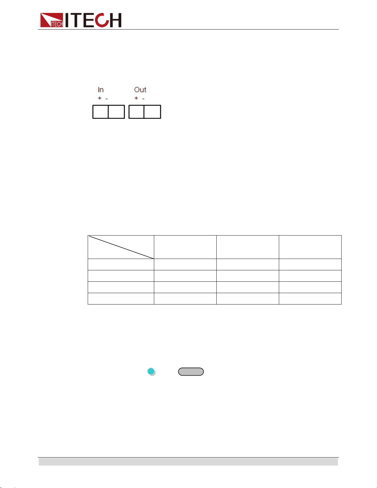
Mode
Pin
Trigger
RI/DFI
Digital I/O
In +
Trigger in
Inhibit Input
Digital Input
In -
GND
GND
GND
Out +
No Use
Fault Output
Digital Output
Out -
No Use
GND
GND
Trigger source (TRIG)
The power supply supports 4 different trigger modes for LIST test. Manual,
External, Bus and Immediat. Configure one of the trigger sources before
performing trigger operation:
Manual: When this function is enabled, you can generate an immediate trigger
pulse by pressing (Shift)+
Enter
(Trigger)
External: External trigger signal (TTL), you should set PORT as Trigger in the
menu at the same time. When this function is enabled, the power supply can be
triggered with a low TTL pulse applied to pin In + and In – (short In + and In –) of
the terminal connector in the rear. The TTL on pulse width should be at least 5 ms.
Bus: When this function is enabled, you can trigger the power supply by sending a
TRIgger command to the power supply
Immediat: You can trigger the power supply by sending the command TRIG: IMM
in any case, regardless of the trigger source selected in the current menu.
Basic operation
Copyright © ITECH Electronic Co., Ltd. 23
The default set is Manual
Remote Inhibit (RI)
Used to turn off the output of the power supply. Can be used to turn off several
power supplies simultaneously.
The input terminals are In + and In -
The RI input has 3 modes: LATCHING, LIVE and OFF
OFF: The signal applied to the RI port does not affect the output state of the power
supply.
Latching: When In + and In – are shorted, the output will be OFF, the VFD
displays “RI” at the same time; When disconnect In + and In –, the output will
remain OFF.
Live: When In + and In – are shorted, the voltage will change to 0V, (check in
METER mode and ON state), the VFD displays “RI” at the same time; When
disconnect In + and In –, the power supply will output as the voltage setting. “RI” on
the VFD will disappear.
Note: when use RI function, the PORT item in menu should be selected to
RI/DFI.
Discrete Fault Indicator (DFI)
The output level of DFI (Out + and Out –) reflects the state of the register bit.
The DFI function can be activated by state changes of the QUES, OPER, ESB,
RQS bits
Off: The output level of the DFI port remains high.
QUES: The output level of DFI reflects the state of the QUES bit. When the QUES
bit is 1, the DFI output goes to a high level.
OPER: The output level of DFI reflects the state of the OPER bit.
ESB: The output level of DFI reflects the state of the ESB bit.
RQS: The output level of DFI reflects the state of the RQS bit.
When use DFI function, the PORT item in the menu should set to RI/DFI.
The operation:
1. Press (Shift) +
I-setI-set
(Menu) to menu, press to select Config,
press
Enter
to confirm.
2. Press to select Port, press
Enter
to confirm.
3. VFD display Trigger RI/DFI Digital, Press to select RI/DFI,
press
Enter
to confirm.
4. VFD return to Comm Port Trig RI DFI, press to select DFI,
press
Enter
to confirm.
5. Select DFI source, e.g., OPER, then press
Enter
to confirm.
Basic operation
Copyright © ITECH Electronic Co., Ltd. 24
When the value in operation register changes, the TTL level of Out + and Out –
will change simultaneously.
The default set of config menu
Memory
group 0
Out_Recal
Off
Set_Recall
On
Buzzer
Off
Knob
Off
Comm
RS232
Port
Trigger
Trig
Mauual
RI
Off
DFI
Off
Limit voltage (Limit_Volt)
Limit voltage range is 0V - Vmax.
Limit voltage is used to limit the voltage setting for a certain device under test.
For example: the limit voltage is set to 12V, when you set voltage to 15V (over 12V),
then the voltage will auto adjust to 12V.
The operation to set voltage limit:
1. Press (Shift) +
I-setI-set
(Menu) to menu
2. Press to System menu, press
Enter
to confirm
3. Select Limit_Volt in System menu, Press
Enter
to set the voltage limit
The default set of Limit_volt is the max rated voltage.
ON TIMER STATE
This item is used to set the “time on- load” function. In ON mode, the indicator light
“Timer” will be lit on the VFD screen. When output of power supply is enabled,
timer will begin to work, after reaching the definite time, output will be off
automatically. If in OFF mode, the timer function will not be enabled. The default
set is OFF.
RESET
This item is used to reset all items in the menu. If you select >YES, then unit will
restored to factory setting. If you select >NO, all setting in the menu will remain
unchanged.
OutMode (IT6162B/IT6164B Specific function)
This item is used to set the power supply output mode, including Volt-Wave Prio
(voltage priority) mode and Curr-Wave Prio (current priority) mode. Under voltage
mode, when output wave quality is maintained, current may overshoot; under
current mode, when current output wave quality is maintained, voltage rise speed
will get slower.
Basic operation
Copyright © ITECH Electronic Co., Ltd. 25
Voltage Range (IT6164B Specific function)
IT6164B is a double-range output power supply. This item is used to set the
voltage/current output range: High and Low. As shown below.
Model
Voltage Range
Output range
IT6164B
High
Voltage output range: 0V ~ 60V
Current output range: 0A ~ 20A
Low
Voltage output range: 0V ~ 30V
Current output range: 0A ~ 40A
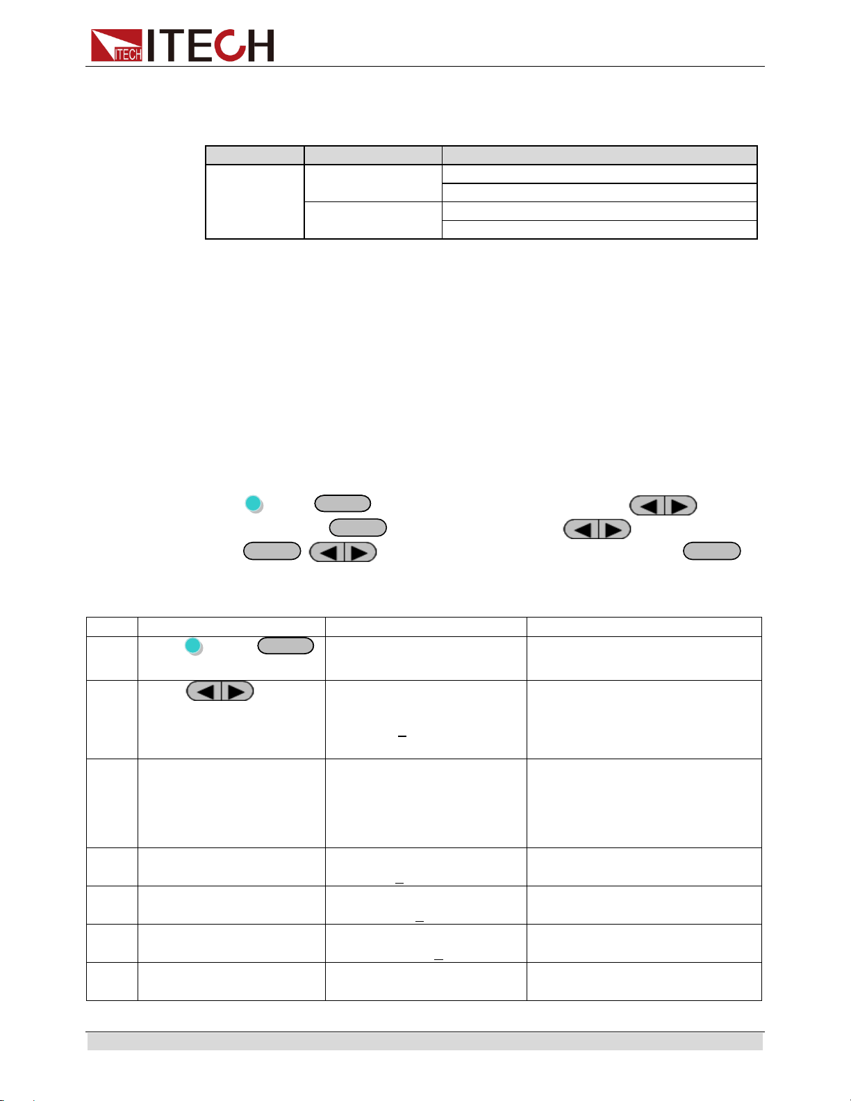
List Set
This mode allows you to create a sequence of steps, store it into the power
supply’s nonvolatile memory and execute it.
The input parameters for generating a list include the name of the list file, the input
steps (no more than 999 steps), the step time (the minimum is 1 mS) and the value
of each step.
After you finish the editing process and enable LIST mode, if you receive a trigger
signal, power supply will begin to work according to the sequence steps you’ve
edited.
Choose a trigger source in the menu, take MANUAL for example:
Press (Shift)+
I-setI-set
(Menu) to system menu, and press to select
Config, press
Enter
to confirm. Press to select Trig,
press
Enter
, to select trigger source as Manual, press
Enter
to
confirm.
The operation to edit a LIST with 2 steps:
Step
Operation
VFD display
Description
1
Press (Shift)+
I-setI-set
(Menu) to menu
MENU
Config System Edit_List
2
Press to
select Edit_List, press
Enter to confirm, and
then set the LIST name
RECALL LIST FILE
Recall 5
Recall LIST file, when recall a
List file already saved, press
Esc in the next step.
3
Set the run mode of
LIST, select Continuous
LIST MODE
Continuous Step
Continuous: LIST will run
continuously; step: another
trigger signal should be sent
when run a new step.
Here, take Step as example.
4
Set the list repeat count
LIST COUNT SET
Repeat= 2
Repeat count range:1~65535
5
Set List step count
LIST STEP SET
Total Step= 3
Total step range:2~999 (1 can
be set, but it makes no sense)
6
Set the voltage for the
1th step
LIST VOLTAGE SET
step001=12.000V
Voltage range: 0~Vmax
7
Set the current for the 1th
step
LIST CURRENT SET
step001=1.0000A
Current range: 0~Imax
Basic operation
Copyright © ITECH Electronic Co., Ltd. 26
8
Set the time width for the
1th step
LIST WIDTH SET
step001=2.000S
Time range: 0.001~3600S, if
LIST mode in step 3 is set as
Step, then no time width can be
set.
9
Set the voltage for the
2nd step
LIST VOLTAGE SET
step002=8.000V
Voltage range: 0~Vmax
10
Set the current for the
2nd step
LIST CURRENT SET
step002=1.0000A
Current range: 0~Imax
11
Set the time width for the
2nd step
LIST WIDTH SET
step002=2.000S
Time range: 0.001~3600S, if
LIST mode in step 3 is set as
Step, then no time width can be
set.
12
Save List file
SAVE LIST FILE
Save 5
Range: 1~7
Run LIST:
Take step mode and trigger source as manual for example.
Step
Operation
VFD display
Description
1
Press (Shift)+ (List) to
select the LIST to be run.
Run List 5
-
2
Press Enter to confirm.
L5: EE
Enter key is lit
3
Press (Shift) +
EnterEnter
(Trigger) to trigger
L5:00001:01
The 1st step of the first count
4
Press (Shift) +
EnterEnter
(Trigger) to trigger
L5:00001:02
The 2nd step of the first
count
5
Press (Shift) +
EnterEnter
(Trigger) to trigger
L5:00002:01
The 1st step of the second
count
6
Press (Shift) +
EnterEnter
(Trigger) to trigger
L5:00002:02
The 2nd step of the second
count
7
Press (Shift) +
EnterEnter
(Trigger) to trigger
L5: EE
The selected List file runs to
the end.
Press Esc to escape the List in any case.
Basic operation
Copyright © ITECH Electronic Co., Ltd. 27
TriggerTrigger
NOTE
In editing LIST, IT6164B has more modes for selection. Press to select
Edit_List, and press Enter to confirm. The panel displays: Speed Prio (high speed mode) and
Power prio (normal mode). Under normal mode, time range is set from 500mS. For mode
switch, follow normal process. Under high speed mode, time range is set from 10mS with step
of 1mS. The mode is maintained at high range, and if triggered, voltage will be directly output.
3.10 OVP
IT6100B series power supply provide OVP function, press (Shift) +
V-setV-set
(OVP) button can enable you to set the over voltage protection value,
when it’s enabled, “Prot” will display on the VFD.
Over voltage may be caused by internal defect or customer’s incorrect operation
(such as output voltage rising), or external voltage too high. Once power supply is
protected (OVP), the output will be off immediately and “OVP” indicator light will be
lit, the instrument will issue 3 beep( regardless of the buzzer set in the menu).
Avoid external voltage that across the output terminals exceeding the 120% of
rated voltage or it will damage out power supply!
When power supply in OVP state, please check the external factors first, after you
exclude the external factors, press ON/OFF button to enable output again. If in
communication state originally, you should send command OUTP ON to enable
output.
3.11 Key Lock
Key lock function can prevent any incorrect touching on the keypad.
Press (Shift)+
On/Off
(Lock) button to set the key lock state. If keyboard has
been locked, the indicator light * will display on the VFD .In addition, when key
board are lock, all buttons can’t be used but
On/Off
,
MeterMeter
, (Shift).Press
(Shift)+
On/Off
(Lock) once again will relieve key lock function.
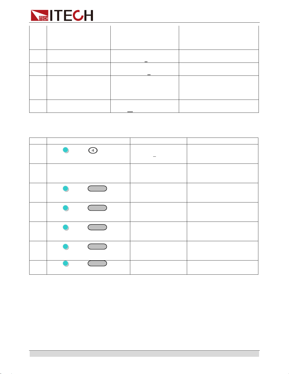
3.12 Terminals at rear panel
The terminals at rear panel of IT6100B include: remote sense, DVM and milliohm
meter, I/O port.
The terminals at rear panel of IT6121B/IT6122B/IT6123B/IT6132B/IT6133B.
Basic operation
Copyright © ITECH Electronic Co., Ltd. 28
The terminals at rear panel of IT6160B.
3.12.1 Remote sense
Remote voltage sensing is used to maintain good regulation at the load and reduce
the degradation of regulation that would occur due to the voltage drop in the leads
between the power supply and the load. By connecting the supply for remote
voltage sensing, voltage is sensed at the load rather than at the supply's output
terminals. This will allow the supply to automatically compensate for the voltage
drop in the load leads and improve regulation.
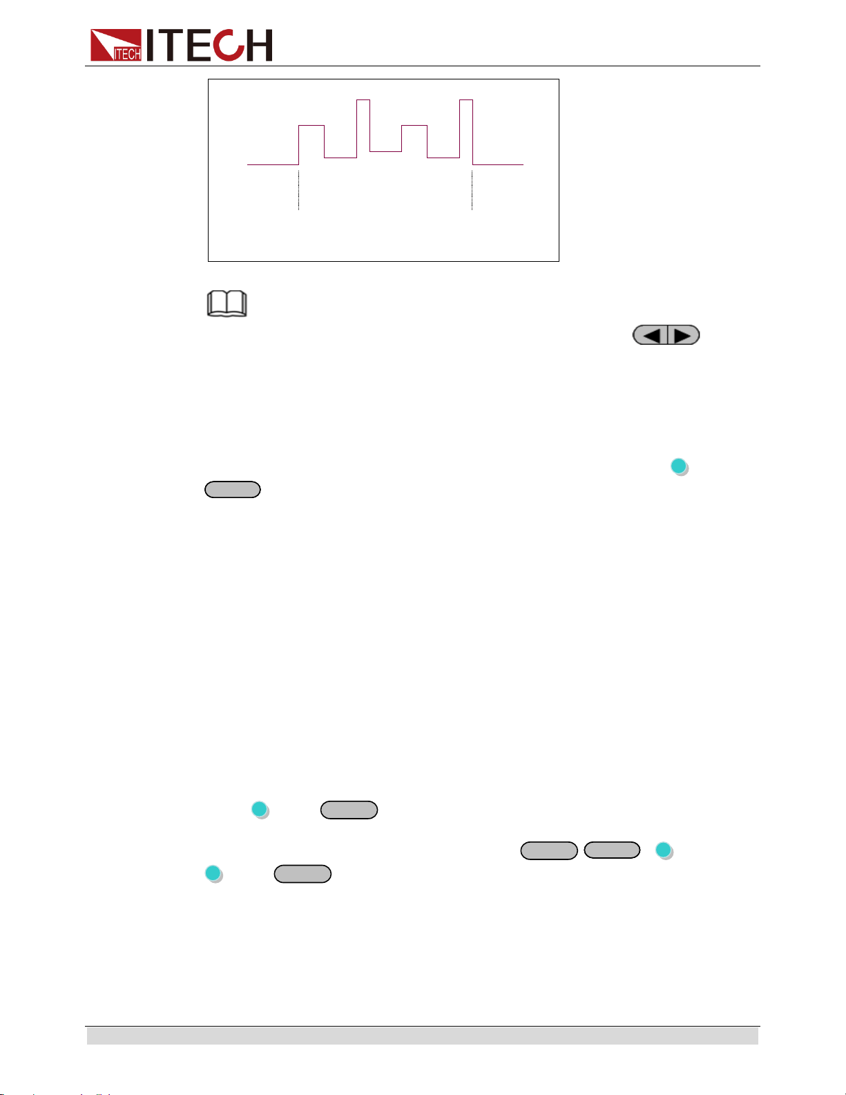
Local sense
Local sense doesn’t compensate for the voltage drop on the wire, the operation is:
1. Use the shorting clip already installed on the rear panel, or install wires
between Drive+ and Sense+, Drive- and Sense-.
2. Connect the positive and negative terminals on the front panel or the Drive +
Drive- terminals on the rear panel to the device under test (DUT).
Wiring Schematic Diagram of Local Measurement of
IT6121B/IT6122B/IT6123B/IT6132B/IT6133B is as follows:
Wiring Schematic Diagram of Local Measurement of IT6162B/IT6164B is as
follows:
Basic operation
Copyright © ITECH Electronic Co., Ltd. 29
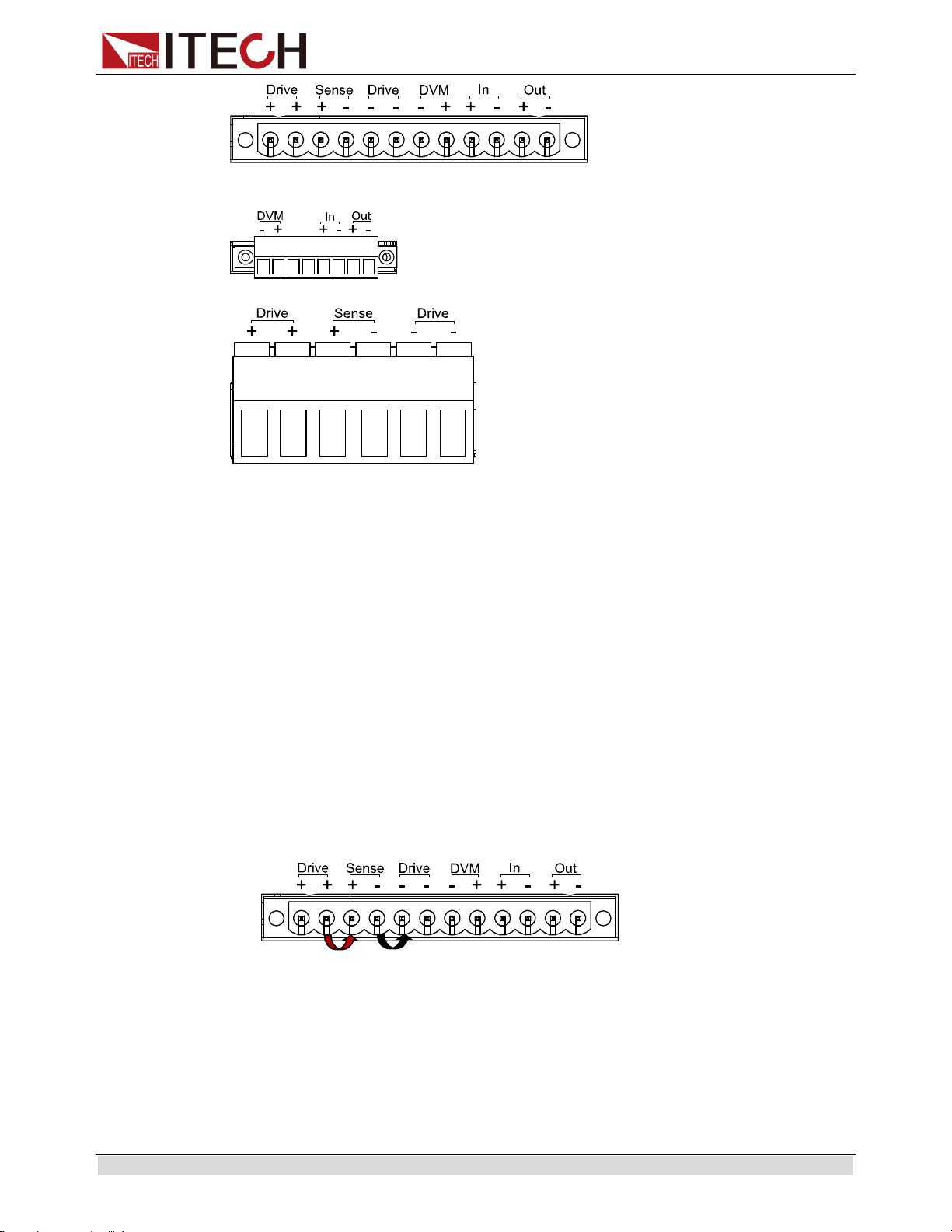
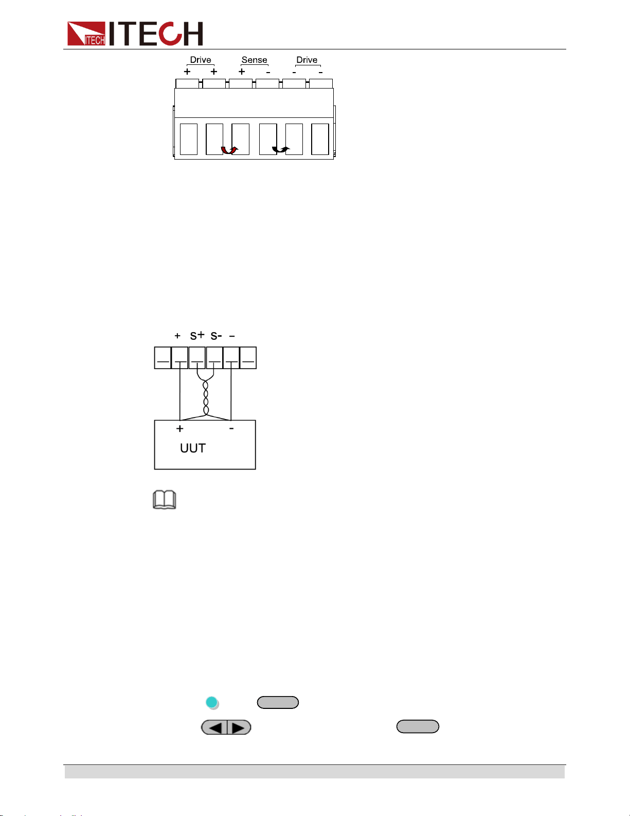
Remote sense
Remote sense can compensate for the voltage drop on the wire, the operation is:
1. Uninstall the wire or shorting clip between the Drive+ and Sense+, Drive- and
Sense-
2. Connect a couple of wires from Sense+, Sense- and the device under test
3. Connect wires from positive and negative terminals on the front panel or the
Drive+ and Drive- terminal to DUT
Wiring Schematic Diagram of Remote Measurement is as follows:
NOTE
In order to ensure the stability of the system, please install armored twisted pair cable from
Sense+ , Sense- and the device under test.
3.12.2 Digital Volt Meter (DVM) and Milliohm Meter
The power supply provides a built-in 5 1/2 Digital Volt meter and milliohm meter.
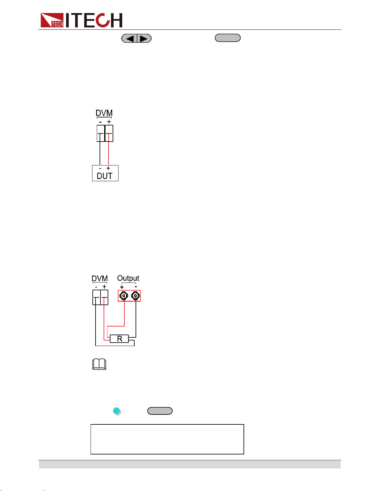
Digital Volt Meter (DVM)
Digital Voltage Meter can be used to measure external DC voltage, the range is:
0~40V. IT6162B/IT6164B measurement range is: -40V~40V.
The connectors are in the rear panel. The voltage value is displayed on the bottom
left field of the display.
The operation to adjust the voltage meter range is:
1. Press (Shift)+
I-setI-set
(Menu) to menu
2. Press to enter System menu, press
Enter
to confirm
Basic operation
Copyright © ITECH Electronic Co., Ltd. 30
3. Press to select DVM, press
Enter
to confirm
4. VFD display “Auto Low High”, indicating the range
Auto: auto range, when voltage is below 18V, the resolution is 0.1mV; when
voltage is over 18V, the resolution is 1mV
Low and High is low or high range, when in low range, the voltage resolution is
0.1mV; when in high range, the voltage resolution is 1mV
To measure voltages, connect the leads as shown here:
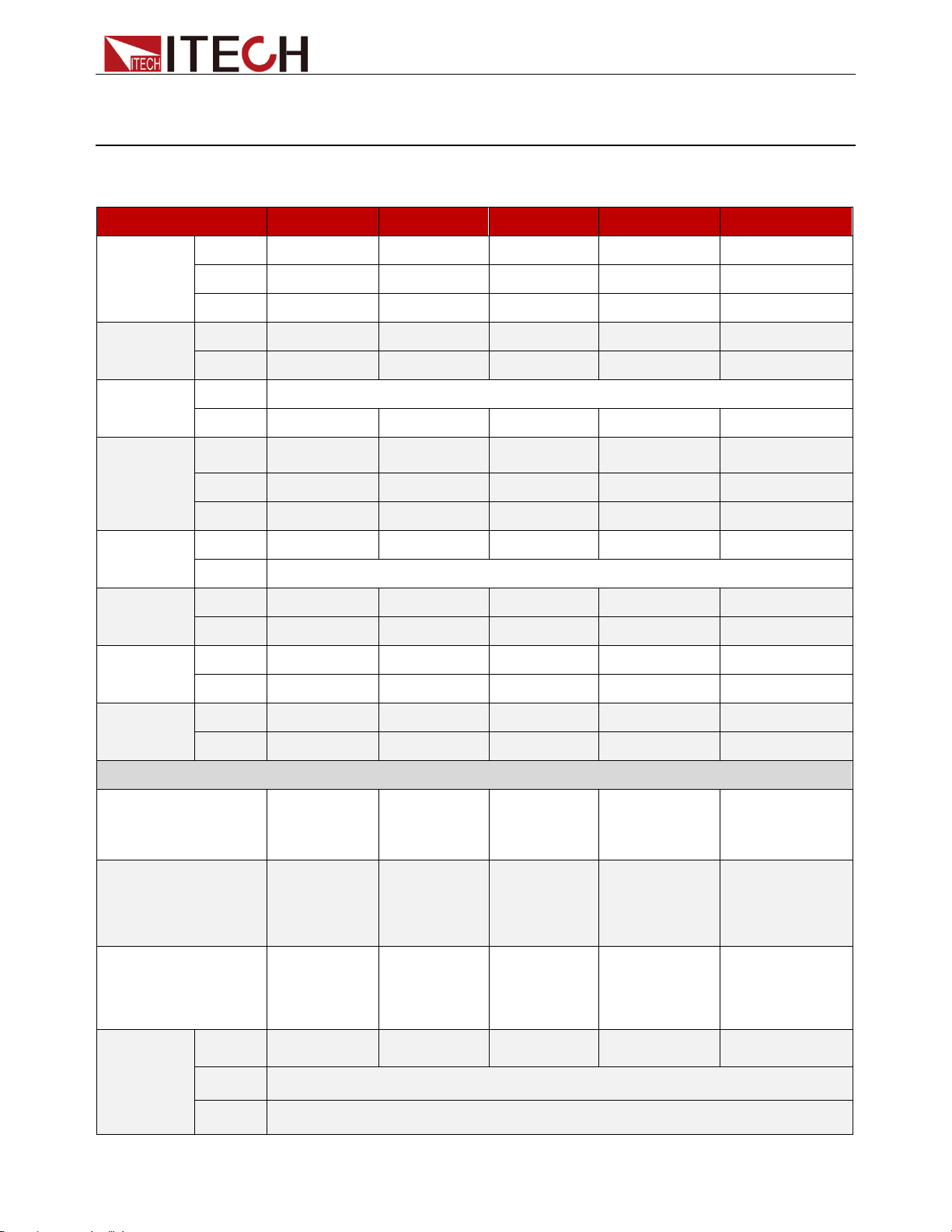
Milliohm Meter
The instrument is also equipped with a Milliohm Meter which can accurately
measure resistance up to 1kΩ.
To protect the resistor, make sure to select an appropriate power range before
connecting it to the power supply.
The range for the milliohm meter can be selected are: 0.1W, 1W, 10W.
To measure resistance, connect the resistor as shown below:
NOTE
The wires at the positive and negative terminal of the DVM should be connected at the root of
the resistance to be measured!
Switching operation of DVM and milliohm meter
Press (Shift)+
MeterMeter
(DVM/DRM)
OFF
0.0000V 0.00000A
0.000Ω Range: 10W

Basic operation
Copyright © ITECH Electronic Co., Ltd. 31
Operation to adjust milliohm meter range
When in milliohm meter mode, press (Shift) + can set the range to 0.1W
Press (Shift) + set the range to 1W
Press (Shift) +
3
set the range to 10W
3.13 Power information
The information include: Model, program version, serial number (SN).
Operation to check:
Press (Shift) + (Info) to check model and program version, and to
check SN.
IT6100B User’s Manual
Chapter4 Specification
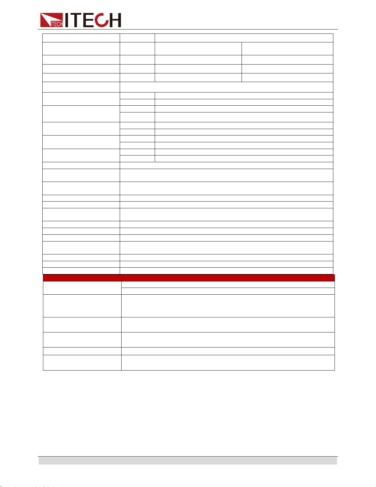
4.1 Specification
Parameter
IT6121B
IT6122B
IT6123B
IT6132B
IT6133B
Output
Ratings
voltage
0-20V
0-32V
0-72V
0-30V
0-60V
current
0-5A
0-3A
0-1.2A
0-5A
0-2.5A
power
100W
96W
86.4W
150W
150W
Line
regulation
voltage
<0.01%+1mV
<0.01%+1mV
<0.01%+1mV
<0.01%+1mV
<0.01%+2mV
current
<0.05%+1mA
<0.05%+1mA
<0.05%+1mA
<0.05%+1mA
<0.05%+0.05mA
Load
regulation
voltage
<0.01%+2mV
current
<0.05%+0.1mA
<0.05%+0.1mA
<0.05%+0.1mA
<0.05%+1.5mA
<0.05%+0.5mA
Ripple&Noise
(20HZ-7MHZ)
voltage
<1mv Vrms
<1mv Vrms
<1mv Vrms
<1mv Vrms
<1mv Vrms
<3mv Vpp
<3mv Vpp
<4mv Vpp
<4mv Vpp
<5mv Vpp
current
<3mA rms
<3mA rms
<3mA rms
<4mA rms
<3mA rms
Setup
resolution
volage
1mV
1mV
1mV
1mV
1mV
current
0.1mA
Setup
accuracy
Voltage
±0.03%+3mV
±0.03%+3mV
±0.03%+6mV
±0.03%+3mV
±0.03%+6mV
Current
±0.05%+2mA
±0.05%+2mA
±0.05%+1mA
±0.05%+2.5mA
±0.05%+1.5mA
Readback
resolution
Voltage
0.1mV
0.1mV
0.1mV
0.1mV
0.1mV
current
0.01mA
0.01mA
0.01mA
0.01mA
0.01mA
Readback
accuracy
Voltage
±0.02%+3mV
±0.02%+3mV
±0.02%+5mV
±0.02%+3mV
±0.02%+5mV
Current
±0.05%+2mA
±0.05%+2mA
±0.05%+1mA
±0.05%+2.5mA
±0.05%+1.5mA
Response time
Response time
<200uS
<200uS
<200uS
<200uS
<200uS
Rising time
(From 10%-90%FS)
<20mS
<20mS
<20mS
<20mS
<20mS
Falling time
(From 90%-10%FS)
<200mS
<150mS
<150mS
<250mS
<200mS
OVP
Range
1-19V
1-31V
1-71V
1-29V
1-59V
accuracy
±(setting value*0.5%+0.5V)
Response
time
<10mS
Specification
Copyright © ITECH Electronic Co., Ltd. 33
DVM(DC)
Readback accuracy
±0.02%+10mV
Readback resolution
0.1mV(<10V) ; 1mV(>10V)
Difference-mode voltage
0-40Vpk
Common-mode voltage
0-30Vpk
Common-mode rejection
ratio
<0.1%
Weight(net)
7Kg
Parameter
IT6162B
Rated value
( 0 °C -40 °C )
Voltage
0-20V
Current
0-50A
Power
1000W
Load regulation
(%of Output+Offset)
Voltage
≤0.01%+10mV
Current
≤0.1%+10mA
Line regulation
(%of Output+Offset)
Voltage
≤0.02%+2mV
Current
≤0.1%+2mA
Setup resolution
Voltage
1mV
Current
1mA
Readback resoultion
Voltage
1mV
Current
1mA
Setup accuracy
(Within twelve months
25°C ±5 °C )
(%of Output+Offset)
Voltage
≤0.02%+2mV
Current
≤0.1%+25mA
Readback accuracy
(Within twelve months
25°C ±5 °C )
(%of Output+Offset)
Voltage
≤0.02%+2mV
Current
≤0.05%+15mA
Ripple
(20Hz -20MHz)
Voltage
≤ 4mVp-p / 1.2 mV rms
Current
≤15mArms
Tem coefficient
(%of Output/°C +Offset)
Voltage
0.01%+2mV
Current
0.01%+20mA
Readback Tem coefficient
(%of Output/°C +Offset)
Voltage
0.01%+2mV
Current
0.01%+15mA
Rising Time at no load
Voltage
≤1mS
Rising time at full load
Voltage
≤1mS
Falling time at no load
Voltage
≤50mS
Falling time at full load
Voltage
≤1mS
Dynamic response time
≤200uS
AC input
Voltage1
110V±10%
Voltage2
120V±10%
Voltage3
220V±10%
Voltage4
230V±10%
Frequency
47HZ-63HZ
Setup stability -30min
(%of Output +Offset)
Voltage
0.01%+2mV
Current
0.1%+20mA
Setup stability -8h
(%of Output +Offset)
Voltage
0.015%+2mV
Current
0.15%+20mA
Readback stability-30min
(%of Output +Offset)
Voltage
0.01%+2mV
Current
0.1%+20mA
Readback stability -8h
(%of Output +Offset)
Voltage
0.015%+2mV
Current
0.15%+20mA
Fuse specification
10A (Voltage3, 4) / 20A (Voltage1, 2)
Specification
Copyright © ITECH Electronic Co., Ltd. 34
Remote sense
compensation
1V
Programming response
time
20mS (AVG)
Power factor
0.7Max
Maximum input current
20A
Maximum input apparent
power
2400VA
Storage temperature
-10°C~70°C
Protect function
OVP/OCP/OTP
Communication Interface
GPIB/USB/RS232
Withstand voltage(output
to the ground)
200V
Operating temperature
0~40°C
Dimension (mm)
483mmW*88.4mmH*664.1mmD
Weight (Kg)
30Kg
DVM
Display accuracy
Low Range (0 ~±5.5V) ≤±1.5mV
High Range (0 ~±40V) ≤0.02%±3mV
Display
Temp.coefficient
(% of Intput/°C +Offset
0.02%+2 mV
Display stability -30min
(% of Output +Offset)
0.02%+2 mV
Display stability -8 h
(% of Output +Offset)
0.02%+2.5 mV
Measurement range
-40V - +40V
Input Common-mode
voltage
< 200Vdc
Parameter
IT6164B
Rated value
( 0 °C -40 °C )
Voltage
0-30V
0-60V
Current
0-40A
0-20A
Power
1200W
Load regulation
(%of Output+Offset)
Voltage
≤0.01%+10mV
Current
≤0.1%+10mA
Line regulation
(%of Output+Offset)
Voltage
≤0.02%+2mV
Current
≤0.1%+2mA
Setup resolution
Voltage
1mV
Current
1mA
Readback resoultion
Voltage
1mV
Current
1mA
Setup accuracy
(Within twelve months
25°C ±5 °C )
(%of Output+Offset)
Voltage
≤0.02%+6mV
Current
≤0.1%+15mA
Readback accuracy
(Within twelve months
25°C ±5 °C )
(%of Output+Offset)
Voltage
≤0.02%+6mV
Current
≤0.05%+15mA
Ripple
(20Hz -20MHz)
Voltage
≤ 5mVp-p / 1.2 mV rms
Current
≤15mArms
Tem coefficient
(%of Output/°C +Offset)
Voltage
0.01%+2mV
Current
0.01%+20mA
Readback Tem coefficient
Voltage
0.01%+2mV
Specification
Copyright © ITECH Electronic Co., Ltd. 35
DVM
Display accuracy
Low Range (0 ~±5.5V) ≤±1.5mV
High Range (0 ~±40V) ≤0.02%±3mV
Display
Temp.coefficient
(% of Intput/°C +Offset)
0.02%+2 mV
Display stability -30min
(% of Output +Offset)
0.02%+2 mV
Display stability -8 h
(% of Output +Offset)
0.02%+2.5 mV
Measurement range
-40V - +40V
Input Common-mode
voltage
< 200Vdc
(*1) Indicates the interval at which the output waveform changes by 10% to 90%.
(*2) Indicates the interval at which the load changes 50-100% and the output
voltage recovers to within 75 mV of the set value.
*The above specifications may be subject to change without prior notice.
(%of Output/°C +Offset)
Current
0.01%+15mA
Rising Time at no load
Voltage
≤ 1mS ¹
≤2 mS ¹
Rising time at full load
Voltage
≤ 1mS ¹
≤2 mS ¹
Falling time at no load
Voltage
≤50 mS ¹
≤120 mS ¹
Falling time at full load
Voltage
≤1 mS ¹
≤2 mS ¹
Dynamic response time
≤200 uS
2
AC input
Voltage
220V±10%
Frequency
47HZ-63HZ
Setup stability -30min
(%of Output +Offset)
Voltage
0.01%+2mV
Current
0.1%+20mA
Setup stability -8h
(%of Output +Offset)
Voltage
0.015%+2mV
Current
0.15%+20mA
Readback stability-30min
(%of Output +Offset)
Voltage
0.01%+2mV
Current
0.1%+20mA
Readback stability -8h
(%of Output +Offset)
Voltage
0.015%+2mV
Current
0.15%+20mA
Fuse specification
T 15A
Remote sense
compensation
1V
Programming response
time
20mS (AVG)
Power factor
0.7Max
Maximum input current
15A
Maximum input apparent
power
3000VA
Storage temperature
-10°C ~70°C
Protect function
OVP/OCP/OTP
Communication Interface
GPIB/USB/RS232
Withstand voltage(output
to the ground)
200Vdc
Operating temperature
0~40°C
Dimension (mm)
483mmW*88.4mmH*664.1mmD
Weight (Kg)
30Kg
Remote Operation Mode
Copyright © ITECH Electronic Co., Ltd. 36
Chapter5 Remote Operation Mode
IT6100B configure with three type of communication interface RS232, USB and
GPIB for user adopting any of it flexible.
5.1 RS232 interface
There is a DB9 connector at the rear of the power supply, when connect to
computer, you need to connect a cable with COM port on both side; active
connection, you need to set the front panel composite press (Shift)+
I-setI-set
key
configuration settings the same as computer configuration settings. RS-232
interface can be used to program all of the SCPI orders.
NOTE
RS232 settings must match the settings in front panel system information. If any change,
please press (Shift) +
I-setI-set
key.
RS-232 data format
RS-232 data is a 10-bit word which has a start bit and a stop bit. The start bit and
stop bit can not be edited. However, you can select the parity items with (Shift)
+
I-setI-set
key on the front panel.
Parity options are stored in nonvolatile memory.
Baud Rate
The front panel (Shift) +
I-setI-set
button allow the user to select a baud rate
which is stored in the non-volatile memory: 4800/9600/19200/
38400/57600/115200
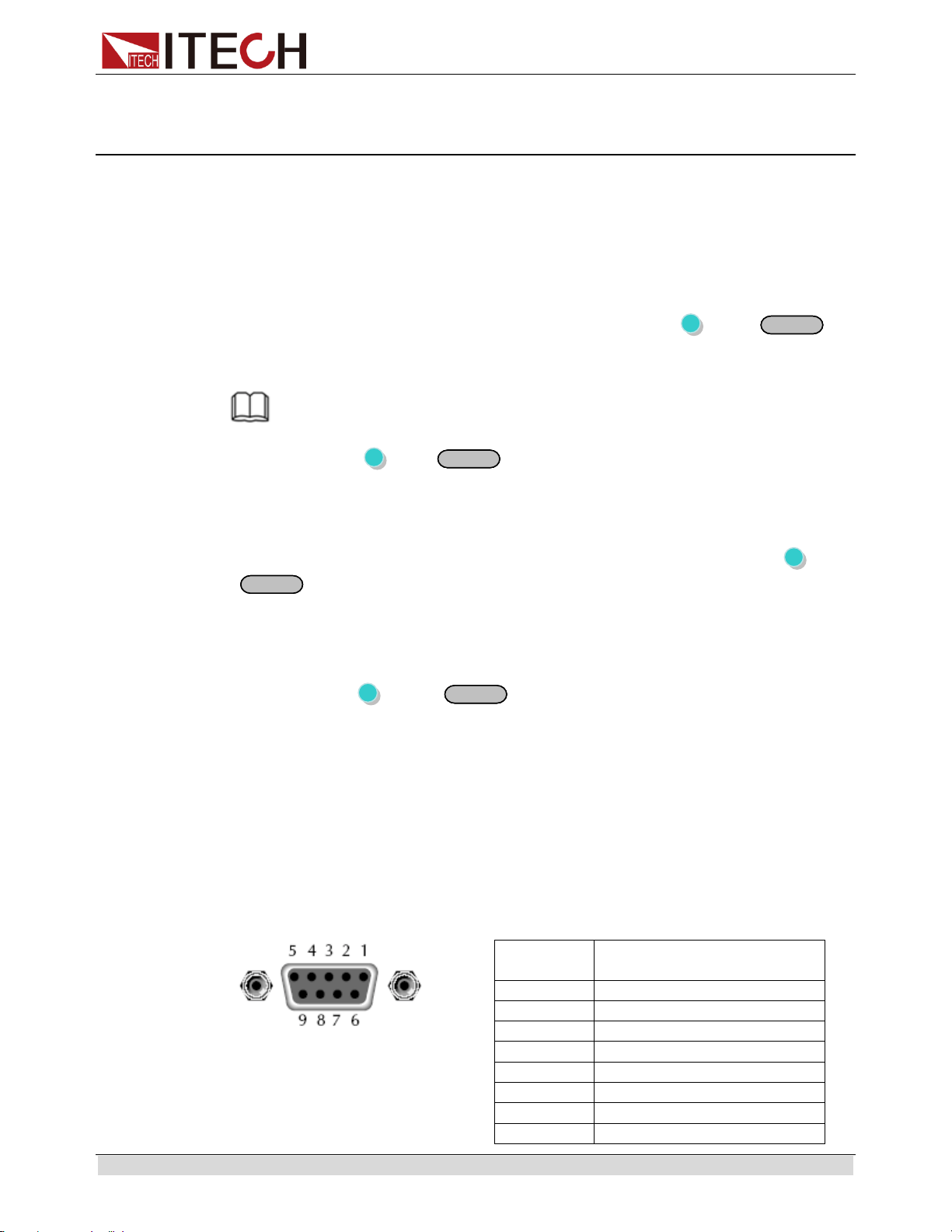
RS-232 connection cable
Use a RS232 cable with DB-9 interface, RS-232 serial port can connect with the
controller (eg PC). Do not use blank Modem cable. Below table shows the plug
pins.
If your computer is using a RS-232 interface with DB-25 connector, you need a
adapter cable with a DB-25 connector at one end and the other side is a DB-9(not
blank modem cable)
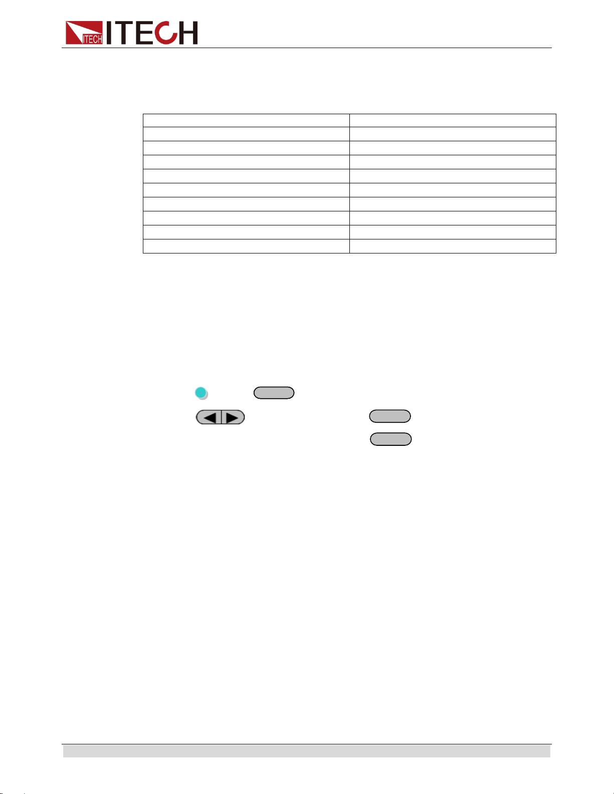
RS232 Pins of Plug
Base pin
number
Description
1
No conjunction
2
TXD, data transmission
3
RXD, data receiving
4
No conjunction
5
GND, grounding
6
No conjunction
7
CTS, clear to send
8
RTS, request to send

Remote Operation Mode
Copyright © ITECH Electronic Co., Ltd. 37
9
No conjunction
RS-232 Troubleshooting:
If there is RS-232 connection problem, check the following:
Computer and power supply must configure the same baud rate, parity, data bits
and flow control options. Note that the power configuration as a start bit and a stop
bit (these values are fixed).
As described before in RS-232 connector, you must use the correct interface cable
or adapter. Note that even if the cable has the right plug, the internal wiring may be
wrong.
Interface cable must be connected to the correct serial port on the computer
(COM1, COM2, etc.).
Communication Settings
Before communication, you should first make the following parameters of power
supply and PC matches.
Baud Rate: 9600 (4800, 9600, 19200, 38400, 57600, 115200). You can enter the
system menu from the front panel, and then set the baud rate.
Data bits: 8
Stop Bits: 1
Calibration (none, even, odd)
EVEN 8 data bits, have even parity
ODD 8 data bits have odd parity
NONE 8 data bits, no parity
Local Address: (0 ~ 31, the factory default setting is 0)
Parity=None
Start Bit
8 Data Bits
Stop Bit
5.2 USB interface
Use a Cable with two USB port to connect the power and the computer. All power
functions can be programmed via USB.
The USB488 interface functions of the power supply described as below:
Interface is 488.2 USB488 interface.
Interface receiver REN_CONTROL, GO_TO_LOCAL, and LOCAL_LOCKOUT
request.
Interface receives MsgID = TRIGGER USBTMC order information, and will
pass TRIGGER order to the functional layer.
Power USB488 device functions described as follows:
Devices can read all of the mandatory SCPI orders.
Device is SR1 enabled.

Remote Operation Mode
Copyright © ITECH Electronic Co., Ltd. 38
Device is RL1 enabled.
Device is DT1 enabled
5.3 GPIB interface
First, Connect the GPIB interface on the power supply and the GPIB card on
computer via IEEE488 bus, must be full access and tighten the screws. Then set
the address, the address range of the power : 0 to 30, can set by the function key
on the front panel, press the (Shift)+
I-setI-set
key to enter the system menu
function, find the GPIB address setting by button, type the address,
EnterEnter
key to confirm. GPIB address is stored in nonvolatile memory line
5.4 Communication protocol
IT6100B programming should adopt SCPI communication protocol, please contact
ITECH to get the protocol you need.
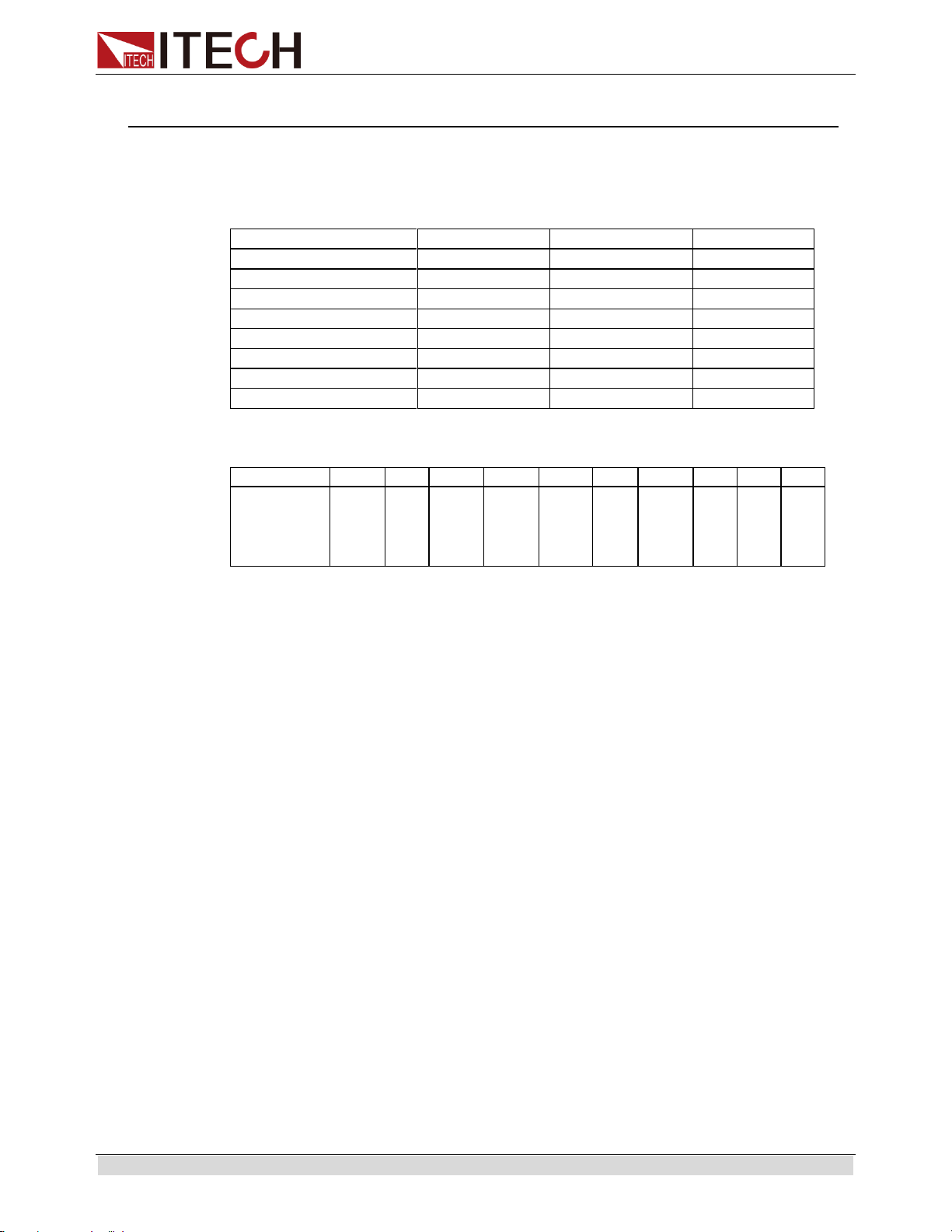
Appendix
Copyright © ITECH Electronic Co., Ltd. 39
Appendix
Specifications of Red and Black Test Lines
ITECH provides you with optional red and black test lines, which individual sales
and you can select for test. For specifications of ITECH test lines and maximum
current values, refer to the table below.
Model
Specification
Cross section
Length
IT-E301/10A
10A
-
1m
IT-E301/30A
30A
6mm
2
1.2m
IT-E301/30A
30A
6mm
2
2m
IT-E301/60A
60A
20mm
2
1.5m
IT-E301/120A
120A
50mm
2
2m
IT-E301/240A
240A
70mm
2
1m
IT-E301/240A
240A
70mm
2
2m
IT-E301/360A
360A
95mm
2
2m
For maximum current of AWG copper wire, refer to table blow.
AWG
10
12
14
16
18
20
22
24
26
28
The
Maximum
current
value( A)
40
25
20
13
10
7
5
3.5
2.5
1.7
Note: AWG ( American Wire Gage), it means X wire ( marked on the wire).
The table above lists current capacity of single wire at working temperature
of 30°C. For reference only.

Contact Us
Thank you for purchasing ITECH products. If you have any doubt about this product, please
contact us as follow.
1. Please refer to the CD-ROM of related user’s manual in package.
2. Visit ITECH website www.itechate.com.
3. Select the most convenient contact for further consultation.