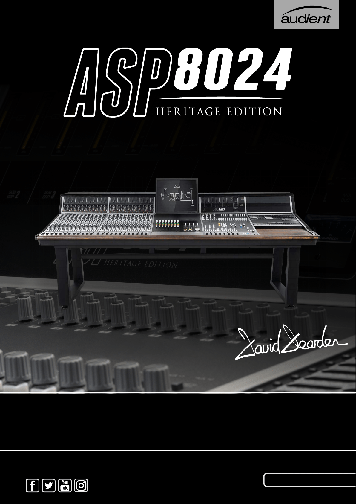
THANK YOU FOR PURCHASING YOUR
ASP8024 HERITAGE EDITION
With the ASP8024 in production for nearly 20 years, and thousands of
consoles in use around the world based upon David Dearden’s legendary
circuit blocks, we’ve returned to his roots to release the denitive version
of the ASP8024 - the Heritage Edition.
Nineteen years ago David set out to design an analogue recording console
not knowing it was destined to become a modern classic. To commemorate
Audient and David’s phenomenal achievement we have re-imagined his
timeless design with new enhancements, features and tonal options
based on his early years as a studio technician in the renowned Advision
Studios, London UK.
We have taken a great deal of pride and care in the design and manufacture
of your ASP8024-HE console with the aim of providing you with consistent
and reliable performance for many years to come. Sit back, enjoy the
experience, explore the new features and most importantly:
GET CREATIVE
A huge thank you to the Audient console team, both past & present:
David Dearden • Gareth Davies • Bill Whalley (R.I.P) • Stephen Flower •
Gerald Squires • Asif Dawe • Warren Richmond • Connie Pearce •
Neil Saunders • Simon Blackwood & The Sales Team • Harry Lewis •
Andy Allen & Daniel Mills (for his help throughout the H.E project)
Tom Waterman - Technical Director, 2016
WELCOME & THANK YOU

SAFETY WARNINGS 4
CONSOLE SUMMARY 5
PART I: CONSOLE FUNCTIONS 7
Console Function Overview 8
Input Module 9
Mic & Line Inputs 10
Bus Routing & Auxes 11
Equalisers 12
Short Faders 13
Long Faders 14
Master Module 15
Stereo EFX Inputs 16
Bus Trims & Aux Masters 17
Sub Groups 18
Heritage Output Card 19
Bus Compressor 20
Master Fader 21
Control Room 22
Live Room & Foldback 23
Communications 24
Master Meters 25
Oscillator & Solo 26
Connector Panels 27
Power Supply 32
PART II: USING ASP8024-HE 33
Introduction 34
Inline Architecture 34
Tracking 34
Getting Started 34
The Multi-Track Buses 35
Monitoring Recorded Tracks 35
Foldback 35
Tracking with Effects 35
Mixing 36
Audio from DAW to Console 36
Sub Groups 36
Adding EQ to Tracks 36
Inserts and Auxiliaries (Outboard) 36
The Mix Bus 37
Adding Mix Bus Compression 37
Capturing Your Final Mix 37
PART III: OPTIONAL EXTRAS & MODULES 39
Patchbay 40
DLC Module* 47
Producer’s Desk 48
48 Channel Bus Mod & DFA 49
VESA Screen Mount 50
Cable Entry Meter Pod 51
ASP510 Mod 52
PART IV: FURTHER INFORMATION 53
Warranty 54
Registration 55
ConsoleSpecications 56
Glossary 62
PART V: DLC MANUAL 63
* DAW specic manuals available online.
Contents

Please read all of these instructions and save them for later reference before
attempting to connect the ASP8120 Ultra PSU to the Mains AC power
source. To prevent electrical shock and re hazard, follow all the warnings
and instructions marked on the rear of the ASP8120 Ultra PSU.
• This unit is connected via its power cord to the mains safety earth.
• NEVER OPERATE THE UNIT WITH THIS EARTH CONNECTION
REMOVED .
• Check that the correct operating voltage has been set for your AC mains
supply (115V for USA / Japan or 230V for EU / UK etc.)
• Check that the fuse tted is the correct type for the selected mains
voltage.
• Always replace fuse with the correct type - 115V = T16A, 230V = T8A
SLOW BLOW (time delay) types.
• Ensure that the ASP8120 Ultra is rmly connected to the console multi-
pin HIROSE connector before powering on for the rst time.
! WARNING !
TO REDUCE RISK OF FIRE OR ELECTRIC SHOCK,
DO NOT EXPOSE THIS APPARATUS TO
RAIN OR MOISTURE.
PLEASE REFER SERVICING TO QUALIFIED SERVICE
PERSONNEL.
4
Safety Warnings
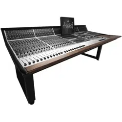
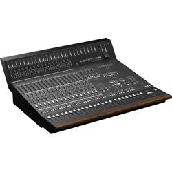
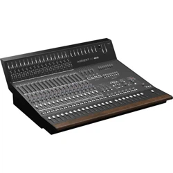
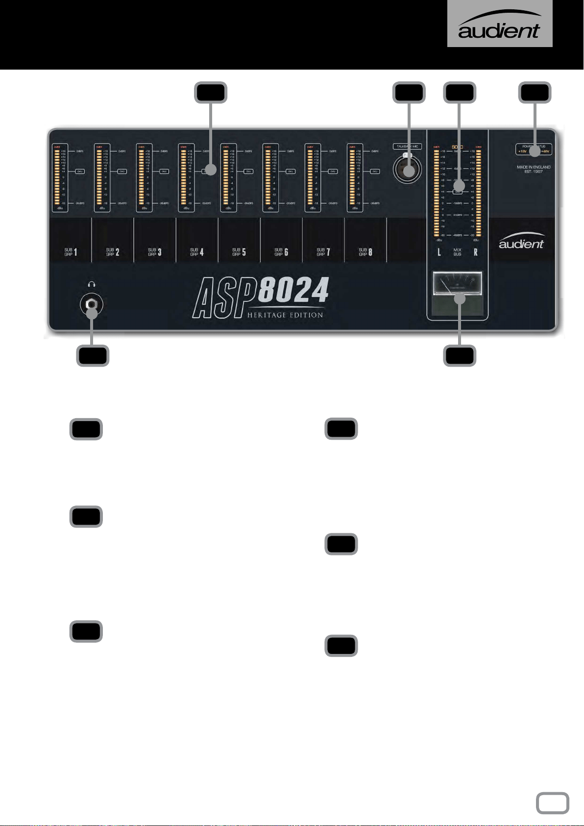
CONSOLE SUMMARY
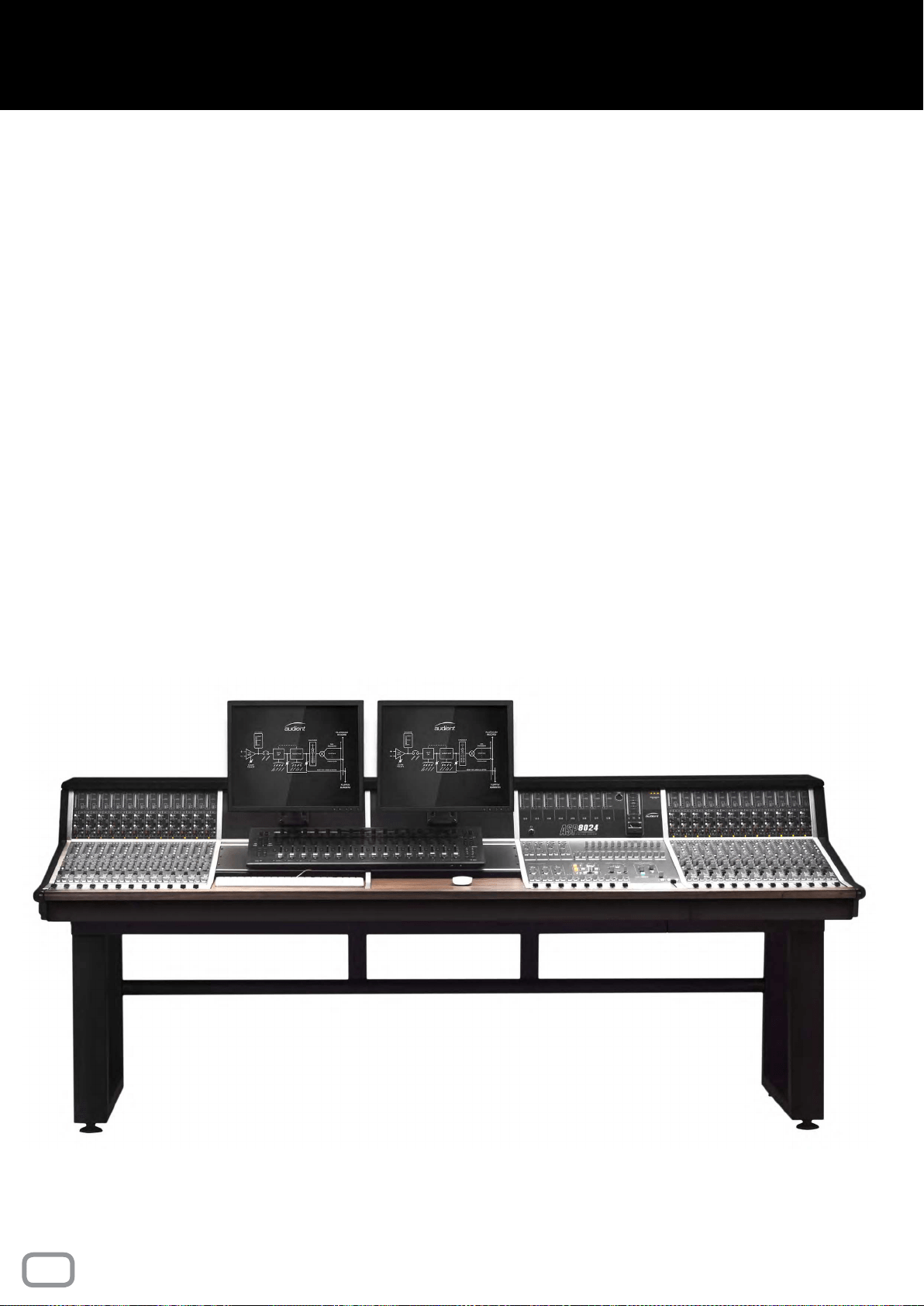
The ASP8024 Heritage Edition is a semi-modular, inline console, built
to order and lovingly constructed in our Hampshire factory by a skilled
team who’ve hand-assembled these consoles for nearly 20 years.
The ASP8024 Heritage Edition largely features the same smooth,
clean sound as the original Audient console design with its 24 Buses,
12 Auxes and 2 Cue Sends. However, we have made several key
enhancements including John Hardy
TM
990C summing ampliers, as
well as the RETRO IRON Output Card, offering tonal options on your
Mix Output.
The ASP8024-HE is a fully inline console allowing you to start building
your mixes as you’re tracking. By utilising the Long and Short Faders
simultaneously you can create separate record and monitor balances
on the same channel strip, all while being able access the consoles
split-able EQ and Aux Sends.
Heritage Edition’s inline architecture reduces the consoles footprint
while still providing incredible audio performance, complete exibility,
intuitive workflow options, as well as being a visually stunning
centrepiece for your studio.
MODULAR DESIGN
As the ASP8024-HE is a semi modular console, there are various
optional modules and extras available. These are specified when
ordering: Dual Layer Control, Patchbay, Producers Desk, VESA Screen
Mount, 48 Bus Mod and Cable Entry Pod.
5

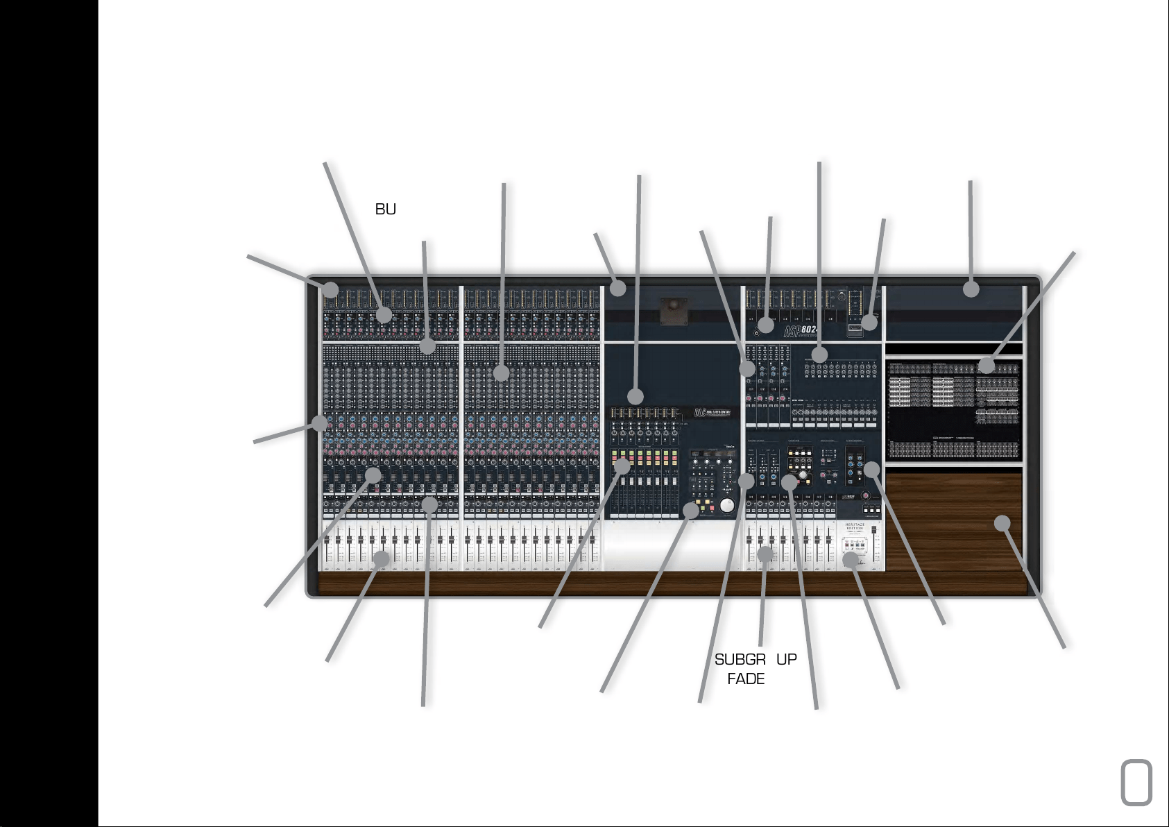
This part of the manual will take you through the functionality of
each section and individual controls on the console.
We recommend referencing the following pages when you are
unsure on how to use a feature or parameter, or would simply
like to further understand specic controls found on the console.
PART I
CONSOLE FUNCTIONS
INPUT POD
MIC, LINE &
TAPE | DAW
BUS ROUTING
MATRIX
AUX & CUE
SENDS
VESA POD
EFX
INPUTS
BLANK POD
ON-BOARD
PATCHBAY
PHONES
OUTPUT
BUS & AUX
MASTER TRIMS
G.R METER
DLC MODULE
HUI
TM
CONTROL &
VCA AUTOMATION
INPUT
METERS
4-BAND EQ
FOR LF & SF
PATHS
SHORT FADER
(SF) 60mm, PAN
& CHANNEL FLIP
LONG FADER
(LF) 100mm
DLC VCA
& HUI
TM
FADERS
SUBGROUP
FADERS
FOLDBACK
& COMMS
VCA BUS
COMPRESSOR
SCRIPT TRAY
CONTROL
ROOM
SECTION
HERITAGE
RETRO IRON
& OPTIONAL
BUS LINK
DLC DAW
TRANSPORT
& HUI
TM
CONTROL
LONG FADER
PAN & MIX
ASSIGN
8
console FUNCTION OVERVIEW
This section takes you through the Input Module, starting from the
Meters, all the way down to the Long Faders. Each channel strip
is identical in this module, therefore the following explanations
can be applied to every channel strip.
9
INPUT MODULE
METERS
The Meters show the level coming into both the Mic/
Line Input and the DAW/Tape Returns enabling you to
set a healthy signal level. They are scaled in dBu.
INSERT ACTIVE
Activates the Insert for DAW/Tape Returns, allowing you
to add outboard gear into your mixing path.
TAPE / DAW TRIM
The Trim boosts or cuts the overall level of the DAW/
Tape Returns by ±15dB. Use to gain stage input signals.
LINE
The Line Button swaps between the Mic and Line Inputs.
MTR FLIP
Flips the source of the meters. By default the large meter
shows the DAW/Tape return and the small meter shows
the Mic/Line input.
INSERT ACTIVE
Activates the insert for the Mic/Line Input.
GAIN
Applies gain to the Mic/Line Input to amplify the signal.
6 to 60dB on Mic and -14 to 40dB on Line.
POLARITY REVERSE
Inverts the signal in the Mic/Line Input. Useful if you are
recording with multiple microphones which may be out
of phase with each other.
48V
Turns on +48V Phantom Power locally for each channel
to power your microphones when needed.
HPF
Turns on the High Pass Filter to remove frequencies
below 75Hz in the Mic/Line signal.
The preamps of the ASP8024-HE use a transformerless,
eight transistor design to provide a fast, clean sound with
a little bit of colour when pushed. An insert on both the
mic and tape inputs allows you to insert outboard gear
into the recording path or the playback / mix path.
NOTE
0VU = +4dBu = 1.23Vrms = -14dBFS
CLIPPING / OVER indicates levels of +18dBu
or more.
Calibrate your converters to +18dBu = 0dBFS
for digital line up, otherwise known as +4dBu =
0VU = -14dBFS.
1
2
3
5
8
10
4
6
7
9
1
2
3
4
5
6
7
8
9
10
10
Mic & Line Inputs
BUS ROUTING SWITCHES
Assign channel signal to any of the 24 Multi-track Buses
(or 48 Buses if the 48 Channel Bus Mod is installed).
SHIFT
Offset the value of each routing switch by 12 so that
signals can access Multi-track buses 13-24.
FOLLOW PAN
Use to create a stereo bus. Bus routing will follow the
channel pan position, with odd buses providing the
left channel, and even buses providing the right.
LF
Allows you to route audio from the Long Fader path
of the channel to the multi-track buses. By default SF
(Short Fader) signals feeds the routing matrix.
SEND LEVEL (dB)
Controls the amount of signal being sent to the
corresponding Aux/Cue Bus. This can be anywhere
from -inf to 0dB. Use these to build FX sends to
reverbs etc.
SF
By default the sends are taken from the LF (Long
Fader). SF allows you to send audio from the short
fader path to the Aux Buses. This can be pre or post.
PRE
Takes the signal from before the fader (SF or
LF) rather than after, to ensure that the fader
position doesn’t affect the aux send level. Great for
headphone mixes.
7-8, 9-10, 11-12
Use these buttons to shift the send destinations to
Auxes 7-12.
1
2
3
4
5
6
7
8
The routing of the ASP8024-HE allows you to send the
signal of any given channel to any of the 24 Multi-track
Buses, giving you a huge amount of exibility at both
the tracking and mixing stage. Up to 12 Auxes and 2
Cue Sends allow you to easily utilise outboard effects
and control over artist foldback.
1
2
3
4
6
8
7
5
11
BUS Routing & Auxes
PARAMETRICS
IN
Switches the Parametric EQ into the signal path.
SF
Switches the Parametric EQ to the Short Fader path
(independent of Shelf EQ).
kHz/Hz
Controls the centre frequency of the EQ band.
BW
Stands for bandwidth and controls the how wide the
frequencies around the centre frequency. Choose a
narrow BW for surgical cuts or a wide one for more
musical boosts and cuts.
dB KNOBS
Allows you to boost or cut each frequency by ± 15 dB.
SHELVES
IN
Switches the Shelf EQ into the signal path.
SF
Switches the Shelf EQ to the short fader path
(independent of Parametric EQ).
AIR
Switches the High Frequency Shelf EQ from 10kHz
to 18kHz to add additional “Air”.
100Hz
Switches the Low Frequency Shelf from 50Hz to
100Hz to give extra punch.
dB KNOBS
Allows you to boost or cut each frequency by ± 15 dB.
1
2
3
4
5
1
2
3
4
5
6 7
8
9
10
6
6
7
8
9
10
ASP8024-HE features the classic David Dearden
4-Band console Equaliser on every channel. Offering
two dual-band equalisers that can be split individually
to the Short (SF) or Long (LF) Fader paths.
12
Equalisers
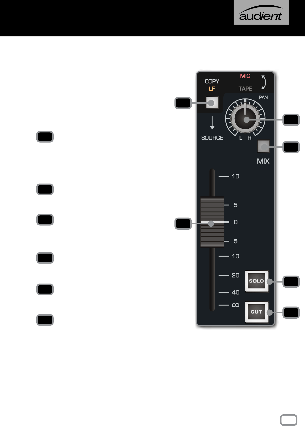
COPY LF
Selects the post fader LF signal as the input to
the Short Fader path, overriding the Mic or Tape
selection from the Flip Switch. This can be used to
ride the level of the Aux Sends on the Short Fader
(great for delay and reverb throws).
PAN
Places the signal in the stereo eld by balancing the
signal between the left and right channels.
MIX
Sends this channel to the Mix Bus. To minimise the
noise oor of the console, this should be disengaged
if the channel is not in use.
FADER
Controls the amount of signal being sent out of the
Short Fader path.
SOLO
Mutes every channel except channels that are
soloed.
CUT
Cuts the Short Fader output of that particular
channel.
ASP8024-HE is an inline console. This means that
there are both input and monitoring signal paths
on the same channel. By default, the Short Fader
contains the input signal, however you can use the
channel ip switch to switch to the tape signal.
Don’t forget that you can assign the Aux/Cue
Sends and EQ to the Short Faders by pressing the
SF buttons.
1
2
3
4
5
6
1
4
3
2
5
6
13
Short Faders
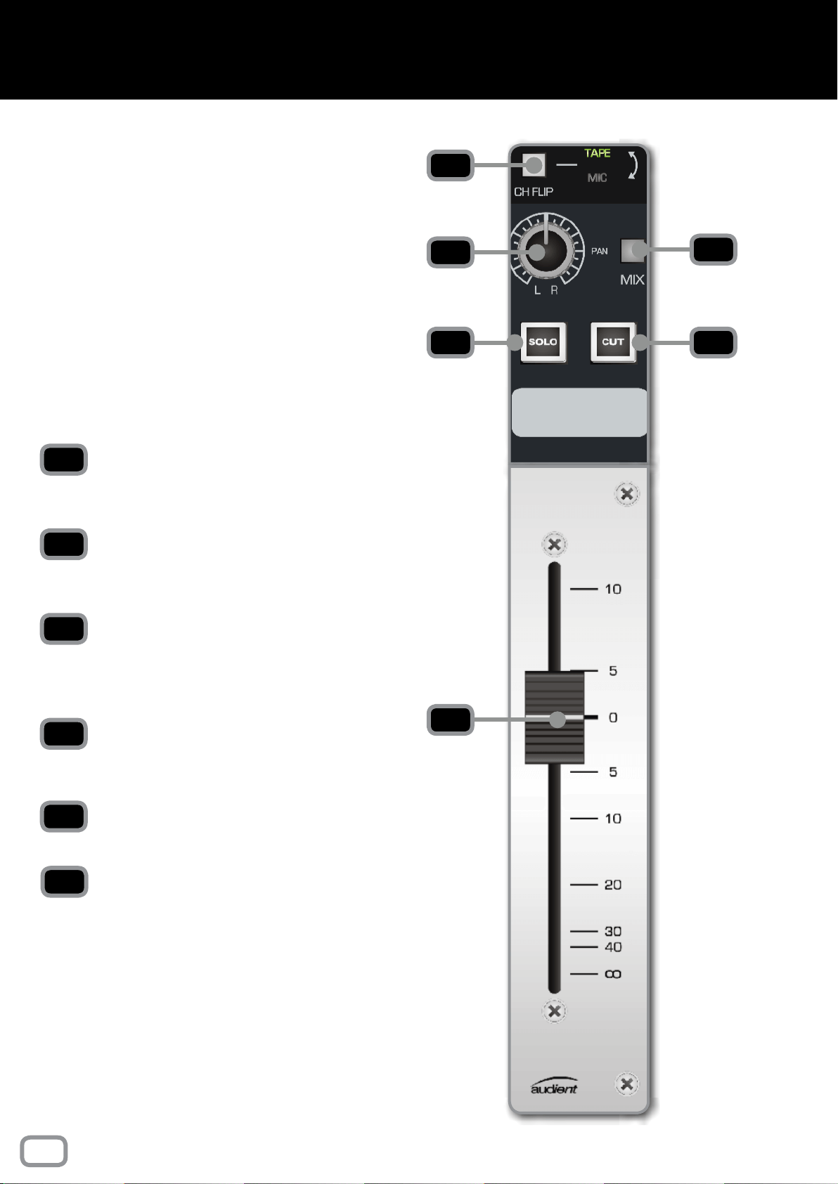
The Long Fader operates on the LF signal path and
is mainly used for creating the monitor mix and the
nal stereo mix.
The fader is expected to operate around the 0dB
mark with 10dB of gain in hand, allowing the signal
to be increased or decreased in level.
When setting levels, start with the fader at the 0dB
position, then adjust the input sensitivity control
to the correct level.
CH FLIP
Flips the channel path onto the Long Fader and the
playback path onto the Short Fader.
PAN
Places the signal in the stereo eld by balancing the
signal between the left and right channels.
MIX
Pressing this button sends this channel to the mix
bus. To minimise the noise oor of the console, this
should be disengaged if the channel is not in use.
SOLO
Mutes every channel except channels that are
soloed.
CUT
Cuts the sound output of the particular channel.
FADER
Controls the amount of signal being sent out of the
Long Fader path.
1
2
3
4
5
6
1
2
4
3
6
5
14
LONG Faders
The following section goes through the Master Module,
which handles mix bus processing, monitoring, and
communications among other things.
MASTER MODULE
15
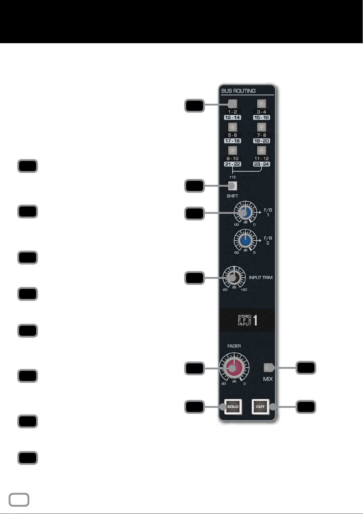
BUS ROUTING
Allows you to send the stereo inputs to any of the
Multi-track Buses. This is done in pairs as the stereo
signal takes up 2 buses.
SHIFT
Switches the functions of the routing switches
from the rst 12 Multi-track Buses to the second
12 Multi-track Buses.
F/B 1 and F/B 2
Controls the signal sends to Foldback Output 1 and
Foldback Output 2.
INPUT TRIM
Reduces or increases the signal level of the stereo
EFX Input from -20dB to +20dB.
FADER
A fader in disguise as a knob, which controls the
level being sent to the Mix Bus if the Mix Button
is engaged.
MIX
Sends the channel to the Mix Bus. To minimise the
noise oor of the console, this should be disengaged
if the channel is not in use.
SOLO
Mutes every channel except channels that are
soloed.
CUT
Cuts the sound output of that particular Stereo EFX
Input.
1
2
4
3
6
5
7 8
1
2
4
3
6
7
5
8
The Stereo EFX Inputs allow stereo signals to be
brought back into the console from an effect unit
without using up a complete channel strip.
Often stereo signals can only be routed to the
stereo mix, however, the ASP8024-HE stereo
inputs allow routing back to the Multi-track in
addition to the mix.
16
stereo efx inputs
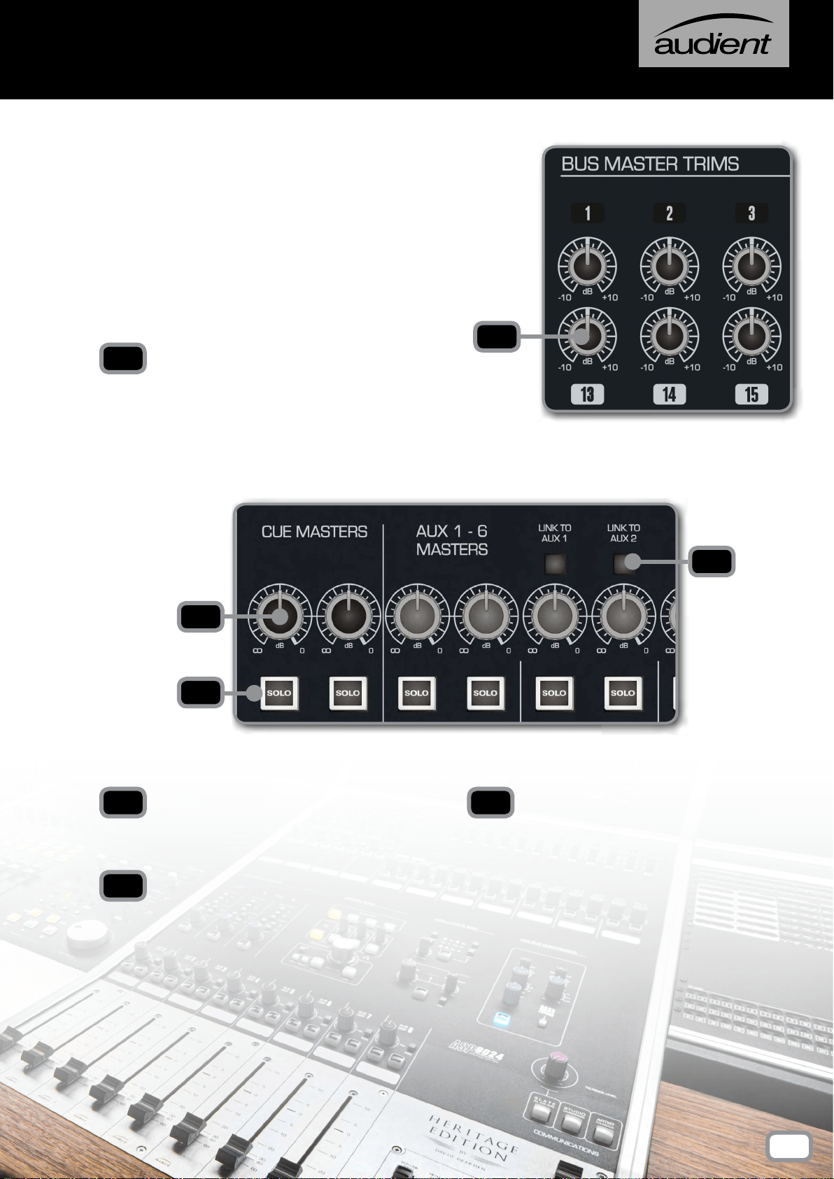
BUS MASTER TRIMS
dB KNOB
Allows you to adjust the overall level of a particular
Multi-track Bus from -10dB to +10dB.
dB KNOB
Allows you to adjust the overall level of a Cue
or Aux from -inf to 0dB.
SOLO
When engaged, all other channels and Auxes are
muted unless they also have their Solo Button
engaged. This can be useful to preview artist
mixes, or check that the correct material is being
sent to a piece of outboard gear.
The Bus Master Trims are the nal stage of level
control over the signals routed to the Multi-track
Bus outputs. Each Bus has a Level Trim although
for the purposes of this manual only a few are
shown in the accompanying diagram.
1
2
3
1
2
3
AUX LINK
Links an Aux back to either Aux 1 or 2, useful
for when you want to access the same reverb
unit from both the LF and SF paths on the same
channel.
4
4
CUE AND AUX MASTERS
17
bus trims & aux masters
PAN
Places the signal in the stereo eld by balancing
the signal between the left and right channels.
MIX
Sends the Sub Group signal to the Mix Bus. To
minimise the noise oor of the console, this should
be disengaged if the Sub Group is not in use.
SOLO
Mutes every channel except ones that are also
soloed.
CUT
Cuts the signal for the specic Sub Group.
FADER
Controls the amount of signal being sent to the
main Mix Bus, variable from -inf to +10dB.
In addition to routing signal to the Multi-track,
the rst eight buses are also sent to the 8 Sub
Groups. Each sub group has a Pan control, Solo
and Cut switches with a fader controlling the
group output level.
The Sub Groups have insert points located on
the rear panel of the console allowing external
processing to be patched in.
The Mix switch assigns the Sub Group to the
stereo Mix Bus and allows the Sub Group to be
used in mix down. The Sub Group Insert Returns
can be used as extra inputs to the mix.
1
3
2
4
5
1 2
3
4
5
18
sub groups
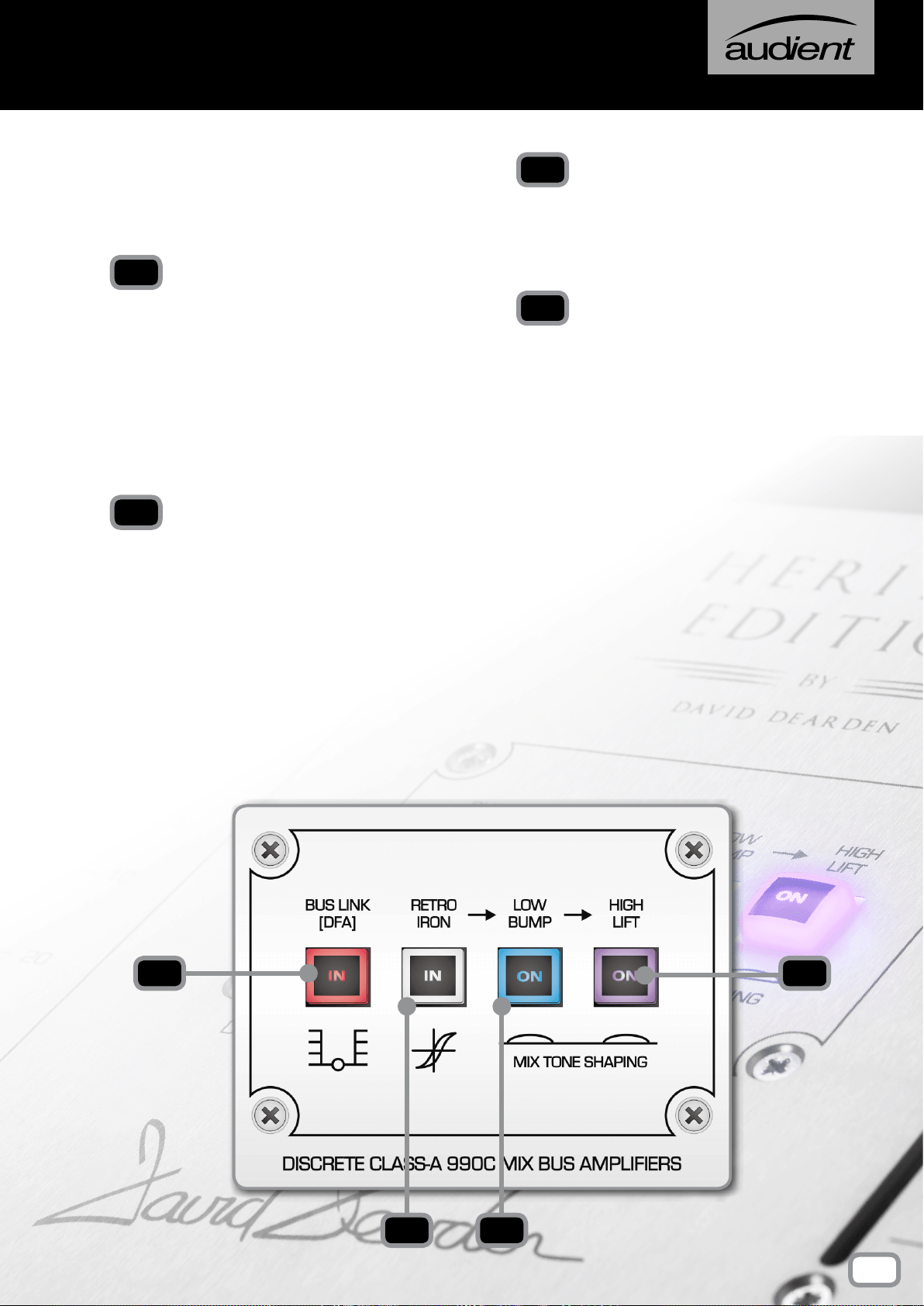
Inspired by the consoles David Dearden worked
on and built throughout his career, the Heritage
Output Card provides tonal shaping options on
your Mix Bus Output.
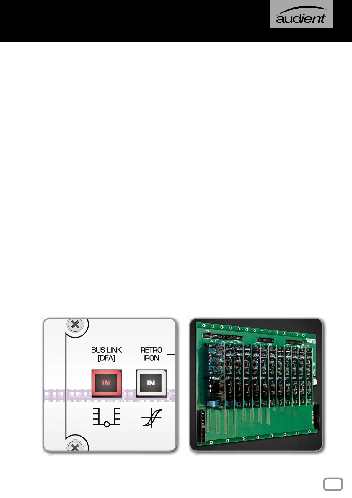
BUS LINK (DFA)
When the optional 48 Channel Bus Mod is tted
to the console, pressing the Bus Link button links
the two 24ch buses together allowing you to
use the desk as a standard 24 bus console with
exible routing. Otherwise channels 25+ only
have access to Multi-tracks 25-48.
When the 48Ch Bus Mod isn’t tted then this
button simply acts as a DFA button (look it up).
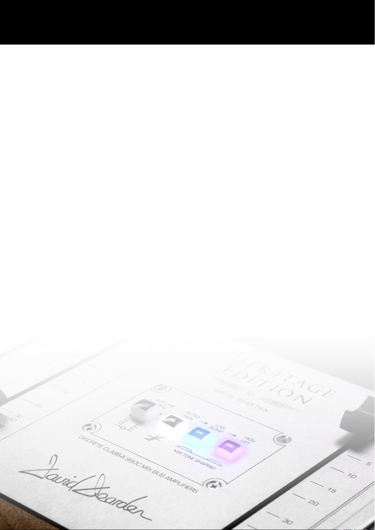
RETRO IRON
RETRO IRON introduces two Carnhill Output
transformers to the console, giving you the fat
punchy sound transformers are known for. The
two transformers are driven by a circuit inspired
by David’s time at Advision Studios.
When engaging the RETRO IRON stage, listen
for extra punch, especially in the low end. You
should nd that reverbs and room mics open
up and the sound stage will get wider and more
pronounced.
LOW BUMP
Low Bump adds a slight boost to the low-end,
around 60Hz, which helps push the kick and
bass through the mix and keep the track glued
together.
HIGH LIFT
Like the Low Bump, High Lift adds a slight boost,
this time to frequencies around 20kHz. This adds
a little bit of ‘Air’ to the mix which makes cymbals
sparkle, and adds clarity to vocals.
Please note that Low Bump and High Lift are
part of the RETRO IRON circuit and will only
affect the mix when RETRO IRON is engaged.
We would recommend adding the Retro output
halfway through a mix and then mixing into it,
adding the Low Bump and High Lift as needed
to add a little sweetness to the mix.
1
2
3
4
1
2 3
4
19
Heritage output card
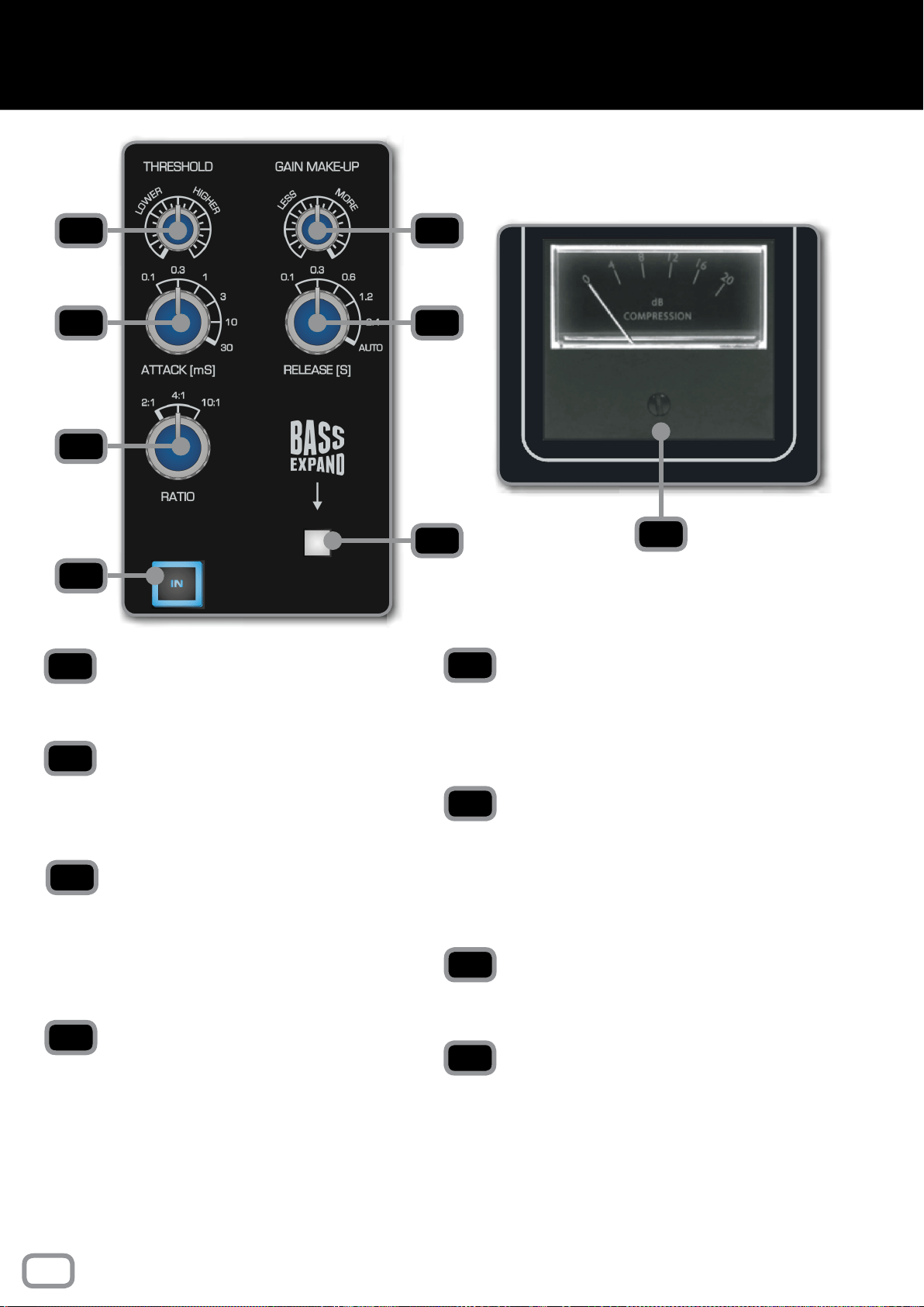
THRESHOLD
Sets the minimum amplitude needed for the
Compressor circuit to kick in.
GAIN MAKE-UP
Adds gain to the output of the Compressor to
compensate for the level lost from the dynamic
range reduction.
ATTACK
Sets how long the Compressor takes to react
once a signal passes the threshold level. Faster
attacks pick up transients but become more
noticeable. Slower attacks will miss sudden
transients but give a more subtle compression.
RELEASE
Sets how long it takes the Compressor to switch
off once the signal drops below the threshold
level. Again a faster release is more noticeable
and a slower release is more subtle.
RATIO
Sets the amount of level reduction once the
amplitude passes the threshold level. 2:1
decreases it by a factor of 2 where as 10:1
decreases it by a factor of 10.
BASS EXPAND
Adds a 350Hz high pass lter to the sidechain
meaning low frequencies don’t cause the
Compressor to activate. This stops bass
frequencies from ‘pumping’ and gives a more
full, consistent low-end.
IN
Adds the Compressor to the Mix Bus when
engaged.
GAIN REDUCTION METER
The Gain Reduction Meter displays the amount of
gain that is being reduced when the Compressor
is active.
Just getting the needle to bounce slightly is a
great trick for ‘sticking’ the mix together.
1 2
4
5
3
8
6
7
1
3
2
4
5
7
6
8
20
bus compressor
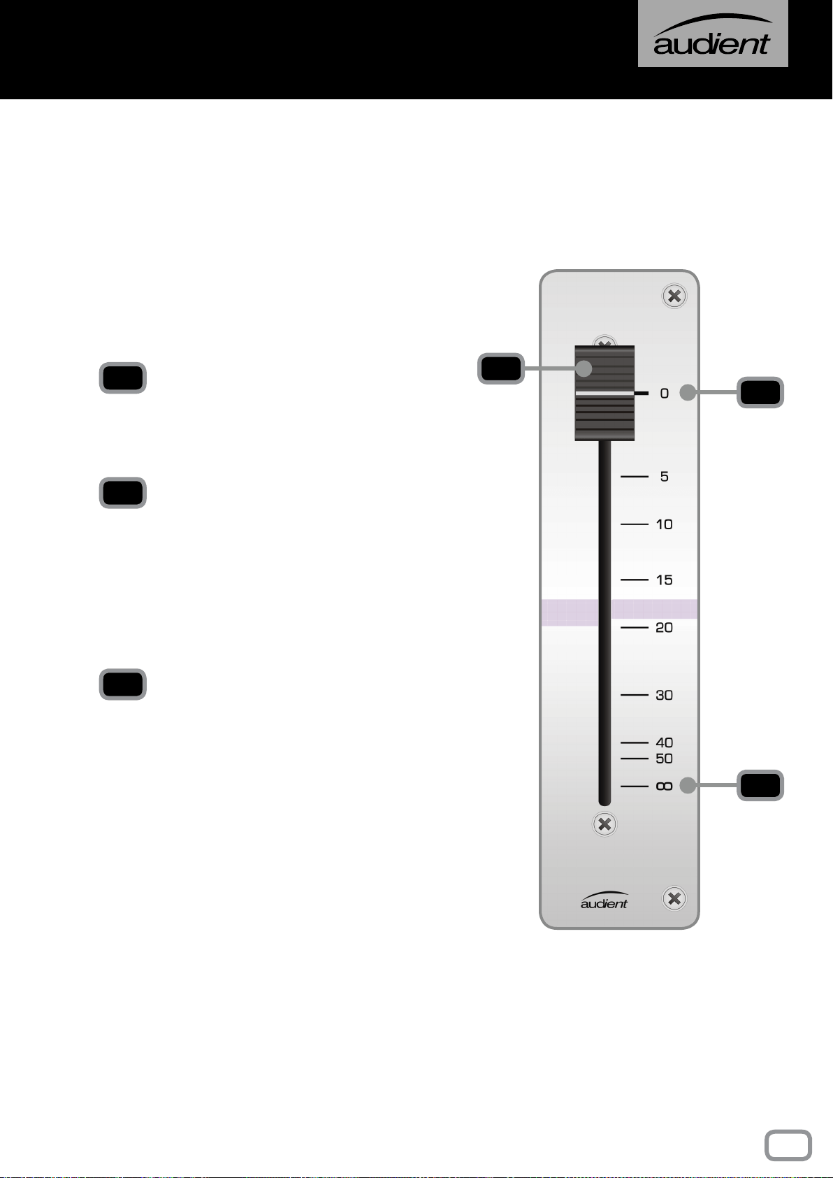
MASTER FADER
The Master Fader is used to control the stereo
output of the console.
0dB MARK
Unlike the Long Faders, it is calibrated with the
0dB mark at the top, as the main purpose of this
fader is to create a fade at the end of a track.
Under normal operating conditions, the fader
should always be set at maximum.
-INF
With the fader here, the signal path is closed and
no signal will pass.
1
1
3
2
2
3
21
Master fader
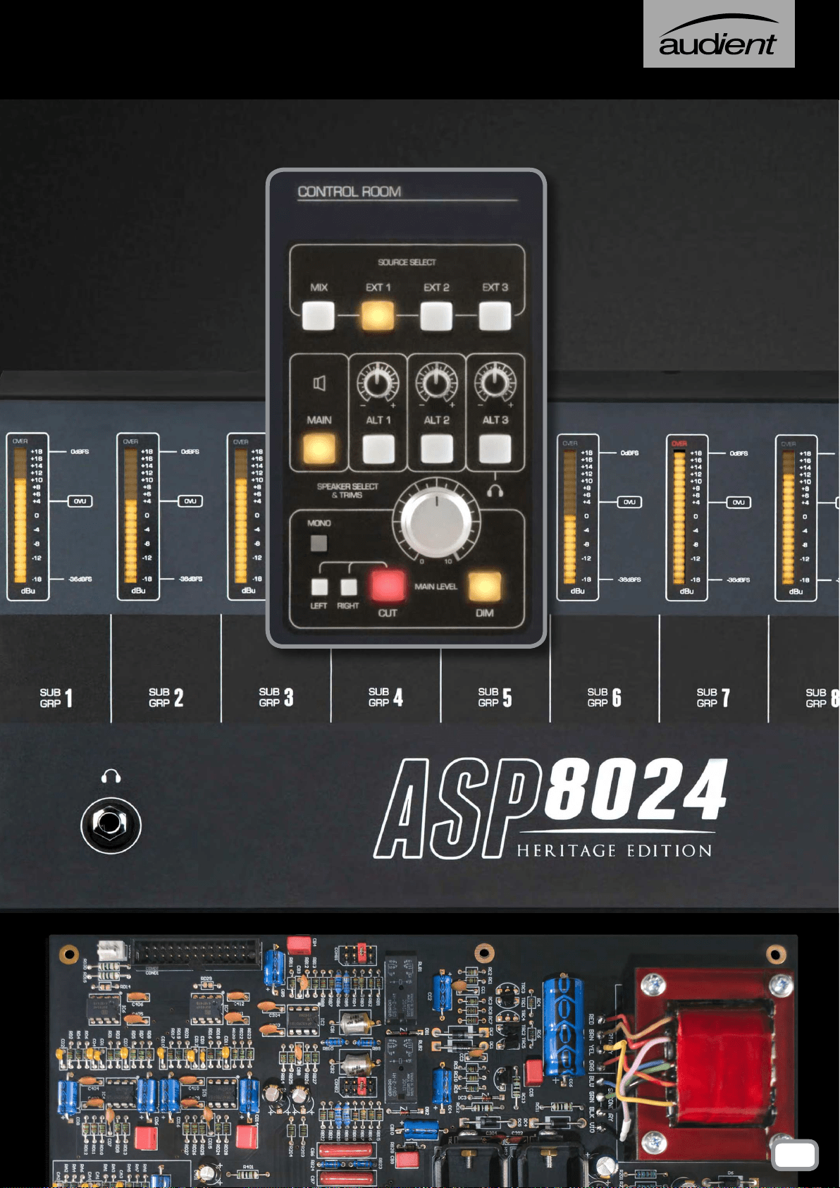
SOURCE SELECT BUTTONS
Allows you to select which source you would like
to monitor in the control room. Mix takes audio
from the Mix Bus and Ext 1-3 takes audio from
the three external inputs found in the Master
Section rear connector panel.
MAIN
Sends your selected source to the device
connected to the Main Output of the ASP8024-
HE, normally the main monitors.
ALT 1-3
Sends your selected source to one of the
Alt Monitor Outputs, Often used for smaller
monitors or ‘grotboxes’. Switching to Alt 3 will
send the output to the built in headphone
output found in the Master Meter section.
MONO
Sums the left and right channels of the monitor
output to mono in order to check the mono
compatibility of a mix.
LEFT, RIGHT, CUT
Allows you to cut either the left, right or both
monitors.
DIM
Reduces the level of the main output by a set
amount. Dim will be switched in automatically
when talkback is used to reduce the possibility
of feedback.
1
2
3
4
5
6
1
2
3
4
5
6
22
control room
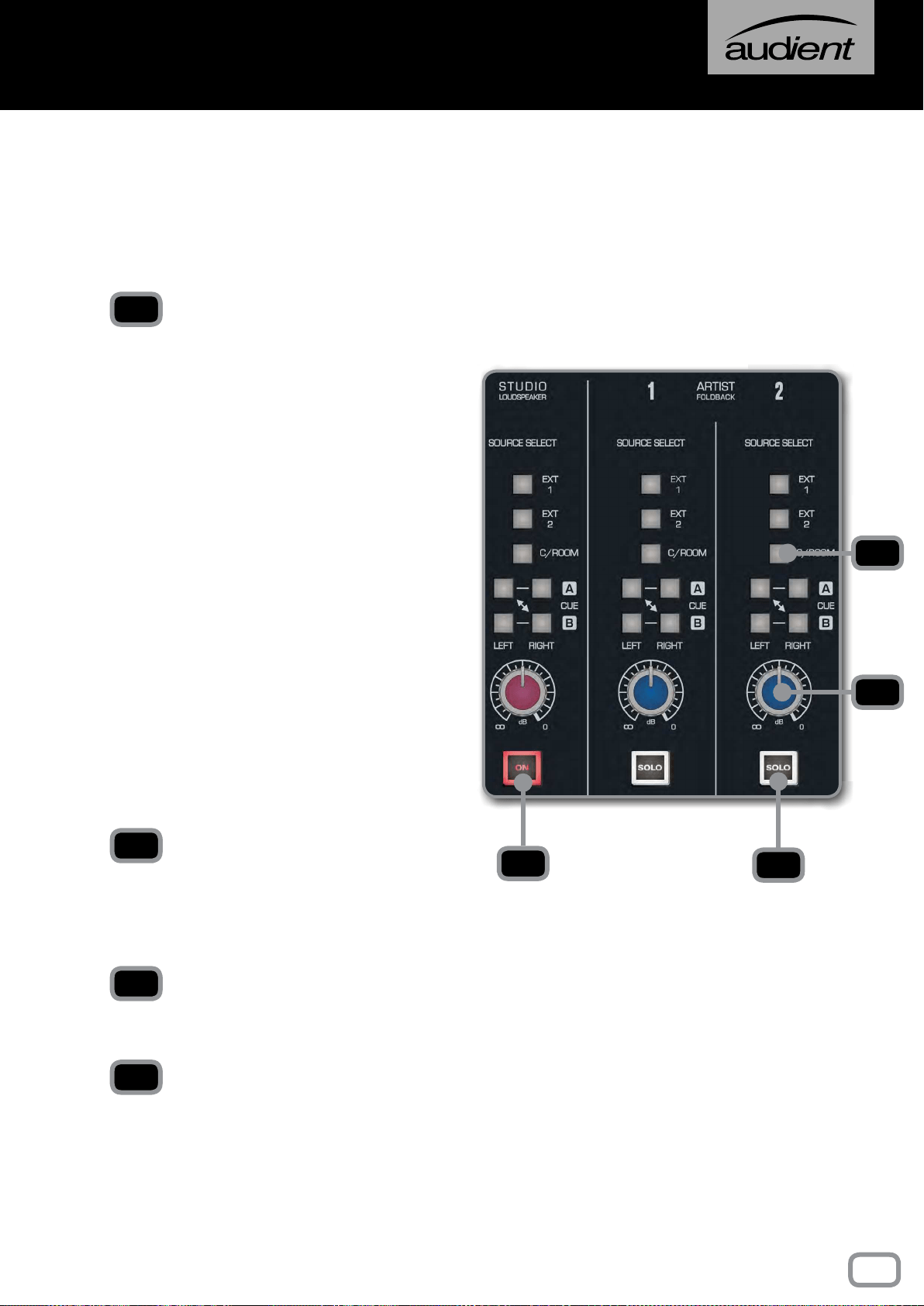
SOURCE SELECT
• EXT 1
Takes signal from External Input 1.
• EXT 2
Takes signal from External Input 2.
• C/ROOM
Takes signal from the Control Room Outputs
so your artist hears what you are hearing.
• CUE A
Takes signal from the Cue A bus. This can
either be sent to the left or right channel so
you can setup stereo or mono foldback.
• CUE B
Takes signal from the Cue B bus. This can
either be sent to the left or right channel so
you can setup stereo or mono foldback.
dB KNOB
This allows you to control the overall volume
of the foldback on the particular foldback
channel. Levels can be adjusted from -inf to
0dB.
STUDIO LOUDSPEAKER ON
Turns the studio loudspeaker in the live room
on and off.
ARTIST FOLDBACK SOLO
Cuts all other sources apart from those that
are also soloed.
1
2
3
4
1
2
4
3
The Studio Loudspeaker and Artist Foldback
section allow you to route signal to performers
from various sources on the console. In all
cases, the same sources are available.
23
live room & foldback
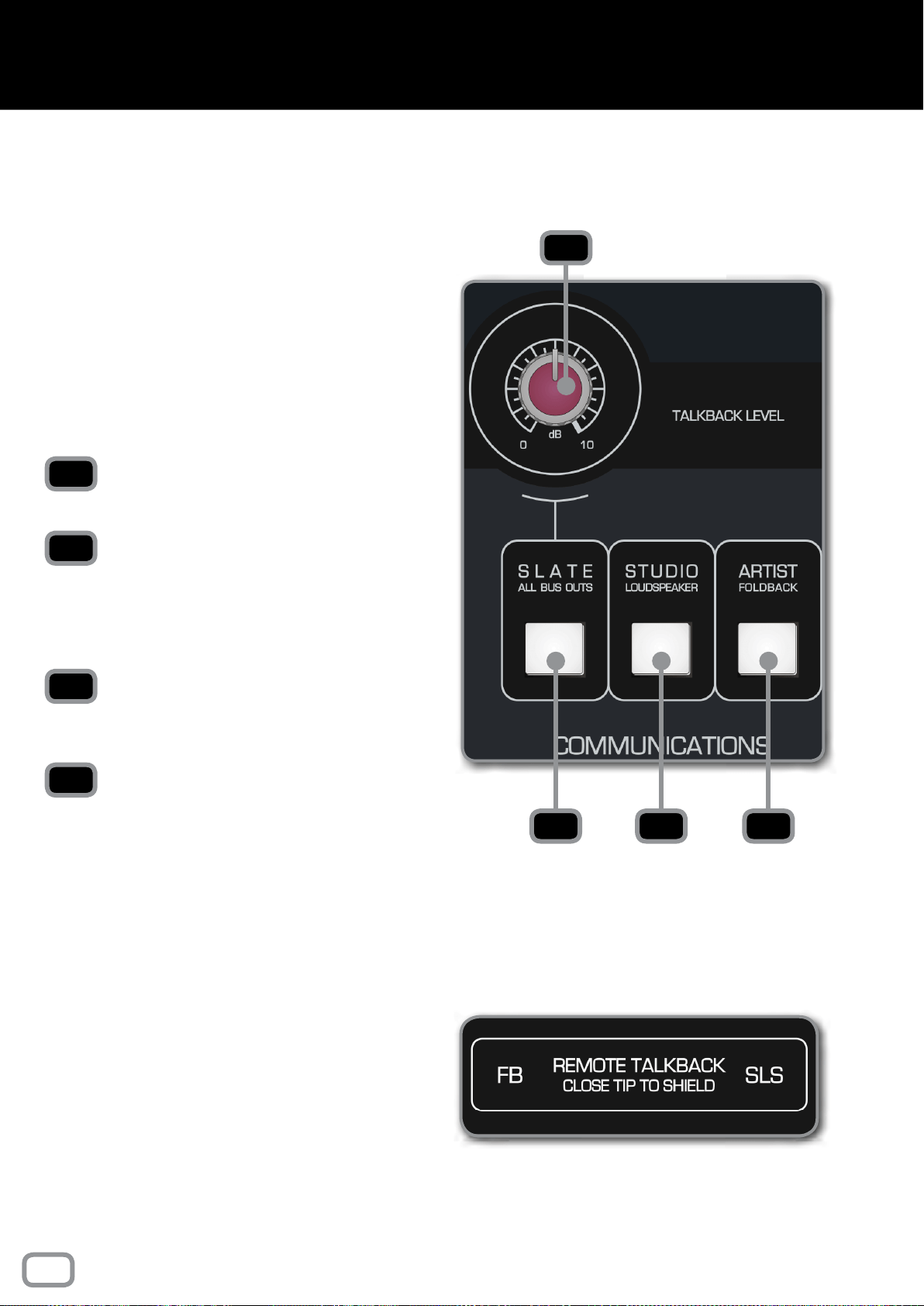
TALKBACK LEVEL
Sets the level of talkback being sent.
SLATE (ALL BUS OUTPUTS)
Sends the talkback to both the artist and all the Bus
Outputs. This means the talkback is recorded onto
the track. Great for leaving session notes and take
numbers at the start of a track.
STUDIO LOUDSPEAKER (SLS)
Sends the talkback to a set of loudspeakers in the
live room.
ARTIST FOLDBACK
Sends the talkback to the Artist Foldback Mix.
Talkback is used to communicate with the studio,
the foldback system, or the group outputs of the
console. Note that the talkback to the foldback
and studio loudspeaker systems will work even
when their respective volume controls are turned
down.
In all cases, pressing a talkback button will
cause the control room monitors to dim. This
helps prevent feedback, makes the talkback
more intelligible and does not affect the console
outputs.
1
3
2
4
1
32 4
REMOTE TALKBACK
ASP8024-HE has the option to control the Artist
Foldback and Studio Loudspeaker talkback via
latching foot switches (not provided). This lets
you talk to artists and continue using the console
without having to reach for the talkback controls.
To make use of this, you need to purchase a
latching foot switch (such as the Radial Tonebone
BigShot SW2
TM
remote foot switch).
Using a jack cable, plug the foot switch into the
Remote Talkback Connectors on the rear of the
console, to the right of the Multi-track Outputs.
24
communications
SUB GROUP METERS
The Sub Group Meters show you the post fader
signal level of the Sub Groups including an
OVER indicator to alert you should you reach
the headroom limit of the Sub Groups.
TALKBACK MIC CONNECTOR
Use this to connect any standard microphone for
talkback use. The connector has +48V Phantom
Power for use with condenser mics. Phantom
Power can be switched off by removing the
jumper at LK1 on the Master Meter circuit
board.
MAIN METERS
The Main Meters show you the level of the mix
outputs after the Master Fader. This includes
an OVER indicator to alert you if you reach the
headroom limit of the Mix Outputs.
POWER RAIL INDICATORS
Shows the current status of the power rails of
the console. If they are all lit up then all is well.
If any of the power rail lights aren’t on but the
PSU is, then it indicates that there is an issue
and we would recommend contacting us at:
HEADPHONE OUTPUT
The ASP8024-HE includes a reference grade
Headphone Amplifier which is accessed by
routing the audio to the ALT 3 outputs in the
Monitor Control Section of the console. The
headphone jack is a standard 6.35mm TRS jack.
GAIN REDUCTION METER
The Gain Reduction Meter shows you the
amount of compression that is being applied.
1
2
3
4
5
6
1 2 3 4
5 6
25
master meters
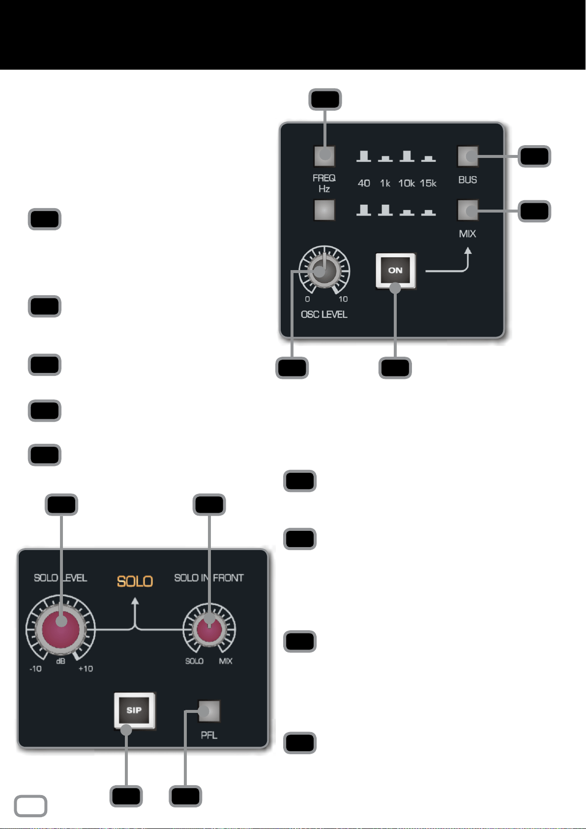
FREQ HZ
Using the two buttons, you can select
from 40Hz, 1kHz, 10kHz or 15kHz for the
Oscillator frequency using the combinations
shown on the console.
BUS
Sends the Oscillator signal to every Multi-
track Bus Output.
MIX
Sends the Oscillator signal to the Mix Bus.
LEVEL
Sets the overall level of the Oscillator.
ON
Turns the Oscillator on and off.
SOLO LEVEL
Sets the overall level of the soloed channels.
The level can be adjusted from -10dB to +10dB.
SOLO IN FRONT
Allows you to blend between the solo bus and
the Mix Bus when in AFL or PFL modes. This
means you can hear the mix behind the soloed
channels to get an idea of how they will t into
the mix.
SIP (SOLO IN PLACE)
When engaged, SIP will cut all channels to the
Mix Bus other than the soloed channels. This will
be recorded so should be used with caution but
can be a great way to cut all other tracks during
a solo section.
PFL
Stands for “Pre Fade Listen” and takes the soloed
signal before the fader so that the position of
the fader doesn’t affect the level of the soloed
channel.
1
2
3
54
1
2
3
4
5
6
7
8
9
6 7
8 9
The 4-Frequency Oscillator can be assigned
either to the Multi-Track or the Stereo Mix
Bus.
The level is adjustable and when not in use,
the Oscillator should be completely turned
off.
This is the master control area for the AFL/
PFL and Solo In Place system. If SIP is not
illuminated then the console will either be in
AFL or PFL mode depending on the AFL/PFL
switch.
26
OSCILLATOR & SOLO
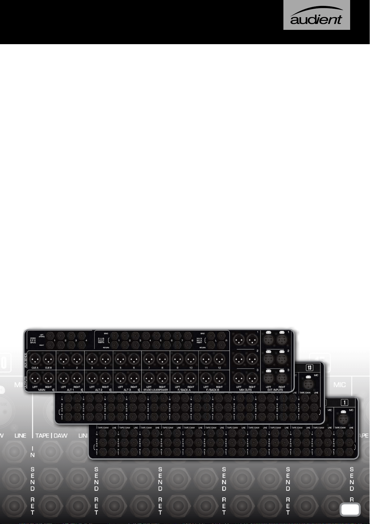
The Connector Panels are the points at which the ASP8024-HE
connects to the rest of the Studio.
The inputs and outputs use advanced, electronically balanced or
ground sensing topologies and are tted with extensive RFI rejection
networks.
All signal interfaces are also fully protected against accidental misuse,
e.g. by the connection of phantom powered cables.
We use high quality Neutrik
TM
XLR connectors and Cliff
TM
TRS Jacks
for all the connections to ensue that your signal quality is never
compromised.
CONNECTOR PANELS
27
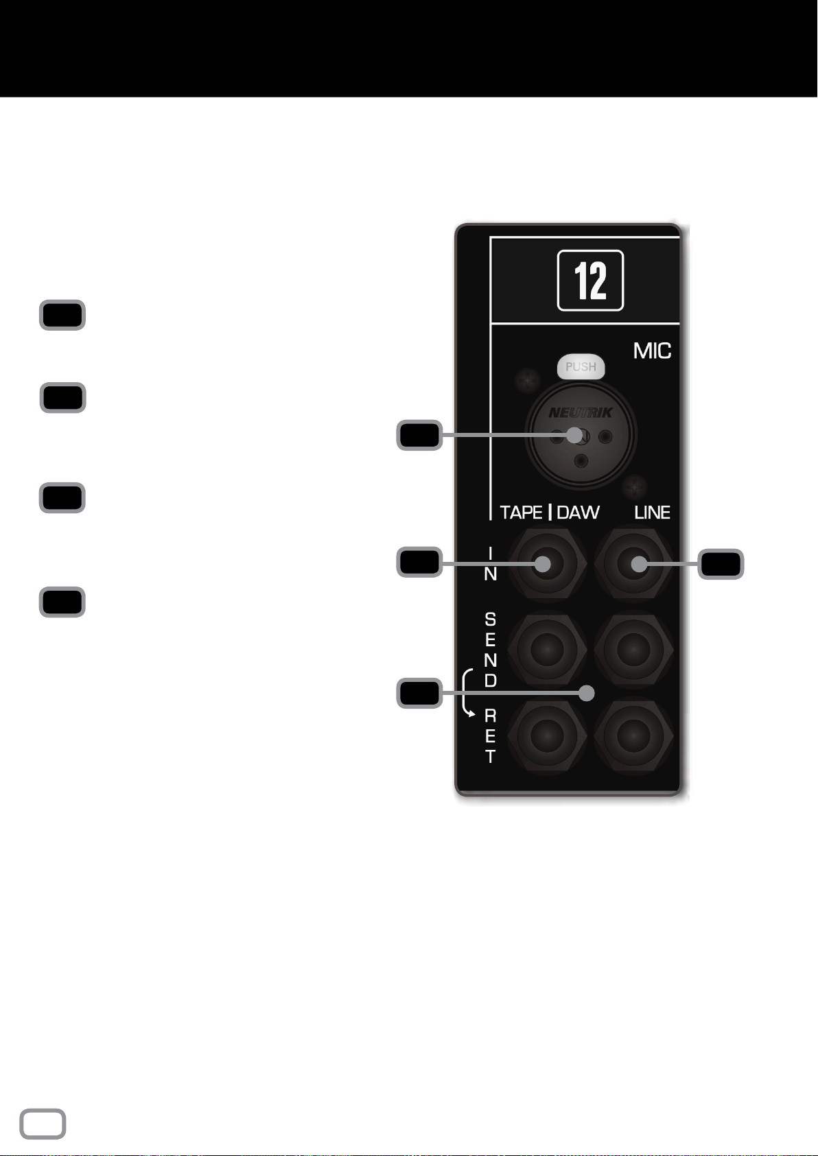
MIC
Microphones or other low level equipment can be
connected to this input.
LINE
The Line Input can be selected in place of the
Microphone Input. This input is designed for
higher, line level signals.
TAPE/DAW INPUTS
The output of your converters/tape machine
should be connected here. This input is designed
for line level signals.
SEND / RET
There are two insert points per channel, with the
Tape/DAW Insert on the left and the Mic/Line
Insert on the right.
The Insert Points are half-normalled so the sends
can be used as extra outputs without breaking the
signal path. Plugging a jack into the return breaks
the signal path so be careful not to plug a jack in
without a piece of gear attached.
Please note that the insert points aren’t affected
by the Flip Switch.
NOTICE
Please note that if you have the Patchbay module tted,
the rear Connector Panel will only have the Mic and Line
Inputs; the inserts and Tape/Daw Returns can be accessed
via the patchbay module.
For more information, please see the Patchbay Section
of this manual.
The rear mounted Connector Panel is where the
input, output and insert point connectors are
located.
The Microphone Input uses an XLR Connector,
while the Line Input, Tape Input and the Insert
Sends and Returns use Tip, Ring and Sleeve jacks.
1
2
3
4
1
3
4
2
28
connector panels
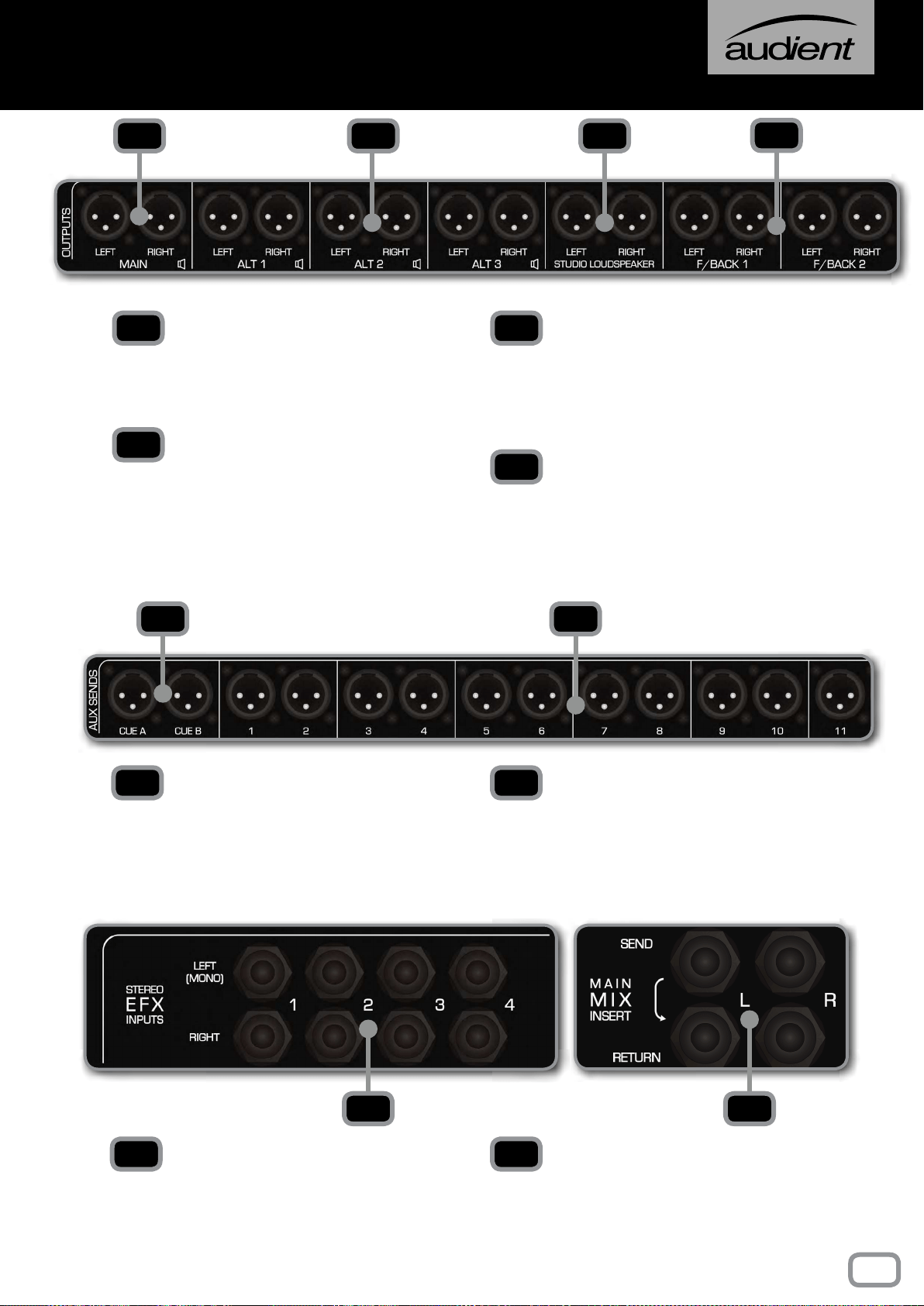
MAIN
Connect your main monitors here. This output
is at line level so you will need an amplier for
passive monitors.
ALT 1, 2, 3
Allows you to connect up to three alternate
pairs of monitors. These can be accessed
through the ALT 1, ALT 2 or ALT 3 button
in the control room section of the Master
Section.
STUDIO LOUDSPEAKERS
Here you can connect a pair of loudspeakers
which can be used to address artists in the live
room. Again this is line level and an amplier
will be needed for passive loudspeakers.
FOLDBACK 1, 2
These two stereo sends that are used for
artist foldback. They can be connected to a
headphone amplier with multiple outputs if
more than two artists require foldback.
CUE A, B
Sends the Cue Mix to outboard gear, usually
the Cue Mixes are used for foldback but can
be used for processing if required.
AUX SEND 1-12
Sends the signal from the 12 Aux Mixes to
either outboard, foldback or whatever else
you would like the Aux Sends to go to.
STEREO EFX INPUTS 1-4
Gives you four stereo inputs for the returns
from stereo outboard equipment such as
reverbs, compressors or delays.
MAIN MIX INSERT
The Main Mix Insert allows you to insert
outboard gear into the Main Mix between the
Heritage Card and the VCA Bus Compressor.
1 2 3
4
1
2
3
4
5 6
5 6
7 8
7 8
29
connector panels
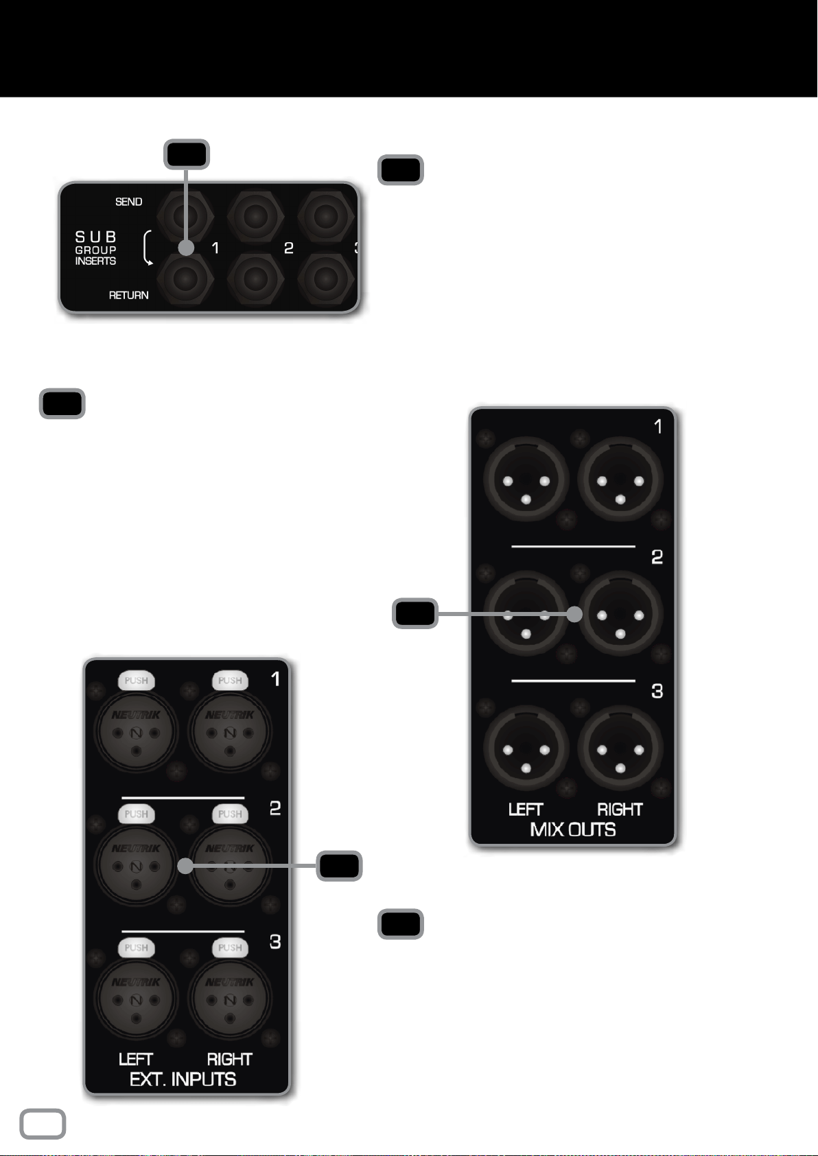
MIX OUTS 1, 2, 3
After the Master Fader, the stereo Mix Bus is
sent to three Mix Outputs. These can be sent
to anything that is capable of capturing a stereo
signal.
Having three separate Mix Outputs means you
can capture up to three copies of the mix at the
same time.
EXTERNAL INPUTS 1, 2, 3
The three External Inputs allow you to monitor
up to three additional inputs as well as the stereo
Mix Bus. This could be anything from a CD
player, a MP3 player or even a sidecar console.
2
3
2
3
1
SUB GROUP INSERTS 1-8
This panel carries the connectors for the Sub
Group Insert Points. There are 8 Sub Groups
and each has a Send Output and a Return Input.
Signal is always present on the Send Output. If
required, the Insert Returns could be used as
very basic inputs to the stereo mix bus during
mixdown, from a submixer or sampler for
example.
1
30
connector panels
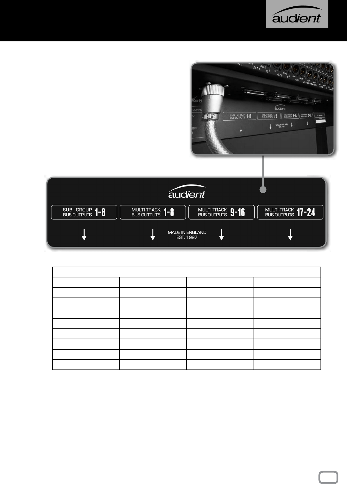
This panel contains the connectors for the
Multi-track Bus Outputs. Rather than having
individual connectors for each output, multi-
pole connectors are used for fast and easy
installation.
The Multi-track Bus Outputs are split across
3 connectors, each carrying the outputs for 8
tracks. The Sub Group Outputs are on a fourth
connector. All of the connectors follow the
Tascam DB25 wiring standard.
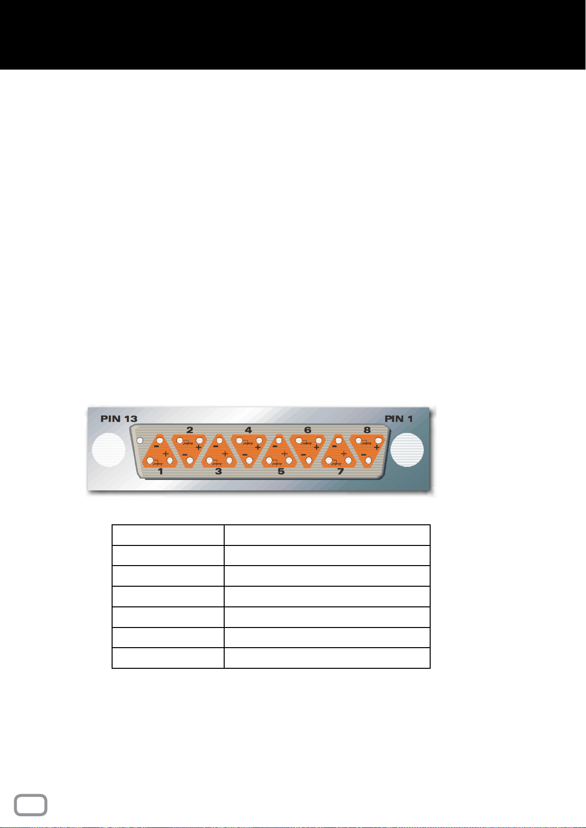
MULTI-PIN CONNECTIONS
SIGNAL NUMBER +VE SIGNAL -VE SIGNAL SCREEN
1 / 9 / 17 24 12 25
2 /10 /18 10 23 11
3 / 11 / 19 21 9 22
4 / 12 / 20 7 20 8
5 / 13 / 21 18 6 19
6 / 14 / 22 4 17 5
7 / 15 / 23 15 3 16
8 / 16 / 24 1 14 2
NOTE: All undesignated pins are unconnected. All screen connections are joined inside
the console and connected to metalwork earth.
PATCHBAYS: Tie lines connections 25-32 etc follow the same wiring convention shown
above.
31
connector panels
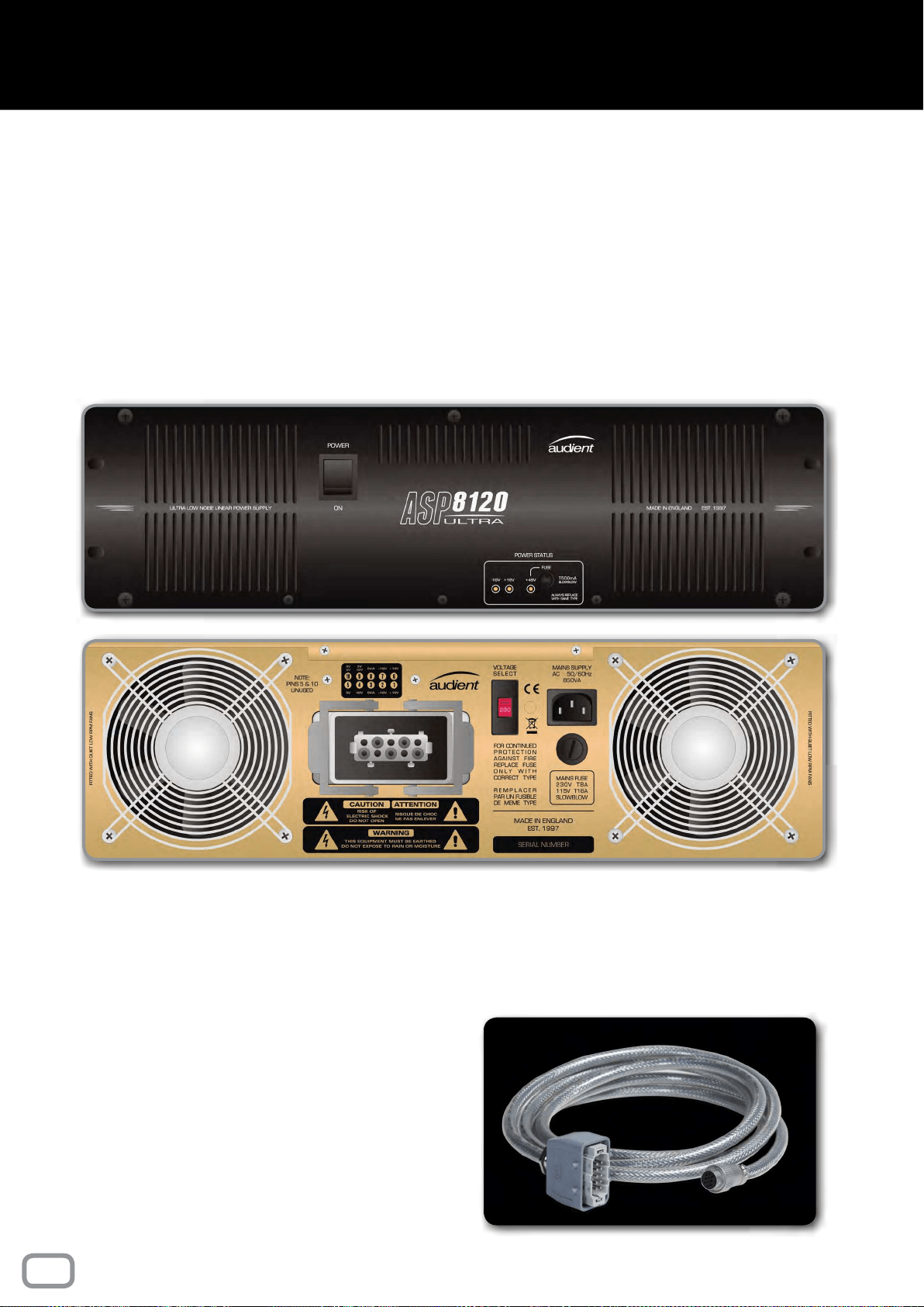
The console is powered by the ASP8120 Ultra,
rack-mounted power supply. On the front you
will nd the power switch for the entire console,
three LED indicators and the +48V fuse.
The power supply uses extremely low noise fans
and transformers, meaning that the PSU can be
placed in the same room as the console without
producing distracting noises.
On the rear of the power supply you will nd a
IEC socket, a mains voltage selector, a mains fuse
and the connector for the console power cable.
Before powering on the power supply, make
sure that the voltage selector switch is set to
the position that reects your country’s mains
voltage.
To connect the console’s power cable, simply
push the connector into the socket and then
pull the two retaining arms over the connector
until you feel a small click.
Ensure that the two cooling fans aren’t restricted
in any way, otherwise it could cause the power
supply to overheat.
The unit doesn’t require any space above or
below it when racked up and can be placed
directly on the oor.
The console is supplied with 4 meter, shielded
power cable.
The LED indicators show the current status
of the +18V, -18V and +48V Power rails, if
the LEDs are lit then it means that the rails
are working as they should. Similar power rail
indicators can be found in the master meter
section of the console.
Should you need to replace the fuse on the front
panel of the PSU, be sure to use a 500mA Slow
Blow type fuse.
32
power supply

This part of the manual explains how the features of the console
can be used in an typical recording session. If you are new to
recording or even just new to a console workflow then this
section will give you the starting points you need to track and
mix a project.
Although this section gives suggestions on how the console
can be used, it doesn’t contain any hard fast rules so feel free
to experiment and find your own workflow when using the
ASP8024-HE.
USING ASP8024-HE
PART II

INTRODUCTION
Recording is generally a three stage process
made up of the tracking stage, the editing stage
and then the mixing stage.
The tracking stage consists of capturing the
audio onto a storage medium. Traditionally
audio was captured onto multi-track tape,
however now the majority of people will use a
Digital Audio Workstation (DAW) such as Logic
or Pro Tools.
The editing stage involves preparing audio for
mixing, this usually involves everything from
trimming, editing and fading audio, to tuning
parts and more. This is where the monitoring
section of the console really comes into its own,
allowing you to quickly solo and cut channels
out of your monitoring mix.
The third stage of the process involves
returning the recorded tracks from your DAW/
tape machine back into the console. Using the
faders and EQs, you can mix the audio until the
individual tracks come together as a collective
whole. Once you are happy with your mix,
you can combine it into a stereo mix using the
analogue mix bus processing of the ASP8024-
HE.
Summing can also be done in your DAW
but you may nd that summing through the
console adds a little more colour and punch to
the overall mix, especially when fed through
the discrete 990 op-amps and Heritage Card
tonal options.
INLINE ARCHITECTURE
The ASP8024-HE uses an inline architecture,
which means the Mic/Line Inputs and the
DAW/Tape Returns are both situated on the
same channel strip; these two paths are known
as the Short Fader (SF) and the Long Fader (LF)
paths.
Inline architecture allows you to split the
various sections of the channel strip between
the two signal paths. For example, you could
use the Shelf EQs to add a high frequency
boost to a vocal during tracking and then use
the Cue sends to send the same Mic/Line
signal to a fold-back mix. At the same time you
could be using the Parametric EQs to cut out a
room noise on the DAW/Tape Return path and
using one of the Auxiliaries to send the DAW/
Tape return signal to a reverb unit.
To split the channel strip, each section has a
button which allows you to place it on either
the LF path or the SF path. The bus routing
switches by default are on the SF path, while
the Auxiliaries, Cues and EQs default to the LF
path. Furthermore, it is possible to ip the two
signal paths so that Mic/Line signal is sent to
the LF path and the Daw/Tape Returns are sent
to the SF path.
TRACKING
GETTING STARTED
A new project usually starts off with a blank
session in your DAW or with a blank roll of
tape. The rst step is to get a signal into the
console from the microphone or instrument. To
do this, connect the microphone or instrument
to the Mic/Line Inputs of your console. If you
are using the TRS Line Input, press down the
Line button on the channel you are using. If
you are using a microphone that requires +48V
Phantom Power then make sure that the red
‘+48V’ button is engaged. You should always
mute that channel, and your Speaker and
Headphone Outputs before engaging Phantom
Power as there can be a loud popping noise.
By default, the large Channel Meters show the
level of the LF path, pressing the MTR button
will ip this to allow you to accurately see the
level of the inputs. To set the level, turn the
Gain Knob, making sure to avoid overloading
the channel (indicated with the OVER light
above the meter).
34
Using asp8024-HE

THE MULTI-TRACK BUSES
For simple sessions, it is typical to route the SF
channel path to its corresponding Multi-track
Output using the Bus Routing Matrix. This
sends the signal to your recording device.
To control the amount of level being sent to
the output simply bring up the Short Fader
to a point where you get a healthy signal into
your recording device. Setting the fader at
0dB means that the signal isn’t boosted or
attenuated when it is sent to the Multi-track
Outputs, which is ideal for most situations.
However, you can also use the Short Fader in a
more creative manner:
If you are using multi-track tape machine
instead of a DAW, slightly increasing the level
of your Multi-track Outputs via the Short Fader
can give you pleasing magnetic saturation. This
isn’t applicable to all recording scenarios, but
when used well, can give you a warm, punchy
sound that is great on drums and guitars.
In a similar vein, you can use the Short Fader
to reduce the output, allowing you to increase
the gain of the preamp. Although the Audient
preamp design is relatively clean, it does start
to tighten up and get slightly ‘warmer’ as you
start to push it harder. Again, while this isn’t
suitable for all situations, it can be a great
way of adding additional richness or body to a
recording.
MONITORING RECORDED TRACKS
To monitor your recorded tracks from your
recording device (DAW/Tape machine) bring
up the Long Faders and press the Long Fader
Mix button. This sends the audio to the Mix Bus
which is then sent to the monitors. This enables
you to monitor what is happening in your DAW
on the Long Faders and lets you start building
a mix as you’re tracking, all without making
changes to your input signals.
FOLDBACK
You can use ASP8024-HE’s two Cue Mixes,
to allow musicians to hear the live input and
click/guide tracks from your session.
To bring a click/guide track onto the console,
it needs to be sent to the DAW/Tape Returns
on a channel (or multiple channels). This brings
the signal onto the LF path of that channel.
To help keep your session easy to navigate,
it is recommended that you keep the guide
tracks separate from the recording channels
(e.g. bring them in on the last channels on the
console).
To send the click/guide track, turn up the Cue
Mix knobs on the channels you want to send.
The Cue Mix knobs default to the LF path, so
to send the live input to the artist, make sure
the SF button is engaged next to the Cue mix
knobs. Use the Cue Mix Solo button found
on the Master Section to monitor what will
be sent to the artist, and then ensure the Cue
Mix Master is turned up.
The Cue Mix can be routed to the Foldback
Output using the “Live Room and Foldback
Section” of the Master Section. Press the Cue
buttons under Foldback 1 to assign the Cue
Mix to the Foldback Output. It is possible to
create a stereo foldback signal using the two
cue mixes, using Cue A as the left channel,
and Cue B as the right channel.
TRACKING WITH EFFECTS
When tracking, it is possible to make use
of the console EQ as well as using Channel
Inserts, allowing you to commit effects as
you record. To insert a piece of equipment,
press the Insert Active button in the Mic/Line
section of the channel strip. For EQ, ensure
that the SF and IN buttons are engaged on the
EQ band that you want to use. It is possible to
split the Shelf and Parametric EQs between
the Long and Short Faders by sending only
one to the SF path.
35
Using asp8024-HE

MIXING
GETTING AUDIO FROM DAW TO CONSOLE
Recorded tracks should be brought back onto
the console using the DAW/Tape Returns,
which come in on the Long Faders by default.
Ensuring that the MTR ip buttons are
disengaged, signal should appear on the long
meters for each active channel strip.
Engage the Mix buttons for the Long Faders
and bring up the faders to 0dB for channels
that are in use. Signal should now appear on
the main meters in the master section, and you
should be able to hear the recorded tracks.
SUB GROUPS
ASP8024-HE has eight subgroups, which
allows you to group certain tracks together
and give you control over their overall level
(drums channels for example). Sub Groups can
be set by using the rst eight buttons of the
Bus Routing Matrix at the top of the channels,
ensuring that the Bus Routing is ipped to the
LF path by pressing the LF button next to the
switch matrix.
To create a stereo sub-mix, press the Follow Pan
button. This causes the odd Multi-track Buses
to take signal from the left side and the even
numbers from the right. For example, on each
channel, you would press down a pair of Multi-
track buttons such as 1 and 2. Any channel that
is panned fully left will appear on Sub Group 1,
and any channel panned fully right appears on
Sub Group 2, with channels panned in between
being split between Sub Groups.
ADDING EQ TO TRACKS
EQ can be added to channels to allow them to
sit better together, or just for creative purposes.
To do this, press the IN button on the band of
EQ you want to add to the channel.
For more broad equalisation, the Shelving EQs
are best and allow you to add additional low end
or high frequencies to that track. The Parametric
EQs allow you to sweep frequencies and adjust
the bandwidth of the EQ. This gives you more
control over what is being cut or boosted and is
great for surgical cuts of problem frequencies.
INSERTS & AUXILIARIES
(USING OUTBOARD EQUIPMENT)
There are a few different ways to connect
outboard equipment to the desk, depending
on how you want the outboard to affect your
audio.
The rst way is to add the outboard gear in the
channel insert point. This means the outboard
can only affect the channel it is placed on.
Connect your outboard gear between the
insert send and return, then press the ‘Insert
In’ on the DAW/TAPE inputs to send the signal
through the gear. The Sub Groups can also
have gear inserted in the same way, useful
when wanting to process a group of channels
as a whole.
Another way of using outboard effects is to
use the auxiliaries. This allows you to send
multiple channels of audio to the same piece of
outboard gear, while not affecting the original
audio. The Aux Send level knobs allow you to
alter the amount of signal being sent to the
auxiliary from each channel. The output of
the outboard can be fed back into the console
either through an unused input channel, or one
of the Stereo EFX Inputs.
When using an Auxiliary, ensure that the
corresponding Aux Master is turned up in the
Master Section of the console. The Aux Master
Solo buttons can be used to monitor what is
being sent to the outboard gear.
36
Using asp8024-HE

THE MIX BUS
The Mix Bus is the two channel bus that your
mix is summed into. On the ASP8024-HE,
the summing bus is active and uses a pair of
Jenson
TM
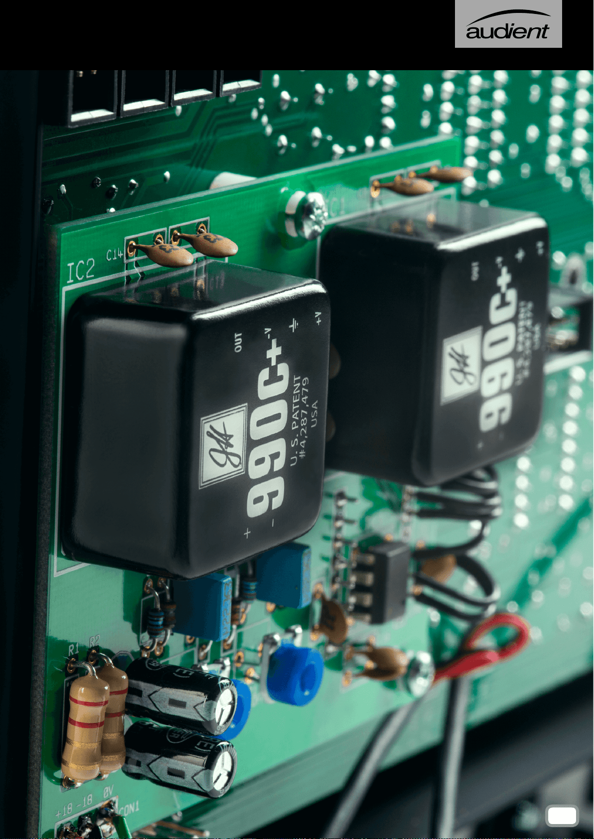
990C+, fully Discrete Op-Amps. This
offers a fast punchy sound, minimal crosstalk
and an extremely low noise oor. This then
runs into the Heritage output card, which gives
additional tone shaping options.
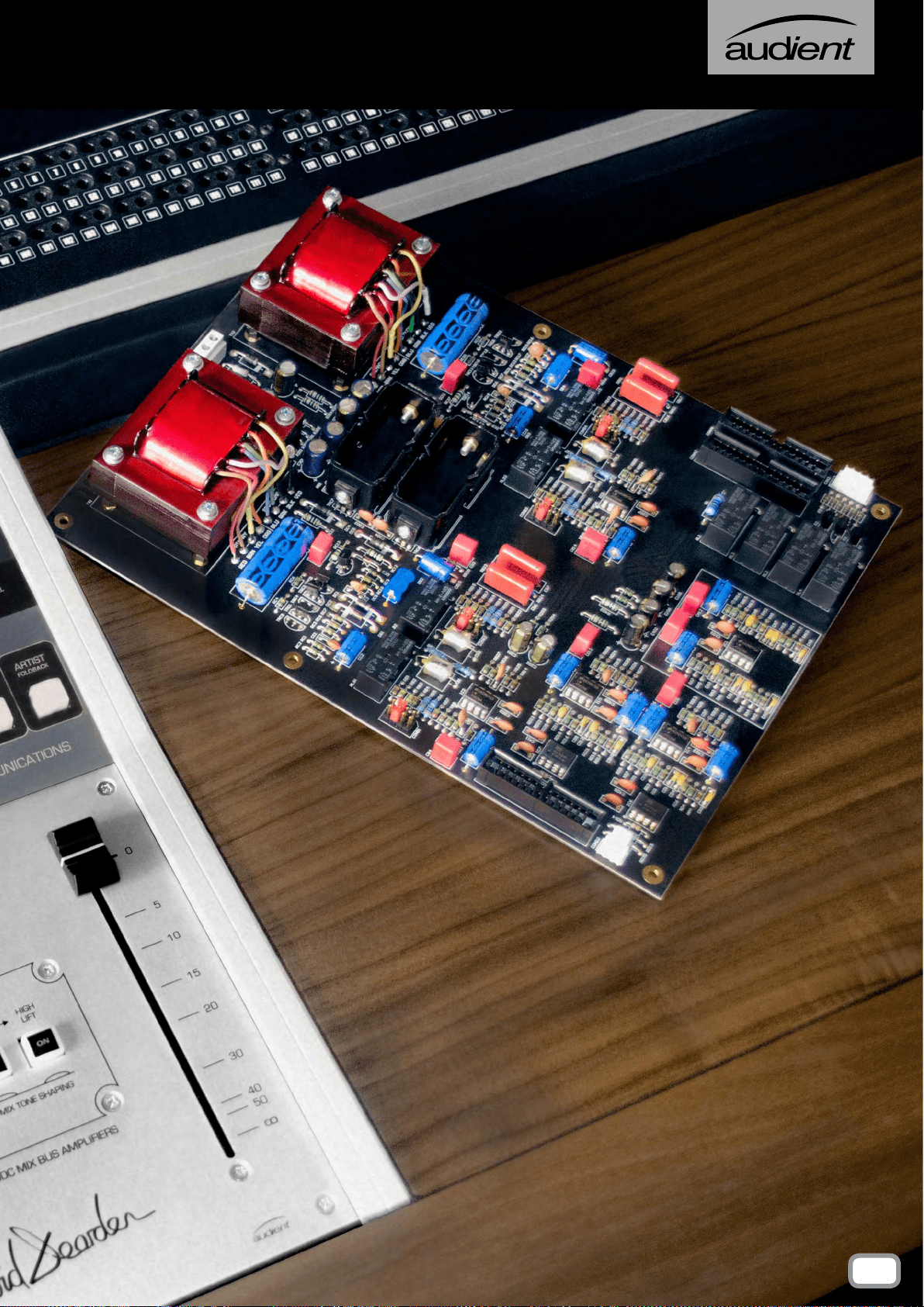
The rst option is RETRO IRON, which runs
the signal through a vintage style amplication
stage followed by a pair of Carnhill Transformers
- adding extra weight and warmth to the output.
The transformers also add body and punch to
the low end and a little bit of top end sparkle.
With the RETRO IRON Card switched in, you
can also switch in two Baxandall EQ stages:
Low Bump adds a 2dB boost at 60Hz, this
helps push kick drums and bass forward in the
mix and tightens the low end. High Lift adds a
2dB boost at 20kHz which will make cymbals
sparkle and make vocals more present.
The Mix Bus Insert is located after the Heritage
Output Card and allows you to apply outboard
effects to the entire mix. Plug your outboard
gear into the two mix inserts, one for the left
channel, and one for the right. We recommend
using stereo or stereo linked units, or two
identical units with switched controls. Two
units with continuous controls can be used,
however care must be taken to match the units
to prevent imbalance across the stereo eld.
ADDING MIX BUS COMPRESSION
After the insert is the Mix Bus Compressor, a
Soft Knee VCA compressor, optimised for Mix
Bus use. To insert the compressor into the Mix
bus simply press the IN button.
The Threshold controls at which amplitude the
Compressor begins to compress the signal.
As it is reduced, more of the signal will be
compressed. The Ratio controls by how much
the signal above the threshold is reduced. A
ratio of 2:1 reduces the level by a factor of two,
a ratio of 4:1 reduces the level by a factor of 4
etc.
The Attack and Release controls can be used to
further affect the way the mix is compressed.
The attack controls how quickly the
Compressor reacts when the signal amplitude
moves above the threshold. A slow setting will
result in fast transient signals being compressed
less, and a faster setting means transients will
be compressed with the rest of the signal. The
release controls how quickly the Compressor
stops affecting the signal once it falls below the
threshold level.
The Mix Bus Compressor features a further
feature, labeled Bass Expand. This adds a 350Hz
high-pass lter to the sidechain, which means
low frequencies won’t cause the Compressor
to activate. This can help to give a more full,
consistent low-end.
As the signal is compressed, the overall level
will be reduced, especially when compressing
harshly. To bring the signal back up to its original
level, use the Make-up Gain Knob. Switching
the Compressor in and out and listening for a
volume difference or using the Master Meters
allows you to quickly set you make up gain.
CAPTURING YOUR FINAL MIX
Once you are happy with the mix, it can be
captured by connecting one of the Mix Outputs
to your DAW or another recording medium, and
recording the track in its entirety through the
desk. Riding faders, or altering settings during
mixdown provides the analogue equivalent
of DAW automation, while giving a human
element to a mix.
37
Using asp8024-HE


This part of the manual looks in detail at the optional extras and
modules that you might have included when configuring your
console.
OPTIONAL EXTRAS
AND MODULES
PART III
This section of the manual explains the functionality of the
optional Patchbay Module and how it relates to the features
explained previously in the manual.
PATCHBAY
40
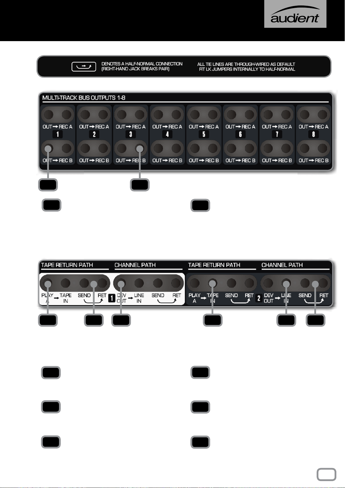
OUT
This is the signal from the Multi-track Bus
Outputs. This is available for each Multi-track
Bus from 1 to 24.
REC A, B
These are the outputs to the 24 track recording
medium, be that a DAW or a tape machine. Each
Multi-track Bus has a separate A and B output,
which allows you to simultaneously track to two
separate recording mediums.
TAPE RETURN PATH
The Tape Return path is the signal coming back
from either your DAW or tape machine.
PLAY A
The signal coming directly from the playback
device.
TAPE IN
Where the signal enters the desk ready to be
mixed to the stereo bus.
SEND/RETURN
The sends and returns allow you to insert
outboard gear into the Tape Return path.
CHANNEL PATH
The Channel Path, is the signal coming from the
microphones and instruments into the desk.
DEV OUT
Stands for device out and allows you to route the
signal directly from the Mic or Line Input.
LINE IN
Where the signal enters the desk to the Line
Inputs for either tracking or mixing.
SEND/RET
The Sends and returns allow you to insert
outboard gear into the Mic/Line Input.
1 2
1
2
3 45 6 7 8
3
4
5
6
7
8
41
patchbay
SUB GROUP INSERTS AND OUTPUTS
SEND/RET
Each Sub Group has its own insert point allowing
you to send the Sub Group signal to outboard gear.
OUT
The output of the Sub Group can be found
here, allowing you to send the Sub Group signal
anywhere on the Patchbay.
DEV
This output sends signal to whatever device is
connected to the Sub Group outputs. If nothing
is plugged into the ‘OUT’ jack, this is where the
Sub Group is sent to.
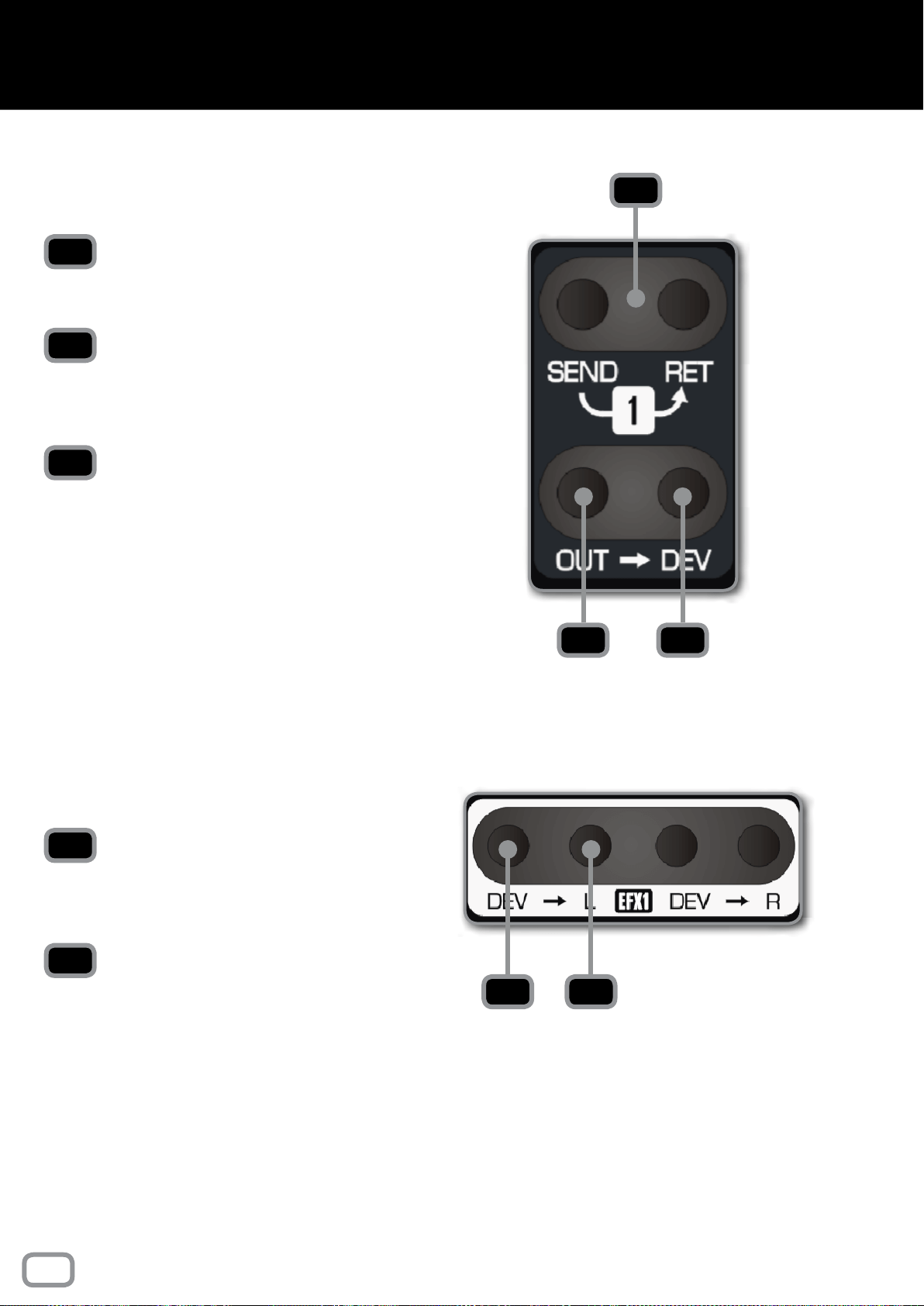
STEREO EFFECTS INPUTS
DEV
This is the signal directly from the device plugged
into the Stereo Effects jack on the rear of the
console.
L, R
Left and right inputs for the Stereo Effects Input.
1
2
3
4
5
1
2 3
4
5
42
patch bay
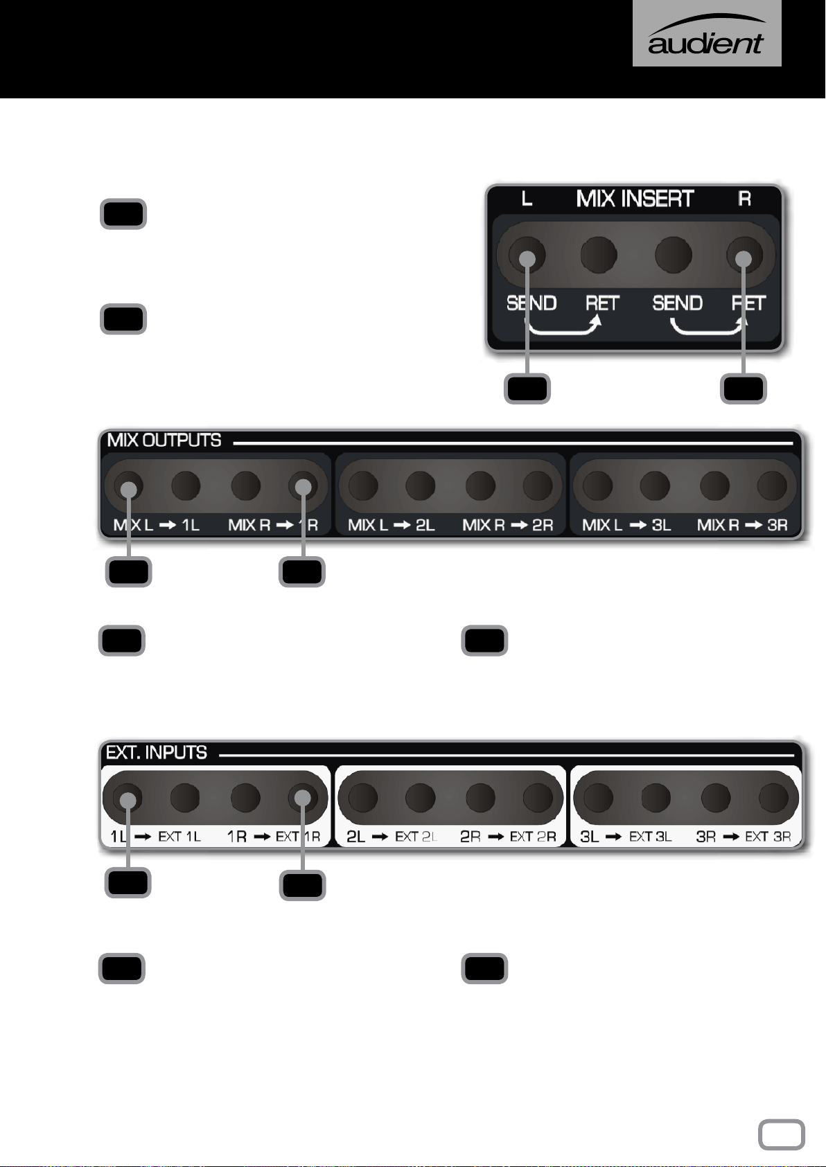
MAIN MIX INSERTS
SEND
The sends are found after the Heritage Card in
the signal chain, so if RETRO IRON is engaged,
it will be present on the sent signal.
RET
The return comes before the Bus Compressor,
so any signal coming into the return will be
compressed if the Compressor is switched in.
MIX L, MIX R
The sends for the left and right sides of the stereo
Mix Bus. This comes after the Master Fader.
1L, 1R, 2L, 2R, 3L, 3R
The left and right outputs of each Mix Output,
labelled accordingly (1L = Mix Output 1, Left
Channel).
1L, 1R, 2L, 2R, 3L, 3R
The left and right inputs of each External Input,
labelled accordingly (1L = External Input 1, Left
Channel). This comes directly from the device
plugged into the External Input connectors on
the rear of the console.
EXT 1L, 1R, 2L, 2R, 3L, 3R
The sends to the Monitor Control Section of
the console. Anything patched in here can be
heard in the Monitor and Foldback Sections of
the console by pressing either EXT 1, 2 or 3.
1
2
1 2
3 4
3 4
5
6
5 6
MIX OUTPUTS
EXTERNAL INPUTS
43
patch bay
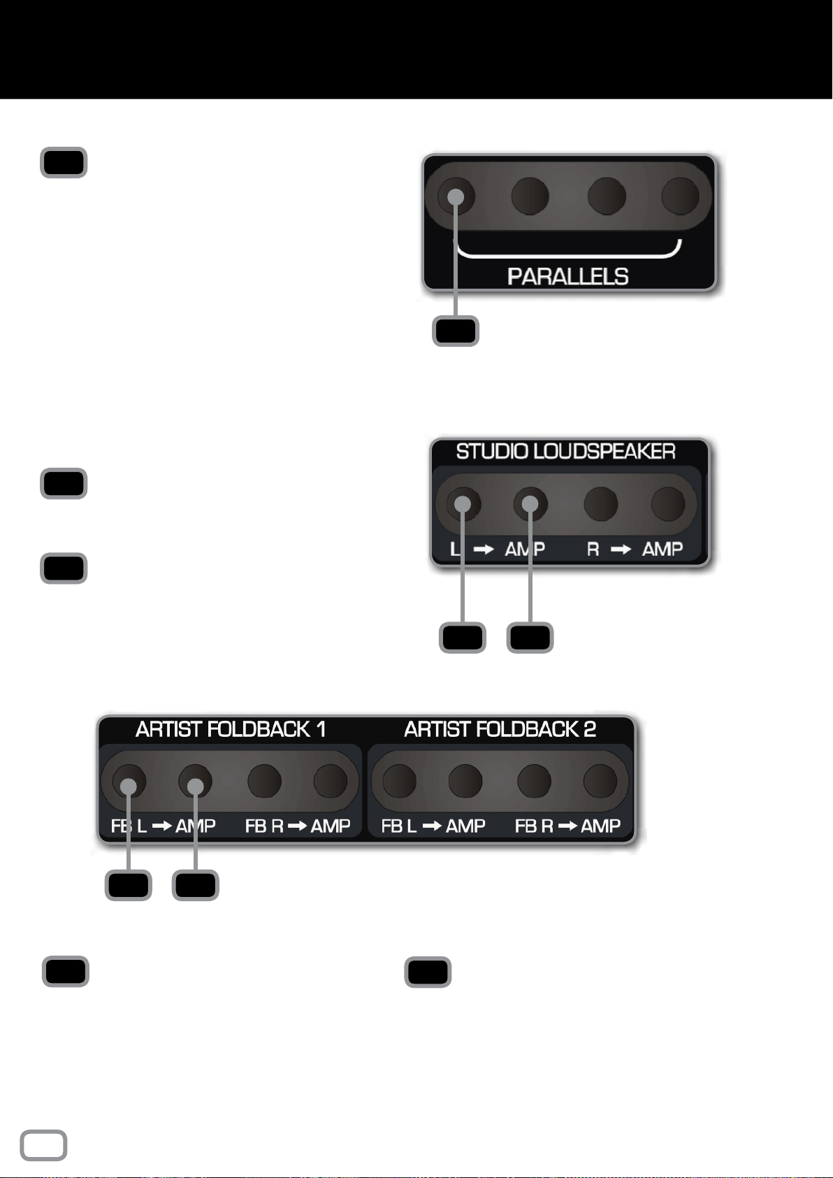
PARALLELS
Any signal patched into one of the Parallel Jacks
will be sent out of the other three jacks allowing
signals to be duplicated. Do not plug in more
than one signal send at the same time as this
will short the outputs together!
STUDIO LOUDSPEAKER
L, R
The left and right channels of the Studio
Loudspeaker send.
AMP
A direct output to any equipment connected to
the Studio Loudspeaker connector on the rear
of the console. In most cases this will be an
amplier for the speaker itself.
FB L, FB R
The left and right channels of each Foldback
Send.
AMP
A direct output to the device connected to the
Foldback connectors on the rear of the console.
In most cases this will be a line level headphone
amplier.
1
1
2
3
2 3
4
5
4 5
ARTIST FOLDBACK 1, 2
44
patch bay
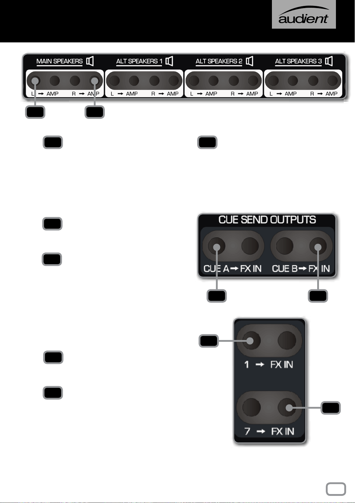
L, R
Contains the signal for the left and right channels
of the Speaker Outputs.
AMP
A direct output to any equipment connected
to the Speaker Connectors on the rear of the
console. In most cases this will be an amplier,
either a stand alone unit or built into a pair of
active monitors.
CUE SEND OUTPUTS
CUE A, B
The signals from the two Cue Mixes. The send
output is after the Cue Master Trim.
FX IN
Patches directly to the device plugged into the
Cue Outputs on the rear of the console.
AUX SEND OUTPUTS
1, 2, 3, 4..... ETC
The outputs from the 12 Aux Sends found on
each channel of the desk.
FX IN
Patches directly to the device plugged into the
Aux Outputs on the rear of the console.
1 2
1 2
3
4
5
6
3 4
5
6
SPEAKER OUTPUTS
45
patch bay
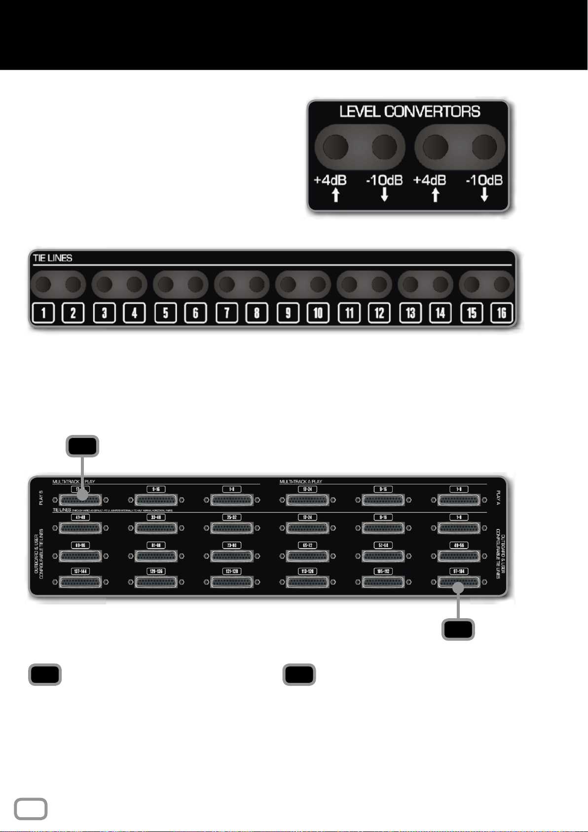
LEVEL CONVERTERS
The level converters take a professional +4dB
signal and passively convert it to -10dB for
patching in consumer level devices. Please note
that the conversion can only bring the signal level
down and can’t be used in reverse.
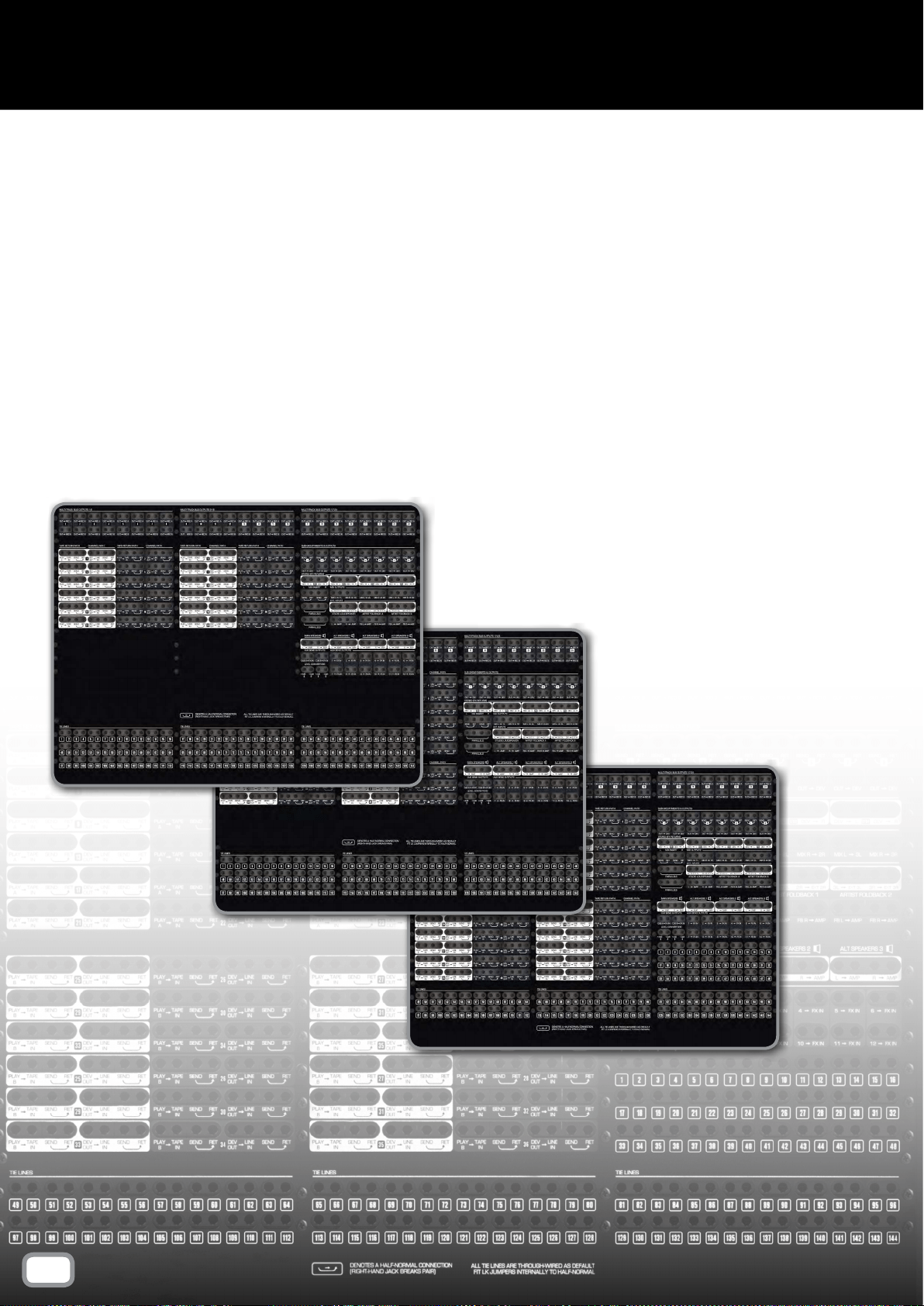
TIE LINES
There are 144 Tie Lines giving plenty of space
to add outboard gear. All Tie Lines are through
wired but can be half normalled in pairs by tting
internal link jumpers.
MULTI-TRACK PLAY A, B
The Multi-track Outputs on a Patchbay console
are found here. The 24 channels are carried on
3 DB25 cables, each carrying 8 channels using
the Tascam standard wiring. There are outputs
for both Multi-track A and B.
TIE LINES
The Tie Lines are accessed through the 18
DB25 connectors on the Patchbay connector
panel. Each Tie Line can act as either an input
or an output depending on how you have them
congured.
1
2
1 2
REAR CONNECTOR PANEL
46
patch bay
For those who have the Dual Layer Control Module, there is a
separate manual section which can be found at the end of this
manual.
47
dlc module
The Producer’s Desk provides extra real estate on your console,
letting you place a keyboard, mouse or even a control surface at
the centre of your console or off to one side for an assistant.
Traditionally the producer would sit at the PD to take session
notes or annotate music scores alongside the engineer. There
are many ways to utilise the PD option, make it work for you and
take advantage of the beautifully included walnut script tray.
If you have two PD modules side-by-side (what we call a Double
PD) it allows you to cater for larger control surfaces such as the
Slate Raven or Avid S3 controller.
48
producer's desk
The 48-Bus Mod provides an extra set of Multi-track Bus Outputs,
forming Multi-track Buses 25-48. Where the rst 24 channels of
the console have access to buses 1-24, and subsequent channels
have access to 25-48. Buses 25-48 do not have access to bus
master trims and so exit the console at unity gain. It is also worth
noting that the Stereo EFX Inputs are only routable to buses 1-24.
With the Bus Mod installed, the console can be operated in two
modes, Bus Split and Bus Link:
In Bus Split mode, channels 1-24 can access Multi-track buses
1-24, whilst channels 25+ can access 25-48, providing up to 48
discrete outputs from the console.
In Bus Link mode, the 25-48 combiners are summed into the
original 1-24 Multi-track buses to provide standard 24-bus
operation across the entire console.
When no Bus Mod option is installed, the Bus Link switch
becomes a handy DFA button for those all important production
decisions...
49
48 BUs mod & DFA
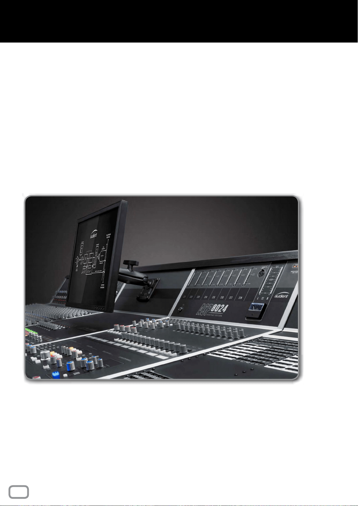
The VESA screen mount provides both 75 and 100mm mounting
options for TFT screens up to 19”.
Simply screw the VESA mount onto the back of the screen using
the four screws provided, then re-attach the system to the ball
joint on the console, making sure it is tightly xed.
To adjust, slightly loosen the clamp and set the ideal position
before tightening it again.
50
Vesa screen mount
The Cable Entry Meter Pod allows you to feed cables through
the console offering a much neater console surface.
To wire cables through the console:
1. Unscrew a rectangular blanking panel found underneath the
console.
2. Carefully unscrew and lower the rear connector panel, making
sure to remove the cable hooks as well.
3. Remove the screws underneath the top wooden trim, accessed
from within the rear of the console.
4. Remove both the horizontal and vertical metal trims on the
console bucket containing the Cable Entry Meter Pod.
5. Tilt the Meter Pod forward and feed the cable towards the
empty blanking panel.
51
cable entry meter pod
For those with an ASP510 Surround Controller, it is possible
to integrate the console Solo and Dim functions, triggering the
appropriate behaviour on the controller.
Pressing a Solo on the console will switch the input of the ASP510
to the Control Room Output of the ASP8024-HE console. A guide
track can be fed to the ASP510 via console Auxes 7-8, and monitored
using the Guide On button on the ASP510.
The ASP510 link is made using a DB25 connection found on the
rear of the console, near the Multi-track Bus connections (exact
positioning changes depending on individual console congurations).
The pin connections are made as follows:
Signal Number Console Interface
1 Control Room Input Left
2 Control Room Input Right
3 Guide Track Input Left
4 Guide Track Input Right
5 Remote Dim Sense
6 Remote Solo Sense
NOTE This link uses a male to female DB25 cable.
52
ASP510 Mod
This part of the manual gives further information about the
console, including warranty, registration, specifications, and
manual glossary
FURTHER
INFORMATION
PART Iv
Your ASP8024-HE Console comes with a manufacturers warranty
of one year from the date of despatch to the end user.
The warranty only covers faults due to defective materials used
in manufacture and faulty workmanship.
During this warranty period Audient will repair or, at its discretion,
replace the faulty part.
We will not provide warranty repair if in our opinion the fault has
resulted from unauthorised modication, misuse, negligence, act
of God, or accident.
We accept a liability to repair your ASP8024-HE as described
above. We do not accept any additional liability.
This warranty does not affect any legal rights you may have against
the person who supplied this product – it is additional to those
rights.
54
warranty
Please register your console on our website to receive useful
information about ASP8024 Heritage Edition including educational
resources, usage tips and more.
Registration is also useful for us to be able to identify your product,
and increase the speed at which we are able to provide technical
support.
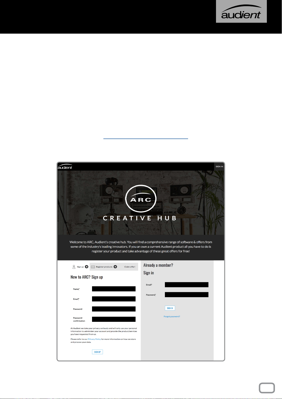
https://arc.audient.com/
55
Registration
*All trademarks are recognized as property of their respective owners

FREQUENCY RESPONSE
Mic Input to Mix Output ±0.3dB (20Hz to 20kHz with 6 to 40dB gain)
Line Input to Mix Output ±0.3dB (20Hz to 20kHz with 0dB gain)
THD + N
Mic XLR Input to any Output < 0.005% @ 1kHz, +22dBu Output
Line Input to any Output < 0.005% @ 1kHz, +22dBu Output
Tape Input to any Output < 0.003% @ 1kHz, +22dBu Output
NOISE
Mic EIN (20-20kHz, 150Ω source) < -127.5dBu
Bus Noise (No Inputs Routed) < -93dBu
Bus Noise (36 Inputs Routed) < -81dBu (990C Mix Amps)
CROSSTALK & MUTE ATTENUATION
Short Fader Mute > 90dB @ 1kHz
Long Fader Mute > 90dB @ 1kHz
Mix Assign > 90dB @ 1kHz
Bus Assign > 90dB @ 1kHz
MIC CMRR
Min Gain (6dB) 70dB
Max Gain (66dB) 75dB
MAXIMUM INPUT LEVEL
Mic > +21 dBu (Min Gain)
Line > +30 dBu (Min Gain)
Insert Returns > +21 dBu
MAXIMUM OUTPUT LEVEL
Mix Output > +26dBu into 2kΩ
Bus Output > +26dBu into 2kΩ
Aux Output > +26dBu into 2kΩ
Insert Send > +20dBu into 2kΩ
Monitor, Studio & F/B Outputs > +20dBu into 2kΩ
56
CONSOLE Specifications
57

FREQUENCY RESPONSE
RETRO IRON Engaged on Main Mix ±0.1dB (10Hz to 80kHz)
HARD-WIRE BYPASS Relay Switched - No Loading Effects
THD + N
0dBu into 600Ω < 0.016% @ 1kHz (2nd & 3rd)
+24dBu into 600Ω < 0.033% @ 1kHz
NOISE
RETRO IRON On, EQ Off < -92dBu (20Hz to 20kHz unweighted)
MAXIMUM OUTPUT LEVEL
Carnhill Line Driver +28dBu into 600Ω
Insertion Loss 1dB into 600Ω (Transformer Loading)
Output Gain ±0.5dB Load Dependant
Output Impedance 600Ω
DYNAMIC RANGE 120dB
CROSSTALK < -82dB 10Hz to 10kHz, typ. -88dB @ 1kHz
TONE SHAPING EQ
Low Bump +2dB wide bell @ 60Hz, Baxandall Type
High Lift +2dB wide bell @ 20kHz, Baxandall Type
Gain Adjust Jumper Positions +0.5, +1, +2 (default) or +3dB Options
The Heritage Card was designed and built with world class LM4562 operational ampliers (EQ
stages) and a discrete Class-AB RETRO IRON output stage based upon the best US & UK designs
from the early 1970’s. Taking inuence from two consoles that David Dearden modied and
serviced at Advision Studios in London during his arrival as in-house technician, these consoles
became part of the sound of recording for clients such as David Bowie, Emerson Lake & Palmer,
Shirley Bassey, Fleetwood Mac and many others. The H.E Card offers glue, 3-dimensional detail
enhancement and lower midrange growl - designed by Tom Waterman and ne tuned by ear to
reect these classic tones.
58
RETRO IRON HERITAGE CARD
59

FREQUENCY RESPONSE
Input to Output, load independent ±0.1dB (20Hz to 20kHz)
THD + N VS LOAD
THD into 600Ω @ 1kHz 0.0013% (0dBu), 0.0009% (+18dBu)
THD into 150Ω @ 1kHz 0.0010% (0dBu), 0.0012% (+18dBu)
THD into 60Ω @ 1kHz 0.0024% (0dBu), 0.0016% (+18dBu)
THD into 32Ω @ 1kHz 0.0040% (0dBu), 0.0077% (+17dBu)
NOISE
Reference Headphone Stage < -104dBu (20Hz to 20kHz unweighted)
MAXIMUM OUTPUT LEVEL
Load Dependant +22dBu, typically +18dBu into all phones
MAXIMUM OUTPUT POWER
Power into 600Ω +22dBu @ 0.0010% THD = 317mW
Power into 150Ω +21dBu @ 0.0012% THD = 1W
Power into 60Ω +20dBu @ 0.0080% THD = 2W!
Power into 32Ω +17dBu @ 0.0080% THD = 2W!
DYNAMIC RANGE > 122dB
CROSSTALK < -80dB 10Hz to 10kHz, typ. -82dB @ 1kHz
OUTPUT IMPEDANCE < 10Ω DC Coupled
ASP8024 Heritage Edition comes with a high-current reference headphone amplier provided
as the ALT3 monitor output destination. The new design features a 250mA high current output
stage based upon class leading Burr-Brown
TM
and LM4562 high-speed ampliers. The output is
entirely D.C coupled with very low output impedance for all types of headphones and there is
only one main capacitor in the signal path for very low distortion and sonic performance!
60
HEADPHONE AMPLIFIER
61

48V 48 Volt Phantom Power
AFL After Fader Listen
ALT Alternate (speaker)
AUX Auxiliary
BW Bandwidth of EQ (AKA the “Q-value”)
CH FLIP Channel Flip
DAW Digital Audio Workstation
dBFS Decibels relative to digital full scale
dBU Standard unit in audio level measurement
DEST Destination
DEV Device
DFA Does F*** All
DLC Dual Layer Control
EFX External Effects
EXT External
F/B Foldback
FREQ Frequency
GRP Group
HF High Frequency
HMF High Middle Frequency
HPF High Pass Filter
Hz Unit of Frequency (Hertz)
LF Long Fader
LF (EQ) Low Frequency
LMF Low Middle Frequency
MTR FLIP Meter Flip
PFL Pre Fader Listen
Pre Pre Fader
REC Record
RET Return
SEL Select
SF Short Fader
SIP Solo In Place
SLS Studio Loudspeaker
VCA Voltage Controlled Amplier
VESA Video Electronics Standard Association
62
glossary

66
DLC SUMMARY
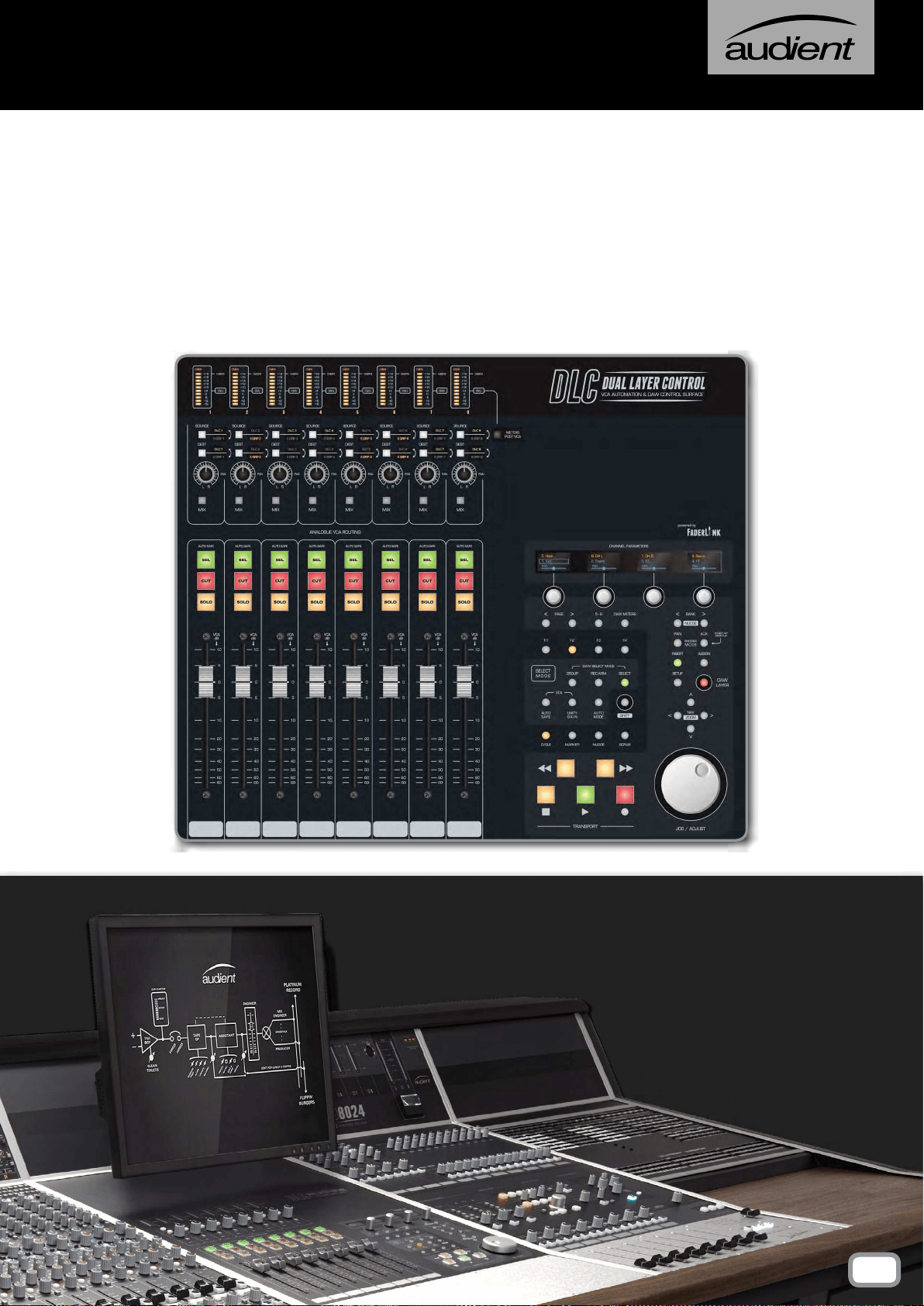
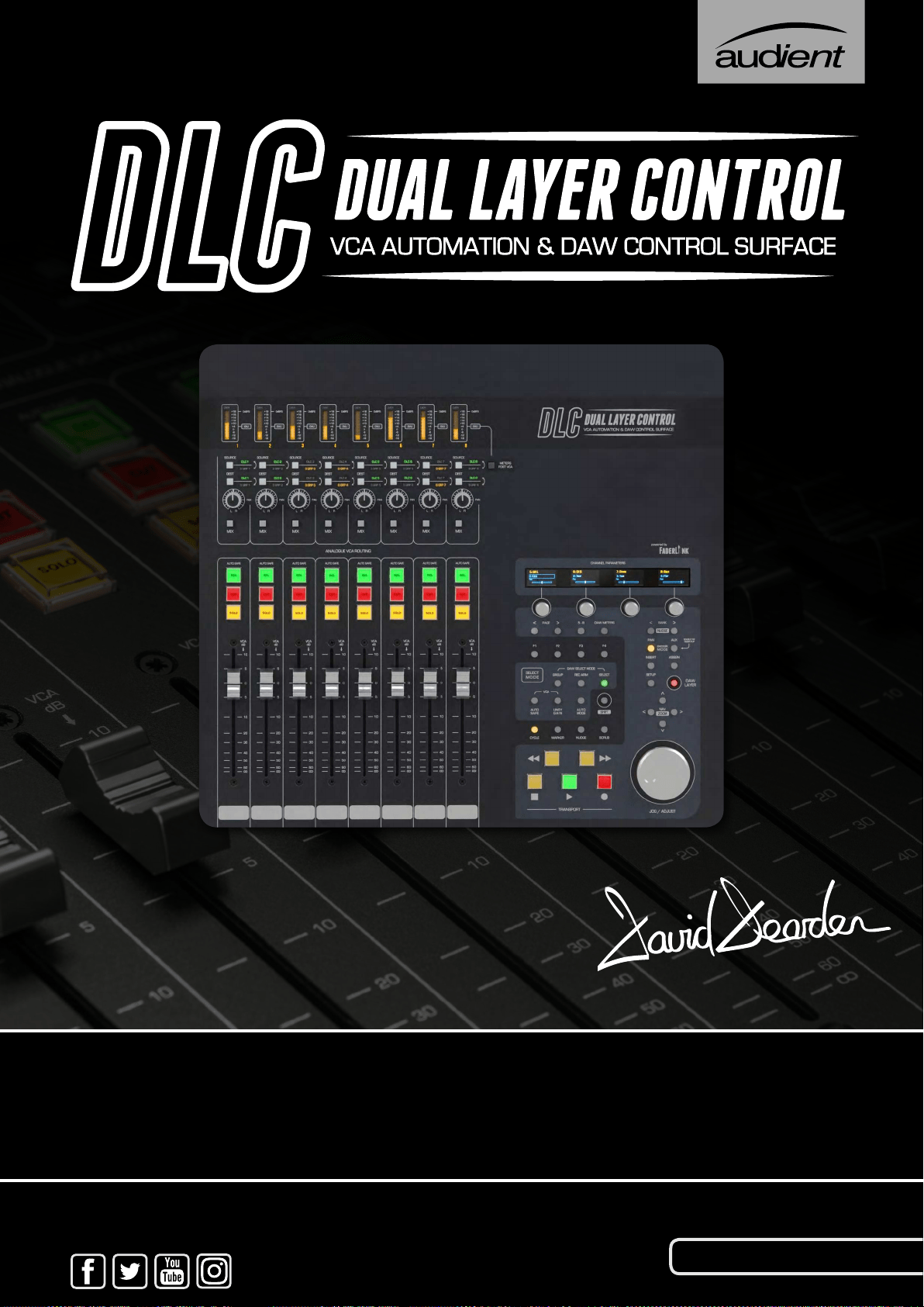
The Dual Layer Control Module gives you control over analogue and
digital worlds from the heart of the console. In the analogue layer, it
provides intuitive analogue automation as well as an extra set of line
inputs and outputs. In the DAW layer, it provides a powerful array of
DAW control features, right at your ngertips. These include eight
bankable faders, transport control, track record enable, pan control,
aux sends, and plug-in manipulation.
The eight channels of analogue VCA automation, let you add movement
and nesse to your console mix balances. The VCAs can be individually
routed to subgroups 1-8 or independent line inputs and outputs, that
can be patched to any insert point on the console for ultimate exibility.
VCA automation is controlled via our proprietary Faderlink plugin (64-
Bit AAX, VST & Audio Unit, supported by all popular DAWs), allowing
you to record, edit and recall eight channels of VCA automation directly
from your DAW session, providing visual representation of volume and
mute alterations.
The DLC has the ability to jump between the analogue and DAW
layers at any time without altering your levels, letting you quickly
adjust settings without interrupting your workow. The DAW layer
is connected via the HUI
TM
protocol and supports: Cubase, Nuendo,
Logic Pro X and Pro Tools.
67
This section goes through the installation process for the DLC
module on your computer, allowing you to make use of the
Analogue Automation and Control Surface functionality.
INSTALLATION
68
Mac installation
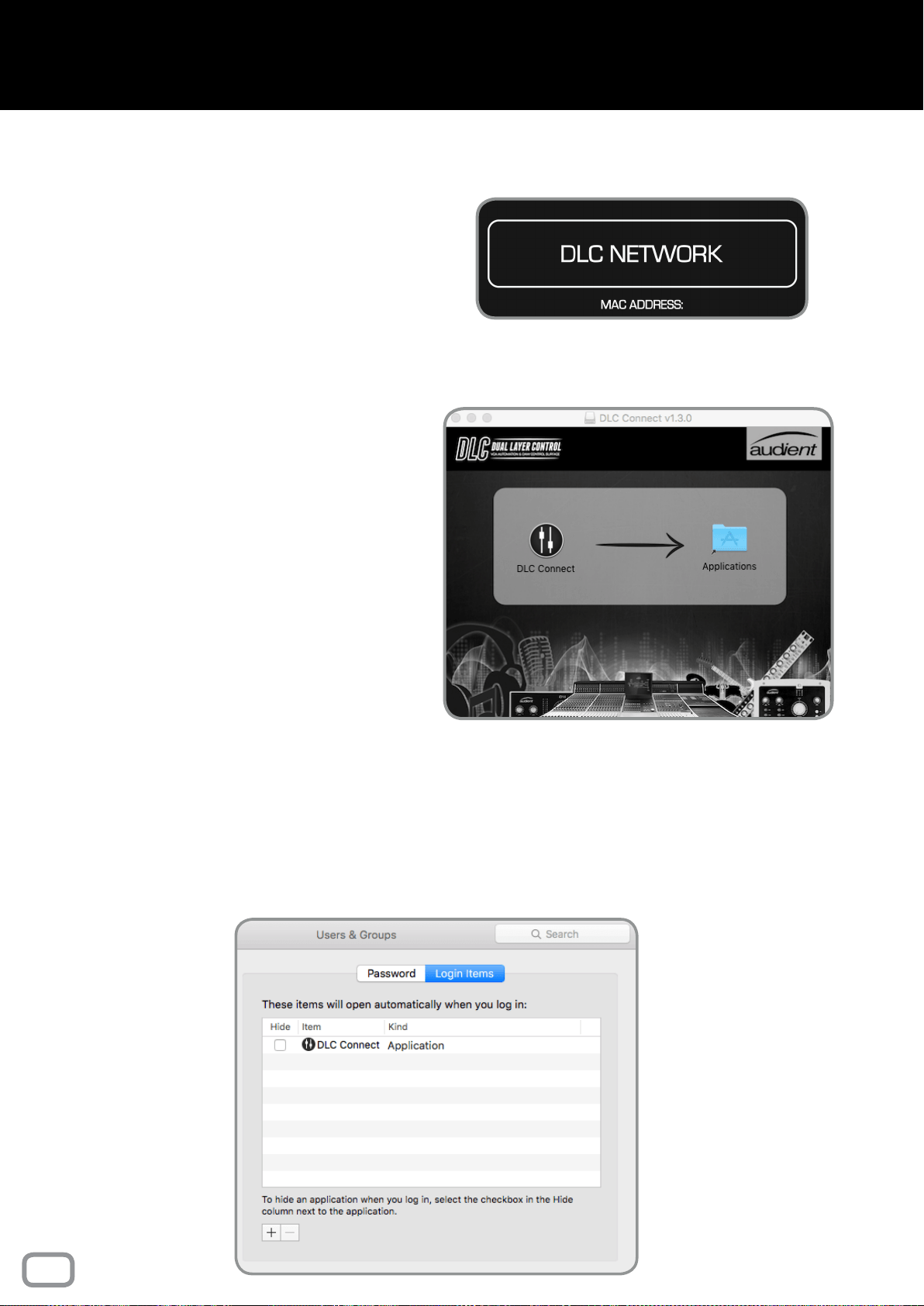
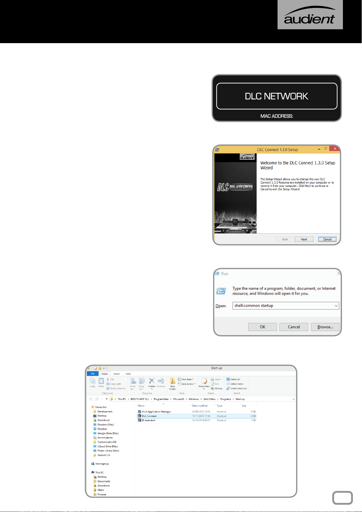
PHYSICAL CONNECTION
To physically connect DLC to your computer,
plug a standard CAT5 Ethernet cable into the
port located above the DLC Network sticker on
the rear of the console, and the other end into
your computer (or router/switch).
DLC CONNECT APP
To achieve communication between DLC and
the Mac, the DLC Connect app is needed. This
creates the necessary MIDI ports for your DAW
to connect to DLC. This app can be downloaded
from our website at:
audient.com/products/consoles/ASP8024-HE/
downloads
Once downloaded, drag the DLC Connect icon
into the Application folder:
Macintosh HD > Applications
It is possible to open the application automatically
on login, making it quicker to get set up each time
the computer is booted up.
Open the app, then right click on the app icon in
the dock, navigate to options, then select Open
at Login.
Alternatively go to: System Preferences >
Accounts > [Account Name] > Login Items Tab >
Add New Applications (+ Button) > Browse and
select DLC connect.
69
MAC Installation
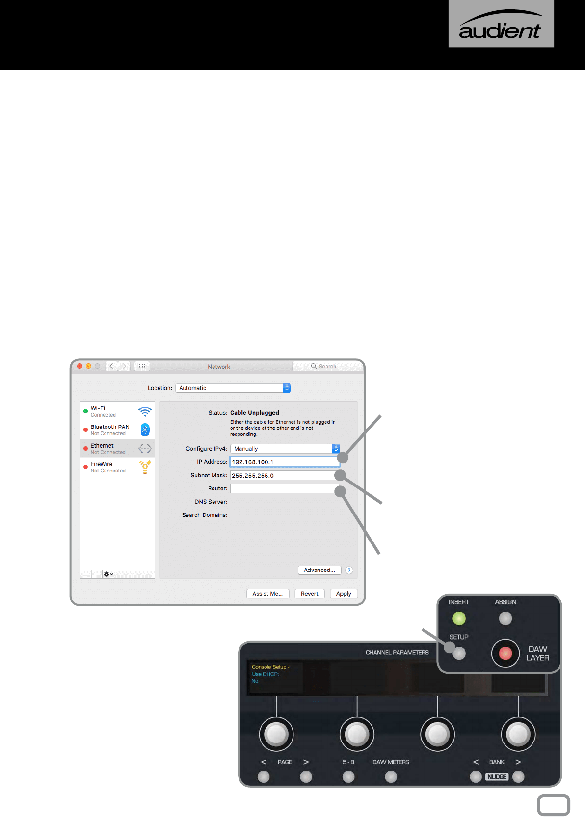
SETTING MANUAL IP ADDRESSES
If you aren’t using DHCP to automatically set IP addresses,
you must set them manually on the DLC and Mac to ensure
the two devices are communicating correctly.
System Preferences > Network > Ethernet Tab > Congure
IPv4 Manually
Example:
Choose a unique IP address
by changing ‘X’ to a number
between 1-254, in the following
IP address:
192 . 168 . 100 . X
This ‘X’ number must be
different on the DLC module
and the computer.
Set the Subnet Mask to
255 . 255 . 255 . 0
We recommend leaving
Router settings blank.
On the DLC Module, press
the Setup Button. The OLED
displays will show the rst page
of the console setup.
Using the Page Keys underneath
the rst encoder, page to the
right and ensure that Use DHCP
is set to
NO in the next menu.
Setup Button
NETWORKING THEORY
On a network, devices must have a unique “address” to ensure they can communicate, this
is known as an IP address. You will need to decide whether your network will automatically
assign IP addresses to connected devices, or if you will manually assign them yourself.
If connecting DLC to your computer directly, you will most likely want to set the IP addresses
manually, however if connecting DLC to a larger network, typically the IP address will be
automatically assigned using “DHCP” (you will commonly have used this when connecting to
things like WiFi networks).
70
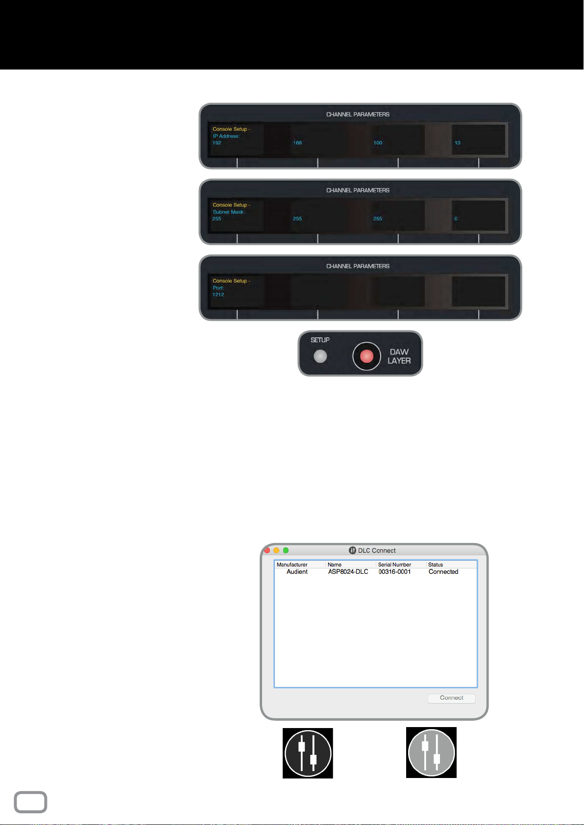
MAC Installation
Page right again to reach the
IP address screen and use the
encoders to set the IP address to:
192 . 168 . 100 . X
(ensuring that ‘X’ is different to
that of the computer).
On the following pages, set the
Subnet Mask to:
255 . 255 . 255 . 0
Then set the Port to:
1212
Press the Setup Button again
to exit setup and save these
settings.
SETTING AUTOMATIC IP ADDRESS (USING DHCP)
If you have connected DLC to a network using DHCP to automatically assign IP addresses,
then you will need to set DLC to use DHCP.
On the second page of the Setup Menu, ensure that the Use DHCP option is set to
YES,
then press the Setup Button again to exit setup and save these settings. Make sure your
Mac is congured to use DHCP in the Network System Preferences (by default your Mac
should be set to use DHCP).
Connected
Disconnected
DLC CONNECT
Once network settings have been nalised,
reboot the console and the computer. On
rebooting, DLC Connect should open and
the console should be listed. Highlight
the console within the app, and click the
connect button.
Your DLC module should now be connected
to your Mac and ready for conguration
as a HUI control surface and analogue
automation platform.
The DLC connect app icon in the menu bar
will display the connectivity status, with
a black icon indicating DLC is connected,
and a greyed out icon indicating DLC is
disconnected.
71
Windows Installation
PHYSICAL CONNECTION
To physically connect DLC to your computer,
plug a standard CAT5 Ethernet cable into the
port located above the DLC Network sticker on
the rear of the console, and the other end into
your computer (or router/switch).
DLC CONNECT APP
To achieve communication between DLC and
the PC, the DLC Connect app is needed. This
creates the necessary MIDI ports for your DAW
to connect to DLC. This can be downloaded from
our website at:
audient.com/products/consoles/ASP8024-HE/
downloads
Once downloaded, double click on the le to
begin the installation process.
To enable the application to boot upon user login:
Find the DLC Connect app in the Start Menu,
right click on it and create a shortcut.
Right click on the shortcut and copy it.
Press Windows Key + R, and type “shell:common
startup”, this will open a folder containing the
startup apps for all users of the computer.
Right click inside the window and paste the DLC
Connect shortcut. DLC Connect will now open
upon user login.
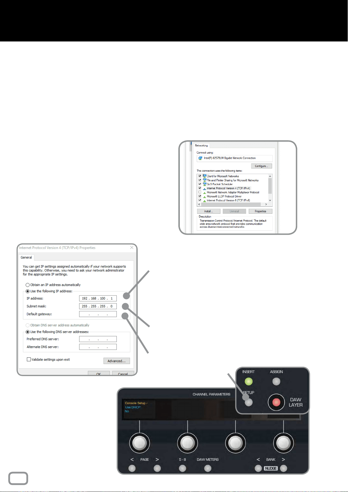
72
Windows Installation
SETTING MANUAL IP ADDRESSES
If you aren’t using DHCP to automatically assign IP
addresses, you must manually set them to ensure the
two devices are networked correctly.
Control Panel > Network and Internet > Network and
Sharing Centre > Change Adapter Settings
In this window, right click on Ethernet and select
Properties. From the list of connections, nd IPv4 and
click properties. Here you can change the IP address.
Example:
Choose a unique IP address by changing ‘X’ to
a number between 1-254, in the following IP
address:
192 . 168 . 100 . X
This ‘X’ number must be different on the DLC
module and the computer.
Set the Subnet Mask to
255 . 255 . 255 . 0
We recommend leaving Default Gateway
settings blank
On the DLC Module, press
the Setup Button. The OLED
displays will show the rst page
of the console setup.
Using the Page Keys underneath
the rst encoder, page to the
right and ensure that Use DHCP
is set to
NO.
Setup Button
NETWORKING THEORY
On a network, devices must have a unique “address” to ensure they can communicate, this
is known as an IP address. You will need to decide whether your network will automatically
assign IP addresses to connected devices, or if you will manually assign them yourself.
If connecting DLC to your computer directly, you will most likely want to set the IP addresses
manually, however if connecting DLC to a larger network, typically the IP address will be
automatically assigned using “DHCP” (you will commonly have used this when connecting to
things like WiFi networks).
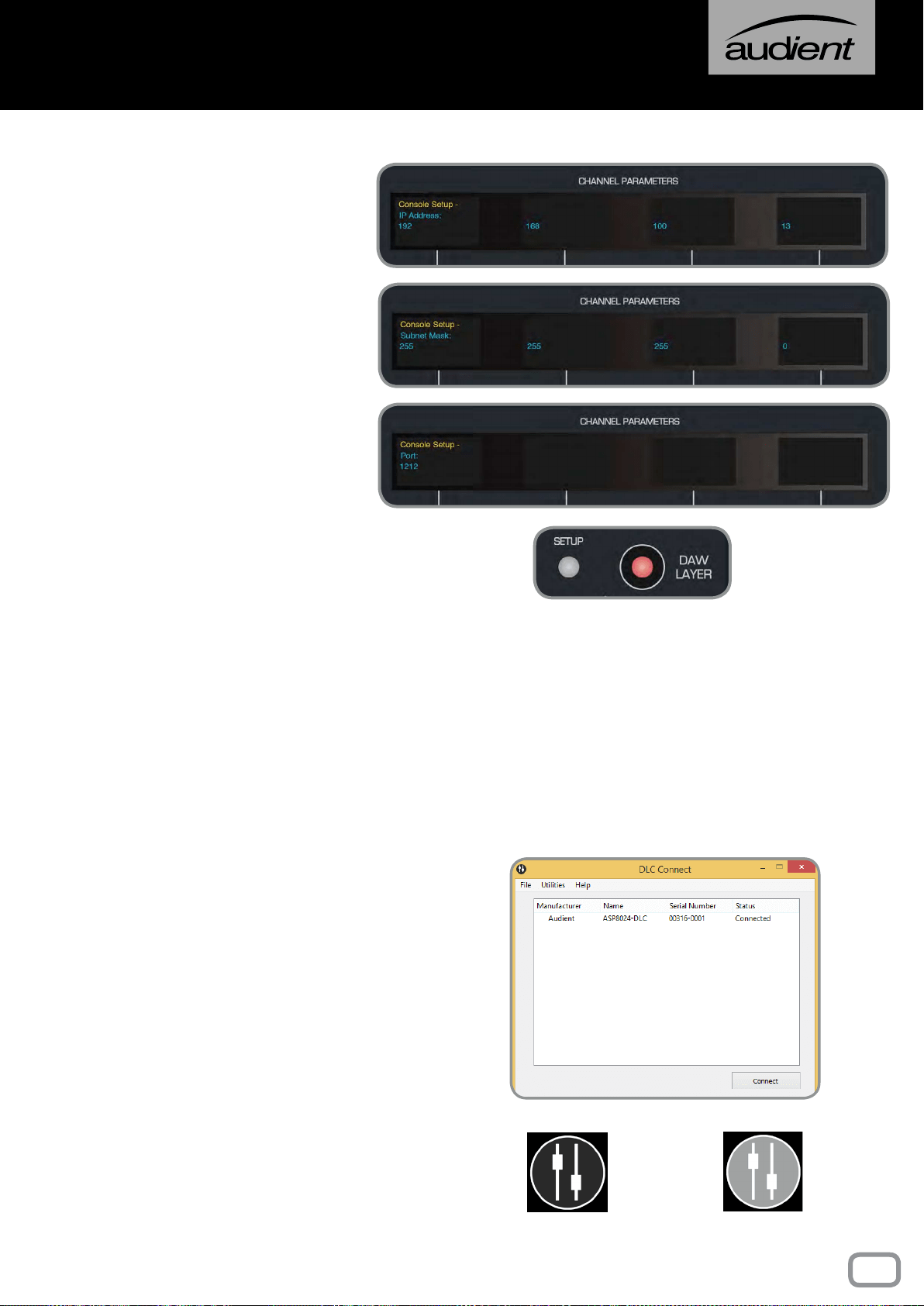
73
Windows Installation
Page right again to reach the
IP address screen and use the
encoders to set the IP address to:
192 . 168 . 100 . X
(ensuring that ‘X’ is different to
that of the computer).
On the following pages, set the
Subnet Mask to:
255 . 255 . 255 . 0
Set the Port to:
1212
Press the Setup Button again to
exit setup and save your settings.
Connected
Disconnected
SETTING AUTOMATIC IP ADDRESS (USING DHCP)
If you have connected DLC to a network using DHCP to automatically assign IP addresses,
then you will need to set DLC to use DHCP.
On the second page of the Setup Menu, ensure that the Use DHCP option is set to
YES,
then press the Setup Button again to exit setup and save these settings. Make sure your
PC is congured to use DHCP in the PC Network settings (by default your PC should be
set to use DHCP).
DLC CONNECT
Once network settings have been nalised,
reboot the console and the computer. On
rebooting, DLC Connect should open and
the console should be listed. Highlight
the console within the app, and click the
connect button.
Your DLC module should now be connected
to your PC and ready for conguration
as a HUI control surface and analogue
automation platform.
The DLC connect app icon in the System
Tray will display the connectivity status,
with a black icon indicating DLC is
connected, and a greyed out icon indicating
DLC is disconnected.
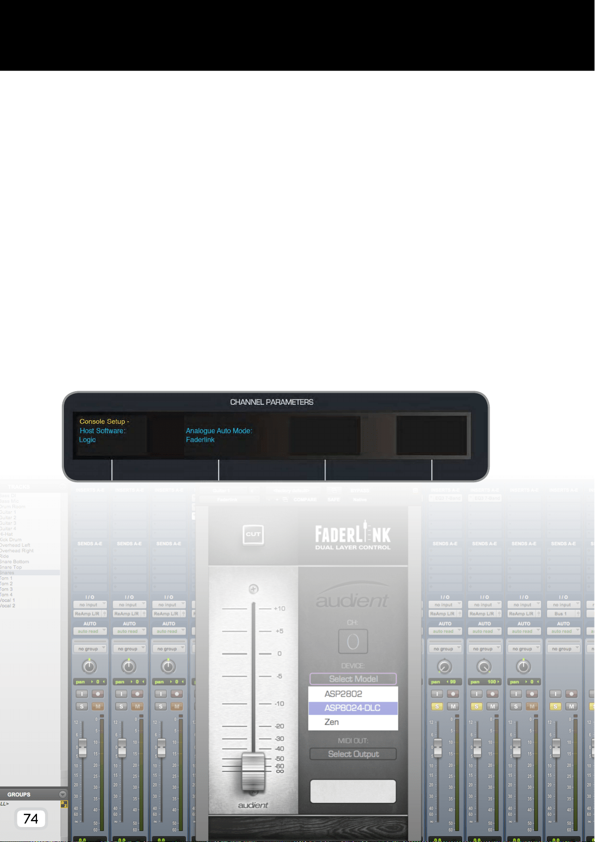
74
Faderlink Installation
Faderlink is a simple and elegant solution to the problem of integrating analogue automation
within Digital Audio Workstation projects, without the need for a dedicated console computer.
Faderlink presents you with a Fader and Cut switch which can be automated in the same way as
any other plugin parameter in your workstation (see page 17).
- Download the Faderlink plugin installer from our website:
audient.com/products/consoles/ASP8024-HE/downloads
- Close your Digital Audio Workstation applications.
- Double click on the downloaded le to open the installer, then follow the instructions.
- Once installed, relaunch your DAW and Faderlink should appear in the list of plugins.
ON THE CONSOLE
The DLC module must have it’s Analogue Automation Mode set to Faderlink. Press the Setup
Button, then use the second encoder to select Faderlink as the Analogue Automation Mode. Press
the Setup Button again to save the settings.
75
This section outlines the different features of the DLC module
and how to use them, as well as how to use the Faderlink Plugin.
DLC OPERATION
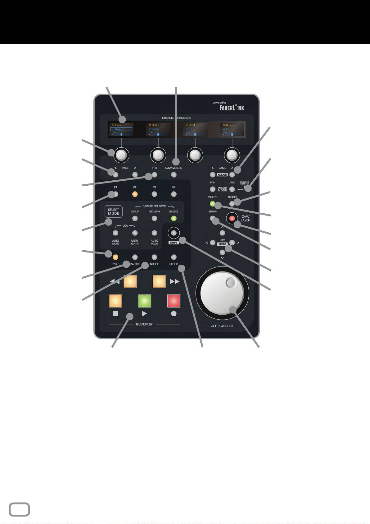
76
Control surface Interface
Channel Encoders
Page Left & Right
Programmable
Function Buttons
Channel Select
Mode
Cycle Toggle for
DAW Looping
Insert DAW
Marker
DAW Nudge
Encoder & Display
Flip for Ch 5-8
Channel Bank
(Nudge with Shift)
Encoder Mode
Insert
Customisation
Multi-Function
Assign Key
Setup Menu
DAW Layer
DAW Navigation
(Zoom with Shift)
Shift
Key
Jog / Shuttle
Wheel
Scrub Button
OLED Channel
Displays
Transport
Panel
DAW
Meters
The control surface functions operate differently depending on
your choice of DAW. For instructions on how to use the control
features within your workstation, please refer to the DAW
specic control surface manuals found online at:
audient.com/products/consoles/ASP8024-HE/downloads
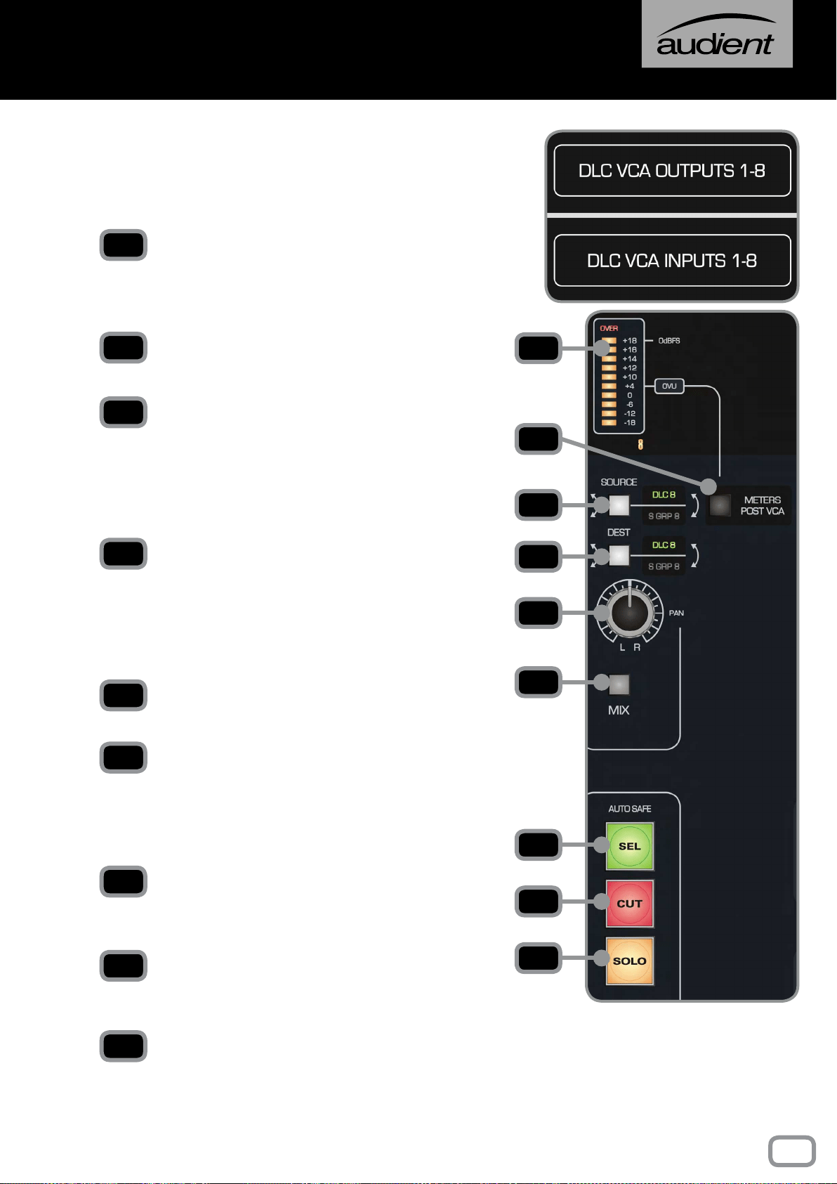
77
Audio routing
DLC has eight line inputs and outputs, labelled the
DLC VCA Inputs/Outputs. These are accessible
on the rear of the console on DB25 connectors
(location depends on console conguration).
METER
Displays the level of the signal coming from the
source, unless the DAW Meters switch on the
control surface is engaged.
METERS POST VCA
Switches the meters between Pre and Post fader.
SOURCE
The audio can be sourced from the DLC VCA Inputs
or the eight Sub Groups on the console. If S GRP
is selected, it breaks the signal to that Sub Group,
unless it is also selected as the destination on that
channel.
DEST
The eight DLC channels can be assigned to the
DLC VCA Outputs or the Sub Groups. If S GRP is
engaged, it will replace all other channels routed
to the Sub Group, unless the Source button is also
set to S GRP.
PAN
Pans the audio in the mix.
MIX
Assign the output of the DLC channel to the Mix
Bus. You can therefore route the line level sources
directly to mix, effectively adding a further eight
channels to the console.
SELECT
Selects the channel, for use with Unity and Auto
Safe Mode, as well as in the DAW Layer.
CUT
Cuts the channel, can be automated in the Analogue
Layer, and used in the DAW Layer.
SOLO
Solos the channel in Analogue and DAW Layers.
This cannot be automated.
1
3
4
5
6
2
To insert the DLC channel
into a Sub Group and
automate it’s volume, ensure
that both the Source and
Destination buttons are
switched to S GRP.
7
8
9
1
2
3
4
5
6
7
8
9
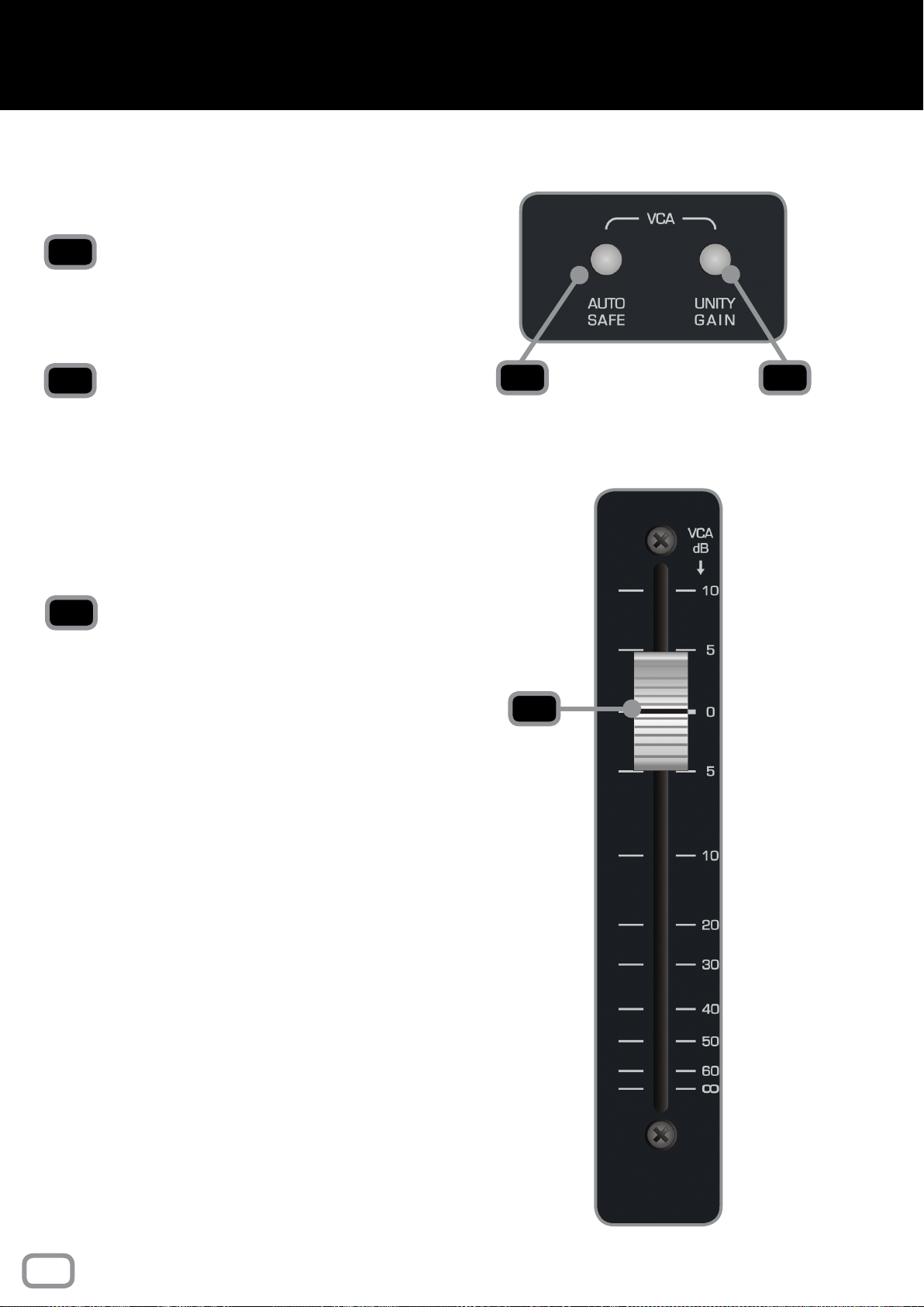
78
VCA Functionality
There are two buttons on the right section of DLC
that are applicable in the Analogue Layer when
using analogue automation.
AUTO SAFE
Press Auto Safe then engage the Select button on
any channel that you want to completely isolate
from automation control. Ideal for trying out a new
ride before recording a pass of automation.
UNITY
Press Unity then engage the select button on any
channel that you want to x at unity gain (0dB).
1 2
1
2
VCA FADER
This fader is not directly in the audio path of the
channel, but rather acts as a control fader, sending
D.C. control voltage changes to the VCAs, which
provides attenuation, mute and +10 dB of gain
“in-hand” above unity for the analogue audio path.
The VCA analogue automation functionality is
particularly useful for automating the volume of a
signal post analogue dynamics processing.
3
3
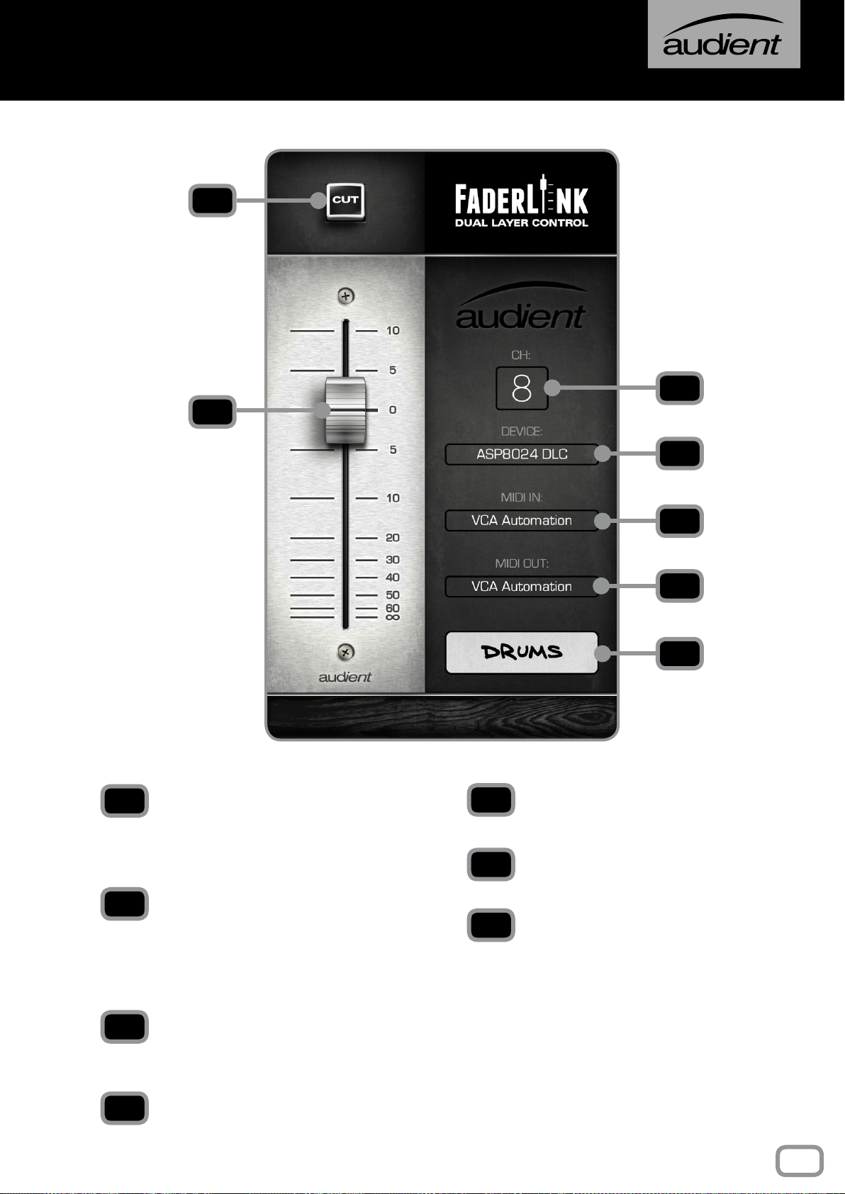
79
Faderlink Interface
1
2
3
4
5
6
7
CHANNEL CUT BUTTON
Cuts the audio for this channel. This mimics the
Cut Button on the selected channel on the DLC
module.
CHANNEL FADER
Controls the volume of the VCA fader, operating
between -inf and +10dB. This fader mimics the
VCA fader on the selected channel on the DLC
module.
CHANNEL SELECTION MENU
Select the DLC channel that you want to save
the channel automation for.
DEVICE MENU
Select the appropriate device from the menu.
1
2
MIDI IN MENU*
Select the MIDI Input for Automation.
MIDI OUT MENU*
Select the MIDI Output for Automation.
SCRIBBLE STRIP
Allows you to name the channel, this will appear
on the corresponding channel on the DLC OLED
displays.
*Set these to ASP8024-DLC Automation.
3
4
5
6
7
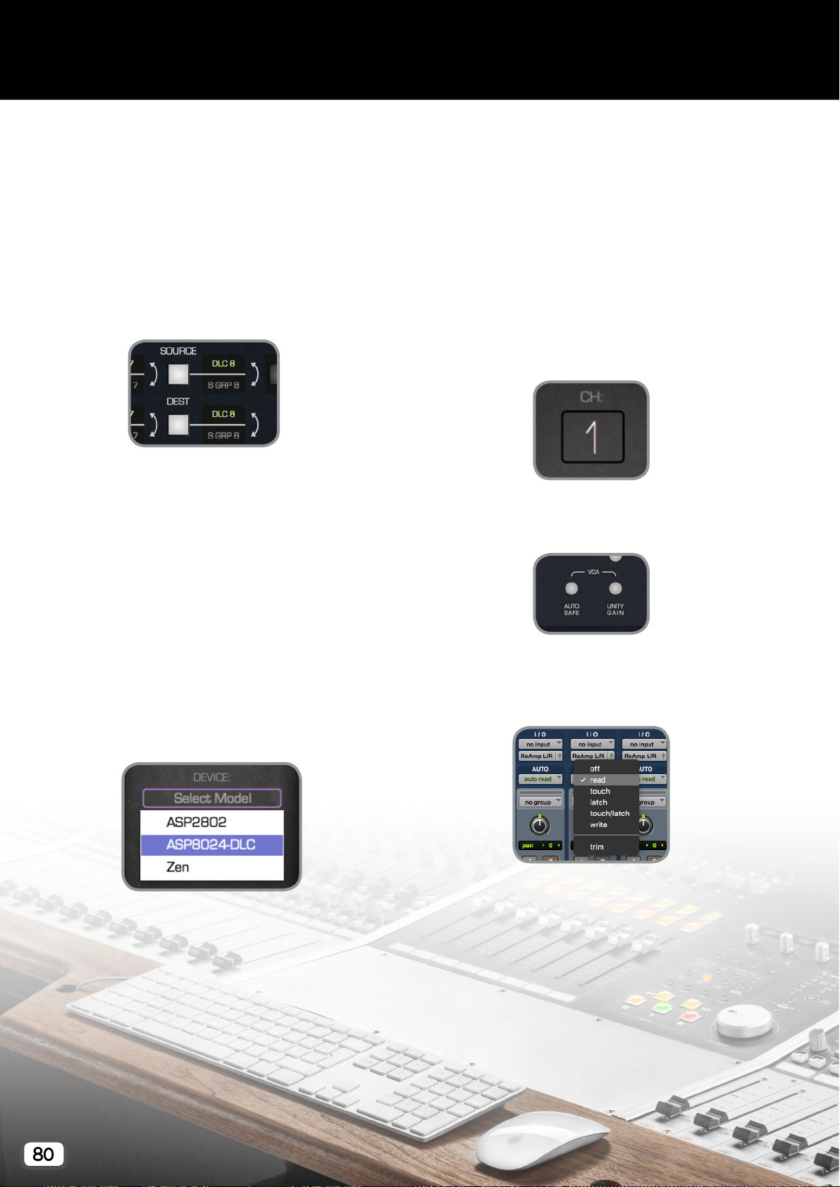
80
Analogue Automation
For analogue automation functionality, first
ensure the DLC has the Analogue Automation
Mode set to Faderlink in the rst page of the
Setup Menu, then follow these instructions for
each DLC channel you want to automate:
1. Set the desired audio routing using the Source
and Dest buttons.
2. In your DAW, add a Faderlink Plugin instance
to any track. This can be a track with or without
regions present. If automating a group from
your DAW or an individual track, it would make
sense to put the Faderlink plugin on those tracks
to keep things organised. Alternatively a single
track could be created with eight instances
of Faderlink, so that all automation data is
contained on the same track.
3. Set the Device to ASP8024-DLC and ensure
that the MIDI In and Out have automatically set
to ASP8024-DLC Automation.
4. Set the channel number to the VCA fader you
want to control on the DLC module, and name
the channel by double clicking on the Scribble
Strip and typing the name.
5. Ensure that Auto Safe and Unity are disengaged
on the channel.
6. For the DAW track that contains the Faderlink
plugin(s), set the automation mode appropriately
(e.g. Touch, Latch or Write).
7. Begin playback and ride the fader (and cut) to
write the automation.
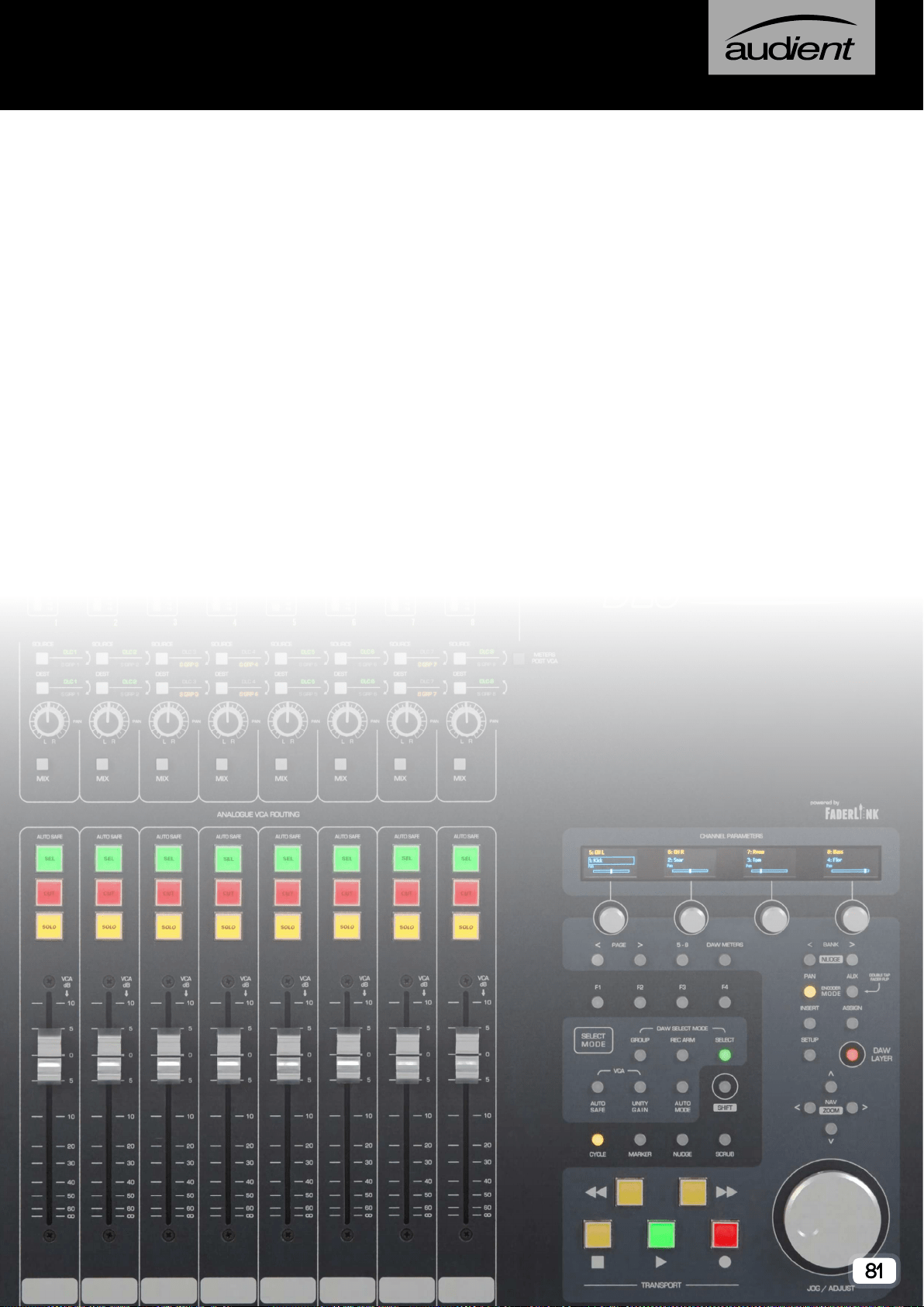
81
Firmware & Support
When updates are released for your console to improve control surface
workow, bug xes and add new features, you may need to update the
console rmware.
Firmware les are packaged as part of the DLC Connect App download,
so download the latest version from our website and follow the simple
instructions provided.
By registering your console, you can be notied via email when new
updates are made available. Please visit the Registration Section of the
main ASP8024-HE manual for more information.
If you are experiencing any issues, please contact our support team via
email at:

Audient Ltd,
Aspect House
Herriard
Hampshire
RG25 2PN
United Kingdom
+44 (0)1256 381944