D R Y E R I N S T A L L A T I O N M A N U A L
DOC. NO. 096008
EDITION 28.2019
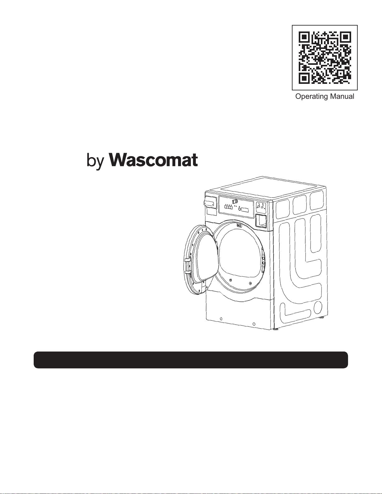
Operating Manual
CROSSOVER SERIES
To reduce the risk of re, electric shock, or injury to persons when using your appliance,
follow basic precautions, including the following:
• Read all instructions before using the appliance.
• Do not dry articles that have been previously cleaned in, washed in, soaked in,
or spotted with gasoline, dry-cleaning solvents, or other ammable or explosive
substances, as they give off vapours that could ignite or explode.
• Do not allow children to play on or in the appliance. Close supervision of children is
necessary when the appliance is used near children.
• Before the appliance is removed from service or discarded, remove the door to the
drying compartment.
• Do not reach into the appliance if the drum is moving.
• Do not install or store this appliance where it will be exposed to the weather.
• Do not tamper with controls.
• Do not repair or replace any part of the appliance or attempt any servicing unless
specically recommended in the user-maintenance instructions or in published user-
repair instructions that you understand and have the skills to carry out.
• Do not use fabric softeners or products to eliminate static unless recommended by the
manufacturer of the fabric softener or product.
• Do not use heat to dry articles containing foam rubber or similarly textured rubber-like
materials.
• Clean lint screen before or after each load.
• Keep area around the exhaust opening and adjacent surrounding areas free from the
accumulation of lint, dust, and dirt.
• The interior of the appliance and exhaust duct should be cleaned periodically by
qualied service personnel.
• Do not place items exposed to cooking oils in your dryer. Items contaminated with
cooking oils may contribute to a chemical reaction that could cause a load to catch re.
• See "Electrical Requirements" located in the Installation Instructions for grounding
instructions.
SAVE THESE INSTRUCTIONS
WARNING
IMPORTANT SAFETY INSTRUCTION
Purchaser and user should consult local gas supplier for proper
instructions to be followed in the event user smells gas.
FIRE OR EXPLOSION HAZARD
• Failure to follow safety warnings exactly could result in serious injury, death or
property damage.
• Do not store or use gasoline or other ammable vapors and liqids in the vicinity
of this or any other appliance.
WHAT TO DO IF YOU SMELL GAS:
• Do not light the gas appliance; Do not touch any electrical switch.
• Do not use any phones in your building.
• Clear the room, building, or area of all occupants.
• Immediately call your gas supplier from a neighbor’s phone. Follow the gas
supplier’s instructions.
• If you cannot reach your gas supplier, call the re department.
• Installation and service must be performed by a qualied installer, service
agency, or gas supplier.
GROUNDING INSTRUCTIONS
This appliance must be connected to a grounded metal, permanent wiring
system, or an equipment-grounding conductor must be run with the circuit
conductors and connected to the equipment-grounding terminal or lead on the
appliance.
FIRE HAZARD:
• Failure to follow safety,warnings exactly could result in serious injury, death or
property damage.
• Do not install a booster fan in the exhaust duct.
• Install all clothes dryers in accordance with the installation instructions of the
manufacturer of the dryer.
Do not store or use gasoline or other ammable vapors and liquids in the vicinity
of this or any other appliance.
WARNING
WARNING
WARNING
FOR YOUR SAFETY

Model Numbers
Electric
DLHF0CEMI
DLHF0CE
DLHS0CEMI
DLHS0CE
DLHF0817EMI
DLHF0817E
DLHS0817EMI
DLHS0817E
Gas
DLHF0817GMI
DLHF0817G
DLHS0817GMI
DLHS0817G
Installation Instructions
Install the clothes dryer according to the manufacturer’s
instructions and local codes.
WARNING: ALL OPERATING AND MAINTENANCE PROCEDURES SHOWN IN THIS
MANUAL MUST BE FOLLOWED AT THE FREQUENCY SPECIFIED FOR PROPER
OPERATION OF YOUR MACHINE.
PLEASE ENTER THE FOLLOWING INFORMATION AS IT APPEARS ON THE
MACHINE(S) DATA PLATE(S).
SAVE THESE INSTRUCTIONS
MACHINE MODEL
MACHINE TYPE (GAS / ELECTRIC)
MACHINE SERIAL NUMBER
Risk of Fire
• Clothes dryer installation must be performed by a qualied installer
• Do not install a clothes dryer with exible plastic venting materials. If exible
metal (foil type) duct is installed, it must be of a specic type identied by
the appliance manufacture as suitable for use with clothes dryers. Flexible
venting materials are known to collapse, be easily crushed, and trap lint. These
conditions will obstruct clothes fryer airow and increase the risk of re.
• To reduce the risk of severe injury or death, follow all installation instructions.
WARNING

NOTICE TO: OWNERS, OPERATORS AND DEALERS
IMPROPER INSTALLATION AND INADEQUATE MAINTENANCE, POOR HOUSEKEEPING
AND WILLFUL NEGLECT OR BYPASSING OF SAFETY DEVICES MAY RESULT IN SERIOUS
ACCIDENTS OR INJURY. TO ASSURE THE SAFETY OF CUSTOMERS AND/OR OPERATORS
OF YOUR MACHINE, THE FOLLOWING MAINTENANCE CHECKS MUST BE PERFORMED ON
A DAILY BASIS.
1. Prior to operation of the machine, check to make certain that all operating instructions and
warning signs are afxed to the machine and legible. (See the following page of this manual for
description and location of the signs). Missing or illegible ones must be replaced immediately.
Be sure you have spare signs and labels available at all times. These can be obtained from
your distributor or from Laundrylux.
2. CLOSE THE DOOR and start machine. While operating open the door. The machine must stop.
If the machine fails to stop, disconnect power and arrange for service.
3. DO NOT UNDER ANY CIRCUMSTANCES ATTEMPT TO BYPASS OR REWIRE ANY OF THE
MACHINE SAFETY DEVICES AS THIS CAN RESULT IN SERIOUS ACCIDENTS.
4. Be sure to keep the machine(s) in proper working order. Follow all maintenance and safety
procedures.
5. Further information regarding machine safety, service and parts can be obtained from your
dealer or from Laundrylux through its Technical Care Department - (516) 371-0700.
All requests for assistance must include the model, serial number and electrical characteristics
as they appear on the machine identication plate. Insert this information in the space provided
on earlier page of the manual.
6. WARNING: DO NOT OPERATE MACHINE(S) WITH SAFETY DEVICES BYPASSED,
REWIRED OR INOPERATIVE!
7. Failure to properly ground the dryer may result in hazardous conditions and will void the
warranty.
MANUFACTURED BY HAIER EXCLUSIVELY FOR LAUNDRYLUX

NOTICE TO INSTALLER
Improper installation of this machine:
• May cause serious damage to the machine.
• May result in other property damage.
• May cause personal injury.
• Will void the manufacturer’s warranty.
Location Requirements
• The dryer must be installed on a sound level oor capable of supporting its weight. Carpeting must
be removed from the oor area that the dryer is to rest on.
• The dryer must be installed with adequate clearance for air openings in the cabinet.
• The dryer must be installed or stored in an area where it will not be exposed to water and/or
weather.
• Dryers installed in residential garages must be elevated 18-inches (45.72 cm) above the oor.
IMPORTANT
• The dryer should be located where a minimum amount of exhaust ducting will be necessary.
• The dryer must be installed in a location/ environment, which the ambient temperature remains
between 40° F (4° C) and 130° F (54° C).
Additional Requirements
• Do not use an extension cord with this appliance. It must be plugged directly into a grounded
electrical outlet.

Contents
Technical Data / Specications ........................................................................1:1
Installation
........................................................................................................2:1
Installation Procedures
...............................................................................2:1
Location Requirements
...............................................................................2:1
Unpacking / Setting Up
............................................................................... 2:1
Enclosure Requirements
............................................................................2:2
Stand Alone / Washer-Dryer Stack / Dryer-Dryer Stack Installation...........2:2
Fresh Air Supply
.........................................................................................2:3
Exhaust Requirements
...............................................................................2:3
Outside Ductwork Protection
...................................................................... 2:4
Venting (Single / Horizontal / Vertical and Multiple)
....................................2:4
Electrical Requirements
..............................................................................2:6
Gas Information
..........................................................................................2:8
Piping
..........................................................................................................2:8
Fuel Conversion
..........................................................................................2:10
Gas Pressure Adjustment
........................................................................... 2:11
Gas Pressure Testing
.................................................................................2:11
Preoperational Instructions
...............................................................................3:1
Shutdown Instructions
......................................................................................4:1
Coin Meter Installation and Blocking Plate
.......................................................5:1
Preventive Maintenance
...................................................................................6:1

Technical Data / Specs
1:1
MAXIMUM CAPACITY (DRY) 22 lb 10 kg
TUMBLER DIAMETER 26 in 66 cm
TUMBLER DEPTH 20.8 in 53 cm
TUMBLER VOLUME 7.7 cu ft 0.22 cu m
TUMBLER/DRIVE MOTOR 1/3 hp 0.25 kW
BLOWER/FAN MOTOR
BLOWER DRIVEN BY
TUMBLER MOTOR
DOOR OPENING (DIAMETER) 22.44 in 57 cm
DOOR SILL HEIGHT 12.6 in 32 cm
GAS MACHINE
VOLTAGE AVAILABLE 120/240V 1ø 60 Hz
APPROXIMATE NET WEIGHT 158.7 lb 72 kg
APPROXIMATE SHIPPING WEIGHT 176 lb 80 kg
AIRFLOW 192 cf/m 326.21 cm/h
HEAT INPUT 19000 Btu/hr 4791.12 kCal/hr
EXHAUST CONNECTION 4 in 10.16 cm
NATURAL GAS SUPPLY 4.5 - 10.5 in-WC
NATURAL GAS MANIFOLD 3.0 in-WC
L.P. SUPPLY PRESSURE 11 in-WC
L.P. MANIFOLD PRESSURE 11 - 14 in-WC
INLET PIPE CONNECTION 3/8” M.N.P.T.
ELECTRIC MACHINE
VOLTAGE AVAILABLE
120/240V 1ø 60 Hz
120/208V 3ø 60 Hz
APPROXIMATE NET WEIGHT 154 lb 69.85 kg
APPROXIMATE SHIPPING WEIGHT 172 lb 78.02 kg
AIRFLOW 192 cfm 326.21 cm/h cm/h
EXHAUST CONNECTION 4 in 10.16 cm
HEAT INPUT 17460 Btu/hr 4402.79 kcal/hr
The manufacturer reserves the right to make changes in specications at any time
without notice or obligation.

Safety Precautions
Warnings
1:2
1:3
Please observe all safety precautions displayed on the equipment and/or specied in the
installation manual included with the dryer. For your safety, the instructions in this manual must be
followed to minimize the risk of re or explosion and to prevent property damage, personal injury, or
loss of life.
• You must disconnect and lockout the electric supply and the gas supply before any covers or
guards are removed from the machine to allow access for cleaning, adjusting, installation, or
testing of any equipment per OSHA standards.
• Before installation, check that the local distribution conditions, type of gas and pressure, and
adjustment of the appliances are compatible.
• The dryer must never be operated with any of the back guards, outer tops, or service panels
removed. Personal injury or re could result.
• Failure to properly install, maintain, and/or operate dryer according to this manual and operator’s
manuals included with dryer may result in conditions that can cause serious injury, death and/or
property damage.
• Do not store or use gasoline or other ammable vapors and liquids in the vicinity of this appliance.
• Do not spray aerosols in the vicinity of this appliance while it is in operation.
• Purchaser and user should consult the local gas supplier for proper instructions to be followed in
the event the user smells gas. The instructions should be posted in a prominent location.
• For personal safety, the dryer must be electrically grounded in accordance with local and/or
country codes. In the absence of these codes use the National Electrical Code ANSI/NFPA NO.
70-LATEST EDITION or in Canada, the Canadian Electrical Codes Parts 1 & 2 CSA C22.1-1990
or LATEST EDITION.
• Dryer(s) should never be left unattended while in operation.
• When discarding or storing your old clothes dryer, remove the door.
• Label all wires prior to disconnection when servicing controls. Wiring errors can cause improper
operation.
• Do not dry mop heads in the dryer.
• Do not use dryer in the presence of dry cleaning fumes.
• The dryers must not be installed or stored in an area where it will be exposed to water and/or weather.
• Under no circumstances should the dryer door switch(es), lint door switch(es), or heat safety circuit(s)
ever be disabled.
• Do not modify this appliance.
• The dryer must never be operated without the lint lter/screen in place
• If the hi-limit thermostats trips, a service call is required to investigate the reason and resolve the issue.
• A program should be established for the inspection and cleaning of lint in the burner area, exhaust
ductwork, and area around the back of the dryer. The frequency of inspection and cleaning can best
be determined from experience at each location.

Warnings
1:3
• Remove articles from the dryer as soon as the drying cycle has been completed.
• The operation of this appliance may affect the operation of other types of gas appliances, which take
their air for safe combustion from the same room. If in doubt, consult the appliance manufacturer(s).
• Use this dryer only for its intended purpose, drying fabrics.
• The “Cool Down” Cycle of tumble dryers should be used to reduce the temperature of the items.
They should not be removed from the tumble dryer or piled or stacked while hot.
• Fabric softeners or similar products should not be used in a tumble dryer to eliminate the effects of
the static electricity, unless this practice is specically recommended by the manufacturer of the fabric
softener or product.
• Exhaust outlet, duct and damper(s) should be periodically cleaned of all accumulated lint.
• This appliance must only operate with the gas type indicated on the dryer’s data plate. If the appliance
is converted (gas type is changed), a data plate amendment must be applied.
• This appliance may cause spillage of products of combustion from an open-ue appliance installed in
the same room. Such an appliance shall be tested for absence of products of combustion with both
appliances in operation and all windows and doors closed.
• Disconnect power before resetting/replacing hi-limit thermostats.
• Dry only water washed fabrics. Do not dry articles spotted or washed in dry cleaning
solvents, combustible detergents, or “all purpose” cleaner. Explosion could result.
• Do not dry rags or articles coated or contaminated with gasoline, kerosene, oil, paint,
or wax. Explosion could result.
• Items that have been spotted or soaked with vegetable or cooking oil constitute a re
hazard and should not be placed in a tumble dryer.
• Do not use heat for drying articles that contain plastic, foam, sponge rubber, or
similarly textured rubber materials. Drying in a heated tumbler may damage plastics
or rubber and also may be a re hazard.
• The collection of lint in the burner area and exhaust ductwork can create a potential
re hazard.
• Personal injury or re could result should the dryer door switch, lint door/drawer, or
heat safety circuit ever be disabled.
• Articles left in the dryer after the drying and cooling cycles have been completed can
create a re hazard.
• To reduce the risk of personal injury, install lockable doors to prevent public access to
the rear of the dryers.
• The exhaust duct must not be connected or secured with screws or other fastening
devices that extend into the interior of the duct.
• A 1/8 inch NPT minimum plugged tapping, accessible for test gauge connection, must
be installed immediately upstream of the gas supply connection to the dryer.
WARNING

Technical Data
1:4
Stand Alone Dryer
Washer Dryer Stack
(inches/cm)
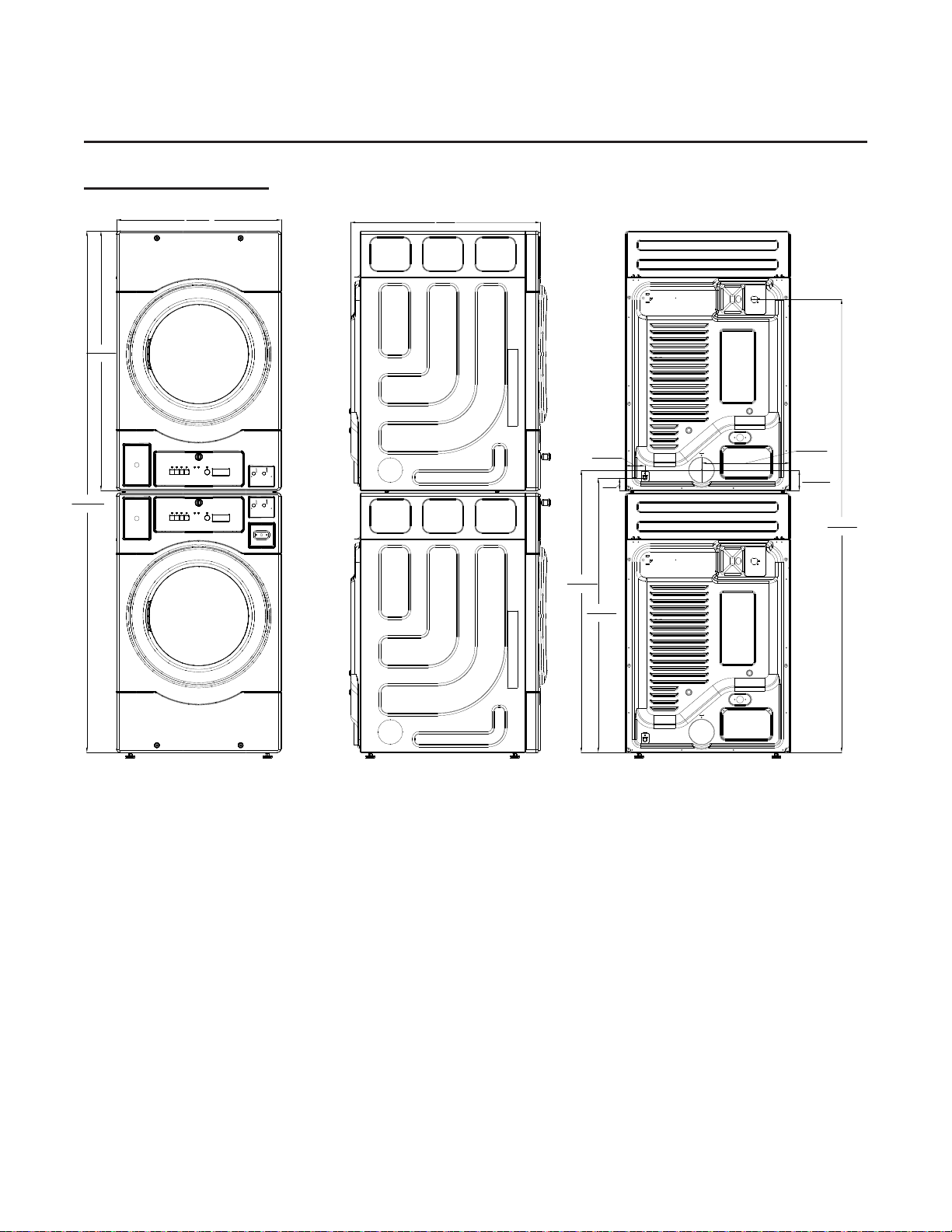
Technical Data
1:5
Dryer Dryer Stack
(inches/cm)

Installation
2:1
Installation Procedures
Installation should only be performed by qualied individuals in accordance with local, state, and
national codes. In the absence of these codes, the installation must conform to applicable American
National Standards: ANSI Z223.1- LATEST EDITION (National Fuel Gas Code) or ANSI/NFPA
NO. 70-LATEST EDITION (National Electrical Code) or in Canada, the installation must conform to
applicable Canadian Standards: CAN/CGA-B149.1-M91 (Natural Gas) or CAN/ CGA-B149.2-M91
(L.P. Gas) or LATEST EDITION (for General Installation and Gas Plumbing) or Canadian Electrical
Codes Parts 1 & 2 CSA C22.1-1990 or LATEST EDITION (for Electrical Connections).
Location Requirements
Before installing the dryer, be sure the location conforms to local, state, and national codes. In the
absence of such codes or ordinances the location must conform with the National Fuel Gas Code
ANSI.Z223.1 LATEST EDITION, or in Canada, the installation must conform to applicable Canadian
Standards: CAN/CGA-B149.1-M91 (Natural Gas) or CAN/ CGA-B149.2-M91 (L.P. Gas) or LATEST
EDITION (for General Installation and Gas Plumbing).
Unpacking / Setting Up
IMPORTANT
• Dryer must always be transported and handled in an upright position.
• Remove protective shipping material (i.e., plastic wrap and optional shipping box) from the dryer.
• All four leveling legs on stand-alone models are to be adjusted to level the dryer front to back,
and side to side.
• The machine should be positioned so that there is clearance for users and service personnel.
Installation
2:2
Dryer Enclosure Requirements
Commercial
• Bulkheads and partitions are recommended to be made of noncombustible material.
• The requirement to allow the door to open completely is 36 inches (91 cm).
• A minimum overhead clearance of 6-inches (15.24 cm) is recommended.
• Dryer should be positioned a minimum of 12-inches (30.5 cm) away from the nearest
obstruction. 24-inches (61 cm) is recommended for ease of installation, maintenance, and
service.
• Flooring should be level and below dryer cabinet for ease of removing panels during
maintenance.
• Dryers may be positioned side by side.
IMPORTANT
The Dryer – Dryer stacked unit is recommended to be installed by 2 people.
For stacked washer and dryer unit, the washer should be installed in accordance with washer
installation manual and tested rst.
Minimum clearances for closet and alcove installations: Sides 1", Rear 3", Top 1",
Front 3". Closet doors must be louvered or otherwise ventilated and have at least
60 square inches of open area.
WARNING

Installation
Fresh Air Supply Requirements
When the dryer is operating, it draws in room air, heats it, passes this air through the tumbler, and
exhausts it out of the building. The room air must be continually replenished from the outdoors
(make-up air). Replenishment of room air via HVAC systems is not acceptable. If the make-up air is
inadequate - product reliability, drying time and drying efciency may be adversely affected. Ignition
issues may also result in gas heated models.
Air supply (make-up air) must be given careful consideration to ensure proper performance of each
dryer. Fresh air ventilation openings shall not be blocked and/or sealed. Generally, an unrestricted
air entrance from the outdoors of 26 inch
2
(168 cm
2
) for each dryer. (Based on 1 inch
2
[6.5 cm
2
] per
1,000 Btu [252 kcal].)
It is not necessary to have a separate make-up air opening for each dryer. Common make-up air
openings are acceptable. However, they must be set up in such a manner that the make-up air is
distributed equally to all the dryers.
To compensate for the use of louvers used over the openings, this area must be increased by the
amount recommended by the supplier of the louvers. Make-up air openings should not be located in
an area directly near where exhaust vents exit the building.
Allowances must be made for remote or constricting passageways or where dryers are located at
high altitudes or predominantly low-pressure areas.
IMPORTANT
Component failure due to dry cleaning solvent fumes will void the warranty.
Exhaust Requirements
Exhaust ductwork should be designed and installed by qualied professional. Improperly sized
ductwork will create excessive back pressure, which results in slow drying, increased use of energy,
and possible shutdown of the dryer by a hi-limit thermostat. The dryer must be installed with a
proper exhaust duct connection leading to the outdoors.
The dryer shall not be exhausted into any gas vent, chimney, wall, ceiling or concealed space of a
building.
The condensate formed when operating the appliance from cold shall either be retained and
subsequently re-evaporated or discharged.
WARNING
• This dryer produces combustible lint and must be exhausted to the outdoors.
• Improperly sized or installed exhaust ductwork can create a potential re hazard.
• Use only smooth-walled metal ducting.
• Failure to install back draft dampers in shared dryer exhaust ducts can cause hazardous
conditions such backow of combustible gases.
The ductwork should be installed in such a way that the ductwork travels as directly as possible
to the outdoors. There should be a minimum 6-inch (15.24 cm) clearance between the back guard
and the rst bend in the ductwork for ease of servicing. Single or independent dryer venting is
recommended. It is suggested that the use of 90° turns be avoided; use 30° and/or 45° bends
2:3

Installation
2:4
wherever possible. All ductwork should be smooth inside with no projections from sheet metal
screws or other obstructions, which will result in lint accumulation. Duct sections must be oriented
for proper airow (consult duct supplier) and all joints must be taped to prevent moisture and lint
from escaping. Inspection doors should be installed at strategic points in the exhaust ductwork for
periodic inspection and cleaning of lint from the ductwork.
IMPORTANT
• It is recommended that exhaust or booster fans not be used in the exhaust ductwork system.
If an exhaust booster fan is required, care must be taken to meet all other installation
requirements.
• Exhaust back pressure measured by a manometer must be no less than 0 and must not exceed
0.6 in WC (1.5 mb).
• Do not obstruct the ow of makeup and exhaust air.
• Check backdraft dampers in the exhaust ductwork. Inspect and remove any lint accumulation,
which can cause the damper to bind or stick.
• A back-draft damper that is sticking partially closed can result in slow drying and shutdown of
the machine due to activation of a high limit thermostat.
IMPORTANT
When the exhaust ductwork passes through a wall, ceiling, or roof, installation must comply with
applicable local and national codes.
Refer to the National Fuel Gas Code and applicable local codes for ducting requirements.
Outside Ductwork Protection
To protect the outside end of the horizontal ductwork from the weather, a 90° elbow bent downward
should be installed where the exhaust exits the building. If the ductwork travels vertically up
through the roof, it should be protected from the weather by using a 180° turn to point the opening
downward. In either case, allow at least twice the diameter of the duct between the duct opening
and the nearest obstruction.
IMPORTANT
Do not use screens, louvers, or caps on the outside opening of the exhaust ductwork.
Single Dryer Venting
IMPORTANT
For extended ductwork runs, the cross-sectional area of the ductwork can only be increased to an
extent. When the ductwork approaches the maximum limits as noted in this manual, a professional
HVAC rm should be consulted for proper venting design.
Horizontal Venting
If the dryer is installed using horizontal dryer venting, the overall length of the ductwork from
the dryer to the outside exhaust outlet, must not exceed 20 feet (6 meters). The diameter of this

Installation
ductwork must be 4-inches (10 cm). No more than 1 elbow should be used in the exhaust duct run
(including tumbler/dryer elbow connections or elbows used for outside protection from the weather).
If more than 1 elbow is used, the cross-sectional area of the ductwork must be increased.
Vertical Venting
If vertical dryer venting is used, the length of the ductwork from the dryer to the outside exhaust
outlet, must not exceed 12 feet (3.5 meters). The diameter of this ductwork must be 4-inches
(10 cm). No more than 3 elbows should be used in the exhaust duct run (including tumbler/dryer
elbow connections or elbows used for outside protection from the weather). If more than 3 elbows
are used, the cross-sectional area of the ductwork must be increased.
Multiple Dryer (Common) Venting
If it is not feasible to provide separate exhaust ducts for each dryer, ducts from individual dryers
may be channeled into a “common main duct.” The individual ducts should enter the bottom or side
of the main duct at an angle not more than 45º in the direction of airow. The main duct should be
tapered, with the diameter increasing before each individual duct is added. The multiple dryers must
have separate backdraft dampers when connected through a shared venting.
IMPORTANT
• No more than four dryers should be connected to one main common duct.
The illustration below shows the minimum cross-sectional area for multiple dryer round or square
venting. These gures must be increased if the main duct run from the last dryer to where it
exhausts to the outdoors is longer than 12 feet (3.5 meters) or has more than one elbow in it.
NOTE
• Clearance to surfaces adjacent to ductwork must comply with applicable national and local
codes.
• Distance should be 2 times the diameter of the duct to the nearest obstruction.
NUMBER OF DRYERS 4 3 2 1
MINIMUM CROSS-
SECTIONAL AREA
SQ IN 80 80 54 30
MINIMUM ROUND
DUCT DIAMETER
IN 10 10 8 6
2:5

Installation
2:6
Electrical Requirements
All electrical connections must be made by a properly licensed qualied electrician. This is to
ensure that the electrical installation is adequate and conforms to local, state, and national codes
in the country of installation. In the absence of such codes, all electrical connections, materials,
and workmanship must conform to the applicable requirements of the National Electrical Code
ANSI/NFPA NO.70-LATEST EDITION or in Canada, the Canadian Electrical Codes Parts 1 & 2
CSA C22.1-1990 or LATEST EDITION.
WARNING
• Failure to comply with these codes or ordinances, and/or the requirements stipulated in this
manual can result in personal injury or component failure.
• Component failure due to improper voltage application will void the warranty.
• Component failure due to improper installation will void the warranty.
IMPORTANT
• A separate branch circuit must be provided for each dryer.
• The dryer must be connected to the electric supply shown on the data label any damage
done to dryer components due to improper voltage connections will void the warranty.
Electrical Service Specications
Gas Heated Models
Electric Heated Models
All electrically heated dryers must be connected to the electric service shown on the dryer’s data
label. The connecting wires must be properly sized to handle the rated current.
Grounding
A ground (earth) connection must be provided and installed in accordance with local, state,
and national codes. In the absence of these codes, grounding must conform to applicable
requirements of the National Electrical Code ANSI/NFPA NO. 70-LATEST EDITION, or in
Canada, the installation must conform to applicable Canada Standards: Canadian Electrical
Codes Parts 1 & 2 CSA C22.1-1990 or LATEST EDITION.
ELECTRICAL SERVICE SPECIFICATIONS (PER POCKET)
SERVICE
VOLTAGE
PHASE
WIRE
SERVICE
APPROX. AMP
DRAW
CIRCUIT
BREAKER
60 Hz
120 1ø 2 6.8 A 15 A
ELECTRICAL SERVICE SPECIFICATIONS (PER POCKET)
SERVICE
VOLTAGE
PHASE
WIRE
SERVICE
APPROX. AMP
DRAW
CIRCUIT
BREAKER
60 Hz
120/240V 1ø 3 24 A 30 A
120/208V 3ø 3 23 A 30 A
Installation
2:7
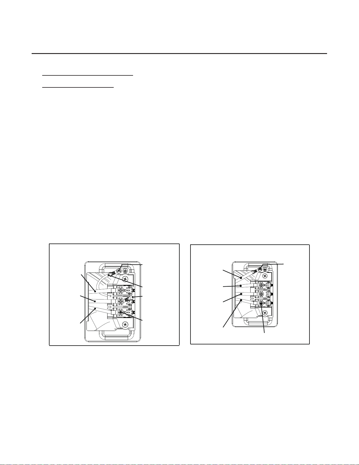
Wiring Connections / Hookup
Electric Heated Models
When local codes allow, the electrical supply of the dryer may be connected by means of a new
power supply cord kit, marked for use with a dryer, that is U.L. listed and rated at a minimum of
120/240 volts, 30-ampere with three No. 10 copper wire conductors terminated with closed loop
terminals, open-end spade lugs with turned up ends, or with tinned leads.
The electrical input connections are made into the rear service compartment of the dryer.
All electrically heated dryers are 120/208V,120/240V single-phase that require grounding of neutral
wire and ground. A ground lug has been provided for this purpose, see Figure A.
Note that machines sold in Canada are factory-equipped with a power cord and four-prong plug,
see Figure B.
CAUTION: A 4-conductor cord shall be used when the appliance is installed in a location
where grounding through the neutral conductor is prohibited. Grounding through the
neutral conductor is prohibited for (1) new branch-circuit installations, (2) mobile homes,
(3) recreational vehicles, and (4) areas where local codes prohibit grounding through the
neutral conductors.
Input connection wiring must be properly sized to carry the dryer’s current draw. This information
is printed on the dryer’s data label. Electrically heated dryers are not equipped with a line cord
from the factory. A suitable line cord must be provided by the installer. The dryer’s input terminal
block includes a bonding jumper wire between the neutral wire terminal of the power-input terminal
block and chassis of the machine. This bonding jumper MUST be removed for four wire line cord
connection. Refer to local and national codes for specic connection requirements.
3-Wire Connection
Ground Screw
(Green)
L1
Power cord
L2
Power cord
Power Cord
(White)
Neutral-Ground
Jumper Wire
(White)
Terminal
Block Screw
Neutral Wire
N
4-Wire Connection
L1
Power Cord
L2
Power Cord
Power Cord
Ground
Wire(Green)
Terminal Block Screw
Power Cord
(White)
Neutral Wire
N
Ground
Screw
(Green)
Figure A Figure B

Installation
Wiring Connections / Hookup
Gas Heated Model
All gas model dryers are 120 volts and come with an integrated 3-prong NEMA plug
intended for connection to a dedicated branch receptacle.
Gas Information
Gas installation and adjustment must be done by qualied, licensed personnel. It is your
responsibility to have all plumbing connections, materials, and workmanship comply with
national and local codes in the country of installation. In the absence of such codes, all
plumbing connections, materials, and workmanship must comply with the National Fuel Gas
Code ANSI Z223.1-LATEST EDITION, or in Canada, the Canadian Installation Codes CAN/
CGA-B149.1-M91 (Natural Gas) or CAN/CGAB149.2-M91 (L.P. Gas) or LATEST EDITION.
It is important that any gas pressure regulators meet the requirements of all installed
appliances.
IMPORTANT
• Failure to comply with applicable codes, and the requirements stipulated in this manual,
can result in personal injury and improper operation of the dryer.
• For ease of service, the individual gas supply line of each dryer must have its own
manual shutoff valve.
• The dryer must be disconnected from the gas supply piping system during pressure
testing.
• Failure to isolate or disconnect the dryer from the gas supply as noted can cause
irreparable damage to the gas valve, voiding the warranty.
• Undersized gas piping will result in ignition problems, slow drying, increased use of
energy, and can create a safety hazard.
• The manufacturer of this appliance does not recommend the use of exible gas supply
line/hose. If permitted by applicable codes, the exible line must be suitable for the
appliance category.
Grounding Information
This appliance must be grounded. In the event of malfunction or breakdown, grounding
will reduce the risk of electric shock by providing a path of least resistance for electric
current. This appliance is equipped with a cord having an equipment-grounding conductor
and a grounding plug. The plug must be plugged into an appropriate outlet that is properly
installed and grounded in accordance with all local codes and ordinances.
WARNING
• Improper connection of the equipment grounding conductor can result in a risk of
electric shock. Check with a qualied electrician or service representative or personnel
if you are in doubt as to whether the appliance is properly grounded. Do not modify the
plug provided with your dryer- if it will not t the outlet, have a proper outlet installed by
a qualied electrician.
2:8
Installation
2:9
WARNING
• Fire or explosion could result due to failure to isolate or disconnect the gas supply as noted.
The dryer must be connected to the type of heat/gas indicated on the data label and the correct
pressure must be conrmed. If this is not possible, do not connect the dryer. Contact the reseller
who sold the dryer or the manufacturer.
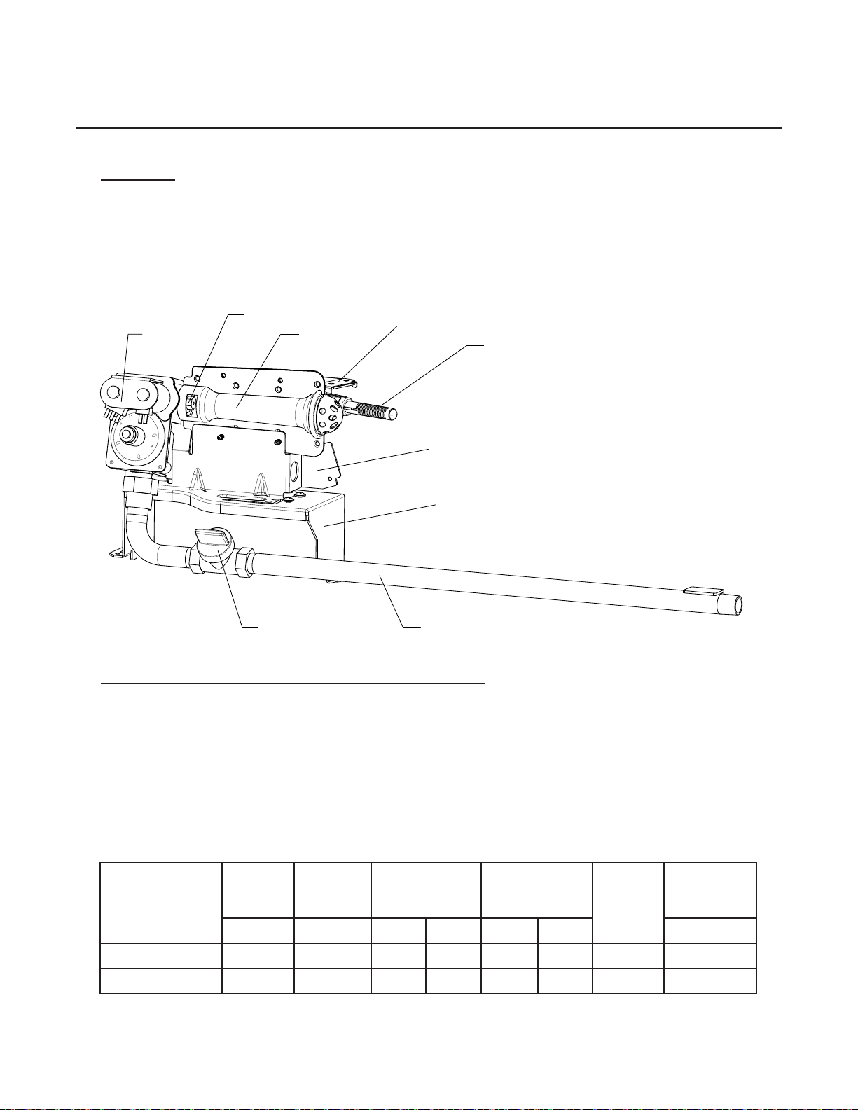
Heat Input / Gas Consumption/Orice (Injector) Data
Consistent gas pressure is essential at all dryer gas connections. It is recommended that a 3/4-
inch (19mm) pipe gas loop be installed in the supply line servicing a bank of dryers. For natural
gas installation an in-line pressure regulator must be installed in the gas supply line if the gas
pressure exceeds 10.0 in WC (25 mb) pressure.
A plugged tap, accessible for a pressure gauge connection, must be installed in the main gas
supply line immediately upstream of the dryers.
NG
LPG
IGNITOR
GAS NOZZLE
GAS VALVE
GAS PIPE
GAS SHUTOFF VALVE
GAS VALVE BRACKET
GAS VALVE ASSEMBLY BASE
BURNER
IGNITOR BRACKET
Gas Type
Nominal
Heating
Value
Supply
Pressure
Gross Heat
Input
Orice
Size
Orice
Injector
Quantity
Burner
Pressure
Btu/ft
3
In-WC Btu/hr kW DMS mm In-WC
Natural Gas 1000 4.5 - 10.5 19000 5.5 44 2.2 1 3
Liquid Propane 2500 11 - 14 19000 5.5 55 1.3 1 10.5

Installation
WARNING
• Never test for leaks with a ame!!!
WARNING
• This appliance must only be operated with the gas type indicated on the dryer’s data
plate. If the appliance is converted (gas type changed), a data plate amendment must
be obtained from the manufacturer (dryer’s serial number is required to purchase a
conversion kit).
IMPORTANT
• Any burner changes or conversions must be made by qualied personnel.
CONVERSION FROM NATURAL GAS TO PROPANE GAS
WARNING
This procedure must be carried out by a qualied, licensed gas-appliance technician.
• Disconnect electrical power to the dryer.
• Close all shut-off valves in the dryer’s gas supply line.
• Open the toe panel of the dryer.
• Disconnect ignitor wires from harness and
then remove the burner tube.
• Remove the burner orice from the valve
and replace it with the proper orice. Use
orice # 44 for NG and orice # 55 for LP.
Orice number is stamped on the edge of
the hex head of the orice. Securely tighten.
• Put the burner tube on the burner assembly.
Securely tighten.
• Reconnect the ignitor to the harness.
• Observe the cover dial settings indicated
as NG and LP along with the gas type
indicator.
• Position a pair of needle nose pliers into the
slots of the cover dial.
• Rotate the cover dial to line up with LP
marking with the indicator on the gas valve.
WARNING
• Improper FUEL Conversions can result in re or explosion!
2:10

Installation
2:11
Gas Pressure Adjustment
Disconnect electrical power to the dryer.
Gas (burner) pressures are measured with the burner in operation for all burner adjustment
conditions. Therefore once the necessary adjustments have been made, the dryer must be
operated in a heating cycle to verify that the pressure is correct. If it is not correct, you must
discontinue the power to the unit and make further adjustments. Repeat these steps as many
times as necessary to achieve the correct burner pressure. Once the adjustment of the valve
is complete, the vent cap must be replaced and sealed with, for example, paint to prevent
maladjustment by the user.
Gas Pressure Testing
For proper operation, the gas supply and regulated pressures must be correct. Verify correct
pressure according to the instructions below. This procedure must be carried out by qualied,
licensed personnel.
WARNING
• Turn gas shutoff valve in gas supply line to “OFF” position.
• Install a pressure tap tting and attach a manometer.
• Turn gas shutoff valve to “ON” position
• Start the dryer in Heat Mode and wait for ignition. Gas manifold pressure should be specied
for the applicable fuel.
If the gas pressure needs to be adjusted, refer to “Gas Pressure Adjustment” in this section.
• Once test is complete, turn shutoff-valve to “OFF” position. Remove manometer. Tighten
screw inside the pressure tap or install plug.
• Turn gas shutoff-valve to “ON” position and check for leaks with soap solution with at the
pressure tap with the burner on.

Pre Operational Instructions
The following items should be checked before attempting to operate the dryer:
• Read all “IMPORTANT” AND “WARNING” labels attached to the dryer.
• Check incoming supply voltage to be sure that it is the same as indicated on the data label.
• GAS MODELS – Check to ensure that the dryer is connected to the type of gas indicated on
the dryer data label.
• GAS MODELS – Be sure that all gas shutoff valves are in the open position.
• Be sure all back panels (guards) and electric box covers are in place.
• Be sure the service doors are closed and securely in place.
• Be sure the lint lter is securely in place.
• Rotate the tumbler (drum) by hand in both directions to be sure it moves freely.
• Check bolts, nuts, screws, terminals, and ttings for tightness and security.
• Check that the vent is connected to the dryer and is exhausted to the outdoors.
Function Checks
All dryers are thoroughly tested and inspected before leaving the factory. However, a test should be
performed before the dryer is publicly used. It is possible that adjustments have changed in transit
or due to marginal location (installation) conditions.
Gas Dryers
• Open all shutoff valves.
• Turn on electric power to the dryer.
• Run the “No Heat” drying program and check if the drum is rotating properly.
• Run the “Low Heat” and to check the Ignition.
• Refer to the Operating Instructions for starting your particular model dryer.
When a gas dryer is rst started (during initial start-up), it has a tendency not to ignite on the rst
ignition attempt. This is because the gas supply piping is lled with air, so it may take a few minutes
for the air to be purged from the lines.
NOTE
• During the purging period, check to be sure that all gas shutoff valves are open.
• A gas pressure test should be taken at the gas valve pressure tap of each dryer to ensure that
the water column pressure is correct and consistent.
• Water column pressure requirements (measured at the pressure tap of the gas valve body)
must be veried.
• Dryers congured for L.P. operation do not have a regulator. The water column pressure must
be regulated at the source (L.P. tank), or an external regulator must be added to each dryer’s
L.P. connection line.
3:1

Pre Operational Instructions
3:2
Electrical Heated Dryers
• Turn on electric power to the dryer.
• Run the “No Heat” drying program and check if the drum is rotating properly.
• Check to ensure that electric oven/contactor assembly is activating.
• Run the “Low Heat” and to check the Ignition
• Refer to the Operating Instructions for starting your particular model dryer.
Shutdown Instructions
If the dryer is to be shutdown (taken out of service) for a period of time, the following must be
performed:
• Disconnect power to the dryer either at the external disconnect switch or the circuit breaker.
Gas Models
• Turn off external gas supply shutoff valve.
5:1
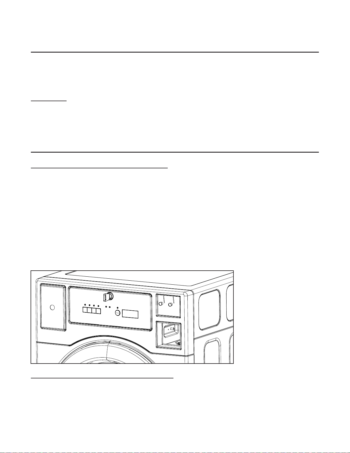
Coin Meter Installation and Blocking Plate
Install the Coin Meter (Coin Operated Models)
1. Unlock control panel with the provided key.
2. Loosen four screws in the control panel.
3. Demount the control panel seat.
4. Install the coin meter faceplate into the control panel and then assemble the coin meter(s) into
the faceplate.
5. Plug the coin meter(s) into COIN 1 (Red) and COIN 2 (Red) harnesses inside the dryer.
6. Carefully reattach the coin meter harnesses using the cable ties mounted on the chassis behind
the coin meter(s). Make sure the harnesses do not obstruct coins dropping into the coin vault
and that they do not touch moving parts on the sides of the coin meter(s).
7. Reinstall the control panel seat by using the four screws, then and locking main control panel.
Install the Blocking Plate (Non Metered Models)
1. Push the blocking plate into the coin vault until the tabs lock in place.
4:1

Preventive Maintenance
6:1
Cleaning
A program and/or schedule should be established for periodic inspection, cleaning, and removal
of lint from various areas of the dryer, as well as throughout the ductwork system. The frequency
of cleaning can best be determined from experience at each location. Maximum operating
efciency is dependent upon proper airow. The accumulation of lint can restrict this airow. If
the guidelines in this section are met, the dryer will provide many years of efcient, trouble free,
and most importantly, safe operation.
Daily
• Clean the lint screen after each load.
Weekly
• Clean lint accumulation from lint chamber, and temperature sensor area.
• See illustration below.
• Clean the door gasket.
• Use a soft wash cloth and mild detergent to clean door.
Every Third Month
• Disconnect Power.
• Remove lint from gas valve burner area with a dusting brush or vacuum cleaner attachment.
• Vacuum make up air inlet holes. On removing the lint lter from the lint compartment, clean
lint in the lint compartment.
• Clean any lint accumulation in and around the motor(s) casing opening.
• NOTE: To prevent damage, avoid cleaning and/or touching ignitor/ame-probe assembly.
Outlet Thermistor (NTC - 1)
Preventive Maintenance
6:2
Every 6 Months (Refer this service to qualied personnel)
• Inspect and remove lint accumulation external exhaust ductwork and from dryer’s internal
exhaust ducting.
• The accumulation of lint in the exhaust ductwork can create a potential re hazard.
• Do not obstruct the ow of combustion and ventilation air. Check back draft dampers in the
exhaust ductwork. Inspect and remove any lint accumulation, which can cause the damper
to bind or stick. Obstructed ducting leads to longer drying times, higher energy consumption.
and reduced motor life
• If ducting is highly obstructed with lint change to a shorter service interval such as every
three months.
• A back-draft damper that is sticking partially closed can result in slow drying and the
shutdown of heat circuit safety switches or thermostats.
• When cleaning the dryer cabinet, avoid using cleaners with harsh abrasives. A product
intended for appliance cleaning is recommended.
Every 12 Months
• A competent professional should inspect bolts, nuts, screws, setscrews, grounding
connections and nonpermanent gas connections (unions, shutoff valves, and orices).
• Belts should be examined. Cracked or seriously frayed belts should be replaced.
• Complete an operational check of controls and valves.
• Complete an operational check of all safety devices (lint door switch, door switch).
To be carried out by
qualied personnel.

Sales and Administration: (516) 371-4400
Spare Parts: (516) 371-2000
Technical Support: (516) 371-0700
En Mexico: 001-800-010-1010
461 Doughty Blvd., Inwood, NY 11096
laundrylux.com