
V1.0.0
Unit VTO (Version 4.6)
User's Manual
Foreword
This manual introduces the structure and conguration of the unit VTO. Read carefully before using
the VTO, and keep the manual safe for future reference.
Safety Instructions
The following signal words might appear in the manual.
Signal Words Meaning
Indicates a high potential hazard which, if not avoided, will result in
death or serious injury.
Indicates a medium or low potential hazard which, if not avoided, could
result in slight or moderate injury.
Indicates a potential risk which, if not avoided, could result in property
damage, data loss, reductions in performance, or unpredictable results.
Provides methods to help you solve a problem or save time.
Provides additional information as a supplement to the text.
Revision History
Version Revision Content Release Time
V1.0.0 First release. May 2023
Privacy Protection Notice
As the device user or data controller, you might collect the personal data of others such as their
face, ngerprints, and license plate number. You need to be in compliance with your local privacy
protection laws and regulations to protect the legitimate rights and interests of other people by
implementing measures which include but are not limited: Providing clear and visible identication
to inform people of the existence of the surveillance area and provide required contact information.
About the Manual
●
The manual is for reference only. Slight dierences might be found between the manual and the
product.
●
We are not liable for losses incurred due to operating the product in ways that are not in
compliance with the manual.
●
The manual will be updated according to the latest laws and regulations of related jurisdictions.
For detailed information, see the paper user’s manual, use our CD-ROM, scan the QR code or
visit our ocial website. The manual is for reference only. Slight dierences might be found
between the electronic version and the paper version.
●
All designs and software are subject to change without prior written notice. Product updates
might result in some dierences appearing between the actual product and the manual. Please
contact customer service for the latest program and supplementary documentation.
I

●
There might be errors in the print or deviations in the description of the functions, operations
and technical data. If there is any doubt or dispute, we reserve the right of nal explanation.
●
Upgrade the reader software or try other mainstream reader software if the manual (in PDF
format) cannot be opened.
●
All trademarks, registered trademarks and company names in the manual are properties of their
respective owners.
●
Please visit our website, contact the supplier or customer service if any problems occur while
using the device.
●
If there is any uncertainty or controversy, we reserve the right of nal explanation.
II
Important Safeguard and Warnings
This section introduces content covering the proper handling of the device, hazard prevention, and
prevention of property damage. Read carefully before using the device, and comply with the
guidelines when using it.
Operation Requirements
●
Check whether the power supply is correct before use.
●
Do not unplug the power cord on the side of the device while the adapter is powered on.
●
Operate the device within the rated range of power input and output.
●
Transport, use and store the device under allowed humidity and temperature conditions.
●
If the device is powered o for longer than a month, it should be placed in its original package
and sealed. Make sure to keep it away from moisture, and store it under allowed humidity and
temperature conditions.
●
Do not drop or splash liquid onto the device, and make sure that there is no object lled with
liquid on the device to prevent liquid from owing into it.
●
Do not disassemble the device without professional instruction.
Installation Requirements
●
Do not connect the power adapter to the device while the adapter is powered on.
●
Strictly comply with the local electric safety code and standards. Make sure the ambient voltage
is stable and meets the power supply requirements of the device.
●
Do not connect the device to two or more kinds of power supplies, to avoid damage to the
device.
●
Improper use of the battery might result in a re or explosion.
●
Personnel working at heights must take all necessary measures to ensure personal safety
including wearing a helmet and safety belts.
●
Do not place the device in a place exposed to sunlight or near heat sources.
●
Keep the device away from dampness, dust, and soot.
●
Install the device on a stable surface to prevent it from falling.
●
Install the device in a well-ventilated place, and do not block its ventilation.
●
Use an adapter or cabinet power supply provided by the manufacturer.
●
Use the power cords that are recommended for the region and conform to the rated power
specications.
●
The power supply must conform to the requirements of ES1 in IEC 62368-1 standard and be no
higher than PS2. Please note that the power supply requirements are subject to the device label.
●
The device is a class I electrical appliance. Make sure that the power supply of the device is
connected to a power socket with protective earthing.
III

目录
Foreword........................................................................................................................................................................................................ I
Important Safeguard and Warnings...................................................................................................................................................III
1 Product Overview................................................................................................................................................................................... 1
1.1 Introduction..................................................................................................................................................................................1
1.2 Function......................................................................................................................................................................................... 1
1.3 Front Panel.................................................................................................................................................................................... 2
1.3.1 65 Series.............................................................................................................................................................................2
1.3.2 75 Series.............................................................................................................................................................................4
1.3.3 95 Series.............................................................................................................................................................................5
1.4 Rear Panel......................................................................................................................................................................................5
1.4.1 65 Series.............................................................................................................................................................................6
1.4.2 75 Series.............................................................................................................................................................................8
1.4.3 95 Series.......................................................................................................................................................................... 10
2 VTO Operation.......................................................................................................................................................................................12
2.1 65 Series.......................................................................................................................................................................................12
2.1.1 Home Screen................................................................................................................................................................. 12
2.1.2 Engineering Setting....................................................................................................................................................13
2.2 75/95 Series................................................................................................................................................................................ 27
2.2.1 Home Screen................................................................................................................................................................. 28
2.2.2 Engineering Setting....................................................................................................................................................29
2.2.3 Owner Registration..................................................................................................................................................... 43
2.2.4 Unlock..............................................................................................................................................................................47
2.2.5 Call.....................................................................................................................................................................................49
2.2.6 Messages.........................................................................................................................................................................50
3 Webpage Operations..........................................................................................................................................................................51
3.1 Logging in to the Webpage................................................................................................................................................. 51
3.2 Resetting the Password..........................................................................................................................................................51
3.3 Home Page Introduction.......................................................................................................................................................52
3.4 Changing the User Message.................................................................................................................................................53
3.5 Import/Export the Device Information.............................................................................................................................54
3.5.1 Importing the Device Information........................................................................................................................ 54
3.5.2 Exporting the Device Information.........................................................................................................................54
3.6 Import/Export the User Information................................................................................................................................. 54
3.6.1 Importing the User Information.............................................................................................................................54
3.6.2 Exporting the User Information..............................................................................................................................55
3.7 Local Setting...............................................................................................................................................................................55
IV

3.7.1 Conguring Video and Audio Parameters..........................................................................................................55
3.7.2 Conguring Access Control Parameters............................................................................................................. 59
3.7.3 Conguring System Parameters............................................................................................................................ 61
3.7.4 Conguring Security Management.......................................................................................................................63
3.7.5 Conguring Wiegand Parameters.........................................................................................................................64
3.7.6 Conguring Face Detection Parameters.............................................................................................................64
3.7.7 Adding ONVIF Users................................................................................................................................................... 66
3.7.8 Conguring Fingerprint Recognition Parameters...........................................................................................67
3.7.9 Uploading Audio Files................................................................................................................................................67
3.7.10 Viewing the Legal Information.............................................................................................................................68
3.8 Household Setting................................................................................................................................................................... 68
3.8.1 Adding the VTO............................................................................................................................................................68
3.8.2 Adding the VTH............................................................................................................................................................ 68
3.8.3 Adding the VTS.............................................................................................................................................................68
3.8.4 Adding the IPC..............................................................................................................................................................69
3.8.5 Viewing the Online Devices.....................................................................................................................................72
3.8.6 Announcement............................................................................................................................................................ 72
3.8.7 Personnel Management............................................................................................................................................73
3.9 Network....................................................................................................................................................................................... 75
3.9.1 Conguring the Basic Parameters......................................................................................................................... 75
3.9.2 Conguring UPnP Service........................................................................................................................................ 82
3.9.3 Conguring the SIP Server....................................................................................................................................... 85
3.9.4 Firewall............................................................................................................................................................................ 85
3.10 Logs.............................................................................................................................................................................................87
3.10.1 Viewing the Call Records........................................................................................................................................87
3.10.2 Searching the Alarm Records................................................................................................................................88
3.10.3 Searching the Records of unlocking the door................................................................................................ 88
3.10.4 Searching the System Logs....................................................................................................................................89
3.11 Restarting the Device........................................................................................................................................................... 90
3.12 Restoring to Factory Defaults............................................................................................................................................90
3.13 Logging Out.............................................................................................................................................................................90
Appendix 1 Cybersecurity Recommendations........................................................................................................................... 91
V

1 Product Overview
1.1 Introduction
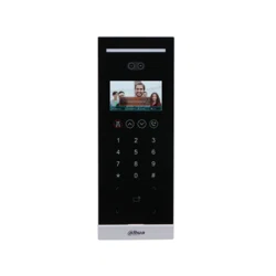
The Digital Door Station (hereinafter referred to as "VTO") uses capacitive touch screen and
anodized aluminum frame, and is equipped with 2-MP dual-lens network camera. The VTO
integrates deep learning algorithm to enable the user open the door through the recognition
function. There are multiple authentication methods, such as QR code recognition, ngerprint
recognition and password opening. Supports emergency call, announcement, log search and other
functions. The VTO is generally used in residential areas.
1.2 Function
Video and Voice Call
Makes video and voice calls to the VTH or the VTS.
Group Call
If the current VTO works as the SIP server, it can call many VTHs at the same time.
Emergency Call
Directly calls the management center in an emergency.
Unlock
●
Unlock through the face: The VTO recognizes the face using the latest deep learning algorithm
and opens the door.
●
Unlock through the ngerprint: The built-in ngerprint module recognizes the ngerprint.
●
Unlock through the QR code: The VTO recognizes the QR code to open the door.
Being Monitored
The VTH or the management center can monitor the VTO. The VTO supports up to 6 streams for
monitoring.
Auto Snapshot
Takes snapshots while you are on a call or unlocking the door, and stores them to the SD card.
1

Access Control
Directly controls the locks.
Alarm Management
The VTO has functions of tamper alarm and door detector detection alarm.
Linkage with the Elevator
Connect with the elevator to enable the elevator control linkage function.
IR Smart Illumination
Automatically detects the actual scenery and opens the illumination.
Standalone Operation
Issues the cards, registers the ngerprints and the faces through the device.
Sub VTO Management
The main VTO can connect with up to 9 sub VTOs in the same unit.
Announcement
Sends the announcement to the VTH.
Log Search
Supports searching for the call log, alarm log and unlock log.
1.3 Front Panel
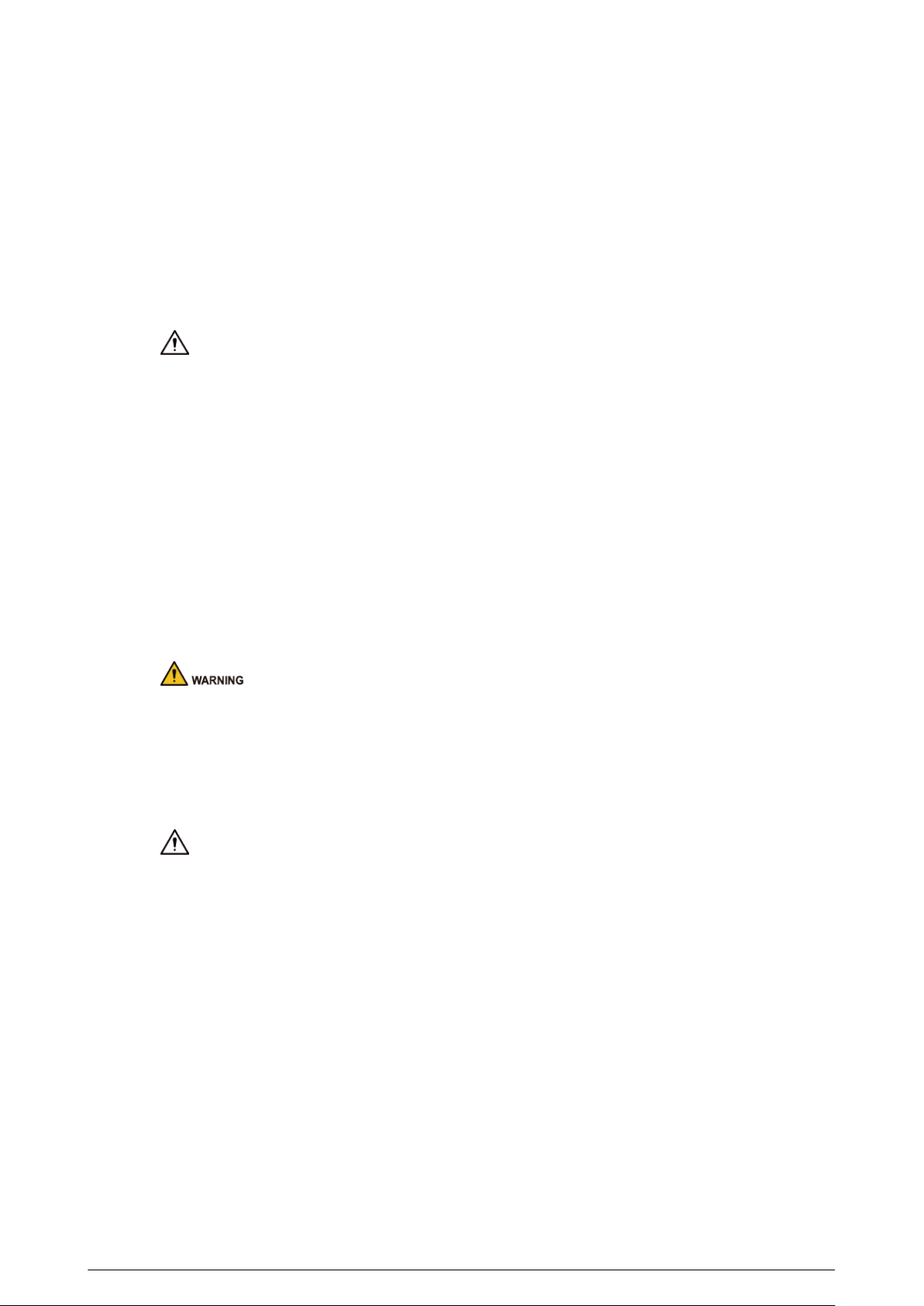
1.3.1 65 Series
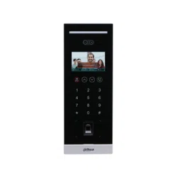
The device models on the rst row in the following gure are VTO6521F and VTO6521H. The device
models on the second row in the following gure are VTO6531H and VTO6541H.
2
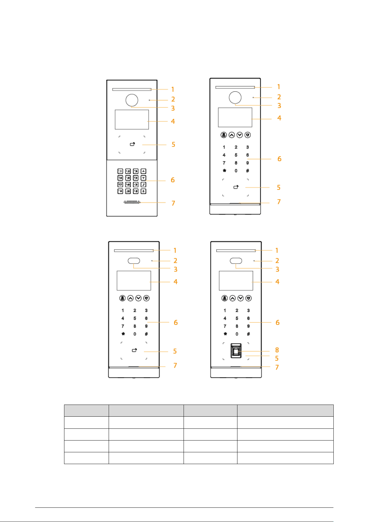
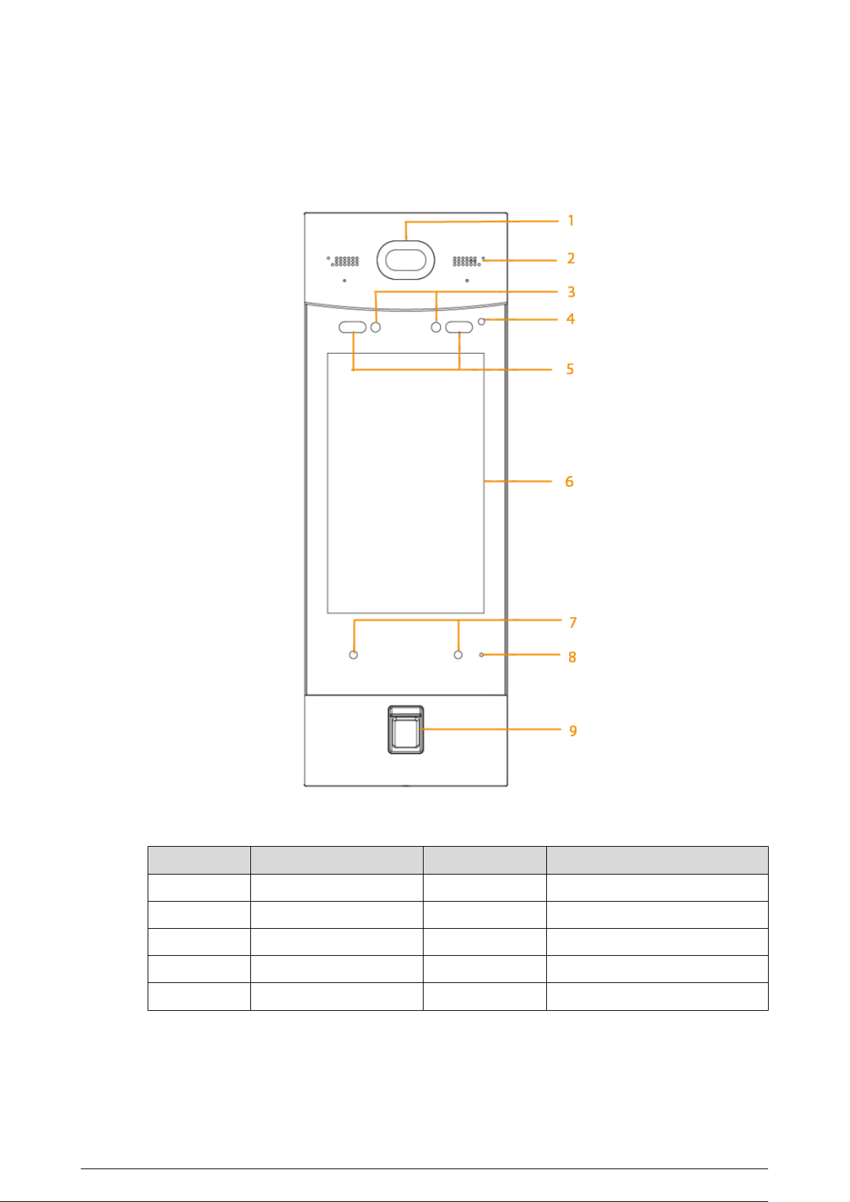
Figure 1-1 Front panel
Table 1-1 Component description
No.
Description No. Description
1 White illuminator 5 Card swiping area
2 MIC 6 Keyboard
3 Camera 7 Loudspeaker
4 Display 8 Fingerprint sensor
3
1.3.2 75 Series
Figure 1-2 Front panel
Table 1-2 Component description
No.
Description No. Description
1 Camera 5 Card swiping area
2 White illuminator 6 Fingerprint sensor
3 MIC 7 Loudspeaker
4 Display — —
4
1.3.3 95 Series
Figure 1-3 Front panel
Table 1-3 Component description
No.
Description No. Description
1 Camera 6 Display
2 Loudspeaker 7 Proximity sensor
3 IR right 8 MIC
4 Phototransistor 9 Fingerprint sensor
5 White illuminator — —
1.4 Rear Panel
5
1.4.1 65 Series
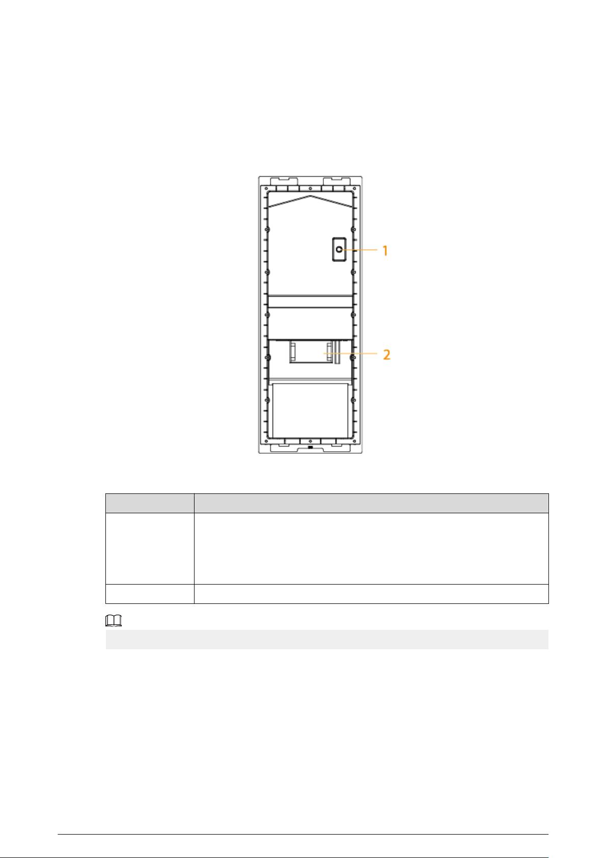
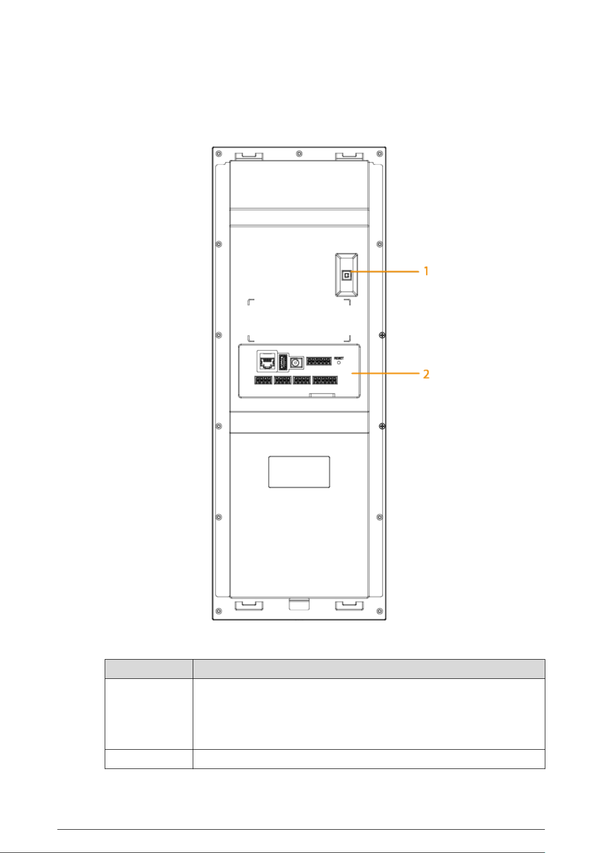
Figure 1-4 Rear panel
Table 1-4 Component description
No.
Description
1
Tamper button
Within 5 minutes after the device is powered on, if you continuously press the
tamper button for 5 times in 8 seconds, the device beeps and deletes the
account information.
2 Functions ports (connected to locks, access controllers, alarm in/out devices)
For details about power port, network port and other ports, see Figure 1-5 .
6
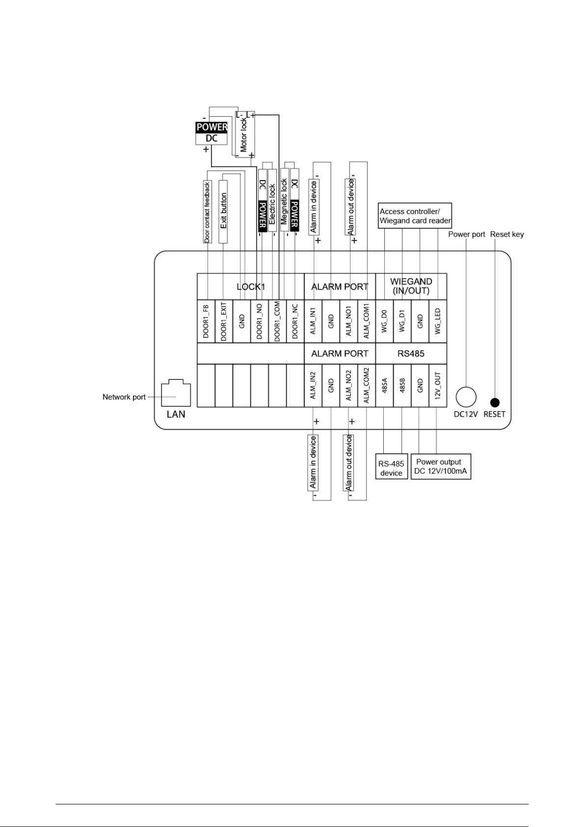
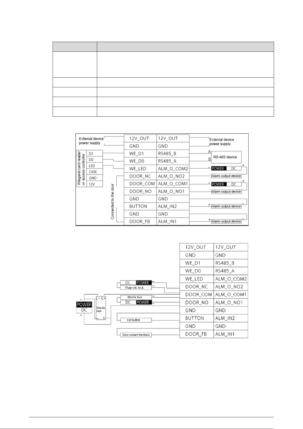
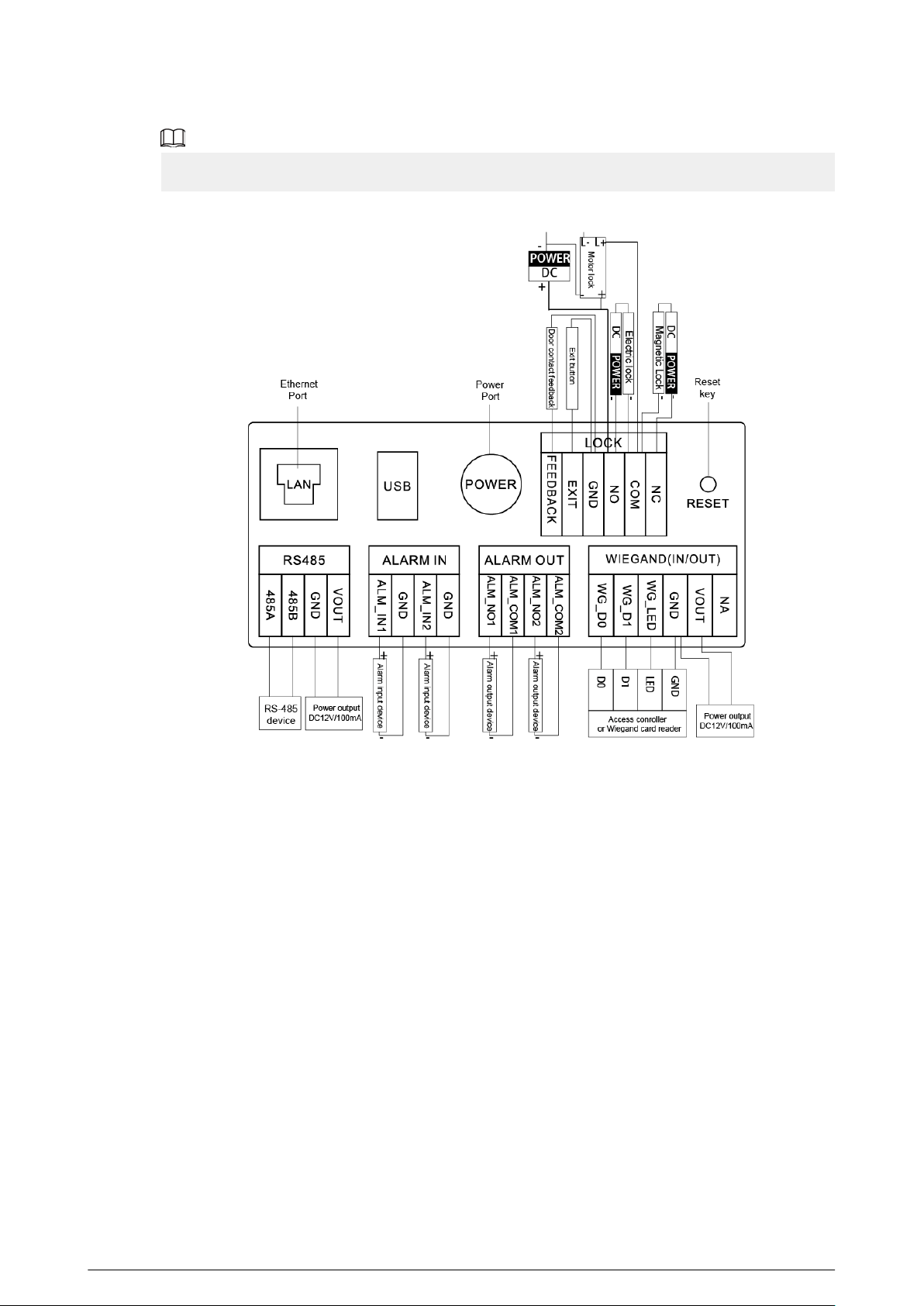
Figure 1-5 Cable connection
Reset: Press the reset button for more than 8 seconds to restore the device to its factory defaults.
The IP, account, conguration and the database information are deleted.
7
1.4.2 75 Series
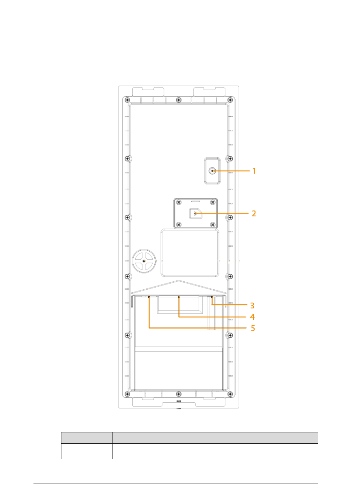
Figure 1-6 Rear panel
Table 1-5 Component description
No.
Description
1 Tamper button
8
No. Description
Within 5 minutes after the device is powered on, if you continuously press the
tamper button for 5 times in 8 seconds, the device beeps and deletes the
account information.
2 SIM card cover
3 Power port
4 Function ports (such as alarm in/out port, lock port, and wiegand port)
5 Ethernet port
Figure 1-7 Cable connection (1)
Figure 1-8 Cable connection (2)
9
1.4.3 95 Series
Figure 1-9 Rear panel
Table 1-6 Component description
No.
Description
1
Tamper button
Within 5 minutes after the device is powered on, if you continuously press the
tamper button for 5 times in 8 seconds, the device beeps and deletes the
account information.
2 Function ports
10
2 VTO Operation
This chapter introduces the operations on the devices and uses 2 types as examples according to
the displayed screen.
2.1 65 Series
The 65 series devices use the following screen style.
The following snapshots of the devices are for reference only, and slight dierences might be found
in the operation screen of the VTO, depending on your model.
2.1.1 Home Screen
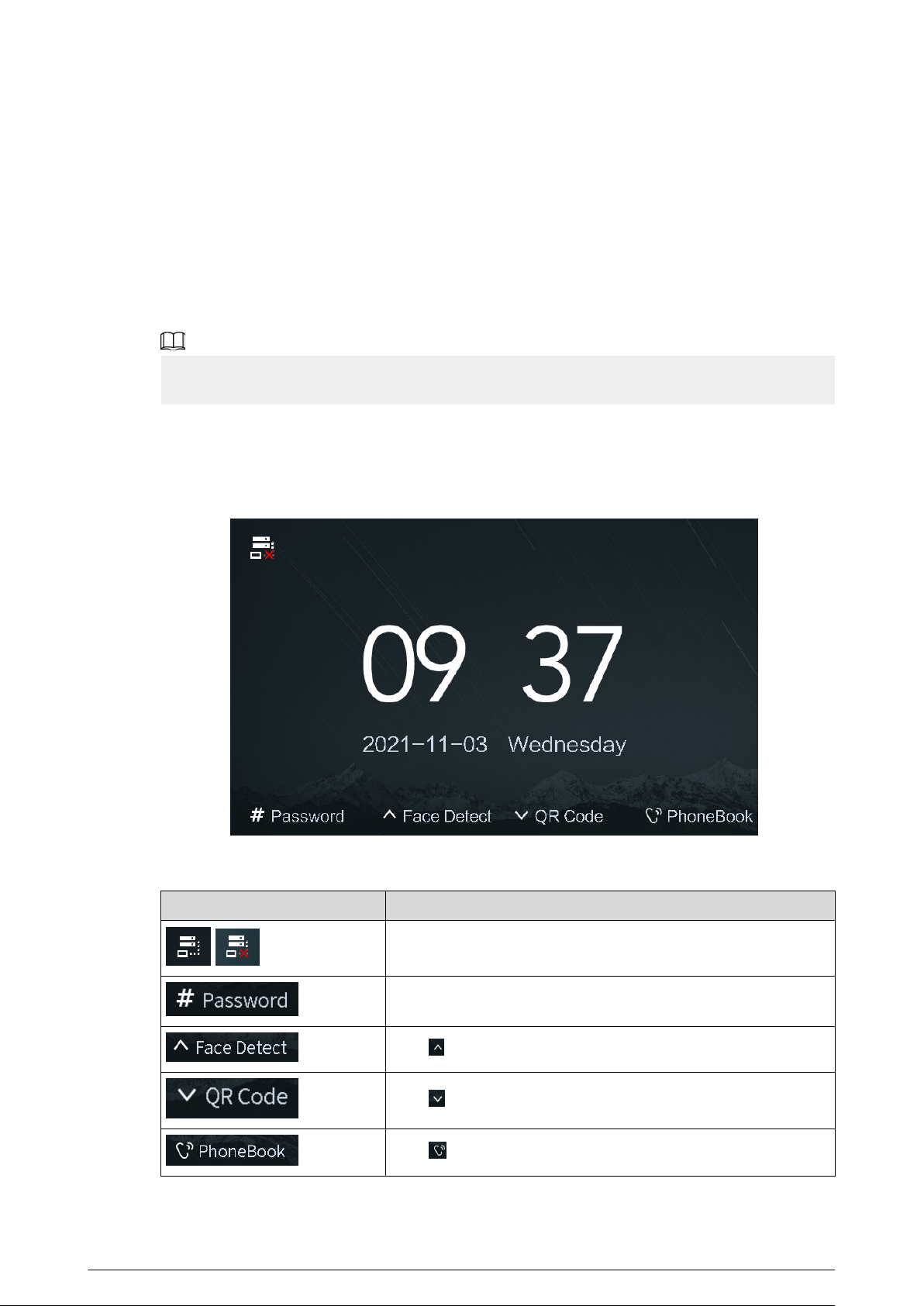
Figure 2-1 Home screen
Table 2-1 Description of the home screen instructions
Instruction
Description
/
Displays the status of the SIP server.
Press #, and then enter the password to open the door.
Press , and the VTO detects the face to open the door.
Press , and then scan the QR code to open the door.
Press to view the phonebook.
12
2.1.2 Engineering Setting
The engineering setting is intended for administrators to make advanced congurations to the
VTO, including issuing access cards, modifying device IP address, and adding person.
Procedure
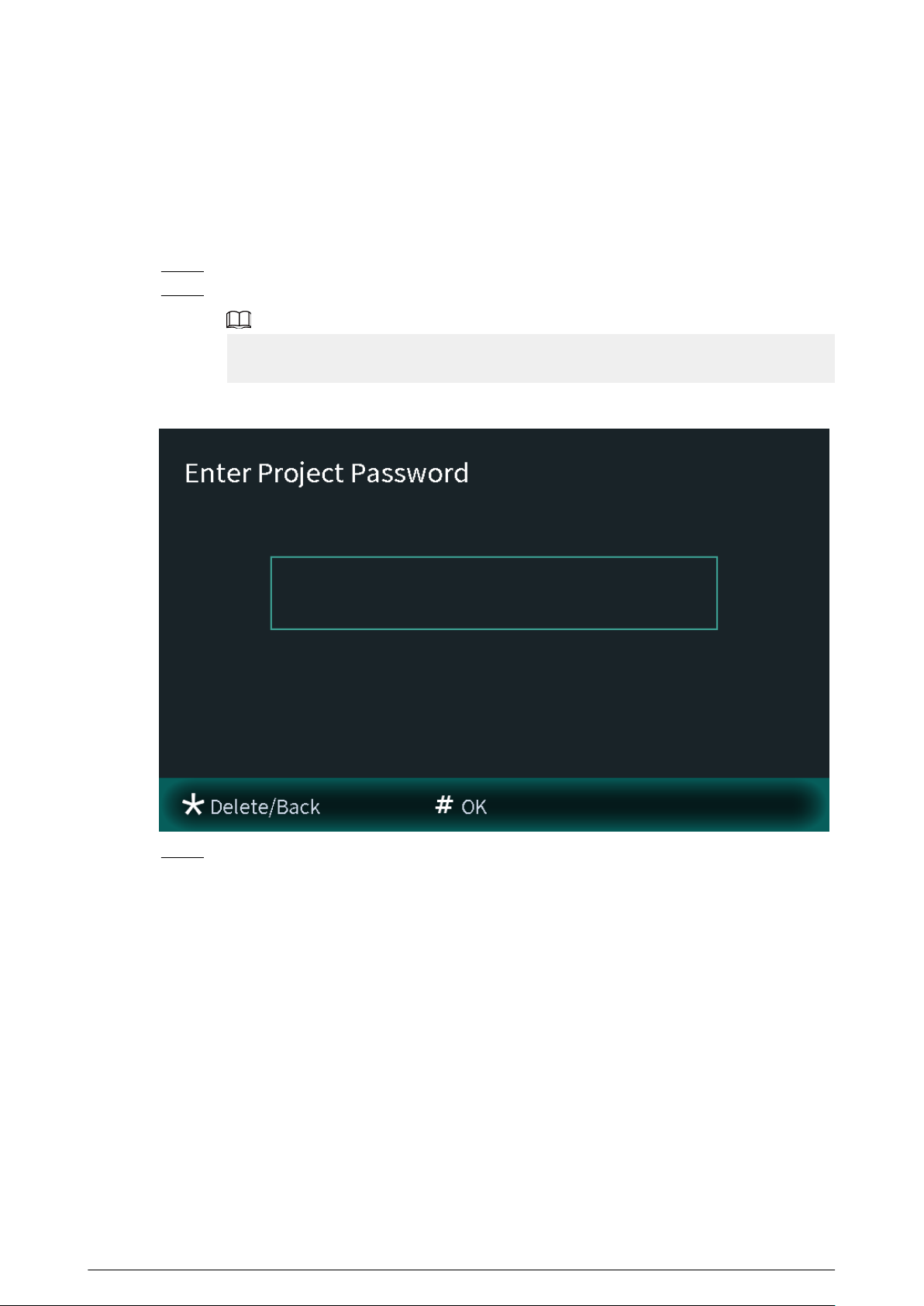
Step 1 Press * on the VTO when the home screen is displayed.
Step 2 Enter the project password.
You need to set the project password by selecting Local Setting > Access Control >
Local on the webpage of the VTO.
Figure 2-2 Enter the password
Step 3 Press # to enter the engineering setting.
13
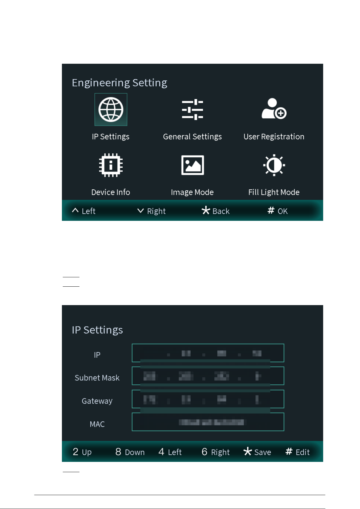
Figure 2-3 Engineering setting
2.1.2.1 Conguring IP Address
Congure the IP address of the VTO.
Procedure
Step 1 Select IP Settings on the Engineering Setting screen.
Step 2 Enter the IP address, subnet mask, and gateway.
Figure 2-4 Congure the IP
Step 3 Press * to complete the settings.
14
2.1.2.2 General Settings
Select General Settings to congure the volume, screensaver time and the brightness time. After
conguration, press * to save and go back to General Settings screen.
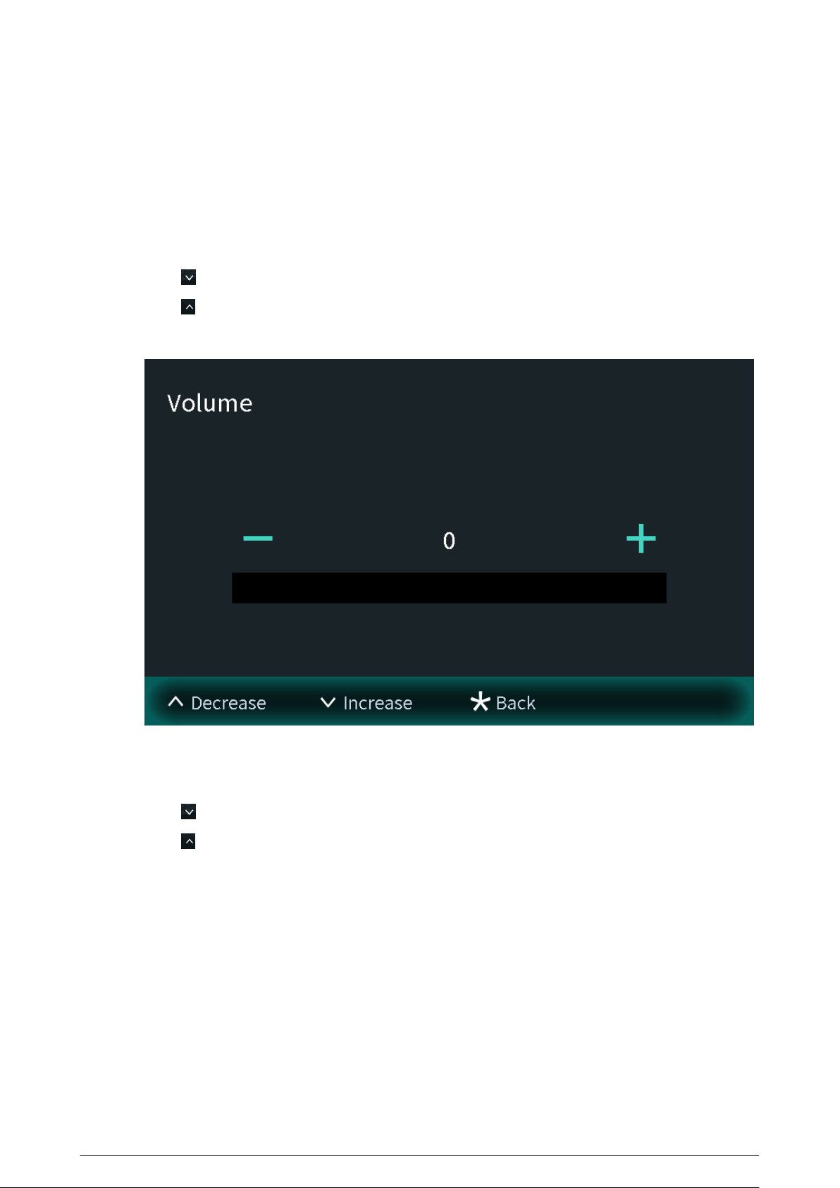
Volume
Press to increase the volume.
Press
to decrease the volume.
Figure 2-5 Conguring the volume
Screensaver time
Press to increase the screensaver time.
Press
to decrease the screensaver time.
15
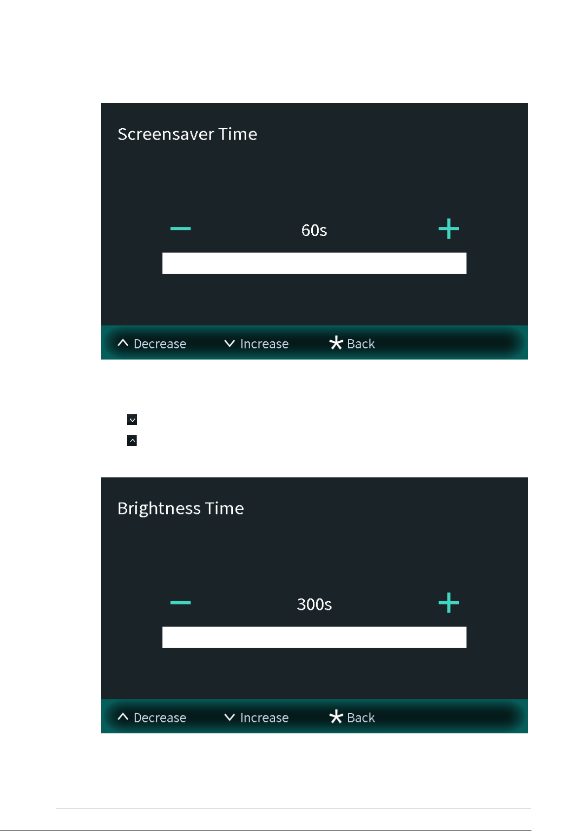
Figure 2-6 Screensaver time
Brightness time
Press to increase the brightness time.
Press to decrease the brightness time.
Figure 2-7 Brightness time
16
2.1.2.3 User Registration
You need to register users to unlock doors. Unlocking methods include card, face, ngerprint, QR
code and password. You can add unlocking methods after conguring personnel information.
●
If the current VTO or another VTO works as the SIP server, register the user on the VTO.
●
If the platform works as the SIP server, the platform sends the information of face images,
ngerprints and cards to the VTO.
The unlocking methods might dier depending on the actual products. Some methods are
available in select models.
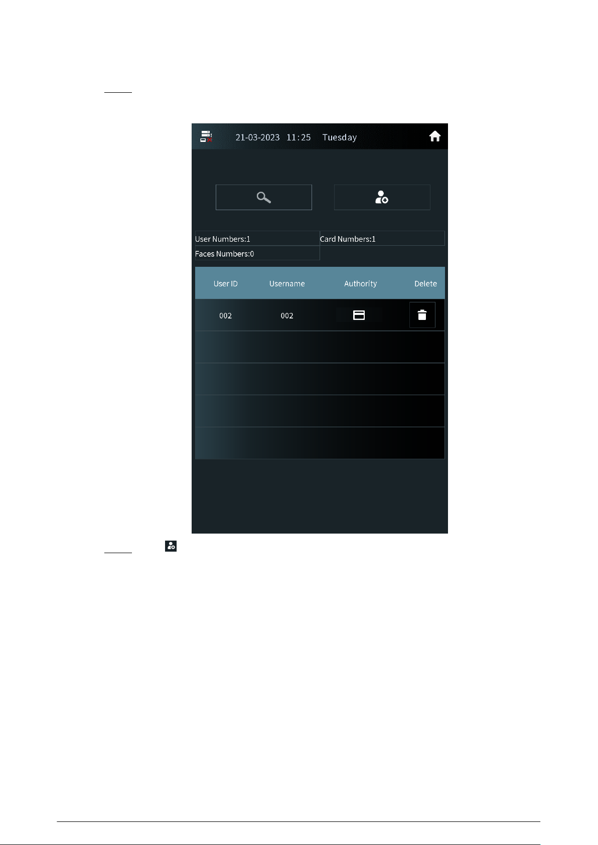
2.1.2.3.1 Adding the User
Basic information includes personnel number, room number and username.
Procedure
Step 1 Select User Registration on the Engineering Setting screen.
Figure 2-8 User registration
Step 2
Press to add the user.
17
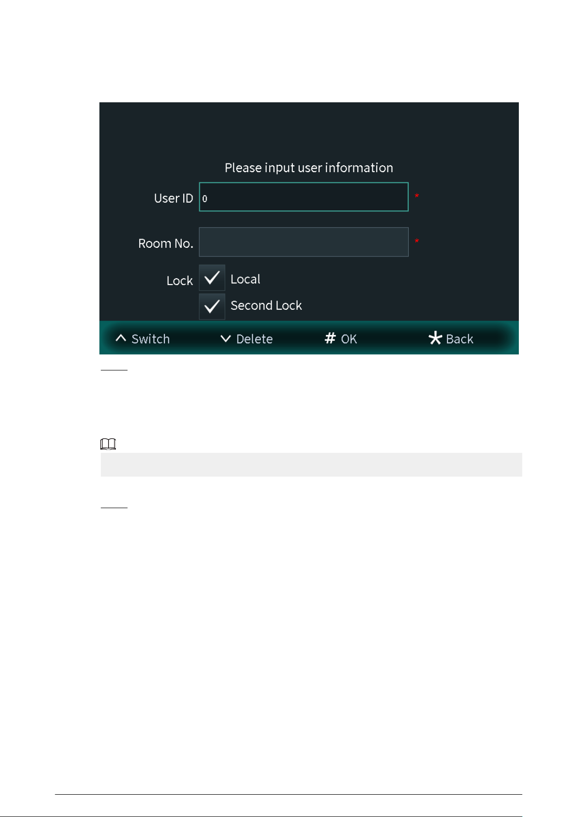
Figure 2-9 Add the user
Step 3 Enter the user ID and room number, congure the locks and then press # to save the
information.
2.1.2.3.2 Adding Faces
Add faces of registered users to unlock the door.
Recognition of the face is available in select models.
Procedure
Step 1 Select Face entry on the User Registration screen.
18
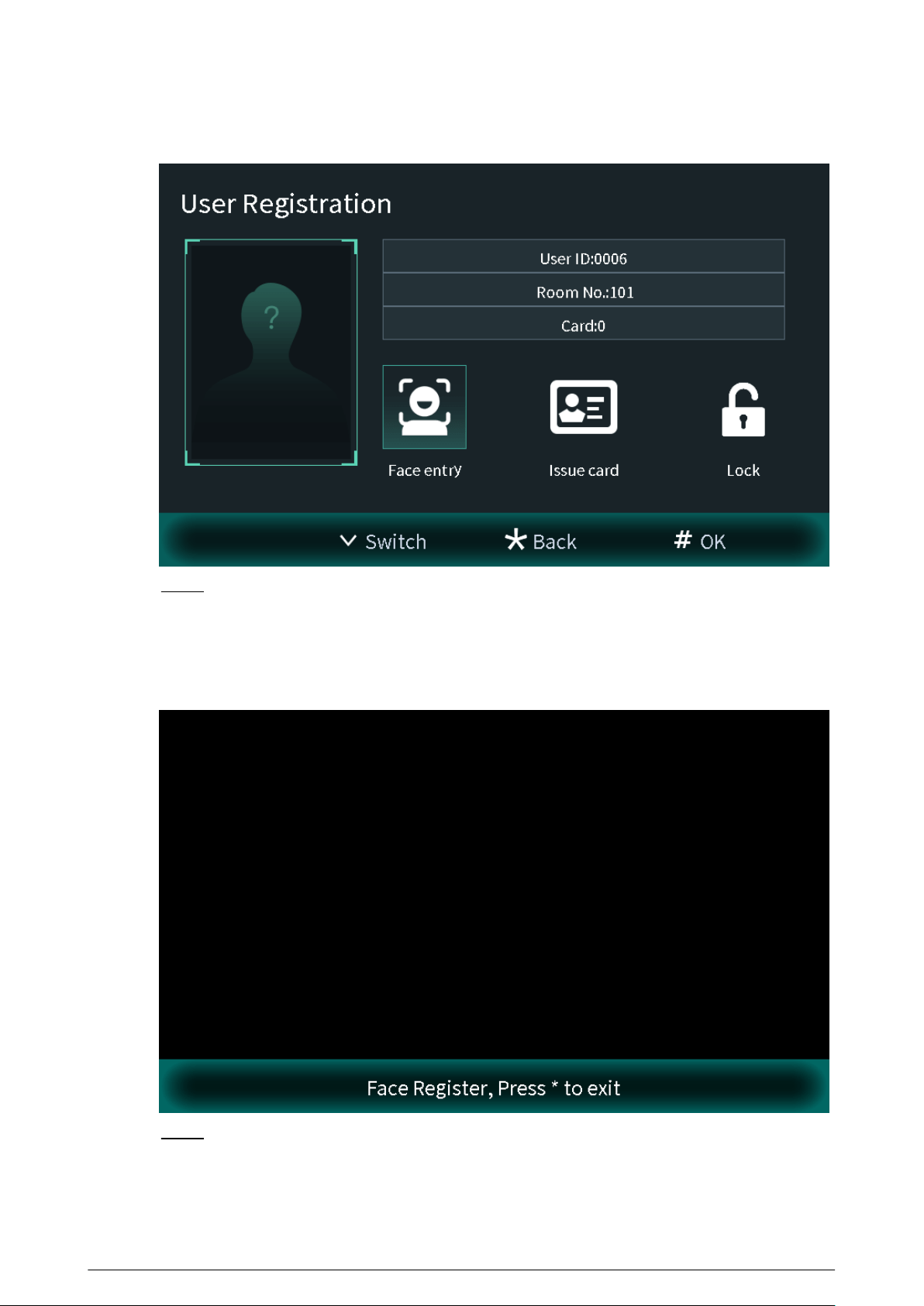
Figure 2-10 Face entry
Step 2 Position your face in the middle of the frame, and the face image will be automatically
taken.
The face image will be automatically taken. If you are not satised with the image, press *
to cancel the photo.
Figure 2-11 Face register
Step 3 Press# to save the photo.
19
2.1.2.3.3 Issuing Cards
You can issue up to 5 cards for each user.
Procedure
Step 1 Select Issue card on the User Registration screen, and then press # to add the card.
Figure 2-12 Card information
Step 2 Select Main card or password to issue cards.
1. Select Main Card if you want to issue cards through the main card, and then swipe
your main card on the card reader to continue the card issuing process.
If you do not have a main card, issue a card on the VTO through password. Then go to
the webpage of the VTO, select Household Setting > Personnel Management , and
click , and then set a card as your main card by clicking .
20
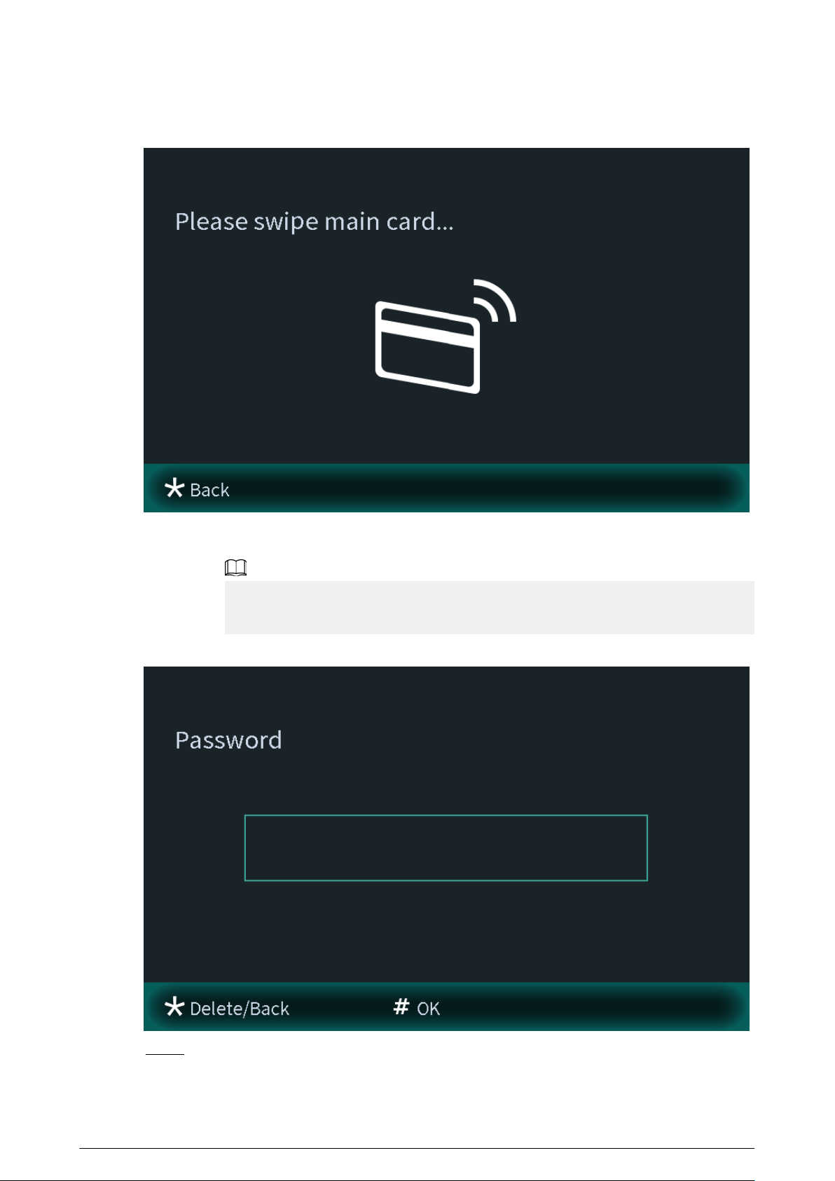
Figure 2-13 Swiping the main card
2. Select Password if you want to issue cards through the password. Enter the password,
and then press #.
You need to enter the password in Issue Card Password textbox that you planned on
the webpage of the VTO through Local Setting > Access Control > Local .
Figure 2-14 Main card password
Step 3 Swipe cards on the card reader, and card numbers will be automatically recognized.
21
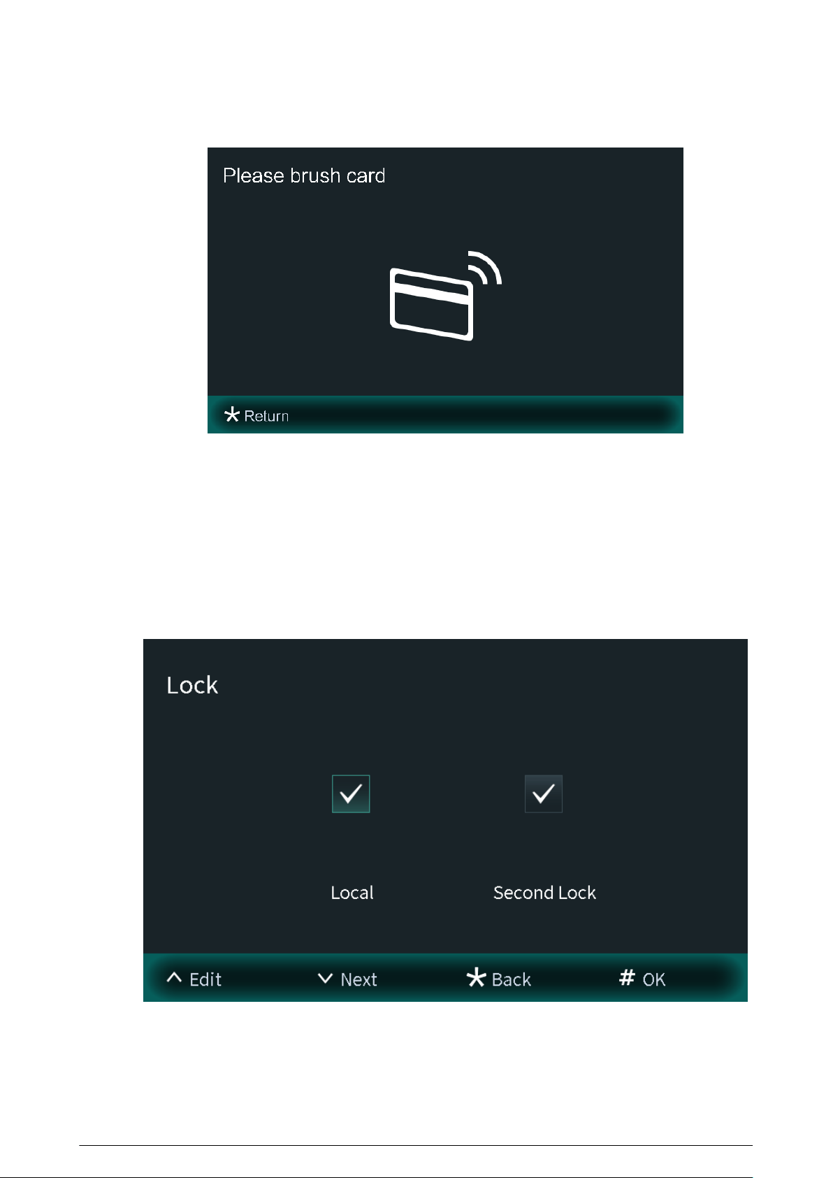
Figure 2-15 New card registration
2.1.2.3.4 Conguring the Locks
Select Lock on the User Registration screen to congure the authority for opening the local lock
and the second lock.
●
Select Local, and the user will have authority to open the local lock.
●
Select Second Lock, and the user will have authority to open the second lock that connects to
the VTO through the function port.
Figure 2-16 Lock
22
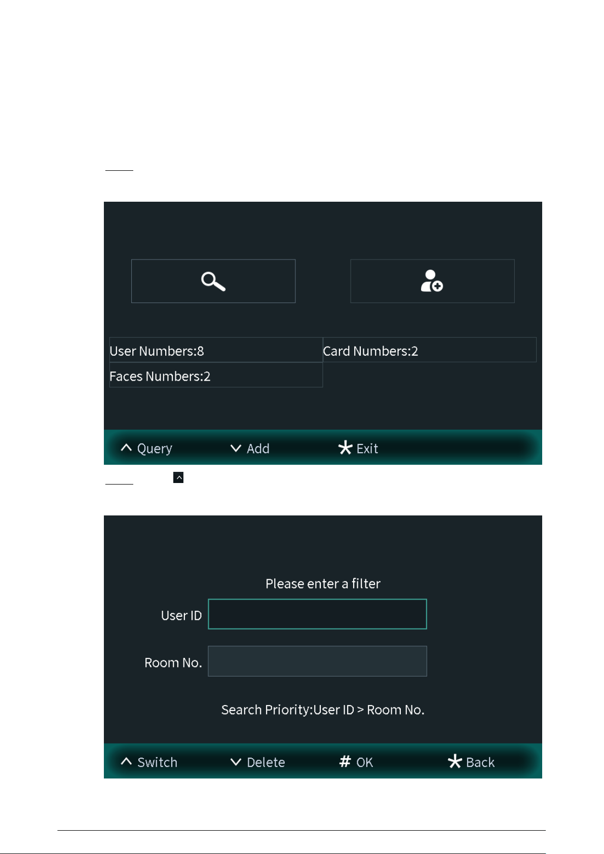
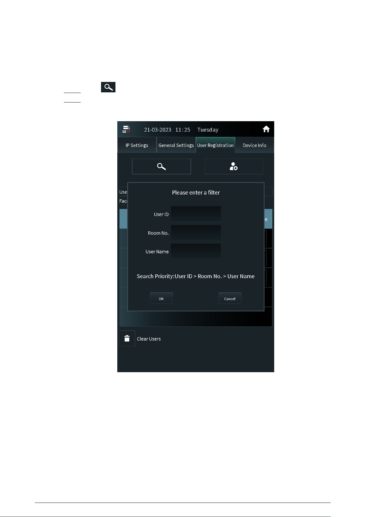
2.1.2.3.5 Searching for the User
View the user information according to the user ID number or the room number. You can congure
the user information.
Procedure
Step 1 Select User Registration on the Engineering Setting screen.
Figure 2-17 User registration
Step 2 Press , and then enter the user ID number or the room number.
Figure 2-18 Searching for the user
23
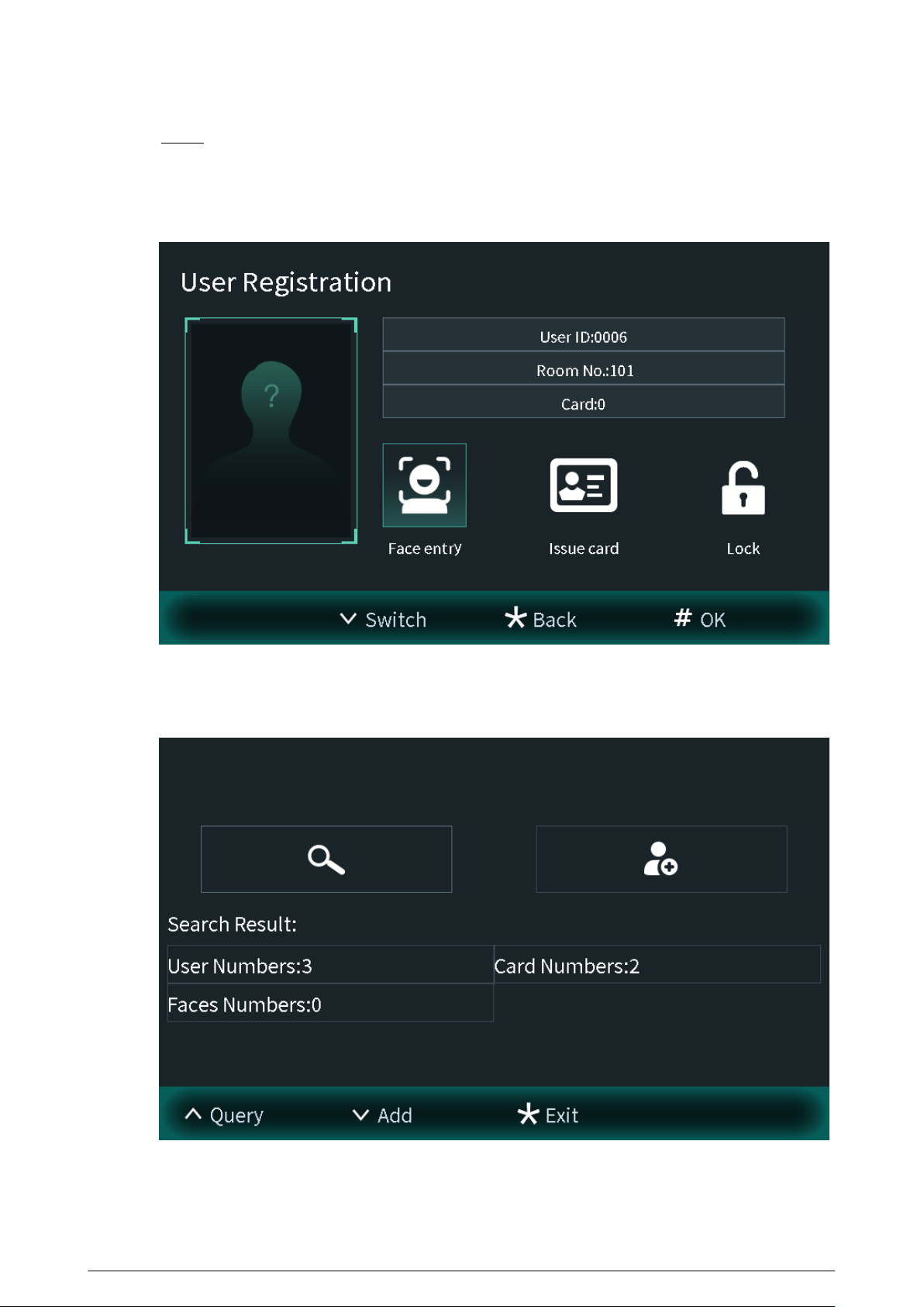
Step 3 Press # to view the user information.
●
Enter the user ID number to view the user information. You can also congure the face
images, cards and locks.
Figure 2-19 User information
●
Enter the room number to view the user numbers, card numbers and face image
numbers of the room.
Figure 2-20 Search result
24
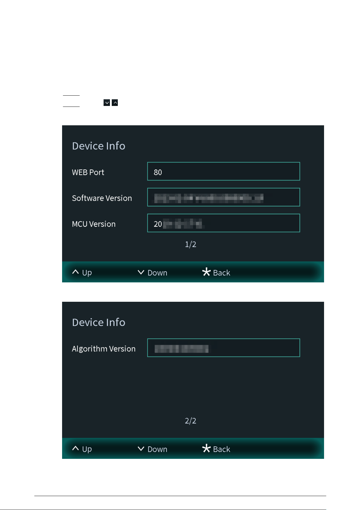
2.1.2.4 Viewing Device Information
You can view the web port number, software version, MCU version and the algorithm version.
Procedure
Step 1 Select Device Info on the Engineering Setting screen.
Step 2 Press / to switch the pages.
Figure 2-21 Device information (1)
Figure 2-22 Device information (2)
25
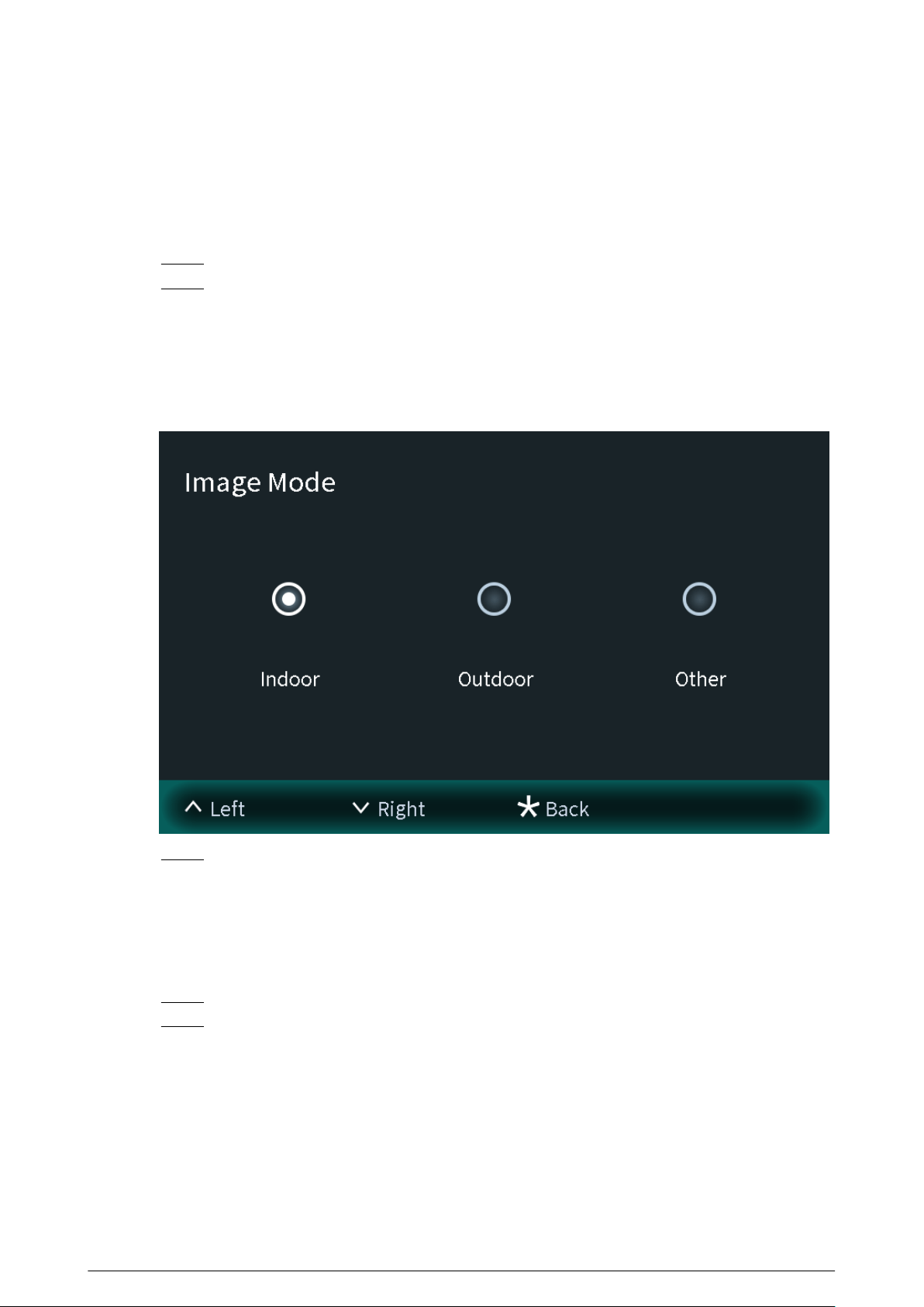
2.1.2.5 Conguring Image Mode
Congure the image mode according to your actual situation. Dierent image modes have
dierent values of image parameters for the actual situation.
Procedure
Step 1 Select Image Mode on the Engineering Setting screen.
Step 2 Select from Indoor , Outdoor and Other.
●
Select the indoor mode when you install the device in the indoor scene.
●
Select the outdoor mode when you install the device in the outdoor scene.
●
Select the other mode when you install the device in the backlight scene, such as the
hallway.
Figure 2-23 Image mode
Step 3 Press * to save and go back to Engineering Setting screen.
2.1.2.6 Conguring Fill Light Mode
Congure the ll light mode to change the illuminator status according to your actual situation.
Procedure
Step 1 Select Fill Light Mode on the Engineering Setting screen.
Step 2 Select from Normal Mode and Night Mode.
●
Normal mode: When the device detects the people, the illuminator is switched on.
When there are no people, the illuminator is automatically switched o.
●
Night mode: Select the night mode especially in the night. The illuminator will be
always on.
26
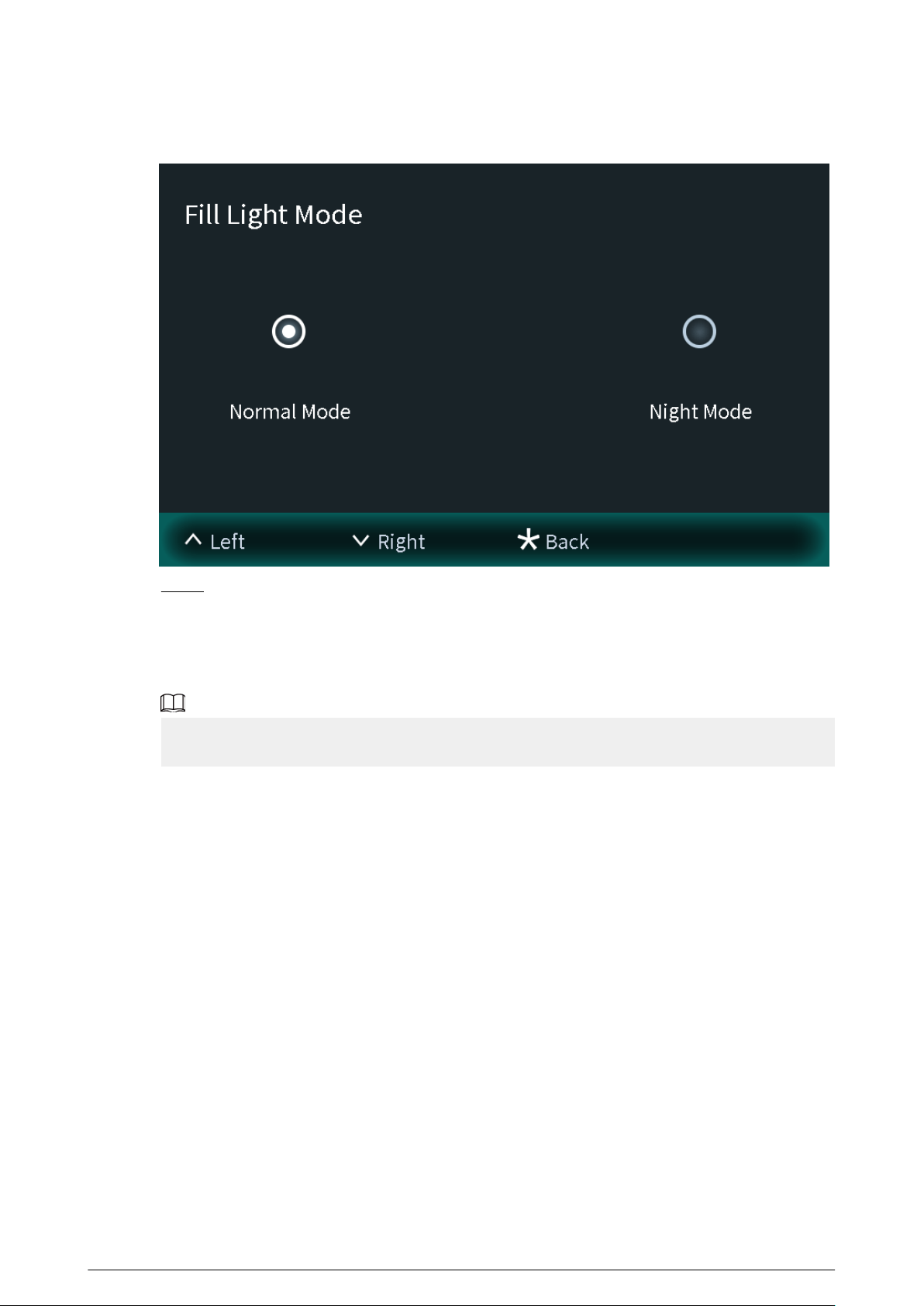
Figure 2-24 Fill light mode
Step 3 Press * to save and go to Engineering Setting screen.
2.2 75/95 Series
The 75 series and 95 series devices use the following screen style.
The following snapshots of the devices are for reference only, and slight dierences might be found
in the operation screen of the VTO, depending on your model.
27
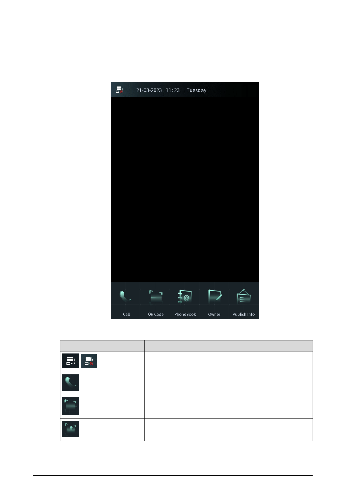
2.2.1 Home Screen
Figure 2-25 Home screen
Table 2-2 Description of home screen instructions
Instruction
Description
/
Displays the status of the SIP server.
Call or enter the password to go to the screen of the engineer
setting.
Scan the QR code to open the door.
Recognize the face to open the door.
28

Instruction Description
View the phonebook.
Register the owner information.
View the published information.
2.2.2 Engineering Setting
Background Information
●
Congure the project password through Local Setting > Access Control > Local on the
webpage.
●
Only the administrator or the engineer can operate on the engineering setting screen.
Procedure
Step 1 Power on the VTO.
Step 2 Tap on the home screen.
Step 3 Enter the password to go to the screen of the engineering setting.
The password is *+project password+#. For example, if you congure the project
password as 888888 on the webpage, enter *888888# to go to the screen of the
engineering setting.
29
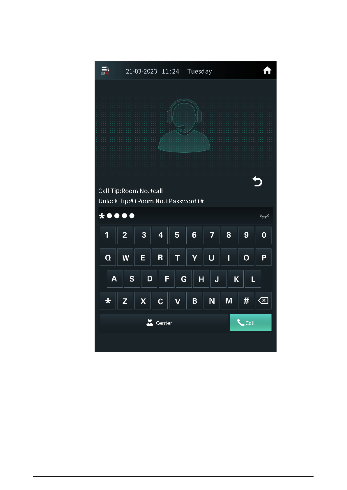
Figure 2-26 Enter the password
2.2.2.1 Conguring the IP Address
Congure the IP address of the VTO according to your actual network plan.
Procedure
Step 1 Press IP Settings on the screen of the engineer setting.
Step 2 Enter the IP address, subnet mask and the gateway.
30
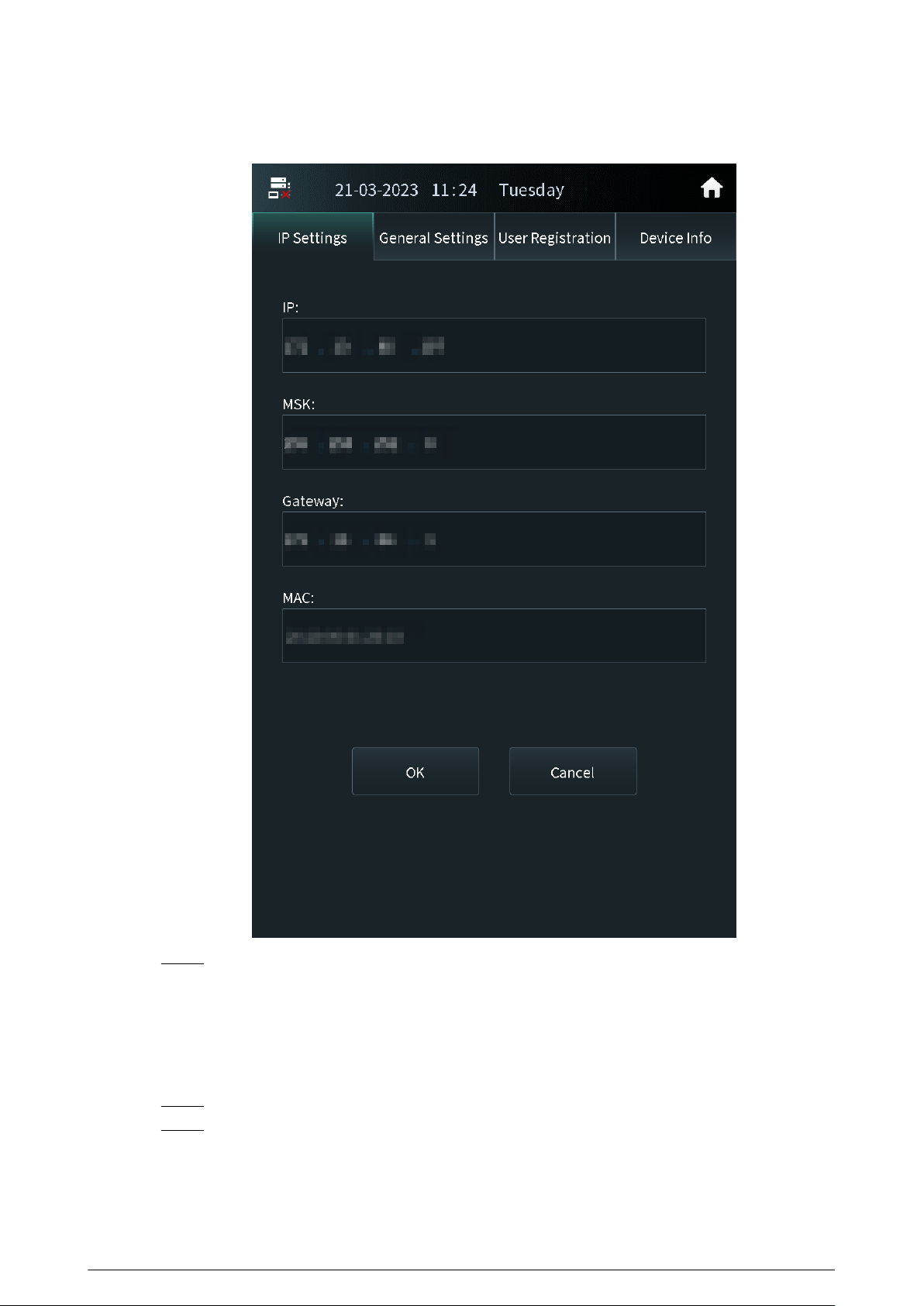
Figure 2-27 IP settings
Step 3 Press OK.
2.2.2.2 General Settings
Congure the volume, brightness time and other parameters.
Procedure
Step 1 Press General Settings on the screen of the engineer setting.
Step 2 Press + or – to adjust the volume, screensaver time and the brightness time.
●
Volume: The volume of operating the VTO or calling of the VTO.
●
Screensaver time: The amount of idle time that must elapse before the screensaver is
activated.
31
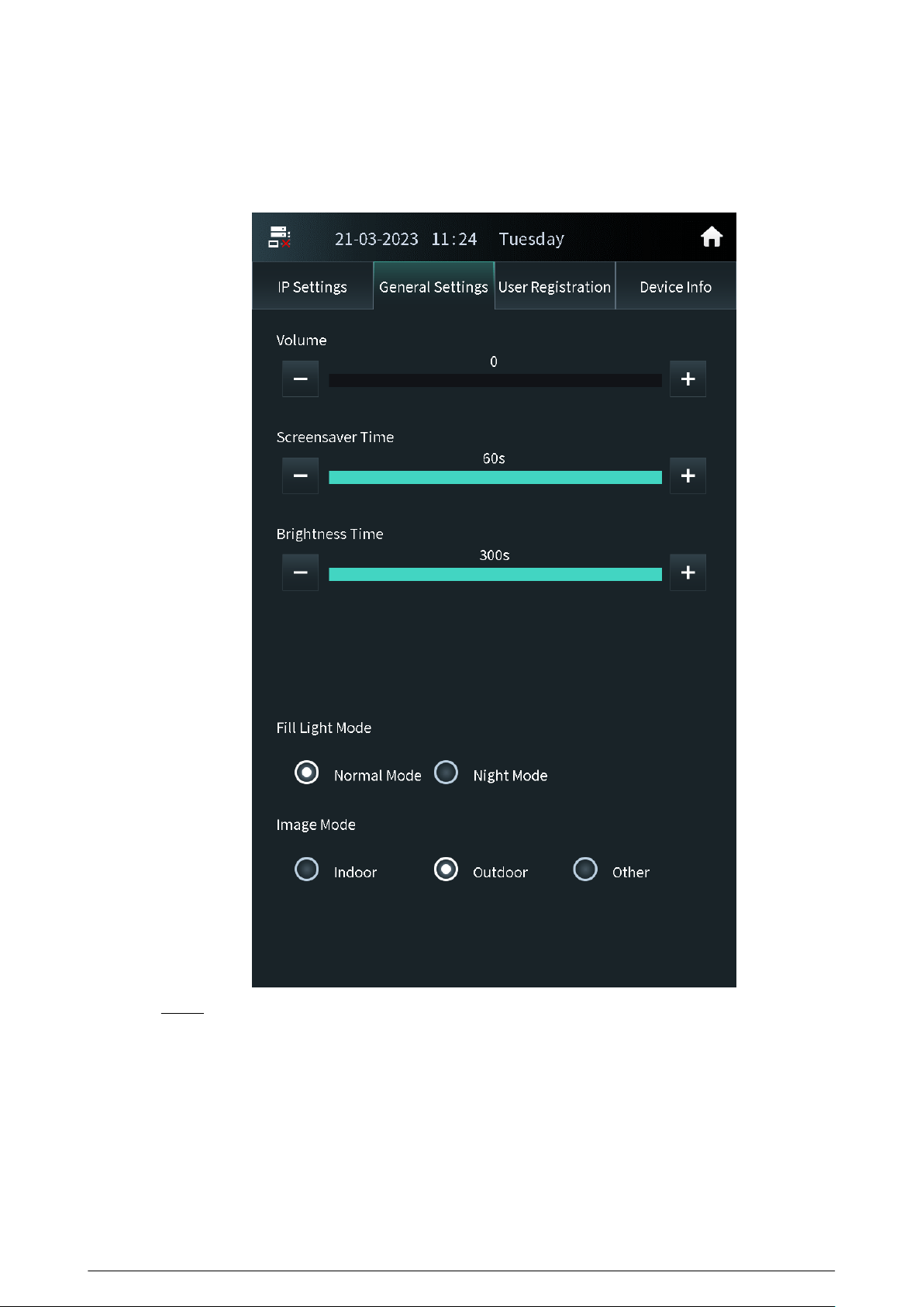
●
Brightness time: The screen display turns o automatically after you leave the VTO idle
for the time you congure.
Figure 2-28 General settings
Step 3 Congure the ll light mode and the image mode.
Other in the image mode means other backlight scenes such as the hallway or the semi-
outdoor.
2.2.2.3 User Registration
If the current VTO or another VTO works as the SIP server, the administrator can register user
information and add faces, ngerprints and cards. The VTO also supports conguring the main card
and reporting the loss of the card.
32
●
The faces, ngerprints and cards that are registered are only valid to the current VTO.
●
If the platform works as the SIP server, the platform sends the faces, ngerprints and cards
information to the VTO.
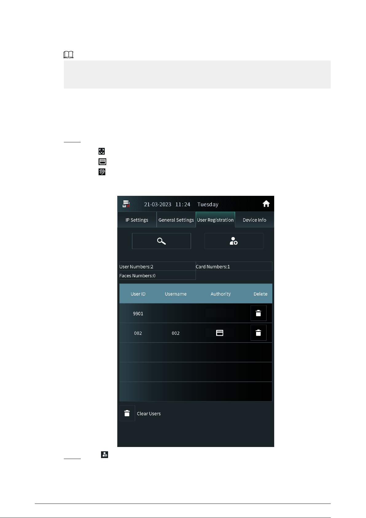
2.2.2.3.1 Adding Users
Add the user, and then register the information on the face, ngerprint and the card.
Procedure
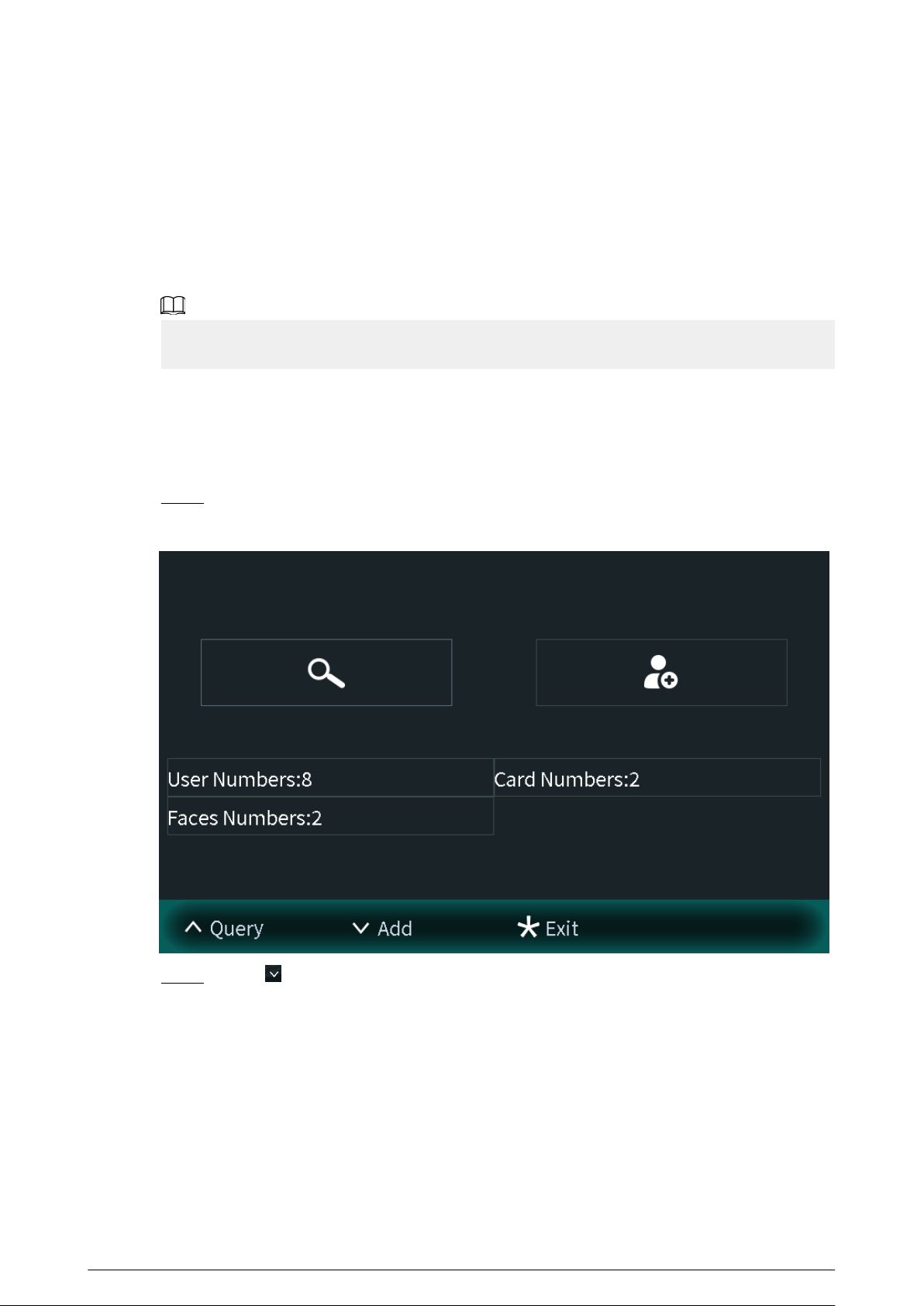
Step 1 Tap User Registration on the screen of the engineer setting.
●
: The user has registered the face.
●
: The user has registered the card.
●
: The user has registered the ngerprint.
Figure 2-29 User registration
Step 2
Tap , enter the user ID, room number and the user name, and then congure the local
lock and the second lock.
33
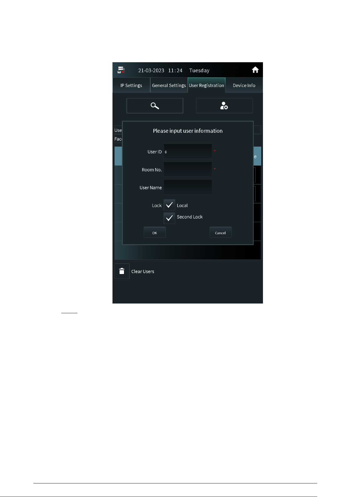
Figure 2-30 Add the user
Step 3 Tap OK.
34
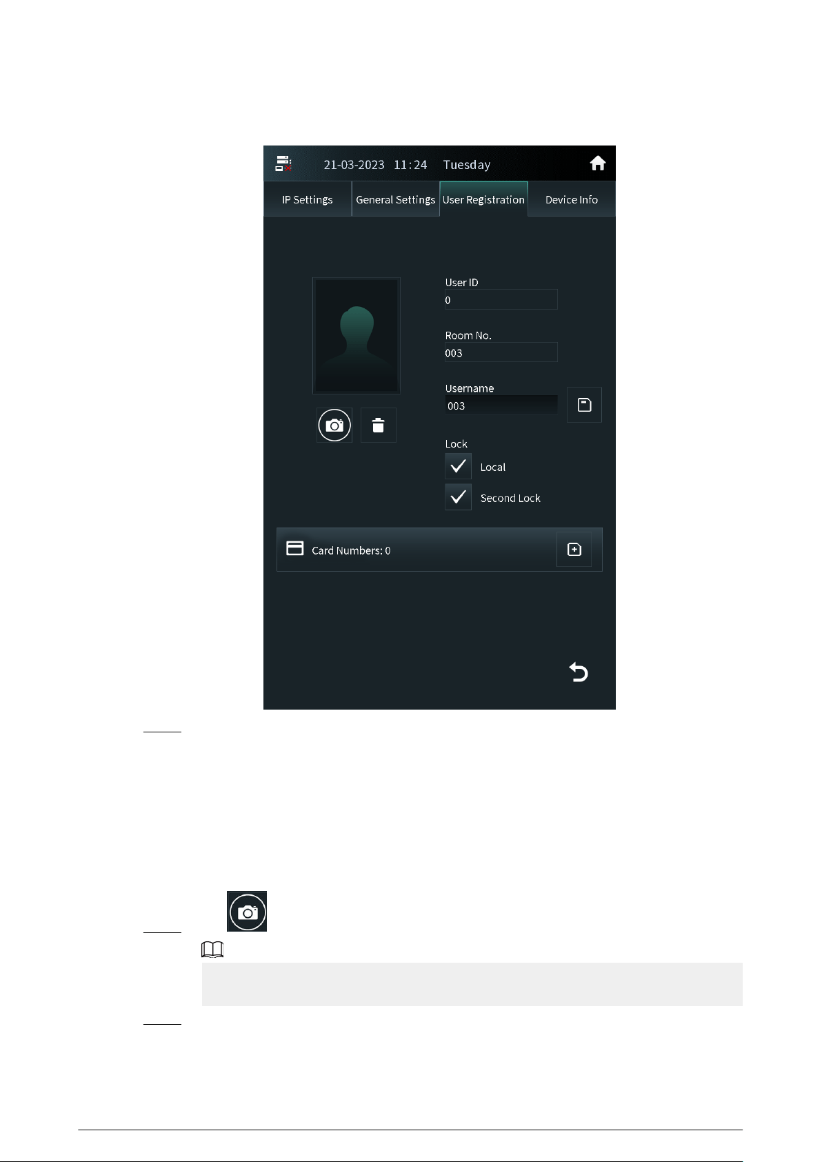
Figure 2-31 User information
Step 4 Add the face, ngerprint and the card.
●
For details about adding the face image, see “2.2.2.3.2 Adding Faces”.
●
For details about adding the ngerprint, see “2.2.2.3.3 Adding Fingerprints”.
●
For details about adding the card, see “2.2.2.3.4 Issuing Cards”.
2.2.2.3.2 Adding Faces
Procedure
Step 1 Tap on the screen of the user information.
If you are on the user registration screen, select the user to go to the user information
screen.
Step 2 Make sure that your face is in the middle of the frame, and the face image will be
automatically taken.
Tap Cancel to register again if you do not want the photo.
35
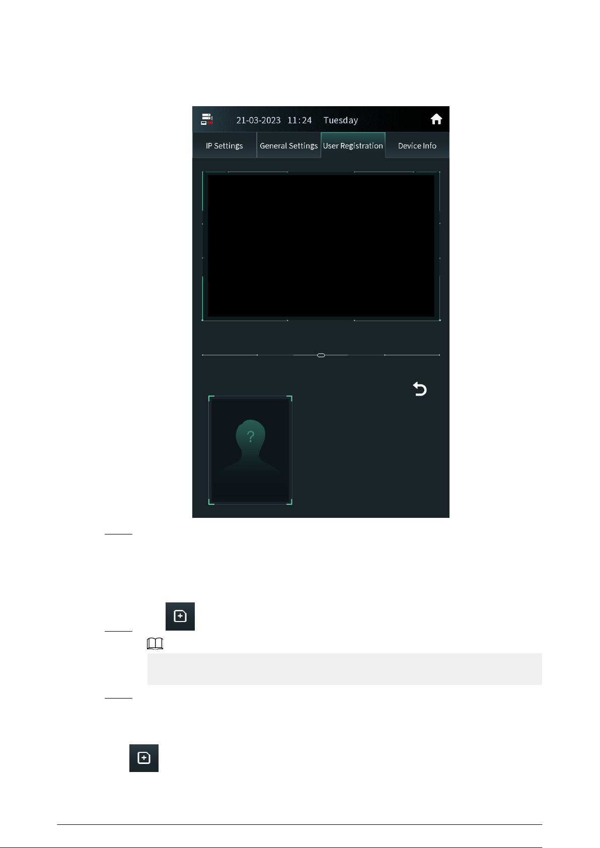
Figure 2-32 Face register
Step 3 Tap OK after you conrm the face image.
2.2.2.3.3 Adding Fingerprints
Procedure
Step 1 Tap next to the ngerprint numbers on the screen of the user information.
If you are on the user registration screen, select the user to go to the user information
screen.
Step 2 Press the ngerprint sensor, and then move the nger after the voice or screen prompt.
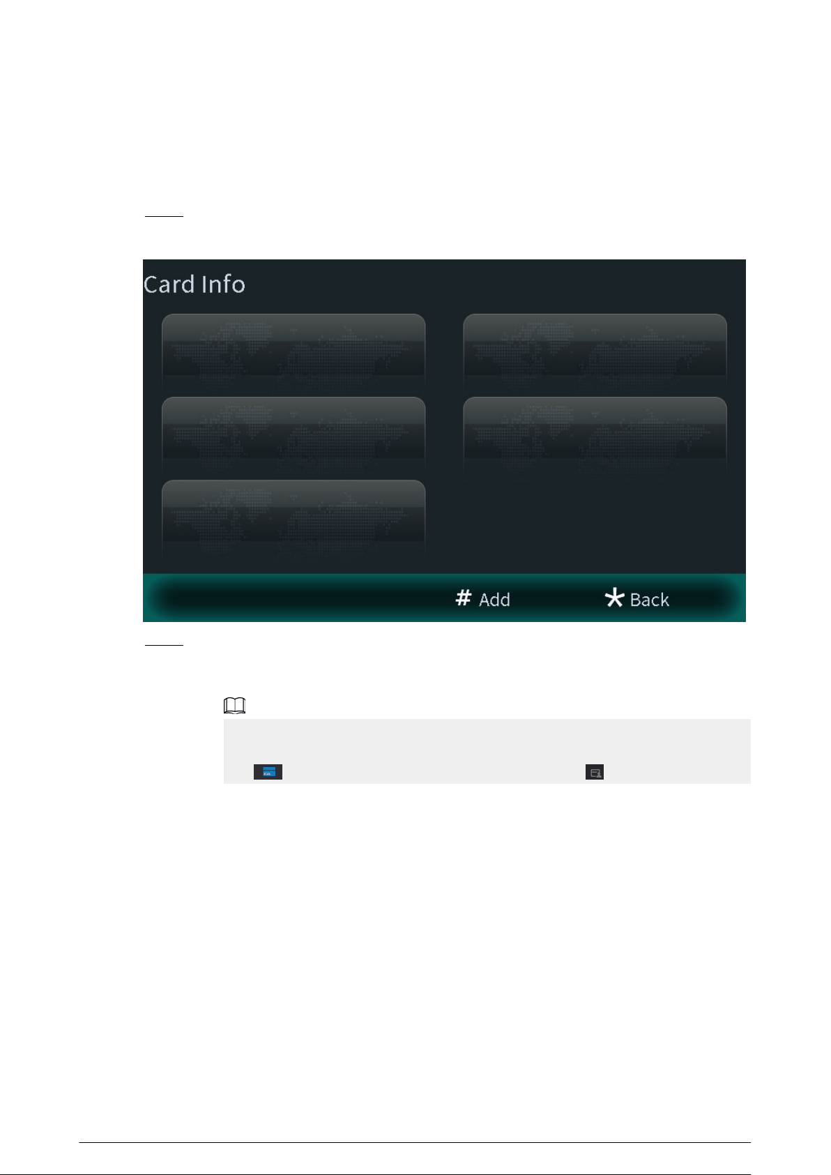
2.2.2.3.4 Issuing Cards
Press next to the card numbers on the screen of the user information.
36
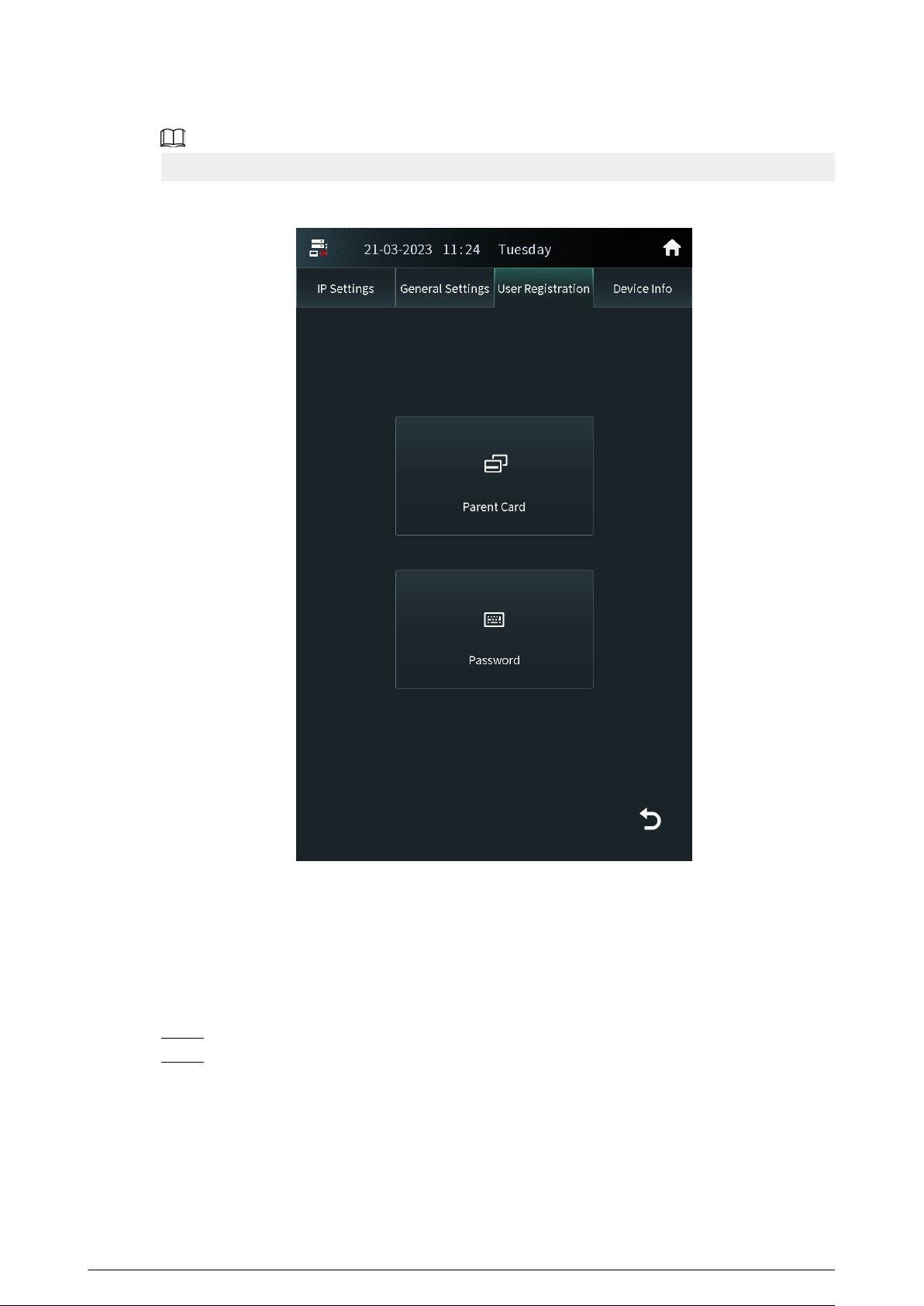
If you are on the user registration screen, select the user to go to the user information screen.
Figure 2-33 Issue cards
Issuing Cards by the Main Card
Use the authorized main card to register the new card.
Prerequisites
Make sure that there is the main card. If there is no main card, register the card by the password,
and then congure the card as the main card.
Procedure
Step 1 Select Parent Card on the issue card screen.
Step 2 Swipe the main card.
37
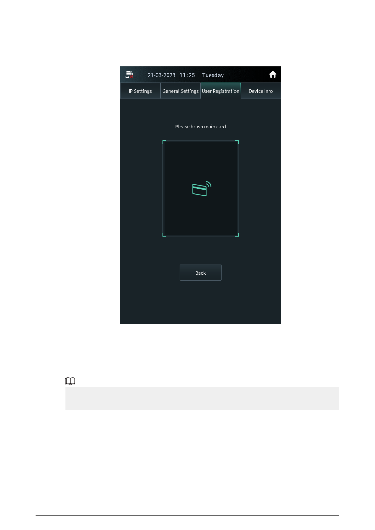
Figure 2-34 Main card
Step 3 Swipe the new card.
The VTO displays Issue Card Success . You can swipe other cards to continuously register.
Tap Back if you do not need to add other cards.
Issuing Cards by the Password
Use the issue card password to register the new card.
You can congure the password through Local Setting > Access Control > Password
Management . For details, see Conguring Local Lock.
Procedure
Step 1 Select Password on the issue card screen.
Step 2 Enter the issue card password, and then tap OK.
38
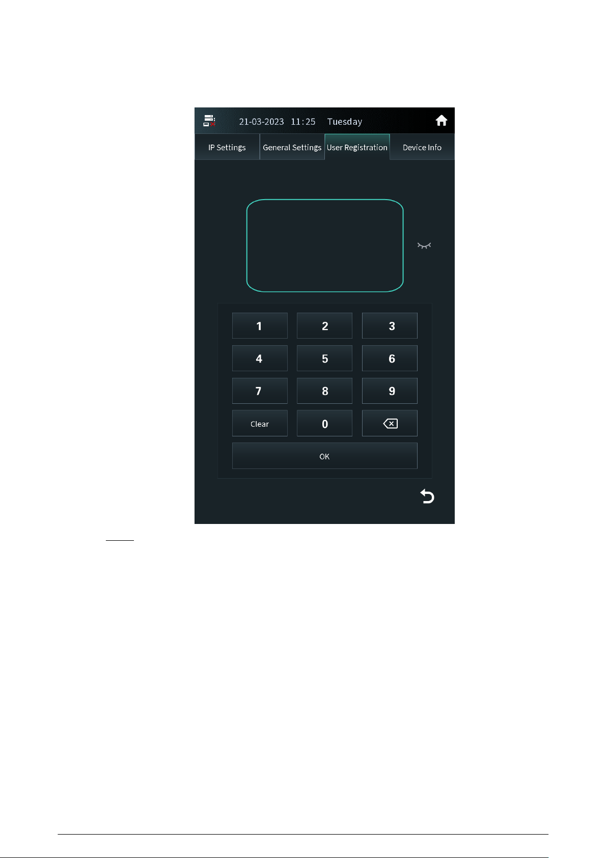
Figure 2-35 Issue card password
Step 3 Swipe the new card.
The VTO displays Issue Card Success . You can swipe other cards to continuously register.
Tap Back if you do not need to add other cards.
39
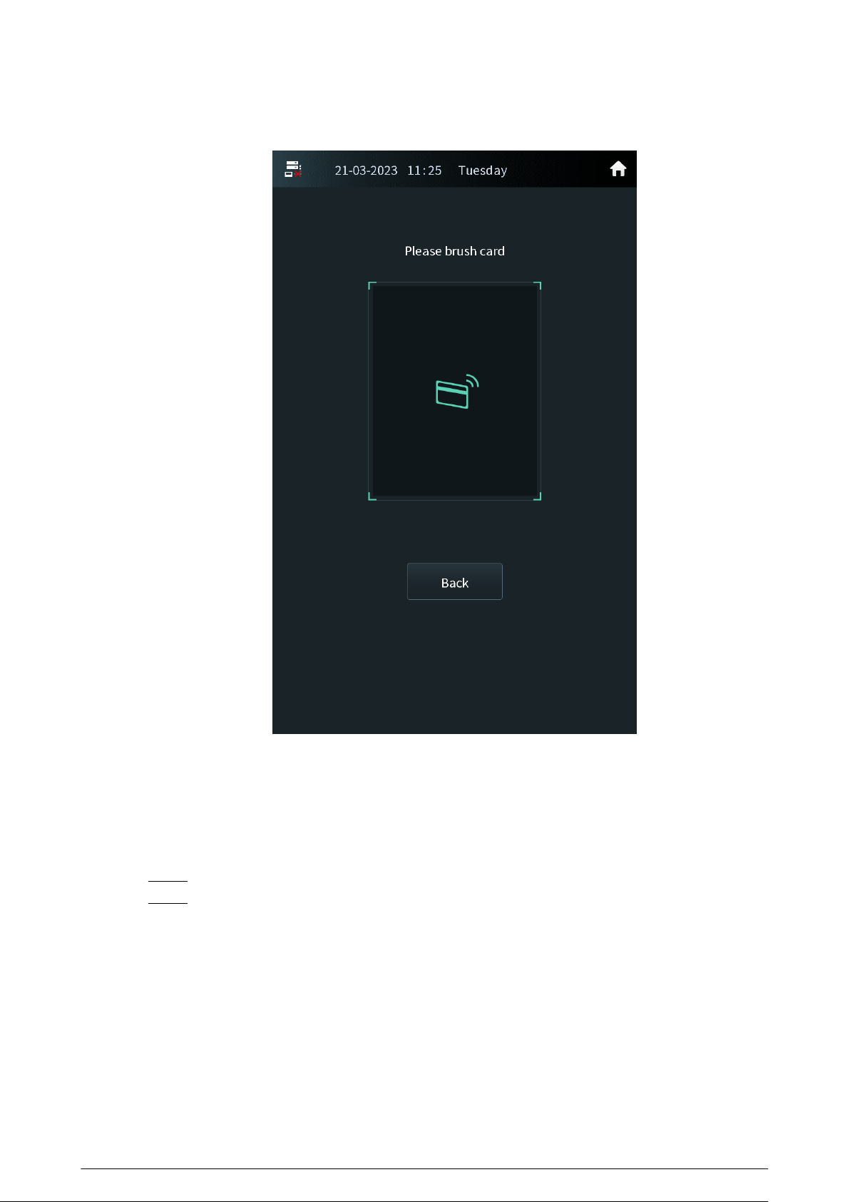
Figure 2-36 New card registration
2.2.2.3.5 Card Management
Conguring the Main Card
The main card is used to register other new cards.
Procedure
Step 1 Select the user on the user registration screen.
Step 2 Press Card Numbers.
40
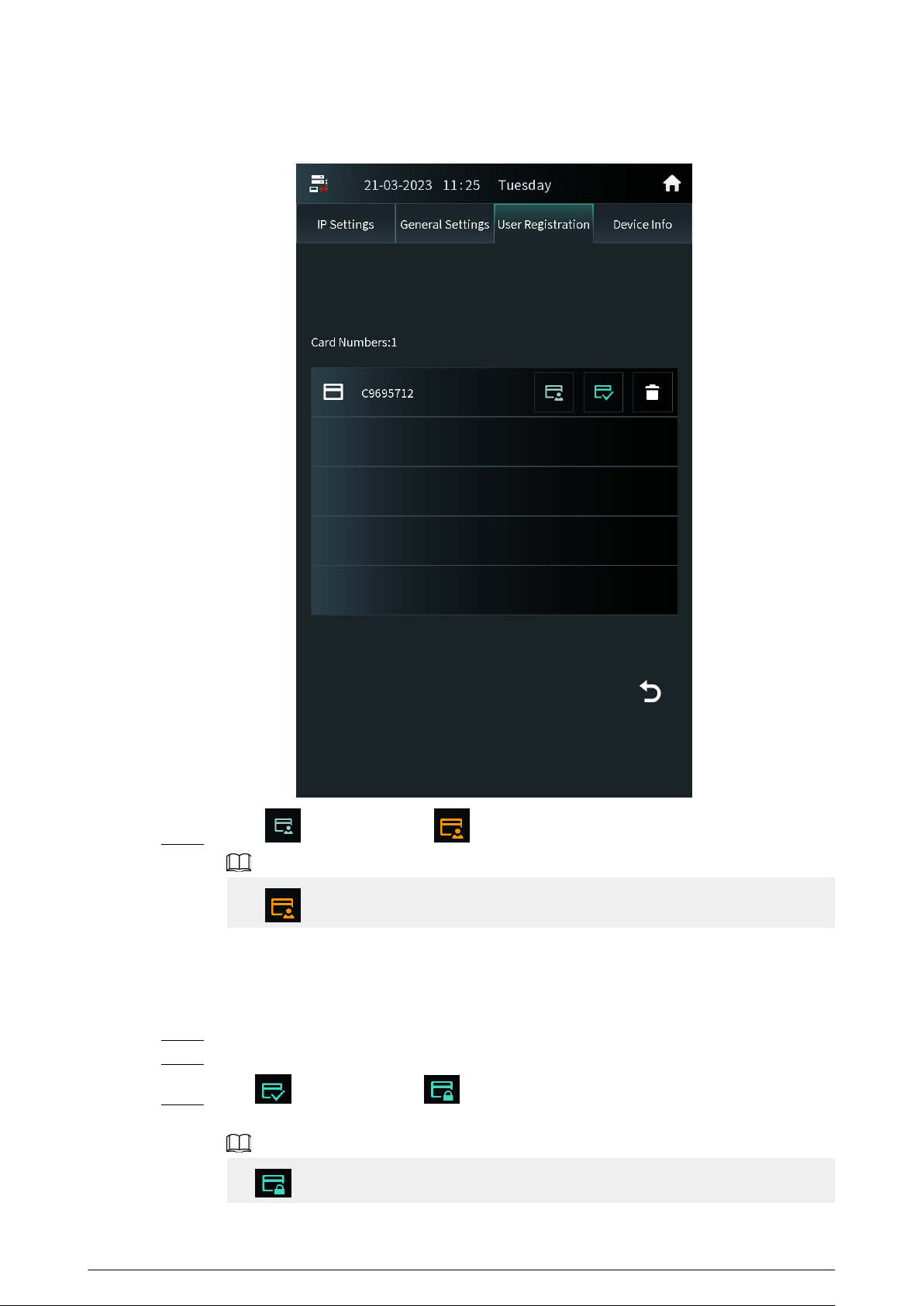
Figure 2-37 Card list
Step 3 Press , and the icon turns . The card is congured as the main card.
Press to cancel the main card.
Reporting the Loss of the Card
If you report the loss of the common card, the card cannot be used to open the door. If you report
the loss of the main card, the main card cannot be used to open the door or register the new card.
Procedure
Step 1 Select the user on the user registration screen.
Step 2 Tap Card Numbers.
Step 3 Tap , and the icon turns . The card is reported the loss and cannot be used to
open the door.
Tap to cancel the report of loss. The card can be used to open the door again.
41
2.2.2.3.6 Searching for a User
Procedure
Step 1 Tap on the user registration screen.
Step 2 Enter the user ID, room number or the user name, and then tap OK.
Figure 2-38 Search for the user
2.2.2.4 Viewing Device Information
Press Device Info on the screen of the engineer setting to view the details on the VTO.
42
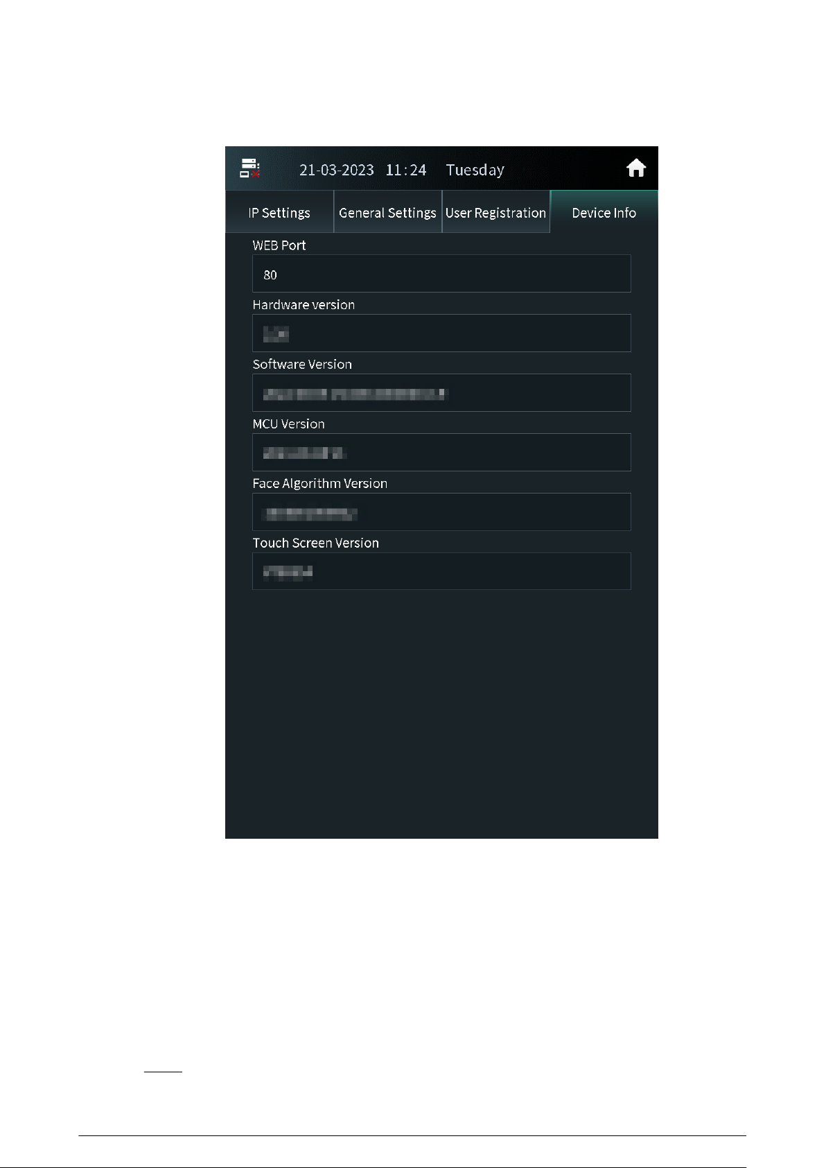
Figure 2-39 View the device information
2.2.3 Owner Registration
The owner can only register and maintain the information, face images and ngerprints of people
to the VTH.
2.2.3.1 Adding Owners
Add the owner, and then register the face and ngerprint.
Procedure
Step 1 Tap Owner on the home screen.
43
Step 2 Swipe the registered card to enter owner list.
Figure 2-40 User list
Step 3 Tap to add the user.
44
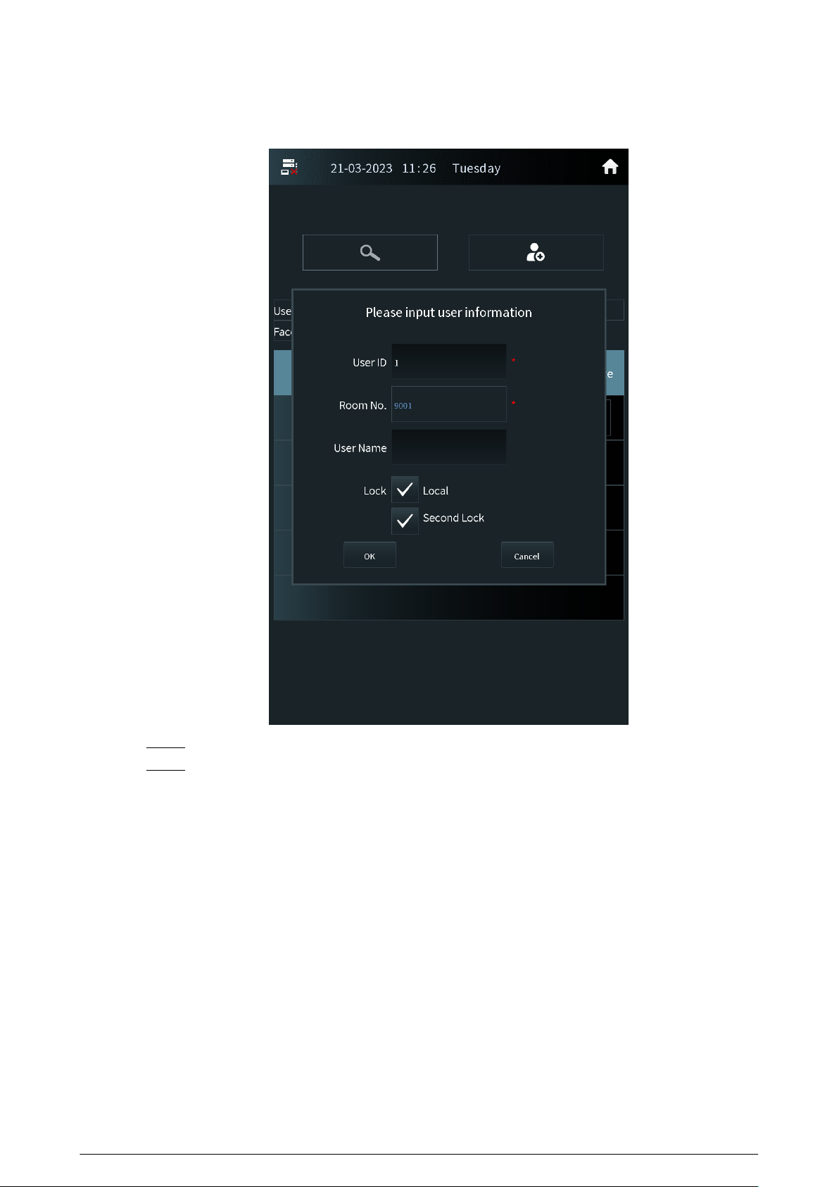
Figure 2-41 Add the user
Step 4 Enter the user ID, room number and the user name.
Step 5 Congure the local lock or the second lock, and then tap OK.
45
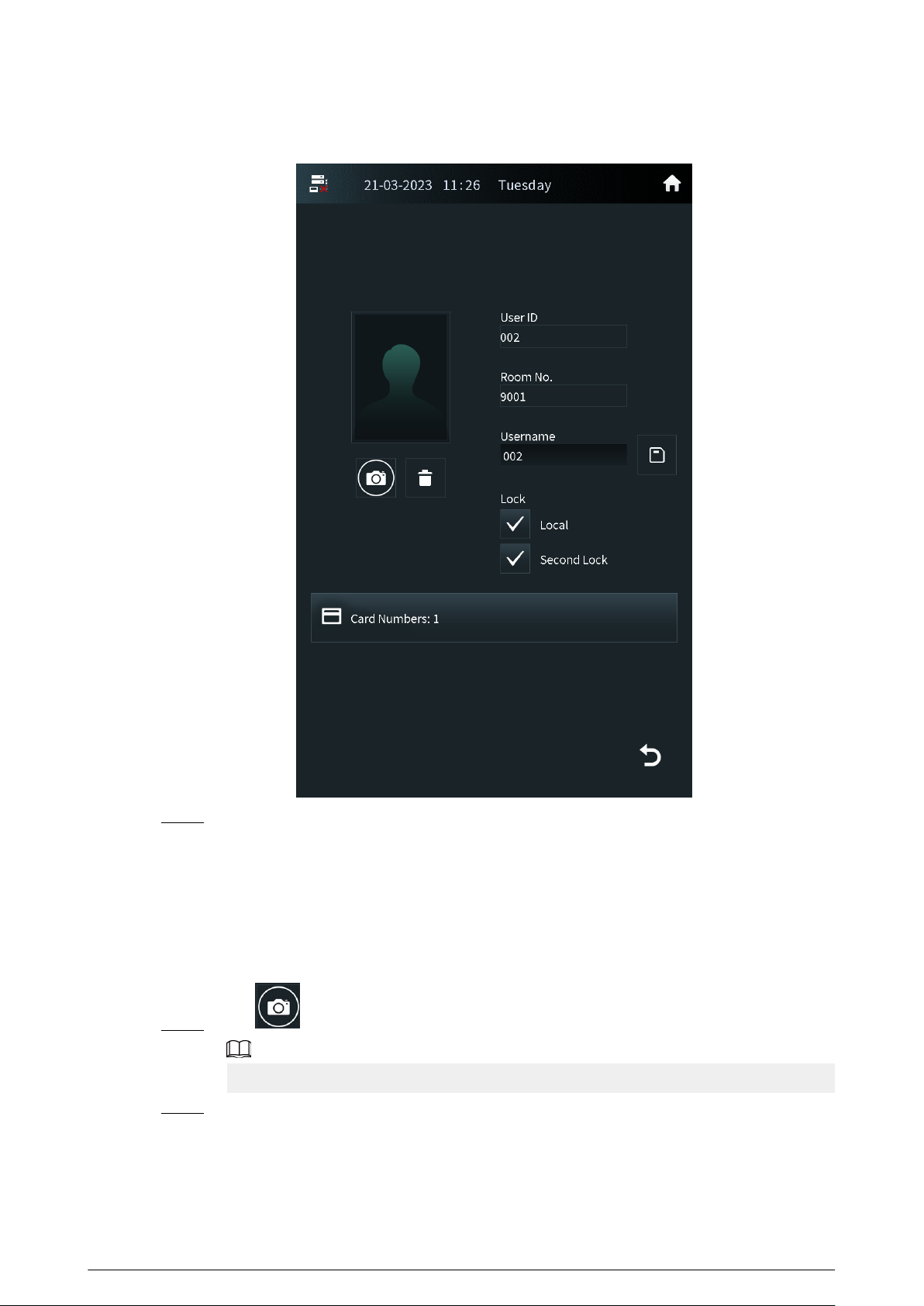
Figure 2-42 User information
Step 6 Register the face image and the ngerprint.
●
For details about adding the face image, see “2.2.3.2 Adding Faces”.
●
For details about adding the ngerprint, see “2.2.3.3 Adding Fingerprints”.
2.2.3.2 Adding Faces
Procedure
Step 1 Tap on the screen of the user information.
If you are on the owner screen, select the user to go to the user information screen.
Step 2 Position your face in the middle of the frame.
The face image will be automatically taken. If you are not satised with the photo, tap
Cancel to cancel the photo and register again.
46

Figure 2-43 Face registration
Step 3 Tap OK after you conrm the face image.
2.2.3.3 Adding Fingerprints
Procedure
Step 1 Tap next to the ngerprint numbers on the screen of the user information.
If you are on the owner screen, select the user to go to the user information screen.
Step 2 Press the ngerprint sensor, and then move the nger after the voice or screen prompt.
2.2.4 Unlock
47
2.2.4.1 Unlocking by Identifying the Face
When people come close to the VTO, the VTO automatically displays face detect screen and detects
the face. The voice prompt and the device prompt Open door success means that the door opens
and you can enter. If the device displays Unauthorized, register the face rst.
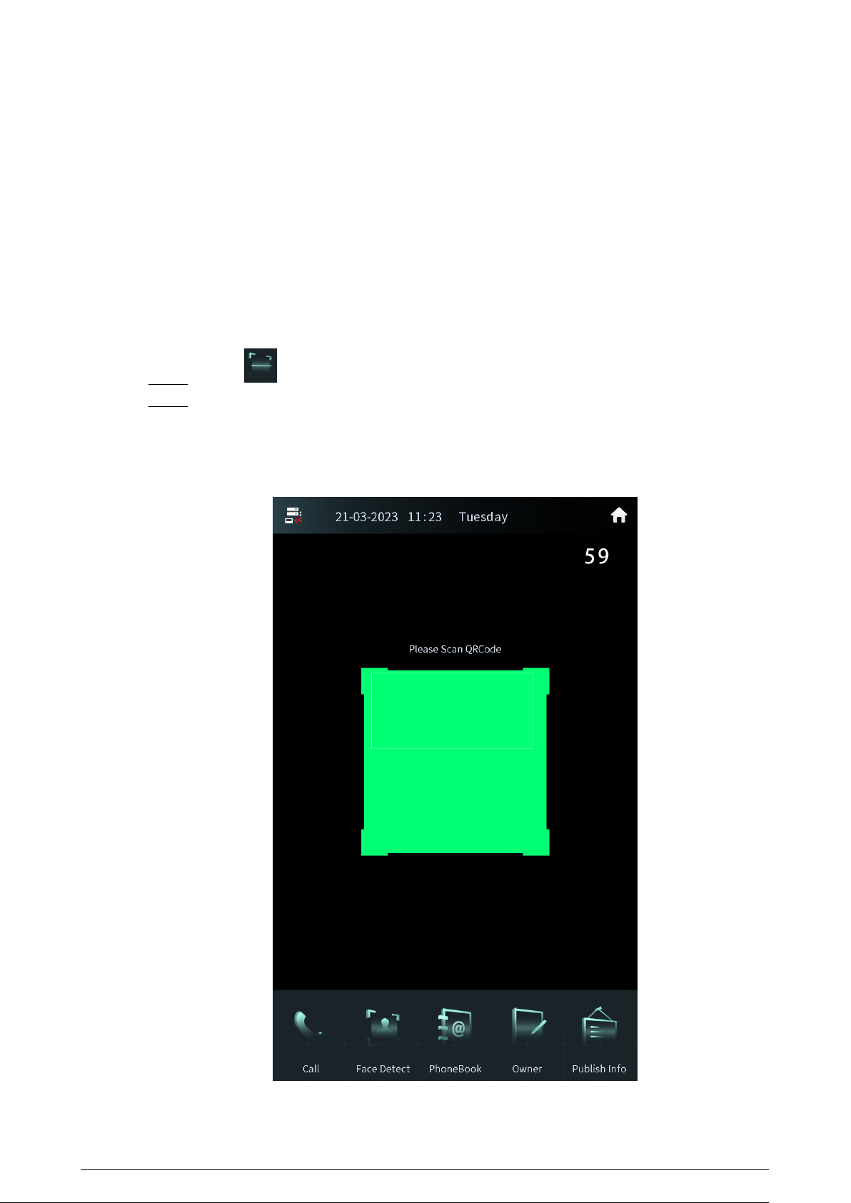
2.2.4.2 Unlocking by Scanning the QR Code
Scan the QR code to open the door. The QR code is sent by the platform. For details, see the user
manual of the corresponding platform.
Procedure
Step 1 Press on the home screen.
Step 2 Show the QR code, and then make sure the QR code is displayed in the viewnder.
The voice prompt and the device prompt Open Successfully means that the door opens
and you can enter. If the device displays Invalid, check the QR code.
Figure 2-44 Scan the QR code
48

2.2.4.3 Unlocking by the Password
Procedure
Step 1 Tap on the home screen.
Step 2 Enter the password to open the door.
●
#+Password+# : The password here is congured through Local Setting > Access
Control > Password Management on the webpage. For example, if the password is
123456, enter "#123456#" to open the door.
●
#+Room number+Password+# : The password here is congured on the VTH. If the
room number has less than 6 digits, you need to enter extra 0 in front. For example, if
the room number is 9901 and the password is 112233, enter "#009901112233#" to
open the door.
You need to change the default password on the VTH rst if you want to use this
method to open the door.
The voice prompt and the device prompt Open Successfully means that the door opens
and you can enter. If the device displays Password Error, check the password.
2.2.4.4 Unlocking by the Card
Brush the authorized card. The voice prompt and the device prompt Open door success means
that the door opens and you can enter. If the device displays Unauthorized, register the card.
2.2.4.5 Unlocking by the Fingerprints
Press the ngerprint. The voice prompt and the device prompt Open door success means that the
door opens and you can enter. If the device displays Unauthorized, register the ngerprint.
2.2.4.6 Unlocking through the VTH
When the VTO calls the VTH or the VTH monitors the VTO, you can press the unlock button on the
VTH for the visitor. The voice prompt and the device prompt Open door success means that the
door opens and you can enter.
2.2.4.7 Unlocking through the VTS
When the VTO calls the VTS or the VTS monitors the VTO, you can press the unlock button on the
VTS for the visitor. The voice prompt and the device prompt Open door success means that the
door opens and you can enter.
2.2.5 Call
49

2.2.5.1 Calling the VTH
Procedure
Step 1 Tap on the home screen.
Step 2 Enter the room number, and then tap Call.
Step 3 Tap on the VTH to receive the call.
2.2.5.2 Calling the Property Management (the VTS)
Procedure
Step 1 Tap on the home screen.
Step 2 Tap .
There is voice prompt Calling, please wait.
Step 3 The VTS receives the call.
2.2.6 Messages
If the VTO calls the VTH and the VTH does not answer the call, the VTO displays prompt. Press 1 to
leave a message. The VTO saves the messages to the SD card of the VTH. The VTH user can view the
messages in Guest Message.
50
3 Webpage Operations
3.1 Logging in to the Webpage
Procedure
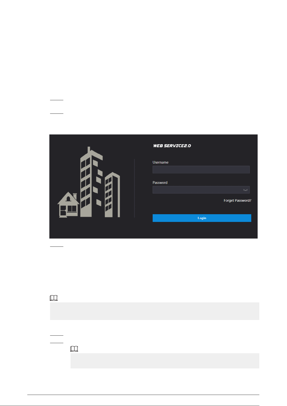
Step 1 Enter the IP address of the VTO in the browser bar to go to the login page, and then press
the Enter key.
Step 2 Enter the username (admin by default) and the password that you congured during the
initialization.
Figure 3-1 Login
Step 3 Click Login.
3.2 Resetting the Password
If you forget the login password of the admin account, scan the QR code to reset it.
Prerequisites
Make sure that you have enabled Reset Password through Local Setting > Security .
If you did not congure the email address during the initialization, the system will report an error.
Please contact the local retailer or the technical support for help.
Procedure
Step 1 Click Forget Password? on the login page, and then click Next.
Step 2 Get the Security Code according to the instructions.
●
You can get up to 2 security codes with the same QR code. If you need more security
codes, you need to refresh the QR code and scan it again.
51
●
The security code will be sent to your email address. You must use it in 24 hours.
Otherwise, the security code will be invalid.
●
The account will be locked for 5 minutes if you enter the wrong security code 5 times
in a row.
Step 3 Enter the security code you received, and then click Next.
Step 4 Enter new password, conrm the new password, and then click OK.
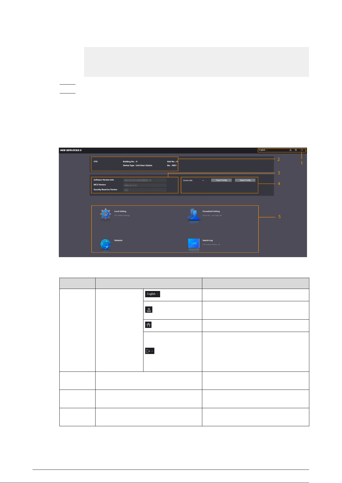
3.3 Home Page Introduction
The system automatically goes to the home page after you log in.
Figure 3-2 Home page
Table 3-1 Description of home page
No.
Parameter Description
1 Navigation Bar
Select a language.
Change the password and the email
address.
Click the icon to go to the home page.
Exit the webpage, restart the device or
restore the device to factory defaults. For
details, see “3.11 Restarting the Device”,
“3.12 Restoring to Factory Defaults” and
“3.13 Logging Out”.
2 Device Information
View the building number, unit number,
device type and the device number.
3 Version Information
View the software version, MCU version
and the security baseline version.
4 Export/Import
Export or import the device information
or the user information.
52
No. Parameter Description
5
Local Setting
Congure the basic information,
parameters of video and audio, access
control, system, security, and Wiegand.
Household Setting
Manage the information of the VTO, VTH,
VTS, IPC and send the announcement.
Network
Congure the network parameters such
as TCP/IP, FTP, UPnP, SIP server and
personnel. Congure the
announcement.
Search Log
Search for call records, alarm records,
unlock records and system logs.
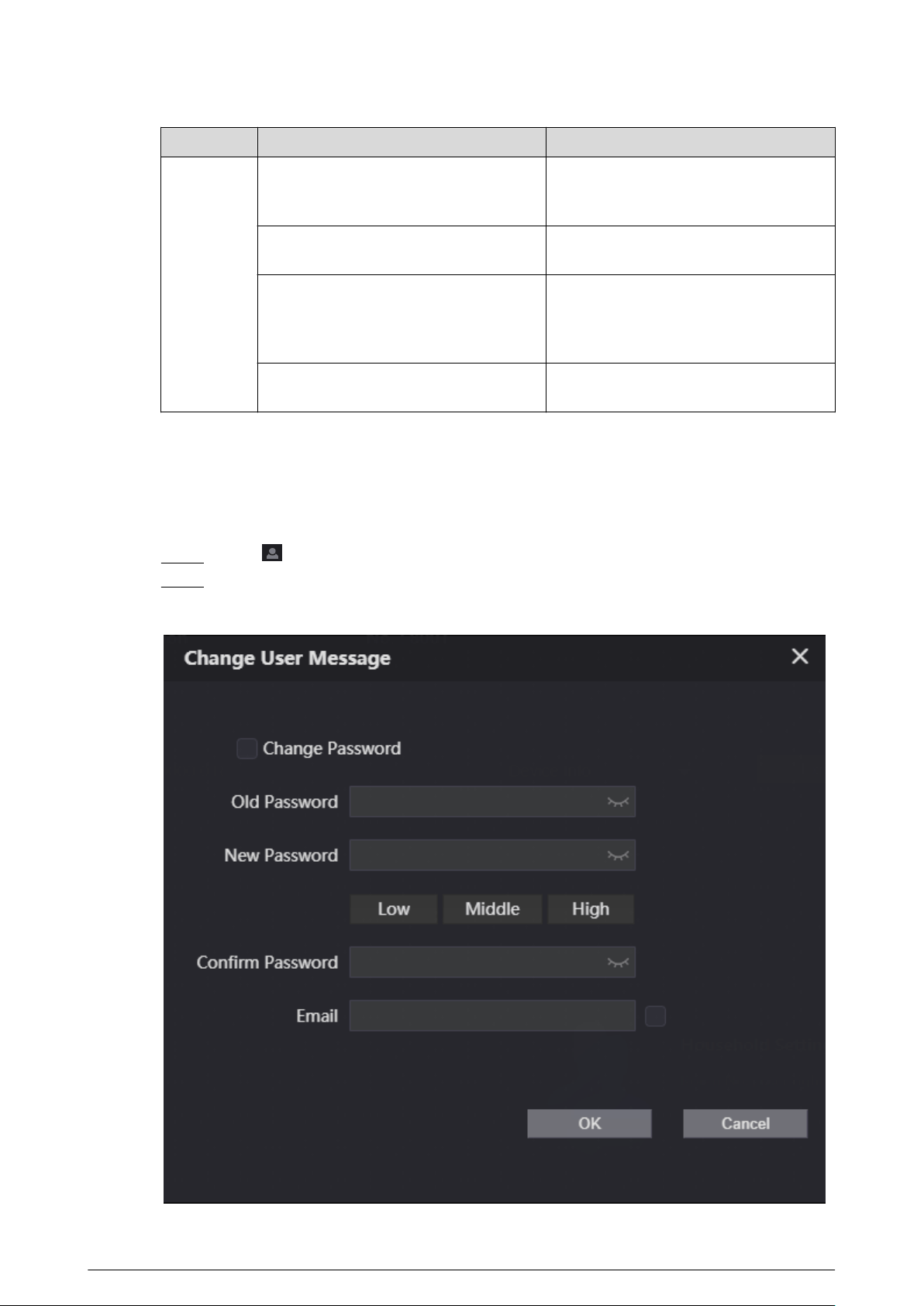
3.4 Changing the User Message
Change the login password and the email address of the user.
Procedure
Step 1 Click on the home page.
Step 2 Select the information.
Figure 3-3 Changing the user message
53
Step 3 Congure the parameters, and then click OK.
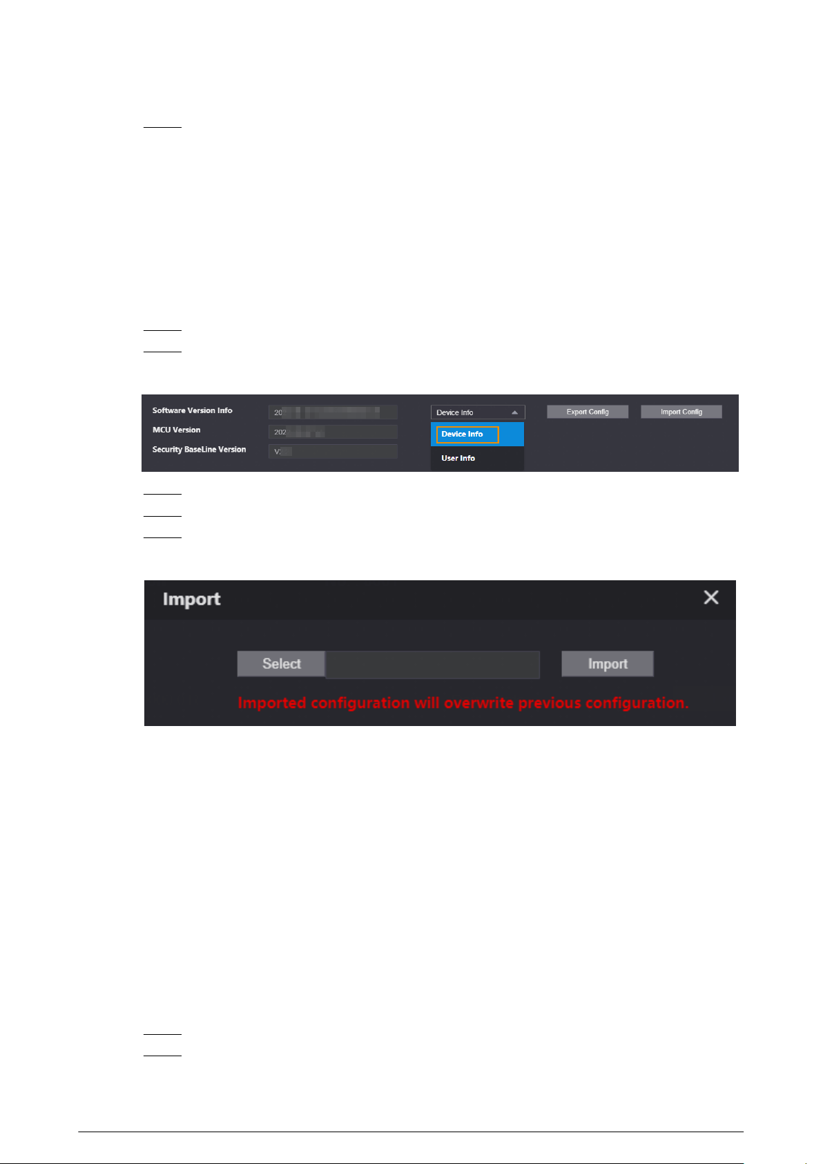
3.5 Import/Export the Device Information
3.5.1 Importing the Device Information
Import the device information to the system.
Procedure
Step 1 Log in to the webpage.
Step 2 Select Device Info.
Figure 3-4 Select the device information
Step 3 Click Import Cong.
Step 4 Click Select to select the device information le.
Step 5 Click Import.
Figure 3-5 Import the device information
3.5.2 Exporting the Device Information
Log in to the webpage, select Device Info , and then click Export Cong to export the information
of the current device to the local computer.
3.6 Import/Export the User Information
3.6.1 Importing the User Information
Import the user information to the system.
Procedure
Step 1 Log in to the webpage.
Step 2 Select User Info.
54
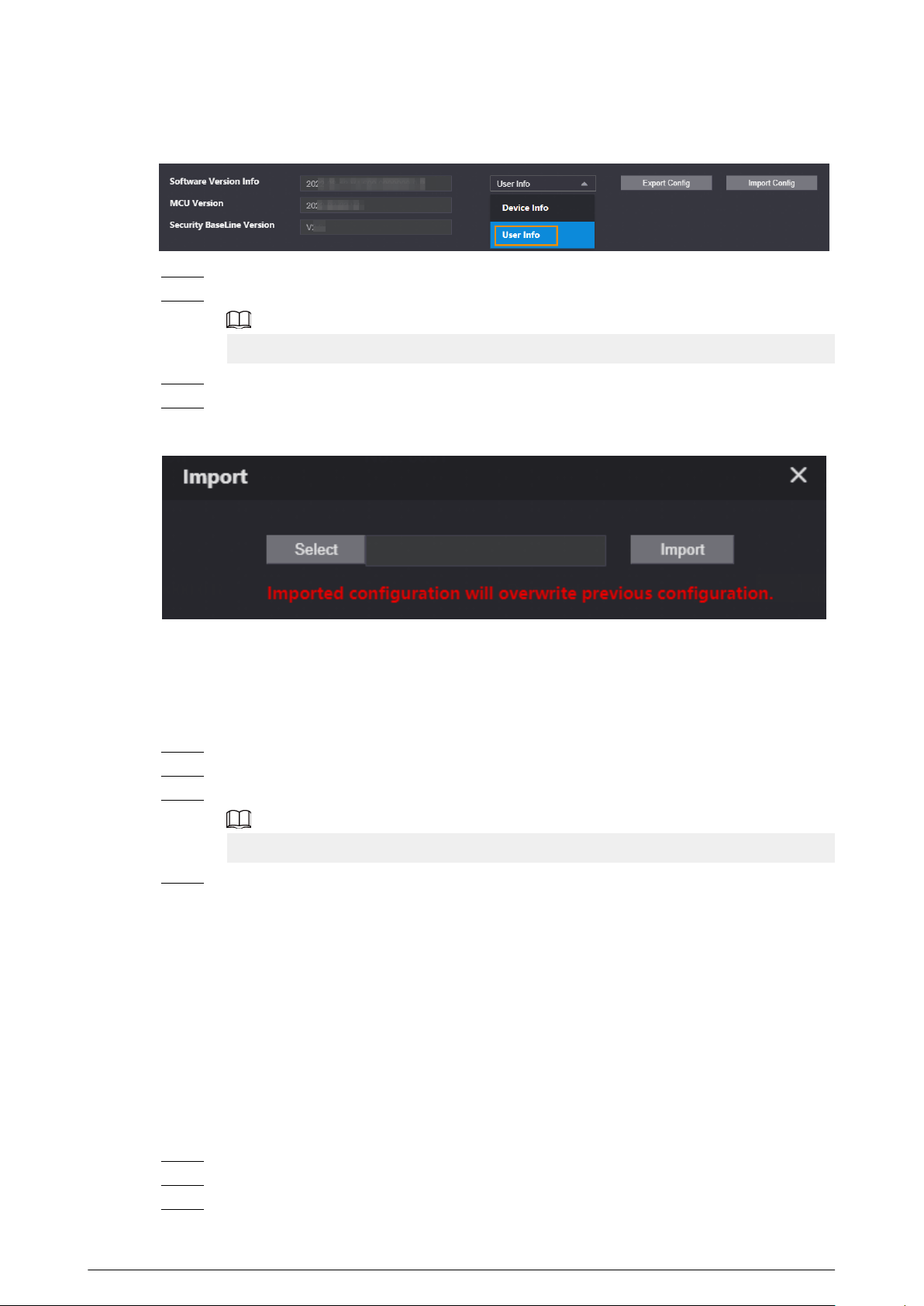
Figure 3-6 Select the user information
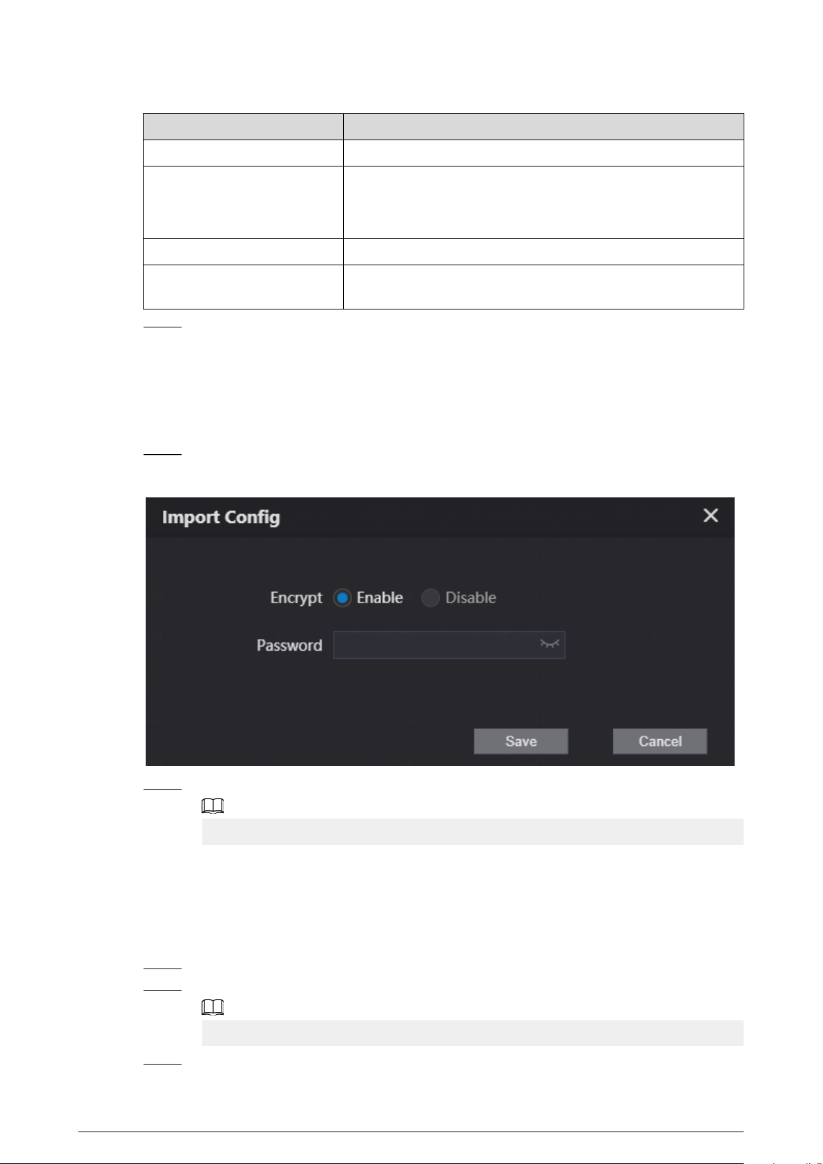
Step 3 Click Import Cong.
Step 4 Enter the password, and then click Save.
The password is congured during export conguration.
Step 5 Click Select to select the user information le.
Step 6 Click Import.
Figure 3-7 Import the user information
3.6.2 Exporting the User Information
Procedure
Step 1 Log in to the webpage.
Step 2 Select User Info , and then click Export Cong.
Step 3 Congure the password.
The password is used to import the user information.
Step 4 Click Save to save the user information le to the local computer.
3.7 Local Setting
3.7.1 Conguring Video and Audio Parameters
3.7.1.1 Conguring Video Parameters
Procedure
Step 1 Log in to the webpage.
Step 2 Select Local Setting > Video & Audio > Video .
Step 3 Congure the video parameters.
55
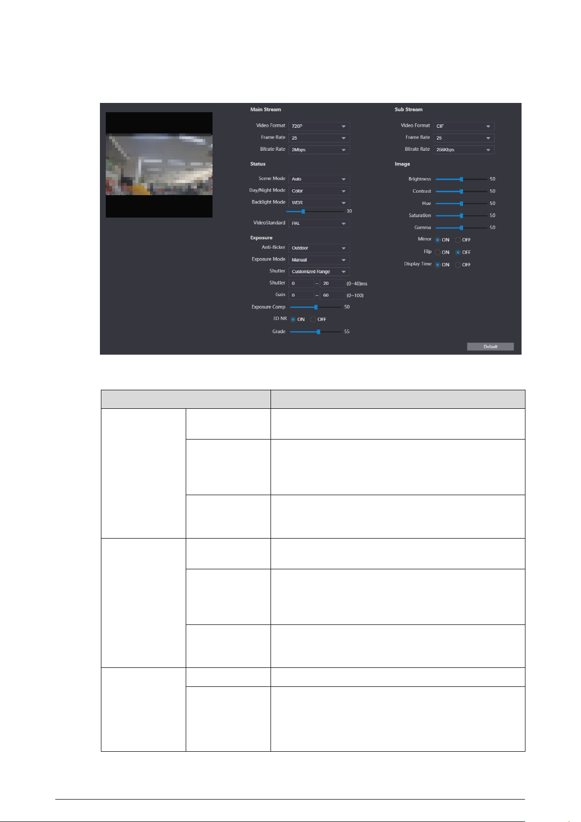
Figure 3-8 Video parameters
Table 3-2 Video parameters description
Parameter
Description
Main Stream
Video Format
Adjust the resolution of the video. You can select from
720P , WVGA , and D1.
Frame Rate
The number of frame in one second of video. If you select
PAL as the video standard, you can set the frame rate up
to 25. If you select NTSC as the video standard, you can
set the frame rate up to 30.
Bitrate Rate
Select from 1024 Kbps , 1.25 Mbps , 1.5 Mbps , 1.75
Mbps , 2 Mbps , and 4 Mbps according to the actual
situation.
Sub Stream
Video Format
Adjust the resolution of the video. You can select from
WVGA , D1 , QVGA , CIF , and 1080P.
Frame Rate
The number of frame in one second of video. If you select
PAL as the video standard, you can set the frame rate up
to 25. If you select NTSC as the video standard, you can
set the frame rate up to 30.
Bitrate Rate
Select from 256 Kbps , 320 Kbps , 384 Kbps , 448 Kbps ,
512 Kbps , 640 Kbps and 768 Kbps according to the
actual situation.
Status
Scene Mode Select from Auto , Sunny , Night and Disabled
Day/Night Mode
●
Auto : The system switches between color and black-
and-white according to actual conditions.
●
Color : The system displays the image in color.
●
B/W : The system displays black-white image.
56

Parameter Description
Backlight Mode
●
Disabled : There will be no backlight.
●
BLC : The system gets a clearer image of the dark areas
on the target when shooting against light.
●
WDR : The system dims bright areas and compensates
for dark areas to ensure the clarity of all areas.
●
HLC : The system dims strong lights, and reduce the
size of Halo zone to lower the brightness of the whole
image.
Video Standard Select from PAL and NTSC.
Exposure
Anti-icker
●
50Hz : The system adjusts the exposure according to
ambient light automatically to ensure that stripes do
not appear.
●
60Hz : The system adjusts the exposure according to
ambient light automatically to ensure that stripes do
not appear.
●
Outdoor : If you select Outdoor, the exposure mode
can be set to Gain Priority, Shutter Priority and Iris
Priority. Dierent devices support dierent exposure
modes.
Exposure Mode
●
Auto : Exposure is automatically adjusted according to
scene brightness if the overall brightness of images is
in the normal exposure range.
●
Manual : You can adjust the Gain and Shutter value
manually.
Shutter
Set the eective exposure time. The smaller the value, the
shorter the exposure time.
Shutter Range
If you select Manual as the exposure mode, and select
Customized Range as the shutter, you can set the
shutter range in ms unit.
Gain Range
If you select Manual as the exposure mode, you can set
the gain range to automatically increase the gain of the
device when the illumination is low, thus obtaining a clear
image.
Exposure Comp
You can set the exposure compensation value. The value
ranges from 0 to 100. The higher the value is, the brighter
the image will be.
3D NR
Reduce the noise of multiple-frame (at least two frames)
images by using inter-frame information between two
adjacent frames in a video. The higher the level is, the
lower the noise will be, and the larger the trailing smear
will be.
Grade
Noise reduction grade. The value ranges from 0 to 100.
The larger the value is, the less the noise will be.
Image
Brightness
Change the overall brightness of the image. The higher
the value, the brighter the image.
57
Parameter Description
Contrast
Change the contrast of the image. The higher the value,
the greater the contrast between bright and dark areas. If
the value is too big, the dark area will be too dark and the
bright area will be more vulnerable to overexposure.
Hue
Makes the color deeper or lighter. The default value is
made by the light sensor, and it is recommended.
Saturation
Set the intensity of colors. The higher the value, the
deeper the color. Saturation value does not change image
brightness.
Gamma
Change the image brightness and contrast in a non-linear
way. The higher the value, the brighter the image.
Mirror If you select ON, the image ips left and right.
Flip If you select ON, the image ips up and down.
Display Time
If you select ON, the current time displays on the video
image.
3.7.1.2 Conguring Audio Parameters
Procedure
Step 1 Log in to the webpage.
Step 2 Select Local Setting > Video & Audio > Audio .
Step 3 Congure the audio parameters.
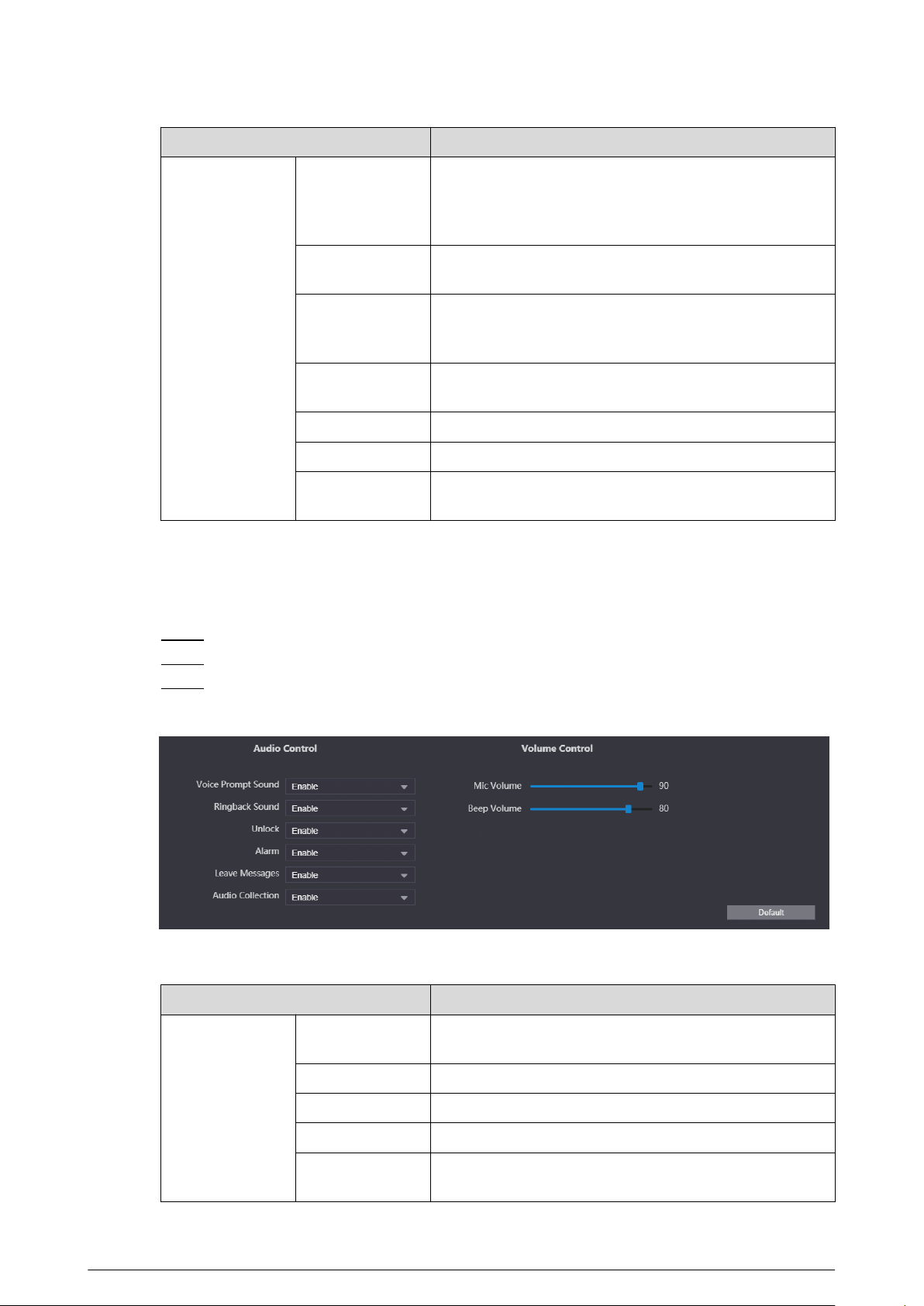
Figure 3-9 Audio parameters
Table 3-3 Audio parameters description
Parameter
Description
Audio Control
Voice Prompt
Sound
If enabled, there is prompt sound when you call.
Ringback Sound If enabled, there is ringback sound when you call.
Unlock If enabled, there is prompt sound.
Alarm If enabled, there is alarm sound.
Leave Messages
If enabled, when no one answers the call from the visitor,
the system plays prompt sound for messages.
58
Parameter Description
Audio Collection If enabled, the audio will be saved.
Volume Control
Mic Volume
Adjust the microphone volume of the VTO. The higher the
value is, the higher the volume will be.
Beep Volume
Adjust the beep volume of the VTO. The higher the value
is, the higher the volume will be.
3.7.2 Conguring Access Control Parameters
3.7.2.1 Conguring Local Lock
The local lock refers to the lock that is connected to the function port of the VTO. You can congure
the responding interval, unlock period, password and other parameters. For details about the
function port connection, see “1.4 Rear Panel”.
Procedure
Step 1 Log in to the webpage.
Step 2 Select Local Setting > Access Control > Local .
Step 3 Congure the parameters of the local lock.
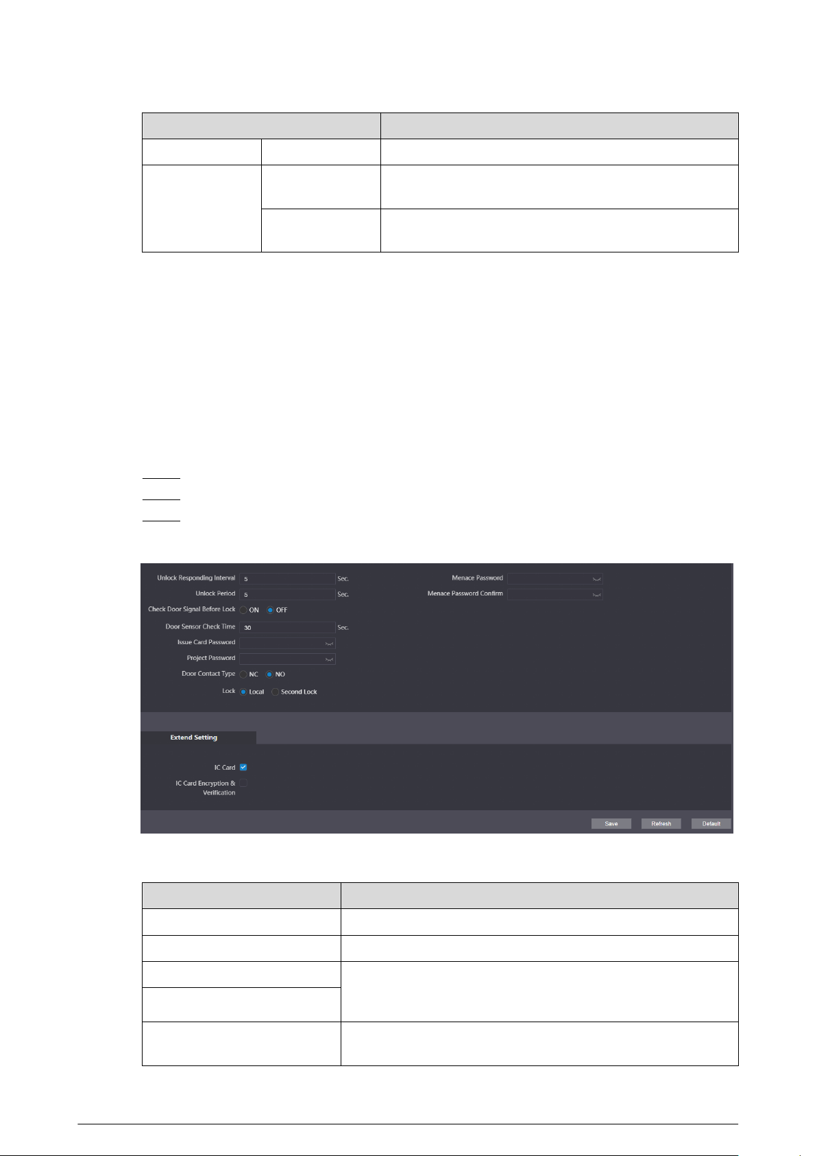
Figure 3-10 Local lock
Table 3-4 Parameter description of the local lock
Parameter
Description
Unlock Responding Interval The interval to unlock again after the previous unlock.
Unlock Period The duration for which the lock stays open after unlock.
Check Door Signal Before Lock If you select ON, congure the check time. When the unlock time
exceeds the check time that you congured, the door sensor
alarm is triggered, and the alarm will be sent to the VTS.
Door Sensor Check Time
Issue Card Password
Used to issue new cards. For details, see “2.2.2.3.4 Issuing Cards”
or “2.1.2.3.3 Issuing Cards”.
59
Parameter Description
Project Password Used to go to the engineer setting screen on the VTO.
Door Contact Type
●
NC: Normally closed.
●
NO: Normally open.
Lock
Select from Local and Second Lock to congure the authority
for opening the local lock and the second lock.
Menace Password Congure the menace password. If you enter the password
when you are forced, the alarm will be sent to the management
center.
Menace Password Conrm
IC Card When enabled, IC card can be used to open the door.
IC Card Encryption &
Verication
When enabled, the IC card is encrypted. Swipe the right card
with successful encryption detection to open the door.
Step 4 Click Save.
3.7.2.2 RS485
The lock can be connected through RS-485 port.
Procedure
Step 1 Log in to the webpage.
Step 2 Select Local Setting > Access Control > RS485 .
Step 3 Select Lock as the interface type.
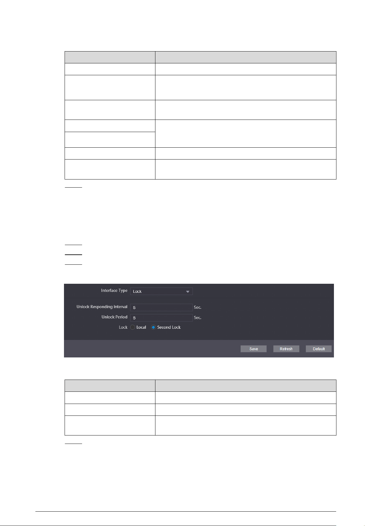
Figure 3-11 RS-485 lock
Table 3-5 Parameter description of RS-485 lock
Parameter
Description
Unlock Responding Interval The time interval to unlock again after the previous unlock.
Unlock Period The time amount for which the lock stays open after unlock.
Lock
Select from Local and Second Lock to congure the authority
for opening the local lock and the second lock.
Step 4 Click Save.
60
3.7.2.3 Conguring the Password
Congure the door opening password.
Procedure
Step 1 Log in to the webpage.
Step 2 Select Local Setting > Access Control > Password Management .
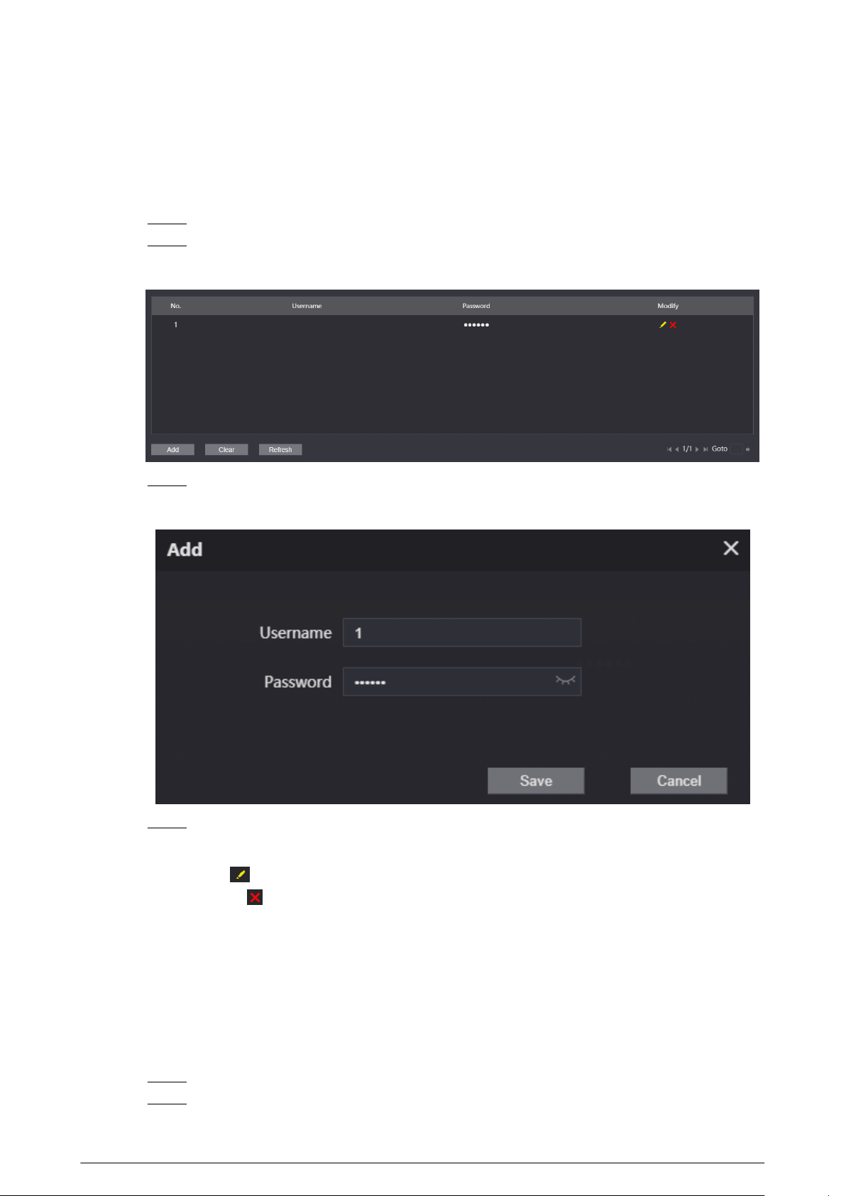
Figure 3-12 Password management
Step 3 Click Add.
Figure 3-13 Add the password
Step 4 Congure the username and the password, and then click Save.
Related Operations
●
Edit: Click
to edit the password.
●
Delete: Click to delete the password.
●
Clear: Click Clear to delete all the passwords.
●
Refresh: Click Refresh to refresh the page.
3.7.3 Conguring System Parameters
Congure the date format, time format, system time, NTP server and other parameters.
Procedure
Step 1 Log in to the webpage.
Step 2 Select Local Setting > System .
61
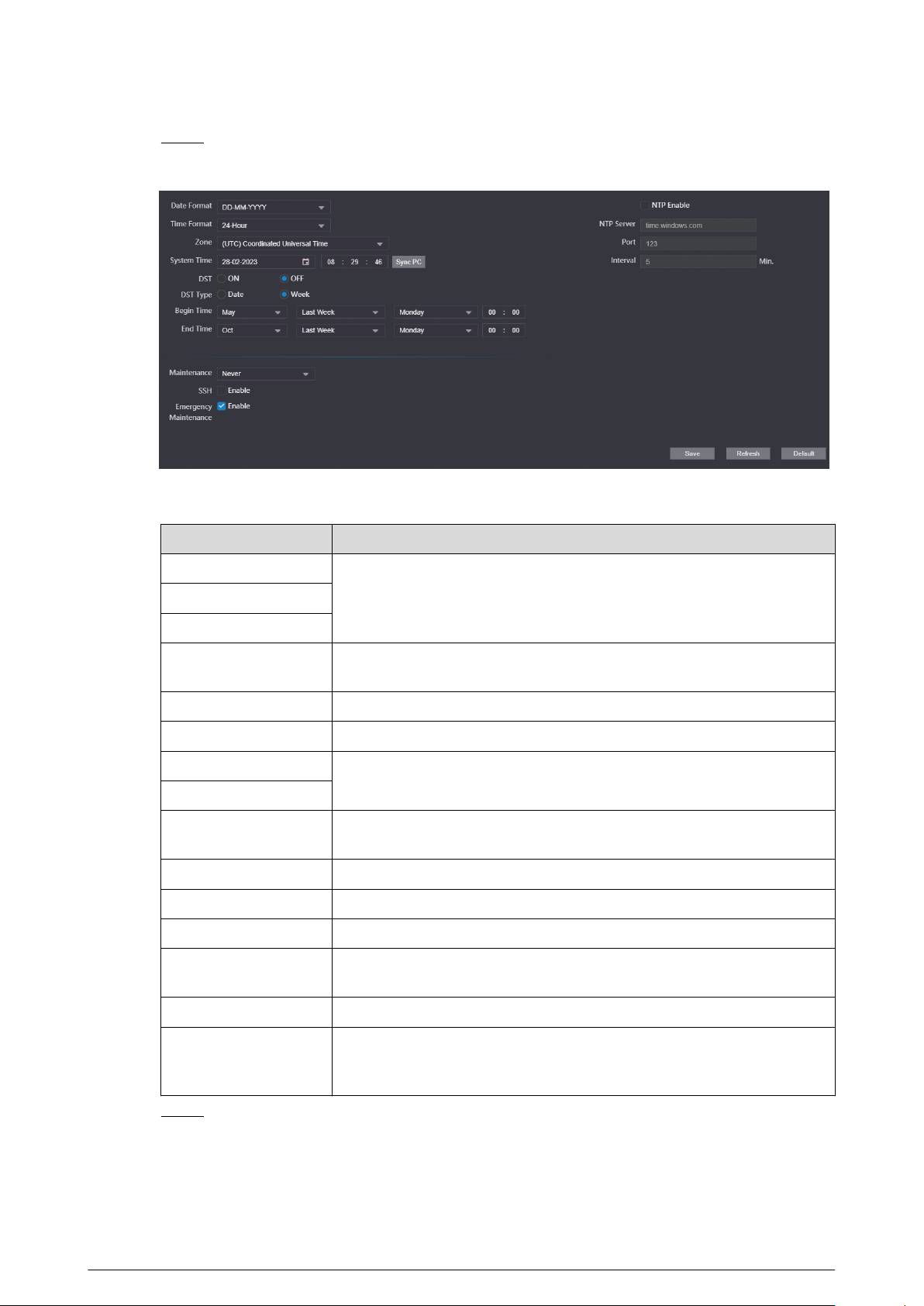
Step 3 Congure the system parameters.
Figure 3-14 System parameters
Table 3-6 System parameters description
Parameter Description
Date Format
Congure the date format, time format and the zone.Time Format
Zone
System Time
Manually congure the system time. You can also click Sync PC to
synchronize the time of the VTO with the local computer.
DST Select from ON and OFF.
DST Type Select from Date and Week.
Begin Time
Congure the begin time and end time for DST.
End Time
NTP Enable
If selected, the system will synchronize its time with the NTP server you
congure.
NTP Server Congure the address of the NTP server.
Port The port number of the NTP server. The number is 123 by default.
Interval The interval that the VTO synchronize the time with the NTP server.
Maintenance
Select the maintenance time. The device will automatically restart at the
time to maintain the operating speed.
SSH If enabled, you can log in to the VTO through SSH.
Emergency
Maintenance
When this function is enabled, if the device fails to restart 5 times in a
row, it will automatically turn on a service port used by technical support
to perform upgrades and recovery.
Step 4 Click Save.
62
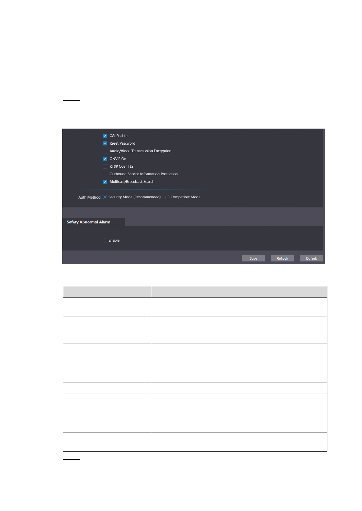
3.7.4 Conguring Security Management
Procedure
Step 1 Log in to the webpage.
Step 2 Select Local Setting > Security .
Step 3 Congure the security parameters.
Figure 3-15 Security management
Table 3-7 Description of security parameters
Parameter
Description
CGI Enable
Enabled by default. The VTO can be connected with other video
products through CGI (Common Gateway Interface) protocol.
Reset Password
Enabled by default. Enable the function, and then congure the
email address. After conguration, you can click Forget
Password? on the login page to reset the password.
Audio/Video Transmission
Encryption
Transfer the audio and video data in encryption.
ONVIF On
Enabled by default. The VTO can be connected with other video
products through ONVIF protocol.
RTSP Over TLS Transfer the RTSP data in encryption.
Outbound Service Information
Protection
If enabled, the device password cannot be got through the third
protocol tool.
Multicast/Broadcast Search
If enabled, you can search for the device through multicast/
broadcast protocol.
Auth Method
Congure the authentication method. You can select from
Security Mode (Recommended) and Compatible Mode.
Step 4 Click Save.
63
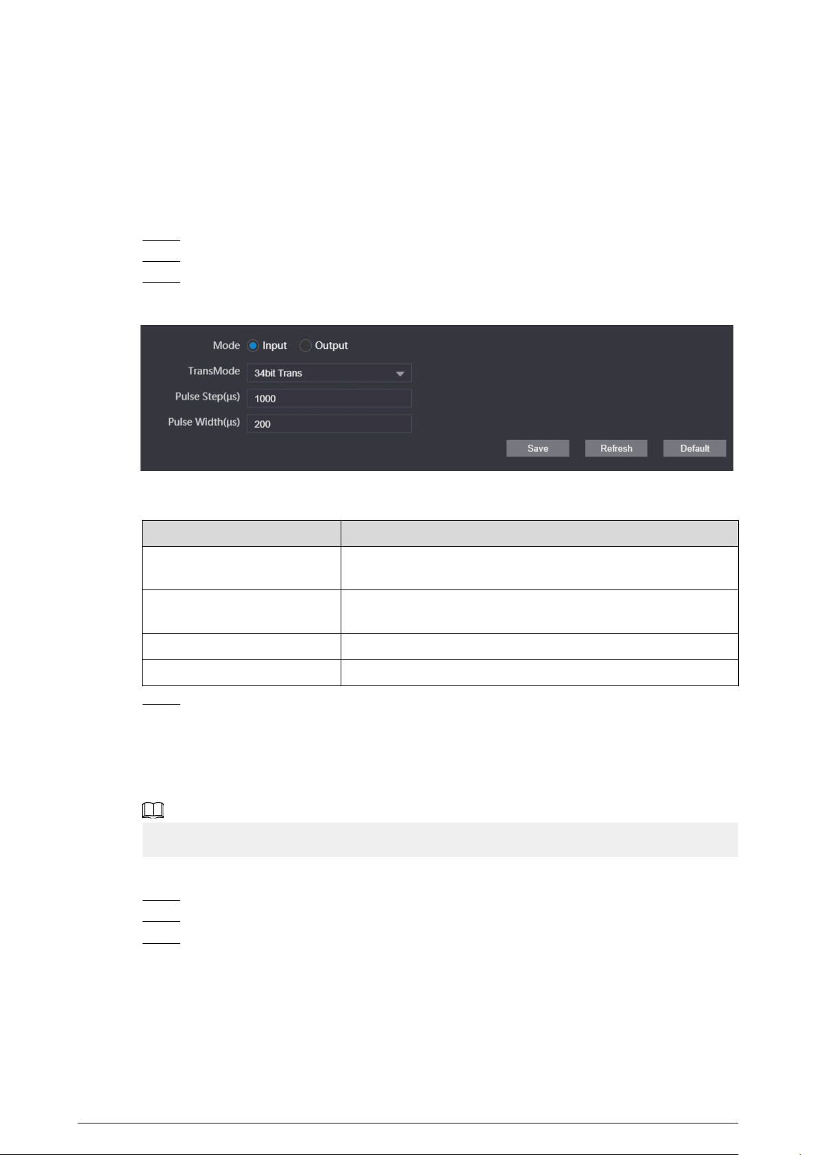
3.7.5 Conguring Wiegand Parameters
Supports access Wiegand devices such as Wiegand reader and access controller. Congure the
mode and the transmission mode according to your actual devices.
Procedure
Step 1 Log in to the webpage.
Step 2 Select Local Setting > Wiegand .
Step 3 Congure the Wiegand parameters.
Figure 3-16 Wiegand parameters
Table 3-8 Description of Wiegand parameters
Parameter
Description
Mode
Select from Input and Output according to the devices you
connect.
TransMode
Select from 34 bit Trans , 66 bit Trans and 26 bit Trans. The
higher the value is, the faster the transmission will be.
Pulse Step The Wiegand signal frequency. It is 1,000 by default.
Pulse Width The max value of Wiegand signal. It is 200 by default.
Step 4 Click Save.
3.7.6 Conguring Face Detection Parameters
Congure the threshold, detection angle and other parameters.
The face detection is available on select models.
Procedure
Step 1 Log in to the webpage.
Step 2 Select Local Setting Face Detection
Step 3 Congure the face detection parameters.
64
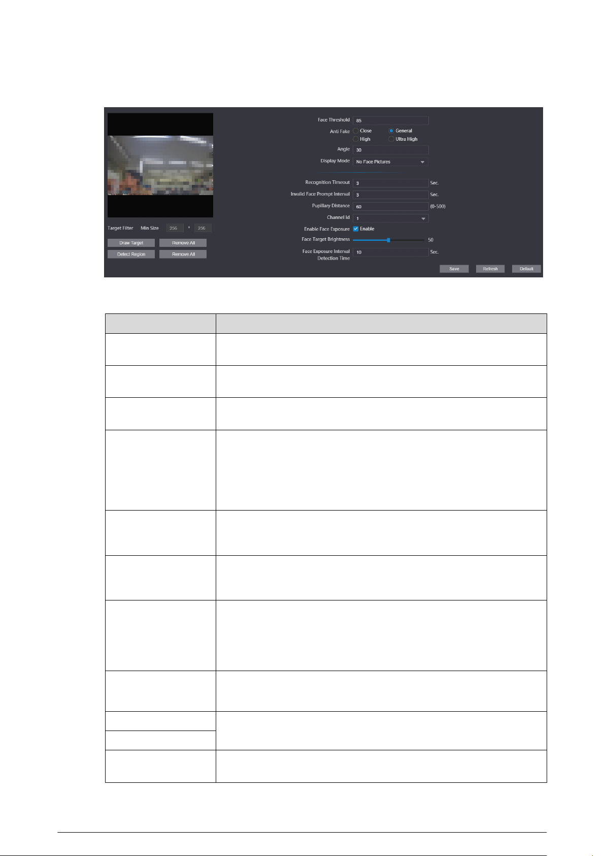
Figure 3-17 Face detection parameters
Table 3-9 Parameter description of face detection
Parameter Description
Face Threshold
Adjust the accuracy for face detection. Higher threshold means higher
accuracy.
Anti Fake
Select the level to avoid using the photo or the video of the authorized
people to open the door.
Angle
Set the maximum face pose angle for face detection. Larger value means
larger face angle range.
Display Mode
●
No Face Pictures: Displays character prompt.
●
Only Face Pictures: Displays the face picture that saved in the face
database.
●
Snapshots and Face Pictures: Displays the snapshot and the face
picture that saved in the face database.
Recognition Timeout
If a person with access permission has their face successfully recognized,
the VTO will prompt success recognition. Congure the prompt interval
time.
Invalid Face Prompt
Interval
If a person without access permission attempts to unlock the door for
several times in the dened interval, the VTO will prompt invalid.
Congure the prompt interval time.
Pupillary Distance
Face images require desired pixels between the eyes (called pupillary
distance) for successful recognition. The pixel changes according to the
face size and the size and the distance between faces and the lens. If an
adult is 1.5 meters away from the lens, the pupillary distance can be 50
px–70 px.
Channel Id
●
1 : White light.
●
2 : IR light.
Enable Face Exposure
If enabled, the VTO will increase the brightness according to the
congured value only for the face target in outdoor places.
Face Target Brightness
Face Exposure Interval
Detection Time
After the exposure for the face target, if the device recognizes the face
again within the congured time, there is no exposure.
65
Step 4 Click Save.
Related Operations
●
Draw Target
Click Draw Target to congure the minimum detection box.
Click Remove All to clear the congured detection box.
●
Detect Region
Click Detect Region to congure the detection region. Click the points to adjust the detect
region to a polygon.
Click Remove All to clear the congured detection region.
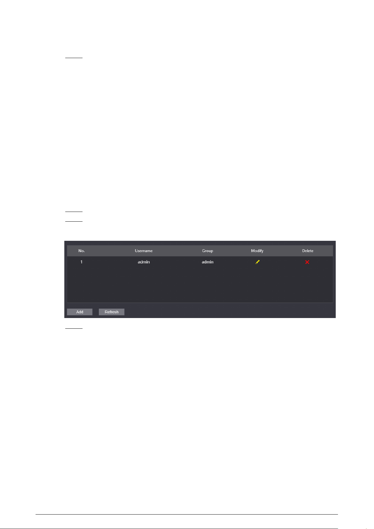
3.7.7 Adding ONVIF Users
ONVIF users are used for ONFVIF protocol. The ONVIF user information will be veried before the
door opens.
Procedure
Step 1 Log in to the webpage.
Step 2 Select Local Setting > Onvif User .
Figure 3-18 ONVIF user
Step 3 Click Add, and then enter the username, password and conrm password.
66
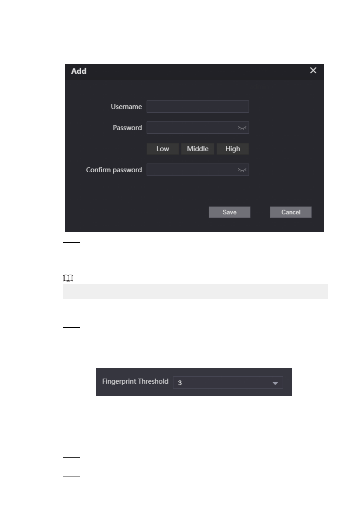
Figure 3-19 Add the user
Step 4 Click Save.
3.7.8 Conguring Fingerprint Recognition Parameters
Fingerprint recognition is available on select models.
Procedure
Step 1 Log in to the webpage.
Step 2 Select Local Setting > Fingerprint Recognition .
Step 3 Congure the ngerprint threshold.
The higher the value is, the more accurate the match result is.
Figure 3-20 Congure the ngerprint parameter
Step 4 Click Save.
3.7.9 Uploading Audio Files
Procedure
Step 1 Log in to the webpage.
Step 2 Select Local Setting > Upload File .
Step 3 Select the audio type.
67

Step 4 Click Browse, and then select the audio le from the local computer.
Step 5 Click Upload.
Figure 3-21 Upload the le
3.7.10 Viewing the Legal Information
Log in to the webpage. Select Local Setting > Legal Info to view Software License Agreement ,
Privacy Policy and Open Source Software Notice.
3.8 Household Setting
3.8.1 Adding the VTO
For details, see Video Door Phone_Quick Start Guide.
3.8.2 Adding the VTH
For details, see Video Door Phone_Quick Start Guide.
3.8.3 Adding the VTS
If the current VTO works as the SIP server, you need to add the VTS to enable the video intercom
between the VTO and the VTS.
Procedure
Step 1 Log in to the webpage.
Step 2 Select Household Setting > VTS Settings .
Step 3 Click Add, and then congure the parameters.
68
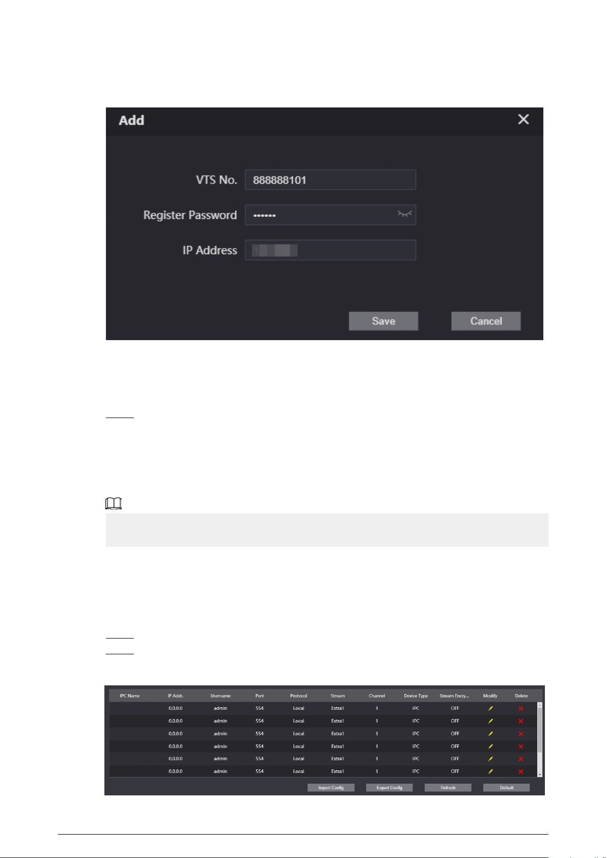
Figure 3-22 Add the VTS
●
The VTS number ranges from 888888101–888888999.
●
Leave the register password as a default. If you want to register the password, make
sure that it is the same with the register password of the VTS.
●
IP address is the address of the VTS.
Step 4 Click Save.
3.8.4 Adding the IPC
If the current VTO works as the SIP server, you can add the IPC devices on the webpage of the VTO.
The VTHs with the same online SIP server gets the IPC information.
●
Supports adding the device with up to 32 channels.
●
Supports directly adding IPC devices. You can get the IPC channel by adding NVR/XVR/HCVR.
3.8.4.1 Adding the IPC One by One
Add the information of the video monitoring device one by one.
Procedure
Step 1 Log in to the webpage.
Step 2 Select Household Setting > IPC Setting .
Figure 3-23 IPC setting
69
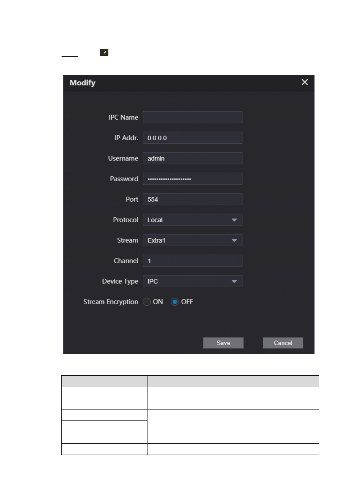
Step 3 Click to congure the parameters.
Figure 3-24 Congure the parameters
Table 3-10 Parameters description of the video monitoring device
Parameter
Description
IPC Name Enter the name of the IPC/VNR/XVR/HCVR device.
IP Addr. Enter the IP address of the IPC/VNR/XVR/HCVR device.
Username
Enter the username and the password that used to log in to the
webpage of the IPC/VNR/XVR/HCVR device.
Password
Port The value is 554 by default.
Protocol Select from Local and ONVIF according to the device you add.
70
Parameter Description
Stream The value is Extra1 by default.
Channel
●
If you add the IPC, it is 1 by default.
●
If you add the NVR/XVR/HCVR, it is the channel of IPC that
was congured on the VNR/XVR/HCVR device.
Device Type Select the type according to the actual devices.
Stream Encryption
Keep consistent with the encryption status of the terminal
device.
Step 4 Click
Save.
3.8.4.2 Importing the IPC Information in Batches
Import the IPC information to the system.
Procedure
Step 1 Click Import Cong.
Figure 3-25 Import conguration
Step 2 Enter the password, and then click Save.
The password is congured during export conguration.
3.8.4.3 Exporting the IPC Information in Batches
Export the IPC information and save the information to the local computer.
Procedure
Step 1 Click Export Cong.
Step 2 Congure the password, and then click Save.
The password is used to import the user information.
Step 3 Click Save to save the IPC conguration le to the local computer.
71
3.8.5 Viewing the Online Devices
If the current VTO works as the SIP server, the administrator can view the information of the online
devices that have connected to the current SIP server.
Figure 3-26 Online devices
3.8.6 Announcement
If the current VTO works as the SIP server, you can send announcements to the VTH through the
webpage. You can also view the history records.
3.8.6.1 Sending the Announcement
Procedure
Step 1 Log in to the webpage.
Step 2 Select Household Setting > Announcement > Send Info .
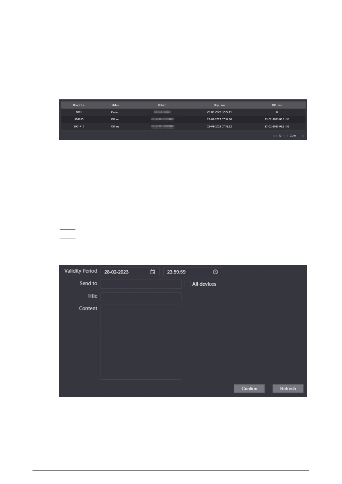
Step 3 Congure the parameters.
Figure 3-27 Send the announcement
72
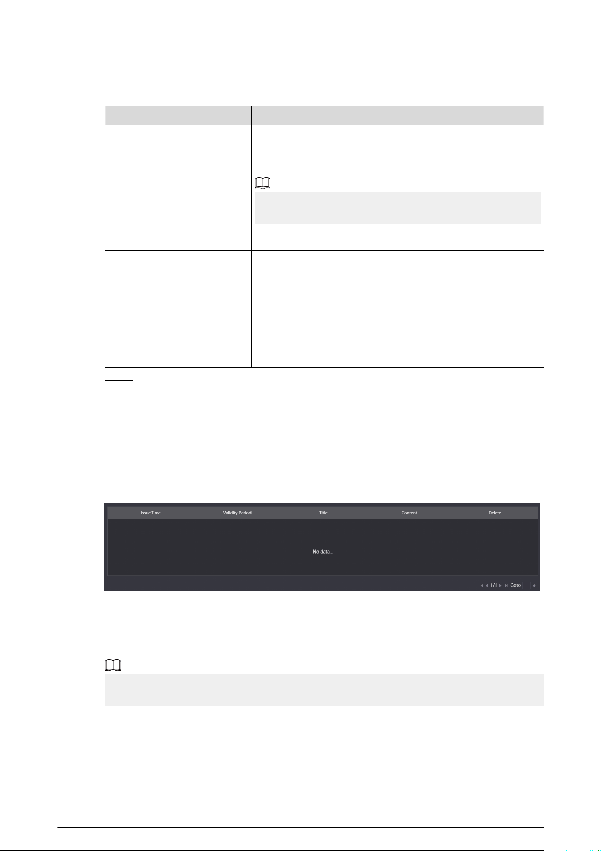
Table 3-11 Description of announcement parameters
Parameter Description
Validity Period
Congure the validity period. You need to send the
announcement within the validity period to enable the VTH
receive the announcement.
The history records will display all the announcements that sent
by the VTO.
Send to Congure the receiver of the announcement.
All Devices
●
Enter the room number of the receiver to solely send the
announcement.
●
Select All devices checkbox to send the announcement to
all devices.
Title The title of the announcement.
Content
The content of the announcement. You can enter up to 256
characters.
Step 4 Click Conrm.
The system sends the announcement to the VTH.
3.8.6.2 Viewing the History Announcement
Log in to the webpage. Select Household Setting > Announcement > History Info . You can
view or delete the history records.
Figure 3-28 View the history records
3.8.7 Personnel Management
Manage and view the information of the people, cards and ngerprints.
The card and ngerprint information that registered on the VTO will be uploaded to the personnel
management in real time.
Log in to the webpage. Select Household Setting > Personnel Management .
73
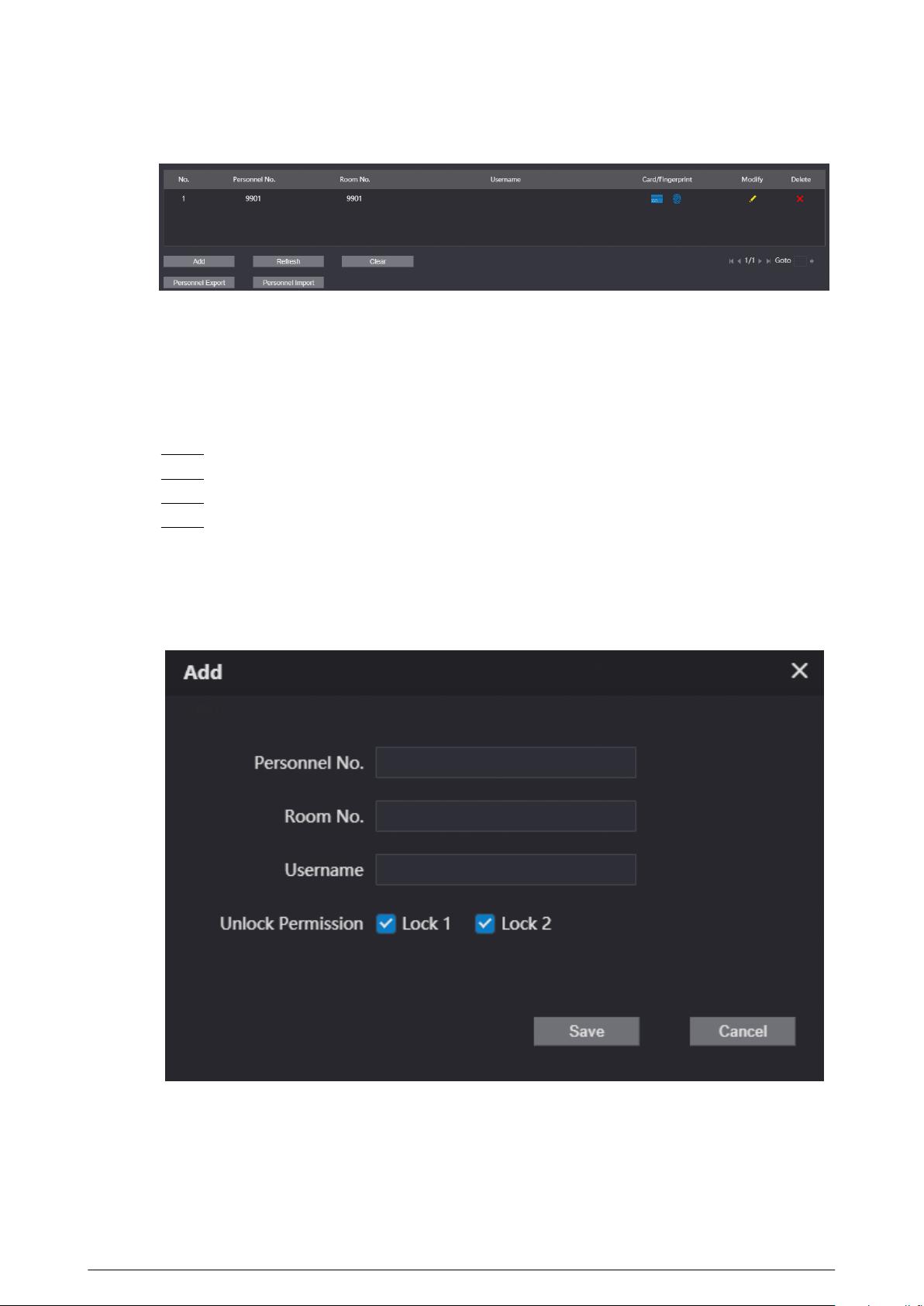
Figure 3-29 Personnel management
3.8.7.1 Adding People
Add the people information to manage the information on the webpage. Supports adding
individually and adding in batches.
Procedure
Step 1 Log in to the webpage.
Step 2 Select Household Setting > Personnel Management .
Step 3 Click Add.
Step 4 Enter the personnel number, room number and the username, and then click Save.
●
Personnel No. : You can customize the number.
●
Room No. : Enter the corresponding room number of the VTH.
●
Username : Enter the name of the people.
Figure 3-30 Congure the parameters
3.8.7.2 Card Management
The VTO uploads the card information to the webpage after you registered on the device. You can
view the card information, report the loss and delete the card.
74
3.8.7.2.1 Reporting the Loss
If you lose the card, we recommend you report the loss quickly.
Click to enter the card information page. Click , and the icon turns . The access
authentication of this card becomes invalid.
If you need to restore the access authentication, click again.
3.8.7.2.2 Deleting the Card
Click to delete the card individually. You can click Clear to delete all the cards.
3.8.7.3 Clearing the Fingerprints
The VTO uploads the ngerprint information to the webpage after you registered on the device.
You can view the ngerprint information and delete the ngerprints.
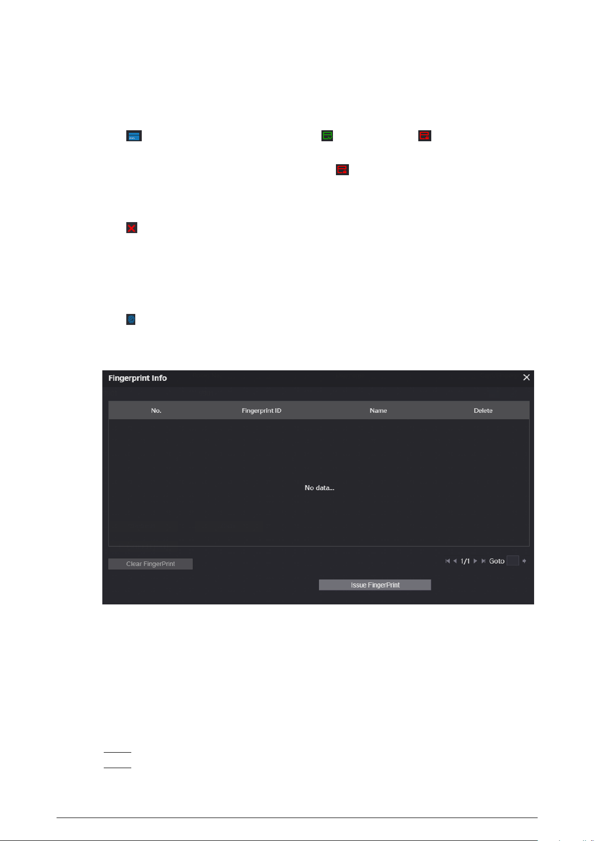
Click to view the ngerprint information of the people. Click Clear Fingerprint to clear all the
ngerprints of the selected people.
Figure 3-31 Fingerprint information
3.9 Network
3.9.1 Conguring the Basic Parameters
Congure the IP address and other network parameters of the VTO and the web ports.
Procedure
Step 1 Log in to the webpage.
Step 2 Select Network > Basic .
75
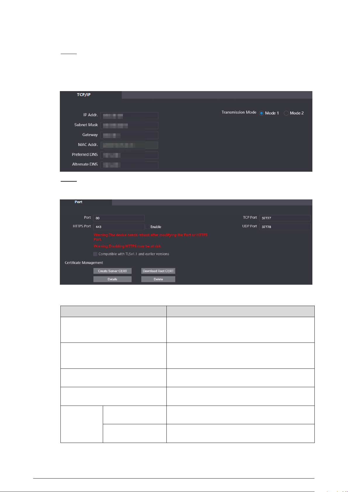
Step 3 Congure the parameters of TCP/IP.
Enter the IP address, subnet mask, gateway of the VTO and the IP address of the preferred
DNS server and the alternate DNS server.
Figure 3-32 Congure the TCP/IP parameters
Step 4 Congure the web pot.
Figure 3-33 Web port
Table 3-12 Parameters description of web port
Parameter
Description
Port
Web port is 80 by default. If you change the port
number, add the changed port number after the IP
address when you log in via a web browser.
HTTPS Port
Enter the port number, and then select Enable to
enable HTTPS function. You can enter https://VTO
IP:HTTPS port number to go to the webpage of the VTO.
TCP Port
TCP protocol provides the port of the service. Default
value is 37777.
UDP Port
Default value of the user datagram protocol port is
37778.
Certicate
Management
Create Server CERT
If you use this function for the rst time or change the
device IP, click Create Server CERT.
Download Root CERT
If you use HTTPS for the rst time after you change the
computer, click Download Root CERT.
76

Parameter Description
Details
Click to view the region, province, location and other
detailed information.
Delete Delete the server certicate.
Step 5 Click Save.
3.9.1.1 Creating the Server Certicate
Install the server certicate that was manually created to enable the normal login and improve your
website security.
●
If you use HTTPS for the rst time or the IP address of the device is changed, create a server
certicate, and then install a root certicate.
●
If you change a computer to log in to the webpage, you need to download and install the root
certicate again on the new computer or copy it to the new computer.
Procedure
Step 1 On the Basic page, click Create Serve CERT.
Step 2 Enter the region, province and other information.
77
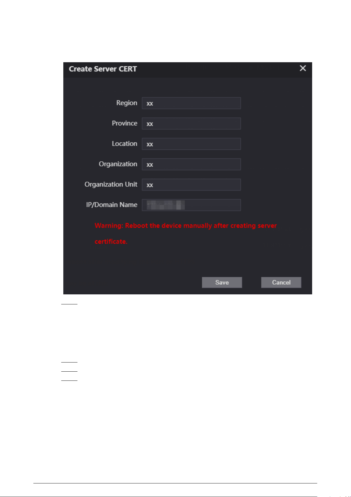
Figure 3-34 Create the server certicate
Step 3 Click Save.
The device will restart.
3.9.1.2 Downloading and Installing the Root Certicate
Procedure
Step 1 On the Basic page, click Download ROOT CERT.
Step 2 Double-click the le that you have downloaded.
Step 3 Click Install Certicate.
78
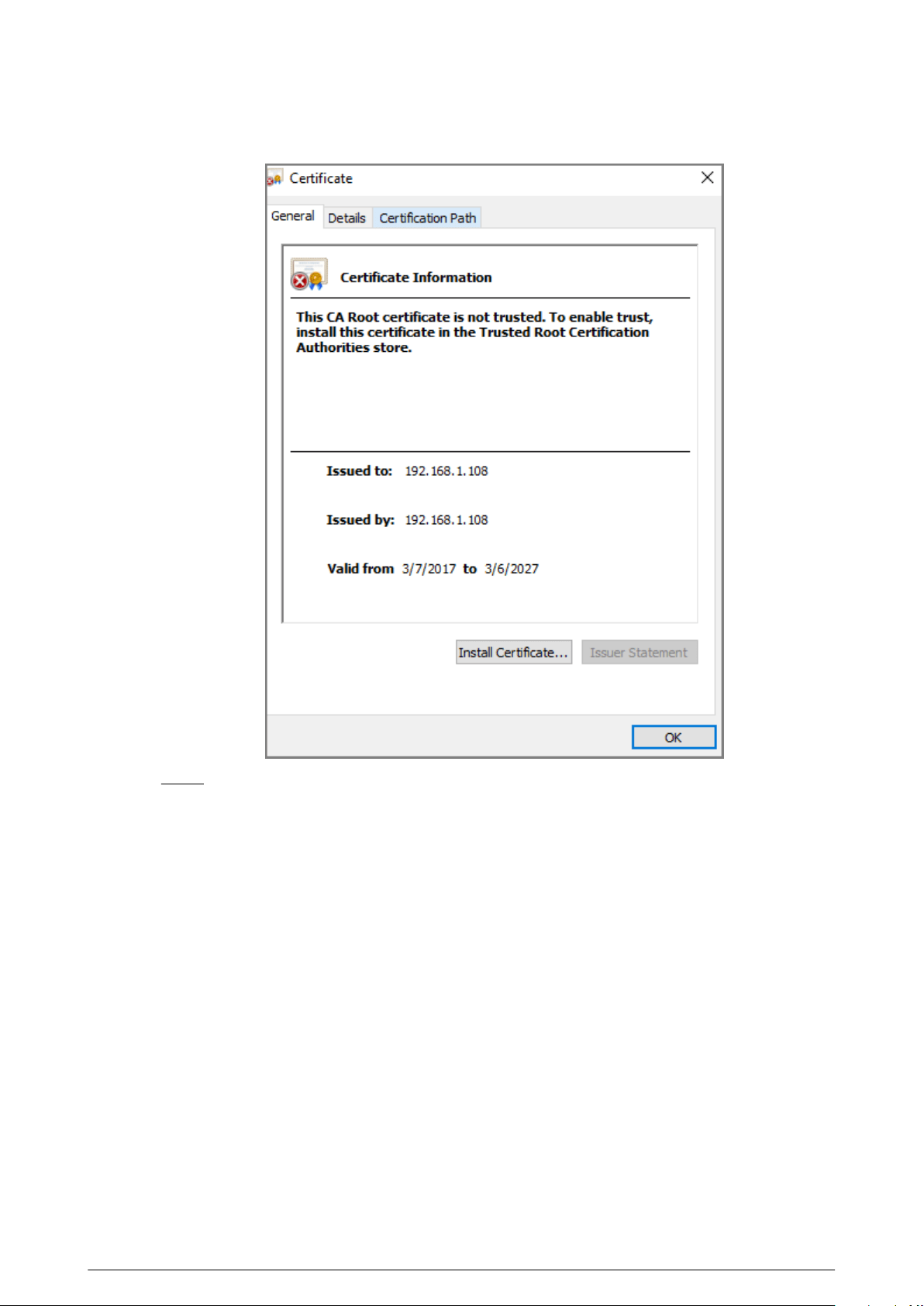
Figure 3-35 Certicate information
Step 4 Select Current User or Local Machine , and then click Next.
●
Current User : Applies to the user that has logged in to the computer.
●
Local Machine : Applies to all users that have logged in to the computer.
79
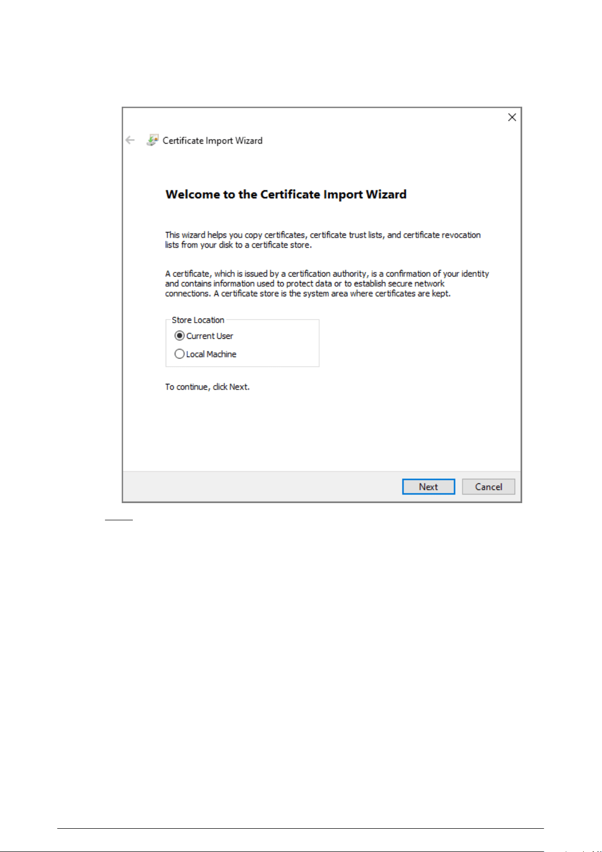
Figure 3-36 Store location
Step 5 Select the appropriate location.
a. Select Place all certicates in the following store.
b. Click Browse to import the certicate to the Trusted Root Certication Authorities
store , and then click Next.
80
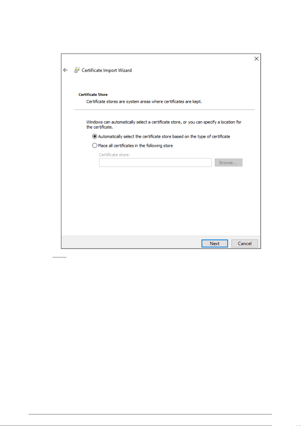
Figure 3-37 Certicate store
Step 6 Click Finish.
81
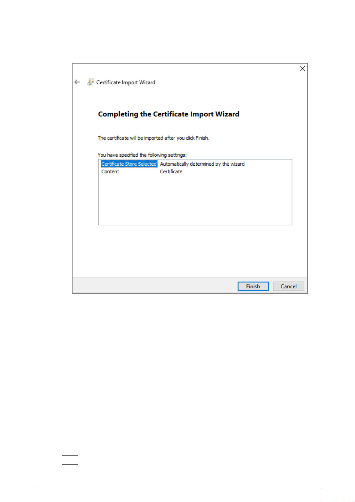
Figure 3-38 Finish downloading the certicate
3.9.2 Conguring UPnP Service
If the current VTO works as the SIP server, you can add mapping relationship between the intranet
and the extranet through UPnP protocol. This function enables you to connect devices in intranet
through extranet IP address.
Prerequisites
●
Make sure that the VTO has connected to the router.
●
Enable the UPnP function of the router, and then congure the WAN IP address to set up
internet connection.
●
Connect the VTO to the LAN port of the router.
3.9.2.1 Enabling the UPnP Services
Procedure
Step 1 Log in to the webpage.
Step 2 Select Network > UPnP .
82
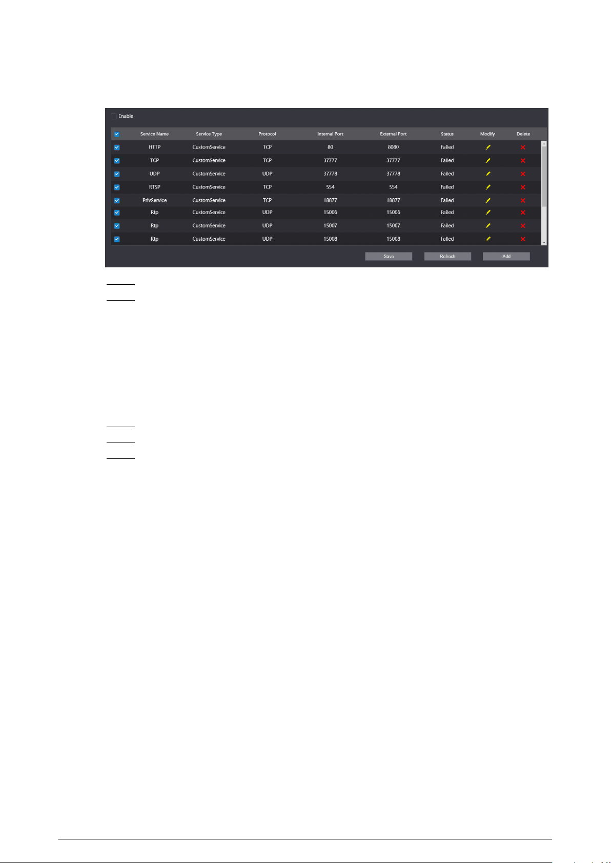
Figure 3-39 UPnP
Step 3 Select the services, and then select Enable.
Step 4 Click Save.
Enter http://extranet IP: external port to visit the internal device of the corresponding
port of the router.
3.9.2.2 Adding the UPnP Service
Add the new UPnP services.
Procedure
Step 1 Log in to the webpage.
Step 2 Select Network > UPnP .
Step 3 Click Add, and then congure the parameters.
83
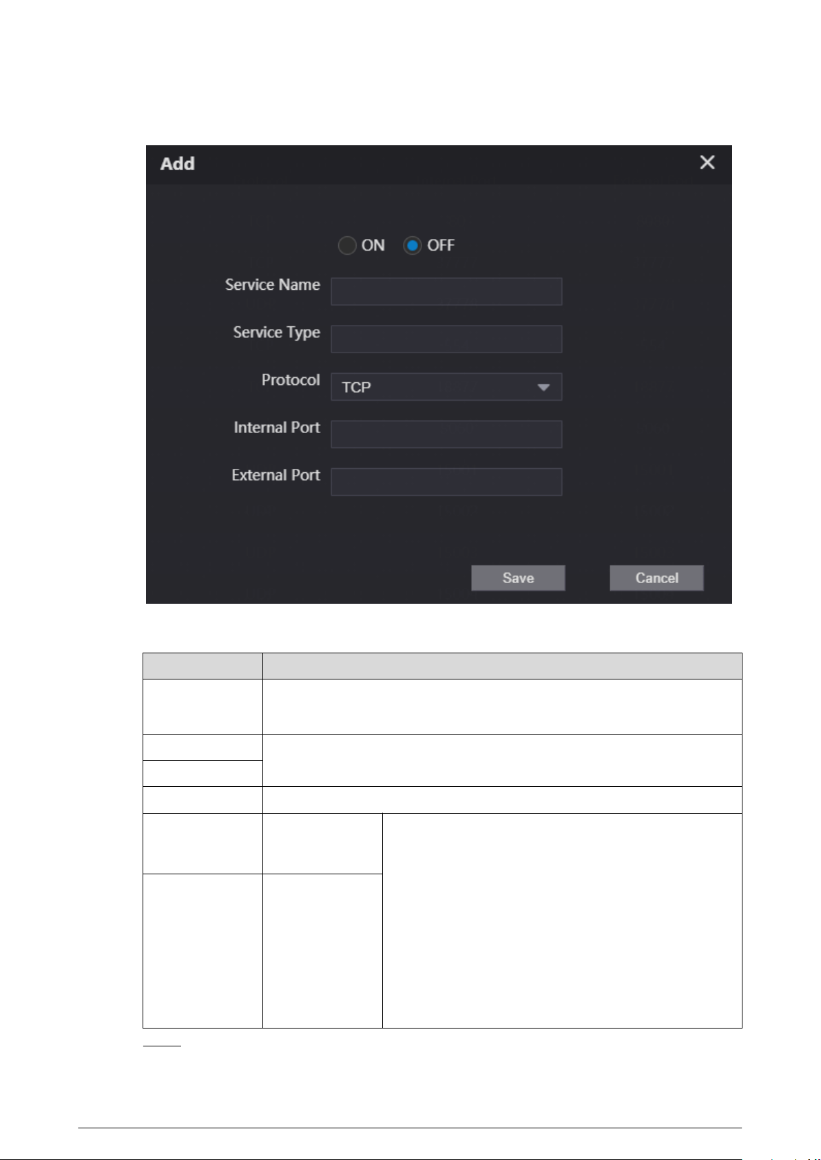
Figure 3-40 Add the UPnP service
Table 3-13 Description of UPnP service parameters
Parameter
Description
ON/OFF
●
ON : Enable the service.
●
OFF : Disable the service.
Service Name
The name and the type of the network service.
Service Type
Protocol Select from TCP and UDP.
Internal Port
The port that the
current VTO
needs to map.
●
We recommend you use the port number between
1024 to 5000 for the external port. Avoid the port
number between 1 to 255 and the system port
number between 256 to 1023 in case of port conicts.
●
If you deploy many devices on the same LAN, make
port number plan at rst to avoid many devices have
the mapping relationship with the same external port.
●
Make sure that the port number can work normally
and is not restricted.
●
The internal port and the external port of the TCP and
the UDP must be the same and cannot be modied.
External Port
The port of the
router that needs
to have the
mapping
relationship.
Step 4 Click Save.
84
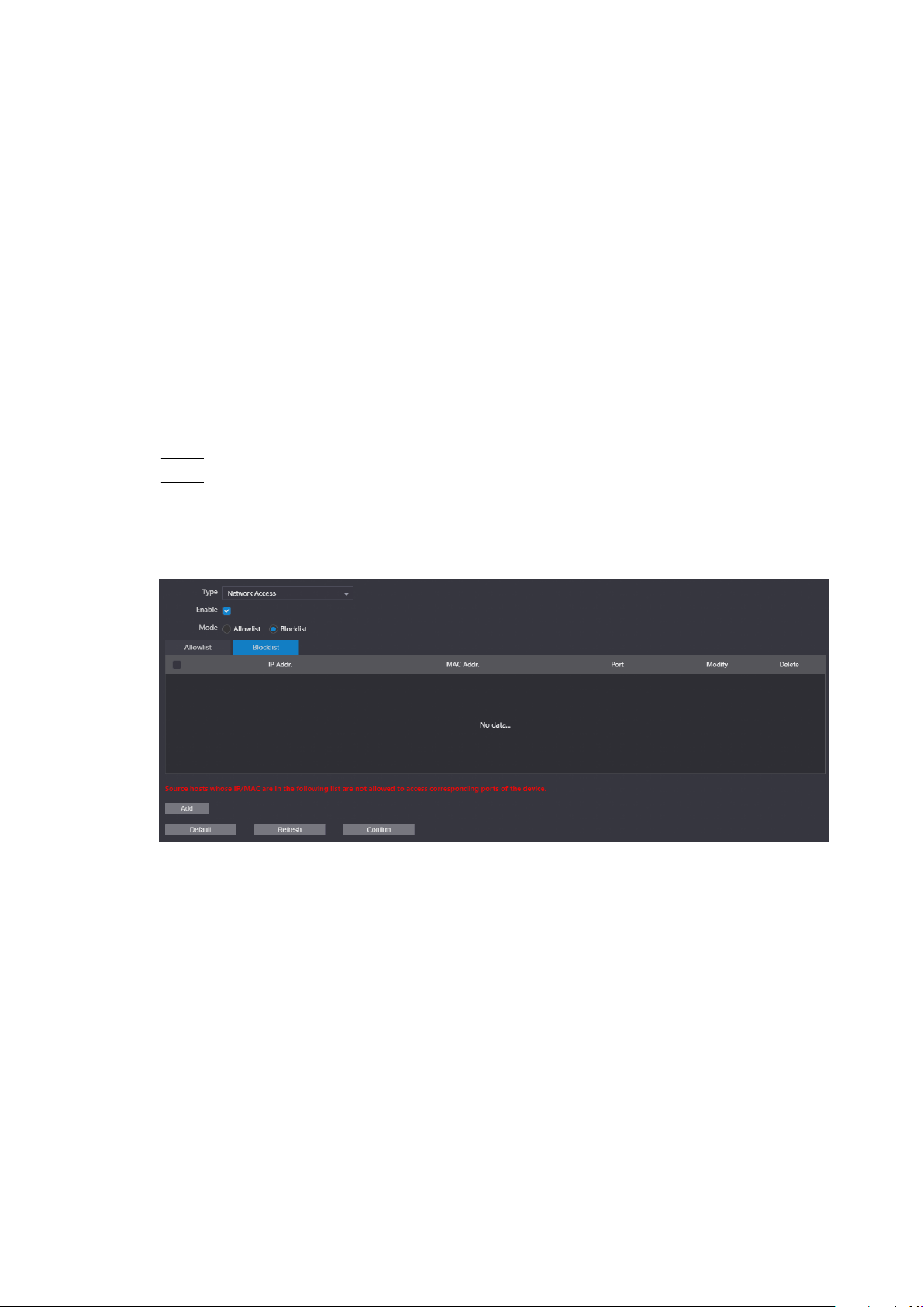
3.9.3 Conguring the SIP Server
Congure the SIP server and register the VTO and the VTH on the SIP server to enable the video
intercom through the SIP protocol. You can congure the current VTO, another VTO or the platform
as the SIP server. For details, see Video Door Phone_Quick Start Guide.
3.9.4 Firewall
3.9.4.1 Network Access
Congure the allowlist and the blocklist to manage the user permissions.
Procedure
Step 1 Log in to the webpage.
Step 2 Select Network > Firewall .
Step 3 Select Network Access as the type, and then select Enable.
Step 4 Congure the allowlist and the blocklist.
Figure 3-41 Network access
1. Select from Allowlist and Blocklist as the mode. You can also click Allowlist or
Blocklist tab.
2. Click Add.
3. Congure the parameters.
85
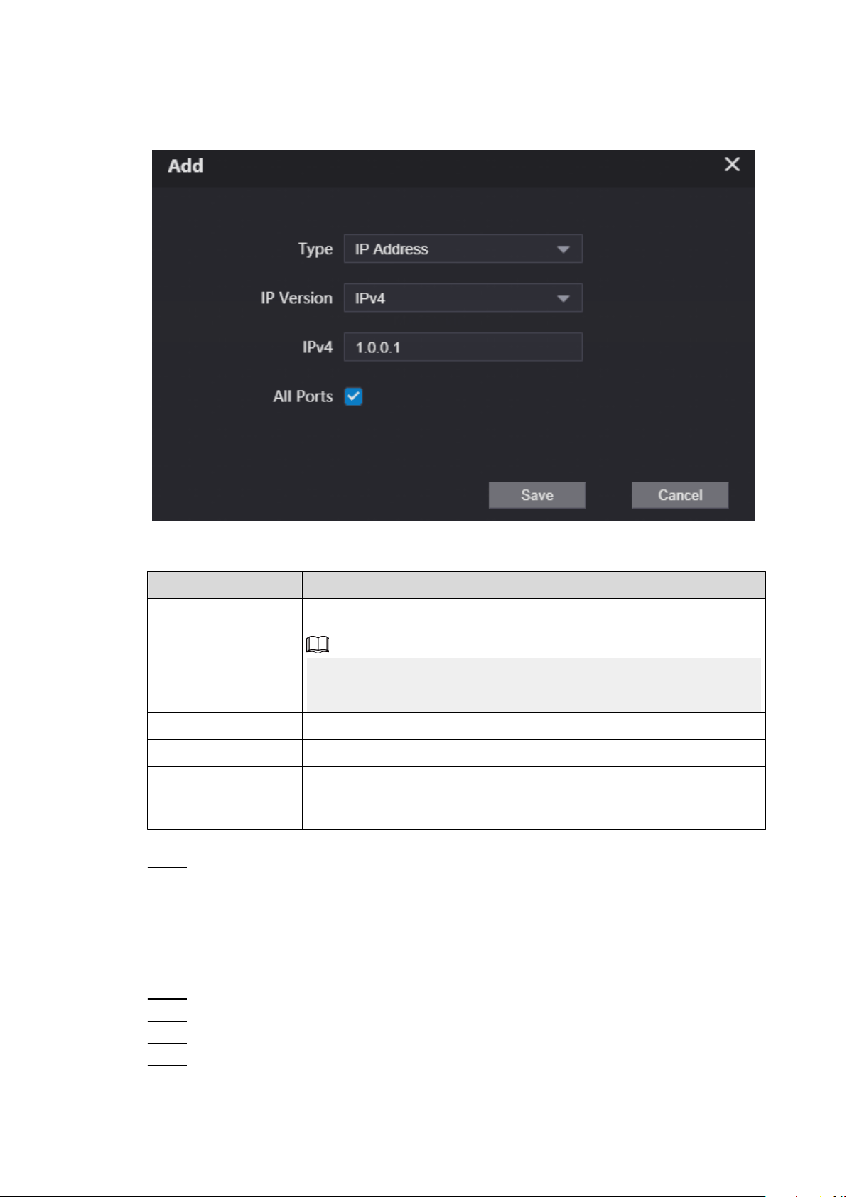
Figure 3-42 Add the IP address
Table 3-14 Parameters description of the IP address
Parameter
Description
Type
Select from IP Address , IP Section , MAC Addr. and All IP.
If you select MAC Addr. as the type, enter the MAC address, and then
click Save.
IP Version The default version is IPv4.
IPv4 Enter the IP address.
All Ports
After enabled, the allowlist or the blocklist will be applied to all ports of
the device. If you do not select all ports, enter the start port and the end
port.
4. Click Save.
Step 5 Click Conrm.
3.9.4.2 Prohibit PING
After enable Prohibit PING, the device will not answer the PING.
Procedure
Step 1 Log in to the webpage
Step 2 Select Network > Firewall .
Step 3 Select Prohibit PING as the type.
Step 4 Enable the function.
86
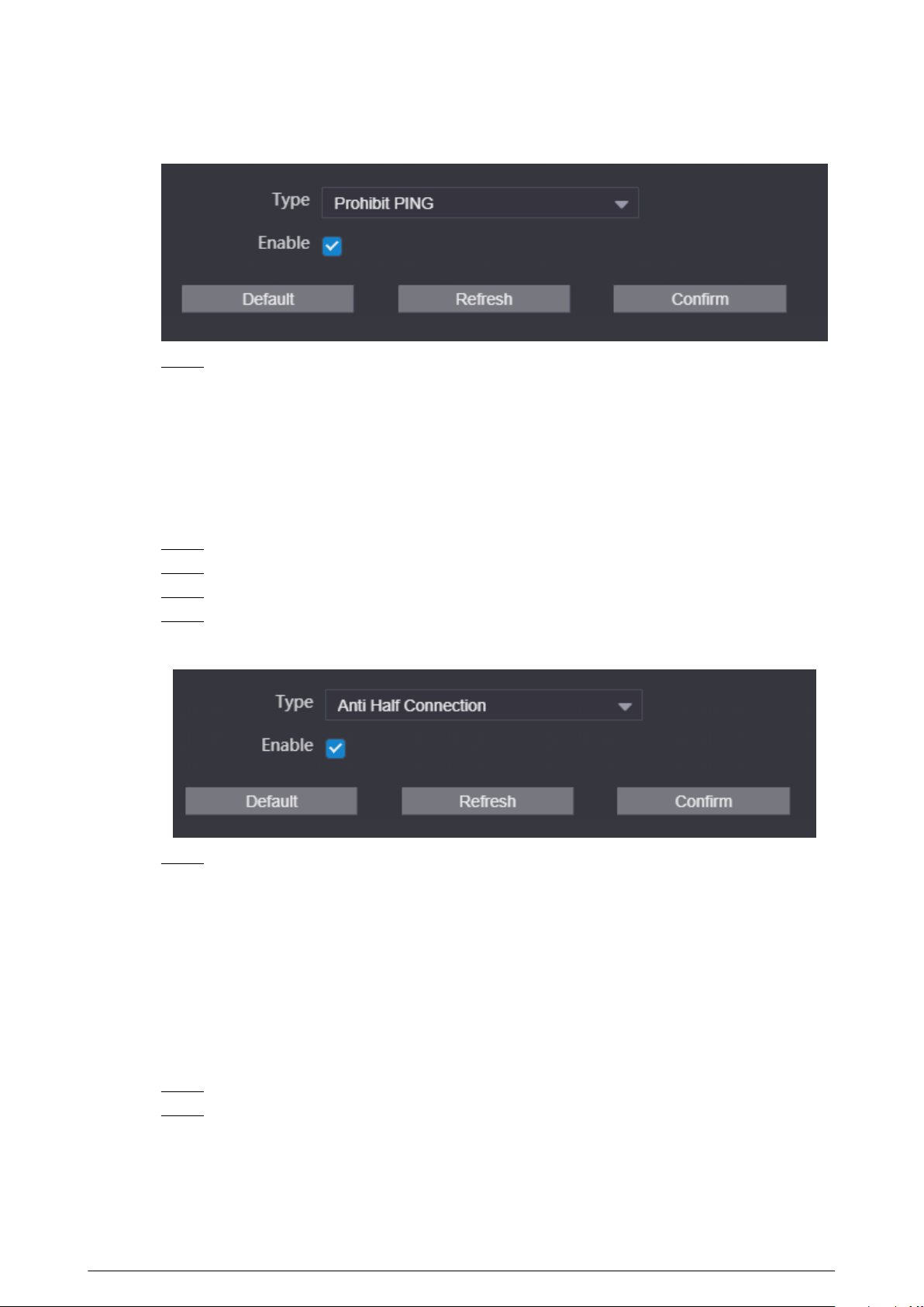
Figure 3-43 Prohibit PING
Step 5 Click Conrm.
3.9.4.3 Anti Half Connection
After enabled, the system monitors the UDP or TCP number that sends the request and dose not
receive the answer. The connection is not allowed when the number reached the certain value.
Make sure that the normal connection has the resource and the half-open connection is avoided.
Procedure
Step 1 Log in to the webpage.
Step 2 Select Network > Firewall .
Step 3 Select Anti Half Connection as the type.
Step 4 Enable the function.
Figure 3-44 Anti half connection
Step 5 Click Conrm.
3.10 Logs
3.10.1 Viewing the Call Records
View the call records of the VTO. The system can save up to 1,024 records.
Procedure
Step 1 Log in to the webpage.
Step 2 Select Search Log > Call .
87
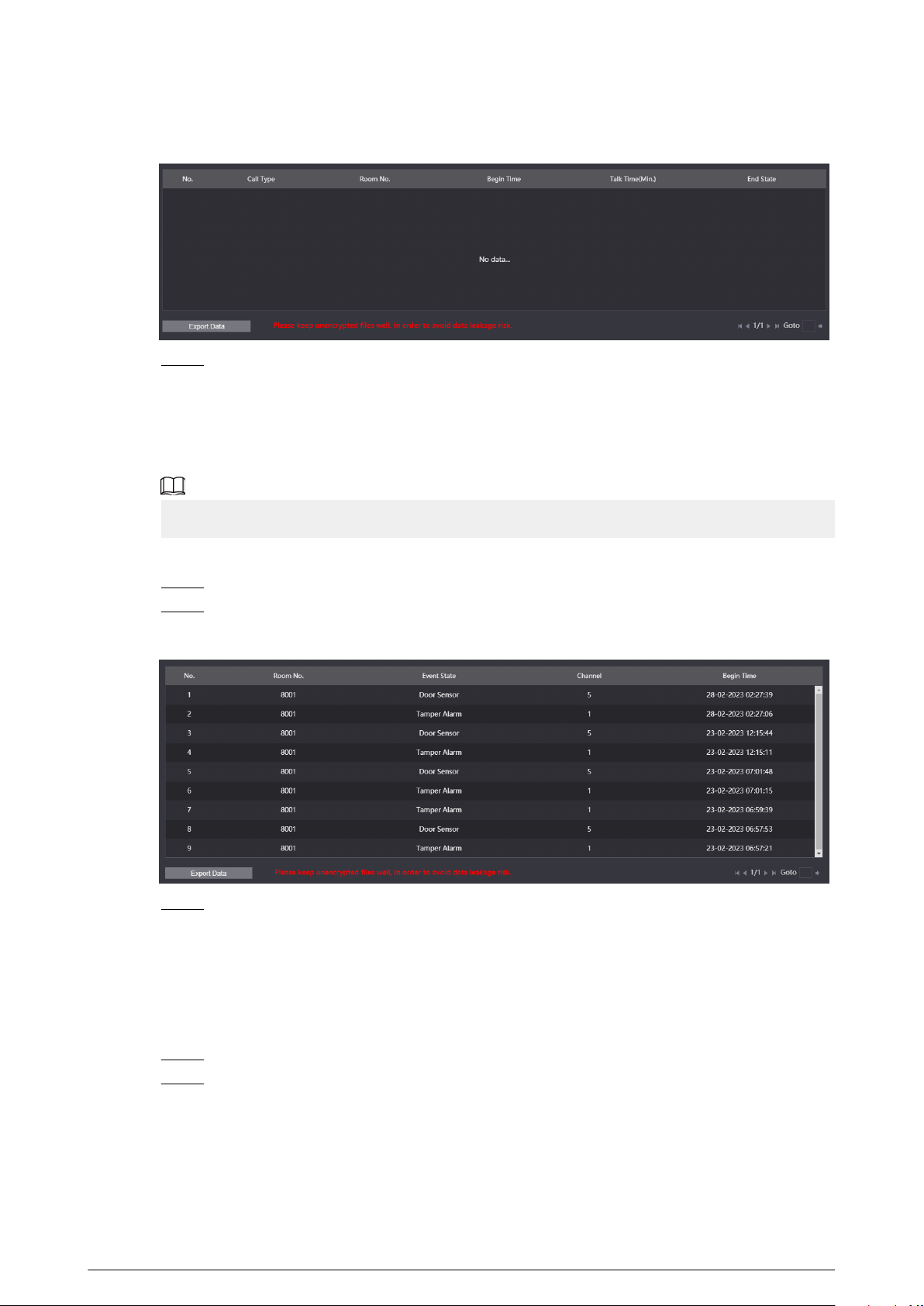
Figure 3-45 Call records
Step 3 (Optional) Click Export Data to export the call records of the VTO.
3.10.2 Searching the Alarm Records
View the alarm records of the VTO. The system can save up to 1,024 records.
When the current VTO works as the SIP server, the system has the alarm records.
Procedure
Step 1 Log in to the webpage.
Step 2 Select Search Log > Alarm .
Figure 3-46 Alarm records
Step 3 (Optional) Click Export Data to export the alarm records of the VTO.
3.10.3 Searching the Records of unlocking the door
View the records of unlocking the door. The system can save up to 1,024 records.
Procedure
Step 1 Log in to the webpage.
Step 2 Select Search Log > Unlock .
88
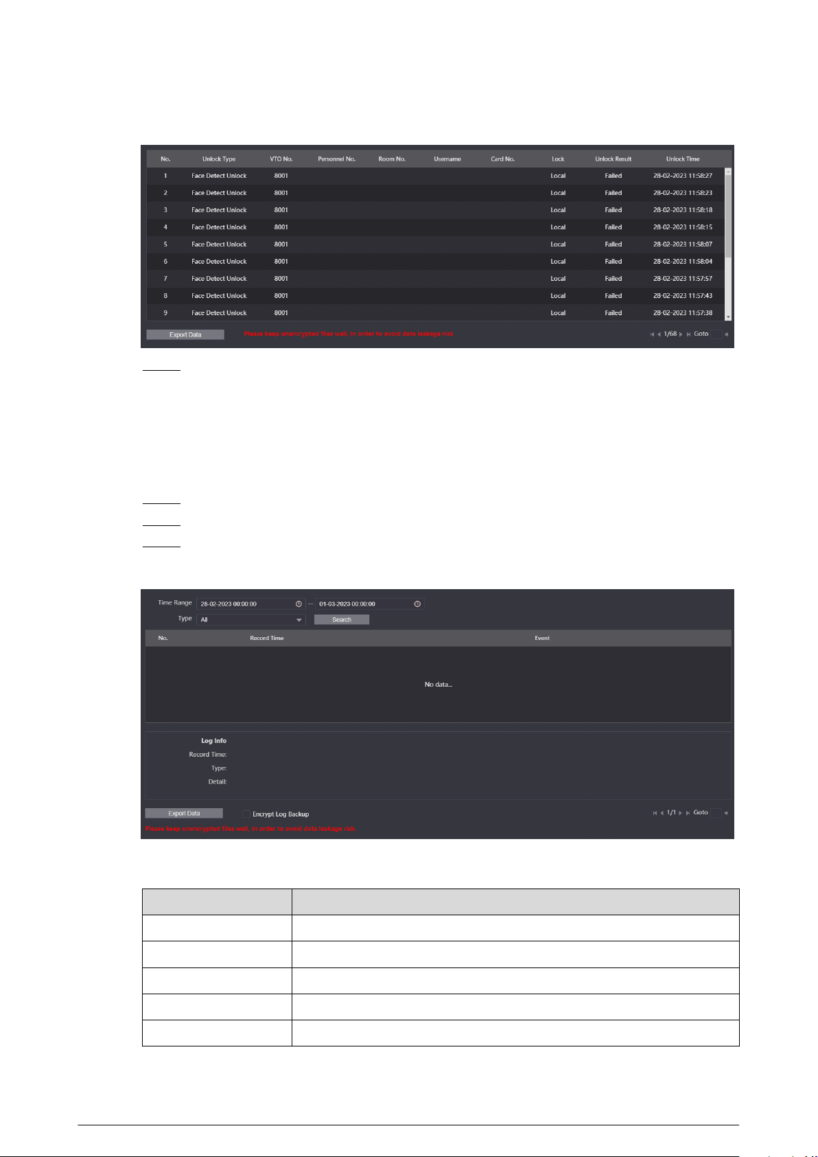
Figure 3-47 Records
Step 3 (Optional) Click Export Data to export the records of unlocking the door.
3.10.4 Searching the System Logs
View the operation logs of the webpage.
Procedure
Step 1 Log in to the webpage.
Step 2 Select Search Log > Log .
Step 3 Congure the time range, select the type, and then click Search to view the logs.
Figure 3-48 Logs
Table 3-15 Description of log type
Type
Description
All Search for all the logs.
System Search for the logs of the system.
Record Search for the operation logs of the record.
Cong Search for the logs of the conguration.
Account Search for the logging records of all the accounts.
89

Type Description
Security
Search for the logs of the system security, such as duress, anti-tampering
and power-o.
Event Search for the logs of the event, such as the alarm logs.
Step 4 (Optional) Click Export Data to export the logs.
3.11 Restarting the Device
Select > Reboot , and then click Conrm in the pop-up window. The device automatically
restarts, and the webpage goes to the login page.
3.12 Restoring to Factory Defaults
Select > Restore , and then click Conrm in the pop-up window. The device automatically
restarts and restores all the parameters to the defaults except the IP address, and the webpage
goes to the login page.
3.13 Logging Out
Select
> Exit . The webpage goes to the login page.
90

Appendix 1 Cybersecurity Recommendations
Mandatory actions to be taken for basic device network security:
1. Use Strong Passwords
Please refer to the following suggestions to set passwords:
●
The length should not be less than 8 characters.
●
Include at least two types of characters; character types include upper and lower case letters,
numbers and symbols.
●
Do not contain the account name or the account name in reverse order.
●
Do not use continuous characters, such as 123, abc, etc.
●
Do not use overlapped characters, such as 111, aaa, etc.
2. Update Firmware and Client Software in Time
●
According to the standard procedure in Tech-industry, we recommend to keep your device
(such as NVR, DVR, IP camera, etc.) rmware up-to-date to ensure the system is equipped
with the latest security patches and xes. When the device is connected to the public
network, it is recommended to enable the “auto-check for updates” function to obtain timely
information of rmware updates released by the manufacturer.
●
We suggest that you download and use the latest version of client software.
"Nice to have" recommendations to improve your device network security:
1. Physical Protection
We suggest that you perform physical protection to device, especially storage devices. For
example, place the device in a special computer room and cabinet, and implement well-done
access control permission and key management to prevent unauthorized personnel from
carrying out physical contacts such as damaging hardware, unauthorized connection of
removable device (such as USB ash disk, serial port), etc.
2. Change Passwords Regularly
We suggest that you change passwords regularly to reduce the risk of being guessed or cracked.
3. Set and Update Passwords Reset Information Timely
The device supports password reset function. Please set up related information for password
reset in time, including the end user’s mailbox and password protection questions. If the
information changes, please modify it in time. When setting password protection questions, it is
suggested not to use those that can be easily guessed.
4. Enable Account Lock
The account lock feature is enabled by default, and we recommend you to keep it on to
guarantee the account security. If an attacker attempts to log in with the wrong password
several times, the corresponding account and the source IP address will be locked.
5. Change Default HTTP and Other Service Ports
We suggest you to change default HTTP and other service ports into any set of numbers
between 1024–65535, reducing the risk of outsiders being able to guess which ports you are
using.
6. Enable HTTPS
We suggest you to enable HTTPS, so that you visit Web service through a secure communication
channel.
7. MAC Address Binding
We recommend you to bind the IP and MAC address of the gateway to the device, thus reducing
the risk of ARP spoong.
8. Assign Accounts and Privileges Reasonably
91

According to business and management requirements, reasonably add users and assign a
minimum set of permissions to them.
9. Disable Unnecessary Services and Choose Secure Modes
If not needed, it is recommended to turn o some services such as SNMP, SMTP, UPnP, etc., to
reduce risks.
If necessary, it is highly recommended that you use safe modes, including but not limited to the
following services:
●
SNMP: Choose SNMP v3, and set up strong encryption passwords and authentication
passwords.
●
SMTP: Choose TLS to access mailbox server.
●
FTP: Choose SFTP, and set up strong passwords.
●
AP hotspot: Choose WPA2-PSK encryption mode, and set up strong passwords.
10.Audio and Video Encrypted Transmission
If your audio and video data contents are very important or sensitive, we recommend that you
use encrypted transmission function, to reduce the risk of audio and video data being stolen
during transmission.
Reminder: encrypted transmission will cause some loss in transmission eciency.
11.Secure Auditing
●
Check online users: we suggest that you check online users regularly to see if the device is
logged in without authorization.
●
Check device log: By viewing the logs, you can know the IP addresses that were used to log
in to your devices and their key operations.
12.Network Log
Due to the limited storage capacity of the device, the stored log is limited. If you need to save
the log for a long time, it is recommended that you enable the network log function to ensure
that the critical logs are synchronized to the network log server for tracing.
13.Construct a Safe Network Environment
In order to better ensure the safety of device and reduce potential cyber risks, we recommend:
●
Disable the port mapping function of the router to avoid direct access to the intranet devices
from external network.
●
The network should be partitioned and isolated according to the actual network needs. If
there are no communication requirements between two sub networks, it is suggested to use
VLAN, network GAP and other technologies to partition the network, so as to achieve the
network isolation eect.
●
Establish the 802.1x access authentication system to reduce the risk of unauthorized access
to private networks.
●
Enable IP/MAC address ltering function to limit the range of hosts allowed to access the
device.
92