Video Door Phone
Quick Start Guide
V1.0.1
I
Foreword
This manual introduces the common configuration of intercom devices. Read carefully before using
the device, and keep the manual safe for future reference.
Safety Instructions
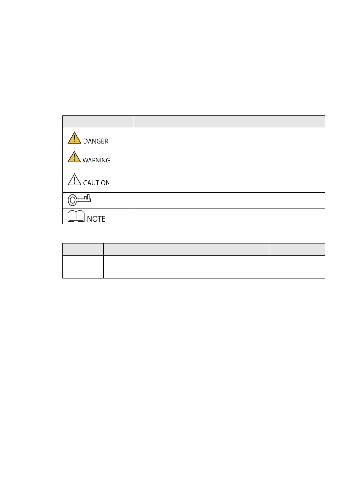
The following signal words might appear in the manual.
Signal Words Meaning
Indicates a high potential hazard which, if not avoided, will result in
death or serious injury.
Indicates a medium or low potential hazard which, if not avoided,
could result in slight or moderate injury.
Indicates a potential risk which, if not avoided, could result in property
damage, data loss, reductions in performance, or unpredictable
results.
Provides methods to help you solve a problem or save time.
Provides additional information as a supplement to the text.
Revision History
Version Revision Content Release Time
V1.0.1 Revised manual name. April 2023
V1.0.0 First release. January 2023
Privacy Protection Notice
As the device user or data controller, you might collect the personal data of others such as their face,
fingerprints, and license plate number. You need to be in compliance with your local privacy
protection laws and regulations to protect the legitimate rights and interests of other people by
implementing measures which include but are not limited: Providing clear and visible identification
to inform people of the existence of the surveillance area and provide required contact information.
About the Manual
●
The manual is for reference only. Slight differences might be found between the manual and the
product.
●
We are not liable for losses incurred due to operating the product in ways that are not in
compliance with the manual.
●
The manual will be updated according to the latest laws and regulations of related jurisdictions.
For detailed information, see the paper user’s manual, use our CD-ROM, scan the QR code or visit
our official website. The manual is for reference only. Slight differences might be found between
the electronic version and the paper version.
●
All designs and software are subject to change without prior written notice. Product updates
might result in some differences appearing between the actual product and the manual. Please
contact customer service for the latest program and supplementary documentation.

II
●
There might be errors in the print or deviations in the description of the functions, operations
and technical data. If there is any doubt or dispute, we reserve the right of final explanation.
●
Upgrade the reader software or try other mainstream reader software if the manual (in PDF
format) cannot be opened.
●
All trademarks, registered trademarks and company names in the manual are properties of their
respective owners.
●
Please visit our website, contact the supplier or customer service if any problems occur while
using the device.
●
If there is any uncertainty or controversy, we reserve the right of final explanation.
III
Important Safeguard and Warnings
This section introduces content covering the proper handling of the device, hazard prevention, and
prevention of property damage. Read carefully before using the device, and comply with the
guidelines when using it.
Operation Requirements
●
Check whether the power supply is correct before use.
●
Do not unplug the power cord on the side of the device while the adapter is powered on.
●
Operate the device within the rated range of power input and output.
●
Transport, use and store the device under allowed humidity and temperature conditions.
●
If the device is powered off for longer than a month, it should be placed in its original package
and sealed. Make sure to keep it away from moisture, and store it under allowed humidity and
temperature conditions.
●
Do not drop or splash liquid onto the device, and make sure that there is no object filled with
liquid on the device to prevent liquid from flowing into it.
●
Do not disassemble the device without professional instruction.
Installation Requirements
●
Do not connect the power adapter to the device while the adapter is powered on.
●
Strictly comply with the local electric safety code and standards. Make sure the ambient voltage
is stable and meets the power supply requirements of the device.
●
Do not connect the device to two or more kinds of power supplies, to avoid damage to the
device.
●
Improper use of the battery might result in a fire or explosion.
●
Personnel working at heights must take all necessary measures to ensure personal safety
including wearing a helmet and safety belts.
●
Do not place the device in a place exposed to sunlight or near heat sources.
●
Keep the device away from dampness, dust, and soot.
●
Install the device on a stable surface to prevent it from falling.
●
Install the device in a well-ventilated place, and do not block its ventilation.
●
Use an adapter or cabinet power supply provided by the manufacturer.
●
Use the power cords that are recommended for the region and conform to the rated power
specifications.
●
The power supply must conform to the requirements of ES1 in IEC 62368-1 standard and be no
higher than PS2. Please note that the power supply requirements are subject to the device label.
●
The device is a class I electrical appliance. Make sure that the power supply of the device is
connected to a power socket with protective earthing.

IV
Table of Contents
Foreword
........................................................................................................................................................................................................I
Important Safeguard and Warnings
.............................................................................................................................................. III
1 Common Configuration
.................................................................................................................................................................... 1
1.1 Basic Configuration Procedure
........................................................................................................................................... 1
1.2 Preparation
................................................................................................................................................................................... 2
2 VTO Configuration
............................................................................................................................................................................... 3
2.1 Initialization
................................................................................................................................................................................. 3
2.2 Configuring the VTO Number
.............................................................................................................................................. 4
2.3 Configuring Network Parameters
..................................................................................................................................... 5
2.4 Configuring the SIP Server
.................................................................................................................................................... 5
2.4.1 VTO as the SIP Server
.................................................................................................................................................... 6
2.4.2 Platform (DSS Express/DSS Pro) as the SIP Server
......................................................................................... 7
2.5 Configuring Call Number and Group Call
...................................................................................................................... 8
2.6 Adding VTOs
................................................................................................................................................................................ 8
2.7 Adding Room Numbers
........................................................................................................................................................ 10
3 VTH Configuration
............................................................................................................................................................................. 12
3.1 Quick Configuration
............................................................................................................................................................... 12
3.2 Manual Configuration
........................................................................................................................................................... 16
3.2.1 Configuring Network Parameters
........................................................................................................................ 16
3.2.1.1 LAN
............................................................................................................................................................................ 16
3.2.1.2 WLAN
........................................................................................................................................................................ 17
3.2.2 Configuring the SIP Server
....................................................................................................................................... 18
3.2.3 Configuring the VTH
................................................................................................................................................... 19
3.2.4 Configuring the VTO
................................................................................................................................................... 20
3.2.4.1 Adding the Main VTO
....................................................................................................................................... 21
3.2.4.2 Adding the Sub VTO
......................................................................................................................................... 21
4 Commissioning
.................................................................................................................................................................................... 22
4.1 Using the VTO to Call the VTH
........................................................................................................................................... 22
4.2 Using the VTH to Monitor the VTO
................................................................................................................................. 22
Appendix 1 Cybersecurity Recommendations
........................................................................................................................ 24
1
1 Common Configuration
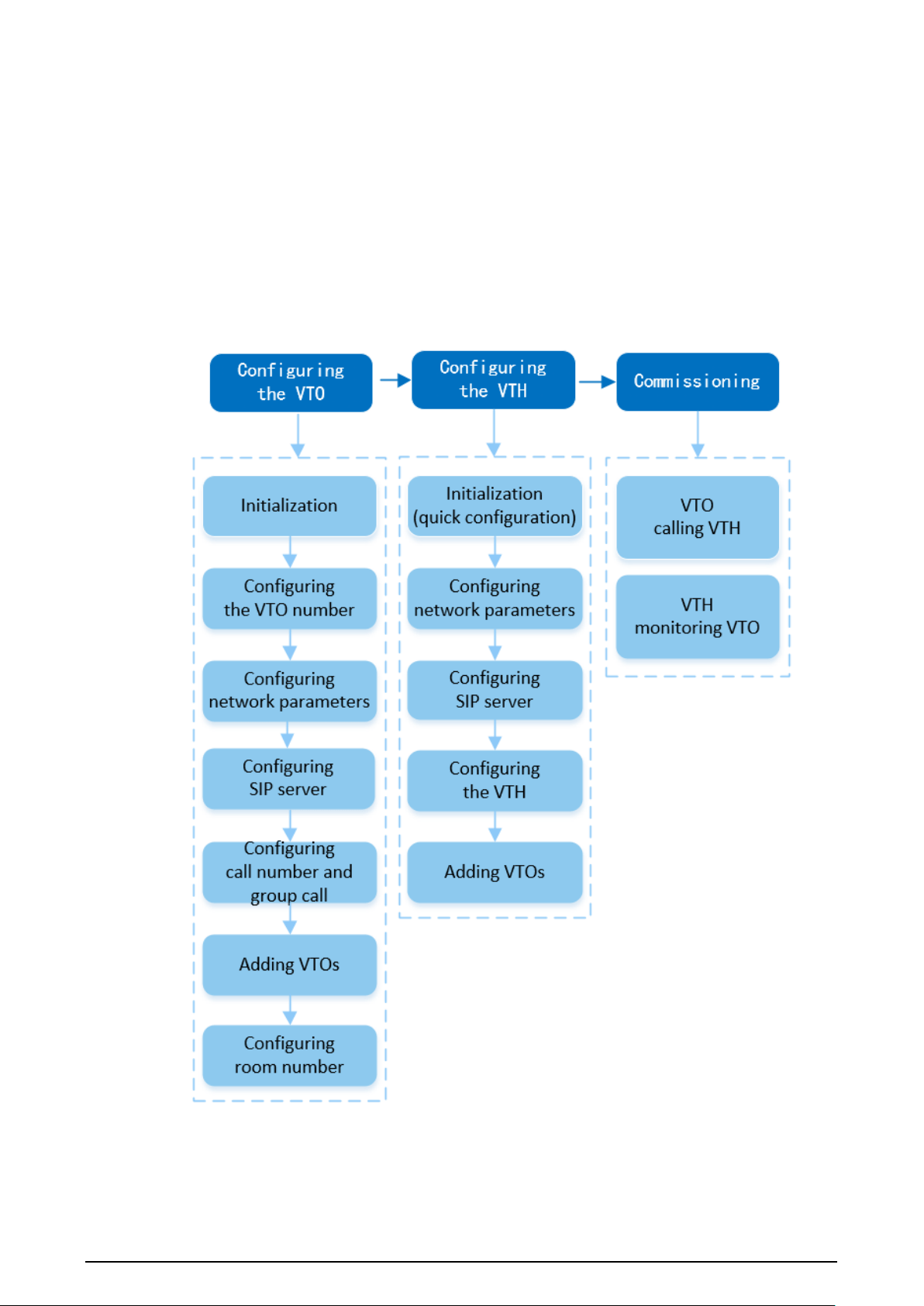
Follow the configuration procedure and carry out commissioning to ensure that the device can
realize basic network access, call and monitoring functions.
1.1 Basic Configuration Procedure
Figure 1-1 Basic configuration procedure

2
1.2 Preparation
Before the configuration:
●
Make sure that there are no short or open circuit in the VTO and VTH.
●
Plan IP addresses and numbers (works as phone numbers) for every VTO and VTH.
●
Make sure that the VTH and VTO are on the same network segment.
3
2 VTO Configuration
2.1 Initialization
For first-time login, you need to initialize the VTO.
Prerequisites
Make sure that the computer and the VTO are on the same network segment.
Procedure
Step 1 Turn on the VTO.
Step 2 Enter the IP address of the VTO in the browser.
For first-time login, enter the default IP (192.168.1.108). If you have multiple VTOs, we
recommend you change the default IP address to avoid a conflict.
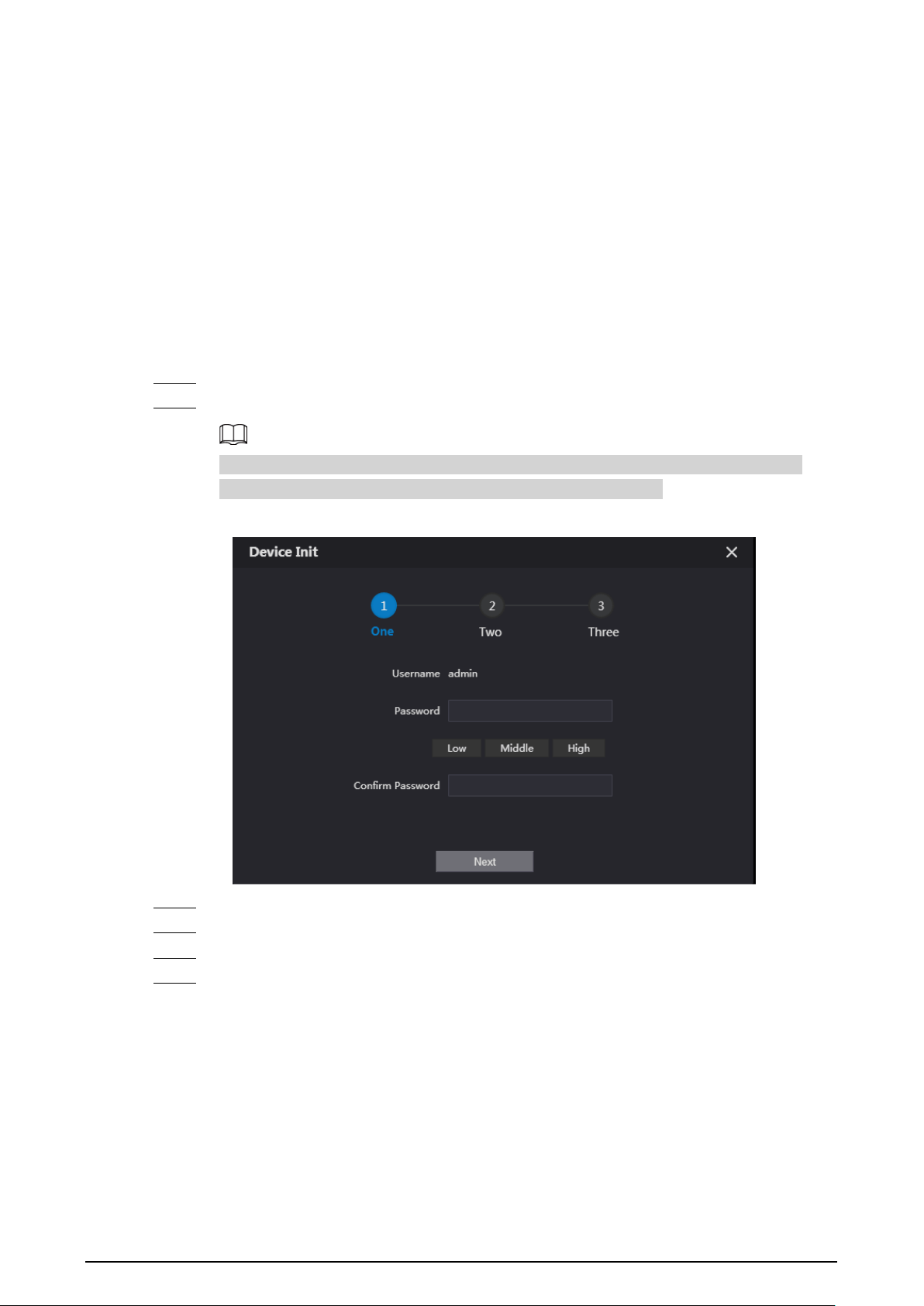
Figure 2-1 Device initialization
Step 3 Enter and confirm the new password, and then click
Next
.
Step 4 Select
Email
and enter the email address to use to reset your password.
Step 5 Click
Next
, and then click
OK
to go to the login page.
Step 6 Enter username and the new password to log in to the webpage.
4
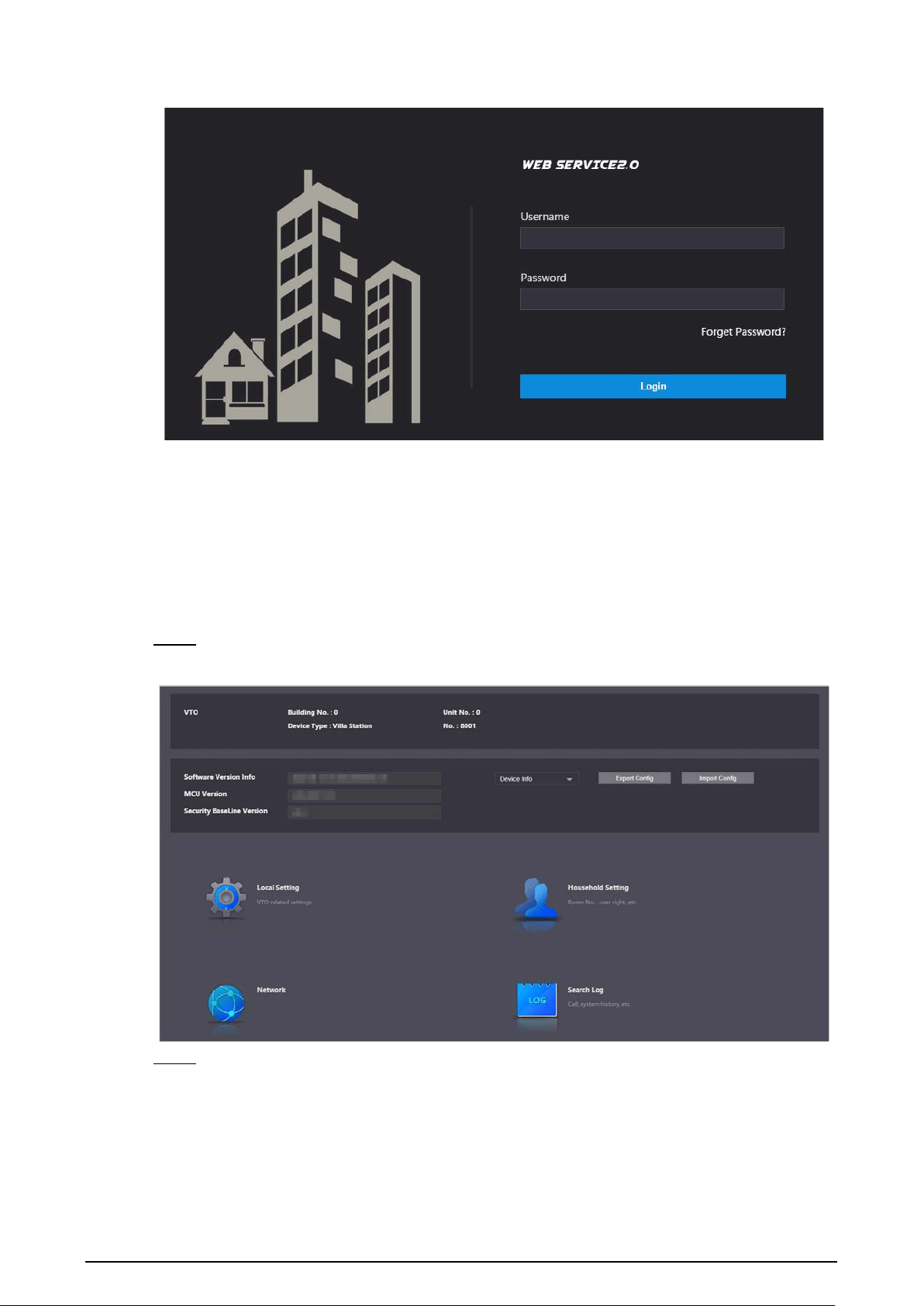
Figure 2-2 Login page
2.2 Configuring the VTO Number
Numbers can be used to distinguish each VTO. We recommend you set it according to the unit and
building number.
Procedure
Step 1 Log in to the webpage of the VTO.
Figure 2-3 Home page
Step 2 Select
Local Settings
>
Basic
.
5
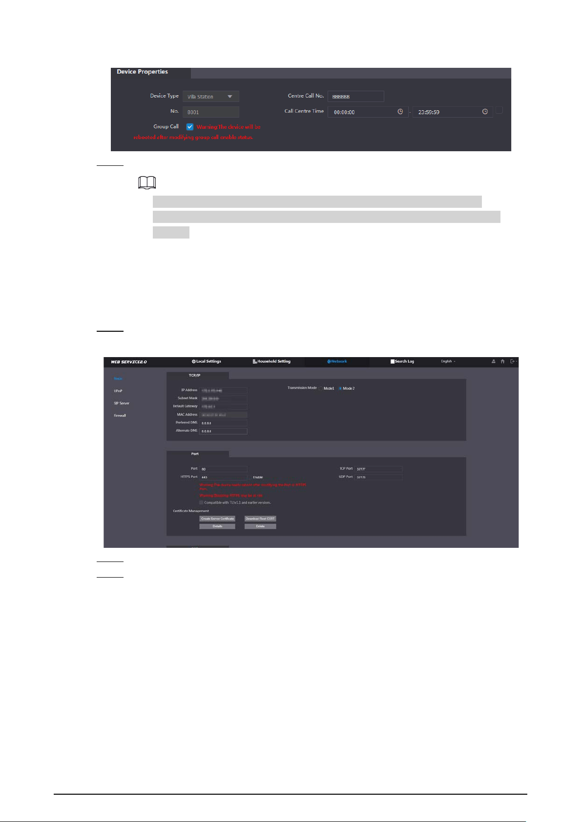
Figure 2-4 Device properties
Step 3 Enter the number of the VTO, and then click
Confirm
.
●
You can change the number of a VTO when it is not working as the SIP server.
●
A VTO number can contain up to 5 digits, and it cannot be the same as any room
number.
2.3 Configuring Network Parameters
Procedure
Step 1 Select
Network
>
Basic
.
Figure 2-5 TCP/IP information
Step 2 Enter the parameters, and then click
Save
.
Step 3 The VTO will automatically restart. You need to add the IP address of your computer to the
same network segment as the VTO to log in again.
2.4 Configuring the SIP Server
When connected to the same SIP server, all the VTOs and VTHs can call each other. You can use a
VTO or another server as the SIP server.
6
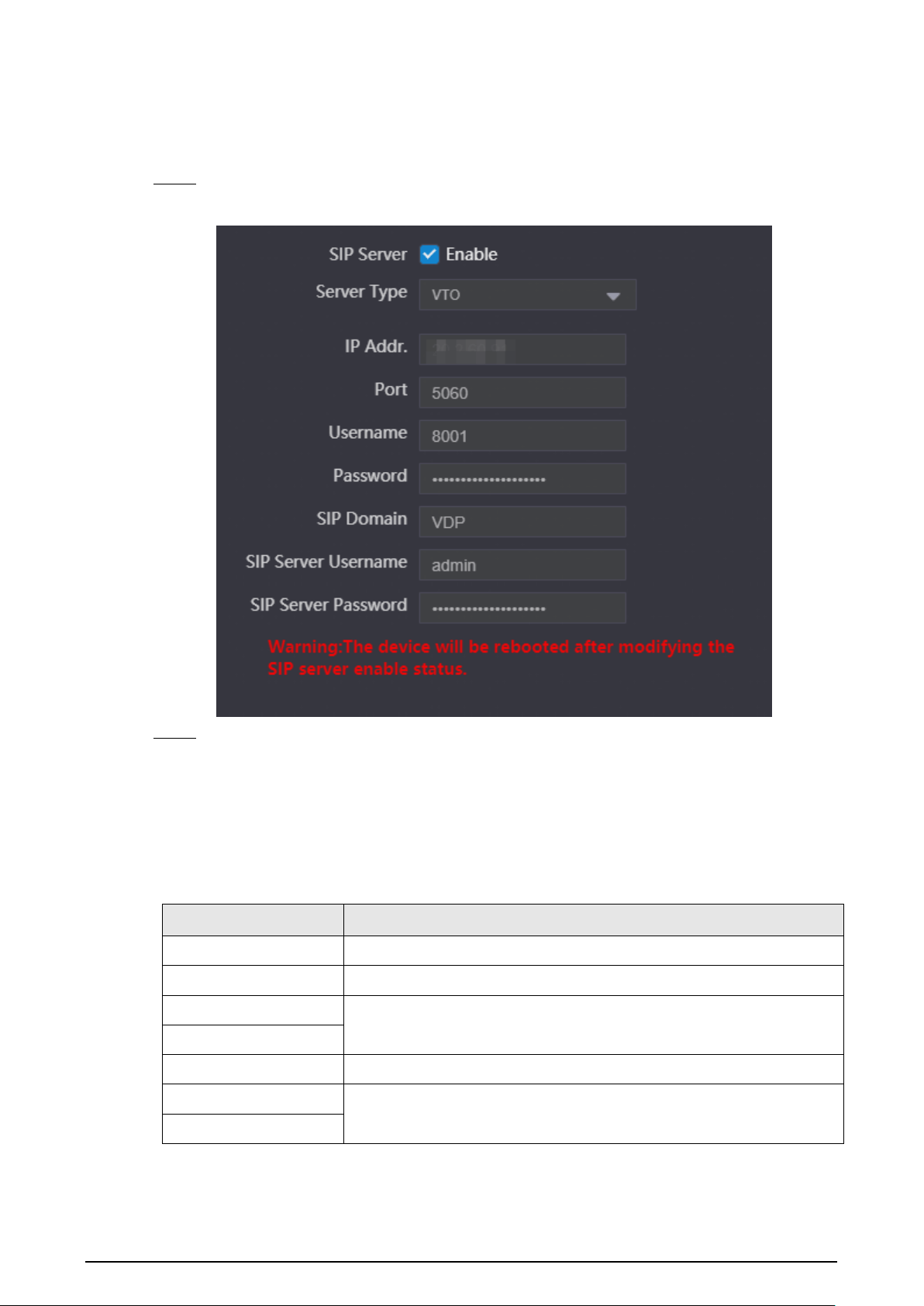
2.4.1 VTO as the SIP Server
Procedure
Step 1 Select
Network
>
SIP Server
.
Figure 2-6 VTO as the SIP server
Step 2 Configure the parameters.
●
If the current VTO works as the SIP server, enable
SIP Server
, and then click
Save
.
The VTO will automatically restart, and then you can add other VTOs and VTHs to this
VTO.
●
If another VTO is working as the SIP server, set
Server Type
as
VTO
, configure the
parameters, and then click
Save
.
Table 2-1 SIP server configuration
Parameter Description
IP Addr. The IP address of the VTO that works as the SIP server.
Port 5060 by default when the VTO works as an SIP server.
Username
Default.
Password
SIP Domain Default.
SIP Server Username
The username and password of the SIP server.
SIP Server Password
7
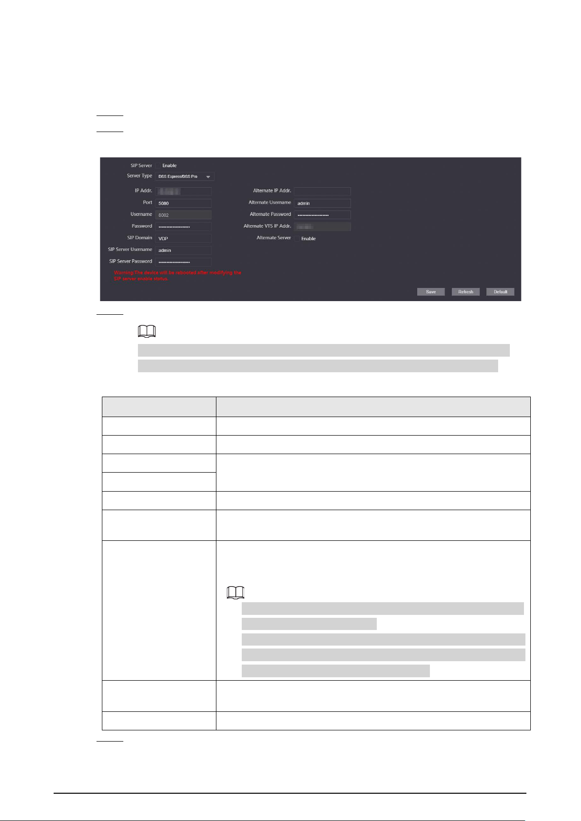
2.4.2 Platform (DSS Express/DSS Pro) as the SIP Server
Procedure
Step 1 Select
Network
>
SIP Server
.
Step 2 Enable
SIP Server
, and then set
Server Type
as
DSS Express/DSS Pro
.
Figure 2-7 Platform as the SIP server
Step 3 Configure the parameters.
When the platform is working as the SIP server and you want to configure the building
number and building unit number, enable
Support Building
and
Support Unit
first.
Table 2-2 SIP server configuration
Parameter Description
IP Addr. The IP address of the SIP server.
Port 5080 by default when the platform works as the SIP server.
Username
Default.
Password
SIP Domain Keep default value VDP or leave it empty.
SIP Server
Username/Password
The username and password of the SIP server.
Alternate IP Addr.
The alternate server will be used as the SIP server when DSS
Express/DSS pro stops responding We recommend you configure the
alternate IP address.
●
If you enable
Alternate Server
, the current VTO you have logged
in serves as the alternate server.
●
If you want another VTO serve as the alternate server, you need to
enter the IP address of that VTO in the
Alternate IP Addr.
textbox.
Do not enable
Alternate Server
in this case.
Alternate
Username/Password
Used to log in to the alternate server.
Alternate VTS IP Addr. IP address of the alternate VTS.
Step 4 Click
Save
.
8
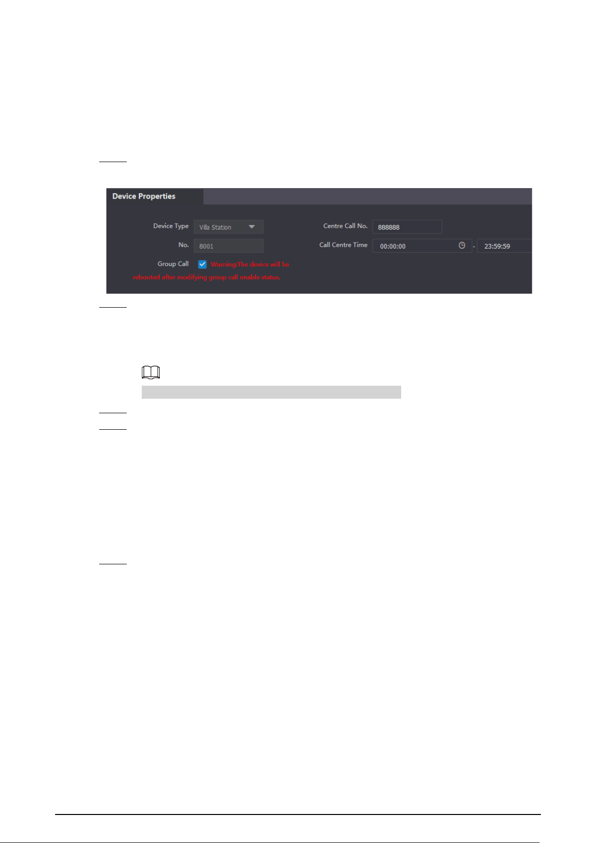
2.5 Configuring Call Number and Group Call
To dial and call a VTO, you need to configure the call number on each VTO that works as the phone
number.
Procedure
Step 1 Select
Local Settings
>
Basic
.
Figure 2-8 Device properties
Step 2 Enter the room number you need to call, and then click
Confirm
to save. Repeat this
operation on every villa door station (VTO) webpage.
On the SIP server, you can enable the group call function. When calling a main VTH, all
extension VTHs will also receive the call.
The VTO will restart after
Group Call
is enabled or disabled.
Step 3 Log in to the SIP server web page, and then select
Local Settings
>
Basic
.
Step 4 Enable
Group Call
, click
Confirm
, and then the VTO will restart.
2.6 Adding VTOs
You can add VTOs to the SIP server, which will allow all the VTOs connected to the same SIP server to
make video calls with one another. This section is for when a VTO is set as the SIP server.
Procedure
Step 1 Log in to the webpage of the SIP server, and then select
Household Setting
>
VTO No.
Management
.
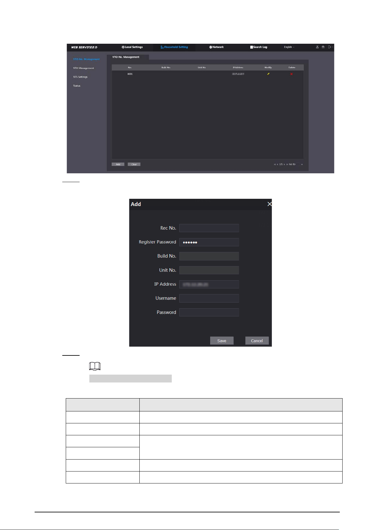
9
Figure 2-9 VTO number management
Step 2 Click
Add
.
Figure 2-10 Add a VTO
Step 3 Configure the parameters.
The SIP server must be added.
Table 2-3 Add door stations (VTO)
Parameter Description
Rec No. VTO number.
Register Password Default.
Build No.
Only available when the server is set as the SIP server.
Unit No.
IP Address VTO IP address.
Username The username and password of the webpage of the VTO.
10
Parameter Description
Password
Step 4 Click
Save
.
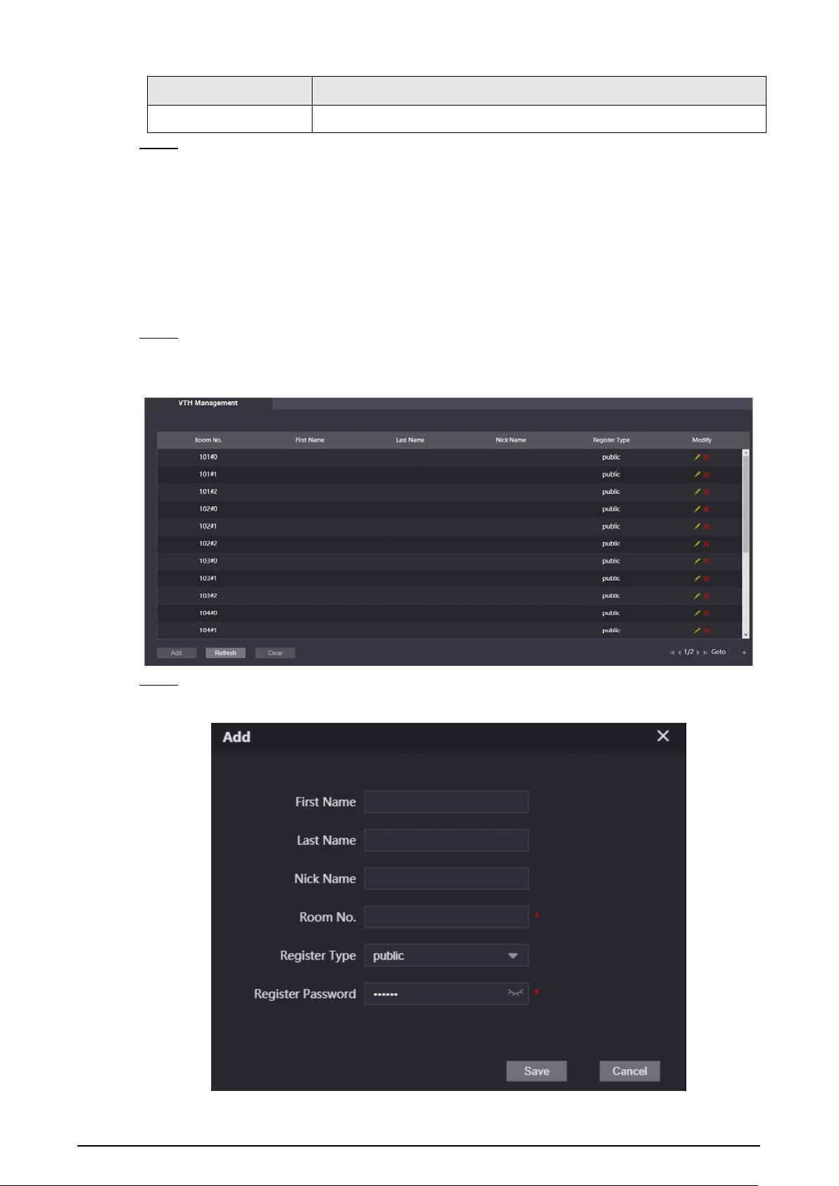
2.7 Adding Room Numbers
You can add room numbers to the SIP server, and then configure the room numbers on the VTHs to
connect them to the network. This section is for when a VTO is set as the SIP server.
Procedure
Step 1 Log in to the webpage of the SIP server, and then select
Household Setting
>
VTH
Management
to add the room number.
Figure 2-11 VTH management
Step 2 Click
Add
.
Figure 2-12 Add a single room number
11
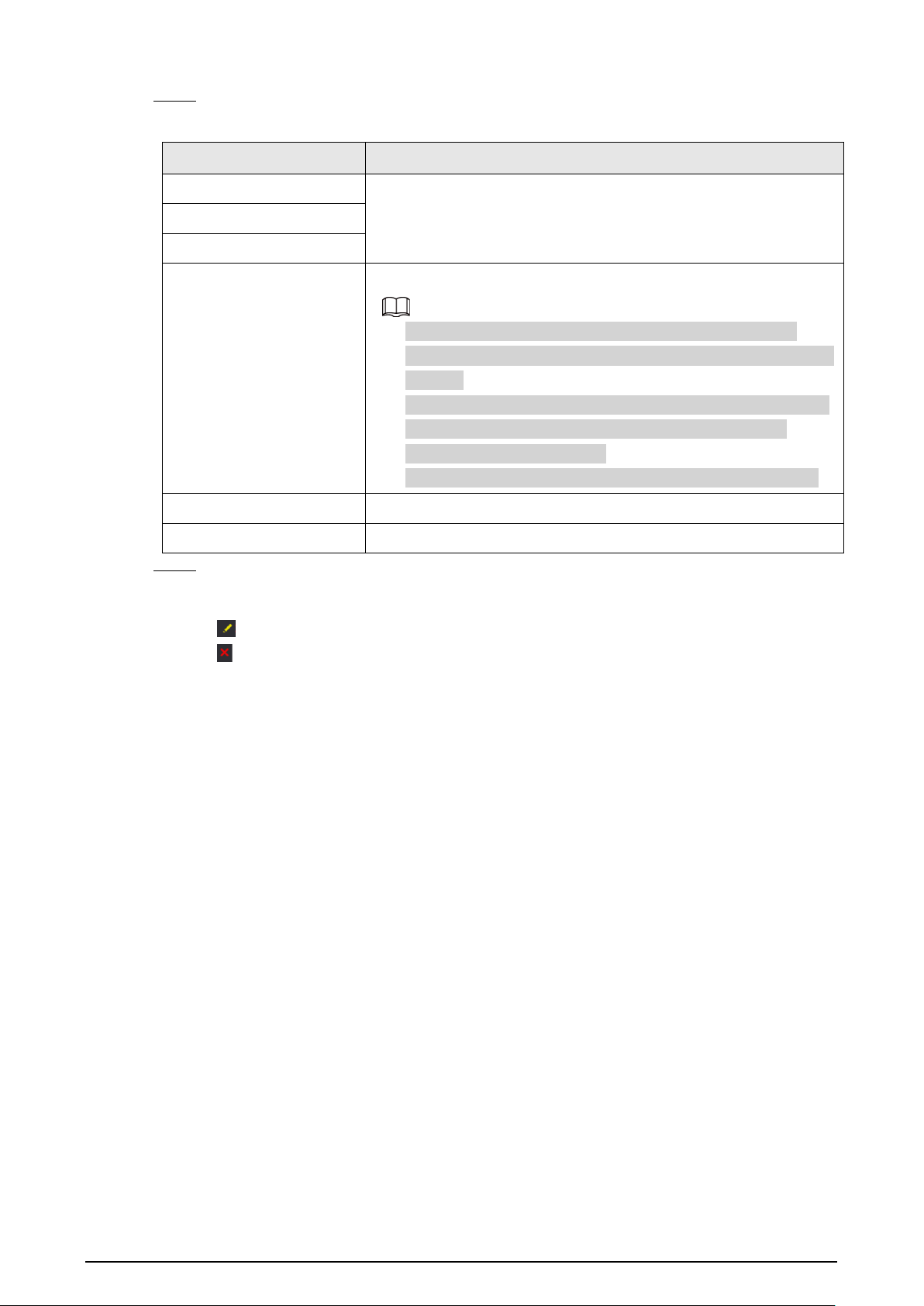
Step 3 Configure room information.
Table 2-4 Room information
Parameter Description
First Name
Information used to differentiate each room.
Last Name
Nick Name
Room No.
Room number.
●
The room number consists of up to 6 characters, and can
contain numbers and letters. It cannot be the same as the VTO
number.
●
When there are multiple VTHs, the room number for the main
VTH should end with #0, and the room numbers for the
extension VTHs with #1, #2….
●
You can configure up to 9 extension VTHs for each main VTH.
Registration Mode
Select
public
.
Registered Password Default.
Step 4 Click
Save
.
Related Operations
●
Click to modify room information.
●
Click to delete the room.
12
3 VTH Configuration
This chapter introduces how to configure the VTH and use the intercom function.
3.1 Quick Configuration
For first-time login, you can quickly initialize and configure the VTH through quick configuration.
Background Information
Quick configuration enables you to configure the parameters of the VTO, VTH and the SIP server at
the same time. For more details about modifying the parameters, see "3.2 Manual Configuration".
Procedure
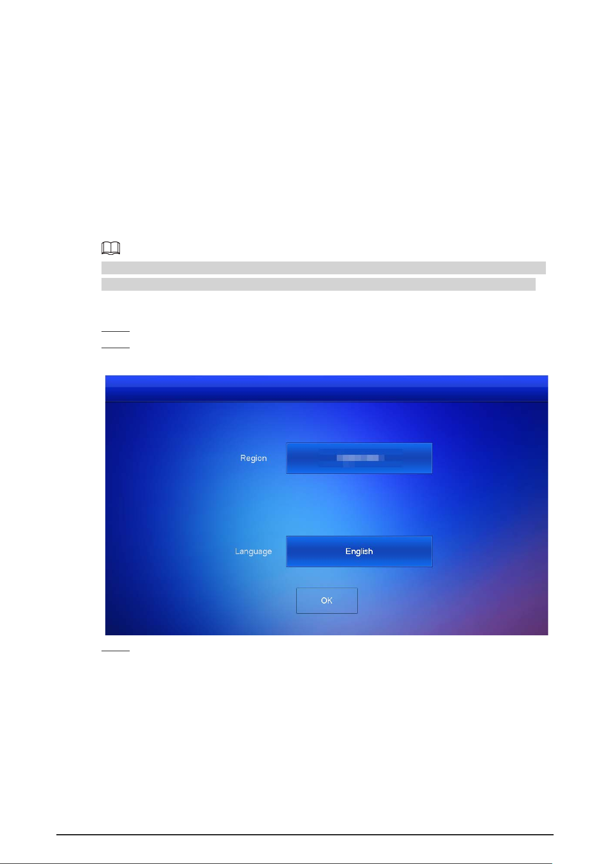
Step 1 Turn on the VTH.
Step 2 Select a region and language, and then tap
OK
.
Figure 3-1 Region and language
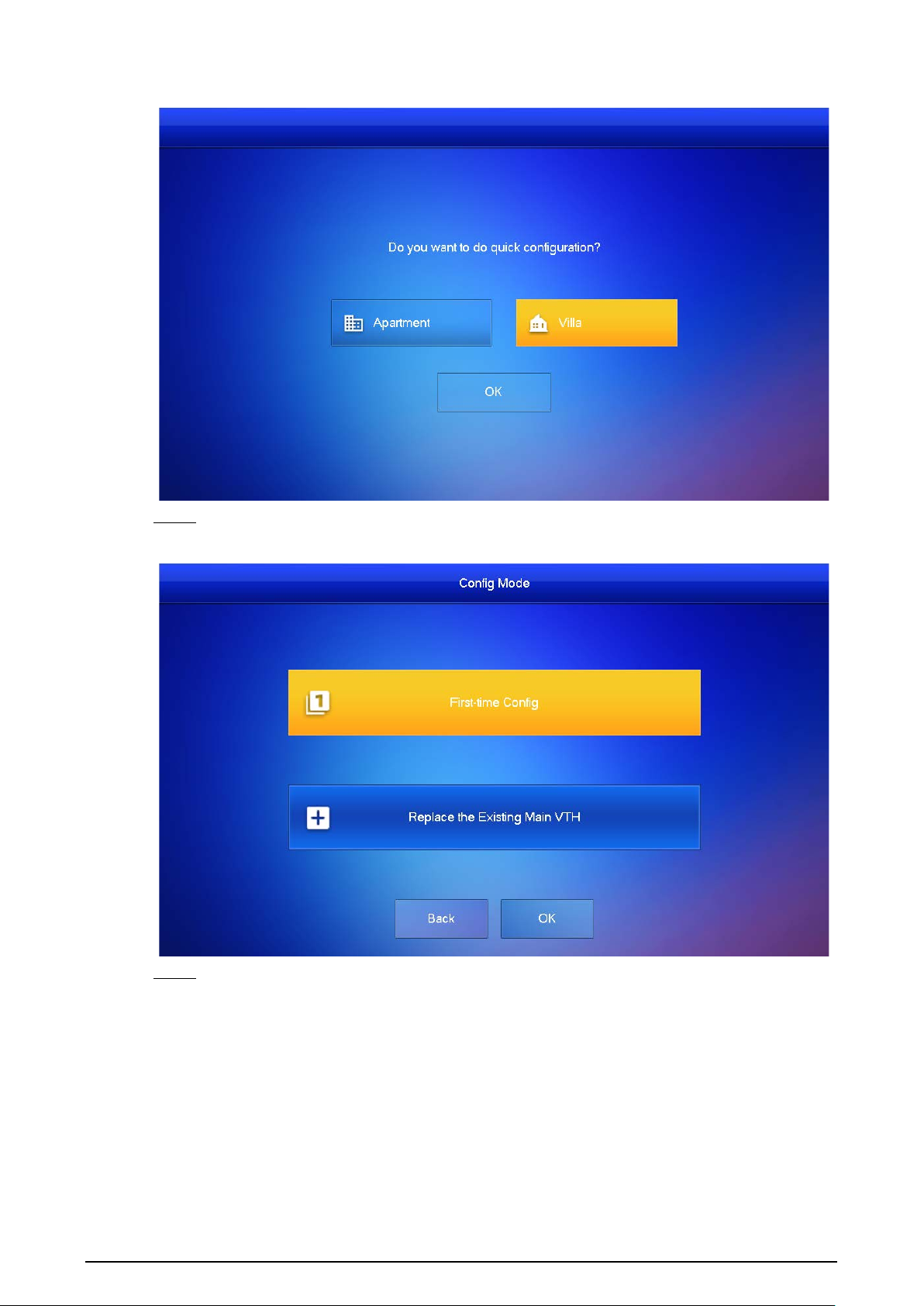
Step 3 Set the quick configuration type as
Villa
, and then tap
OK
.
13
Figure 3-2 Quick configuration
Step 4 Select
First-time Config
, and then tap
OK
.
Figure 3-3 Configuration mode
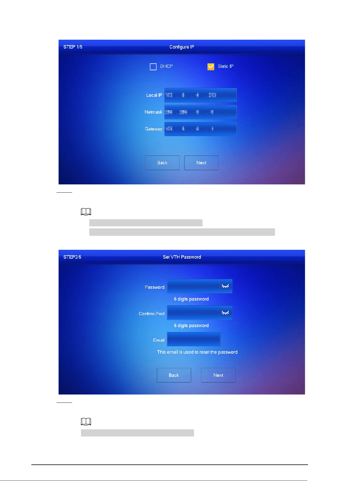
Step 5 Select
Static IP
, enter your planned VTH IP, net mask and gateway, and then tap
Next
.
14
Figure 3-4 Configure the network parameters
Step 6 On the
Set VTH Password
screen, enter and confirm the password, and enter the email
address, and then tap
Next
.
●
The password is used to enter project setting.
●
If you select
Apartment
in Step 2, initialization is completed with this step.
Figure 3-5 Set the password for the VTH
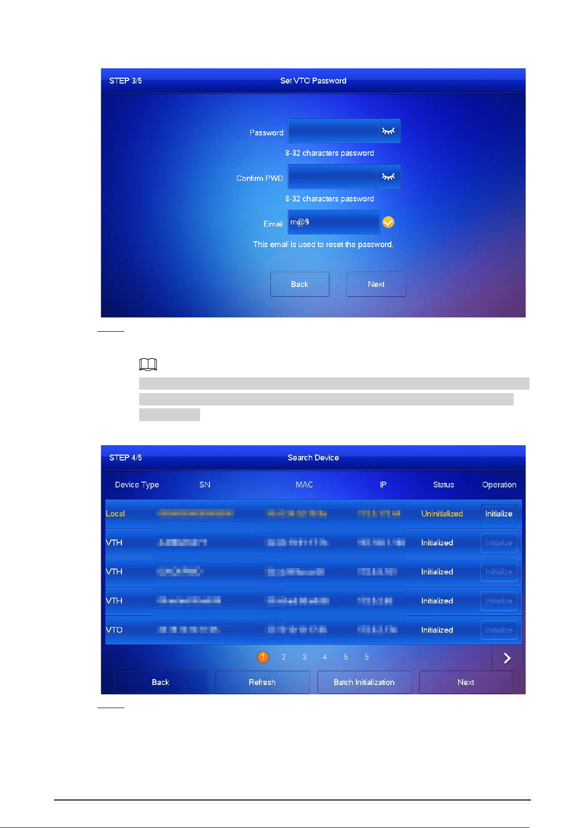
Step 7 On the
Set VTO Password
screen, enter the password of the VTO, confirm it, and then tap
Next
.
The password is used to enter project setting.
15
Figure 3-6 Set the password for the VTO
Step 8 Tap
Initialize
to complete the initialization of the VTO and the main VTH, and then tap
Next
.
You need to make sure that the IP addresses of the VTH and VTO are on the same network
segment. Otherwise, the VTH will not be able to obtain information from the VTO after
configuration.
Figure 3-7 Initialize the devices
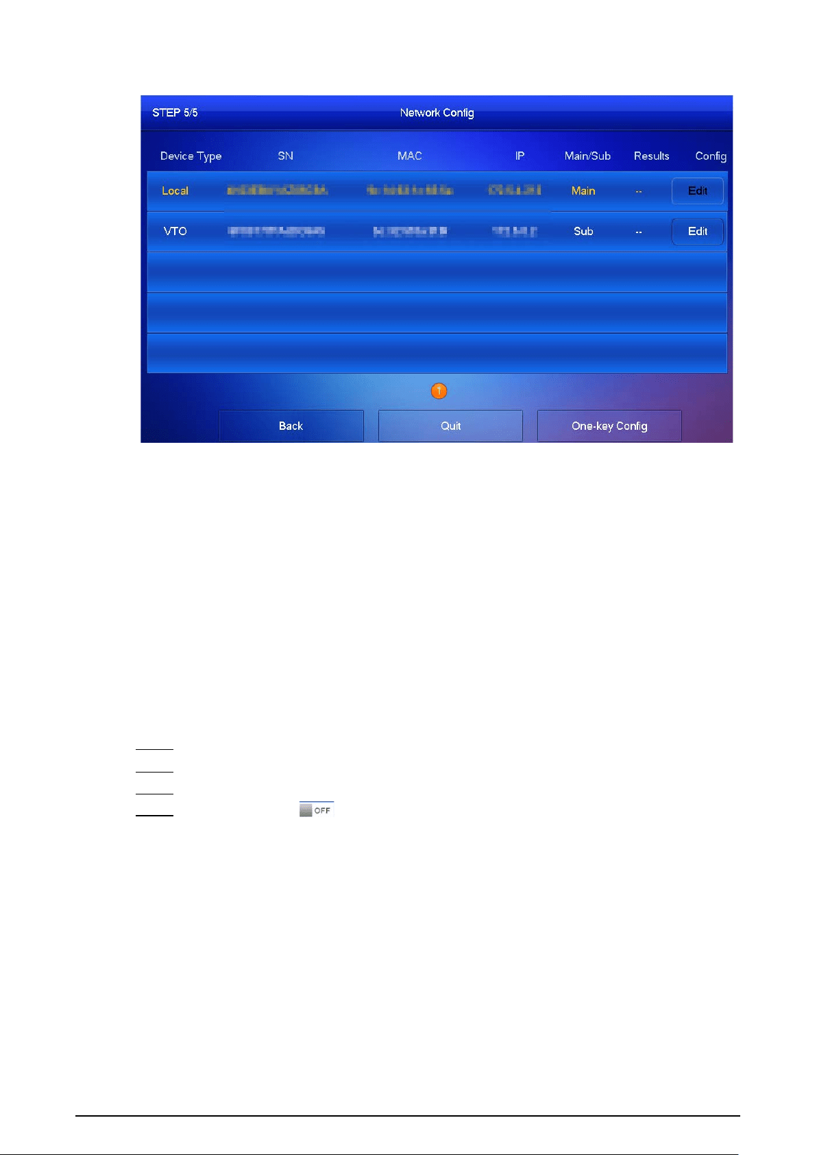
Step 9 Tap
One-key Config
to finish the configuration of the VTO and VTH, as well as the SIP
server.
The status bar will inform you whether your configuration was successful.
16
Figure 3-8 Finish the configuration
3.2 Manual Configuration
You can manually configure the parameters you want to modify.
3.2.1 Configuring Network Parameters
You can choose to connect the VTH to the network either through WLAN or LAN.
3.2.1.1 LAN
Procedure
Step 1 Select
Setting
>
Project Setting
, and enter the password that you set for the VTH.
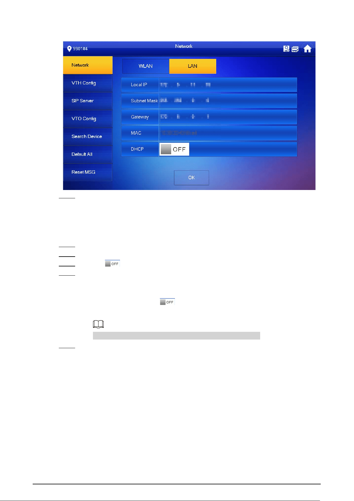
Step 2 Tap
Network
>
LAN
.
Step 3 Enter the local IP subnet mask and gateway that you planned for the VTH.
Step 4 You can also tap to enable the DHCP function to obtain IP information
automatically.
17
Figure 3-9 LAN
Step 5 Tap
OK
.
3.2.1.2 WLAN
Procedure
Step 1 Select
Setting
>
Project Setting
, and enter the password that you set for the VTH.
Step 2 Tap
Network
>
WLAN
.
Step 3 Enable to see all the usable networks.
Step 4 Before connecting to a Wi-Fi network, do either of the following first.
●
Tap
WireLessIP
, enter the local IP, subnet mask and gateway that you planned for the
VTH, and then tap
OK
.
●
Tap
WireLessIP
, and tap to enable the DHCP function to obtain IP information
automatically.
To enable the DHCP function, use a router with a DHCP function.
Step 5 On the
WLAN
screen, tap the Wi-Fi name, and then enter the password to connect to the
network.

18
Figure 3-10 WLAN
3.2.2 Configuring the SIP Server
Procedure
Step 1 Select
Setting
>
Project Setting
, and enter the password that you set for the VTH.
Step 2 Tap
SIP Server.
Figure 3-11 SIP server
Step 3 Configure the SIP server parameters.
Step 4 Set
Enable Status
to .
Step 5 Tap
OK
.
19
Table 3-1 SIP server
Parameter Description
Server IP
●
When the platform is set as the SIP server, the server IP is the IP
address of the platform.
●
When the VTO is set as the SIP server, the server IP is the IP address
of the VTO.
Network Port
●
When the platform is set as the SIP server, the network port is
5080.
●
When the VTO is set as the SIP server, the network port is 5060.
Username
Do not change it from the default.
Register Pwd
Domain
Registration domain of the SIP server. It can be null.
When the VTO is set as the SIP server, the registration domain of the
SIP server is VDP.
Username
Username and password to log in to the SIP server.
Login Pwd
3.2.3 Configuring the VTH
Procedure
Step 1 Select
Setting
>
Project Setting
, and enter the password that you set for the VTH.
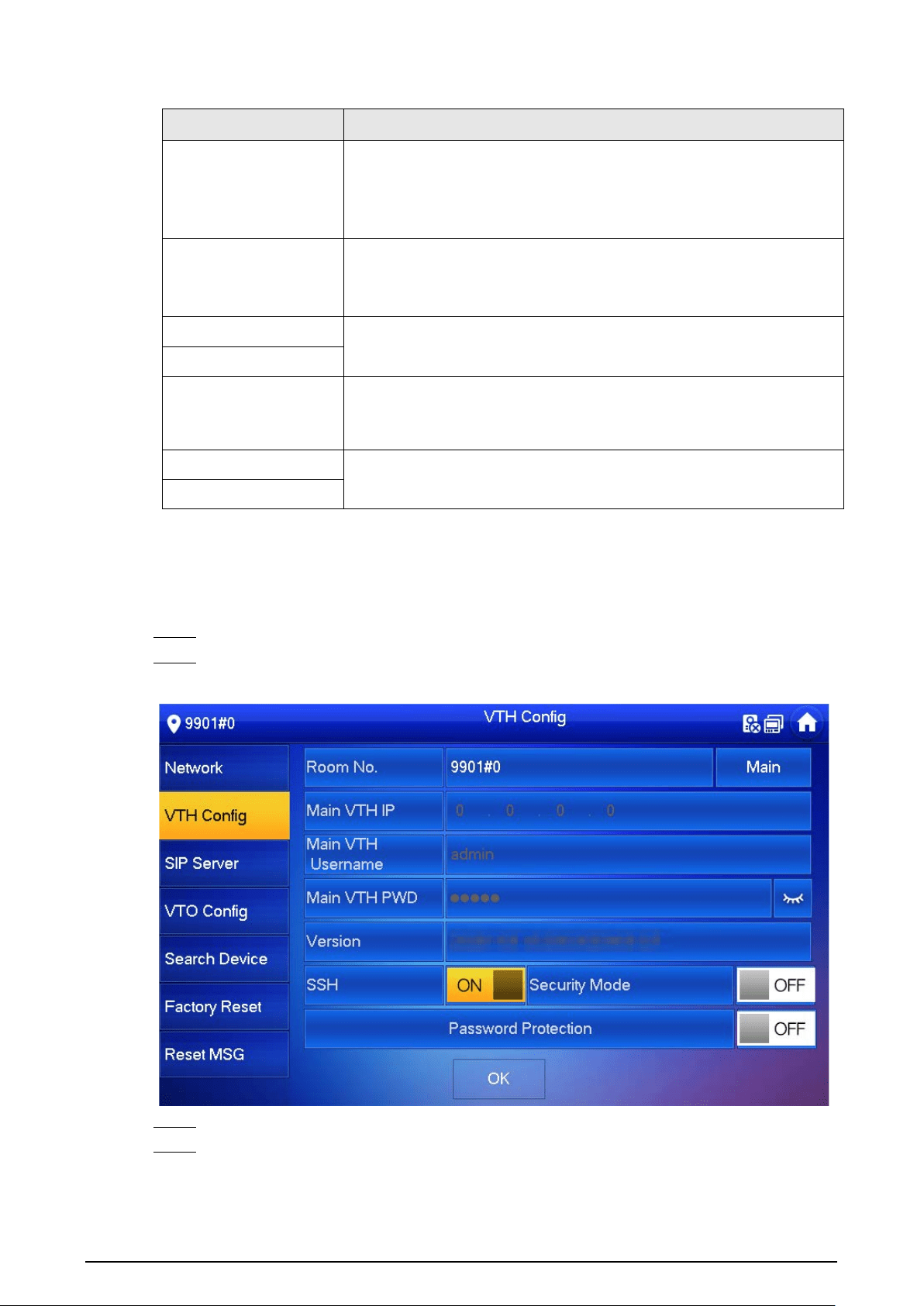
Step 2 Tap
VTH Config.
Figure 3-12 VTH Configuration
Step 3 Enter the room number (such as 9901 or 101#0).
Step 4 Configure parameters of the VTH. If there is an extension VTH, the room number must end
with #0. Otherwise, it will fail to connect to the VTO.
●
As a main VTH.
20
Enter the room number (such as 9901 or 101#0) and other information, and then tap
OK.
Room number must be the same with
VTH Short No.
, which is configured when
adding the VTHs on the webpage of the VTO. Otherwise, it will fail to connect to the
VTO.
When there are extension VTHs, room numbers must end with #0. Otherwise, it will fail
to connect to the VTO.
●
As an extension VTH.
1. Switch
Main
to
Extension
.
2. Enter the room number (such as 101#1), the IP address of the main VTH and other
information, and then tap
OK
.
Main VTH Username
and
Main VTH PWD
are the username and password of the
main VTH. Default user name is admin, and the password is the one you set during
initialization.
Step 5 Turn on the following functions as needed.
●
SSH
: The debugging terminal will connect to the VTH remotely through SSH protocol.
●
Security Mode
: Log in to the VTO in a secured way.
●
Password Protection
: Encrypt the password before sending out.
It is recommended to turn off SSH, and turn on security mode and password protection.
Otherwise, the device might be exposed to security risks and data leakage.
Step 6 Tap
OK
.
3.2.4 Configuring the VTO
Add VTOs and fence stations to bind them with the VTH.
Procedure
Step 1 Select
Setting
>
Project Setting
, and then enter the password that you set for the VTH.
Step 2 Tap
VTO Config.
21
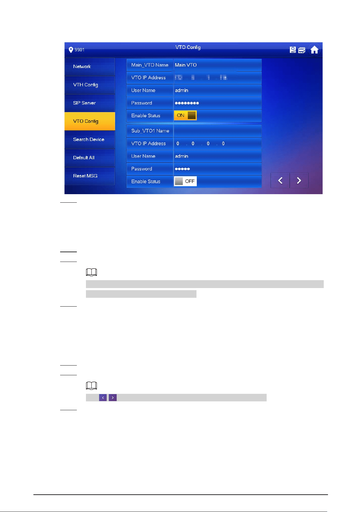
Figure 3-13 VTO configuration
Step 3 Add VTO.
3.2.4.1 Adding the Main VTO
Procedure
Step 1 Enter the main VTO name, VTO IP address, username and password.
Step 2 Turn on
Enable Status
.
User Name
and
Password
must be consistent with the username and password that are
used to log in to the webpage of the VTO.
Step 3 Check whether the configuration is successful by checking the status bar at the top right
corner.
3.2.4.2 Adding the Sub VTO
Procedure
Step 1 Enter the sub VTO name, sub VTO IP address, username, and password.
Step 2 Turn on
Enable Status
.
Tap / to turn pages and add more sub VTOs or fence stations.
Step 3 Check whether the configuration was successful by checking the status bar at the top right
corner.
22
4 Commissioning
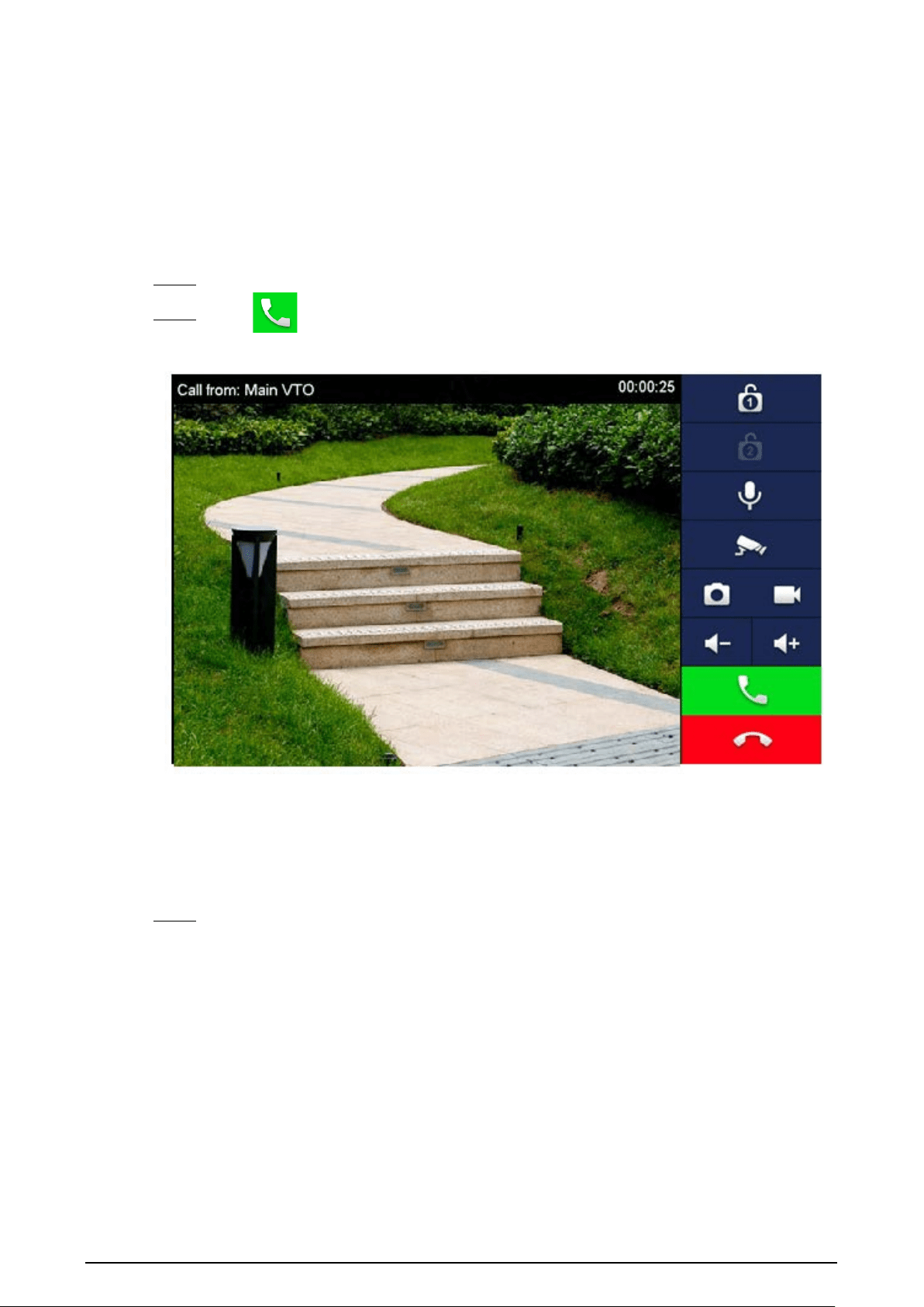
4.1 Using the VTO to Call the VTH
Procedure
Step 1 Dial a room number on the VTO.
Step 2 Tap on the VTH to answer the call.
Figure 4-1 Call screen
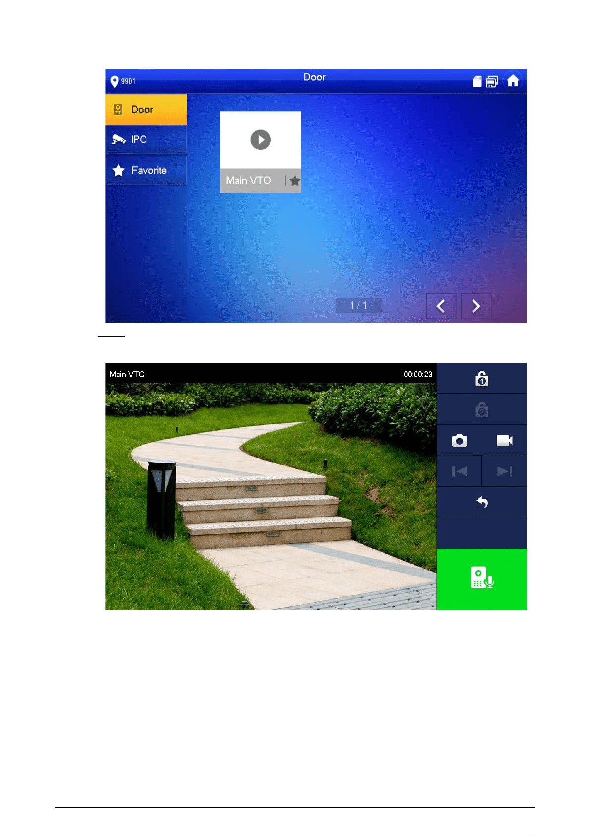
4.2 Using the VTH to Monitor the VTO
Procedure
Step 1 On the home screen of the VTH, select
Monitor
>
Door
.
23
Figure 4-2 Door
Step 2 Select a VTO to view the VTO video.
Figure 4-3 Monitoring video

24
Appendix 1 Cybersecurity Recommendations
Mandatory actions to be taken for basic device network security:
1.
Use Strong Passwords
Please refer to the following suggestions to set passwords:
●
The length should not be less than 8 characters.
●
Include at least two types of characters; character types include upper and lower case letters,
numbers and symbols.
●
Do not contain the account name or the account name in reverse order.
●
Do not use continuous characters, such as 123, abc, etc.
●
Do not use overlapped characters, such as 111, aaa, etc.
2.
Update Firmware and Client Software in Time
●
According to the standard procedure in Tech-industry, we recommend to keep your device
(such as NVR, DVR, IP camera, etc.) firmware up-to-date to ensure the system is equipped with
the latest security patches and fixes. When the device is connected to the public network, it is
recommended to enable the“auto-check for updates” function to obtain timely information
of firmware updates released by the manufacturer.
●
We suggest that you download and use the latest version of client software.
"Nice to have" recommendations to improve your device network security:
1.
Physical Protection
We suggest that you perform physical protection to device, especially storage devices. For
example, place the device in a special computer room and cabinet, and implement well-done
access control permission and key management to prevent unauthorized personnel from
carrying out physical contacts such as damaging hardware, unauthorized connection of
removable device (such as USB flash disk, serial port), etc.
2.
Change Passwords Regularly
We suggest that you change passwords regularly to reduce the risk of being guessed or cracked.
3.
Set and Update Passwords Reset Information Timely
The device supports password reset function. Please set up related information for password
reset in time, including the end user’s mailbox and password protection questions. If the
information changes, please modify it in time. When setting password protection questions, it is
suggested not to use those that can be easily guessed.
4.
Enable Account Lock
The account lock feature is enabled by default, and we recommend you to keep it on to
guarantee the account security. If an attacker attempts to log in with the wrong password several
times, the corresponding account and the source IP address will be locked.
5.
Change Default HTTP and Other Service Ports
We suggest you to change default HTTP and other service ports into any set of numbers between
1024–65535, reducing the risk of outsiders being able to guess which ports you are using.
6.
Enable HTTPS
We suggest you to enable HTTPS, so that you visit Web service through a secure communication
channel.
7.
MAC Address Binding
We recommend you to bind the IP and MAC address of the gateway to the device, thus reducing

25
the risk of ARP spoofing.
8.
Assign Accounts and Privileges Reasonably
According to business and management requirements, reasonably add users and assign a
minimum set of permissions to them.
9.
Disable Unnecessary Services and Choose Secure Modes
If not needed, it is recommended to turn off some services such as SNMP, SMTP, UPnP, etc., to
reduce risks.
If necessary, it is highly recommended that you use safe modes, including but not limited to the
following services:
●
SNMP: Choose SNMP v3, and set up strong encryption passwords and authentication
passwords.
●
SMTP: Choose TLS to access mailbox server.
●
FTP: Choose SFTP, and set up strong passwords.
●
AP hotspot: Choose WPA2-PSK encryption mode, and set up strong passwords.
10.
Audio and Video Encrypted Transmission
If your audio and video data contents are very important or sensitive, we recommend that you
use encrypted transmission function, to reduce the risk of audio and video data being stolen
during transmission.
Reminder: encrypted transmission will cause some loss in transmission efficiency.
11.
Secure Auditing
●
Check online users: we suggest that you check online users regularly to see if the device is
logged in without authorization.
●
Check device log: By viewing the logs, you can know the IP addresses that were used to log in
to your devices and their key operations.
12.
Network Log
Due to the limited storage capacity of the device, the stored log is limited. If you need to save the
log for a long time, it is recommended that you enable the network log function to ensure that
the critical logs are synchronized to the network log server for tracing.
13.
Construct a Safe Network Environment
In order to better ensure the safety of device and reduce potential cyber risks, we recommend:
●
Disable the port mapping function of the router to avoid direct access to the intranet devices
from external network.
●
The network should be partitioned and isolated according to the actual network needs. If
there are no communication requirements between two sub networks, it is suggested to use
VLAN, network GAP and other technologies to partition the network, so as to achieve the
network isolation effect.
●
Establish the 802.1x access authentication system to reduce the risk of unauthorized access to
private networks.
●
Enable IP/MAC address filtering function to limit the range of hosts allowed to access the
device.