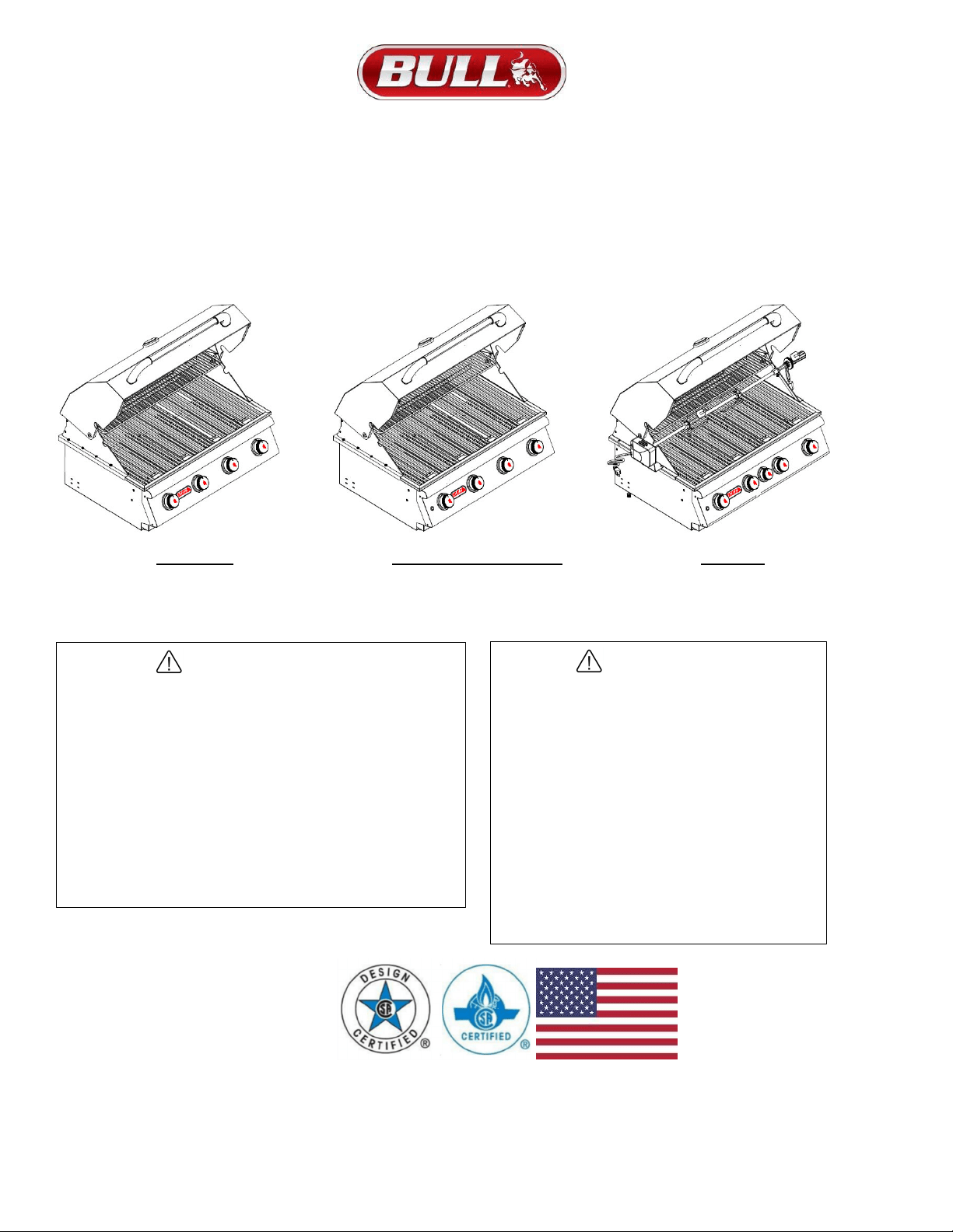
30 INCH GRILL HEADS
ASSEMBLY & OPERATING INSTRUCTIONS
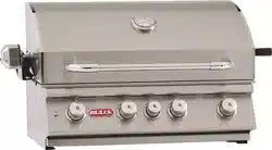
OUTLAW
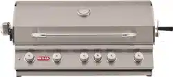
LONESTAR SELECT
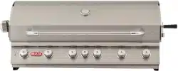
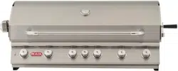
ANGUS
MODEL #26038 (L.P.) MODEL #87048 (L.P.) MODEL #47628 (L.P.)
MODEL #26039 (N.G.) MODEL #87049 (N.G.) MODEL #47629 (N.G.)
DANGER
If you smell gas:
•
Shut off gas to the appliance.
•
Extinguish any open flame.
•
Open lid.
•
If odor continues, keep away from
the appliance and immediately call
your gas supplier or your
fire department.
WARNING
•
Do not store or use gasoline
or other flammable liquids
or vapors in the vicinity of
this or any other appliance.
•
An LP cylinder not
connected for use shall
not be stored in the
vicinity of this or any
other appliance.
USA EDITION
2
TABLE OF CONTENTS PAGE #
SAFETY INSTRUCTIONS2
GRILL OPERATIONAL SAFETY............................................................................................................................................................................... 3
CHECKING FOR GAS LEAKS .................................................................................................................................................................................. 4
LIQUID PROPANE GAS SAFETY ............................................................................................................................................................................ 5
LIQUID PROPANE TO NATURAL GAS CONVERSION……………………………………………………………………………………………………..6
NATURAL GAS SAFETY…………………………………………………………………………………………………………………………………………6
INSTALLATION INSTRUCTIONS
GRILL LOCATION .................................................................................................................................................................................................... .7
GRILL VENTILATION ................................................................................................................................................................................................ 7
GRILL VENTILATION WHEN INSTALLED INTO ISLANDS FOR ENCLOSURES………………………………………………………………………..8
LP GAS CONNECTION SPECIFICATIONS FOR ISLANDS AND ENCLOSURE .................................................................................................... 9
LP GAS TANK RETENTION.................................................................................................................................................................................... 10
NATURAL GAS CONNECTION SPECIFICATIONS FOR ISLANDS AND ENCLOSURE ...................................................................................... 11
GRILL LIGHTING SYSTEM TRANSFORMER INSTALLATION ............................................................................................................................. 12
GRILL OPERATION AND COOKING GUIDELINES
FIRST USE AND LIGHTING INSTRUCTIONS AND SAFETY……………………………………………………………………………………………13-15
COOKING COMPONENT INSTALLATION AND BASIC COOKING METHODS AND SAFETY……………………………………………………….16
ROTISSERIE SYSTEM OPERATION ………………………………………………………………………………………………………………………17
GRILL BURNER REMOVAL INSPECTION / CLEANING BURNERS AND GAS VALVE ORIFICES BURNER CLEANING
BURNER REMOVAL INSTRUCTIONS.………………………………………………………………………………………………………………………18
BURNER INSPECTION AND CLEANING .............................................................................................................................................................. 19
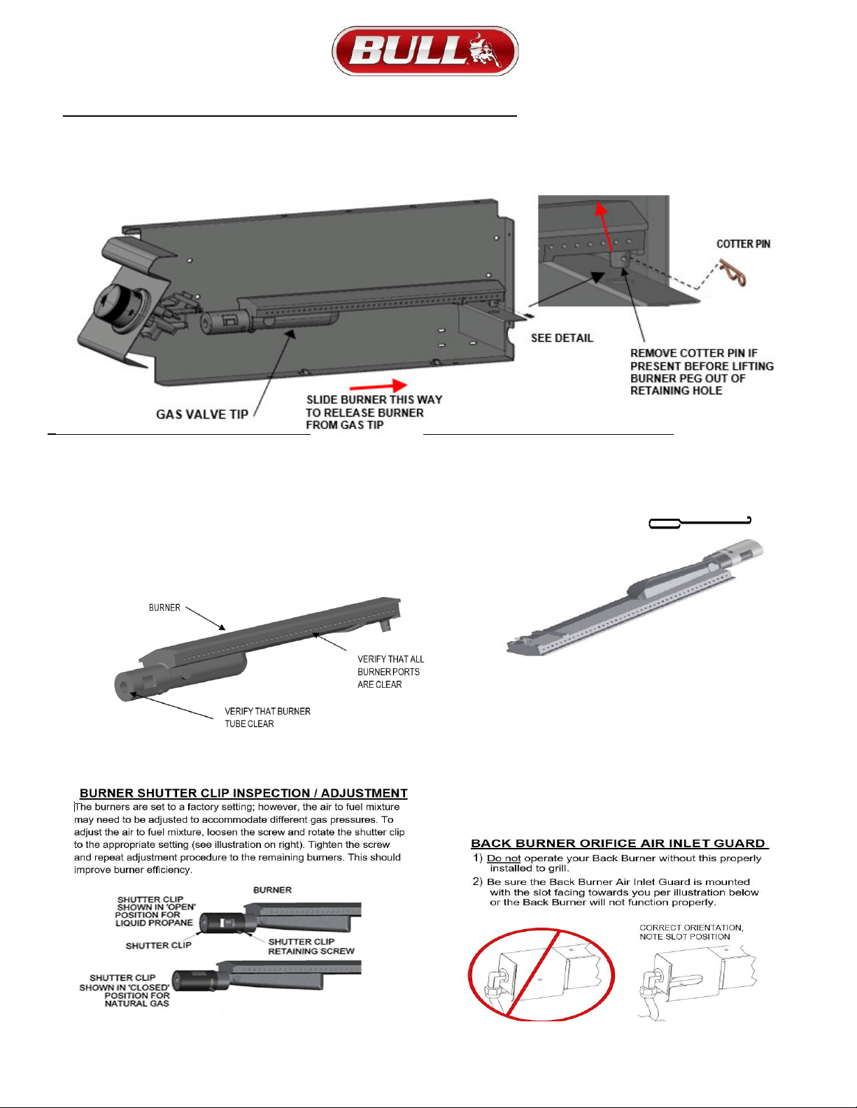
BURNER SHUTTER CLIP INSPECTION AND ADJUSTMENT……………………………………………………………………………………………19
BACK BURNER ORIFICE AIR INLET GUARD INSPECTION AND INSTALLATION……………………………………………………………………19
INSTALLING BURNERS BACK INTO GRILL ......................................................................................................................................................... 20
IGNITOR / ELECTRODE CHECK……………………………………………………………………………………………………………………………..20
GRILL LIGHTING SYSTEM
LIGHT BULB REPLACEMENT ................................................................................................................................................................................ 21
LIGHT SYSTEM CONNECTION DIAGRAM ........................................................................................................................................................... 21
ANNUAL CLEANING & MAINTENANCE ......................................................................................................................................................... 22-23
TROUBLESHOOTING………………………………................................................................................................................................................24
IF GRILL FAILS TO OPERATE PROPERLY ………………………………………………………………………………………………………………..24
YELLOW FLAME AND FLASH BACK ................................................................................................................................................................... 24
HOW TO REGISTER YOUR GRILL, SERIAL NO. LOCATION, REPLACEMENT PART ORDERING… .............................................................. 25
OUTLAW REPLACEMENT PARTS LIST AND REFERENCE DRAWING ...................................................................................................... 26-27
LONESTAR SELECT REPLACEMENT PARTS LIST AND REFERENCE DRAWING ............................................................................ ……28-29
ANGUS REPLACEMENT PARTS LIST AND REFERENCE DRAWING ......................................................................................................... 30-31
ROTISSERIE PARTS LIST AND EXPLODED ILLUSTRATION ............................................................................................................................ 32
LIMITED WARRANTY POLICY ......................................................................................................................................................................... 33-35
READ THIS ENTIRE MANUAL CAREFULLY AND RETAIN FOR FUTURE REFERENCE
.
BE SURE YOUR GRILL IS PROPERLY INSTALLED, ASSEMBLED AND CARED FOR. FAILURE TO FOLLOW THESE INSTRUCTIONS MAY RESULT IN SERIOUS BODILY
INJURY AND/OR PROPERTY DAMAGE. IF YOU HAVE QUESTIONS CONCERNING ASSEMBLY OR OPERATION, CONSULT YOUR DEALER, GAS APPLIANCE SERVICE
REPRESENTATIVE OR YOUR GAS COMPANY.
-
NOTE TO INSTALLER: LEAVE THESE INSTRUCTIONS WITH THE CONSUMER AFTER INSTALLATION.
-
NOTE TO THE CONSUMER: RETAIN THESE INSTRUCTIONS FOR FUTURE REFERENCE.
-
THIS OUTDOOR COOKING GAS APPLIANCE IS NOT INTENDED TO BE INSTALLED IN OR ON RECREATIONAL VEHICLES AND/OR BOATS.
*FOR WARRANTY PURPOSES, PLEASE RECORD YOUR MODEL NUMBER, SERIAL NUMBER, DATE OF PURCHASE ON THE REGISTRATION CARD ON PAGE 25
ALONG WITH ATTACHING A COPY OF YOUR RECEIPT OR INVOICE TO PAGE 25.
v.2022.06.28
WARNING: Fuels used in gas or oil-fired appliances and the
products of combustion of such fuels, contain chemicals known to
the State of California to cause cancer, birth defects and/or
reproductive harm. This warning is issued pursuant to California
Health & Safety Code Sec. 25249.6
.
3
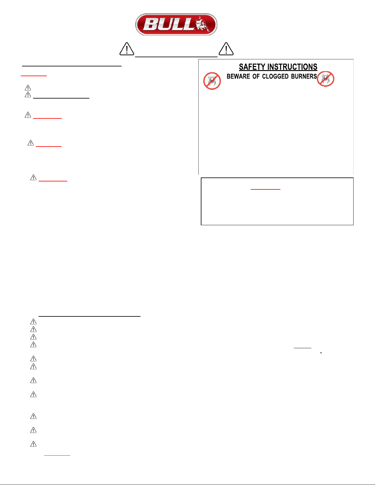
SAFETY INSTRUCTIONS
GRILL OPERATIONAL SAFETY
WARNING!
FOR YOUR SAFETY, READ THE GUIDELINES BELOW
FOR ASSEMBLY AND OPERATION OF YOUR GRILL.
YOUR GAS GRILL IS ONLY FOR OUTDOOR USE.
PROTECT CHILDREN:
DO NOT ALLOW CHILDREN TO OPERATE
GRILL. KEEP THEM AWAY FROM THE GRILL DURING USE, AND UNTIL
THE GRILL HAS COOLED COMPLETELY.
WARNING:
DO NOT USE YOUR GAS GRILL UNDER EXTENDED
AWNINGS, GARAGES, PORCHES, BREEZEWAYS, SHEDS OR OTHER
ENCLOSED AREAS. FAILURE TO DO SO COULD RESULT IN A FIRE OR
PERSONAL INJURY.
DANGER:
DO NOT PUT GRILL IN STORAGE OR TRAVEL
MODE IMMEDIATELY AFTER USE. ALLOW GRILL TO COOL
TO TOUCH BEFORE MOVING OR STORAGE. FAILURE TO DO
SO COULD RESULT IN FIRE RESULTING IN PROPERTY
DAMAGE, PERSONAL INJURY OR DEATH.
WARNING: The outdoor cooking gas appliance, when
installed, must be electrically grounded in accordance
with local codes or, in the absence of local codes, with the
National Electrical Code, ANSI/NFPA 70, or the Canadian
Electrical Code, Part I, CSA C22.1.
a)
To protect against electric shock, do not immerse cord or plugs
in water or other liquid.
b) Unplug from the outlet when not in use and before cleaning. Allow to cool before putting on or taking off parts.
c) Do not operate any outdoor cooking gas appliance that has malfunctioned or been damaged in any manner, such as a damaged
power cord or plug. Contact the manufacturer for repair.
d) Do not let the cord hang over the edge of a table or touch hot surfaces.
e) Do not use an outdoor cooking gas appliance for purposes other than intended
f) When connecting, first connect plug to the outdoor cooking gas appliance then plug appliance into the outlet
g) Use only a Ground Fault Interrupter (GFI) protected circuit with this outdoor cooking gas appliance.
h) Never remove the grounding plug or use with an adapter of 2 prongs.
i) Use only extension cords with a 3 prong grounding plug, rated for the power of the equipment, and approved for outdoor use with
a W-A marking.
ADDITIONAL SAFETY INSTRUCTIONS:
THIS GRILL IS NOT INTENDED FOR USE IN OR ON RECREATIONAL VEHICLES AND/OR BOATS.
DO NOT PLACE GRILL UNDER OR ON TOP OF AN SURFACE THAT WILL BURN
.
DO NOT ALLOW OBSTRUCTION OR RESTRICTION TO THE FLOW OF COMBUSTION AND VENTILATION AIR AROUND THE GRILL HOUSING.
GRILL CLEARANCE FROM THE BACK AND SIDE OF ANY COMBUSTIBLE SURFACE MUST BE AT LEAST 21 INCHES. DO NOT STORE
OR USE GASOLINE, OR OTHER LIQUIDS EMITTING FLAMMABLE VAPORS IN THE VICINITY OF GRILL OR ANY OTHER APPLIANCES.
DO NOT STORE EMPTY OR FULL SPARE LP GAS CYLINDERS AND/OR CHEMICALS UNDER OR NEAR GRILL OR ANY OTHER APPLIANCES.
KEEP THE FUEL HOSE AND ELECTRICAL CORDS AWAY FROM HOT SURFACES AND DRIPPING GREASE. CHECK AND CLEAN BURNER
VENTURI TUBES FOR INSECTS AND DEBRIS. A CLOGGED TUBE CAN LEAD TO A FIRE BENEATH THE GRILL.
KEEP THE VENT OPENINGS OF THE CYLINDER ENCLOSURE FREE AND CLEAR FROM DEBRIS.CLEAN OUTDOOR COOKING GAS
APPLIANCE WITH RECOMMENDED CLEANING AGENTS.
AVOID UNNECESSARY TWISTING OF THE HOSE. VISUALLY INSPECT THE HOSE PRIOR TO EACH USE FOR CUTS, CRACKS,
EXCESSIVE WEAR OR OTHER DAMAGE AND REPLACE IF NECESSARY. THE REPLACEMENT HOSE SHOULD BE THAT SPECIFIED BY
THE MANUFACTURER.
NEVER LIGHT GRILL WITH LID CLOSED OR BEFORE CHECKING TO ENSURE BURNER TUBES ARE FULLY SEATED OVER GAS
VALVE ORIFICES.
NEVER LEAN OVER COOKING SURFACE WHILE LIGHTING GRILL. USE BARBECUE TOOLS WITH WOOD HANDLES AND
GOOD QUALITY INSULATED OVEN MITTS WHEN OPERATING GRILL.
NEVER PLACE OBJECTS OR UTENSILS ON TOP OF GRILL LID.
WARNING: IF THESE GUIDELINES ARE NOT FOLLOWED, FIRE CAUSING SERIOUS INJURY OR DEATH MAY OCCUR.
DUE TO SPIDER WEBS
CAUTION: BURNERS MUST BE INSPECTED AND
CLEANED BEFORE FIRST USE.
Spiders and small insects occasionally spin webs or make
nests in the burners during warehousing, transit and/or after
long periods of non- use. These webs can lead to a gas flow
obstruction, which could result in a fire in and around the
burner venturi tubes. This type of fire is known as “FLASH-
BACK” and can cause serious damage to your grill and
create an unsafe operating condition for the user. Although
an obstructed burner tube is not the only cause of “FLASH
BACK” it is the most common cause, and frequent inspection
and cleaning of the burners is necessary.
WARNING
NEVER cover slots, holes or openings in the grill bottom or
cover an entire cooking grate with material such as
aluminium foil. Doing so blocks air flow through the oven
and may cause carbon monoxide poisoning.
Aluminium foil linings may trap heat causing a fire hazard.
4
GRILL OPERATIONAL SAFETY (CONTINUED)
WARNING! FOR YOUR SAFETY...
1) DO NOT store or use gasoline or other flammable vapors and liquids in the vicinity of this or any other
appliance.
2) DO NOT store empty or full spare gas cylinders and/or chemicals under or near this or any other appliance.
3) Keep the fuel hose away from hot surfaces. Protect the fuel hose from dripping grease. Avoid unnecessary
twisting of the hose. Visually inspect the hose prior to each use for cuts, cracks excessive wear or other
damage and replace if necessary.
4) NEVER test for gas leaks with a lighted match or open flame.
5) NEVER light grill with lid closed or before checking to ensure burner tubes are fully seated over gas valve
orifices.
6) NEVER lean over cooking surface while lighting grill. Use barbecue tools with wood handles and good
quality insulated oven mitts when operating grill.
7) Keep any electrical supply cord and the fuel supply hose away from any heated surfaces.
DANGER! IF YOU SMELL GAS...
1) Shutoff gas to the appliance at its source.
2) Extinguish any open flame.
3) Open grill lid to release any accumulation of fumes.
4) If gas odor persists, immediately contact your gas supplier or your fire department.
WARNING: IF THESE GUIDELINES ARE NOT FOLLOWED, FIRE CAUSING SERIOUS INJURY OR DEATH MAY OCCUR.
CHECKING FOR GAS LEAKS
NEVER TEST FOR GAS LEAKS WHILE THE GRILL IS LIT!
Prior to the first use and at the beginning of each new season (or, if using LP, whenever gas cylinder is changed), it is a must that you
check for gas leaks.
Follow these steps:
1) Make a soap solution by mixing 1 part liquid detergent and one part water.
2) Turn off heat control valves, and then turn on gas at source.
3) Apply the soap solution to all gas connections: bubbles will appear in the soap solution if connections are not properly sealed,
tighten or repair as necessary.
4) If you have a gas leak that you cannot repair, turn off the gas at the source, disconnect fuel line from the double side burner and
immediately call your dealer and gas supplier for professional assistance.
WHEN THE OUTDOOR COOKING GAS APPLIANCE IS NOT IN USE
WARNING: When the outdoor cooking gas appliance is not in use, the gas supply must be turned off at the supply cylinder. Storage
of an outdoor cooking gas appliance indoors is permissible only if the cylinder is disconnected and removed from the outdoor cooking
gas appliance.
1) Cylinder must be stored outdoors, out of reach of children and must not be stored in a building, garage or any other enclosed area.
2) Place dust cap on cylinder valve outlet whenever the cylinder is not in use. Only install the type of dust cap on
the cylinder valve outlet that is provided with the cylinder valve. Other types of caps or plugs may result in leakage of propane.
3) Do not store a spare LP gas cylinder under or near this appliance.
4) Never fill the cylinder beyond 80 percent full.
5) If the information in 1) and Clause 2) is not followed exactly, a fire causing death or serious injury may occur.
5
LIQUID PROPANE (LP) SAFETY GUIDELINES
Your Propane gas grill is designed to operate on propane gas ONLY, at a pressure regulated at 11” water column (W.C.)
when equipped with the correct propane orifices on the valves and a propane regulator on the supply line regulated at the
residential meter. Your propane gas grill is designed to be used with a standard 20 lb. gas cylinder with size of 46cm
(Height) / 18.1in * 32cm (Width) / 12.5in. In the United States, the gas cylinder must be constructed and marked in
accordance with specifications of the US Department of Transportation for Propane Gas Cylinders.
1) ALWAYS KEEP LP GAS CYLINDER SECURELY FASTENED IN AN UPRIGHT POSITION.
2) NEVER CONNECT AN UNREGULATED LP GAS CYLINDER TO THE GRILL.
3) DO NOT SUBJECT LP GAS CYLINDERS TO EXCESSIVE HEAT.
4) DO NOT STORE SPARE LP GAS CYLINDERS UNDER OR NEAR THIS APPLIANCE.
5) DO NOT FILL LP GAS CYLINDER BEYOND 80% FULL.
IF WARNING NOTICES 1 AND 2 ARE NOT FOLLOWED, A FIRE CAUSING SERIOUS INJURY OR DEATH MAY OCCUR
6) CAUTION: CHANGING THE GAS TANKS MUST BE DONE AWAY FROM ANY SOURCE OF IGNITION.
7) LP GAS TANK MUST BE MARKED IN ACCORDANCE WITH THE SPECIFICATIONS FOR LP GAS CYLINDERS, SPHERES AND
TUBES FOR TRANSPORTATION OF DANGEROUS GOODS AND COMMISSION, CAN/CSA- B339, AS APPLICABLE
8) LP GAS TANK CONNECTION DEVICE IS COMPATIBLE WITH OUTDOOR COOKING APPLIANCES.
9) LP GAS TANK HAS APPROPRIATE VAPOR WITHDRAWAL.
10) LP GAS TANK MUST HAVE A LISTED OVERFILLING PREVENTION DEVICE.
11) LP GAS TANK MUST INCLUDE A COLLAR TO PROTECT THE CYLINDER VALVE.
12) LP GAS TANK USES A TYPE 1 TANK VALVE THAT IS FIRMLY SECURED IN AN UPRIGHT POSITION.
13) DO NOT USE AN LP CYLINDER THAT IS DAMAGED.
14) VISUALLY INSPECT THE LP HOSE PRIOR TO EACH USE FOR CUTS, CRACKS, EXCESSIVE WEAR OR DAMAGE. IF FOUND
ASSEMBLY SHOULD BE REPLACED, USE ONLY THE BULL PART NUMBERS SHOWN IN THE PARTS LIST SUPPLIED WITH THIS
UNIT. THE REPLACEMENT HOSE ASSEMBLY SHALL BE THAT SPECIFIED BY THE MANUFACTURER.
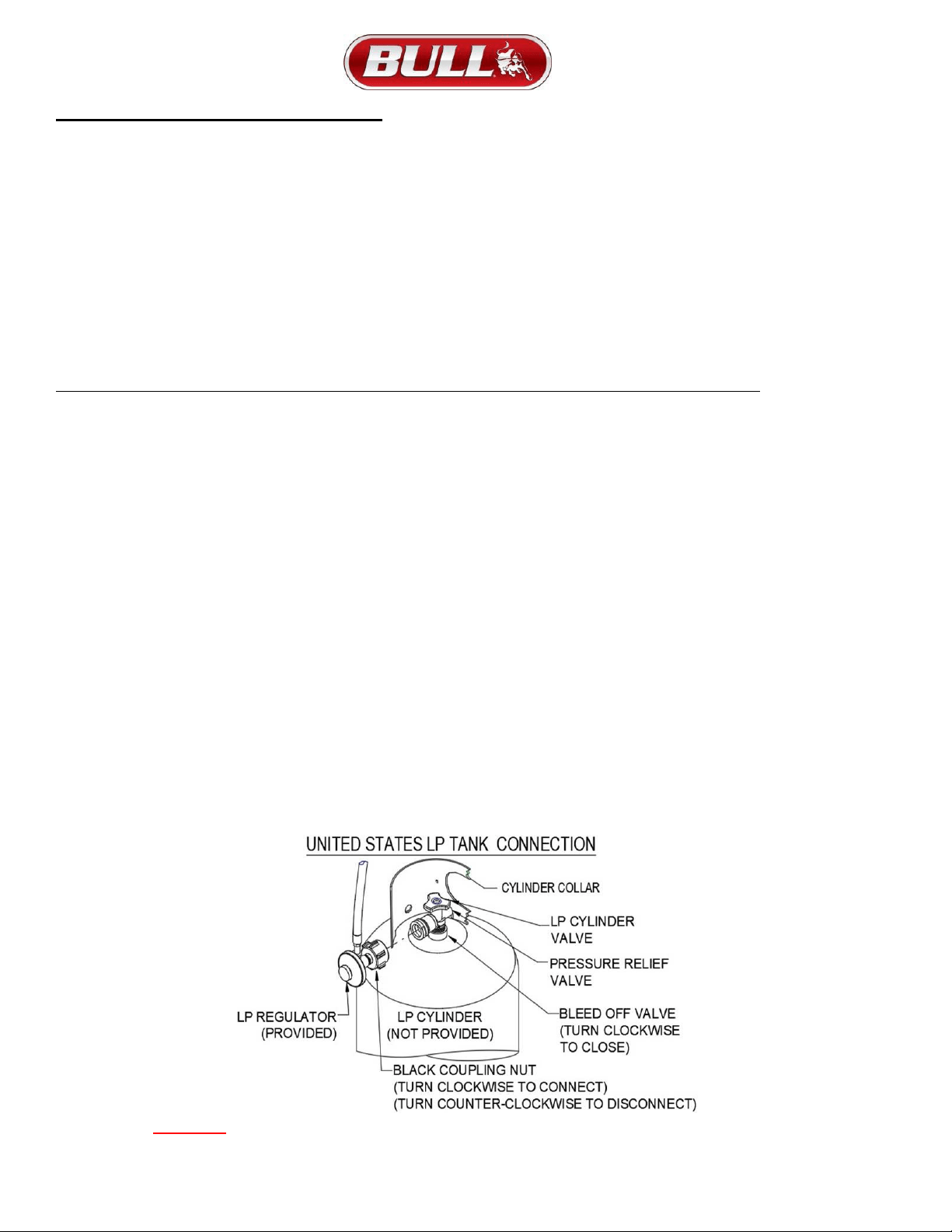
15)
LP GAS PRESSURE REGULATOR AND 31” INCH HOSE ASSEMBLY (BULL PART # 16589) ARE SUPPLIED AND
MUST BE USED WITHOUT ALTERATION AND SHOULD ONLY BE USED ON YOUR STALLION GRILL.
16)
TO CONNECT THE BLACK COUPLING, TURN NUT OF THE HOSE AND REGULATOR ASSEMBLY IN A CLOCKWISE
DIRECTION (SEE ILLUSTRATION BELOW) UNTIL IT IS COMPLETELY THREADED ONTO THE CYLINDER VALVE BEFORE
TURNING GAS SUPPLY ON. TO REMOVE TURN THE BLACK COUPLING NUT OF THE HOSE AND REGULATOR ASSEMBLY IN
A COUNTER- CLOCKWISE DIRECTION.
WARNING: If these guidelines are not followed, fire causing serious injury or death may occur.

6
LIQUID PROPANE GAS TO NATURAL GAS CONVERSION
Gas valves are pre-set at the Bull factory to operate on LP Gas or Natural Gas. If you wish to convert to a different gas type, other
than LP or NG, be sure to contact your grill dealer, licensed plumber or authorized service center for further details. Conversion
kits are not sold to the general public and require a professional to perform service. Failure to properly convert a unit can cause
serious injury to yourself and/or others, irreparable damage to your grill and void of warranty.
WARNING: IF THESE GUIDELINES ARE NOT FOLLOWED, FIRE CAUSING SERIOUS INJURY OR DEATH MAY OCCUR
.
NATURAL GAS (NG) SAFETY GUIDELINES
Your Natural Gas (G20) grill is designed to use NATURAL GAS ONLY. The grill operates at a pressure of 4” water column (wc)
or 10 mbar set at the natural gas regulator attached at the back of the grill. Prior to installing gas supply lines, check with your
local gas utility or municipality regarding local gas pressure and for building code requirements and instructions or consult a
licensed and knowledgeable installer.
NATURAL GAS PLUMBING TO CONNECTION SOURCE GUIDELINES
Refer to the following instructions and illustrations for typical gas supply connections.
We strongly suggest having your gas plumbing and connection to your grill be completed by a professional.
IMPORTANT: Before connecting grill to gas source, make sure BBQ Grill control knobs are in “OFF” position.
Be sure to follow instructions for connecting an appliance to a fixed fuel piping system specifying the use of a rigid pipe, semi-rigid tubing,
and/or a connector that complies with the Standard for Connectors for Outdoor Gas Appliances and Manufactured Homes, ANSI Z21.75
* CSA 6.27.
1)
Install an “ON-OFF” shutoff valve for OUTDOOR gas supply source after gas line piping exits outside wall, or before gas piping
enters ground.
2)
Install an “ON-OFF” shutoff valve for INDOOR gas supply source to the branch fuel line in an accessible location near the supply
line.
3)
Do not use Teflon ® tape or pipe sealant on any flare ends because you will not obtain a leak-free seal.
4)
Use only Pipe sealing compound or pipe thread tape of the type of resistant to the action of natural gas to at least the first three
threads of all male pipe threads when making the connection.
5)
Disconnect your gas grill from fuel source when the gas supply is being tested at high pressures. This appliance and its individual
shutoff valve must be disconnected from the gas supply piping system during any pressure testing of that system at pressures more
than 1/2 psig or 37 mbar.
6)
The outdoor cooking gas appliance and its individual shut-off valve must be disconnected from the gas supply piping system
during any pressure testing of that system at test pressures more than 0.5 psi (3.5 kPa).
7)
The outdoor cooking gas appliance must be isolated from the gas supply
piping system by closing its individual manual shut-off valve during any
pressure testing of the gas supply piping system at test pressures equal to or
less than 1/2 psi (3.5 kPa).
8)
Turn off your gas grill when the gas supply is being tested at low
pressures. This appliance must be isolated from the gas supply
piping system by closing its individual valve.
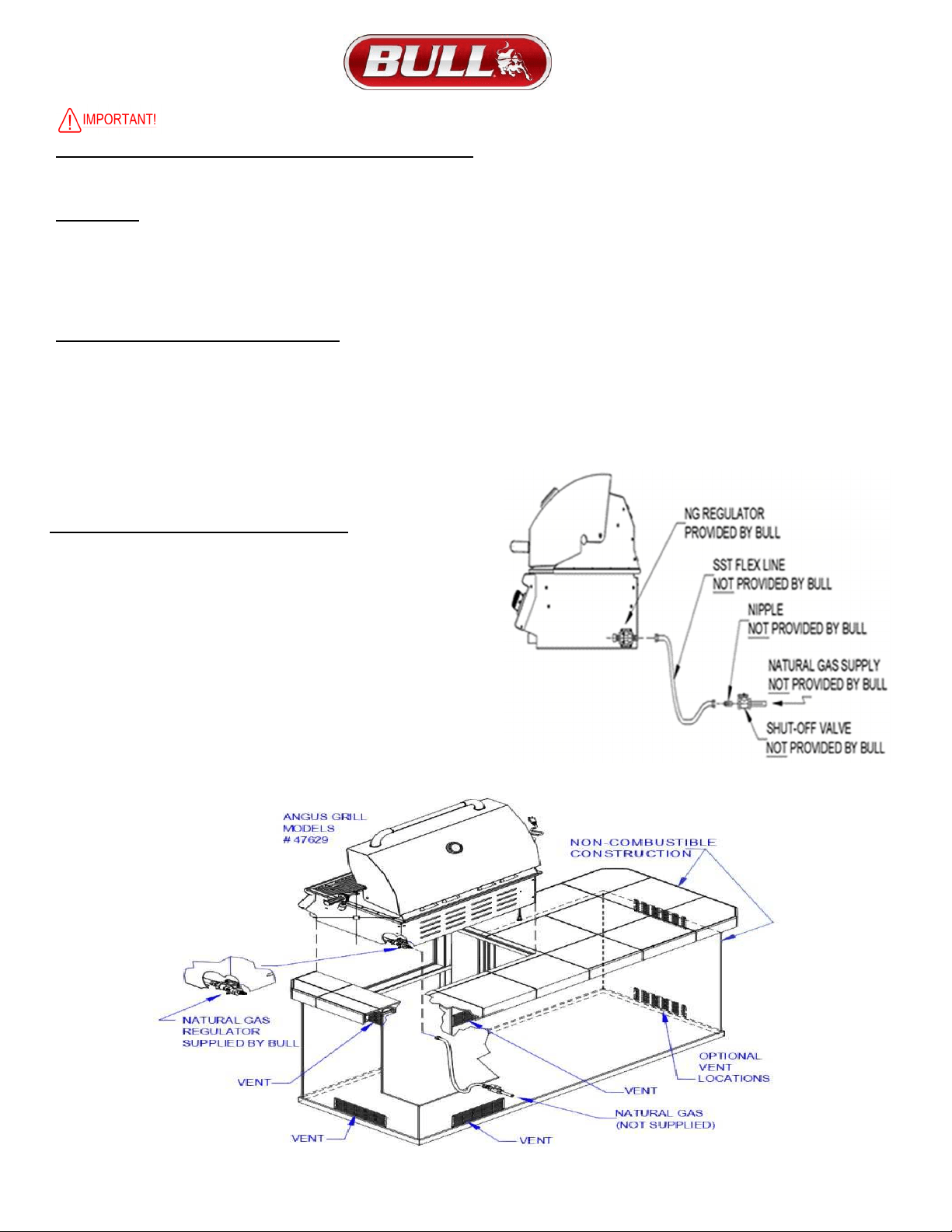
NATURAL GAS CONNECTION TO GRILL
IMPORTANT:
Bull Outdoor Products does not recommend the use of any quick
connect fittings or lines to the unit. Use of these types of fittings or lines could
cause low gas flow and greatly reduce the performance of the unit
.
1)
Do not use Teflon ® tape or pipe sealant on any flare ends because you
will not obtain a leak-free seal.
2)
Remove plastic cap from regulator installed on grill.
3)
Attach stainless steel flex line 3/8” flare-female end to the regulator.
4)
Attach the other end of flex line to shut-off valve through a nipple.
5)
Attach a shut-off valve to gas supply pipe.
TO PERFORM GAS LEAK CHECK – REFER TO PAGE 4 OR 13
7
THE LOCATION AND INSTALLATION OF YOUR GRILL
Your Built-in Gas Grill comes to you fully assembled. We strongly recommend professional installation and hook up of the Gas
BBQ grill. These instructions will provide you with the measurements necessary for you or your builder to construct a masonry
structure for your outdoor gas grill.
1) This gas grill must be installed in accordance with local codes or, if in an area without local codes, with the latest edition of the National
Fuel Gas Code ANSI Z223.1. In Canada, installation must conform to the standard CAN/ CGA 1-b149.1 and/or (Installation Code for
Gas Burning Appliances and Equipment) and any local codes
2) The outdoor cooking gas appliance, when installed, must be electrically grounded in accordance with local codes or, in the absence
of local codes, with the National Electrical Code, ANSI/NFPA 70, or the Canadian Electrical Code, Part I, CSA C22.1.
a) To protect against electric shock, do not immerse cord or plugs in water or other liquid.
b) Unplug from the outlet when not in use and before cleaning. Allow to cool before putting on or taking off part.
c) Do not operate any outdoor cooking gas appliance with a damaged cord, plug, or after the appliance malfunctions or has been
damaged in any manner. Contact the manufacturer for repair
d) Do not let the cord hang over the edge of a table or touch hot surfaces.
e) Do not use an outdoor cooking gas appliance for purposes other than intended.
f) When connecting, first connect plug to the outdoor cooking gas appliance then plug appliance into the outlet.
g) Use only a Ground Fault Interrupter (GFI) protected circuit with this outdoor cooking gas appliance
h) Never remove the grounding plug or use with an adapter of 2 prongs and
i) Use only extension cords with a 3 prong grounding plug, rated for the power of the equipment, and approved for outdoor use with a
W-A marking.
3) DO NOT use your gas grill in garages, porches, breezeways, sheds or other enclosed areas.
4) Your gas grill is to be used OUTDOORS ONLY, with at least 21 inches clearance from the back and side of any combustible surface.
5) The grill should not be placed under or on top of any surface that will burn.
6) Do not obstruct the flow of combustion and ventilation air around the grill housing.
NOTES TO INSTALLER:
1) Leave these instructions with the consumer for future reference.
2) The grill must be installed in accordance with all local building codes.
3) Do not use any combustible materials for this construction.
4) Minimum horizontal clearance to adjacent combustible surface from side and back of the grill must be 21 inches.
5) Provide 6 inches of clearance behind grill to allow front portion of hood to open and for ventilation purposes.
6) Please remove the cotter pins from the burners before installing unit into an island. See page 12 for cotter pin removal.
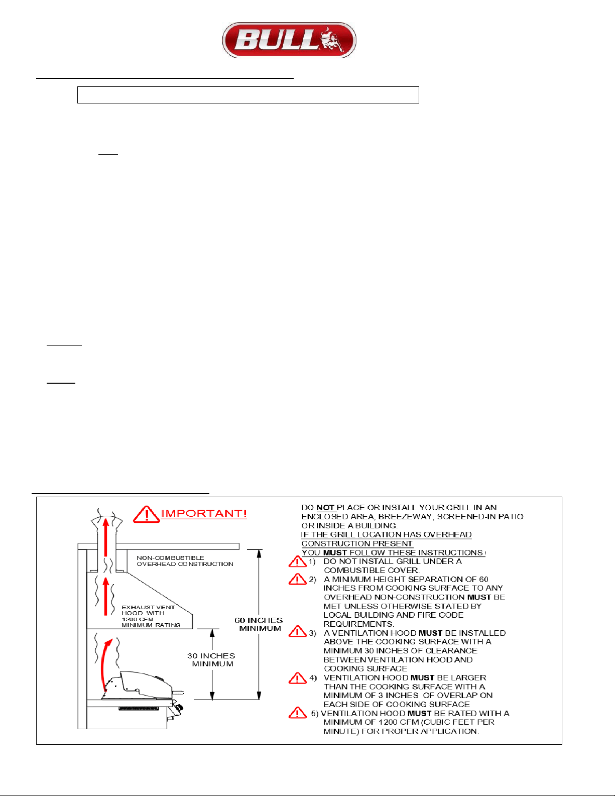
GRILL VENTILATION INSTRUCTIONS
PLEASE READ THESE INSTRUCTIONS BEFORE INSTALLING YOUR GAS
8
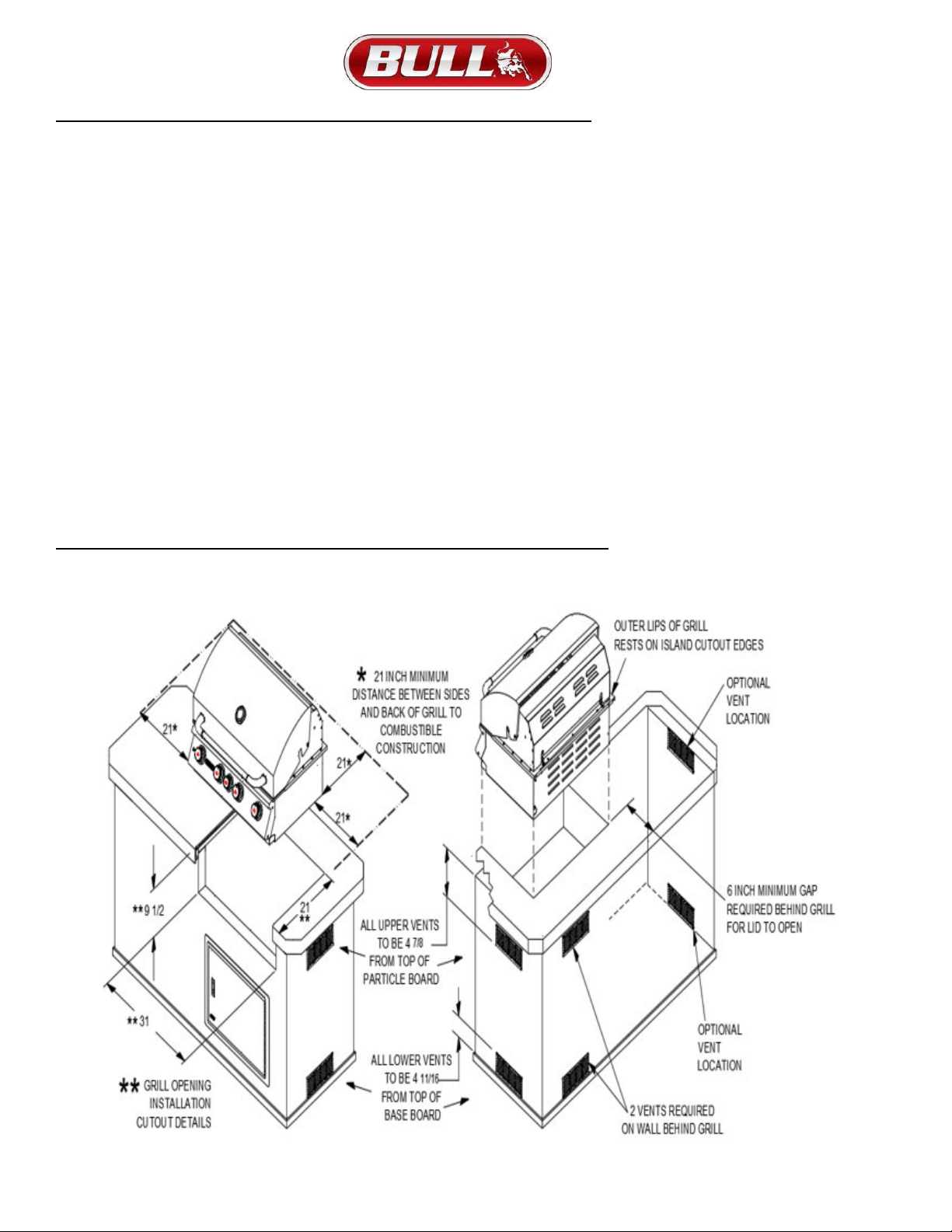
GRILL VENTILATION INSTRUCTIONS WHEN USING BUILT-IN CABINETS
1) Vents must be provided for combustion air and ventilation on both sides of built-in cabinet.
2) When choosing a location for your gas grill keep in mind that it should never be located under any overhead combustible
construction.
3) Per illustration, the sides and back of the grill should not be any closer than 21 inches to combustible construction.
4) Per CSA, it is required that any built-in cabinet must have enough room for only 1 LP tank. The LP tank enclosure must
not exceed (24.5” X 24.5” X 30”) and there must be a minimum clearance of 2 inches between the floor and the propane
tank enclosure.
(DO NOT STORE EMPTY OR FULL SPARE TANKS UNDER OR NEAR THIS OR ANY OTHER APPLIANCE)
5) There must be a minimum of 6 inches counter space behind the grill to allow the grill hood to clear properly.
6) The cylinder valve on the LP tank must be readily accessible for hand operation.
7) The LP tank must be isolated enough to where it is shielded from radiant heat and open flames.
8) The LP tank must be protected from foreign matter such as hot drippings.
9) There must be access so the LP tank can be connected, disconnected, inspected and leak tested outside of the cabinet.
10) The enclosure must provide access to allow leak testing of LP connections inside the enclosure for the LP Tank
11) The connectors must comply with ANSI Z21.75 CSA 6.27 standard for Connectors used on Outdoor Gas
Appliances and Manufactured Homes to be suitable for outside installation.
12) The instructions shall indicate that the maximum length of the connection shall be 6 ft.
13) Please ensure visibility of the connector and directions for the piping, flexible tubing and gas connector within enclosure.
14) Do not use any combustible materials for this construction.
GRILL AND VENT INSTALLATION DETAILS (DIMENSIONS ARE IN INCHES)
9
LIQUID PROPANE GRILL INSTALLATION SPECIFICATIONS
1) Vents must be provided for combustion air and ventilation on both sides of built-in cabinet.
2) When choosing a location for your gas grill keep in mind that it should never be located under any overhead combustible
construction.
3) The sides and back of the grill should not be any closer than 21 inches to combustible construction.
4) Per CSA, it is required that any built-in cabinet must have enough room for only 1 LP tank. The LP tank enclosure
must not exceed (24.5” X 24.5” X 30”) and there must be a minimum clearance of 2 inches between the floor and the .
(DO NOT store empty or full spare tanks under or near this or any other appliance.)
5) There must be a minimum of 6” counter space behind the grill to allow the grill hood to clear properly.
6) The cylinder valve on the LP tank must be readily accessible for hand operation. The tank must be isolated enough to where
it is shielded from radiation, open flames and protected from foreign matter such as hot drippings.
7) There must be access so the tank can be connected, disconnected, inspected and leak tested outside of the cabinet. As
well as access so that connections which could be disturbed when installing the tank in the cabinet can be leak tested inside
the cabinet.
8) The connector must comply with the Standard for Connectors for Outdoor Gas Appliances and Manufactured Homes, ANSI
Z21.75 • CSA 6.27, and suitable for outside installation. The instructions shall indicate that the maximum length of the connection
shall be 6 ft. Please ensure visibility of the connector and directions for supporting the piping, flexible tubing, or gas connector
within the built-in enclosure.
9) The LP gas supply cylinder(s) to be used must be constructed and marked in accordance with the Specifications for LP gas
Cylinders of the U.S. Department of Transportation (D.O.T.) or the Standard for Cylinders, Spheres and Tubes for Transportation
of Dangerous Goods and Commission, CAN/CSAB339, as applicable; and provided with a listed overfilling prevention device. And
provided with a cylinder connection device compatible with the connection for outdoor cooking appliances.
TO PERFORM GAS LEAK CHECK – REFER TO PAGE 4 OR 13

10
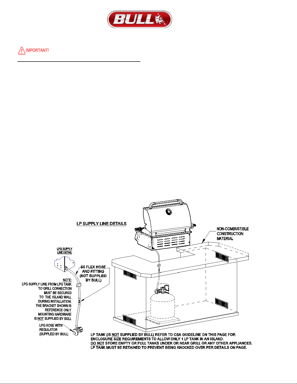
LP GAS TANK RETENTION GUIDELINES
NOTE: AN LP TANK (CYLINDER) WITHIN AN ENCLOSURE MUST USE A TANK RETENTION SYSTEM TO PREVENT BEING
KNOCKED OVER.
Below are the requirements with supportive illustrations for an LP Tank enclosure and how to install a Tank
Retention System which can be obtained through your Bull Dealer:
Per CSA the following is required that any built-in cabinet must have enough room for only 1 LP tank.
The LP tank enclosure must not exceed (24.5” X 24.5” X 30”) and there must be a minimum clearance
of 2 inches between the floor and the propane tank enclosure.
Any Tank Retention system must be securely fastened to the island floor using bolts with washers and nuts.
There must be a minimum clearance of 2 inches between the floor and the cylinder enclosure. Once secured,
place the LP tank in the tank retention system and tighten the tank retention bolts clockwise until the tank is
held snug and cannot move. Turn the retention bolt counter-clockwise to free the tank for removal.
WARNING:
DO NOT STORE AN EMPTY, SPARE OR DISCONNECTED LP GAS CYLINDER UNDER OR NEAR THIS GRILL
OR ANY OTHER APPLIANCE.
DO NOT USE A DENTED OR RUSTY LP GAS CYLINDER AS THIS MAY BE HAZARDOUS.
11
NATURAL GAS GRILL INSTALLATION SPECIFICATIONS
Refer to the following instructions and illustrations for typical gas supply connections.
We strongly suggest professional installation of your gas plumbing and connection to your grill
IMPORTANT: Before connecting grill to gas source, make sure BBQ Grill control knobs are in “OFF” position.
Be sure to follow instructions for connecting an appliance to a fixed fuel piping system specifying the use of a rigid pipe, semi-
rigid tubing, and/or a connector that complies with the Standard for Connectors for Outdoor Gas Appliances and Manufactured
Homes, ANSI Z21.75 For post-mounted outdoor cooking gas appliances, in-ground metallic posts shall be protected against
corrosion as warranted by soil conditions. A suitable coating of corrosion protection will retard the effects of corrosion and help
your Bull purchase last longer.
IMPORTANT INSTALLATION GUIDELINES:
1) Vents must be provided for combustion air and ventilation on both sides of built-in cabinet.
2) When choosing a location for your gas grill, keep in mind that it should never be located under any overhead combustible
construction.
3)The sides and back of the grill should not be any closer than 21 inches to combustible construction as shown in drawing below.
4)There must be a minimum of 6 inches counter space behind the grill to allow grill hood to clear properly.
5)
Do not use any combustible materials for this construction.
6)
Do not store empty or full spare gas tanks under or near this or any
other appliance.
NATURAL GAS CONNECTION TO GRILL
IMPORTANT:
Bull Outdoor Products does not recommend the use of any
quick connect fittings or lines to the unit. Use of these types of fittings or
lines could cause low gas flow and greatly reduce the performance of
the unit
.
1)
Do not use Teflon ® tape or pipe sealant on any flare ends
because you will not obtain a leak-free seal.
2)
Remove plastic cap from regulator installed on grill.
3)
Attach stainless steel flex line 3/8” flare-female end to the regulator.
4)
Attach the other end of flex line to shut-off valve through a nipple.
5)
Attach a shut-off valve to gas supply pipe.
TO PERFORM GAS LEAK CHECK – REFER TO PAGE 4 OR 13
12
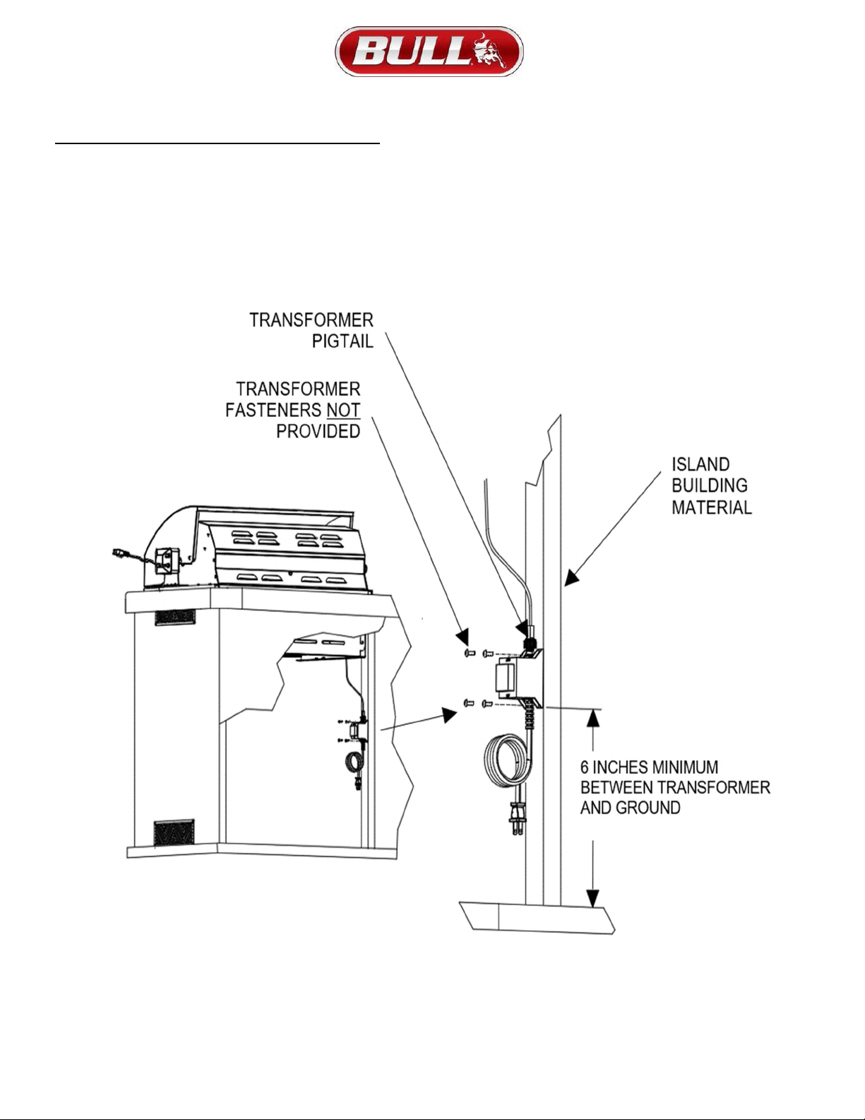
LIGHT SYSTEM TRANSFORMER INSTALLATION
NOTE: Per illustration below, the transformer must be installed at least 6” above the ground to ensure transformer and interior light system
longevity. The transformer has mounting holes so you can fasten to the frame inside your island or grill enclosure.
Since we don’t know what material, you’ll be mounting to you’ll need to provide your own fasteners to complete.
13
GRILL ‘FIRST USE’ LIGHTING PROCEDURE
• DO NOT SMOKE WHILE LIGHTING GRILL OR CHECKING GAS SUPPLY
• CONNECTIONS
BECOME FAMILIAR WITH THE SAFETY GUIDELINES AT THE FRONT OF
THE MANUAL
• DO NOT LEAVE GRILL UNATTENDED DURING USE
• DO NOT MOVE GRILL DURING USE
• TURN OFF GAS SUPPLY AFTER USING GRILL
• IT IS RECOMMENDED YOU USE PROTECTIVE GLOVES TO OPERATE THE GRILL WHEN HANDLING
ANY COMPONENTS WITH TRANSFERRED HEAT TEMPERATURE.
IMPORTANT! FOLLOW THE STEPS BELOW BEFORE FIRST USE OR AT START OF NEW GRILLING SEASON
1) If your grill fuel source is LP, check the gas cylinder to see if it’s full.
2) Check that the end of each burner tube is properly located over each valve orifice.
3) Wash flame tamers, cooking grids, and warming rack with warm, soapy water.
4) Rinse and dry thoroughly.
5) Season metal surfaces with cooking oil and occasionally throughout the season.
6) PERFORM LEAK TEST PER instructions below to ensure that there are no gas leaks before first use, after changing gas
tank or start of a new grilling season.
7) After cooking is completed, turn grill to high setting for NO MORE THAN five minutes to burn off excess grease or food residue.
LEAK CHECK INSTRUCTIONS
1) Turn off heat control valve(s), and then turn on gas at source.
2) Make a soap solution by mixing one-part liquid detergent and one-part water.
3) Apply the soap solution to all gas connections: bubbles will appear in the soap solution if connections are not
properly sealed. Tighten or repair as necessary.
4) If you have a gas leak that you cannot repair, turn off the gas at the source, disconnect fuel line from the grill and
immediately call your grill dealer and gas supplier for professional assistance.
5) Make sure all gas connections are securely tightened.
FIRST USE OR FIRST USE ‘BURN OFF’ GUIDELINES:
Always open lid before lighting. Do not move the appliance when it is in use.
NOTE: The gas lines and burners will be full of air after assembly or installation. Before lighting, please follow the steps below to
purge the gas lines and prime them with gas to properly ignite the burners on your grill. It may require several attempts at lighting the
burners before you are successful.
1)
With BBQ Grill control knobs in “OFF” position, turn on the Gas supply.
2)
Light any burner by pushing its control knob in fully and slowly (3 to 4 seconds) turning it about 1/4 turn to the left (counterclockwise)
until a click is heard. The 3 to 4 second duration should provide enough gas to light the burner. If the burner does not light,
immediately return the control knob to “OFF”, wait several minutes for the gas to disperse, and repeat the process. After burner lights
successfully, turn control knob to “OFF”.
3)
Repeat process for each control knob/igniter, in turn, ensuring that other knobs are in “OFF” position as you perform each check.
4)
You’ll need to perform a ‘burn off’ to the grill to get rid it of any odors or foreign matter by igniting the burners, closing the lid, and
operating at “HIGH”
setting for about five minutes. NOTE: Seasoning your grill is optional if you do use with cooking oil.
5)
If any burners fail to light after several attempts, discontinue gas supply at source and re-inspect for obstructions to gas flow and
orifices.
NOTE: TO LIGHT INFRARED BURNER, TURN KNOB AND WAIT ABOUT 10 SECONDS TO ALLOW GAS TO GET TO
BURNER BEFORE CLICKING IGNITION KNOB.
ALWAYS LIGHT THE GRILL WITH THE LID IN AN OPEN POSITION!
WARNING: IF THESE GUIDELINES ARE NOT FOLLOWED, FIRE CAUSING SERIOUS INJURY OR DEATH MAY OCCUR.
14
GRILL STANDARD LIGHTING PROCEDURE
DO NOT SMOKE WHILE LIGHTING GRILL OR CHECKING GAS SUPPLY CONNECTIONS!
Set ALL BBQ Grill control knobs to “OFF” and open gas supply, LP cylinder or
Natural Gas Valve.
LIGHTING MAIN BURNER(S):
1. Become familiar with the safety guidelines at the front of the
manual.
2. If your grill fuel source is a LP gas cylinder, check to see that cylinder is filled.
3. Check that the end of each burner tube is properly located over each valve orifice.
4. Make sure all gas connections are securely tightened.
TEST FOR LEAKS WITH A SOAP SOLUTION, NEVER WITH A FLAME.
(Gas Leak Check instructions are on page 4 & 13)
5. Always open lid before lighting.
6. Set ALL BBQ Grill control knobs to “OFF” and open gas supply, LP cylinder or at
Natural Gas Valve.
7. Ignite only the burners you intend to use, using the same method for each: Push in control knob completely and rotate slowly (3 to 4
seconds) about 1/4 turn to the left (counter-clockwise) until a click is heard. The 3 to 4 second duration should provide enough gas to
light the burner. If the burner does not light, immediately return the control knob to ‘OFF’, wait several minutes for the gas to disperse,
and repeat the process. After burner ignites, repeat procedure with any other burner needed.
8. Adjust control knob(s) to desired cooking temperature.
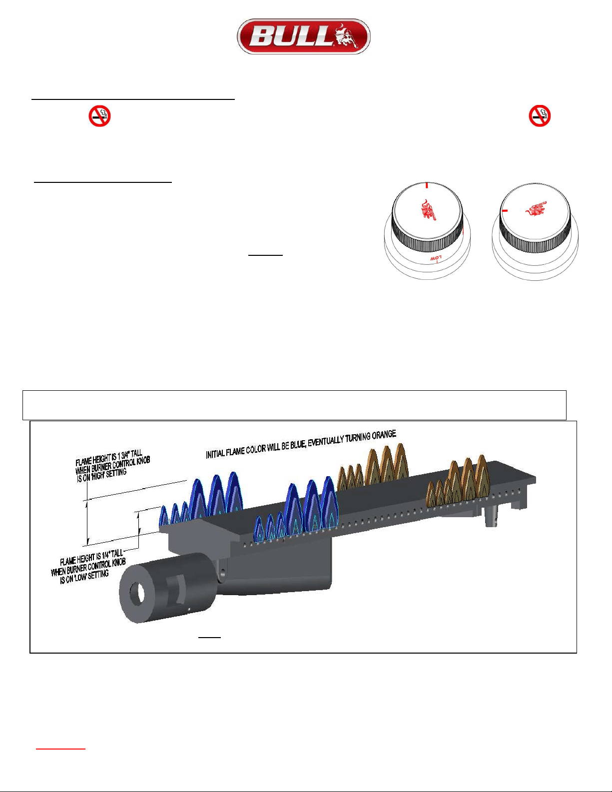
NOTE:
Initially, the Burner will have a blue flame (see illustration guideline below). After some time, the color of the flame will be orange.
9.
NOTE:
If igniters fail to produce a spark at the electrode tip, burners can be manually lit with a fireplace-type match.
See next page for instructions.
WARNING: IF THESE GUIDELINES ARE NOT FOLLOWED, FIRE CAUSING SERIOUS INJURY OR DEATH MAY OCCUR.
Control Knob
Control Knob
‘OFF’ Position HIGH’
If the burner does not light after several attempts,
immediately (or within 5 seconds?) return the control
knob to ‘OFF’,
wait 5 minutes fo
r
the
g
as to dis
p
erse
before re
p
eatin
g
the
p
rocess o
r
attem
p
tin
g
to
manuall
y
li
g
ht the
g
rill
p
e
r
NOTE: Flame color may not be evident in bright daylight
.
15
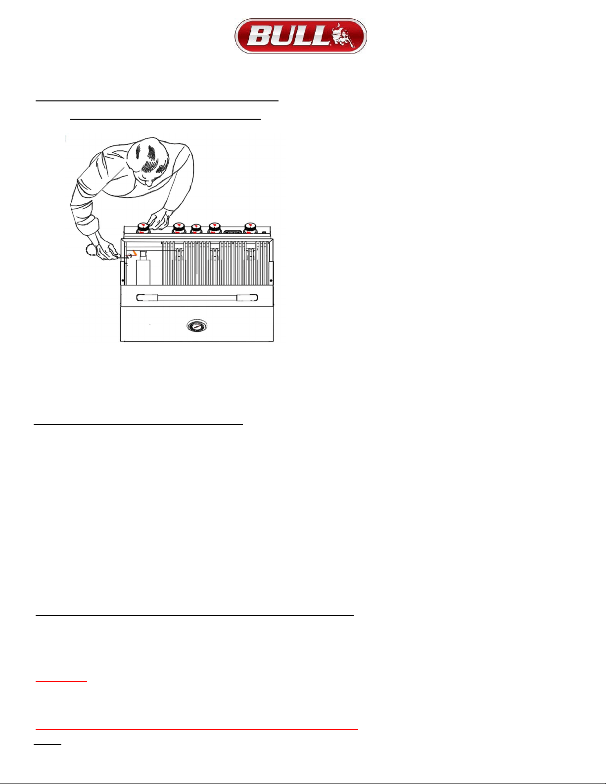
TO LIGHT GRILL WITH A FIREPLACE-TYPE MATCH
1.
NOTE:
To light gas grill with a fireplace-type match, follow steps 1 through 6 above. Remove cooking grid and flame tamer from
burner you wish to light. Using provided Lighting Rod to hold a lighted fireplace type match or long-necked butane lighter placing flame
near to burner ports. Press in control knob and rotate left to “HIGH” setting to release gas per illustration below:
Burner should light immediately. If more than one burner is needed, repeat procedure with each burner.
2. Replace flame tamer and cooking grid. Turn off burners not needed and adjust other burners to desired cooking temperature.
LIGHTING INFRARED ROTISSERIE BURNER
The rear infrared rotisserie burner allows for slow rotisserie cooking of meats and poultry. Infrared burners radiate heat onto the outer
surface of the food. This allows cooking without the grease drippings burning on the flame tamers.
NOTE: THIS CONTROL HAS A FIXED SETTING AND IS NOT ADJUSTABLE.
DO NOT ATTEMPT TO REGULATE THE ROTISSERIE BURNER BY USING THE CONTROL KNOB.
TO LIGHT ROTISSERIE BURNER
1)
CAUTION:
Always open lid before lighting.
2)
Set ALL BBQ Grill control knobs to “OFF” and open gas supply, LP cylinder or Natural Gas Valve.
3)
The rotisserie control knob is located at the middle of the Control Panel. Push in control knob completely and rotate slowly (5 to 10
seconds) about 1/4 turn to the left (counter clockwise) until a click is heard. The 5 to 10 second duration should provide enough gas to light
the burner. If the burner does not light, immediately return the control knob to “OFF”, wait several minutes for any accumulated gas to clear
out of the grill.
4)
Keep lid closed and operate burner at the “ON” position when using rotisserie.
TO LIGHT ROTISSERIE BURNER WITH A FIREPLACE-TYPE MATCH
Follow steps 1 & 2 above. Carefully insert lighted fireplace-type match or long-necked butane lighter placing flame near to the Ceramic
Panel. Press in control knob and rotate left (counter clockwise) to “HIGH” or “ON” setting to release gas. Burner should light immediately.
WARNING:
NEVER OPERATE ROTISSERIE BURNER WITH MAIN BURNER(S) “ON”
WARMING RACK MUST BE REMOVED WHEN OPERATING THE ROTISSERIE BURNER
ALWAYS LIGHT THE GRILL WITH THE HOOD IN AN OPEN POSITION!
NOTE:
Rotisserie burner may take a few attempts to ignite.
16
COOKING COMPONENT INSTALLATION, CAUTION, BEFORE YOU START:
1)
Turn off the gas supply at the gas supply source first
2)
It is recommended you protective gloves to operate the grill when handling any components with transferred heat temperature.
3)
Do not move the grill during use.
4)
Check gas valve orifices, burner tubes and burner ports for any obstructions
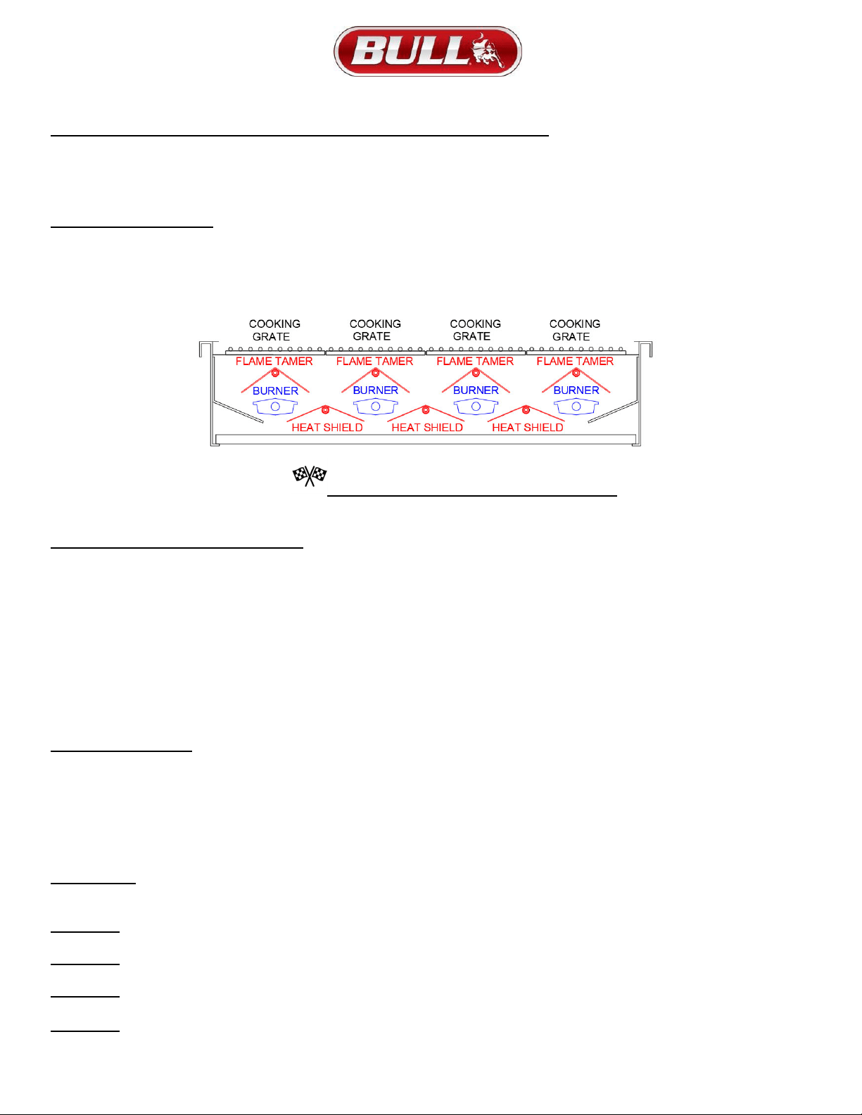
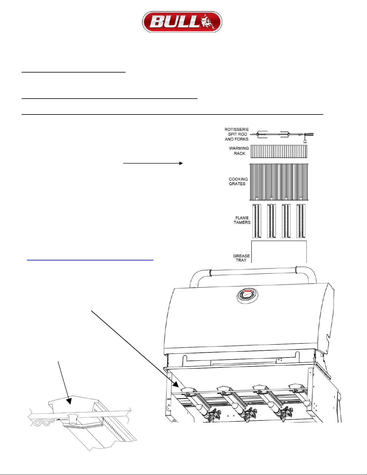
PER DRAWING BELOW:
5)
Place stainless steel heat shields on lowest ledge under / between burners in grill insert.
6)
Place stainless steel flame tamers on lower ledge above burners in grill insert.
7)
Place cooking grates in grill insert on ledge above flame tamers.
8)
Please read Safety, Lighting and Operating Instructions carefully.
NOW YOUR GAS GRILL IS READY TO USE!
ANY MODIFICATION OF THE APPLIANCE MAY BE DANGEROUS TO YOU OR OTHERS AND MAY VOID PRODUCT WARRANTY
COOKING TEMPERATURE SETTINGS
HIGH SETTING
Use this setting only for fast warm-up, for searing steaks and chops, and for burning food residue from the cooking
grids after the cookout is over.
MEDIUM SETTING
Use this setting for most grilling, roasting or baking, and for cooking hamburgers and
vegetables.
LOW SETTING
Use this setting for all smoke cooking, rotisserie cooking, and when cooking very lean cuts such as fish.
NOTE:
These temperatures vary with the outside temperature and the amount of wind.
PRE-HEATING: It is necessary to preheat the grill for a short time before cooking certain foods, depending on the type of
food and the cooking temperature. Food that requires a high cooking temperature will need to preheat for five minutes; food
that requires a lower cooking temperature needs only a period of two to three minutes. There is no need to preheat for
casseroles or other foods that require slow cooking.
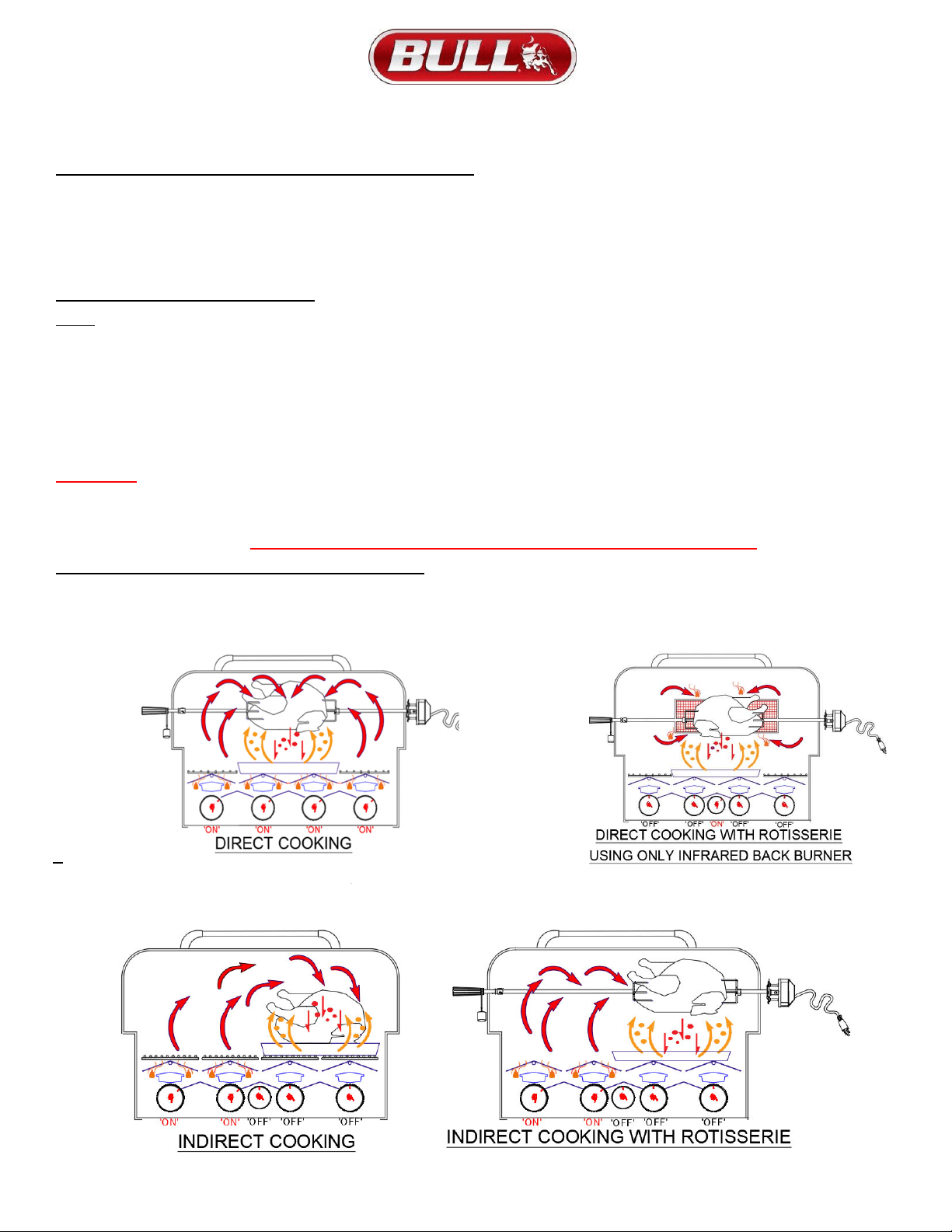
COOKING METHODS
You can cook poultry and large cuts of meat slowly to perfection on one side of the grill by indirect heat from the next burner
or with infrared rotisserie burner. The heat from the lighted burner circulates gently throughout the grill, cooking the meat or
poultry without any direct flame beneath or below the food you are preparing. This method greatly reduces flare-ups when
cooking extra fatty cuts, because there is no direct flame to ignite the fats and juices that drip down during cooking. Place a
drip pan slightly smaller than the cut of meat on the cooking grids or flame tamer surface under the meat being cooked. This
will allow you to catch meat juices for making gravy.
FLARE-UPS:
The fats and juices that drip from the meat cause flare-ups. Since flare-ups impart the distinctive taste and color to food
cooked over an open flame, they should be expected and encouraged within reason.
CAUTION: Uncontrolled flaring can result in a ruined meal. To control excessive flare-ups caused by too high a heat setting,
turn the heat control knob to a lower setting.
CAUTION: If burners go out during operation, close gas supply at source, and turn all gas valves off. Open lid and wait five
minutes before attempting to re-light (this allows accumulated gas fumes to clear).
CAUTION: Should a grease fire occur, close gas supply at source, turn off all burners and leave lid closed until fire is out.
Do not use water or any liquid to extinguish a grease fire.
CAUTION: Do not attempt to disconnect any gas fitting while your barbecue is in operation or while gas feed is on.
17
ROTISSERIE SYSTEM INSTALLATION TO ANGUS GRILL
1) The trolley thumb screw should be located on the inside of the grill, screw the knurled nut on next, the counterweight is then
added and then screw on the black handle.
2) To adjust the counterweight, loosen the black handle and slide the counterweight up or down to properly position the weight
of the food being cooked. The purpose of the counterweight is to balance the rotation and prevent lopsided movement of the
motor.
ROTISSERIE SYSTEM OPERATION
NOTE: FOLLOWING THE GUIDELINES BELOW WILL PREVENT STRAINING YOUR ROTISSERIE SPIT ROD AND MOTOR
1) DO NOT EXCEED 20 lb. MAX WEIGHT CAPACITY
2) THE ITEM YOUR PREPARING NEEDS TO BE PLACED IN A BALANCED POSITION ON THE ROTISSERIE SPIT ROD.
3) BEFORE LIGHTING THE INFRARED BURNER CHECK TO MAKE SURE THE MEAT DOES NOT HIT THE INFRARED BURNER
WHILE TURNING.
4) BEFORE LIGHTING THE INFRARED BURNER CHECK TO MAKE SURE THE MEAT DOES NOT HIT THE INFRARED BURNER
WHILE TURNING.
WARNING:
NEVER OPERATE ROTISSERIE BURNER WITH MAIN BURNER(S) “ON”
WARMING RACK MUST BE REMOVED WHEN OPERATING THE ROTISSERIE BURNER
ALWAYS LIGHT THE GRILL WITH THE HOOD IN AN OPEN POSITION!
ROTISSERIE COOKING OPTIONS (ANGUS GRILL)
Rotisserie is mostly used to cook large pieces of meat and poultry to assure slow, even cooking. The constant turning
provides a self-basting action, making food cooked on a rotisserie exceptionally moist and juicy. Rotisserie cooking generally
requires 1 ½ to 4½ hrs. to cook depending on the size and type of meat being cooked.
ROTISSERIE COOKING WITH INDIRECT HEAT
Since indirect heat is often used in cooking on a rotisserie, a foil or aluminium drip pan is advisable to prevent excessive
flare-ups. Generally, the cooking grates are removed to allow for the swing of the rotisserie. A basting pan can be placed
under the rotisserie area on top of the flame tamer(s) to catch the drippings
.
18
BURNER REMOVAL INSTRUCTIONS
Your grill has 4 cast stainless steel burners that have cotter pins to keep the burners in place during shipping. You’ll need to remove the
cotter pins to allow burner removal for inspection and or cleaning. The cotter pins can be discarded or retained in case the grill is relocated.
If your grill has the gas supply already installed, please follow these safety instructions.
SAFETY INSTRUCTIONS PRIOR TO REMOVAL OF BURNERS:
Always
follow these instructions below prior to burner removal.
NOTE: TO REDUCE THE CHANCE OF FLASHBACK, THE PROCEDURES BELOW SHOULD BE FOLLOWED
1) Do not attempt during or right after use. Allow Grill to cool long enough to touch inside.
2) Always turn off the gas supply prior to cleaning your grill.
3) Gas control knobs should be in the “OFF” position.
4) Fuel line should be disconnected from the gas valve manifold.
(Cotter Pin Removal)
These items should be removed first.
1) Cotter Pin Location, go to the back side of the grill and look
underneath inside of the back panel at the spot where you
pulled the out the grease tray. That is where the cotter pins are
located to secure the cast burners to the grill during
transit.There you will see the a peg at the end of each cast
burner protruding through the grill wall and secured with a
cotter pin.
2) Cotter Pin Removal, Below on the left shows how the cotter
pin is removed from the standard burners. The cotter pins can
be removed with a set of pliers. There is no need to replace the
pliers, they are for shipping purposes
only.
You can also refer to our video for help at
https://www.youtube.com/watch?v=yhlJR5svLSA
Each burner is held to
the grill by a cotter pin.
The detail below
shows how to remove
the cotter pin.
Detail view showing cotter
pin pulled from peg to
release burner from grill.
19
REMOVING CAST SST BURNERS FROM YOUR GRILL (CONTINUED)
BURNER INSPECTION INSTRUCTIONS: BURNER CLEANING INSTRUCTIONS:
After burners are removed
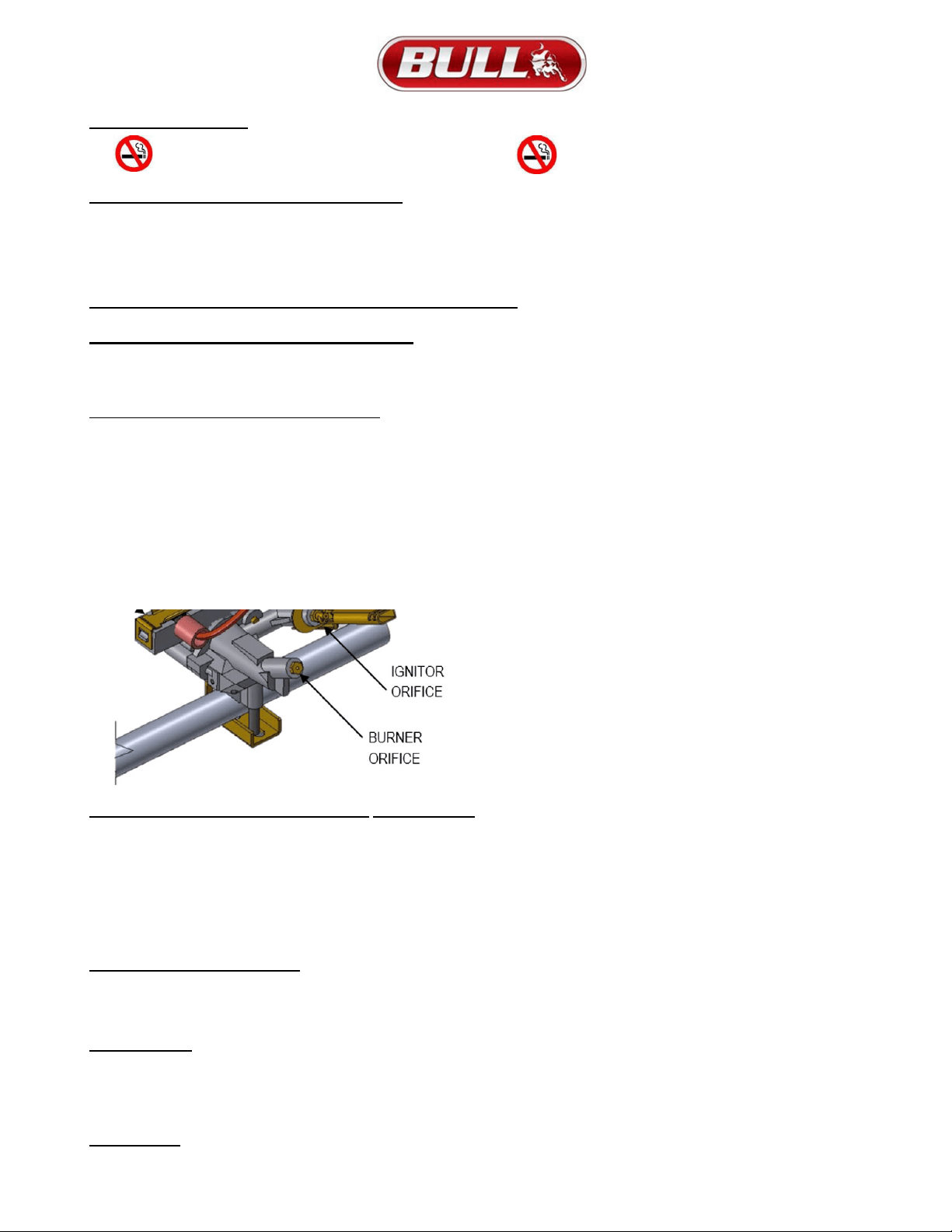
1) First check the following areas shown below to verify they
are damage free and clear of debris.
2) Monthly inspection of the burners for damage (cracks or holes) or any
openings caused by corrosion. If such damage is found, order and install a
new burner.
3) After installation, check to ensure the gas valve orifices are correctly placed
inside ends of burner tubes.
Be sure follow the cleaning instructions after inspection.
INSERTING BURNER INTO GRILL
CAUTION- ALWAYS TURN OFF GAS SUPPLY PRIOR
To remove burners, remove cotter pin and lift the burner out of the retaining hole enough to clear so you slide the burner free from the
gas valve tip as shown. To re-install burners, install burner back on gas valve tip far enough to allow the burner retainer post to go
back into retainin
g
hole on
g
rill.
1) Wire brush entire outer surface of burner to remove food
residue, dirt or loose corrosion.
2) Bend a stiff wire (a light-weight coat hanger works well)
into a small hook as shown. Run the hook through each burner tube
several times.
3) Use a narrow bottlebrush with a flexible handle. Run the
hook through each burner tube and burner several times.
4) Wire brush entire outside surface of burner to remove
loose corrosion.
5) Clean any clogged hole with a stiff wire (such as an open
paper clip).
6) Inspect the burner assembly for any openings caused by
corrosion.
FOR ANGUS GRILLS
20
INSTALLING BURNERS BACK IN GRILL
Note, there’s no need to use the cotter pin while installing the back into position. If is for shipping purposes only.
IMPORTANT NOTE Check the burner to make sure it is proper located after replacing.
Make sure the valve orifices are inside the burner tubes (see illustration below).
WARNING
If the valve orifices do not fit inside the burner tubes, lighting the burners may cause and explosion and/or fire.
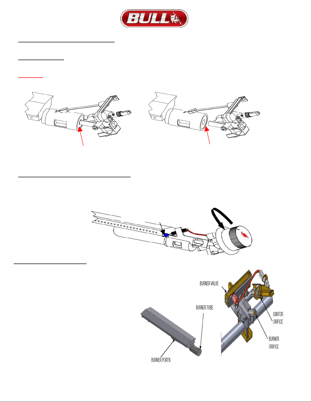
BURNER IGNITOR / ELECTRODE INSPECTION
With all control knobs set to “OFF”, in turn, push each control knob in fully and turn slowly about a 1/4 turn to the left (counter clockwise)
until a click is heard and you should see a blue spark at the electrode tip. If no spark is seen refer to page 22 for troubleshooting. Return
control knob to “OFF” before checking next igniter.
BURNER OPERATION CHECK
1) With BBQ Grill control knobs in “OFF” position,
turn on the Gas supply.
2) Light any burner by pushing its control knob in
fully and slowly (3 to 4 seconds) turning it about 1/4
turn to the left (counter clockwise) until a click is
heard. The 3 to 4 second duration should provide
enough gas to light the burner. If the burner does
not light, immediately return the control knob to
“OFF”, wait several minutes for the gas to disperse,
and repeat the process. After burner lights
successfully, turn control knob to “OFF”.
3) Repeat process for each control knob/igniter, in turn,
ensuring that other knobs are in “OFF” position as you
perform each check.
If any burners fail to light after several attempts,
discontinue gas supply at source and re-inspect
for obstructions to gas flow and orifices.
CORRECT
POSITION
INCORRECT POSITION
NOTE GAP BETWEEN
BURNER TUBE
AND BURNER ORIFICE
BLUE SPARK
WILL BE SEEN
HERE AT
ELECTRODE TIP
TURN BURNER KNOB
¼ TURN
COUNTER CLOCKWISE
21
GRILL LIGHTING SYSTEM
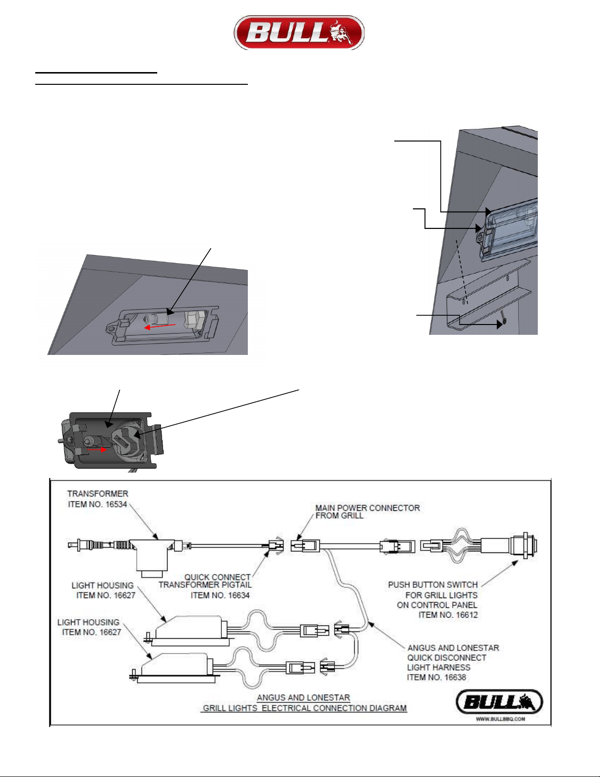
LIGHT BULB REPLACEMENT INSTRUCTIONS
1) Remove screw with a small Phillips screwdriver. Caution: Glass
cover may be loose, ensure the cover is properly supported before
completely removing the screw.
2) There is a metal clip that clamps onto the glass cover and
snaps into the light housing on the screw end. Unsnap the
cover by carefully prying apart the metal clip from the light
bulb housing. Once unsnapped, slide the cover out and
away from the housing and set somewhere safe.
3) Remove old light bulb by pulling the bulb out of the housing
(make sure bulb is cool before removal
4) Using a soft cloth or paper towel, replace new light bulb into the housing (fingerprints left on the bulb may reduce its life). Make
sure the metal prongs on the light bulb slip into the openings in the light housing
GLASS
COVER
LIGHT BULB
HOUSING
MOUNTING
SCREW
LIGHT BULB

22
ANNUAL CLEANING & MAINTENANCE
(1) Keeping outdoor cooking gas appliance area clear and free from combustible materials, gasoline and other
flammable vapors and liquids.
(2) Not obstructing the flow of combustion and ventilation air.
(3) Keeping the ventilation opening(s) of the cylinder enclosure free and clear from debris.
Visually checking burner flames including pilot burner flame if provided, with pictorial representations.
CLEANING THE COOKING GRATES:
After cooking, turn control knobs to “OFF” and let grill cool before attempting to clean your cooking grids.
Before first use and periodically it is suggested that you wash the cooking grids in a mild soap and warm water
solution. You can use a washcloth or a vegetable brush to clean your cooking grids
.
CLEANING THE FLAME TAMERS & HEAT SHIELDS
Washing the flame tamers & heat shields after every use is not necessary but periodically it is suggested you
wash them in a soap and warm water solution. Use a wire brush to remove stubborn burned on cooking
residue. Dry the flame tamers & heat shields thoroughly before you reinstall it in the cooking insert.
CLEANING THE GREASE TRAY
The grease tray should be emptied and wiped down periodically and washed in a mild detergent and warm water solution.
ANNUAL CLEANING OF GRILL HOUSING
Burning-off the grill after every cookout will keep it ready for instant use. However, periodically the grill should
be given an entire thorough cleaning to ensure optimal performance.
1) Shut off gas supply at source and disconnect fuel line from gas valve manifold. Protect fuel line fitting.
2) Remove and clean (as explained above) the cooking grids, flame tamers and burners.
3) Remove warming rack and wash with mild detergent and warm water.
4) Cover the gas valve orifices with a piece of aluminium foil.
5) Brush the inside and bottom of the grill with a stiff wire brush and wash down with a mild soap and warm
water solution. Rinse thoroughly and let dry.
IMPORTANT: DO NOT line the bottom of the grill housing with aluminium foil, sand or any other grease
absorbent substance. Grease will not be able to drip down into the grease collector and a grease fire could
occur. It is that you use Bull Grease Tray Liners for ease clean up and maintenance.
STAINLESS STEEL CLEANING AND MAINTENANCE
Your Grill’s outstanding lustre and durability is attributed to Stainless Steel construction. The Stainless Steel
has an outer layer that relies on a proper cleaning and maintenance routine as the best way to remain intake
and prevent corrosion. Please note, Stainless Steel is not ‘rust proof’ contrary to popular belief. Grills are at
higher risk of corrosion by exposure to chemicals, caustics and fertilizers from swimming pools and outdoor
landscaping. Locations with climates with greater heat and humidity will intensify this condition. By following
a proper cleaning routine, you will add to the years you enjoy your Bull grill.
23
CLEANING (CONTINUED)
REQUIRED INSTALLATION, OPERATION AND MAINTENANCE INSTRUCTIONS THAT MUST BE FOLLOWED PER
ANSI Z210.58-CSA 1.6-2019 SECTION 4.24.2a FOR ALL OUTDOOR COOKING GAS APPLIANCES.
I. Installation must conform with local codes or, in the absence of local codes, with either of the following as applicable:
a. National Fuel Gas Code, ANSI Z223.1/NFPA 54
b. National Gas and Propane Installation Code, CSA B149.1
c. Propane Storage and Handling Code. CSA B149.2
d. Standard for Recreational Vehicles, ANSI A119.2/NFPA 1192 OR Recreational Vehicle Code, CSA Z240 RV Series
II. If an electrical source is utilized, the outdoor cooking gas appliance, when installed must be electrically grounded in
accordance with local codes, or in the absence of local codes with the refer to National Electrical Code, ANSI/INFPA 70
or Canadian Electrical Code, Part 1, CSA C22 the following as applicable:
III. This outdoor cooking gas appliance shall be used only outdoors and shall not be used in a building, garage or any
enclosed area.
IV. This outdoor cooking appliance is not intended to be installed in or on boats
V. This outdoor cooking appliance is not intended to be installed in or on recreational vehicles
VI. Do not remove any labels, nameplate or data plate that show the manufacture’s, distributor’s, jobber or dealer’s name,
manufactures address, model name or serial number.
VII. YOUR GRILL’S MINIMUM CLEARANCE FROM THE BACK AND SIDE OF ANY COMBUSTIBLE CONSTRUCTION MUST BE AT
21 INCHES MUST NOT BE UNDER OVERHEAD COMBUSTIBLE CONSTRUCTON.
REFER TO MANUAL PAGES LISTED BELOW FOR GRILL INSPECTION, MAINTENANCE OR SAFETY GUIDELINES:
PAGE 25 -32 INFO AND LOCATIONS FOR ORDERING REPLACEMENT PARTS
PAGE 17 AND 32
ROTISSERIE INSTALLATION TO GRILL
PAGE 3
CHECKING AND CLEANING OF BURNER/VENTURI TUBES OF INSECTS AND INSECT NESTS.
A CLOGGED TUBE CAN LEAD TO FIRE BENEATH THE GRILL.
REQUIRING OUTDOOR GAS APPLIANCE ARE TO BE CLEAR AND FREE OF COMBUSTIBLE MATERIALS, GASOLINE, OR
OTHER LIQUIDS EMITTING FLAMMABLE VAPORS.
DO NOT ALLOW OBSTRUCTION OR RESTRICTION TO THE FLOW OF COMBUSTION AND VENTILATION AIR AROUND THE
GRILL HOUSING.
KEEPING THE VENTILATION OPENING OF THE CYLINDER ENCLOSURE FREE AND CLEAR FROM DEBRIS.
KEEPING ELECTRICAL SUPPLY CORD AND FUEL SUPPLY HOSE AWAY FROM ANY HEATED SURFACES.
PAGE 4 OR 13 GAS LEAK TESTING PROCEDURES
PAGE 5 LP HOSE INSPECTION PRIOR TO EACH USE. ENCLOSED GRILLS MUST HAVE ACCESS TO INSPECT THE HOSE AND
CONNECTIONS. UPON INSPECTION, A HOSE WITH ANY CUTS, SLITS, TEARING, EXCESSIVE ABRASION OR WEAR.
MUST BE
REPLACED, DO NOT USE. REFER TO PAGES 3, 4 AND 5 TO ORDER REPLACEMENT LP HOSE.
PAGE 19 BURNER INSPECTION INSTRUCTIONS THAT SHOULD BE DONE MONTHLY.
PAGE 13-15
INSTRUCTIONS AND ILLUSTRATIONS FOR LIGHTING AND GRILL CONTROL OPERATION.
INSTRUCTIONS AND ILLUSTRATIONS FOR VISUALLY CHECKING THE BURNER AND PILOT FLAME
PAGE 19
IMPORTANTANCE OF BURNER ORIFICES BEING PROPERLY INSERTED INTO THE BURNER TUBES.
PAGE 22
CLEANING THE GRILL, INCLUDING SPECIAL SURFACES AND RECOMMENDED CLEANING AGENTS.
24
TROUBLESHOOTING
NEVER SMOKE DURING TROUBLESHOOTING
IF GRILL FAILS TO OPERATE PROPERLY
1) Turn off gas at source, turn control knobs to “OFF”, and wait five minutes before trying again.
2) Check gas supply/connections.
Repeat lighting procedure. If Grill still fails to operate properly, TURN “OFF” GAS AT SOURCE, TURN CONTROL KNOBS
TO “OFF”, wait for grill to cool, and check for the following potential causes below and how to address:
MISALIGNMENT OF BURNER TUBE(S) OVER ORIFICE(S) / CORRECTION:
Reposition burner tube to properly seat over orifice.
OBSTRUCTION IN GAS LINE /CORRECTION:
1) Remove fuel line from grill.
2) Open gas supply for one second to blow any obstruction from fuel line.
3) Close off gas supply at source and reconnect fuel line to grill.
PLUGGED BURNER ORIFICE/ CORRECTION:
To access a Burner Orifice:
1) Start by following to the instructions on pages 23 and 24 to allow Burner removal and inspection.
2) Next, carefully lift each burner up and away from gas valve orifice. Remove the orifice from each burner up and away from
gas valve and gently clear any obstruction with a fine wire. If an obstruction is suspected in gas valve(s) or gas valve
bracket, please contact your gas grill dealer or gas appliance service person for assistance.
3) Re-install the orifice.
4) Per page 26 reinstall burners over orifices and seat each burner peg. Perform Burner ignitor test to confirm it is working.
5) Replace cooking components and grease collectors before attempting to light grill.
MISALIGNMENT OF IGNITER ON BURNER / CORRECTION:
• Check for proper position of electrode tip. The tip of the electrode should be pointing forward toward the front
and free from grease for spark discharging. The ignition wire should be firmly connected to the valve ignition and
electrode.
• Replace the ignition wire if the wire is broken or cracked. With gas supply closed and all control knobs set to
“OFF”, check each positive igniter individually for presence of spark at electrode. In turn, push each control knob
in fully and rotate about 1/4 turn to the left (counter clockwise) until click is heard; the trigger hitting the strike
block should produce a blue spark at the electrode tip. Return control knob to “OFF” before checking next igniter.
IF RE-IGNITION IS NECESSARY
While the gas grill is still hot, you must wait for a minimum of five minutes before commencing to re-ignite (this allows
accumulated gas fumes to clear). If all checks/corrections have been made and gas grill still fails to operate properly,
consult your grill dealer or gas appliance service person.
FLAME COLOR
• Once the entire burner is operating, check the flame color to be sure it is mostly blue (some yellow color will be present because of impurities in the
fuel).
• If the flame is golden or yellow in color the reason could be seasoning salts, oil film, or other foreign matter on burner.
CORRECTION:
Remove burners and use compressed air to blow out residue from interior of burner.
FLASH BACK When fire occurs in and around the burners, immediately turn off gas at its source and turn the control knob(s) to “OFF”.
Wait until the grill has cooled, then clean the burners and burner ports as described on page 19.
25
REGISTERING YOUR GRILL
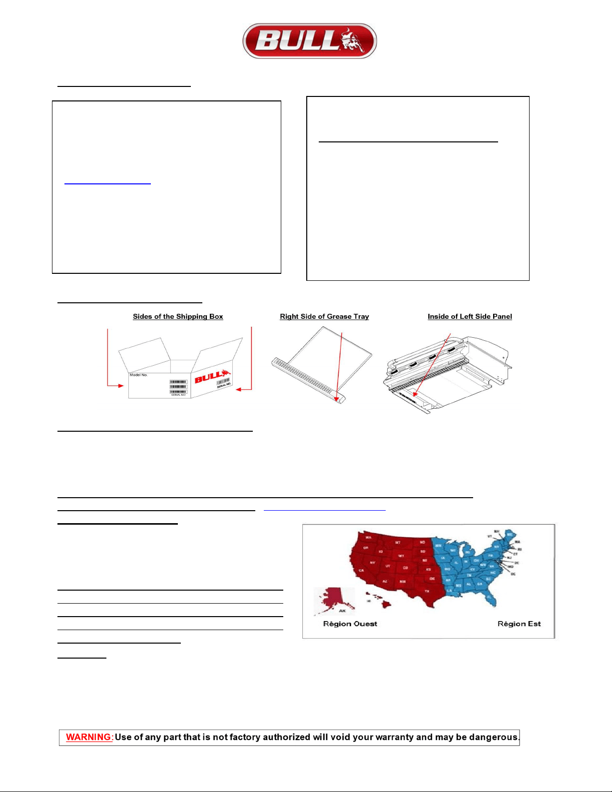
SERIAL NUMBER LOCATIONS
HOW TO ORDER REPLACEMENT PARTS
This is where your Product Information Reference Card will come in handy for supplying necessary info needed by
your Bull Authorized Dealer to assure you get the correct part(s) for your Grill or additional accessories to keep your
Grill in top working condition. If you don’t have the card, you can still get the model number and serial number on the
inside of the left side panel. That information is required for parts orders
.
Please refer to your owner’s manual parts list and illustration to identify what you need.
To Order Replacement Parts on-line go to:
https://www.bullbbq.com/buy-parts
Ordering Parts by phone:
Bull is ready to help with two regional suppliers
open 8:00 am to 5:00 pm Monday through Friday.
For the Western Region, call (800) 258-6810
For the Eastern Region, call (800) 229-3056
INSPECT YOUR SIDE CART FOR ANY DAMAGE
AND CONTACT OUR SERVICE CENTER OR
LOCAL DEALER FOR REPLACEMENT OF ANY
DAMAGED PARTS. IF DAMAGED DO NOT
ATTEMPT INSTALLATION.
CAUTION: REGARDING CONVERTING YOUR GRILL FROM
LIQUIDPROPANE TO NATURAL GAS OR VISA-VERSA.
Your Grill’s gas valve is pre-set at the factory specifically for the gas the Grill was intended for. That means a
different or specific gas valve must be installed when converting from one type of gas to another. Before you
start, be sure to contact your gas supplier or your Bull Grill Dealer who will be ready to supply the correct
conversion kits needed.
Thank you for purchasing your Bull Outdoor Products
Grill. To validate your Limited Warranty, you must
submit the completed the Warranty Registration Form
within 90 days from the date of purchase. Registration
can be completed on-line at
Submit ticket (ladesk.com) or by sending the completed
Warranty Registration Form and copy of your
Purchase Receipt or Invoice as proof of purchase to:
BULL OUTDOOR PRODUCTS, INC.
1011 East Pine St. Lodi,CA95240
Attn: Warranty Service Center
For Warranty Claims or Replacement Parts ordering,
please fill out the area provided below:
PRODUCT INFORMATION REFERENCE CARD
1) Model #______________________________
2) Serial #_______________________________
(The Serial Number is encoded with essential information
for ordering replacement parts or submitting Warranty
claims. Location of Serial Numbers is shown below)
3) Date of Purchase______________________
4) Copy of your Purchase Receipt or Invoice.
Warranty Questions call Customer Service at (800) 521-2855
26
OUTLAW GRILL REPLACEMENT PARTS LIST
MODELS 26038 LP & 26039 NG (
Any item with a
*
next to it requires a serial number)
# NO. USED IN
PARTS LIST
ILLUSTRATION
(NEXT PAGE)
BULL
PART NO.
PART DESCRIPTION
* INDICATES GRILL
SERIAL NUMBER REQUIRED
QTY
WARRANTY
PERIOD
(YEARS)
1
47003 INSERT
A
SSEMBLY
(
2016 & OLDER MODELS
)
1
Lifetime
2
47023 INSERT
A
SSEMBLY
(
2017 & NEWER MODELS
)
1
Lifetime
3
47019 LID - FRONT
1
1
4
16635 RUBBER BUMPER FOR LID
2
1
5
47031 LID - REAR
(
2016 & OLDER MODELS
)
1
1
6
47032 LID - REAR
(
2017 & NEWER MODELS
)
1
1
7
47012 COVER - REAR LID
1
1
8
47022 COVER - REAR LID
(
2017 & NEWER MODELS
)
1
1
9
47008 BACK PANEL
(
2016 & OLDER MODELS
)
1
1
10 47024 BACK PANEL
(
2017 & NEWER MODELS
)
1
1
11 47011 GREASE TRAY
1
1
12 97022 LIGHTING ROD WITH CHAIN
1
1
13 16670 HEAT SHIELD
3
3
14 26104 RELIABULL PORCELAIN BURNER
4
2
15 16631 VENTED FLAME TAMER
4
3
16 16517 COOKING GRATE
4
Lifetime
17 47004 WARMING RACK
1
3
18 16522 LID HANDLE END CAP
2
3
19 16523 LID HANDLE CENTER BA
R
1
3
20 16690 LARGE TEMPERATURE GAUGE
1
1
21 16692 LARGE TEMPERATURE GAUGE BEZEL
1
1
22 26101 CONTROL PANEL
1
1
23 16629 BEZEL - MAIN BURNER
4
1
24 16613 KNOB - MAIN BURNER
4
1
25
16525
GAS VALVE - MAIN BURNER
(
LIQUID PROPANE MODEL ONLY
)
4
1
26
16589
LP HOSE AND REGULATOR
(
LIQUIDE PROPANE MODEL ONLY
)
1
1
27
16598
FLARE TO FLARE UNION
(LIQUID PROPANE MODEL ONLY)
1
1
28
16524
GAS VALVE-MAIN BURNER
(
NATURAL GAS MODEL ONLY
)
4
1
29
16507
REGULATOR
(
NATURAL
GAS
MODEL
ONLY
)
1
1
30 16599
REGULATOR
ADAPTER
(
NATURAL
GAS
MODEL
ONLY
)
2
1
31 47005 MANIFOLD
1
3
32 47006 STAINLESS FLEX TUBE
1
1
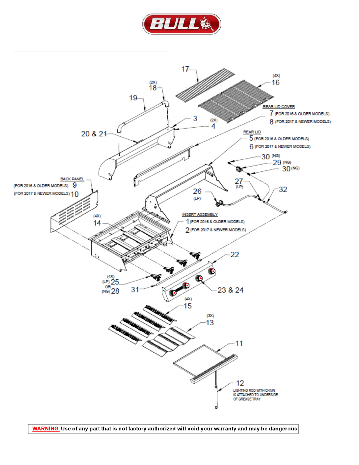
27
OUTLAW GRILL REPLACEMENT PARTS ILLUSTRATION
28
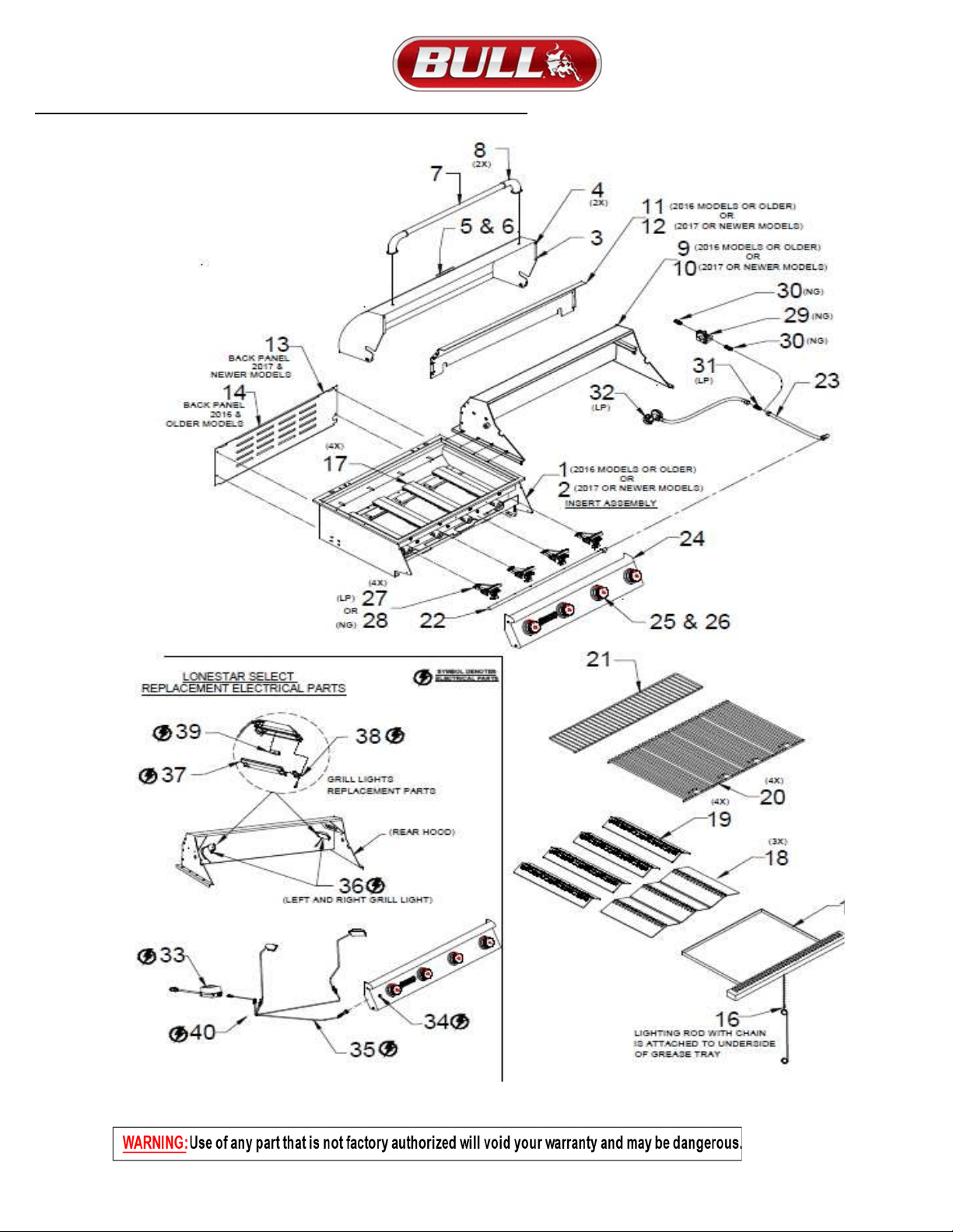
LONESTAR SELECT GRILL REPLACEMENT PARTS LIST
MODEL #87048 LP & #87049 NG (
Any item with an * next to it requires a serial number)
NUMBER USED ON
ILLUSTRATION, PG 33
BULL
PART NO.
DESCRIPTION
* SERIAL NUMBER REQUIRED
QTY
WARRANTY
PERIOD (YEARS)
1 47003 INSERT ASSEMBLY (2016 & OLDER MODELS) 1 Lifetime
2 47023 INSERT ASSEMBLY (2017 & NEWER MODELS) 1 Lifetime
3 47019 LID - FRONT 1 1
4 16635 RUBBER BUMPERS FOR LID 2 1
5 16690 LARGE TEMPERATURE GAUGE 1 1
6 16692 LARGE TEMPERATURE GAUGE BEZEL 1 1
7 16523 LID HANDLE CENTER BAR 1 3
8 16522 LID HANDLE END CAP 2 3
9 87101 LID - REAR (2016 & OLDER MODELS) 1 1
10 87103 LID - REAR (2017 & OLDER MODELS) 1 1
11 47012 COVER - REAR LID (2016 & OLDER MODELS) 1 1
12 47022 COVER - REAR LID (2017 & NEWER MODELS) 1 1
13 47008 BACK PANEL (2016 & OLDER MODELS) 1 1
14 47024 BACK PANEL (2017 & NEWER MODELS) 1 1
15 47011 GREASE TRAY 1 1
16 97022 LIGHTING ROD WITH CHAIN 1 1
17 44305 WELDED STAINLESS STEEL BURNER 4 Lifetime
18 16670 HEAT SHIELD 4 3
19 16631 VENTED FLAME TAMER 3 3
20 16517 COOKING GRATE 4 Lifetime
21 47004 WARMING RACK 1 3
22 47005 *MANIFOLD 1 3
23 47006 *STAINLESS FLEX TUBE 1 1
24 87102 CONTROL PANEL 1 1
25 16629 BEZEL - MAIN BURNER 4 1
26 16613 KNOB - MAIN BURNER 4 1
27 16525 GAS VALVE - MAIN BURNER (LIQUID PROPANE MODEL ONLY) 4 1
28 16524 GAS VALVE-MAIN BURNER (NATURAL GAS MODEL ONLY) 4 1
29 16507 REGULATOR (NATURAL GAS MODEL ONLY) 1 1
30 16599 REGULATOR ADAPTER (NATURAL GAS MODEL ONLY) 2 1
31 16598 FLARE TO FLARE UNION (LIQUID PROPANE MODEL ONLY) 2 1
32 16589 LP HOSE AND REGULATOR (LIQUID PROPANE MODEL ONLY) 2 1
33 16534 *TRANSFORMER 1 1
34 16612 *PUSH BUTTON LIGHT SWITCH 1 1
35 16638 *QUICK-DISCONNECT LIGHT WIRE HARNESS 1 1
36 16627 *LIGHT HOUSING 2 1
37 16530 *LIGHT LENS 2 1
38 16529 *LIGHT LENS CLIP 2 1
39 16532 LIGHT BULB 2 N/A
40 16634 QUICK DISCONNECT TRANSFORMER PIGTAIL 2 1
29
LONESTAR SELECT GRILL REPLACEMENT PARTS ILLUSTRATION
30
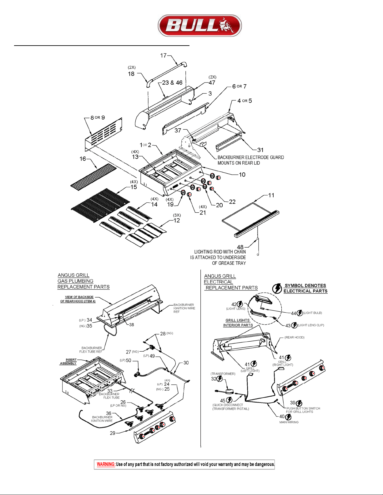
ANGUS GRILL REPLACEMENT PARTS LIST
MODEL #47628 LP & #47629 NG (
Any item with an * next to it requires a serial number)
NUMBER USED ON
ILLUSTRATION, PG 33
BULL
PART NO.
DESCRIPTION
* SERIAL NUMBER REQUIRED
QTY
WARRANTY
PERIOD (YEARS)
1 47003 INSERT ASSEMBLY (2016 & OLDER MODELS) 1 Lifetime
2 47023 INSERT ASSEMBLY (2017 & NEWER MODELS) 1 Lifetime
3 47019 LID - FRONT 1 1
4 47002 LID - REAR (2016 & OLDER MODELS) 1 1
5 47021 LID - REAR (2017 & NEWER MODELS) 1 1
6 47012 COVER - REAR LID (2016 & OLDER MODELS) 1 1
7 47022 COVER - REAR LID (2017 & NEWER MODELS) 1 1
8 47008 BACK PANEL (2016 & OLDER MODELS) 1 1
9 47024 BACK PANEL (2017 & NEWER MODELS) 1 1
10 47010 CONTROL PANEL 1 1
11 47011 GREASE TRAY 1 1
12 16670 HEAT SHIELD 3 3
13 35717 CAST STAINLESS STEEL BURNER 4 Lifetime
14 16631 VENTED FLAME TAMER 4 3
15 16517 COOKING GRATE 4 Lifetime
16 47004 WARMING RACK 1 3
17 16523 LID HANDLE CENTER BAR 1 3
18 16522 LID HANDLE END CAP 2 3
19 16629 BEZEL - MAIN BURNER 4 1
20 16630 BEZEL - BACK BURNER 1 1
21 16613 KNOB - MAIN BURNER 4 1
22 16617 KNOB - BACK BURNER 1 1
23 16690 LARGE TEMPERATURE GAUGE 1 1
24 16525 GAS VALVE - MAIN BURNER (LIQUID PROPANE MODEL ONLY) 4 1
25 16524 GAS VALVE-MAIN BURNER (NATURAL GAS MODEL ONLY) 4 1
26 16526 GAS VALVE - BACK BURNER (LIQUID PROPANE OR NATURAL GAS MODEL) 1 1
27 16507 REGULATOR (NATURAL GAS MODEL ONLY) 1 1
28 16599 REGULATOR ADAPTER (NATURAL GAS MODEL ONLY) 2 1
29 47005 *MANIFOLD 1 3
30 47006 *STAINLESS FLEX TUBE 1 1
31 47007 *INFRARED ROTISSERIE BURNER 1 1
32 16534 *TRANSFORMER 1 1
33 47009 *BACK BURNER STAINLESS FLEX TUBE 1 1
34 16527 *BACK BURNER ORIFICE (LIQUID PROPANE MODEL ONLY) 1 1
35 16528 *BACK BURNER ORIFICE (NATURAL GAS MODEL ONLY) 1 1
36 16512 BACK BURNER IGNITION WIRE 1 1
37 16511 ELECTRODE 1 1
38 16569 BACK BURNER ORIFICE AIR INLET GUARD 1 1
39 16612 *PUSH BUTTON LIGHT SWITCH 1 1
40 16638 *QUICK-DISCONNECT LIGHT WIRE HARNESS 1 1
41 16627 *LIGHT HOUSING 2 1
42 16530 *LIGHT LENS 2 1
43 16529 *LIGHT LENS CLIP 2 1
44 16532 LIGHT BULB 2 N/A
45 16634 QUICK DISCONNECT TRANSFORMER PIGTAIL 1 1
46 16692 LARGE TEMPERATURE GAUGE BEZEL 1 1
47 16635 RUBBER BUMPER FOR LID 2 1
48 97022 LIGHTING ROD WITH CHAIN 1 1
49 16598 FLARE TO FLARE UNION (LIQUID PROPANE MODEL ONLY) 1 1
50 16589 LP HOSE AND REGULATOR (LIQUID PROPANE MODEL ONLY) 1 1
31
ANGUS GRILL REPLACEMENT PARTS LIST ILLUSTRATION
32
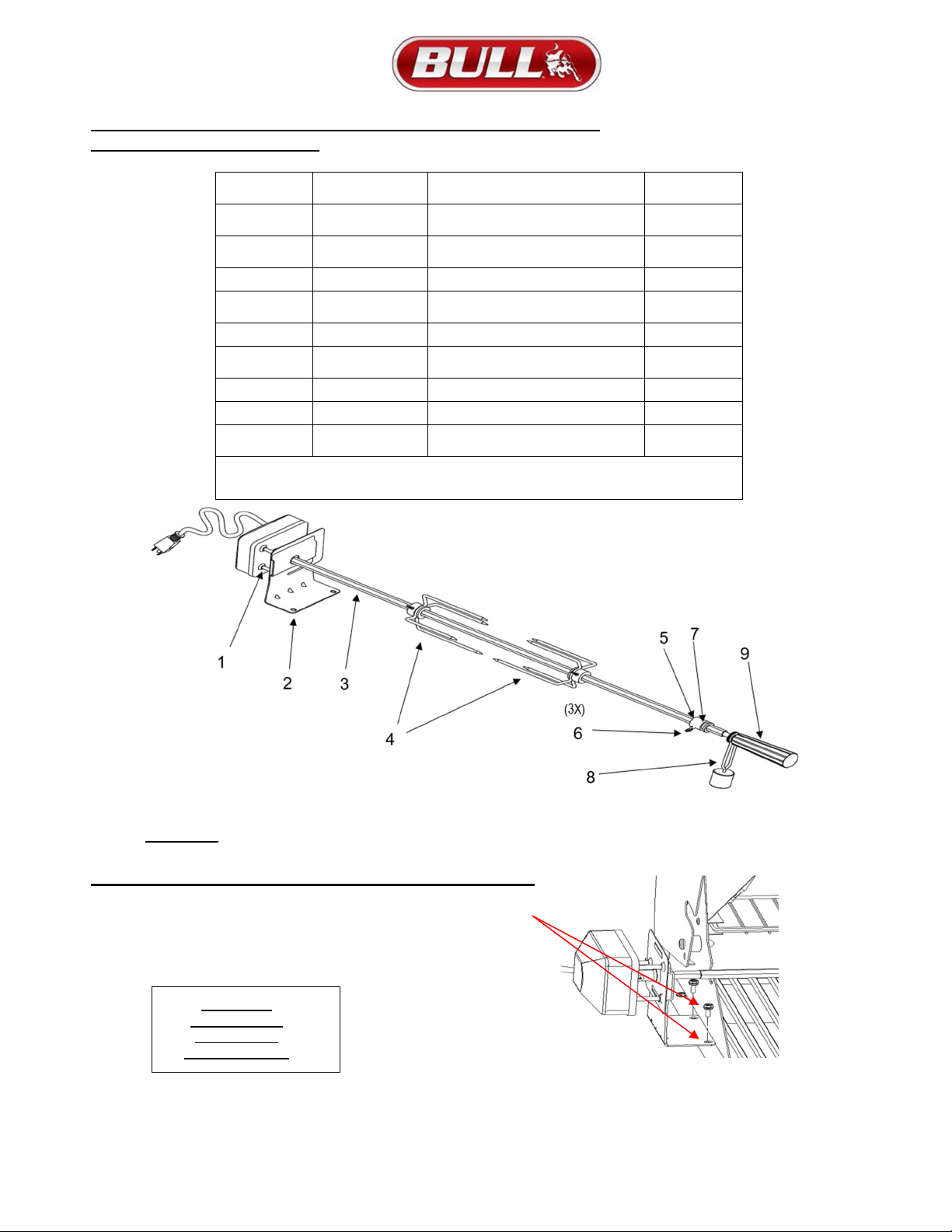
ROTISSERIE SYSTEM PARTS LIST WITH EXPLODED ILLUSTRATION
AND INSTALL INSTRUCTIONS
REF
#
PARTS
#
DESCRIPTION QTY
1 16552
110 VAC MOTOR
W/SWITCH
1
2 16554
MOTOR MOUNT
BRACKET
1
3 16551 30" GRILL SPIT ROD 1
4 16553
LARGE 4-PRONG SPIT
FORK
2
5 16591 SHAFT COLLAR 1
6 16587
1/4-20 X 1/2
THUMBSCREW
3
7 16675 KEY WASHER 1
8 16586 COUNTER-BALANCE 1
9 16585
BLACK PHENOLIC
HANDLE
1
WARRANTY IS 1 YEAR FOR ALL PARTS
WARNING: Use of any part that is not factory authorized will void your warranty and maybe dangerous.
ROTISSERIE MOTOR MOUNTING BRACKET INSTALLATION
The Rotisserie Motor slides on to the bracket and is bolted to the
flange on the outside of the grill. Use the first 2 mounting holes
as shown to align the motor with slot on the grill lid that the spit
goes through. Bracket can be installed on either side of the unit.
REFER TO
PAGE 17 FOR
OPERATING
INSTRUCTIONS

33
Warranty Policy
LIMITEDWARRANTYONBULLOUTDOORPRODUCTS,INC.,PRODUCTS
THISLIMITEDWARRANTYGIVESYOUSPECIFICLEGALRIGHTS.YOUMAYALSOHAVEOTHERRIGHTS,
WHICHVARYFROMSTATETOSTATE.
THISLIMITEDWARRANTYCANALSOBEFOUNDONOURWEBSITEAT:
https://www.bullbbq.com/support-warranty(UnitedStatesCustomers);
https://www.bullbbq.eu/en/warrantyform.htm(InternationalCustomers)
ANDINTHEOWNER’S/INSTALLATIONMANUALTHATWEPROVIDEWITHOURPRODUCT.
THISLIMITEDWARRANTYISSUBJECTTOTHEEXCLUSIONS,CONDITIONSANDLIMITATIONSSET
FORTHBELOW.
ANYIMPLIEDWARRANTIESIMPOSEDBYLAW,INCLUDINGWITHOUTLIMITATIONTHEIMPLIED
WARRANTIESOFMRECHANTABILITYANDFITNESSFORAPARTICULARPURPOSE,ARELIMITEDIN
DURATIONTOTHEDURATIONOFTHISEXPRESSLIMITEDWARRANTY.SOMESTATESDONOT
ALLOWLIMITATIONSONHOWLONGANIMPLIEDWARRANTYLASTS,SOTHEABOVELIMITATION
MAYNOTAPPLYTOYOU.
WHOMAYUSETHISWARRANTY?
BULL OUTDOOR PRODUCTS, INC. located at address 1011 East Pine St. Lodi, CA. 95240
("we") extend this limited warranty only to the consumer who originally purchased the product ("you") at the
original site of delivery or installation. It does not extend to any subsequent owner or other transferee of the
product. It does not apply to products installed in any rental, commercial or non-residential application.
Examples of excluded applications include, but are not limited to day care centers, schools, bed and breakfast
centers, churches, private clubs, fire stations, club houses, common areas in multi-family dwellings,
restaurants, hotels, nursing homes, food service locations and institutional food service locations.
WHATDOESTHISWARRANTYCOVER?
This limited warranty covers defects in materials and workmanship of the product and product components
identified below for the Warranty Periods defined below.
WHATISTHEPERIODOFCOVERAGE?
This limited warranty starts on the date of your purchase and lasts for the time period or time periods
specified above (the "WarrantyPeriod"). The Warranty Period is not extended if we repair or replace the
product. We may change the availability of this limited warranty at our discretion, but any changes will not
be retroactive.

34
Warranty Policy (Continued)
GrillWarrantyPeriods
The following parts are covered for oneyear on all our current gas grill models:
The lid, control panel, grease tray, bezels, knobs, temperature gauge, valves, regulator, flex tubes, rotisserie
burner, transformer, and all components of the lighting system.
The following parts are covered for threeyears on all our current gas grill models:
The manifold, handle end caps, flame tamers, heat shields, and warming rack.
The following parts are covered for lifetime on all our current gas grill models:
Insert assembly and the grates.
The warranty period for the grill burners vary by type:
Cast stainless steel burners - lifetime,
Welded burners – 5years, and
Porcelain coated burners – 3years.
The warranty period for the charcoal grill is oneyear on all parts, except for the insert assembly, which is
covered for 5years.
The Bel Air grill included a one‐year warranty on all parts.
ComponentWarrantyPeriods
All of the parts for our components/grill carts/refrigerators/kegerators/drawers/doors are covered for one
year with these exceptions:
Power Burner
o The insert/grates are lifetime covered parts.
o The manifold/burner are covered for 3years.
Searing Station/Slide in Double Sideburner
o The grates are covered for lifetime,
o the insert for 5years, and
o the manifold for 3years.
Single Sideburner
o The grates are covered for 5years and
o the burner for 3years.
Sidekick
o The burner is covered for 3years.
PizzaOvens/Islands/FireFeaturesWarrantyPeriods
All of the parts and construction materials are covered for oneyear.
Grill Accessories and Grill Covers do not include a warranty period.

35
Warranty Policy (Continued)
WHATDOESTHISWARRANTYNOTCOVER?
This limited warranty does not cover any damage due to: (a) transportation; (b) storage; (c) improper
installation or use; (d) use on improper fuel/gas supply; (e) failure to follow the product instructions or
to perform any preventive maintenance; (f) modifications; (g) unauthorized repair; (h) normal wear and
tear; or (i) external causes such as accidents, abuse, or other actions or events beyond our reasonable
control.
WHATAREYOURREMEDIESUNDERTHISWARRANTY?
With respect to any defective product claim made during the Warranty Period, we will, in our sole
discretion, either: repair or replace such product (or the defective part) free of charge or (b) refund the
purchase price of such product. We will not pay for shipping charges for repaired or replacement parts, or
for any labor or labor related charges. We will not pay for any accessory products or ancillary products
purchased by you for use in connection with the product.
HOWDOYOUOBTAINWARRANTYSERVICE?
To obtain warranty service, you must submit a warranty claim online through the Bullbq.com website
during the Warranty Period. Warranty claims will not be accepted via email, fax or phone.
LIMITATIONOFLIABILITY
THEREMEDIESDESCRIBEDABOVEAREYOURSOLEANDEXCLUSIVEREMEDIESANDOURENTIRE
LIABILITY FOR ANY
BREACH OF THIS LIMITED WARRANTY. OUR LIABILITY SHALL UNDER NO
CIRCUMSTANCESEXCEEDTHEACTUALAMOUNTPAIDBYYOUFORTHEDEFECTIVEPRODUCT,NOR
SHALL WE UNDER ANY CIRCUMSTANCES BE LIABLE FOR ANY CONSEQUENTIAL, INCIDENTAL,
SPECIALORPUNITIVEDAMAGESORLOSSES,WHETHERDIRECTORINDIRECT.
SOME STATES DO NOT ALLOW THE
EXCLUSION OR LIMITATION OF INCIDENTAL OR
CONSEQUENTIALDAMAGES,SOTHEABOVELIMITATIONOREXCLUSIONMAYNOTAPPLYTOYOU.
Revised 10-15-2020 APR