Loading ...
Loading ...
Loading ...
Use 1//, (3 mm) drill bit and drill 4 pilot holes as shown.
NOTE: Make the drill holes on the thin area of the slot.
A. Drill pilot hole
A
3.Install the 4 - .45 cm x 1.3 cm mounting screws in
pilot holes. Leave about 1/4"(6.4 mm) space between
screw heads and cabinet to slide range hood into place.
\\\\_\\\\ _- 1/4"
(6.4 mm)
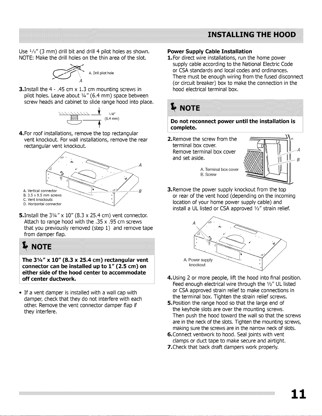
4.For roof installations, remove the top rectangular
vent knockout. For wall installations, remove the rear
rectangular vent knockout.
A. Vertical connector
B. 3.5 x 9.5 mm screws
C. Vent knockouts
D. Horizontal connector
5.Install the 31/4" x 10" (8.3 x 25.4 cm) vent connector.
Attach to range hood with the .35 x .95 cm screws
that you previously removed (step 1) and remove tape
from damper flap.
Power Supply Cable Installation
1.For direct wire installations, run the home power
supply cable according to the National Electric Code
or CSAstandards and local codes and ordinances.
There must be enough wiring from the fused disconnect
(or circuit breaker) box to make the connection in the
hood electrical terminal box.
Do not reconnect power until the installation is
complete.
2. Remove the screw from the
terminal box cover.
Remove terminal box cover
and set aside.
A. Terminal box cover
B. Screw
3.Remove the power supply knockout from the top
or rear of the vent hood (depending on the incoming
location of your home power supply cable) and
install a UL listed or CSAapproved 1/2"strain relief.
A
The 31/4" x 10" (8.3 x 25.4 cm) rectangular vent
connector can be installed up to 1" (2.5 cm) on
either side of the hood center to accommodate
off center ductwork.
If a vent damper is installed with a wall cap with
damper, check that they do not interfere with each
other. Remove the vent connector damper flap if
they interfere.
A. Power supply
knockout
4.Using 2 or more people, lift the hood into final position.
Feed enough electrical wire through the 1/2"UL listed
or CSAapproved strain relief to make connections in
the terminal box. Tighten the strain relief screws.
5.Position the range hood so that the large end of
the keyhole slots are over the mounting screws.
Then push the hood toward the wall so that the screws
are in the neck of the slots. Tighten the mounting screws,
making sure the screws are in the narrow neck of slots.
6.Connect ventwork to hood. Seal joints with vent
clamps or duct tape to make secure and airtight.
7.Check that back draft dampers work properly.
Loading ...
Loading ...
Loading ...