Loading ...
Loading ...
Loading ...
ELECTRICAL WIRING
ELECTRICAL SHOCK HAZARD
Failure to turn off the main (remote) electrical dis-
connect device could result in personal injury or
death.
Before installing, modifying or servicing system,
turn OFF the main (remote) electrical disconnect
device. There may be more than one disconnect
device.
The supply voltage must be 208/230 volts (197 volt
minimum to 253 volts maximum) 60 Hz single phase.
Outdoor units are approved for use with copper
conductors only. Do not use aluminum wire.
Refer to unit rating plate for minimum circuit ampacity and
circuit protection requirements.
Grounding
Permanently ground unit in accordance with the National
Electrical Code and local codes or ordinances. Use a
copper conductor of the correct size from the grounding
lug in control box to a grounded connection in the service
panel or a properly driven and electrically grounded
ground rod.
Wiring Connections
Make all outdoor electrical supply (Line Voltage)
connections with raintight conduit and fittings. Most
codes require a disconnect switch outdoors within sight of
the unit. Consult local codes for special requirements.
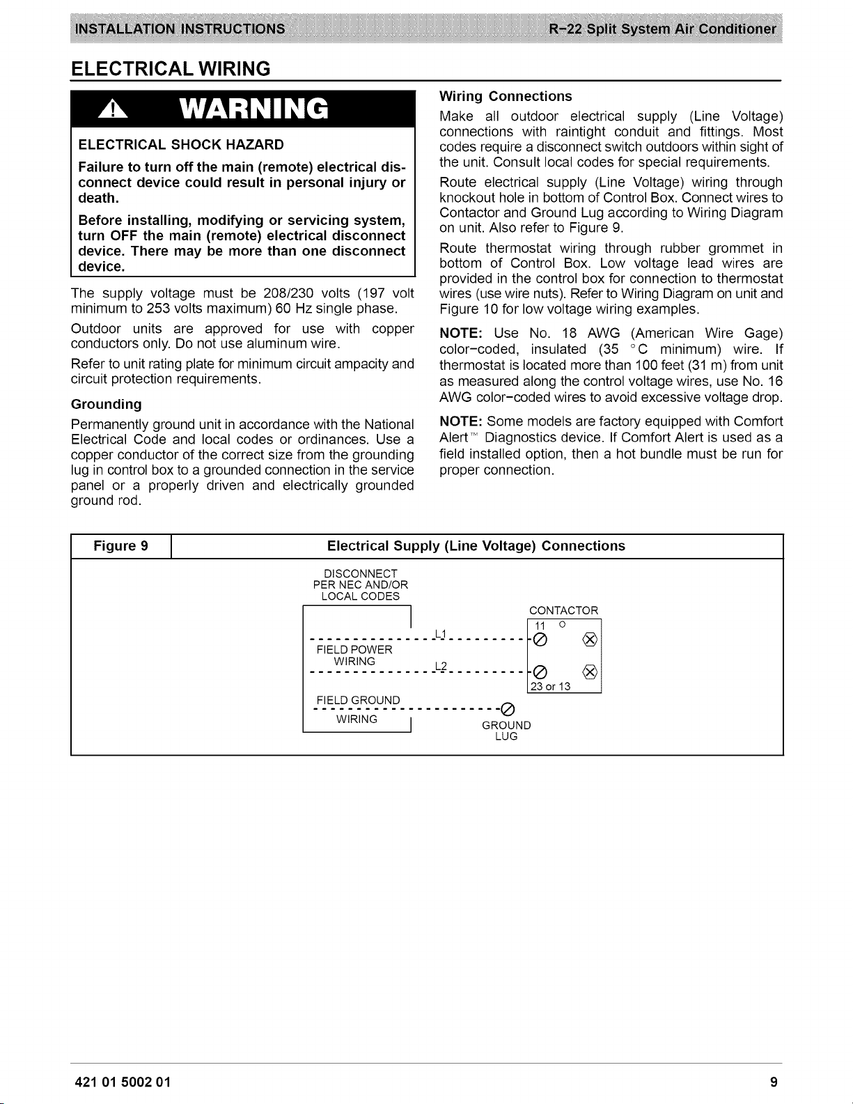
Route electrical supply (Line Voltage) wiring through
knockout hole in bottom of Control Box. Connect wires to
Contactor and Ground Lug according to Wiring Diagram
on unit. Also refer to Figure 9.
Route thermostat wiring through rubber grommet in
bottom of Control Box. Low voltage lead wires are
provided in the control box for connection to thermostat
wires (use wire nuts). Refer to Wiring Diagram on unit and
Figure 10 for low voltage wiring examples.
NOTE: Use No. 18 AWG (American Wire Gage)
color-coded, insulated (35 °C minimum) wire. If
thermostat is located more than 100 feet (31 m) from unit
as measured along the control voltage wires, use No. 16
AWG color-coded wires to avoid excessive voltage drop.
NOTE: Some models are factory equipped with Comfort
Alert TM Diagnostics device. If Comfort Alert is used as a
field installed option, then a hot bundle must be run for
proper connection.
Figure 9
1
Electrical Supply (Line Voltage) Connections
DISCONNECT
PER NEC AND/OR
LOCAL CODES
1
L1
FIELD POWER
WIRING L2
FIELD GROUND
WIRING j
CONTACTOR
Ij2_or 13 <_)
-®
GROUND
LUG
421 01 5002 01 9
Loading ...
Loading ...
Loading ...