Loading ...
Loading ...
Loading ...
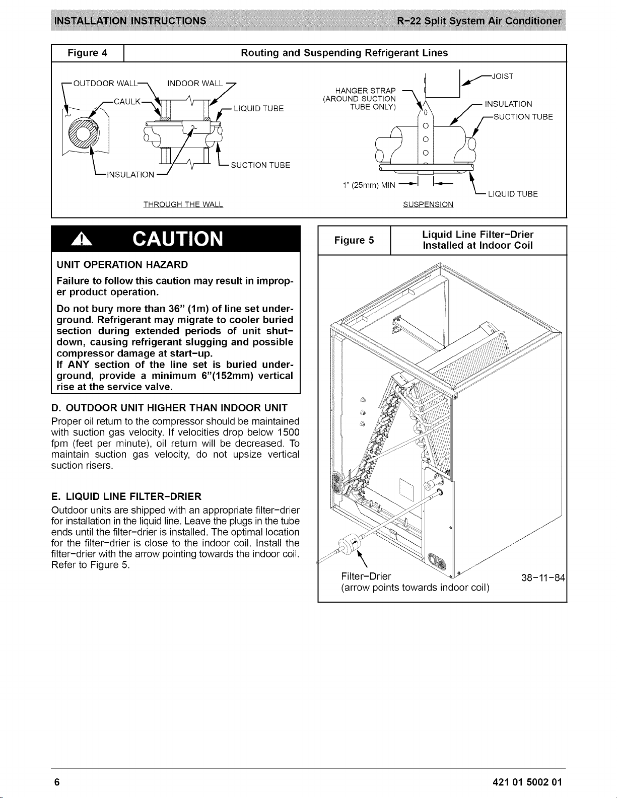
Figure4
Routing and Suspending Refrigerant Lines
O TOC w
I_"_ __r LIQUID TUBE
S CTO,
THROUGH THE WALL
HANGER STRAP
(AROUND SUCTION X.. --
TUBE ONLY) _.J
h
r JOIST
S;'cTA:'oO2T
1" (25mm) MIN -_D,-I I_
LIQUID TUBE
SUSPENSION
UNIT OPERATION HAZARD
Failure to follow this caution may result in improp-
er product operation.
Do not bury more than 36" (lm) of line set under-
ground. Refrigerant may migrate to cooler buried
section during extended periods of unit shut-
down, causing refrigerant slugging and possible
compressor damage at start-up.
If ANY section of the line set is buried under-
ground, provide a minimum 6"(152mm) vertical
rise at the service valve.
D. OUTDOOR UNIT HIGHER THAN INDOOR UNIT
Proper oil return to the compressor should be maintained
with suction gas velocity. If velocities drop below 1500
fpm (feet per minute), oil return will be decreased. To
maintain suction gas velocity, do not upsize vertical
suction risers.
E. LIQUID LINE FILTER-DRIER
Outdoor units are shipped with an appropriate filter-drier
for installation in the liquid line. Leave the plugs in the tube
ends until the filter-drier is installed. The optimal location
for the filter-drier is close to the indoor coil. Install the
filter-drier with the arrow pointing towards the indoor coil.
Refer to Figure 5.
Liquid Line Filter-Drier
Figure 5 Installed at Indoor Coil
Filter-Drier
(arrow points towards indoor coil)
38-11-84
6 421 01 5002 01
Loading ...
Loading ...
Loading ...