
Email: Sales@ACOPower.com
Call: (626) 575-7722
Web:www.acopower.com
Address:4120 Valley Blvd, Walnut CA 91789, USA
User Manual
Solar Panel Kits
1 2 3 4 5 6 7 8 9
10 11 12 13 14 15 16
Please read the instruction manual carefully before attempting to carry out any
installation or wiring. Contact Technical support for any questions concerning the
installation.
WARNING: Indicates a potentially dangerous condition. Use extreme caution when
performing this task.
CAUTION: Indicates a critical procedure for safe and proper operation.
NOTE: Indicates a procedure or function that is important to the safe and proper
operation.
Installation and wiring compliance
Installation and wiring must comply with the local and National Electrical Codes and must be
done by a certified electrician. Please follow these four steps:
Preventing fire and explosion hazards
Working with electronic/electrical equipment may produce arcs or sparks. Thus, such
equipment should not be used in areas where there are flammable materials or gases
requiring ignition protected equipment. These areas may include spaces containing
gasoline-powered machinery, fuel tanks, and battery compartments.
Precautions when working with batteries
1. Read all of the instructions and cautions in the manual before beginning the installation.
2. It is HIGHLY recommended to install a charge controller in order to charge your
batteries. It is dangerous for unregulated panels to be connected to battery banks.
3. Make sure all wire connections are secured; loose connections may cause sparks.
4. Wear appropriate clothing and safety gear including protective eyewear when
performing any electrical installation.
• Batteries contain very corrosive diluted sulfuric acid as electrolyte. Precautions should
be taken to prevent contact with skin, eyes, or clothing.
• Batteries generate hydrogen and oxygen during charging, resulting in the evolution of an
explosive gas mixture.
Safety Instructions
Please save these instructions
Email: Sales@ACOPower.com Call: (626) 575-7722 Web:www.acopower.com
Address:4120 Valley Blvd, Walnut CA 91789, USA
1 2 3 4 5 6 7 8 9
10 11 12 13 14 15 16

Precautions when working with solar panels
With the incidence of sunlight or other light sources on all solar panels, a voltage
appears at the output terminals of the solar panel turning it into a source of electricity.
To avoid a shock hazard, make sure the solar panel is covered with an opaque (dark)
material such as paper or cloth during the installation. Do not make contact with the
terminals when the panel is exposed to sunlight or any other light source.
Routine maintenance
• Care should be taken to ventilate the battery area and follow the battery manufac
turer’s recommendations. Never smoke or allow a spark or flame near the batteries.
• Use caution to reduce the risk of dropping a metal tool on the battery. It could spark
or short circuit the battery or other electrical parts and could cause an explosion.
• Remove metal items such as rings, bracelets, and watches when working with
batteries. The batteries can produce a short circuit current high enough to weld a
ring or similar object to the metal, causing a severe burn.
• If you need to remove a battery, always remove the ground terminal from the battery
first. Make sure that all the accessories are off so that you do not cause a spark.
• Only use properly insulated tools when making battery connections.
• Inspect the solar panels and make sure the surfaces are free from dust, dirt, and
other debris; clean with a wet cloth or glass cleaner if necessary.
• Check to make sure all structural components, mechanical fasteners, and electrical
connections are secure, clean, and corrosion-free.
• Check and maintain the battery electrolyte levels at regular intervals as per the
battery manufacturer’s recommendations if flooded wet cell lead acid batteries are
used.
• Check and replace damaged components if necessary.
Email: Sales@ACOPower.com Call: (626) 575-7722 Web:www.acopower.com
Address:4120 Valley Blvd, Walnut CA 91789, USA
1 2 3 4 5 6 7 8 9
10 11 12 13 14 15 16

Table of Contents
General Information ....................................................................................................... 4
100W Solar Panel Specifiation....................................................................................... 4
Z-Bracket Mounting ........................................................................................................5
Making Brackets to panel Frame ....................................................................................5
Adjustable Angle triangle bracket ...................................................................................7
Mounting brackets ..........................................................................................................7
Battery to charge controller ............................................................................................9
Extending the output wires of the solar panel ...............................................................10
Solar Panel to charge controller ....................................................................................11
Multiple panels/strings in parallel ..................................................................................13
Two adjacent panels in parallel (12V systems) 200W ..................................................13
Three adjacent panels in parallel (12V systems) 300W ...............................................14
Four panels in parallel (12V systems) 400W ................................................................15
Five adjacent panels in parallel (12V systems)500W ...................................................16
Email: Sales@ACOPower.com Call: (626) 575-7722 Web:www.acopower.com
Address:4120 Valley Blvd, Walnut CA 91789, USA
1 2 3 4 5 6 7 8 9
10 11 12 13 14 15 16
General Information
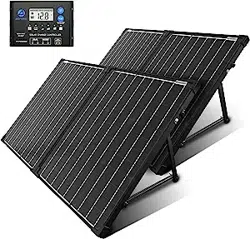
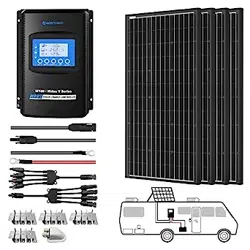
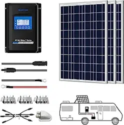
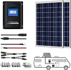
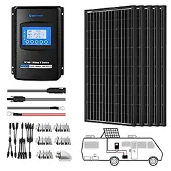
A new ACOPOWER Off-Grid Solar Kit will provide you with a clean, silent, and sustainable
way of ensuring that batteries are fully charged and capable of providing a continuous
supply of electricity. Each kit comes equipped with a high quality solar panel that features
highly efficient silicon solar cells. If you have purchased an ACOPOWER Off-Grid Solar Kit,
a MPPT Solar Charge Controller is also included in the package. This controller will serve
as a connector between the solar panel and the batteries. The solar charge
controller will ensure that the battery is charged with the appropriate amount of solar power
as per the battery manufacturer’s recommendations. The solar charge controller ‘charging
states’ are optimized to meet the requirements of most standard lead acid batteries as well
as flooded batteries. The ACOPOWER Off-Grid Solar Kit also includes a mounting system
comprised of sturdy aluminum Z-Brackets as well as the nuts and bolts required to flat
mount a solar panel onto a roof or any other flat surface.
This manual will provide you with instructions on how to assemble the various components
of an ACOPOWER Off-Grid Solar Kit. Please refer to the separate ACOPOWER Solar
Charge Controller Manual for detailed information about the installation, operation, and
programming of the solar charge controller.
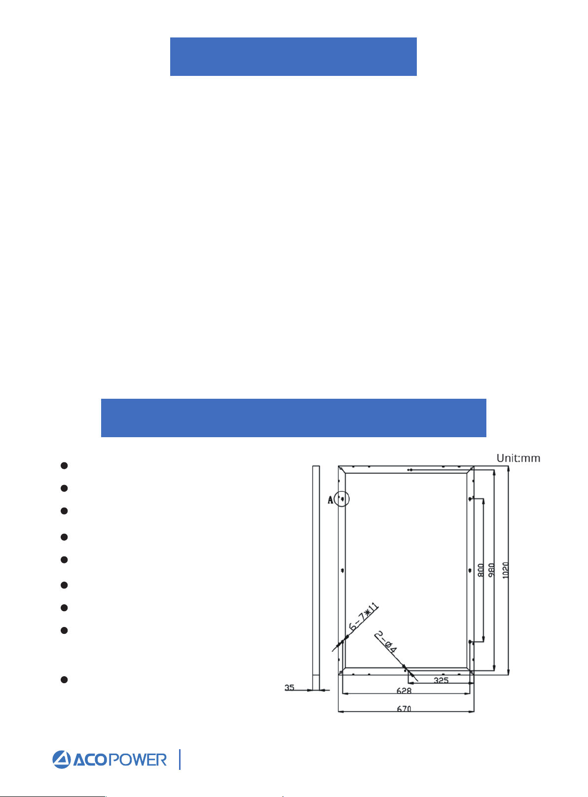
100W Solar Panel Specification
Peak Power (Pmax):100W
Peak Circuit Voltage(Voc):22V
Max Power Voltage(Vmp):17.48V
Short Circuit Current(Isc): 6.14A
Max Power Current(Imp):5.71A
Wind resistance:2400pa
Weight:20.94 lb
Dimension: 40.2*26.4*1.4Inch
(1020*670*35mm)
Application Class:Class A
Email: Sales@ACOPower.com Call: (626) 575-7722 Web:www.acopower.com
Address:4120 Valley Blvd, Walnut CA 91789, USA
1 2 3 4 5 6 7 8 9
10 11 12 13 14 15 16
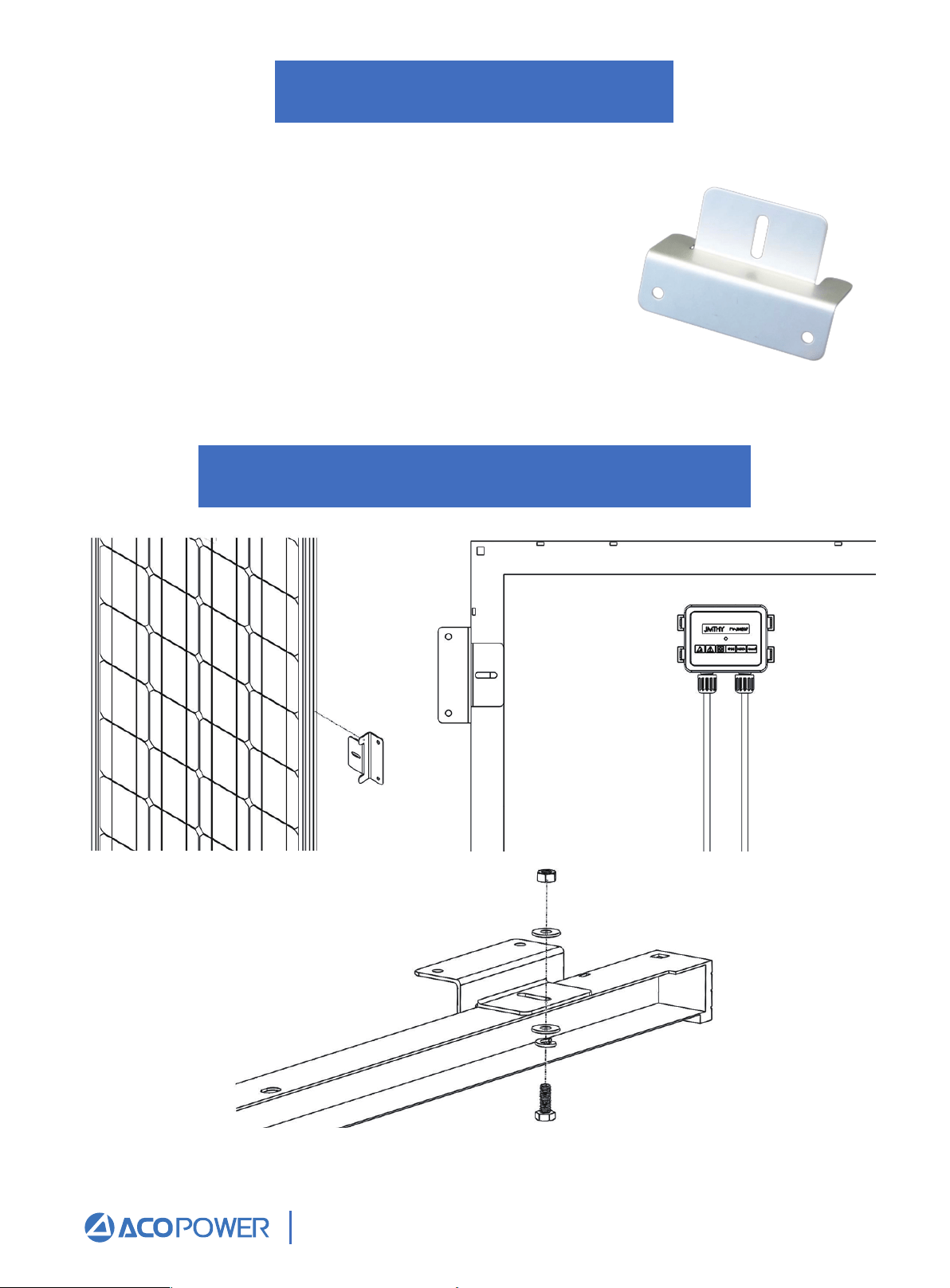
Z-Bracket Mounting
Making Brackets to Panel Frame
ACOPOWER Z-Bracket Mounting
The ACOPOWER Z-Bracket Mount System is designed to
support the installation of single panel units, generally in
off-grid installations. These units are ideal for installation
on RV roofs and noninhabited dwellings such as sheds or
garages. It is also suited as attachment to a user made
structure such as a wooden frame. The system comes
complete with all fasteners to secure the system to the
installation surface. This system makes the installation of
small solar systems easy, affordable and quick.
Repeat for each Z-Bracket in the set at each corner.
Email: Sales@ACOPower.com Call: (626) 575-7722 Web:www.acopower.com
Address:4120 Valley Blvd, Walnut CA 91789, USA
1 2 3 4 5 6 7 8 9
10 11 12 13 14 15 16
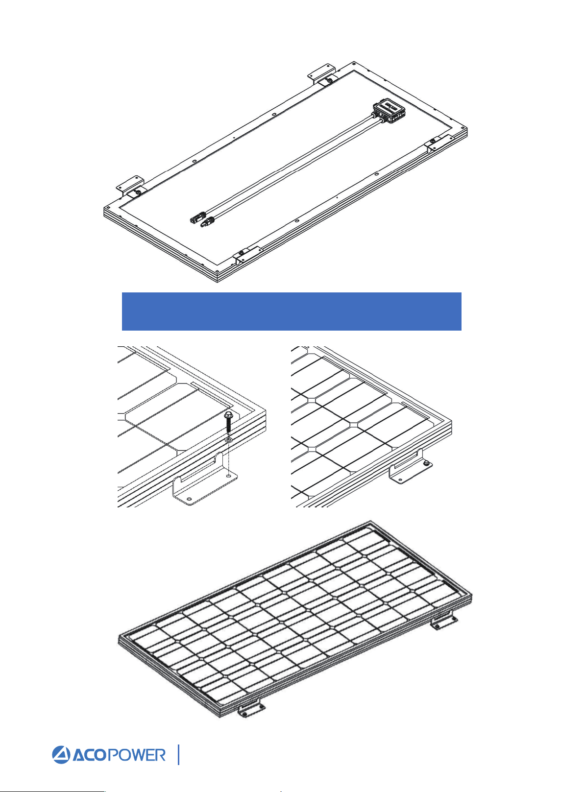
Making Brackets to Panel Frame
Email: Sales@ACOPower.com Call: (626) 575-7722 Web:www.acopower.com
Address:4120 Valley Blvd, Walnut CA 91789, USA
1 2 3 4 5 6 7 8 9
10 11 12 13 14 15 16
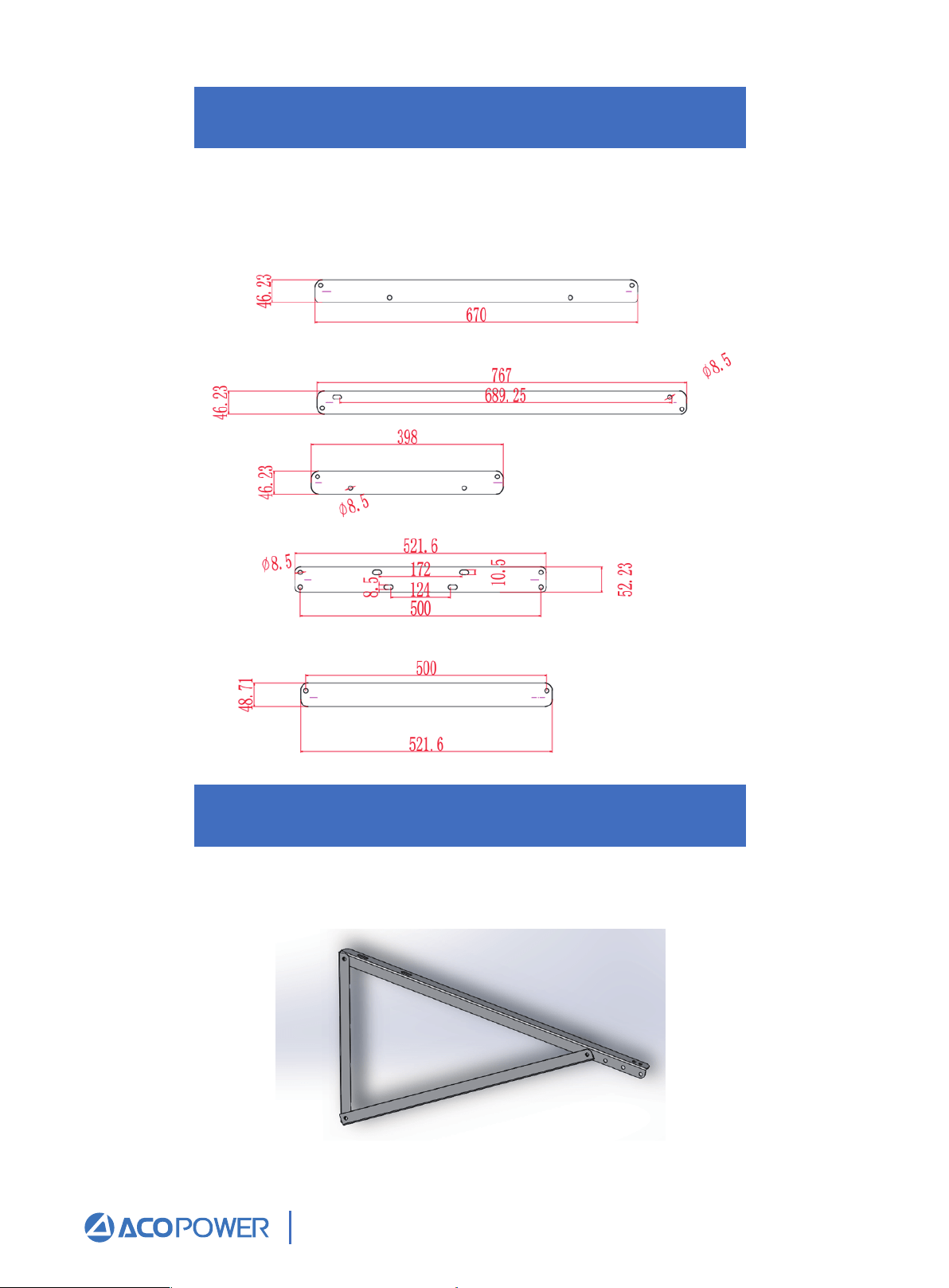
Adjustable Angle Triangle Bracket
Mounting Brackets
If you need to install in other places, such as pole, walls, trees, etc., it is recommended that
you choose the triangle bracket with adjustable Angle, and the Angle adjustment range is
30°35°40°45°.This bracket is sold separately, not as a supporting product.
Assemble left and right triangle supports
Extend the triangle bracket and tighten the fixing bolts.
Email: Sales@ACOPower.com Call: (626) 575-7722 Web:www.acopower.com
Address:4120 Valley Blvd, Walnut CA 91789, USA
1 2 3 4 5 6 7 8 9
10 11 12 13 14 15 16
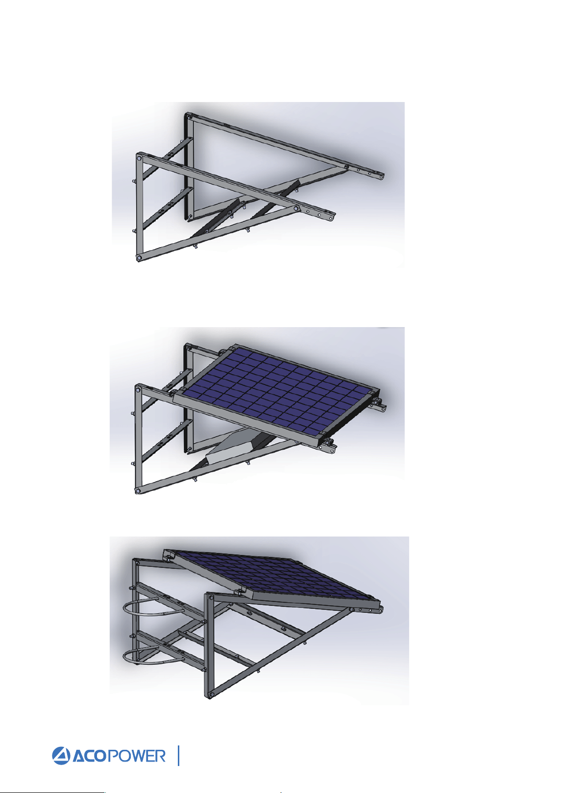
Install back support angle
All angle steel fixing frames are fixed with M8 * 50 bolts.
Install solar panel fixing blocks and install photovoltaic panels.
Place the photovoltaic panel on the support, and then fasten the pressing block to fix the
photovoltaic panel.
U-bolt mounting
Email: Sales@ACOPower.com Call: (626) 575-7722 Web:www.acopower.com
Address:4120 Valley Blvd, Walnut CA 91789, USA
1 2 3 4 5 6 7 8 9
10 11 12 13 14 15 16
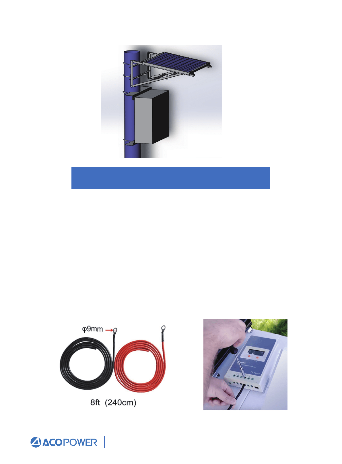
Battery to Charge Controller
Overall rendering
The battery(s) must first be connected to the charge controller before proceeding to any
other connections. Most MPPT Controllers have automatic battery voltage detection, and
the controller must detect what voltage level it will be charging at.
Use a screwdriver to rotate and unscrew the "o" port of the MPPT controller, so that the
positive red line of the battery line is connected to the positive pole of the MPPT charging
controller, and the negative black line of the battery line is connected to the negative pole
of the MPPT charging controller.Put the metal wafer lasso of the red line of the positive
electrode of the battery on the positive electrode of the battery, and the metal wafer lasso
of the black line of the negative electrode of the battery on the negative electrode of the
battery.At this point, the connection between the battery and the MPPT charging controller
is completed, and the screen of the MPPT charging controller will display the battery
voltage information.
Email: Sales@ACOPower.com Call: (626) 575-7722 Web:www.acopower.com
Address:4120 Valley Blvd, Walnut CA 91789, USA
1 2 3 4 5 6 7 8 9
10 11 12 13 14 15 16
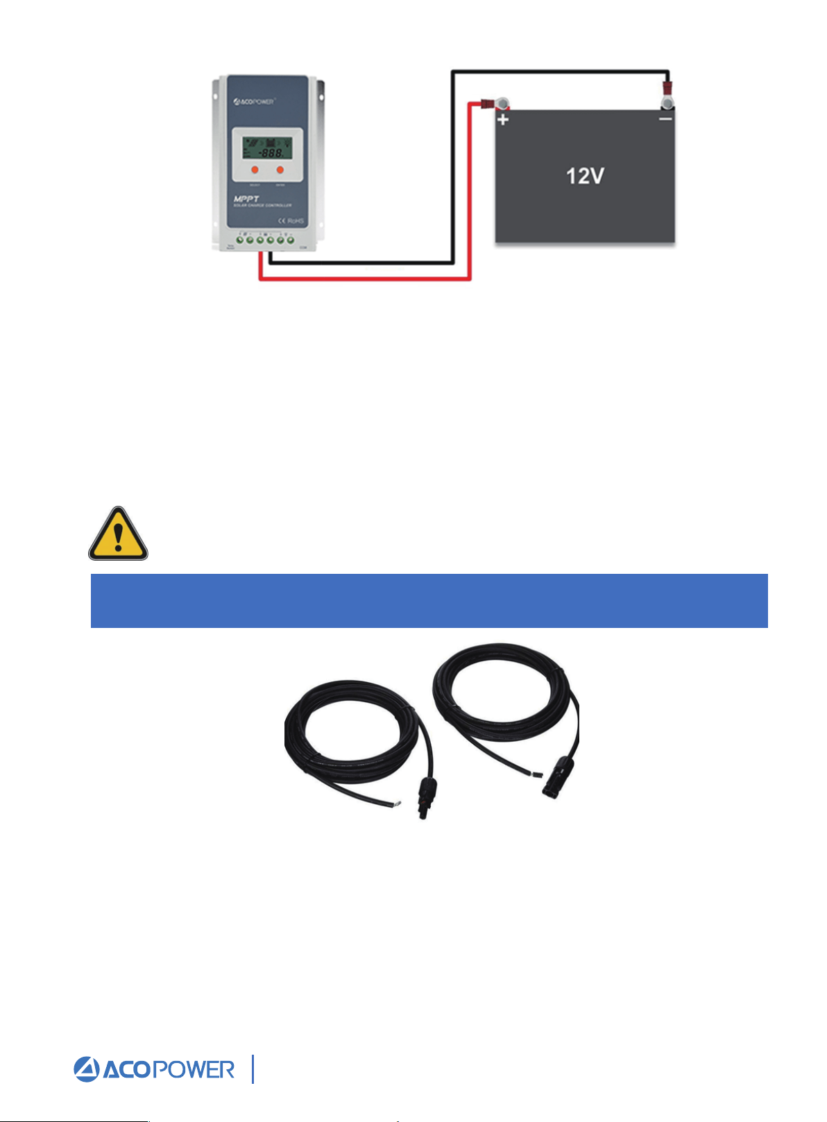
Extending the output wires of the solar panel
Figure 1 Charge controller connected to a 12V battery
Fig.2. MC4 Adapter Kit
Before starting the connection, keep in mind the following:
• The charge controller should be as close as possible to the batteries. This helps
keep line loss to a minimum level.
• Remember to always use the recommended gauge size based on the PV system
and charge controller.
The battery must first be wired to the charge controller before the solar panel is
connected to the charge controller.
Email: Sales@ACOPower.com Call: (626) 575-7722 Web:www.acopower.com
Address:4120 Valley Blvd, Walnut CA 91789, USA
1 2 3 4 5 6 7 8 9
10 11 12 13 14 15 16
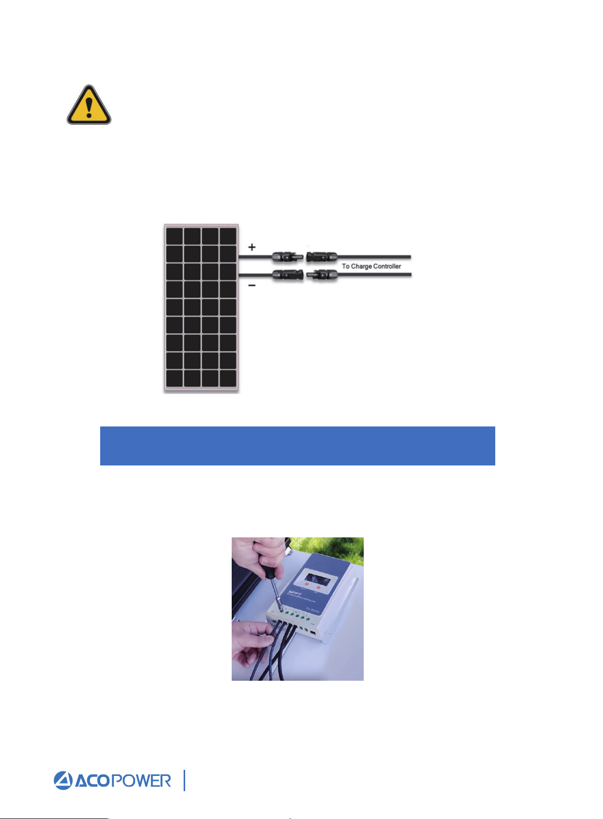
Solar Panel to Charge Controller
The adapter kits have different lengths, and the basic size is No. 12 AWG. It is suitable for
parallel connection of 100W / 200W / 300W / 400W / 500W solar panels.
The typical connection for 12V panels using a MPPT Controller is a parallel
connection. This connection increases the current, but keeps the voltage level the
same. When placing multiple panels in parallel, it is necessary to size the wire.
Please refer to Figure 3. This figure shows the extending of the output wires of the
ACOPOWER-100W Solar Panel using the adapter kit. The polarity labeled on the panel’s
leads should be the only ones to follow. When adapting the leads, mark the positive (+)
cable; doing so will avoid reverse polarity when connecting the panel(s) to the controller.
Figure 3 Solar panel and adapter kit
Use a screwdriver to connect the bare end of the red positive pole line of the MC4
extension cord to PV+ "o" of the MPPT charging controller, and the bare end of the black
negative pole line of the MC4 extension cord to pv-" o "of the MPPT charging controller.
Email: Sales@ACOPower.com Call: (626) 575-7722 Web:www.acopower.com
Address:4120 Valley Blvd, Walnut CA 91789, USA
1 2 3 4 5 6 7 8 9
10
11 12 13 14 15 16
MC4
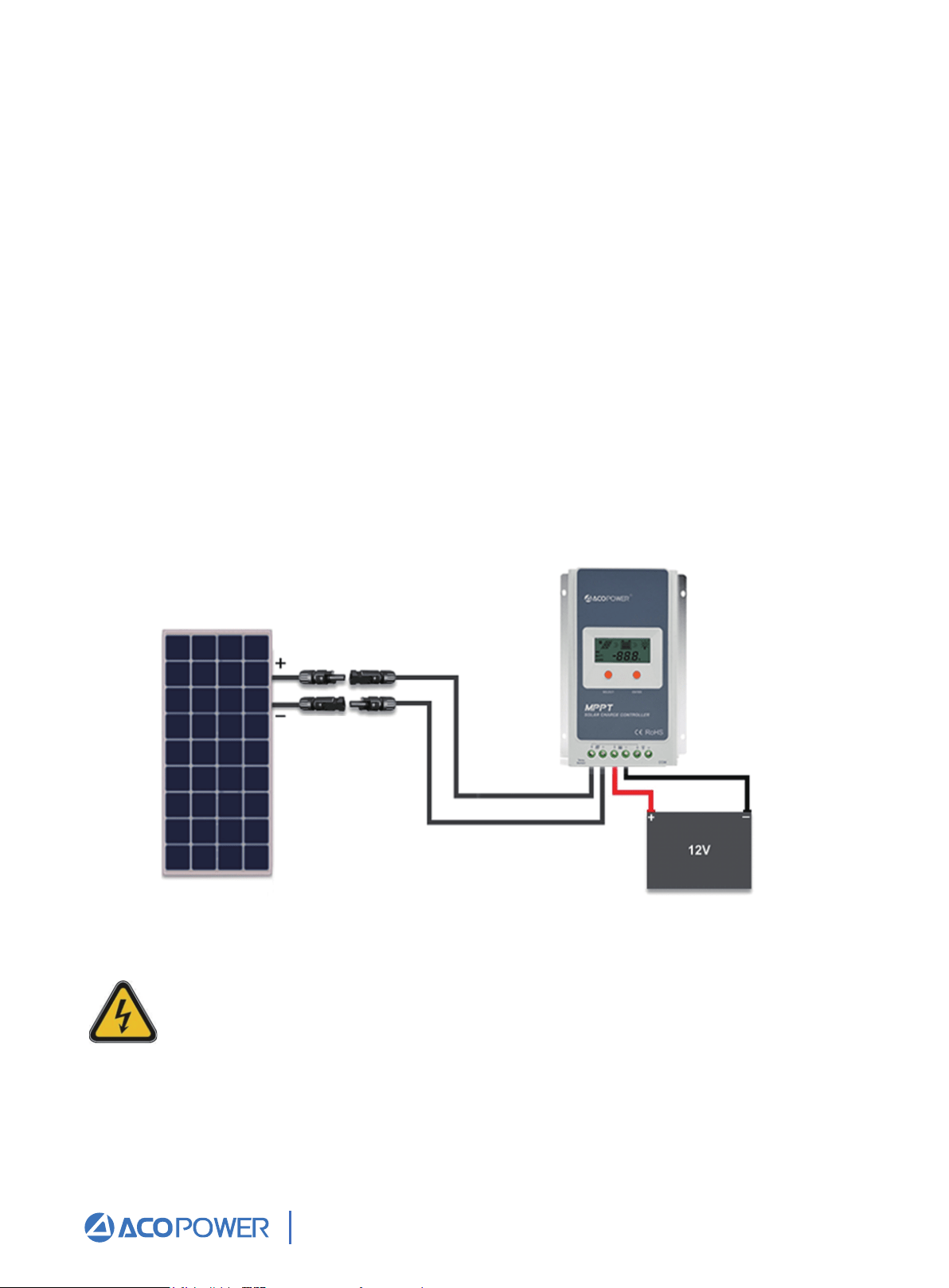
Once the battery is connected to the charge controller and the panel(s) are positioned
and mounted in the desired location, we are ready to connect the panel(s) to the charge
controller.
Panels should be mounted in a place that is free from shading by neighboring obstacles
such as vents, air-conditioners, TV antennas, etc.
Please refer to Figure 4 when completing the following connections:
First, mate the “Male” MC4 Connector from the solar panel that has the negative (−)
label with the “Female” MC4 Connector of your adapter kit as shown in Figure 4.
Then connect the bare stranded portion of the cable to the negative (−) solar input
terminal on the charge controller.
Next, mate the “Female” MC4 connector from the panel that has the positive (+)
label with the “Male” MC4 connector of your adapter kit as show in Figure 4.
Connect the bare stranded portion of the adapter cable to the positive (+) solar
input terminal on the charge controller. Remove the protective cloth. If there is
enough sunlight present, the controller’s solar indicator/icon on the LCD display
should show that it is now charging your battery(s).
1.
2.
3.
Figure 4 Completed 12V off-grid system
The panel MUST be covered with a dark cloth to prevent the solar cells
from producing energy; this will prevent and reduce shock hazard, which
can be life threatening.
Email: Sales@ACOPower.com Call: (626) 575-7722 Web:www.acopower.com
Address:4120 Valley Blvd, Walnut CA 91789, USA
1 2 3 4 5 6 7 8 9
10 11
12 13 14 15 16
MC4
Multiple Panels/Strings in Parallel
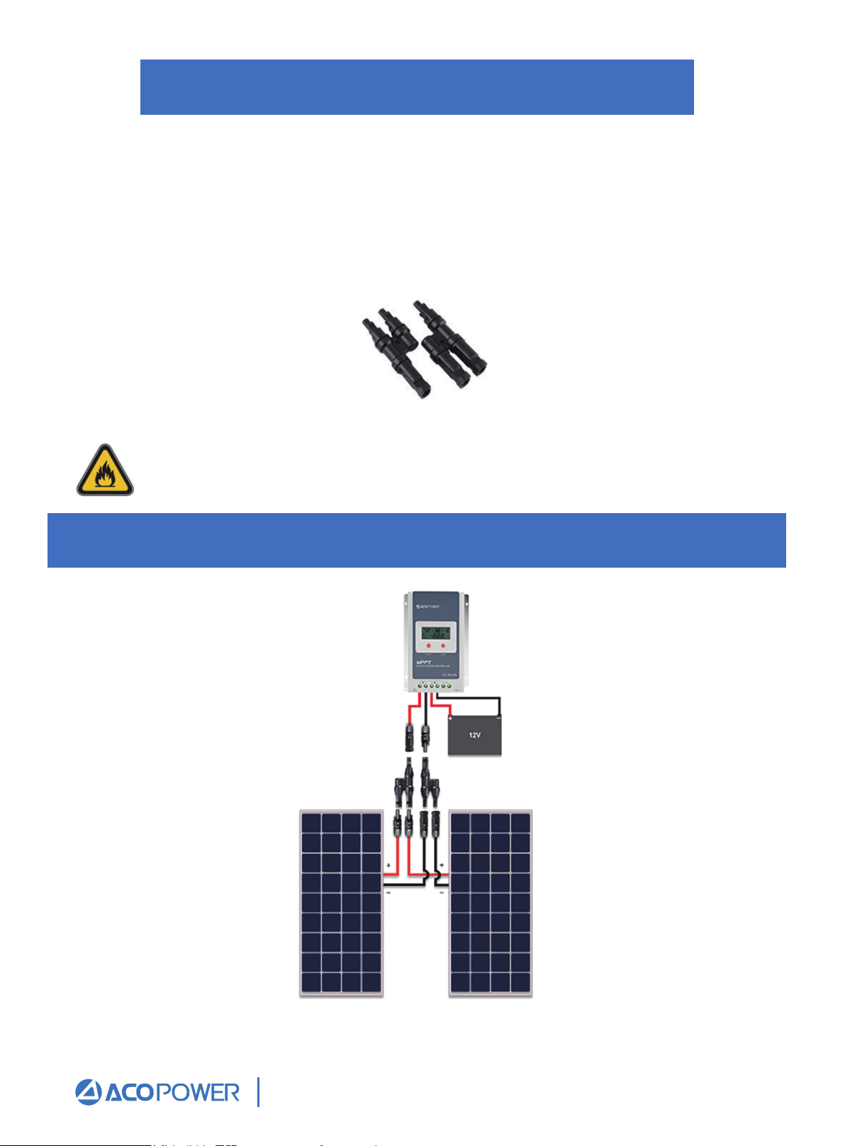
Two adjacent panels in parallel (12V systems) 200W
A parallel connection is achieved by joining all of the positive (+) and negative (-) nodes
together. When placing panels in parallel, it is recommended that the voltage levels are
within specification. In other words, the Vmp (maximum power voltage) of the panels must
all be within 10% of each other. Typically, connecting panels in parallel is achieved
through using identical panels. A simple way to place panels/strings in parallel is by using
a branch connector, shown in Figure 5.
Figure 5 Pair of MC4Y- Branch Connectors
Remember to always use the recommended gauge size based on the total array
current. Sizing the cable incorrectly may result in melting wires and/or fire.
Figure 6 Two 100W Panels in parallel
Email: Sales@ACOPower.com Call: (626) 575-7722 Web:www.acopower.com
Address:4120 Valley Blvd, Walnut CA 91789, USA
1 2 3 4 5 6 7 8 9
10 11 12
13 14 15 16
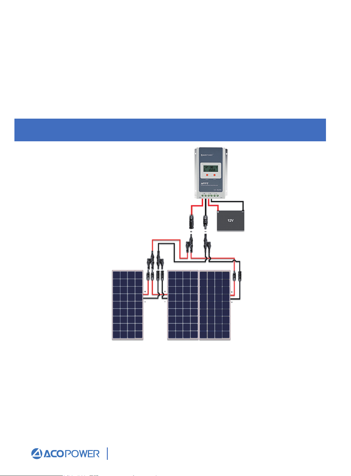
Three adjacent panels in parallel (12V systems) 300W
Figure 7 Three 100W Panels in parallel
One of the most basic solar configurations involves wiring two solar panels in parallel.
This parallel configuration will increase the current output while the output voltage
remains the same. Fig.6 above shows the arrangement for connecting two solar panels in
parallel with one pair of MC4 Y-Branch Connectors. This arrangement is applicable if two
solar panels will be mounted adjacent to one another. This connection requires one (1)
pair of MC4 Branch Connectors. When the panels are mounted at different locations- that
is, separated by a distance, the panels must be extended with MC4 Extension Cables
(sold separately).
Three solar panels is the maximum amount of panels that can be connected in parallel if they
are adjacent to one another, without using extra cabling. Fig. 7 above shows the arrangement
for connecting three solar panels in parallel. Remember that this arrangement is applicable if
the three solar panels are to be mounted adjacent to one another. This connection requires
two (2) pairs of MC4 Y-Branch Connectors. When one or multiple panels are mounted at
different locations- that is, separated by a distance, the panels need to be extended with MC4
Extension Cables (sold separately).
Email: Sales@ACOPower.com Call: (626) 575-7722 Web:www.acopower.com
Address:4120 Valley Blvd, Walnut CA 91789, USA
1 2 3 4 5 6 7 8 9
10 11 12 13
14 15 16
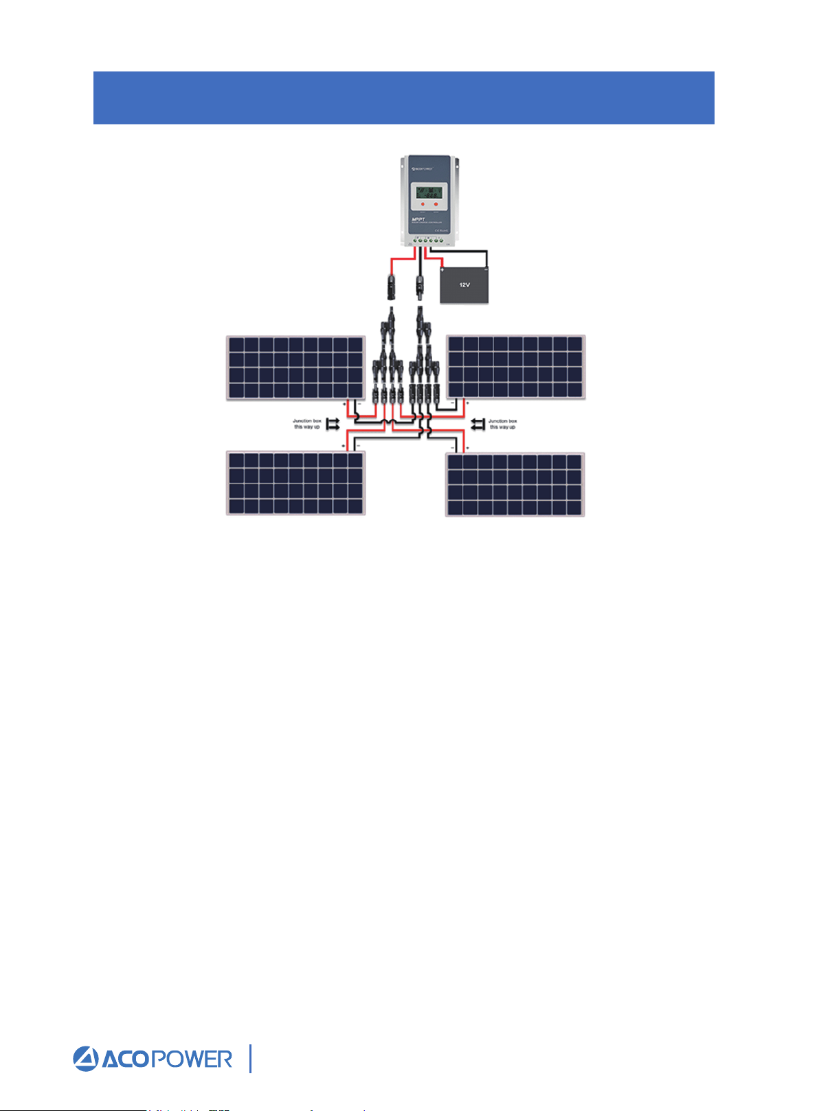
Four panels in parallel (12V systems) 400W
Figure 8 Four 100W Panels in parallel
Fig. 8 shows the arrangement for connecting four solar panels in parallel. This arrangement is
applicable if the solar panels are to be mounted in a 2x2 configuration as shown above.
Please note that the positioning of the junction boxes must be followed for the cables to reach
the MC4 Branch Connectors. This connection requires three (3) pairs of MC4 Y -Branch
Connectors. When one or multiple panels are mounted at different locations- that is, separated
by a distance, the panels must be extended with MC4 Extension Cables (sold separately).
Email: Sales@ACOPower.com Call: (626) 575-7722 Web:www.acopower.com
Address:4120 Valley Blvd, Walnut CA 91789, USA
1 2 3 4 5 6 7 8 9
10 11 12 13 14
15 16
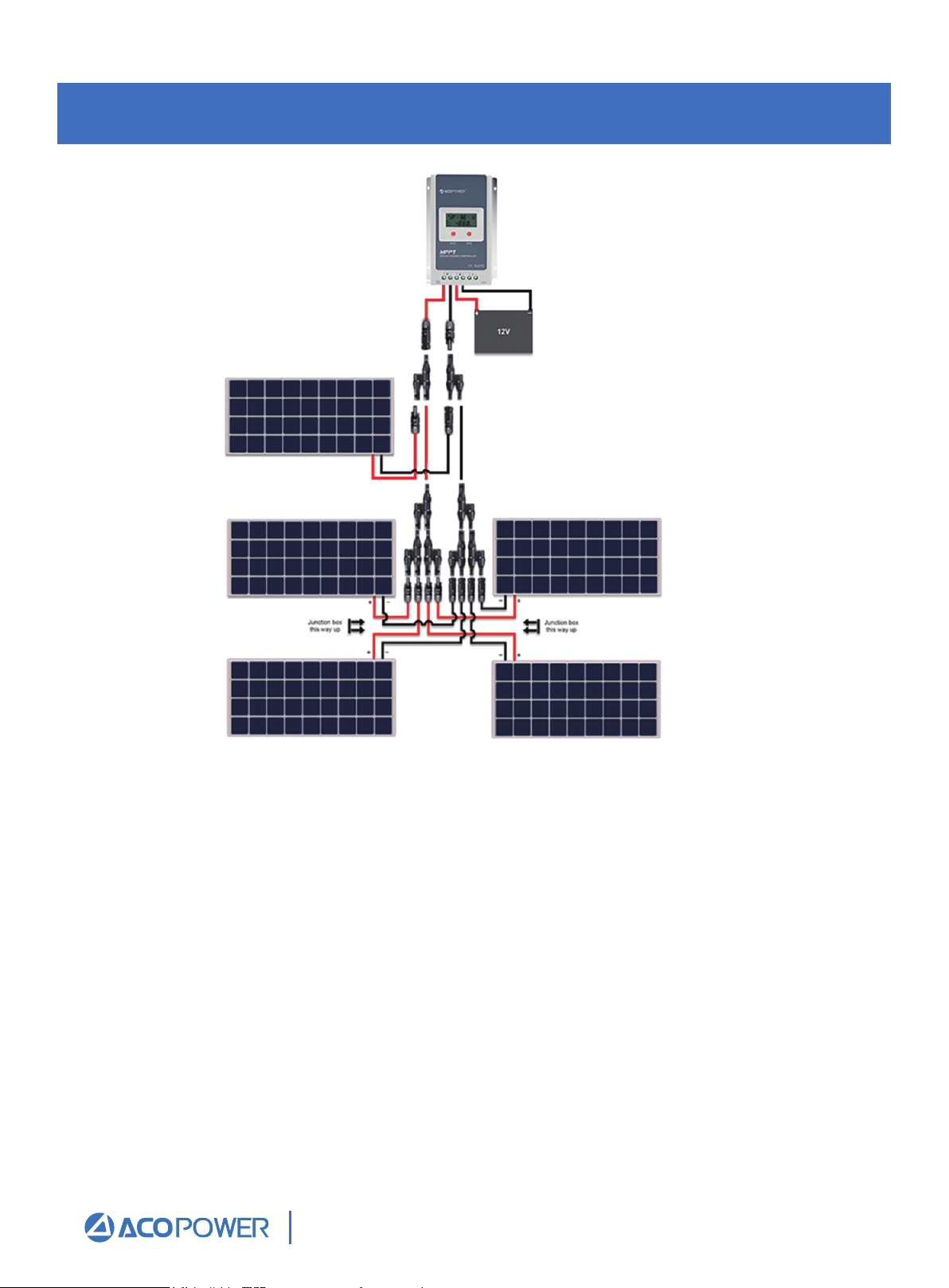
Five adjacent panels in parallel (12V systems)500W
Five solar panels is the maximum amount of panels that can be connected in parallel if they
are adjacent to one another, without using extra cabling. Fig. 9 above shows the arrangement
for connecting five solar panels in parallel. Remember that this arrangement is applicable if
the five solar panels are to be mounted adjacent to one another. This connection requires four
(4) pairs of MC4 Y- Branch Connectors. When one or multiple panels are mounted at
different locations- that is, separated by a distance, the panels need to be extended with MC4
Extension Cables (sold separately).
Figure 9 Five 100W Panels in parallel
Email: Sales@ACOPower.com Call: (626) 575-7722 Web:www.acopower.com
Address:4120 Valley Blvd, Walnut CA 91789, USA
1 2 3 4 5 6 7 8 9
10 11 12 13 14 15
16