Operating Instructions and Parts Manual
1236 Lathe
Model: E-1236VS
JET
®
427 New Sanford Road
LaVergne, Tennessee 37086
www.jettools.com
Ph.: 855-336-4032
M-E-1236VS
REV E1 02/2019
Copyright © 2017 JET
This .pdf document is bookmarked

2
1236 Lathe
1.0 WARRANTY AND SERVICE
JET
®
warrants every product it sells against manufacturers’ defects. If one of our tools needs service or repair, please
contact Technical Service by calling 1-855-336-4032, 8AM to 5PM CST, Monday through Friday.
WARRANTY PERIOD
The general warranty lasts for the time period specified in the literature included with your product or on the official JET
branded website, jettools.com.
WHO IS COVERED?
This warranty covers only the initial purchaser of the product from the date of delivery.
WHAT IS COVERED?
This warranty covers any defects in workmanship or materials subject to the limitations stated below. This warranty does not
cover failures due directly or indirectly to misuse, abuse, negligence or accidents, normal wear-and-tear, improper repair,
alterations or lack of maintenance.
HOW TO GET TECHNICAL SUPPORT
Please contact Technical Service by calling 1-855-336-4032. Please note that you will be asked to provide proof of initial
purchase when calling. If a product requires further inspection, the Technical Service representative will explain and assist
with any additional action needed. JET has Authorized Service Centers located throughout the United States. For the name
of an Authorized Service Center in your area call 1-855-336-4032 or use the Service Center Locator on the JET website.

3
E-1236VS
MORE INFORMATION
JET
®
is constantly adding new products. For complete, up-to-date product information, check with your local distributor or
visit the JET website, jettools.com.
HOW STATE LAW APPLIES
This warranty gives you specific legal rights, subject to applicable state law.
LIMITATIONS ON THIS WARRANTY
JET LIMITS ALL IMPLIED WARRANTIES TO THE PERIOD OF THE LIMITED WARRANTY FOR EACH PRODUCT.
EXCEPT AS STATED HEREIN, ANY IMPLIED WARRANTIES OF MERCHANTABILITY AND FITNESS FOR A PARTICULAR
PURPOSE ARE EXCLUDED. SOME STATES DO NOT ALLOW LIMITATIONS ON HOW LONG AN IMPLIED WARRANTY
LASTS, SO THE ABOVE LIMITATION MAY NOT APPLY TO YOU.
JET SHALL IN NO EVENT BE LIABLE FOR DEATH, INJURIES TO PERSONS OR PROPERTY, OR FOR INCIDENTAL,
CONTINGENT, SPECIAL, OR CONSEQUENTIAL DAMAGES ARISING FROM THE USE OF OUR PRODUCTS. SOME
STATES DO NOT ALLOW THE EXCLUSION OR LIMITATION OF INCIDENTAL OR CONSEQUENTIAL DAMAGES, SO
THE ABOVE LIMITATION OR EXCLUSION MAY NOT APPLY TO YOU.
JET sells through distributors only. The specifications listed in JET printed materials and on official JET website are given as
general information and are not binding. JET reserves the right to effect at any time, without prior notice, those alterations
to parts, fittings, and accessory equipment which they may deem necessary for any reason whatsoever. JET
®
branded
products are not sold in Canada by JPW Industries, Inc.
NOTE: JET is a division of JPW Industries, Inc. References in this document to JET also apply to JPW Industries, Inc., or
any of its successors in interest to the JET brand.

4
1236 Lathe
2.0 TABLE OF CONTENTS
1.0 WARRANTY AND SERVICE ........................................................................................................................................2
2.0 TABLE OF CONTENTS ................................................................................................................................................4
3.0 SAFETY PRECAUTIONS ............................................................................................................................................5
4.0 INTRODUCTION ..........................................................................................................................................................7
5.0 SPECIFICATION AND ACCESSORIES ...................................................................................................................... 7
5.1 GENERAL LAYOUT OF LATHE ..............................................................................................................................7
5.2 DIMENSIONS ...........................................................................................................................................................8
5.3 FOUNDATION PLAN................................................................................................................................................8
5.4 SPECIFICATIONS ....................................................................................................................................................9
5.5 STANDARD ACCESSORIES ................................................................................................................................10
5.6 OPTIONAL ACCESSORIES ..................................................................................................................................10
6.0 INSTALLATION ...........................................................................................................................................................10
6.1 LEVELING THE LATHE .........................................................................................................................................10
6.2 COMPLETING INSTALLATION .............................................................................................................................11
6.3 CHUCK PREPARATION ........................................................................................................................................11
6.4 BREAK-IN PERIOD ................................................................................................................................................12
6.5 CHUCK KEY BRACKET ........................................................................................................................................12
7.0 MAINTENANCE/LUBRICATION ................................................................................................................................12
7.1 BALL OILER LOCATIONS .....................................................................................................................................13
7.2 COOLANT PREPARATION ...................................................................................................................................14
8.0 ELECTRICAL CONNECTIONS .................................................................................................................................15
9.0 BASIC CONTROLS ....................................................................................................................................................15
10.0 OPERATION .............................................................................................................................................................17
10.1 TOOL SETUP ........................................................................................................................................................18
10.2 SPINDLE SPEED .................................................................................................................................................18
10.3 FEED AND THREAD SELECTION .....................................................................................................................18
10.4 THREAD CUTTING ..............................................................................................................................................18
11.0 ADJUSTMENTS ........................................................................................................................................................19
11.1 CHUCK JAW REVERSAL ....................................................................................................................................19
11.2 GIB ADJUSTMENTS ............................................................................................................................................19
11.3 TAILSTOCK ADJUSTMENTS ..............................................................................................................................20
11.4 GAP SECTION ......................................................................................................................................................20
11.5 ALIGNING TAILSTOCK TO HEADSTOCK .........................................................................................................20
11.6 CROSS SLIDE NUT ADJUSTMENT ...................................................................................................................21
11.7 SHEAR PIN REPLACEMENT ..............................................................................................................................21
11.8 STEADY REST ADJUSTMENT ...........................................................................................................................21
11.9 FOLLOW REST ADJUSTMENT ..........................................................................................................................21
12.0 RECOMMENDED CUTTING SPEED OF LATHE ..................................................................................................22
13.0 REPLACEMENT PARTS ..........................................................................................................................................22
14.0 WIRING DIAGRAMS ................................................................................................................................................68
15.0 SCHEDULE OF ELECTRICAL EQUIPMENT .........................................................................................................70

5
E-1236VS
3.0 SAFETY PRECAUTIONS
1. Read and understand the entire owner’s manual before attempting assembly or operation.
2. Read and understand the warnings posted on the machine and in this manual. Failure to comply with all of these
warnings may cause serious injury.
3. Replace the warning labels if they become obscured or removed.
4. This lathe is designed and intended for use by properly trained and experienced personnel only. If you are not familiar
with the proper and safe operation of a lathe, do not use until proper training and knowledge have been obtained.
5. Do not use this lathe for other than its intended use. If used for other purposes, JET
®
, disclaims any real or implied
warranty and holds itself harmless from any injury that may result from that use.
6. Always wear approved safety glasses/face shields while using this lathe. Everyday eyeglasses only have impact
resistant lenses; they are not safety glasses.
7. Before operating this lathe, remove tie, rings, watches and other jewelry, and roll sleeves up past the elbows. Remove
all loose clothing and confine long hair. Non-slip footwear or anti-skid floor strips are recommended. Do not wear
gloves.
8. Wear ear protectors (plugs or muffs) during extended periods of operation.
9. Do not operate this machine while tired or under the influence of drugs, alcohol or any medication.
10. Make certain the switch is in the OFF position before connecting the machine to the power supply.
11. Make certain the machine is properly grounded.
12. Make all machine adjustments or maintenance with the machine unplugged from the power source.
13. Remove adjusting keys and wrenches. Form a habit of checking to see that keys and adjusting wrenches are
removed from the machine before turning it on.
14. Keep safety guards in place at all times when the machine is in use. If removed for maintenance purposes, use
extreme caution and replace the guards immediately after maintenance is complete.
15. Check damaged parts. Before further use of the machine, a guard or other part that is damaged should be carefully
checked to determine that it will operate properly and perform its intended function. Check for alignment of moving
parts, binding of moving parts, breakage of parts, mounting and any other conditions that may affect its operation. A
guard or other part that is damaged should be properly repaired or replaced.
16. Do not use power tools in damp/wet locations or other dangerous environments. Do not expose them to rain. Keep
work area well lighted. Provide for adequate space surrounding work area and non-glare, overhead lighting.
17. Keep the floor around the machine clean and free of scrap material, oil and grease.
18. Keep visitors a safe distance from the work area. Keep children away.
19. Make your workshop child proof with padlocks, master switches or by removing starter keys.
20. Give your work undivided attention. Looking around, carrying on a conversation and “horse-play” are careless acts
that can result in serious injury.
21. Maintain a balanced stance at all times so that you do not fall or lean against moving parts. Do not overreach or use
excessive force to perform any machine operation. Never force the cutting action.
22. Do not operate the lathe in flammable or explosive environments. Do not use in a damp environment or expose to
rain.
23. Use the right tool at the correct speed and feed rate. Do not force a tool or attachment to do a job for which it was not
designed. The right tool will do the job better and more safely.

6
1236 Lathe
24. Use recommended accessories; improper accessories may be hazardous.
25. Maintain tools with care. Keep cutting tools sharp and clean for the best and safest performance. Follow instructions
for lubricating and changing accessories.
26. Do not attempt to adjust or remove tools during operation. Disconnect tools before servicing; when changing
accessories, such as blades, bits, cutters, and the like.
27. Never stop a rotating chuck or workpiece with your hands.
28. Choose a low spindle speed when working unbalanced workpieces, and for threading and tapping operations.
29. Do not exceed the maximum speed of the workholding device.
30. Do not exceed the clamping capacity of the chuck.
31. Secure Work. For safety and use of both hands, use clamps or a vise to hold work when practical.
32. Workpieces longer than 3 times the chucking diameter must be supported by the tailstock or a steady rest.
33. Avoid small chuck diameters with large turning diameters.
34. Avoid short chucking lengths and small chucking contact.
35. Turn off the machine and disconnect from power before cleaning. Use a brush to remove shavings or debris — do not
use your hands.
36. Do not stand on the machine. Serious injury could occur if the machine tips over.
37. Never leave the machine running unattended. Turn the power off and do not leave the machine until moving parts
come to a complete stop.
38. Remove loose items and unnecessary work pieces from the area before starting the machine.
39. Direction of feed — feed work into a blade or cutter against the direction of rotation of the blade or cutter only.
40. Installation work and electrical wiring must be done by qualified electrician in accordance with all applicable codes
and standards.
41. Tighten all locks before operating.
42. Rotate workpiece by hand before applying power.
43. Rough out workpiece before installing on faceplate.
44. Do not mount split workpiece or one containing knot.
45. Use lowest speed when starting new workpiece.
WARNING: This product can expose you to chemicals including lead and cadmium which are known to the State of California to
cause cancer and birth defects or other reproductive harm. For more information go to http://www.p65warnings.ca.gov.
WARNING: Some dust, fumes and gases created by power sanding, sawing, grinding, drilling, welding and other construction
activities contain chemicals known to the State of California to cause cancer and birth defects or other reproductive harm. Some
examples of these chemicals are:
• lead from lead based paint
• crystalline silica from bricks, cement and other masonry products
• arsenic and chromium from chemically treated lumber
Your risk of exposure varies, depending on how often you do this type of work. To reduce your exposure to these chemicals, work
in a well-ventilated area and work with approved safety equipment, such as dust masks that are specifically designed to filter out
microscopic particles. For more information go to http://www.p65warnings.ca.gov/ and http://www.p65warnings.ca.gov/wood.
!
!
7
E-1236VS
4.0 INTRODUCTION
This manual is provided by JET
®
covering the safe operation and maintenance procedures for a JET Model E-1236VS.
This manual contains instructions on installation, safety precautions, general operating procedures, maintenance
instructions and parts breakdown. Your machine has been designed and constructed to provide years of trouble-free
operation if used in accordance with the instructions as set forth in this document.
If there are questions or comments, please contact your local supplier or JET. JET can also be reached at our web
site: www.jettools.com. Retain this manual for future reference. If the machine transfers ownership, the manual should
accompany it.
Familiarize yourself with the following safety notices used in this manual:
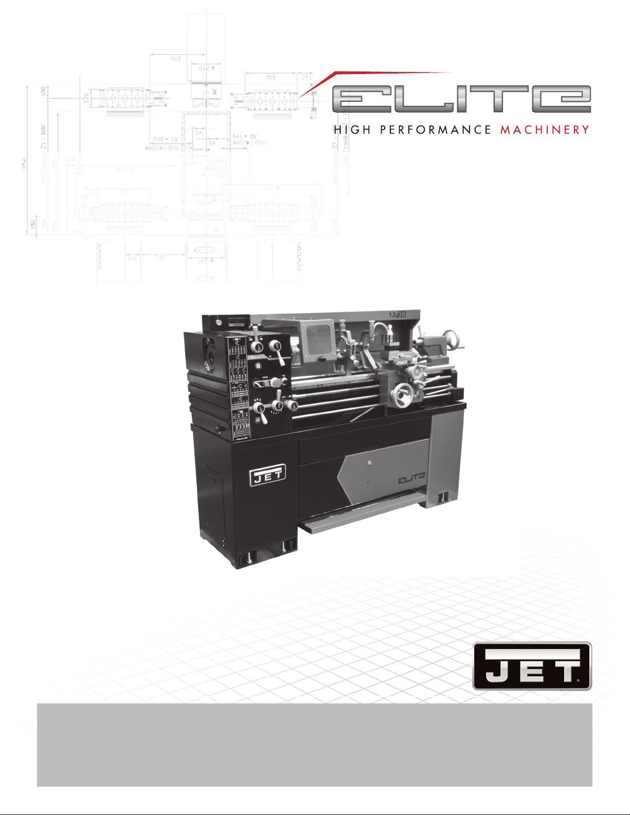
1. Headstock
2. Spindle
3. Saddle
4. Toolpost
5. Cross - slide
6. Compound - rest
(Top slide)
7. Splash Guard
8. Tailstock
9. Lead Screw
10. Feed Rod
11. Switch control rod
12. Bed
13. Stand
14. Spindle rotation lever
15. Apron
16. Footbrake
17. Cabinet (Tool box)
18. Head end stand
19. Gearbox
20. End Cover
5.0 SPECIFICATION AND ACCESSORIES
5.1 GENERAL LAYOUT OF LATHE
Fig. 1
!
This means that if precautions are not heeded, it
may result in minor injury and/or possible machine
damage.
!
This means that if precautions are not heeded, it
may result in serious injury or possibly even death.
1
20
19
18
17
16
15
14
13
12
11
10
9
8
76
5
4
3
2
8
1236 Lathe
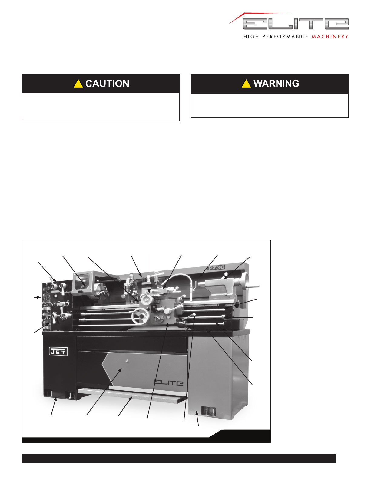
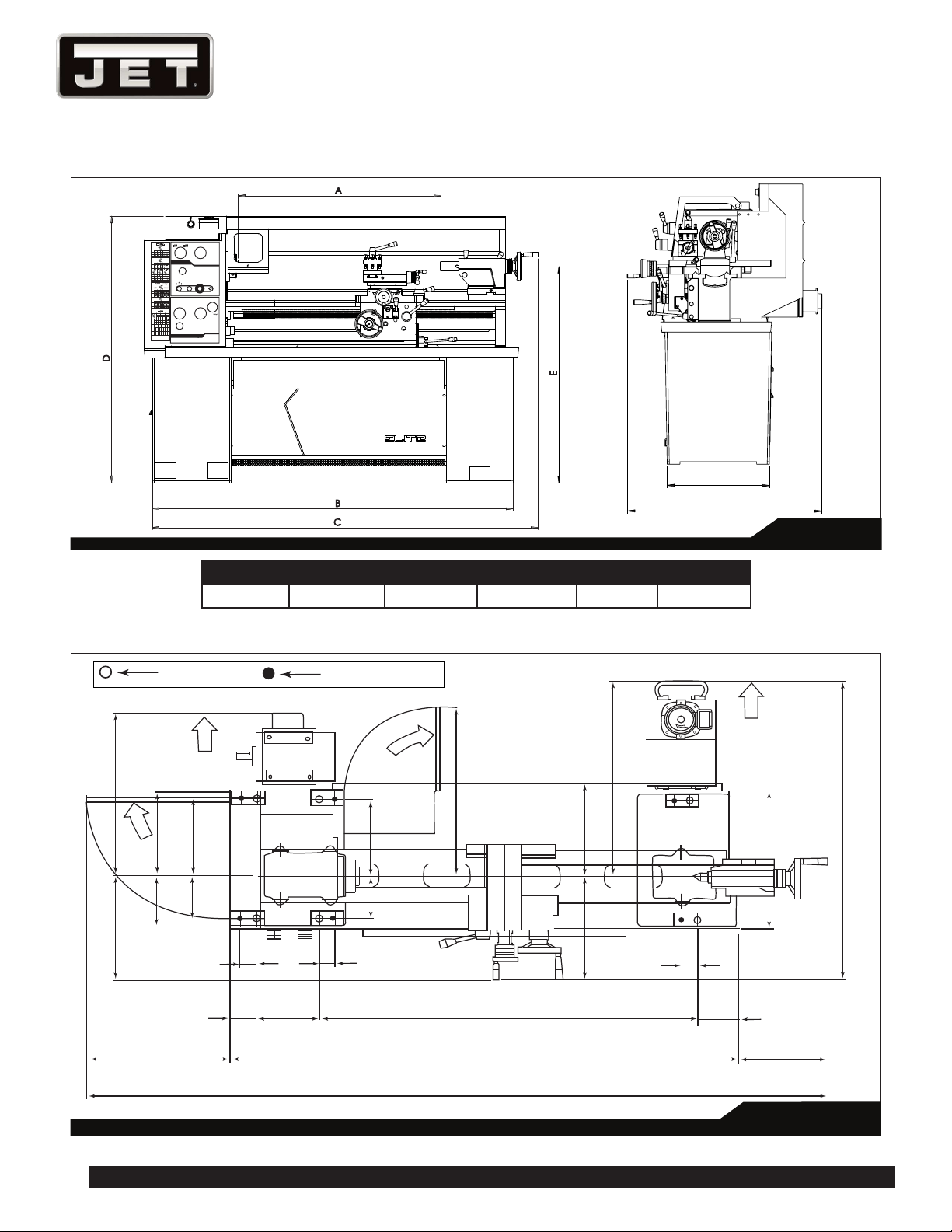
5.2 DIMENSIONS
5.3 FOUNDATION PLAN
B
C
D
A
E
H
L
RPM
TOOGLE
STOP LATHE TO
CHANGE SPEED
32 36 40 48 56
28
20 24
10 12
14
18
9
16
8
0.00280.0025 0.0023 0.0019 0.0016
0.00570.0051 0.0046 0.0038 0.0032
0.01150.0102 0.00920.0076 0.0065
0.01150.0102 0.00920.0076 0.0065
0.02300.0204 0.0184 0.0153 0.0131
0.04600.0409 0.0368 0.0307 0.0263
8
22
11
5.5
23
11.5
5.75
3 3 3
9 10 12 14
75 6
2.5 3 3.5
4.5
2.25
4
2
T.P.I
127
26
52
127
52
26
127
40
44
127
40
46
127
40
52
26
13
6.5
127
26
52
inch
127
52
26
mm
120
127
26
52
35
40
30
50
PC
MM
0.5 0.6
0.8
0.8 0.90.9
1.81.61.751.51.21.0
2.0 2.4 3.0 3.5 3.2 3.6
0.75 0.875
30
6050605030
30304040
1.8751.125 1.25
3.752.25
1.0
2.0
4.0 4.5 5.0 7.5 8.0
4.0
2.0 2.4 2.5 3.0
4.8 5.0 6.0
9.6 10 12
2.5
Leadscrew 8 TPI
B
2
3
A
C
1
4 5
Fig. 2
28.2”
19”
5/8” Hole
M12x1.75 Bolt
For electrical
box cover open
SPLASH GUARD
TRAY OUTLONE
STAND
CENTER LINE
BEDWAY
MOTOR
PUMP
TANK
For pump removal
48.4”
64.6”
93.7”
11.6”
5”
2”
2”
2”
6”
6”
7”
11”
11”
13.3”
14.2”
20”
41.9”
27.7”
24”
12”
23”
14.3”
3.4”
17.5”
For motor removal
For endcover open
For Tailstock removal
Fig. 3
Size/Type A B C D E
E-1236VS 36 in 64-1/2 in 70-1/4 in 45-1/4 in 41 in

9
E-1236VS
5.4 SPECIFICATIONS
MODEL E-1236VS
Swing over Bed 306mm 12in
Swing over Cross Slide 186mm 7-5/16in
Height of Center 150mm 6in
Distance between Centers 915mm 36in
BED
Width of Bedways 190mm 7-1/2in
Swing over Gap 445mm 17-1/2in
Length of Gap 240mm 9-1/2in
Width in front of face plate 150mm 6in
SPINDLE
Spindle nose mounting D1-4 Camlock
Spindle bore 40mm 1-9/16in
Taper of spindle bore M.T. #5
Number of spindle speeds Variable speed change
Range of spindle speeds 40-2000 R.P.M.
TOOL SLIDE
Total travel of cross slide 170mm 6-3/4in
Total travel of top slide 90mm 3-1/2in
Max. size cutting tool 13mm 1/2in
TAIL STOCK
Total travel of tailstock barrel 100mm 4in
Taper in tailstock barrel M.T. #3
Diameter of barrel 40mm 1-9/16in
THREADS
Lead screw diameter & pitch Dia. 22mm Pitch 4mm, 7/8in 8T.P.I.
Inch threads 3-24 TPI (8Nos) for metric system
2-56 TPI (34Nos) for inch system
Metric pitches 0.5-10mm (21Nos) for metric system
0.5-12mm (33Nos) for inch system
FEEDS
Feed rod diameter Dia. 19mm 3/4in
Longitudinal feeds 0.0016-0.0460in/rev. (25) for inch system
Cross feeds 0.0005-0.0150in/rev. for inch system
MOTOR
Main spindle motor 2HP, 230V, 3 phase
Power input 1 phase or 3 phase
Coolant pump motor 1/8HP 0.1KW
Machine net weight 550kgs
Machine gross weight 670kgs
We reserve the right to modify and improve our products.
10
1236 Lathe
5.5 STANDARD ACCESSORIES
• Electrical equipment & Motor 2 HP
• Set of change gears - 1 set
• Center sleeve M.T. No. 5x3 - 1 pc.
• Two centers M.T. No.3 - 1 set
• Threading dial indicator - 1 set
• Toolbox; set of spanners & Keys - 1 set
• 4-ways turret toolpost - 1 pc.
• Toolpost wrench - 1 set
• 6 inch (150mm) dia. backplates - 1 pc.
• 3 - jaw scroll chuck 6 inch (150mm)
• Face plate 10 inch (250mm)
• Steady rest
• Follow rest
• Coolant pump equipment
• Splash guard
5.6 OPTIONAL ACCESSORIES
• 4 - jaw independent chuck 8 inch (200mm)
• Taper turning attachment
• Quick change toolpost
• Micro carriage stop
6.0 INSTALLATION
1. Finish removing all crate material from around lathe.
2. Unbolt lathe from shipping pallet.
3. Choose a location for the lathe that is dry and has
sufficient illumination (consult osha or ansi standards
for recommended lighting levels in workshop
environments).
4. Allow enough room to service the lathe on all four
sides, and to load and off-load work pieces. In addition,
if bar work is to be performed, allow enough space
for stock to extend out the headstock end. If used in
production operations, leave enough space for stacking
unfinished and finished parts.
5. The foundation must be solid to support the weight of
the machine and prevent vibration, preferably a solid
concrete floor.
6. The lathe’s center of weight is near the headstock.
Before lifting, move the tailstock and the carriage
(release carriage lock, see section 11.0) To the right
end of the bed and lock them.
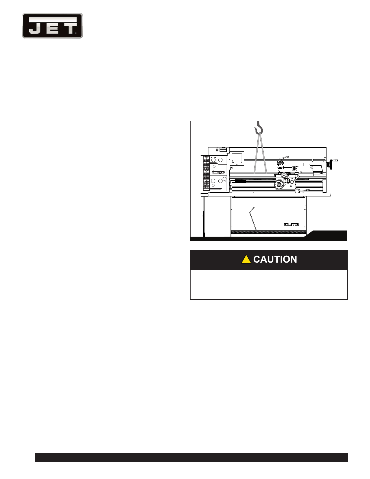
7. With properly rated lifting equipment, slowly raise lathe
off shipping pallet. (See Figure 4). Do not lift lathe by
the spindle.
H
L
RPM
TOOGLE
STOP LATHE TO
CHANGE SPEED
32 36 40 48 56
28
20 24
10 12
14
18
9
16
8
0.00280.0025 0.00230.0019 0.0016
0.00570.0051 0.00460.0038 0.0032
0.01150.0102 0.0092 0.00760.0065
0.01150.0102 0.0092 0.00760.0065
0.02300.0204 0.01840.0153 0.0131
0.04600.0409 0.03680.0307 0.0263
8
22
11
5.5
23
11.5
5.75
3 3 3
9 10 12 14
75 6
2.5 3 3.5
4.5
2.25
4
2
T.P.I
127
26
52
127
52
26
127
40
44
127
40
46
127
40
52
26
13
6.5
127
26
52
inch
127
52
26
mm
120
127
26
52
35
40
30
50
PC
MM
0.5 0.6
0.80.8 0.90.9
1.81.61.751.51.21.0
2.0 2.4 3.0 3.5 3.2 3.6
0.750.875
30
6050605030
30304040
1.8751.125 1.25
3.752.25
1.0
2.0
4.0 4.5 5.0 7.5 8.0
4.0
2.0 2.4 2.5 3.0
4.8 5.0 6.0
9.6 10 12
2.5
Leadscrew 8 TPI
B
2
3
A
C
1
4 5
Fig. 4
!
Confirm that all suspension equipment is properly
rated and in good condition for lifting lathe. Do not
allow anyone beneath or near load while lifting.
8. T he lathe can be placed upon the cast iron leveling
pads under each foot hole, and adjusted using the
adjusting bolts with hex nuts. Or, it may be secured
to the floor using bolts placed head-down in the
concrete, and using shims where needed to level
the machine. Refer to Figure 1 for mounting hole
dimensions.
6.1 LEVELING THE LATHE
It is imperative that the lathe be on a level plane; that is,
where headstock and tailstock center points remain aligned
throughout the tailstock travel, with the bed ways absent of
twist and thus parallel to the operational center line.
A lathe which is not properly leveled will be inaccurate,
producing tapered cuts. Also, the center point of the
tailstock will vary as it is positioned along the bed, thus
requiring constant readjustment of the set of the tailstock.
11
E-1236VS
Fig. 5
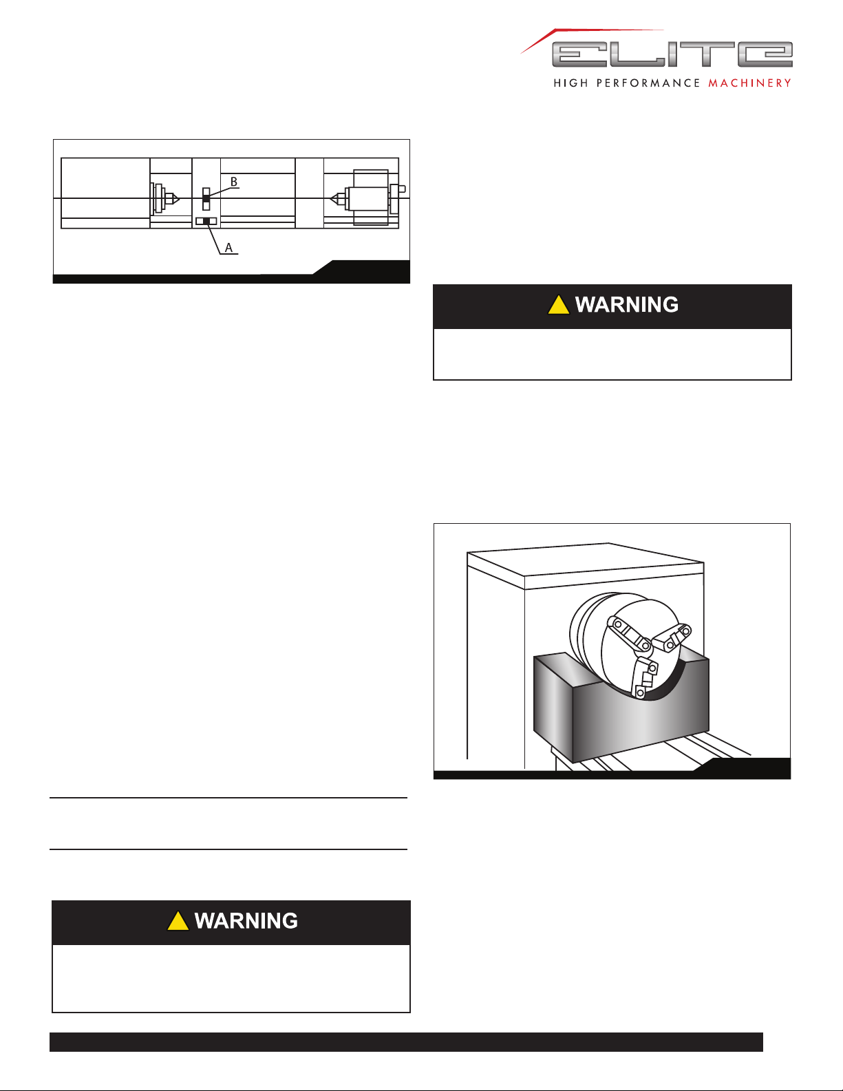
9. Use a machinist’s precision level on the bed ways both
front to back and side to side, as shown in Figure 5.
Take the reading in one direction every ten inches.
Make sure the ways are clean and free of any debris
before placing a level upon them.
10. Deviation over bed length (see Figure 5):
(a) Maximum 0.02/1000mm
(b) Maximum 0.04/1000mm
11. Tighten foot screw nuts evenly to avoid distortion.
12. Leveling should be inspected occasionally, and
especially if the accuracy of the lathe begins to
diminish.
6.2 COMPLETING INSTALLATION
13. Exposed metal surfaces have been coated with a
rust protectant. Remove this using a soft rag and mild
commercial solvent or kerosene. Do not use paint
thinner, gasoline, or lacquer thinner, as these will
damage painted surfaces. Cover all cleaned surfaces
with a light film of SAE-20W machine oil, such as Mobil
DTE Oil Heavy Medium.
14. Open the end gear cover. Clean all components of the
end gear assembly and coat all gears with a heavy,
non-slinging grease. Close the end gear cover.
Note: A limit switch prevents the lathe from
operating when the end gear cover is open.)
6.3 CHUCK PREPARATION
!
Read and understand all directions for chuck
preparation. Failure to comply may cause serious
injury and/or damage to the lathe.
The three-jaw scroll chuck is shipped pre-installed on the
lathe. It can be used for clamping cylindrical, triangular and
hexagonal stock, and has reversible jaws.
The four-jaw chuck has independently adjustable jaws, and
permits the holding of square and asymmetrical pieces.
It also enables accurate concentric set-up of cylindrical
pieces.
!
Chucks are heavy; use an assistant to help
remove.
Before removing a chuck, place a flat piece of thick
plywood across the bedways under the chuck to prevent
damage to the bedways should the chuck fall from your
hands. Alternatively, many users make a wood chuck
cradle that sits atop the ways and accepts the specific
diameter of chuck, for easier installing and removal. Figure
6 shows an example.
Fig. 6
To remove a chuck from the spindle:
1. Support the chuck while turning six camlocks 1/4-turn
counterclockwise, using the chuck wrench from the
tool box. See Figure 7.
2. Carefully remove the chuck from the spindle and place
on a firm work surface. If the spindle seems stuck, use
a mallet at various points on the back side to help free
it from the spindle.
3. Inspect the camlock studs. Make sure they have not
become cracked or broken during transit. Clean all
parts thoroughly with solvent. Also clean the spindle
and camlocks.
12
1236 Lathe
Fig. 7A
4. Cover all chuck jaws and the scroll inside the chuck
with #2 lithium tube grease. Cover the spindle,
camlocks, and chuck body with a light film of 20W oil.
Fig. 7
Cam Release
Line
B
B
A
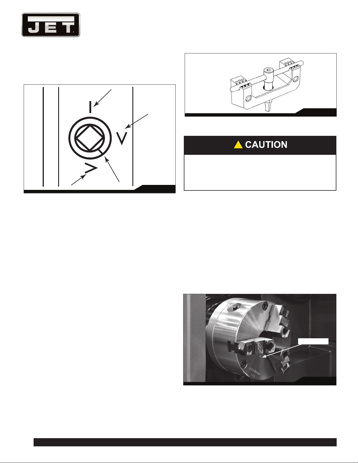
5. Lift the chuck up to the spindle nose and press onto
the spindle. Tighten in place by turning the camlocks
1/4 turn clockwise. The index mark (A, Figure 7) on the
camlock should be between the two indicator arrows
(B) when tight, as shown in Figure 7.
• If the index mark (A) is not between the two
arrows, i.e. the cam turns beyond the indicator
arrows, then remove the chuck and turn the
camlock stud IN one full turn.
• If a camlock will not engage, remove the chuck
and turn the camlock stud OUT one full turn.
6. Make sure chuck is secure on the spindle with the
camlocks correctly engaged.
6.4 BREAK-IN PERIOD
Do not run the lathe above 560 RPM for the first six hours
of operation, to allow gears and bearings to adapt and run
smoothly.
6.5 CHUCK KEY BRACKET
The chuck key bracket (Figure 7A) is located on the cabinet
below the headstock. The chuck key must be placed within
the bracket for lathe to operate. A sensor in the bracket
will deactivate spindle if key is not present - this ensures
key has been safely removed from chuck and spindle area
before starting the lathe.
7.0 MAINTENANCE/LUBRICATION
!
Lathe must be serviced at all lubrication points
and all reservoirs filled to operating level before
the lathe is put into service. Failure to comply may
cause serious damage to the lathe.
The lathe is shipped with oil in the reservoirs. Coolant is
not included.
Use clean lubricants and check levels often, including
before each working shift. To ensure proper lubrication,
oil levels should not be less than the center of the oil sight
glass. Try not to overfill, as this may cause leakage.
Unless specified otherwise, the lubrication points require a
non-detergent, ISO 68, SAE 20W oil. The recommended
brand for this lathe is Mobil DTE® Oil Heavy Medium.
1. Chuck – Lubricate the chuck daily with SAE 20W oil
through the ball oiler, shown in Figure 8.
Fig. 8
Ball oiler
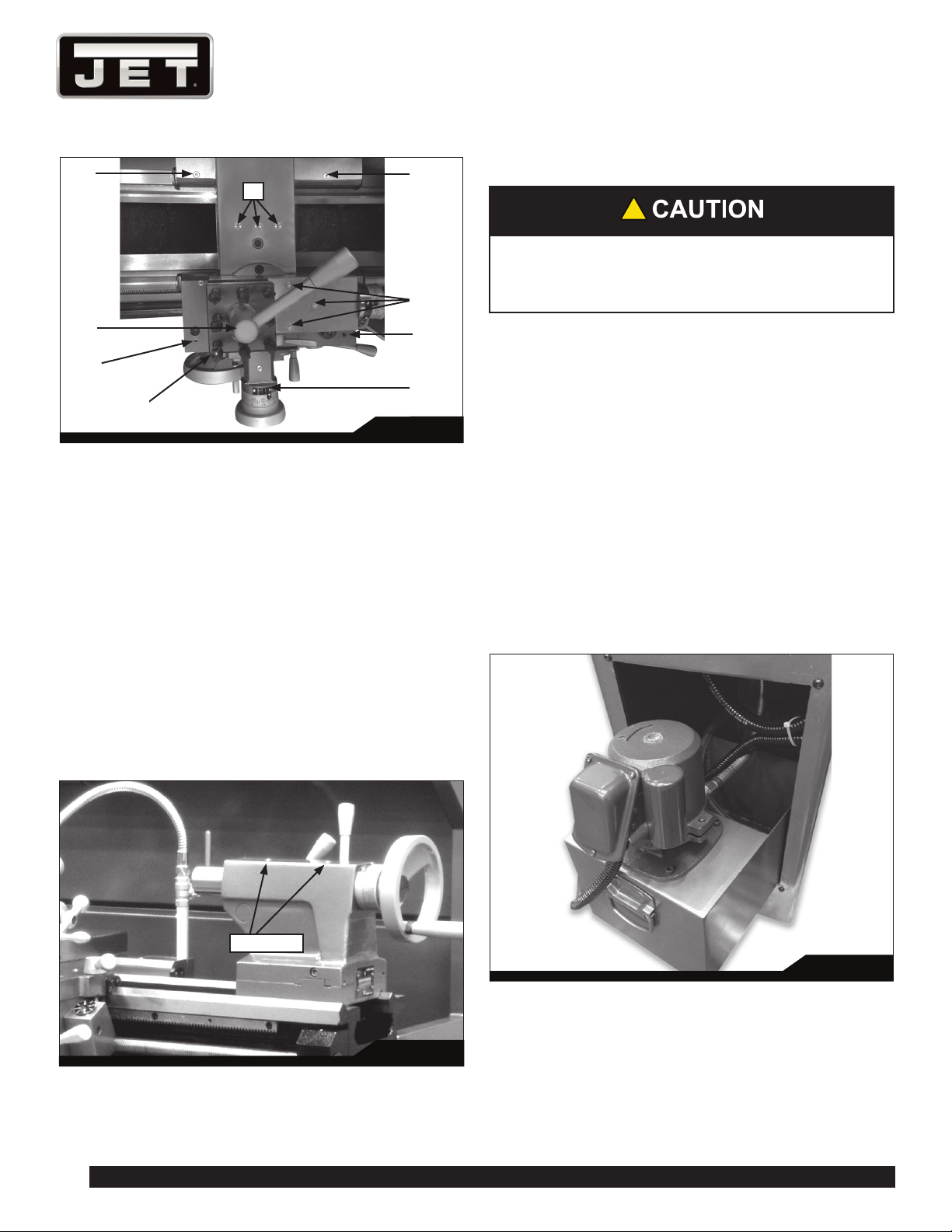
2. Headstock – Oil must be up to indicator mark in oil
sight glass on right side of headstock (A, Figure 9).
Top off with SAE 20W oil. Fill by removing the rubber
mat and unscrewing the plug (B) on top of headstock.
To drain headstock, remove drain plug (C, Figure 10).
13
E-1236VS
Drain oil completely and clean out all metal shavings,
then rinse the casting case with kerosene. Refill after
the first month of operation, then change the oil in the
headstock every two months.
Fig. 9
B
D
A
E
Fig. 10
C
F
3. Gearbox – Oil must be up to indicator mark in oil sight
glass (D, Figure 9). Top off with SAE 20W oil. To add
oil to the gearbox, remove rubber mat and unscrew oil
plug (E, Figure 9). To drain, remove drain plug from the
pipe (F, Figure 10). Drain oil completely and refill after
the first three months of operation. Then change oil in
the gearbox every six months.
4. Apron – Oil must be between indicator marks in the
oil sight glass (G, Figure 11). Top off with SAE 20W
oil. Unscrew oil plug (H, Figure 11) to fill. To drain,
remove drain plug on the underside of apron. Drain
oil completely and refill after the first three months of
operation. Then, change oil in the apron annually.
Fig. 11
H
G
5. Saddle – The anti-dust felt on both ends of the saddle
(Figure 12) should be cleaned weekly with kerosene. If
the felt becomes damaged, replace it.
Fig. 12
Felt
6. V-Belts – Regularly check and adjust the tightness of
the v-belts to prolong their service life.
7.1 BALL OILER LOCATIONS
All ball oilers must be lubricated with SAE-20W oil (Mobil
DTE® Oil Heavy Medium), as follows. Refer to Figures 13
and 14.
7. Cross Slide – Daily lubricate one ball oiler on the
handwheel housing (K, Figure 14) and three ball oilers
on the platform (L, Figure 14).
14
1236 Lathe
Fig. 14
K
O
OO
O
N
P
L
M
8. Compound Rest – Daily lubricate two ball oilers (M,
Figure 14) on top of compound rest.
9. Tool Post – Regularly clean dirt and coolant around the
tool post to maintain its re-positioning accuracy. Daily
lubricate one ball oiler on top the clamping hub (N,
Figure 14).
10. Saddle – Daily lubricate four ball oilers (O, Figure 14)
and one ball oiler on the handwheel shaft (P, Figure
14).
13. Tailstock – Daily lubricate two ball oilers (Figure 15) on
top of tailstock.
The anti-dust felt beneath the tailstock that runs along
the ways should be cleaned weekly with kerosene. If
the felts become damaged, replace them.
Fig. 16
Ball oilers
7.2 COOLANT PREPARATION
!
Follow local regulations and/or coolant
manufacturer’s recommend-dations for use, care
and disposal.
1. Remove access cover on the tailstock end of the
lathe stand (Figure 17). Make sure coolant pump
has not shifted during transport. Pour four gallons
(approximate) of coolant mix into the reservoir. Use the
gauge to determine when full.
2. After machine has been connected to power, turn on
coolant pump and check to see that coolant is cycling
properly. Flow is controlled by the tap at the base of
the nozzle.
3. Reinstall access cover.
To change coolant, remove access panel from rear of
lathe. Pull the coolant tray and dump dirty coolant. Clean
the tray of any chips or residue. Refill with proper amount
of new water soluble coolant.
Fig. 17
15
E-1236VS
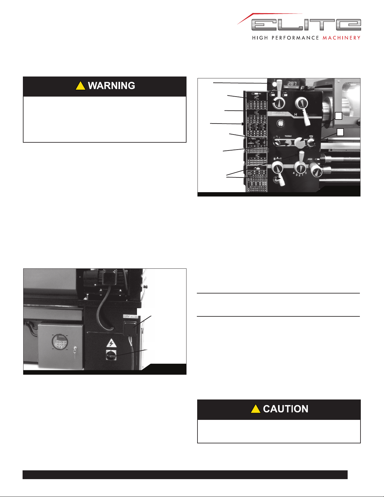
8.0 ELECTRICAL CONNECTIONS
!
Electrical connections must be made by a
qualified electrician in compliance with all relevant
codes. This machine must be properly grounded
while in use to help protect the operator from
electrical shock and possible fatal injury.
The main motor is rated for 230 volt only. Confirm that
power available at the lathe’s location is the same rating as
the lathe.
IMPORTANT: The lathe must be wired properly
and phased correctly. The spindle should rotate
counterclockwise (as viewed from the tailstock end) while
the feed rod rotates clockwise (as viewed from the tailstock
end). If the phasing needs correction, disconnect lathe
from power source and switch any two of the three power
leads (not the green ground wire).
If wiring for single phase input, connect at R and T, as
shown in the wiring diagram in section 14.0.
Make sure the lathe is properly grounded.
Fig. 18
Cable receiver
Main switch
9.0 BASIC CONTROLS
Fig. 19
B
C
D
F
I
G
E
H
A
1. Control Panel: Located on front of headstock.
• Power Indicator Light (A, Figure 19).
Illuminates whenever lathe is receiving power.
• Coolant On-Off Switch (B, Figure 19).
Activates coolant pump.
• Jog Button (C, Figure 19).
Quickly press and release to rotate spindle.
• Emergency Stop Button (D, Figure 19).
Shuts down all machine functions.
Note: Lathe will still have power. Twist button
clockwise to reset.
• Motor Speed Switch (E, Figure 19).
Turn to select high or low speed.
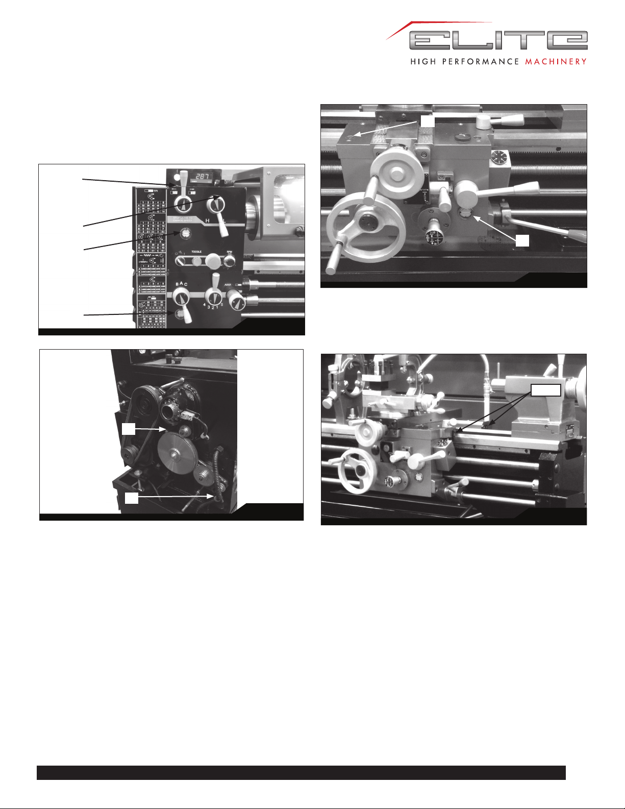
2. Speed Selection Levers (F, Figure 19): Move levers
left or right to desired spindle speed, according to
accompanying chart.
3. Feed Direction Knob (G, Figure 19): Rotating the
knob changes direction of feed. Center position is
neutral.
!
Do not move feed direction knob (G) while
machine is running.
16
1236 Lathe
4. Lead and Feed Selector Levers (I, Figure 19):
Used conjunctively to set up for threading or feeding,
according to the accompanying chart (H, Figure 19).
Fig. 20
K
R
Q
L
M
U
O
J
N
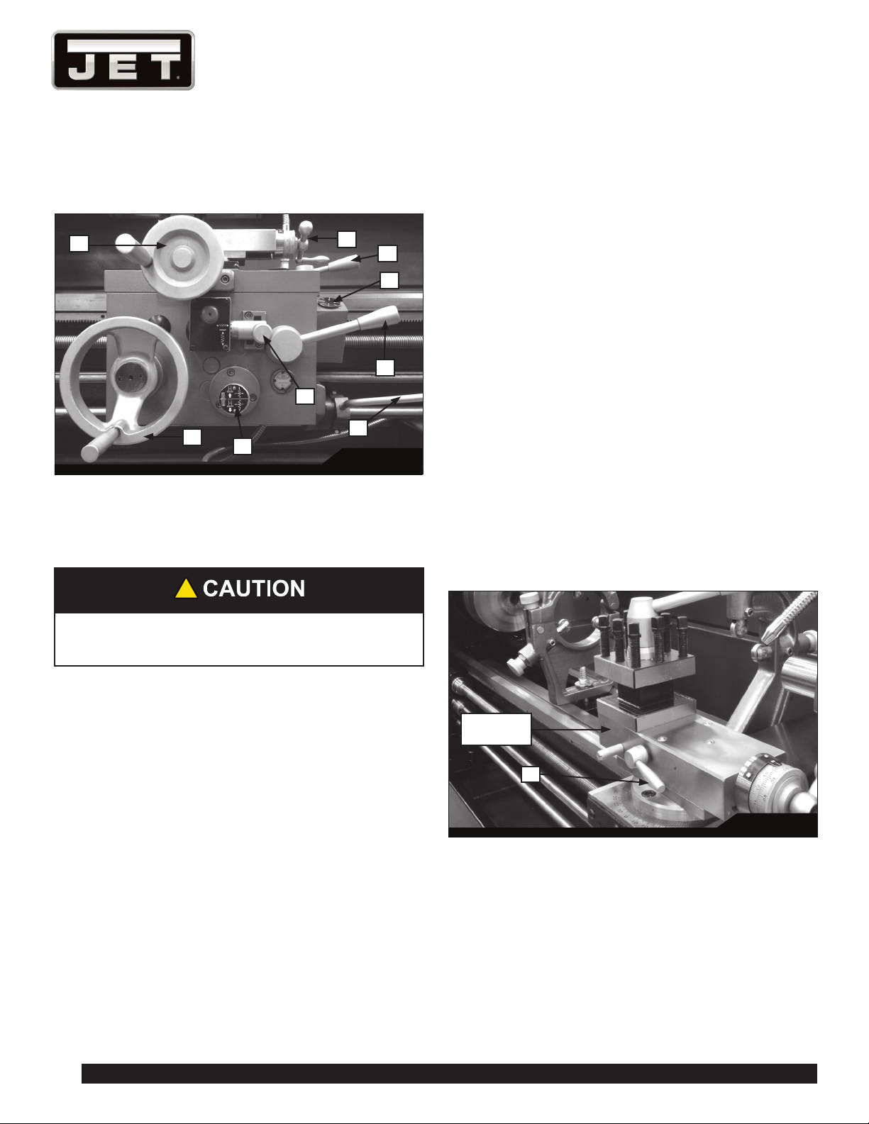
5. Carriage Lock (J, Figure 20): Located on top right of
carriage. Turn clockwise to lock, counterclockwise to
unlock.
!
Carriage lock must be loose before moving
carriage or damage to lathe may occur.
6. Carriage Handwheel (K, Figure 20): Located on
the apron. Rotate handwheel clockwise to move the
carriage assembly toward the tailstock (right). Rotate
the wheel counterclockwise to move the carriage
assembly toward headstock (left). A scale is mounted
to the ring, graduated in 0.005 inch increments, and
can be calibrated by loosening the thumb screw lock
and rotating the ring as needed. Always retighten ring
before using the feed.
7. Feed Direction Lever (O, Figure 20): Push in to move
from left to right and pull out to move from right to left.
8. Half Nut Lever (M, Figure 20): Located on the front
of the apron assembly. Engages the leadscrew for
threading operations.
9. Spindle Direction Control Lever (N, Figure 20). Move
the lever to the right so that its tab clears the notch,
then down for forward spindle rotation, or up for reverse
spindle rotation. Allow the spindle to come to a stop
before changing directions. Position lever in neutral
position (tab in notch) before shutting off the lathe.
10. Feed Engagement Lever (L, Figure 20): Push to
one of three positions; Up for crossfeed; Down for
longitudinal; the middle position allows screws to be
cut by engaging the half nut.
11. Threading Dial (Q, Figure 20): Indicates the point on
the leadscrew where the half nut can be re-engaged
to continue inch threading.
12. Cross Slide Handwheel (R, Figure 20): Located
above the apron assembly. Clockwise rotation
moves the cross slide toward the rear of machine.
The accompanying scale is graduated in 0.002 inch
increments, and can be calibrated by loosening the
thumb screw lock and rotating the ring as needed.
Always re-tighten ring before using the feed.
The cross slide lock is located at the right of the cross
slide (S, Figure 21).
13. Compound Rest: Located on top of the cross slide
and can be rotated 360° after loosening the lock.
There are calibrations in degrees at the base of the
rest to assist in placement to the desired angle.
Fig. 21
Compound
rest
S
14. Compound Rest Handle (U, Figure 20): Rotate
clockwise or counterclockwise to position. The
accompanying scale on the collar is graduated in
0.001 inch increments.
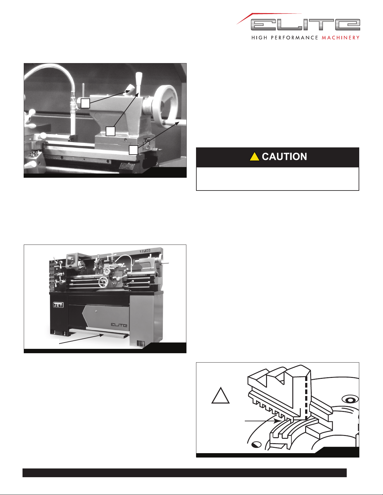
15. Tailstock Quill Clamping Lever (W, Figure
22): Rotate clockwise to lock the sleeve. Rotate
counterclockwise to unlock.
17
E-1236VS
Fig. 22
W
Y
X
17. Tailstock Quill Traverse Handwheel (X, Figure
22): Rotate clockwise to advance the quill and
counterclockwise to retract it. Fully retract it to eject a
center or drill chuck.
16. Tailstock Clamping Lever (Y, Figure 22): Lift up to
lock. Push down to unlock.
Fig. 23
Foot break
18. Foot Brake (Figure 23): For emergency shutdown of
all lathe functions. The connecting rod mechanism is
in the bed stand, and activates a brake strap at the
main motor. (Caution: Lathe still has power.) The foot
brake is not intended for normal stopping of the lathe.
Overuse can result in hastened wear of brake parts.
10.0 OPERATION
The operator should consult shop manuals such as
“Machinery’s Handbook” for cutting speeds and feeds
appropriate to specific workpieces. Correct feed depends
upon material to be cut, cutting operation, tool type,
chucking rigidity, depth of cut, and desired surface quality.
IMPORTANT: Allow a break-in period for the new lathe so
that gears and bearings can adapt; do not run the lathe
above 560 RPM for the first six hours of operation.
!
The following points must be observed when
operating the lathe:
• Never turn any handles or levers when spindle is
at high speed.
• Change spindle speed only after spindle stops.
• Change feed rate only when spindle is at low
speed or is stopped.
• Never exceed maximum speed limitation of the
work holding device.
• Before starting spindle, check that each handle
or lever is at correct position to ensure normal
engagement of gears. The spindle direction control
lever should be at neutral position.
• If the brake becomes ineffective, turn off machine
and adjust brake immediately.
• When operating spindle direction control lever,
always turn it to correct position; never use “pre-
position” for cutting at a reduced speed.
• Jaw teeth and scroll must be fully engaged, to
prevent the jaws from breaking and being thrown
from chuck (see Figure 24).
Improper
engagement
!
Fig. 24
18
1236 Lathe
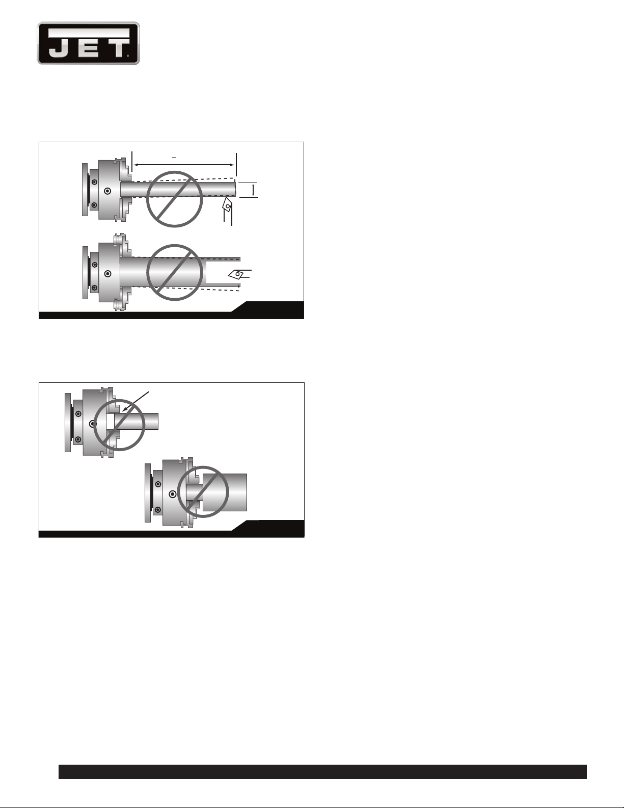
• Avoid long workpiece extensions, as parts may
bend or fly off (see Figure 25). Use rests or the
tailstock for support.
L
L
>
3xD
D
Fig. 25
• Avoid short clamping contact (Figure 26, A) or
clamping on a minor part diameter (Figure 26, B).
Face-locate the workpiece for added support.
A
B
Insufficient contact
Small diameter clamping
Fig. 26
10.1 TOOL SETUP
The cutting angle is correct when the cutting edge is in
line with the center axis of workpiece. Use the point of the
tailstock center as a gauge and shims under the tool to
obtain correct center height.
Use a minimum of two clamping screws to secure each
tool.
10.2 SPINDLE SPEED
The spindle speed is variable between 40 and 2000 RPM.
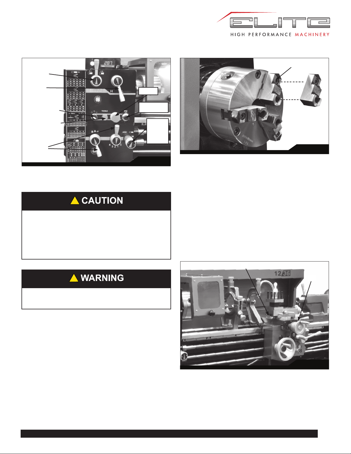
10.3 FEED AND THREAD SELECTION
To obtain various feed settings and thread pitches, the two
levers (I, Figure 27) are used conjunctively. Position the
two levers according to the Feed and Thread Chart on the
front of the headstock.
TIP: When selecting feed/speed correlations, remember
the general principal that high speeds complement fine
feeding, and low speeds are better for coarse feeding.
10.4 THREAD CUTTING
Threading is performed in multiple passes, with increasing
depths in succeeding cuts. It is recommended that test cuts
be made on scrap material and the results checked before
proceeding with regular material.
1. Move feed direction knob (G, Figure 27) to desired
direction, for right-hand or left-hand threads.
2. Set spindle (F, Figure 27) to desired speed. Use lowest
speed possible when threading.
3. Select desired thread using thread pitch levers (I,
Figure 27) in conjunction with the charts on the
headstock.
4. Set feed direction lever (see L, Figure 20) to correct
position (neutral).
5. Engage the half nut (M, Figure 20). The half nut must
be engaged during the entire threading process when
doing metric, diametral, and modular threading.
6. When tool reaches end of cut, disengage and back out
the tool to clear the workpiece.
7. Reverse direction to allow cutting tool to return to its
starting point.
8. Repeat process until desired result is obtained.
19
E-1236VS
Fig. 27
Threading/
Carriage
traverse
selector
knob
Coolant on/off
Jog button
E-Stop
Spindle Speed
adjustment
I
G
F
11.0 ADJUSTMENTS
!
Adjustments to the lathe, especially those
involving alignments of bearings, spindle,
leadscrew, clutch, etc., should only be performed
by qualified personnel, as improper alignments
can damage the machine and/or create a safety
hazard.
!
Turn off main switch and press emergency stop
button before making adjustments to lathe.
11.1 CHUCK JAW REVERSAL
The three jaws on the scroll chuck are reversible, to hold
stock with larger diameters. See Figure 29. Loosen two
screws with the provided hex key, remove jaw, and rotate
it 180-degrees. Re-install jaw, and tighten each screw in
increments until fully tightened.
Fig. 29
Loosen screws
Reversed jaw
11.2 GIB ADJUSTMENTS
After a period of time, some moving components may
need adjustment for play (or “backlash”) due to wear. Do
not overtighten gib screws as this can hasten wear to
components.
Saddle – Turn screws on either side of saddle at the rear to
adjust drag on saddle.
Cross Slide – Gib screws are located at front and rear of
slide opposite to one another (A, Figure 30). To adjust drag,
loosen rear gib screw one turn, and tighten front gib screw
a quarter turn. Rotate handwheel to check play. Repeat as
needed until slide moves freely without play. Gently tighten
rear gib screw.
Fig. 30
A
B
Compound Rest – Gib screws are located at front and
rear of compound rest (B, Figure 30). To adjust, use same
method as for Cross Slide.
20
1236 Lathe
11.3 TAILSTOCK ADJUSTMENTS
The tailstock can be offset to cut shallow tapers up to 5°
angle. See Figure 32.
1. Loosen tailstock in position by lowering locking handle
(D).
2. Alternately loosen and tighten front and rear screws
(E). [Only front screw shown.]
The scale (F) on the end of the tailstock indicates amount
of offset, and helps when re-centering.
If the clamping force needs to be adjusted, use the hex nut
beneath the tailstock body.
Fig. 32
F
E
D
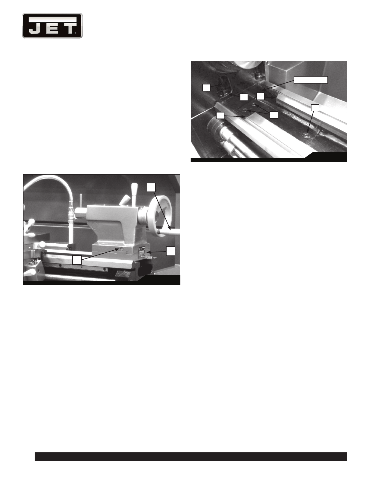
11.4 GAP SECTION
1. To remove the gap section (Figure 33), remove four
socket head cap bolts (A) and two socket bolts at the
ends of the rails (B).
2. Remove two tapered alignment pins (C) by placing
the provided gap bridge pin driver (D) over them and
threading its screw down into them, until the pins are
loosened enough to be pulled out.
3. Remove gap section.
Fig. 33
C
Gap Section
D
C
B
B
A
To reinstall gap section:
1. Thoroughly clean bottom and ends of gap section.
2. Set gap section in place and align the ends.
3. Insert the tapered pins into their holes through gap
and into lathe bed.
4. Re-insert the six bolts (A,B) and tighten alternately
until all are snug. Make sure gap remains aligned with
ways while tightening screws.
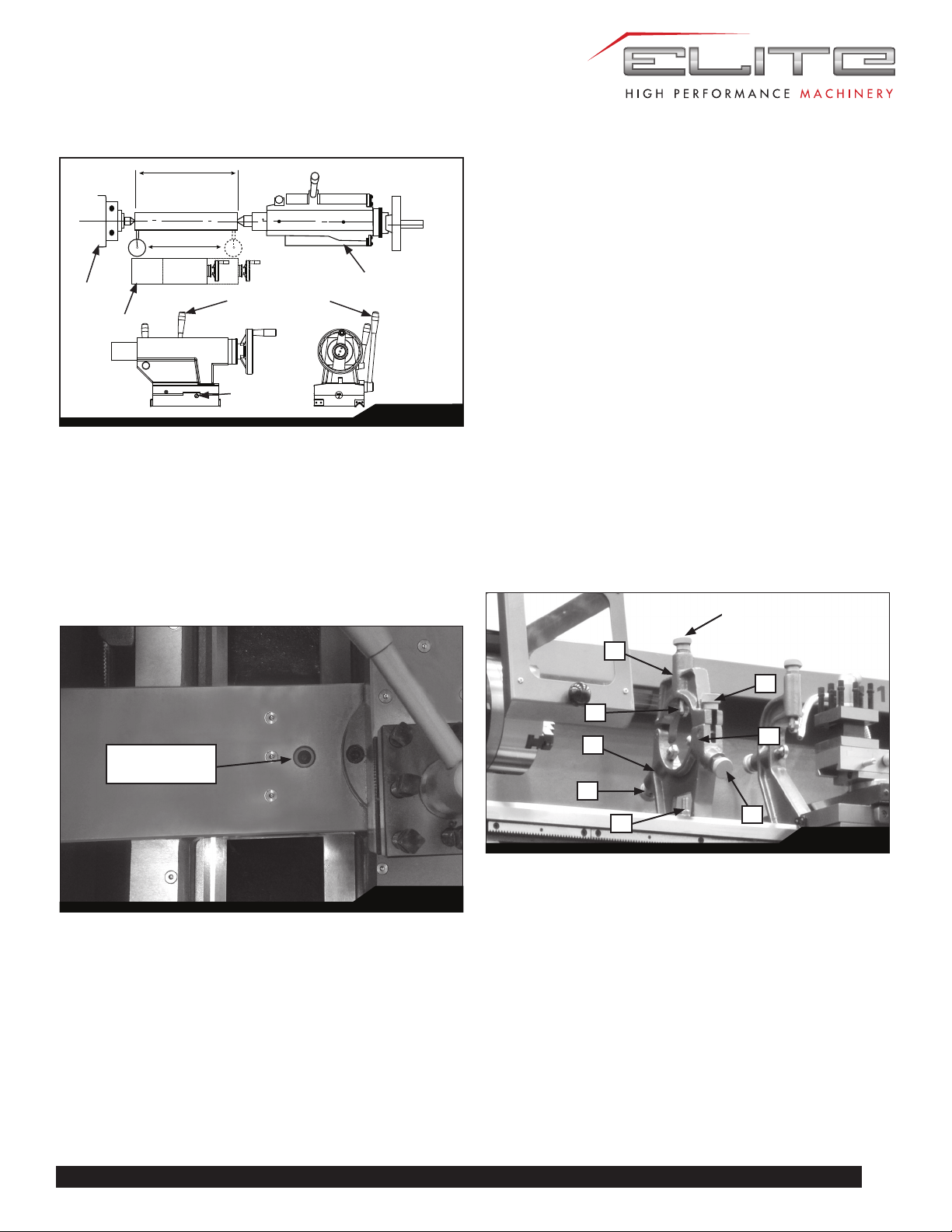
11.5 ALIGNING TAILSTOCK TO HEADSTOCK
Headstock and Tailstock have been aligned at the factory
and should not require attention. If future adjustment
should ever be needed, proceed as follows. (Make
sure that twist in the lathe bed is not contributing to the
problem; refer to sect. 8.1.)
1. Fit a 12” ground, center-drilled, steel bar between
centers of headstock and tailstock (Figure 34).
2. Fit a dial indicator to the top slide and traverse the
center line of the bar. If it indicates a taper, adjustment
is needed.
3. Align tailstock using the off-set screws at front and
back (see E, Figure 32) until tailstock is aligned.
21
E-1236VS
12”
Fig. 34
Tailstock clamp lever
Set-over screws
Headstock
Topslide
Tailstock
11.6 CROSS SLIDE NUT ADJUSTMENT
The cross slide moves via a lead screw which drives a nut.
This can be adjusted if backlash develops. Backlash is
identified by turning the cross slide handwheel left and right
– if there is a delay before any cross slide movement, the
nut needs adjusting.
Tighten or loosen the screw shown in Figure 35 until
backlash is adjusted out.
Fig. 35
Screw for
backlash adjust
11.7 SHEAR PIN REPLACEMENT
The lead screw and feed shaft are equipped with shear
pins, which are designed to break in order to protect the
drive system against overload. A broken shear pin must be
replaced.
Knock out the broken pin; line up the holes and insert
new pin.
11.8 STEADY REST ADJUSTMENT
Always lubricate the fingers with grease before using
the steady rest. The point at which the fingers contact
the workpiece require continuous lubrication to prevent
premature wear.
To set the steady rest (see Figure 36):
1. Loosen hex nut (A) to slide steady rest along the ways.
2. Loosen knurled handle (B) until it can be pivoted out of
the slot.
3. Loosen three lock knobs (C), and back off the fingers
(D) using knurled handles (E).
4. Pivot the collar on its hinge and position steady rest
around workpiece.
5. Firmly tighten hex nut (A).
6. Set the fingers snugly to work piece and secure by
tightening locking knobs. Fingers should be snug but
not overly tight.
Fig. 36
E
C
D
C
E
A
E
C
B
11.9 FOLLOW REST ADJUSTMENT
The follow rest mounts to the saddle with two socket
head cap bolts. The follow rest should be mounted so that
locking knobs point away from chuck.
The sliding fingers are set similar to those on the steady
rest – free of play, but not binding.
Always lubricate the fingers sufficiently with grease before
operating.

22
1236 Lathe
Workpiece material Speed (sfm) Feed (lpr)
Aluminum 2021 to 6061 500 0.002
Brass 75 0.001
Bronze 70 0.001
Cast Iron Gray 35 to 125 0.0015 to 0.004
Ductile 15 to 125 0.001 to 0.004
Malleable 35 to 170 0.0015 to 0.003
Copper 101 to 757 85 to 90 0.002
834 to 978 340 0.003
Magnesium AZ, AM, EZ, ZE, HK
types
500 0.002
Nickel Nickel 200 to 230 85 0.002
Monel 15 to 60 0.001 to 0.0015
Inconel, Waspaloy 15 0.002
Hastelloy 10 to 15 0.002
Plastic TFE, CTFE 250 0.002
Nylon 350 0.002 to 0.003
Phenolic 350 0.003
Stainless Steel 201 to 385 65 to 85 0.001 to 0.0015
405 to 446 90 0.0011
15-5 PH, 16-6 PH,
14-4 PH
30 to 60 0.0006 to 0.0012
Steel 1005 to 1029 80 to 140 0.001 to 0.002
1030 to 1055 35 to 115 0.0009 to 0.0015
1060 to 1095 30 to 80 0.0007 to 0.001
10L45 to 10L50 40 to 140 0.0009 to 0.0015
12L13 to 12L15 225 to 280 0.003 to 0.0035
41L30 to 41L50 20 to 110 0.0007 to 0.0015
4140 to 4150 20 to 115 0.0007 to 0.0015
4140 (35 HRC) 70 0.001
8617 to 8622 40 to 120 0.001 to 0.0016
M-1 to M-6 60 0.0013
H-10 to H-19 20 to 80 0.007 to 0.0011
D-2 to D-7 45 to 60 0.001
A-2 to A-9, 01 to 07 45 to 60 0.001
W-1, W-2 110 0.0015
M-50, 52100 20 to 85 0.0007 to 0.0015
Titanium TI-6AI-6V 45 0.001
12.0 RECOMMENDED CUTTING SPEED
OF LATHE
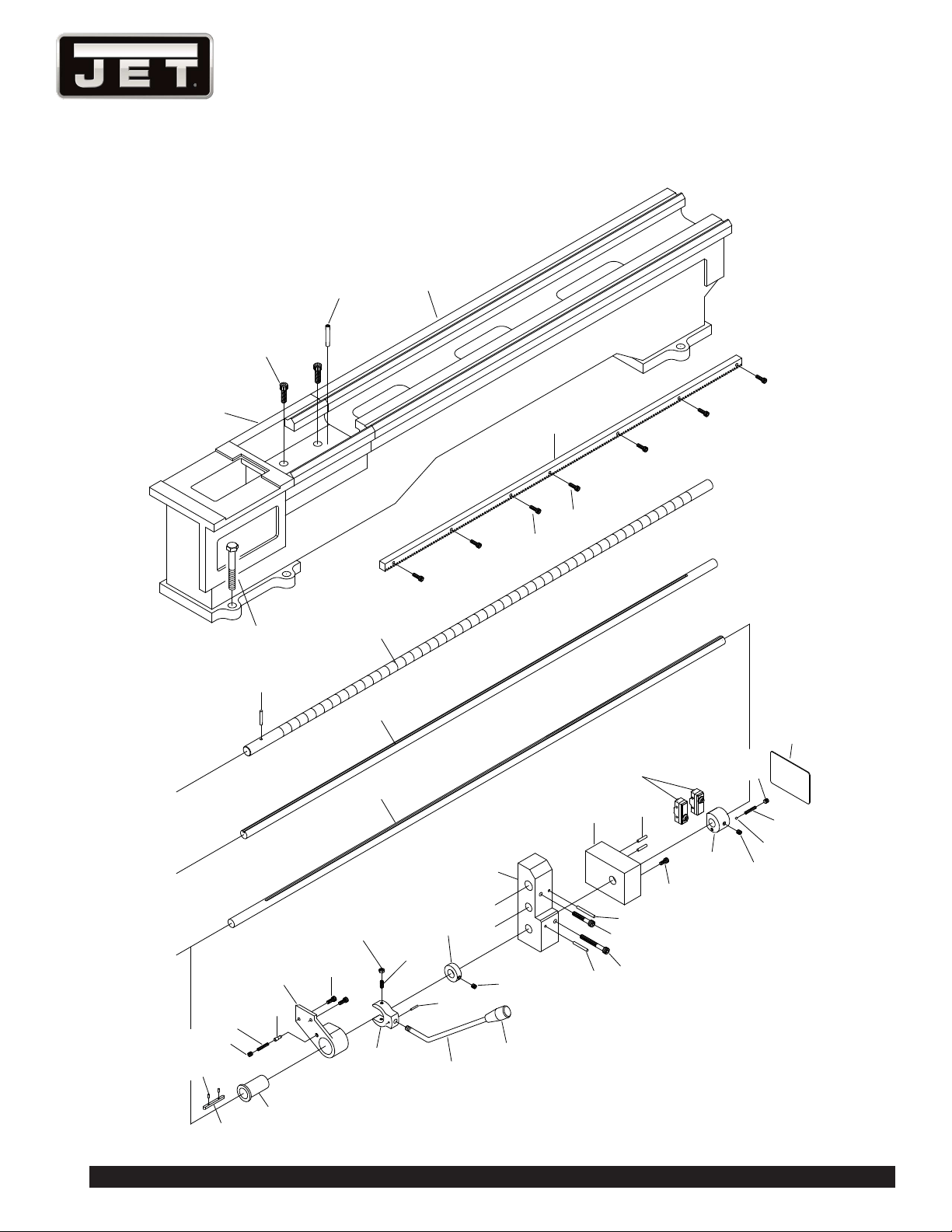
13.0 REPLACEMENT PARTS —
E-1236VS
Replacement parts are listed on the following pages.
To order parts or reach our service department, call
1-855-336-4032, Monday through Friday, 8:00 a.m. to 5:00
p.m. CST. Having the Model Number and Serial Number
of your machine available when you call will allow us to
serve you quickly and accurately.
JET
®
427 New Sanford Road
LaVergne, Tennessee 37086
www.jettools.com
Phone: 855-336-4032
23
E-1236VS
OIL
L
K
218
1800
40
330
L
K
L
H
1
2
4
3
5
6
7
8
10
13
11
12
13
9
14
15
16
17
18
19
20
21
22
14
23
24
25
20
8
9
10
7
14
26
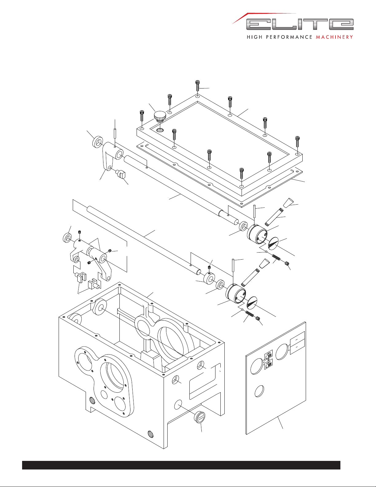
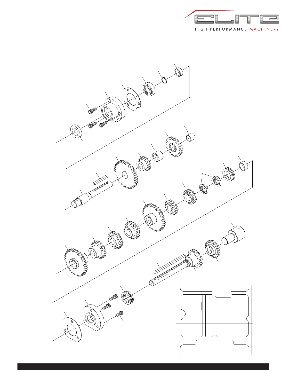
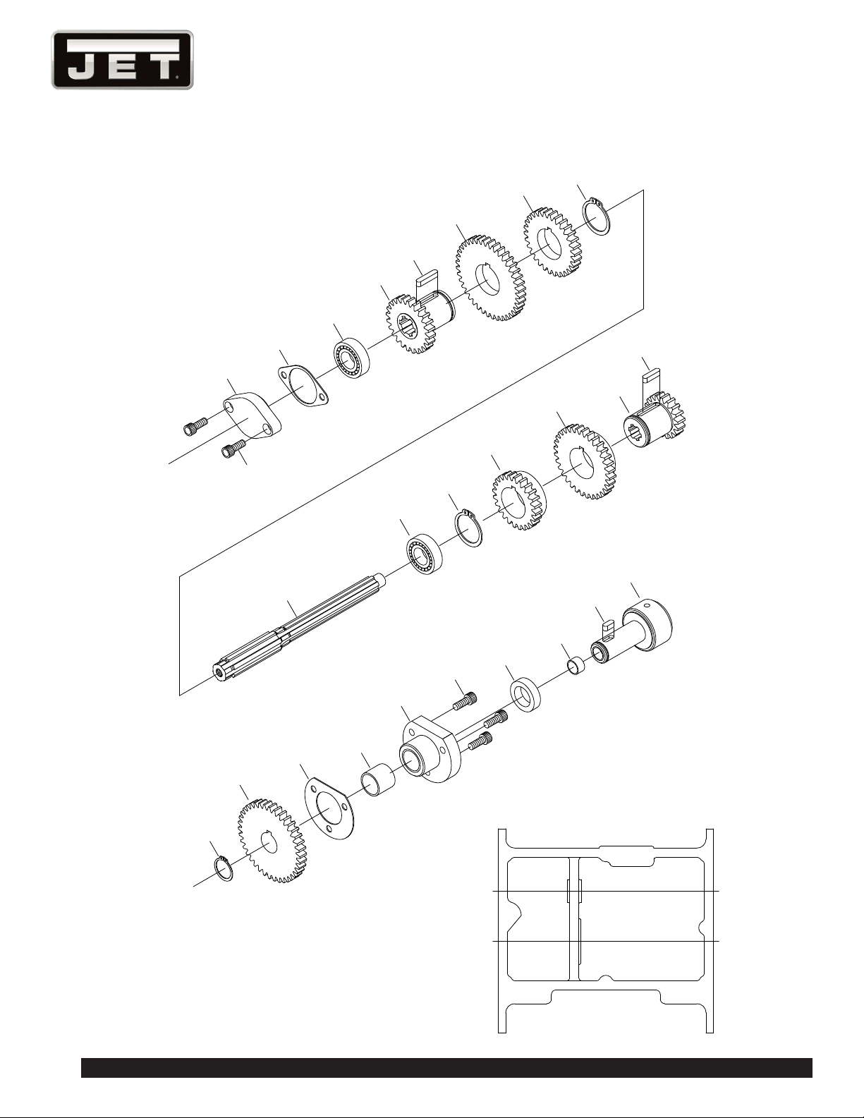
HEADSTOCK ASSEMBLY
24
1236 Lathe
S
A
B
C
S
29
30
31
32
33
34
3
35
36
37
38
39
40
20
41
42
43
44
45
46
47
48
49
50
52
51
53
54
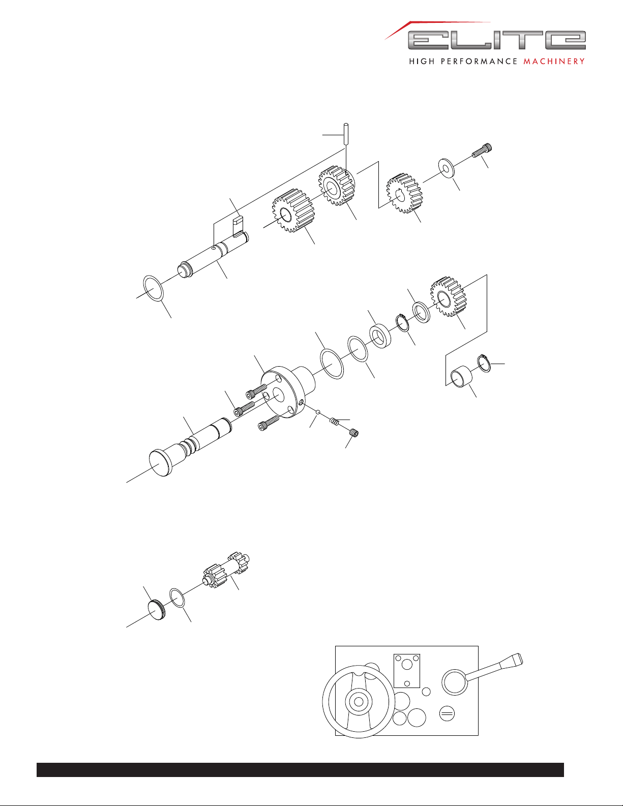
HEADSTOCK ASSEMBLY
25
E-1236VS
S
A
B
C
A
B
C
55
56
57
58
59
60
61
62
63
64
65
66
67
68
69
70
70
62
62
59
71
72
73
74
75
76
77
78
79
80
81
82
83
84
70
75
HEADSTOCK ASSEMBLY

26
1236 Lathe
HEADSTOCK ASSEMBLY PARTS LIST
Index No. Parts No. Description Size Qty.
1 EBL1236VS-A01 Headstock Casting 405*235*238 1
2 EBL1236VS-A02 Headstock Cover 405L*235W*23H 1
3 TS-1503061 Socket Head Cap Screw M6×25mm 13
4 EBL1236VS-A04 Plug 3/4 in.(P.V.C) 1
5 EBL1236VS-A05 Gasket For Headstock
Cover 4163
1
6 EBL1236VS-A06 Index Plate 2
7 EBL1236VS-A07 Handle Ø45*35L 2
8 TS-1524011 Set Screw M8x8L 2
9 EBL1236VS-A09 Spring 1/4 in × 27mm 2
10 SB-1/4 Ball Steel 1/4 in. dia 2
11 EBL1236VS-A11 Lever 2
12 EBL1236VS-A12 Handle 2
13 EBL1236VS-A13 Pin 5×40mm 2
14 EBL1236VS-A14 Oil Seal TC 16×26×7mm 2
15 EBL1236VS-A15 Shaft Ø19.5*425L (Ø16) 1
16 EBL1236VS-A16 Pin Ø5×30mm 1
17 EBL1236VS-A17 Oil Seal TC 19×32×8mm 1
18 EBL1236VS-A18 Shaft Fork PCD 62*50L 1
19 EBL1236VS-A19 Shift Fork Ø19*26.5 2
20 TS-1523011 Set Screw M6x6L 4
21 EBL1236VS-A21 Collar 1
22 EBL1236VS-A22 Shaft Ø19.5*425L (Ø16) 1
23 EBL1236VS-A23 Shift Fork 122L 55h 2
24 EBL1236VS-A24 Shift Fork 2
25 EBL1236VS-A25 Headstock Plate 1
26 EBL1236VS-A26 Oil Sight 1-1/8 in.(28mm.) 1
29 EBL1236VS-A29 Main Spindle Ø117.5*408.1L 1
30 EBL1236VS-A30 Key 8×70mm 1
31 EBL1236VS-A31 Key 7×40mm 1
32 EBL1236VS-A32 Cover Ø145*Ø80.5*25W 1
33 EBL1236VS-A33 Gasket For 4162 1
34 EBL1236VS-A34 Oil Seal TC Ø80×Ø105×Ø10mm 1
35 BB-32212 Bearing No.32212 1
36 EBL1236VS-A36 Gear 2M 82T 1
37 EBL1236VS-A37 Collar Ø75*Ø55*26 key 8*4.5 1
38 EBL1236VS-A38 Gear 2M 43T 1
39 EBL1236VS-A39 Collar Ø52.25*Ø52*20W key 7*3.5 1
40 EBL1236VS-A40 Gear 1.75M 45T 1
41 EBL1236VS-A41 Circlip S-50mm 1
42 BB-30210 Bearing No.30210 1
43 EBL1236VS-A43 Oil Seal TC 65×85×12mm 1

27
E-1236VS
Index No. Parts No. Description Size Qty.
44 EBL1236VS-A44 Gasket For 4110 1
45 EBL1236VS-A45 Cover Ø123*21W 1
46 TS-1503051 Socket Head Cap Screw M6×20mm 3
47 EBL1236VS-A47 Collar Ø64.5*Ø50*20W 1
48 EBL1236VS-A48 Nut Ø75*19W 1
49 TS-1503031 Socket Head Cap Screw M6×12mm 2
50 EBL1236VS-A50 Index Ring Ø72*Ø45*12 1
51 EBL1236VS-A51 Cam Lock 3
52 EBL1236VS-A52 Pin 3
53 EBL1236VS-A53 Spring 3
54 EBL1236VS-A54 Screw 3
55 TS-1504051 Socket Head Cap Screw M8x25L 1
56 EBL1236VS-A56 Washer Ø44*Ø7.9*17 1
57 EBL1236VS-A57 Pulley Ø114.3*Ø21.35*50W 1
58 EBL1236VS-A58 Oil Seal TC 25×40×8mm 1
59 TS-1503041 Socket Head Cap Screw M6×16mm 6
60 EBL1236VS-A60 Cover Ø80*21L (Ø35) 1
61 EBL1236VS-A61 Gasket For 4164 1
62 EBL1236VS-A62 Circlip S-25mm 3
63 BB-6205 Bearing No.6205 1
64 EBL1236VS-A64 Shaft Ø30*302L 21*25*5 1
65 EBL1236VS-A65 Circlip S-38mm 1
66 EBL1236VS-A66 Gear 2M 60T 1
67 EBL1236VS-A67 Key 8×30mm 1
68 EBL1236VS-A68 Gear 2M 21T 1
69 BB-6204 Bearing No.6204 1
70 EBL1236VS-A70 Circlip S-20mm 3
71 EBL1236VS-A71 O-Ring 42×48×3.0mm 1
72 EBL1236VS-A72 Plug Ø47*12W 1
73 EBL1236VS-A73 Shaft Ø25*109L key 5*2.5 1
74 EBL1236VS-A74 Key 5×20mm 1
75 BB-6004 Bearing No.6004 2
76 EBL1236VS-A76 Cover P.C.D. Ø42*Ø32*32L 1
77 EBL1236VS-A77 O-Ring 34×40×3.0mm 1
78 EBL1236VS-A78 Oil Seal TC 20×32×2.5mm 1
79 EBL1236VS-A79 Collar Ø30*Ø20*16W key 7*3.5 1
80 EBL1236VS-A80 Gear 1.75M 35/45T 1
81 EBL1236VS-A81 O-Ring 20×25×2.5mm 1
82 EBL1236VS-A82 Shaft Ø25*85L 1
83 EBL1236VS-A83 Gear 1.75M 35/45T 1
84 EBL1236VS-A84 Collar Ø28*Ø20*3W 1
28
1236 Lathe
F
E
F
E
L
H
1
2
4
5
5
6
6
7
7
8
8
9
10
11
12
13
14
15
16
17
18
19
20
21
10
11
12
13
14
9
15
5
6
7
8
52
3
4
3
2
1
5
A
C
B
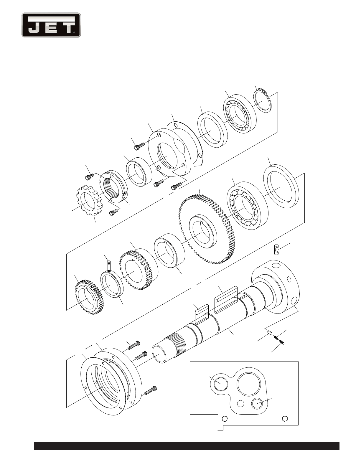
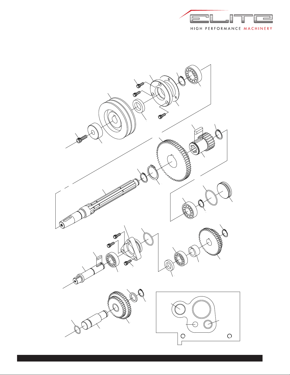
GEARBOX ASSEMBLY
29
E-1236VS
GEARBOX ASSEMBLY
A
B
C
D
A
B
48
49
50
51
22
23
24
25
26
27
28
29
30
31
32
33
34
35
37
38
36
39
40
41
42
43
44
45
46
47
43
23
30
1236 Lathe
C
D
A B
C D
53
54
55
26
56
57
58
59
60
61
26
62
63
64
65
66
67
68
69
70
71
72
73
23
23
59
GEARBOX ASSEMBLY

31
E-1236VS
GEARBOX ASSEMBLY PARTS LIST
Index No. Parts No. Description Size Qty.
1 EBL1236VS-B01 Gear Box 1
2 EBL1236VS-B02 Gasket For Gearbox
42001
1
3 EBL1236VS-B03 Gear Box Cover 1
4 EBL1236VS-B04 Gasket For Gearbox
Cover42002
1
5 EBL1236VS-B05 Index Plate 3
6 TS-1524011 Set Screw M8x8L 3
7 EBL1236VS-B07 Spring 1/4 in × 27mm 3
8 SB-1/4 Ball Steel 1/4 in. dia 3
9 EBL1236VS-B09 Handle Ø45*35L 2
10 EBL1236VS-B10 Lever 2
11 EBL1236VS-B11 Handle 2
12 EBL1236VS-B12 Pin Ø5×40mm 2
13 EBL1236VS-B13 Lever 2
14 EBL1236VS-B14 Oil Seal TC 16×26×7mm 2
15 EBL1236VS-B15 Shift Lever 2
16 EBL1236VS-B16 Shift Fork 1
17 EBL1236VS-B17 Shift Fork 1
18 EBL1236VS-B18 Gear Box Plate 1
19 TS-1503061 Socket Head Cap Screw M6×25mm 8
20 TS-1504131 Socket Head Cap Screw M8X70mm 3
21 EBL1236VS-B21 Oil Sight 1-1/8 in.(28mm.) 1
22 EBL1236VS-B22 Oil Seal TC 22×35×7mm 1
23 TS-1503041 Socket Head Cap Screw M6X16mm 11
24 EBL1236VS-B24 Cover 1
25 EBL1236VS-B25 Gasket For 42012 1
26 BB-6003 Bearing No.6003 3
27 EBL1236VS-B27 Circlip S-16mm 1
28 EBL1236VS-B28 Collar 1
29 EBL1236VS-B29 Shift 1
30 EBL1236VS-B30 Key 5×55mm 1
31 EBL1236VS-B31 Gear 2M 32T 1
32 EBL1236VS-B32 Gear 2M 16T 1
33 EBL1236VS-B33 Collar 1
34 EBL1236VS-B34 Gear 2M 24T 1
35 EBL1236VS-B35 Collar LFB-1615 1
36 EBL1236VS-B36 Gear 2M 30T 1
37 EBL1236VS-B37 Gear 2.75M 20T 1
38 EBL1236VS-B38 Gear 2.75M 18T 1
39 EBL1236VS-B39 Gear 2.75M 16T 1
40 EBL1236VS-B40 Gear 2.25M 28T 1

32
1236 Lathe
Index No. Parts No. Description Size Qty.
41 EBL1236VS-B41 Gear 2M 16T 1
42 EBL1236VS-B42 Nut 2
43 BB-51104 Thrust Bearing No.51104 2
44 EBL1236VS-B44 Collar LFB-2010 1
45 EBL1236VS-B45 Gasket For 42045 1
46 EBL1236VS-B46 Cover 1
47 EBL1236VS-B47 Key 5×70mm 1
48 EBL1236VS-B48 Gear 1
49 EBL1236VS-B49 Shaft 1
50 EBL1236VS-B50 Shaft 1
51 EBL1236VS-B51 Clutch 1
52 EBL1236VS-B52 Handle 1
53 EBL1236VS-B53 Cover 1
54 EBL1236VS-B54 Gasket For 2205 1
55 EBL1236VS-B55 Gear 2M 2T 1
56 EBL1236VS-B56 Key 5×15mm 1
57 EBL1236VS-B57 Gear 2M 40T 1
58 EBL1236VS-B58 Gear 2M 30T 1
59 EBL1236VS-B59 Circlip S-30 2
60 EBL1236VS-B60 Shaft 1
61 EBL1236VS-B61 Gear 2M 25T 1
62 EBL1236VS-B62 Gear 2.75M 20T 1
63 EBL1236VS-B63 Gear 2.25M 20T 1
64 EBL1236VS-B64 Key 5×20mm 1
65 EBL1236VS-B65 Circlip S-20mm 1
66 EBL1236VS-B66 Gear 2M 38T 1
67 EBL1236VS-B67 Gasket For 42032 1
68 EBL1236VS-B68 Collar LFB-2020 1
69 EBL1236VS-B69 Cover 1
70 EBL1236VS-B70 Oil Seal TC 20x30x8mm 1
71 EBL1236VS-B71 Collar LFB-1208 1
72 EBL1236VS-B72 Key 5×12mm 1
73 EBL1236VS-B73 Shaft 1
33
E-1236VS
L
H
F
C
B
A
D
E
H
L
2
1
3
4
5
6
7
8
9
10
11
12
13
14
7
8
15
16
17
18
19
20
21
22
23
24
25
26
27
28
29
30
31
32
19
APRON ASSEMBLY (CASTING)
34
1236 Lathe
APRON ASSEMBLY (CASTING)
F
C
B
A
D
E
H
L
OIL
A
B
C
E
33
34
35
36
37
13
15
38
39
40
41
42
43
44
45
13
46
47
48
49
50
51
52
53
54
55
35
E-1236VS
L
M
H
N
F
E
D
C
B
A
N
M
D
72
73
74
62
63
64
65
66
67
68
69
70
71
4
15
56
54
43
57
58
27
59
60
61
43
68
APRON ASSEMBLY (CASTING)

36
1236 Lathe
APRON ASSEMBLY (CASTING) PARTS LIST
Index No. Parts No. Description Size Qty.
1 EBL1236VS-C01 Walnut 8TPI 1
2 EBL1236VS-C02 Walnut Bracket 105L*50W*71h 1
3 TS-1503021 Socket Head Cap Screw M6×10mm 2
4 TS-1503051 Socket Head Cap Screw M6×20mm 6
5 TS-1523031 Set Screw M6×10mm 3
6 EBL1236VS-C06 Gib 13.8W*10H*125L 1
7 EBL1236VS-C07 Circlip S-30mm 2
8 EBL1236VS-C08 Collar Ø38.1*Ø31*3t 2
9 EBL1236VS-C09 Worm Ø19.05*Ø31*841L 1
10 EBL1236VS-C10 Pin 3×8 mm 2
EBL1236VS-C08A
Collar Assembly
(Including #8~10)
1
11 EBL1236VS-C11 Key 5×25mm 1
12 EBL1236VS-C12 Shaft Ø39.9*61L 1
13 SB-1/4 Ball Steel 1/4 in. dia 4
14 EBL1236VS-C14 Spring 1/4 in × 25mm 1
15 TS-1524011 Set Screw M8×8mm 3
16 EBL1236VS-C16 Lever 62L*36W*17H 1
17 EBL1236VS-C17 Pin Ø5×36mm 1
18 EBL1236VS-C18 Pin Ø5×60mm 1
19 EBL1236VS-C19 Handle 2
20 EBL1236VS-C20 Lever Ø1/2”*107L 1
21 EBL1236VS-C21 Handle Ø50*30L Ø16 1
22 TS-1504071 Socket Head Cap Screw M8×35mm 2
23 EBL1236VS-C23 Apron 276L*78W*172H 1
24 EBL1236VS-C24 Plug 3/8 G.P 1
25 EBL1236VS-C25 Oil Sight 3/4 in. (19mm.) 1
26 EBL1236VS-C26 Cam 50*30*12H 1
27 TS-1503031 Socket Head Cap Screw M6×12mm 2
28 EBL1236VS-C28 Plug Ø28*8W 1
29 EBL1236VS-C29 Keep Assy 65L*50W*35H 1
30 TS-1503081 Socket Head Cap Screw M6×35mm 3
31 EBL1236VS-C31 Gear Shaft Ø24*67L 1
32 EBL1236VS-C32 Lever Ø1/2”*80L 1
33 EBL1236VS-C33 Shaft Ø16*77L 1
34 EBL1236VS-C34 Collar Ø38*Ø16*30L 1
35 EBL1236VS-C35 Circlip E-15mm 1
36 EBL1236VS-C36 Shaft Ø20*122L 1
37 EBL1236VS-C37 Spring 1/4 in × 20mm 1
38 EBL1236VS-C38 Gear 2M 22/44T 1
39 EBL1236VS-C39 Circlip E-12mm 1

37
E-1236VS
Index No. Parts No. Description Size Qty.
40 EBL1236VS-C40 Plug Ø28*8W 1
41 EBL1236VS-C41 Circlip S-16mm 1
42 EBL1236VS-C42 Collar Ø25.4*Ø16*3W 1
43 EBL1236VS-C43 Pin Ø5×30mm 3
44 EBL1236VS-C44 Gear 2M 50T 1
45 EBL1236VS-C45 Rack Pinion Ø22.5*120L 1
46 TS-1523071 Set Screw M6×25mm 1
47 EBL1236VS-C47 Plug 35*15L ØM6 TAP 1
48 EBL1236VS-C48 Handle Ø5/8"*77L 1
49 EBL1236VS-C49 Hand Wheel Ø140*68H Ø17 1
50 EBL1236VS-C50 Spring 1/4 in.× 8mm 2
51 EBL1236VS-C51 Index Ring Ø63*Ø45*20W 1
52 TS-1503041 Socket Head Cap Screw M6×16mm 3
53 EBL1236VS-C53 Keep Ass'y Ø60*Ø18*57L 1
54 EBL1236VS-C54 Key 4×15mm 2
55 EBL1236VS-C55 Shaft Ø28*108L key4*2 1
56 EBL1236VS-C56 O-Ring P14 1
57 EBL1236VS-C57 Shaft 1
58 EBL1236VS-C58 Gear 1
59 EBL1236VS-C59 Gear 1
60 EBL1236VS-C60 Worm Gear Ø30*Ø14*23L 1
61 EBL1236VS-C61 Washer Ø25*Ø1/4"*3t 1
62 EBL1236VS-C62 Shaft 1
63 EBL1236VS-C63 Keep Ass'y 1
64 EBL1236VS-C64 Spring 1/4 in.× 10mm 1
65 EBL1236VS-C65 O-Ring 3.5x34.7x41.7 1
66 EBL1236VS-C66 O-Ring 3.5x28.7x35.7 1
67 EBL1236VS-C67 Oil Seal TC 20x30x8mm 1
68 EBL1236VS-C68 Circlip S-20mm 2
69 EBL1236VS-C69 Collar 1
70 EBL1236VS-C70 Gear 1
71 EBL1236VS-C71 Collar LFB-2012 1
72 EBL1236VS-C72 Plug 1
73 EBL1236VS-C73 O-Ring Ø2.4xØ21.8xØ26.6 1
74 EBL1236VS-C74 Gear Shaft 1
38
1236 Lathe
OIL
1
1
2
3
4
5
6
7
8
9
10
11
12
7
7
7
7
7
13
14
15
16
17
18
19
20
22
23
25
26
27
28
29
30
31
32
33
34
35
37
36
20
21
13
24
25
5
5
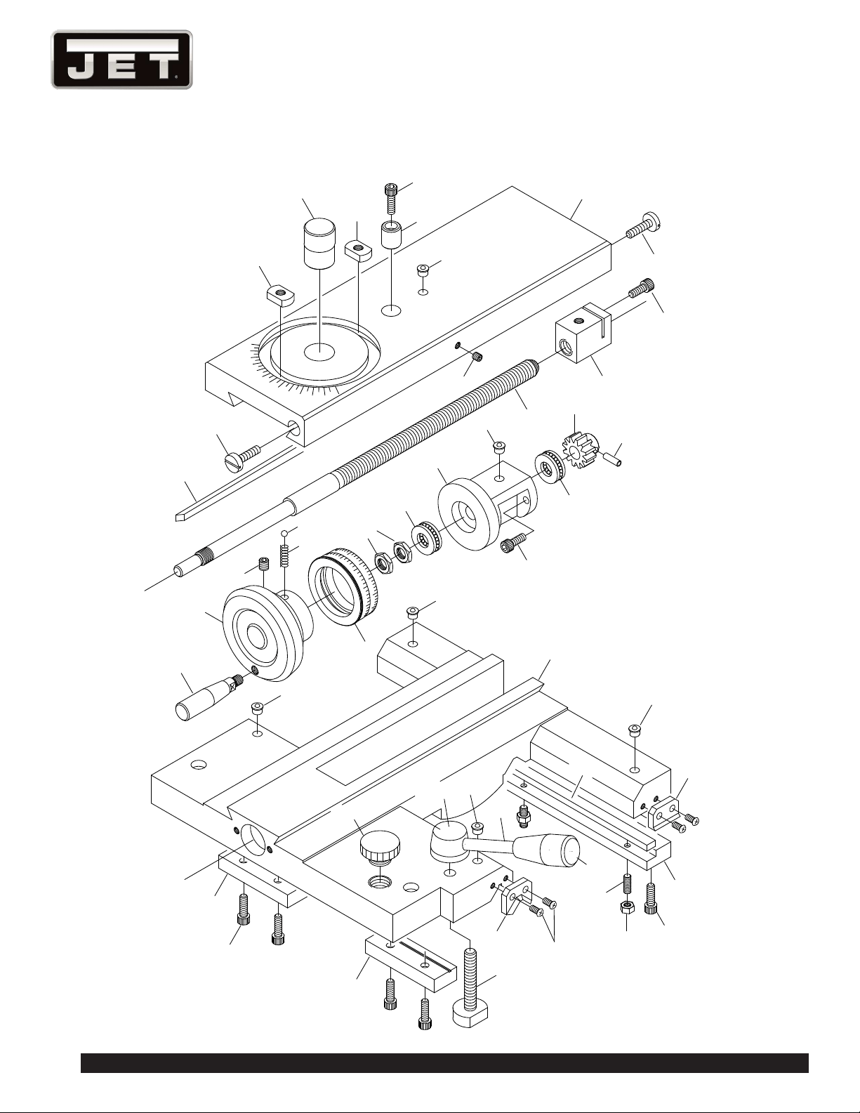
CARRIAGE ASSEMBLY

39
E-1236VS
CARRIAGE ASSEMBLY PARTS LIST
Index No. Parts No. Description Size Qty.
1 EBL1236VS-D01 Gib Screw Ø5/8"*30L 2
2 EBL1236VS-D02 Gib 15*22*410 355L 1
3 EBL1236VS-D03 Nut Ø7/8"*14W*6.5T 2
4 EBL1236VS-D04 Pirot Ø25.4*35L 1
5 TS-1503051 Socket Head Cap Screw M6×20mm 8
6 EBL1236VS-D06 Collar Ø16*18.5L 1
7 EBL1236VS-D07 Oiler 5/16 in 2
8 EBL1236VS-D08 Cross Slide Cover 115W*355L*29H 1
9 TS-1523011 Set Screw M6×6mm 1
10 EBL1236VS-D10 Screw Ø5/8"*404L 1
11 EBL1236VS-D11 Nut 24W*40L*29H 1
12 TS-1503041 Socket Head Cap Screw M6×16mm 1
EBL1236VS-D10A Screw Assembly (Includ-
ing #10~12)
1
13 EBL1236VS-D13 Handle Ø5/8"*68L 1
14 EBL1236VS-D14 Hand Wheel Ø85*45L Ø10 1
15 TS-1524011 Set Screw M8×8mm 1
16 SB-1/4 Ball Steel 1/4 in. dia 3
17 EBL1236VS-D17 Spring 1/4 in.× 8mm 1
18 EBL1236VS-D18 Index Ring Ø61.5~Ø60 Ø45*200L 1
19 TS-1540081 Nut M12*PC1.25 4T 2
20 BB-51101 Thrust Bearing No.51101 2
21 EBL1236VS-D21 Keep Ass'y Ø60*Ø12*66L 1
22 EBL1236VS-D22 Gear Ø27.9*Ø12*20L 1
23 EBL1236VS-D23 Pin Ø5×16mm 1
24 EBL1236VS-D24 Saddle Casting 295W*307L 1
25 EBL1236VS-D25 Strip 80L*26W*13T 2
26 EBL1236VS-D26 Set Screw Ø9/8"*67L 1
27 EBL1236VS-D27 Handle 3/8 in. 1
28 EBL1236VS-D28 Lever 1
29 EBL1236VS-D29 Handle 1
30 EBL1236VS-D30 Plug 3/4 in.(P.V.C) 1
31 EBL1236VS-D31 Wiper 2
32 EBL1236VS-D32 Wiper 2
33 EBL1236VS-D33 Screw 3/16×3/8 in 13
34 EBL1236VS-D34 Gib 295L*10W*6T 1
35 EBL1236VS-D35 Strip 295L*28W*15h 1
36 TS-1523051 Set Screw M6×16mm 3
37 TS-1540041 Nut M6 3
40
1236 Lathe
1
2
3
4
5
6
7
8
9
10
11
12
13
14
15
16
17
18
19
21
22
23
24
25
26
27
28
29
30
31
32
6
20
30
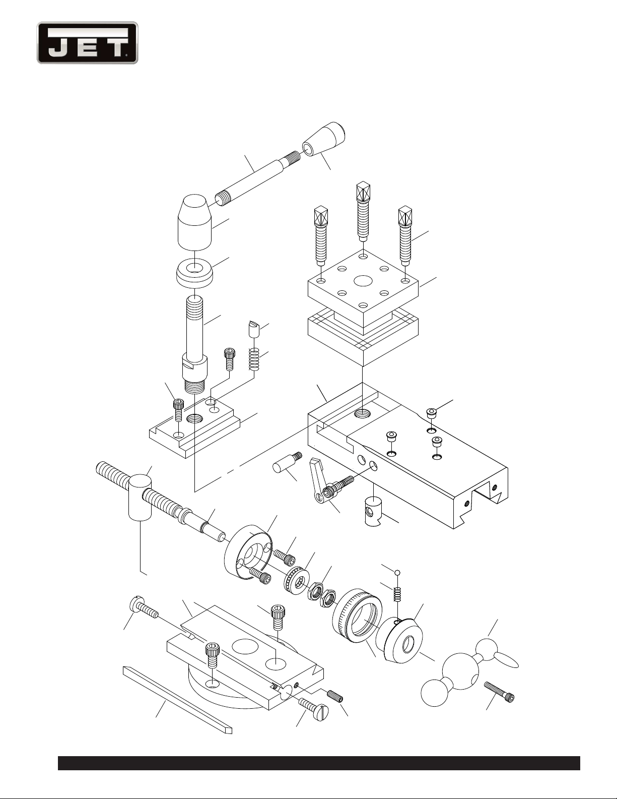
TOOLPOST ASSEMBLY

41
E-1236VS
TOOLPOST ASSEMBLY PARTS LIST
Index No. Parts No. Description Size Qty.
1 EBL1236VS-E01 Handle 3/8 in. 1
2 EBL1236VS-E02 Lever Ø1/2"*107L 1
3 EBL1236VS-E03 Tool Post ~12" 62H 1
4 EBL1236VS-E04 Washer Ø35*Ø16*12h 1
5 EBL1236VS-E05 Bolt Ø24*106.5L 1
6 TS-1503041 Socket Head Cap Screw M6×16mm 4
7 EBL1236VS-E07 T Nut 1
8 EBL1236VS-E08 Pad Ø3/8"*15L 1
9 EBL1236VS-E09 Spring 3/8 in × 20mm 1
10 EBL1236VS-E10 Top Slide 200L*75W*37W 1
11 EBL1236VS-E11 Screw Ø12.7*65 8
12 EBL1236VS-E12 Tool Post 1
13 EBL1236VS-E13 Oiler 5/16 in 3
14 EBL1236VS-E14 Pin 1
15 EBL1236VS-E15 Handle 1
16 EBL1236VS-E16 Pad Ø16*24L 1
17 EBL1236VS-E17 Nut Ø20*40L 1
18 EBL1236VS-E18 Screw Ø15.8*170L 1
EBL1236VS-E17A
Nut Assembly (Including
#17~18)
1
19 EBL1236VS-E19 Keep Ass'y Ø52.5*Ø12*15L 1
20 BB-51101 Thrust No.51101 2
21 TS-1540083 Nut M12*PC1.25 4T 2
22 EBL1236VS-E22 Index Ring Ø49.5~Ø48*Ø20L 1
23 SB-1/4 Ball Steel 1/4 in. dia 1
24 EBL1236VS-E24 Spring 1/4 in.× 8mm 1
25 EBL1236VS-E25 Keep Ass'y 1
26 EBL1236VS-E26 Three Ball Handle 1
27 TS-1503071 Socket Head Cap Screw M6×30mm 1
28 EBL1236VS-E28 Swiveled Slide 11" 26 12"35 13"43 1
29 TS-1504031 Socket Head Cap Screw M8×16mm 2
30 EBL1236VS-E30 Gib Screw 5/8"*30L 2
31 TS-1523051 Set Screw M6×16mm 1
32 EBL1236VS-E32 Gib 140L 12*20*190 1
42
1236 Lathe
1
2
3
4
5
6
7
8
9
10
11
12
13
15
16
17
18
19
20
22
21
23
26
27
28
29
30
31
32
2
8
13
14
23
24
23
11
25
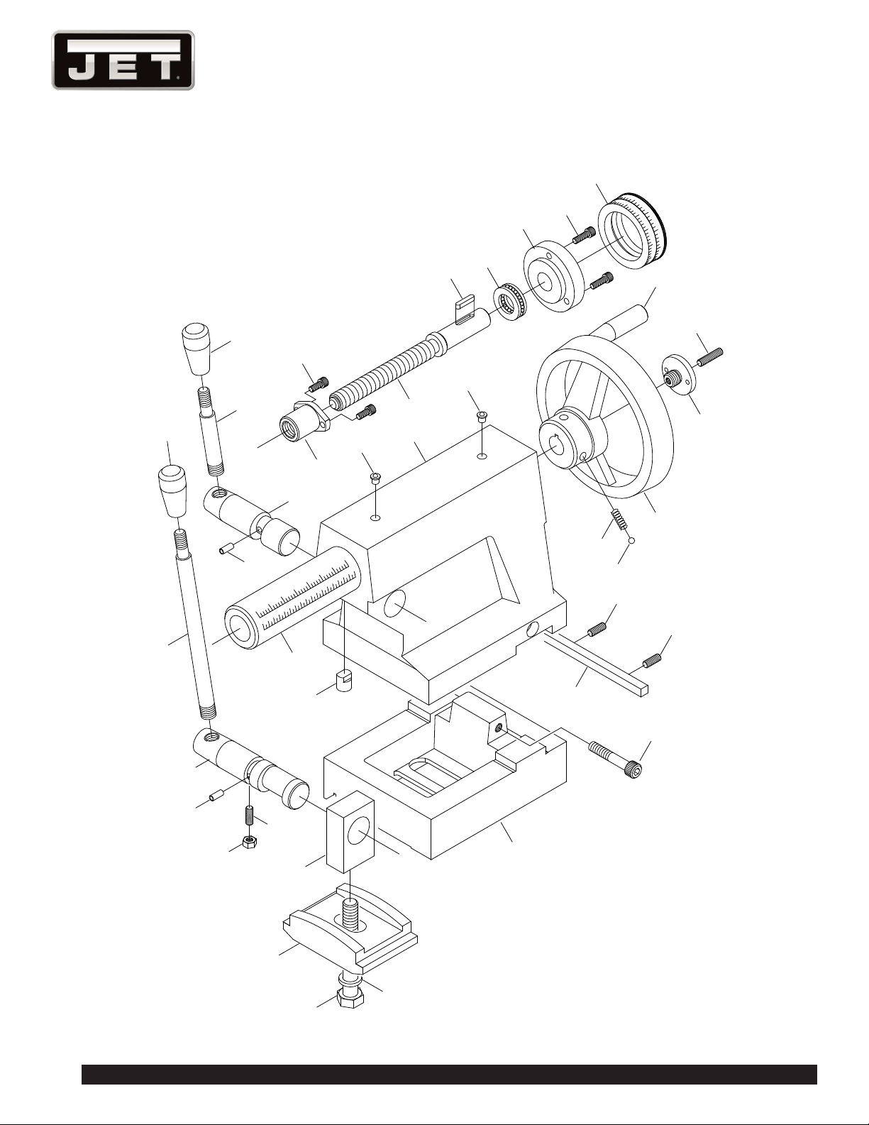
TAILSTOCK ASSEMBLY

43
E-1236VS
TAILSTOCK ASSEMBLY PARTS LIST
Index No. Parts No. Description Size Qty.
1 EBL1236VS-F01 Nut 30L 1
2 TS-1502041 Socket Head Cap Screw M5×16mm 4
3 EBL1236VS-F03 Screw Ø20.5*179L 1
EBL1236VS-F01A
Nut Assembly (Including
#1~3)
1
4 EBL1236VS-F04 Key 4×20mm 1
5 BB-51102 Thrust No.51102 1
6 EBL1236VS-F06 Keep Ass'y Ø17*Ø60*17L 1
7 EBL1236VS-F07 Index Ring Ø61.5~Ø60*Ø45*20W 1
8 EBL1236VS-F08 Handle 3/8 in. 1
9 EBL1236VS-F09 Lever 1
10 EBL1236VS-F10 Shaft Ø25*Ø16*91L 1
11 EBL1236VS-F11 Pin Ø5×12mm 1
12 EBL1236VS-F12 Barrel 2 Ø40*190L 1
13 EBL1236VS-F13 Oiler 5/16 in 2
14 EBL1236VS-F14 Tall stock Casting 2 Ø40 125h 1
15 EBL1236VS-F15 Spring 1/4 in × 20mm 2
16 SB-1/4 Ball Steel 1/4 in. dia 2
17 EBL1236VS-F17 Screw Ø35*16L 1
18 EBL1236VS-F18 Handle Wheel Ø140*68h 1
19 EBL1236VS-F19 Handle Ø5/8"*77L 1
20 TS-1523071 Set Screw M6×25mm 1
21 EBL1236VS-F21 Lever Ø1/2"*190 1
22 EBL1236VS-F22 Shaft Ø25*Ø18*114L 1
23 TS-1523051 Set Screw M6×16mm 1
24 TS-1540041 Nut M6 1
25 EBL1236VS-F25 Pad 2 Ø1/2"*14L 1
26 EBL1236VS-F26 Pirot Block 36L*20W*57H 1
27 EBL1236VS-F27 Base ~1 28h 1
28 TS-1504091 Socket Head Cap Screw M8×45mm 2
29 EBL1236VS-F29 Gib 8*8*125 1
30 EBL1236VS-F30 Clamp Plate 65W*94L*28H 1
31 TS-0680061 Washer 1/2 in 1
32 TS-0070051 Cap Screw 1/2×2 in 1
44
1236 Lathe
A
B
C
A
B
1
2
3
4
5
6
7
8
9
10
11
12
13
14
15
16
17
19
20
21
22
23
24
25
26
27
28
29
30
31
32
33
34
35
36
37
16
16
18
16
38
39
40
BED ASSEMBLY

45
E-1236VS
BED ASSEMBLY PARTS LIST
Index No. Parts No. Description Size Qty.
1 EBL1236VS-G01 Gap 240*190*70 1
2 TS-1505051 Socket Head Cap Screw M10×35mm 2
3 EBL1236VS-G03 Taper Pin Ø4×38mm 2
4 EBL1236VS-G04 Bed Casting 36"-1525 1
5 TS-0050031 Hex Cap Screw 1/2×1-3/4 in 6
6 EBL1236VS-G06 Rack 36" 990L 1
7 TS-1503051 Socket Head Cap Screw M6×20mm 4
8 EBL1236VS-G08 Pin Ø5×30mm 8
9 EBL1236VS-G09 Pin 1
10 EBL1236VS-G10 Lead screw 36" 1250L 1
11 EBL1236VS-G11 Feed Shaft 36" 1268L 1
12 EBL1236VS-G12 Third-Rod Shaft 1
13 EBL1236VS-G13 Key 5×60mm 1
14 EBL1236VS-G14 Pin Ø3×8 mm 2
15 EBL1236VS-G15 Sleeve Ø38*Ø19.05*60L 1
16 TS-1524011 Set Screw M8×8mm 3
17 EBL1236VS-G17 Spring 1/4 in × 35mm 1
18 EBL1236VS-G18 Pin Ø6.3*19L 1
19 EBL1236VS-G19 Bracket Ø54 1
20 TS-1503041 Socket Head Cap Screw M6×16mm 2
21 TS-1540041 Nut M6 2
22 TS-1523051 Set Screw M6×16mm 2
23 EBL1236VS-G23 Fork Ø51*20 1
24 EBL1236VS-G24 Lever Ø3/8" *220L 1
25 EBL1236VS-G25 Handle 3/8 in. 1
26 EBL1236VS-G26 Pin Ø3×20mm 1
27 EBL1236VS-G27 Collar Ø38*Ø19.05**12L 1
28 EBL1236VS-G28 Base 1
29 EBL1236VS-G29 Pin Ø5×40mm 1
30 TS-1504131 Socket Head Cap Screw M8×70mm 1
31 TS-1504101 Socket Head Cap Screw M8×50mm 1
32 EBL1236VS-G32 Pin Ø5×50mm 1
33 EBL1236VS-G33 Box 115L*80W*48h 1
34 EBL1236VS-G34 Pin Ø5×35mm 2
35 TS-1503031 Socket Head Cap Screw M6×12mm 1
36 EBL1236VS-G36 Collar Ø44*Ø19.5*30W 1
37 SB-1/4 Ball Steel 1/4 in. dia 1
38 EBL1236VS-G38 Spring 1/4 in × 30mm 1
39 EBL1236VS-G39 Cover 1
40 EBL1236VS-G40 Limit Switch 2
46
1236 Lathe
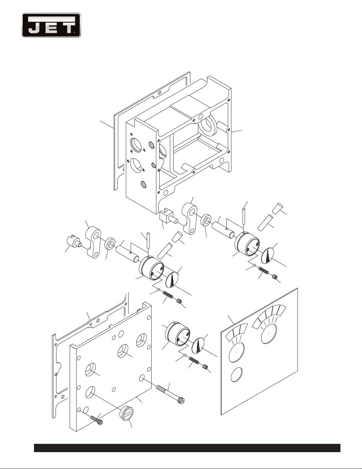
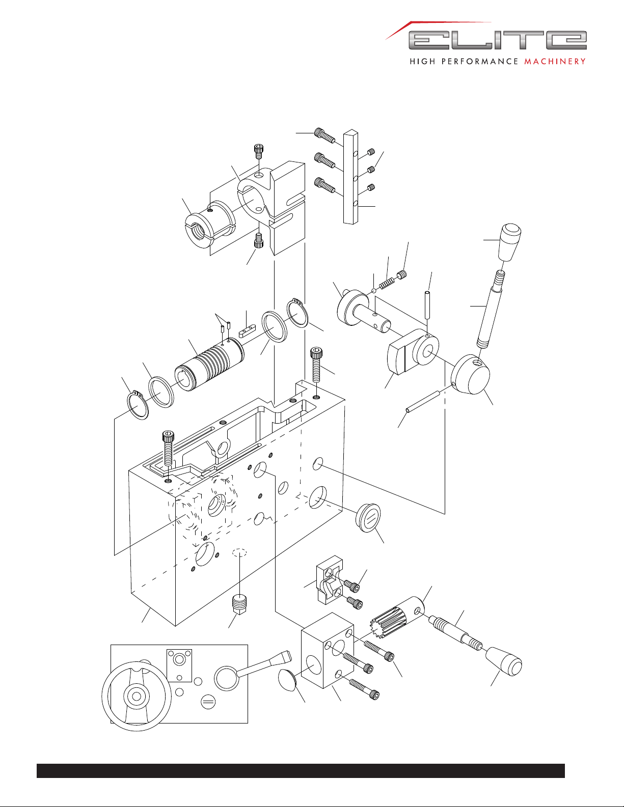
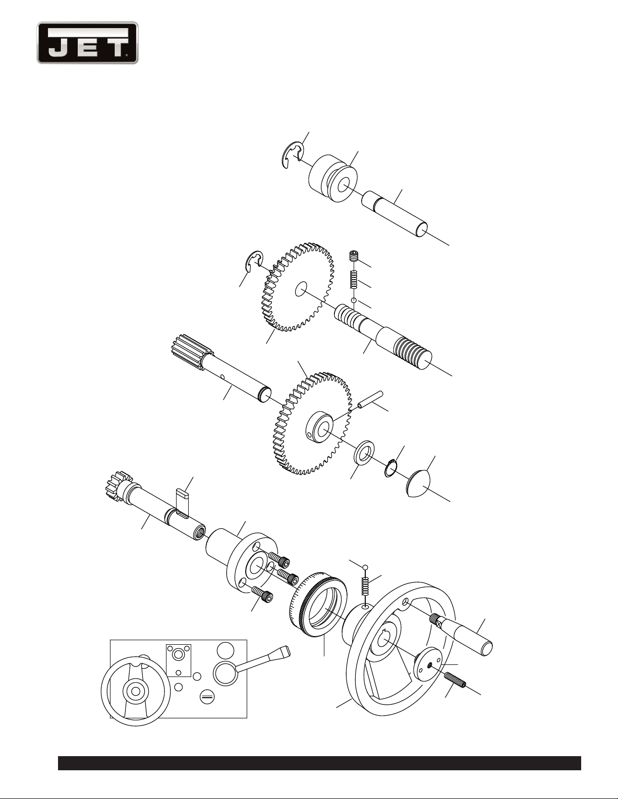
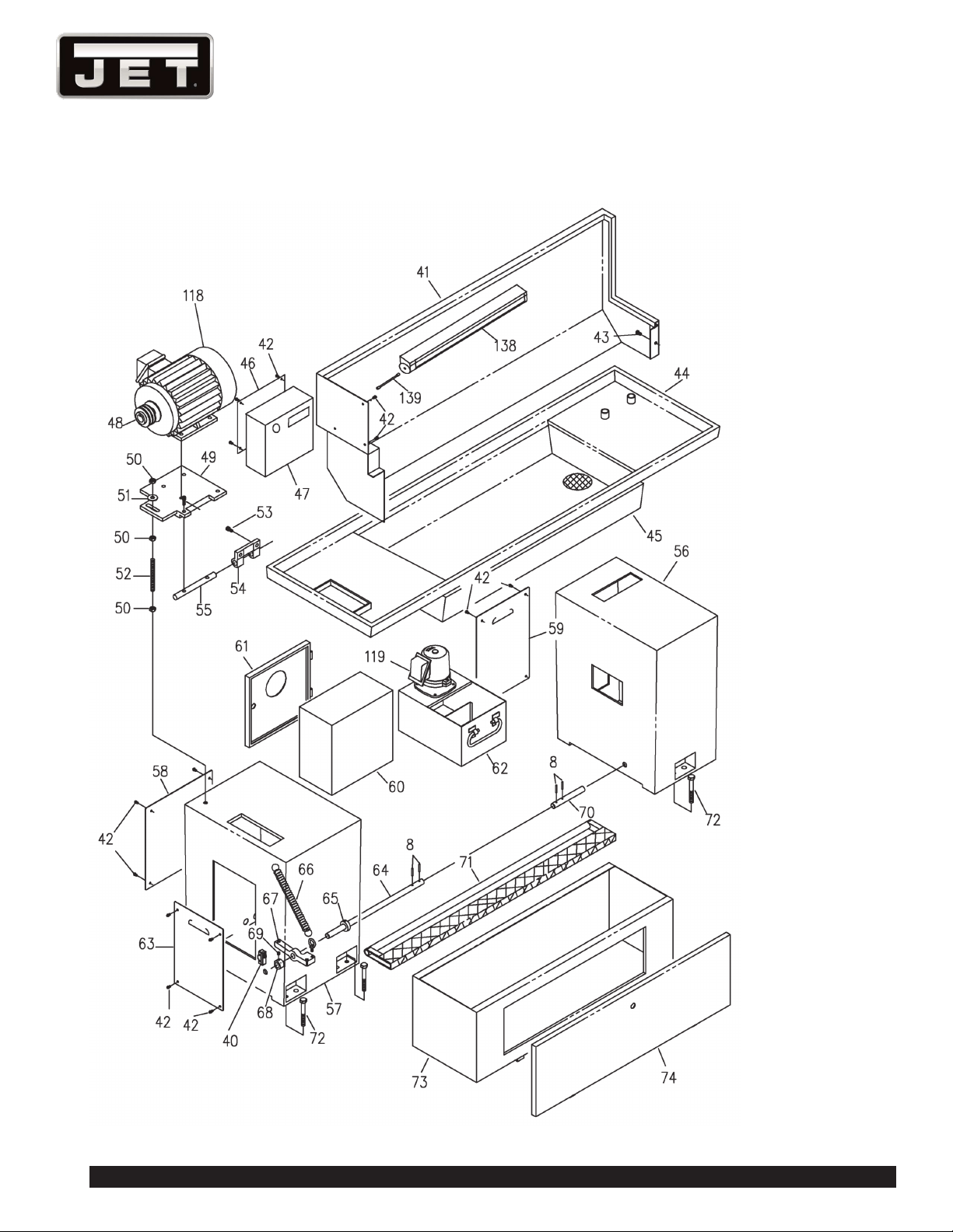
CABINET AND PANEL ASSEMBLY

47
E-1236VS
CABINET AND PANEL ASSEMBLY PARTS LIST
Index No. Parts No. Description Size Qty.
41 EBL1236VS-G41 Splash Guard 1
42 TS-0254011 Screw 1/4×3/8 in 19
43 EBL1236VS-G43 Cap Screw 1/4x1-1/4 in 1
44 EBL1236VS-G44 Chip Pan 1
45 EBL1236VS-G45 Chip Tray 1
46 EBL1236VS-G46 Guard 1
47 EBL1236VS-G47 Cover 1
48 EBL1236VS-G48 Pulley 1
49 EBL1236VS-G49 Motor Platform 275*220W*1/2"T(12.7mm) 1
50 TS-0561051 Nut 1/2 in 3
51 TS-0680061 Washer 1/2 in 1
52 TS-0273121 Socket Hex Set Screw 1/2×3 in 1
53 TS-1504041 Socket Head Cap Screw M8×20mm 2
54 EBL1236VS-G54 Bracket 109L*65W 1
55 EBL1236VS-G55 Shaft Ø3/4"*170L 1
56 EBL1236VS-G56 Floor Stand 500W*300L*620H 1
57 EBL1236VS-G57 Floor Stand 437L*368W*15H 1
58 EBL1236VS-G58 Cover 350L*330W*1.6T 1
59 EBL1236VS-G59 Cover 390L*260W*1.6T 1
60 EBL1236VS-G60 Electric Box 300*300*178 1.2T 1
61 EBL1236VS-G61 Cover 300*300*20*1.2T 1
EBL1236VS-G60A
Electric Box Assembly
(Including #60~61)
1
62 EBL1236VS-G62 Coolant Tank 310L*220W*170H 1
63 EBL1236VS-G63 Cover 350L*240W*1.6T 1
64 EBL1236VS-G64 Shaft 1
65 EBL1236VS-G65 Collar 1
66 EBL1236VS-G66 Spring 1
67 EBL1236VS-G67 Bolt 1
68 EBL1236VS-G68 Collar 1
69 TS-1524011 Set Screw M8x8mm 1
70 EBL1236VS-G70 Shaft 1
71 EBL1236VS-G71 Brake Pad 1
72 TS-0100041 Cap Screw 1/2×1/4 in 6
73 EBL1236VS-G73 Cabinet 1
74 EBL1236VS-G74 Front Cover 1
EBL1236VS-G73A
Cabinet Assembly (In-
cluding #73~74)
1
118 EBL1236VS-G118 Main motor 2HP 3PH 230V 1
119 EBL1236VS-G119 Pump 1
138 EBL1236VS-G138 Work lamp AC24V 9W 0.5m/500Lux 1
139 EBL1236VS-G139 Piple 115mm 1
48
1236 Lathe
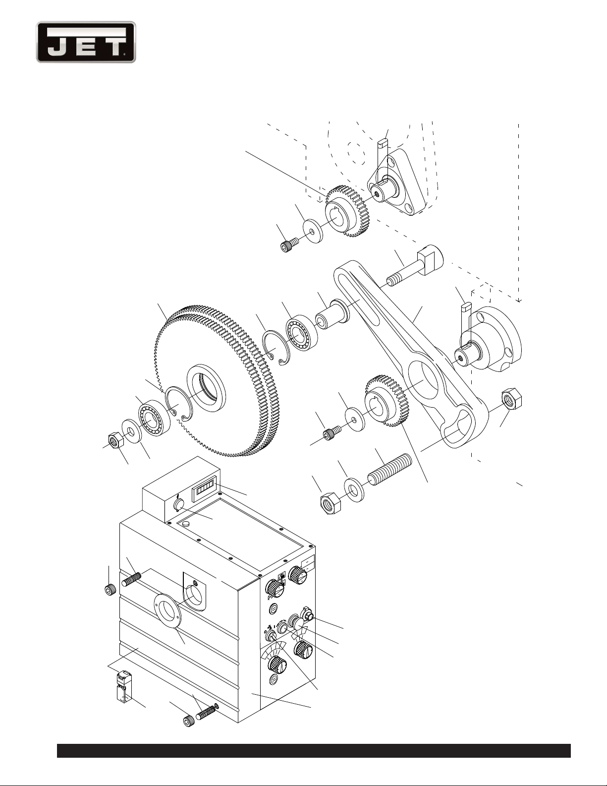
Headstock
Gearbox
75
76
77
78
79
80
81
82
83
84
85
86
89
90
91
92
93
95
96
97
98
99
100
94
35
50
81
80
35
87
77
50
88
93
101
20008
36540
B
C
A
5
1
2
3
4
OIL
L
H
L
H
END GEAR ASSEMBLY

49
E-1236VS
END GEAR ASSEMBLY PARTS LIST
Index No. Parts No. Description Size Qty.
35 TS-1503031 Socket Head Cap Screw M6×12mm 2
50 TS-0561051 Nut 1/2 in 2
75 EBL1236VS-G75 Washer Ø25*Ø1/4"*3T 2
76 EBL1236VS-G76 Change Gear 1
77 EBL1236VS-G77 Key 5×12mm 2
78 TS-0561031 Nut 3/8 in 1
79 EBL1236VS-G79 Washer Ø25*Ø3/8"*2T 1
80 BB-6003Z Bearing No.6003Z 2
81 EBL1236VS-G81 Circlip R-35mm 2
82 EBL1236VS-G82 Gear 1
83 EBL1236VS-G83 Shaft Collar Ø25*Ø3/8"*29L 1
84 EBL1236VS-G84 Swing Frame 1
85 EBL1236VS-G85 Shaft Ø25*65L 1
86 EBL1236VS-G86 Washer 1
87 EBL1236VS-G87 Change Gear 1
88 EBL1236VS-G88 Washer Ø25*1/2"*3T 1
89 TS-0273101 Socket Hex Set Screw 1/2×2 in 1
90 EBL1236VS-G90 Nut 1
91 EBL1236VS-G91 Collar 1
92 EBL1236VS-G92 Nut 1
93 EBL1236VS-G93 Shaft 2
94 EBL1236VS-G94 RPM Speed Meter 1
95 EBL1236VS-G95 Pilot Light 1
96 EBL1236VS-G96 Coolant Selecting Switch 1
97 EBL1236VS-G97 Jogging Push Bottom Switch 1
98 EBL1236VS-G98 Emergency Stop Switch 1
99 EBL1236VS-G99 Variable Speed Selector 1
100 EBL1236VS-G100 Thread Chart Plate 1
101 EBL1236VS-G101 End Cover Limit Switch 1
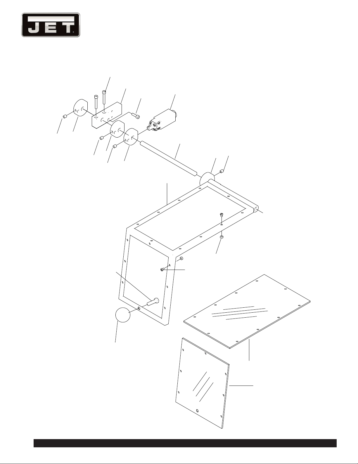
50
1236 Lathe
20
103
103
103
103
102
104
105
106
107
108
109
111
110
112
113
114
115
116
117
CHUCK SAFETY GUARD ASSEMBLY

51
E-1236VS
CHUCK SAFETY GUARD ASSEMBLY PARTS LIST
Index No. Parts No. Description Size Qty.
20 TS-1503041 Socket Head Cap Screw M6×16mm 2
102 EBL1236VS-G102 Cam 1
103 TS-1523021 Set Screw M6×8mm 4
104 EBL1236VS-G104 Keep Assy 1
105 TS-1503021 Socket Head Cap Screw M6×10mm 1
106 EBL1236VS-G106 Collar 1
107 EBL1236VS-G107 Cam 1
109 EBL1236VS-G109 Shaft 1
110 EBL1236VS-G110 Collar 1
111 EBL1236VS-G111 Chuck Guard 1
112 EBL1236VS-G112 Handle PVC 1
113 TS-1505031 Socket Head Cap Screw M10×25mm 1
114 EBL1236VS-G114 Screw 3/16×1/4 in 18
115 EBL1236VS-G115 Nut 3/16 in 18
116 EBL1236VS-G116 Window 3Tx193x343mm 1
117 EBL1236VS-G117 Window 3Tx193x230mm 1
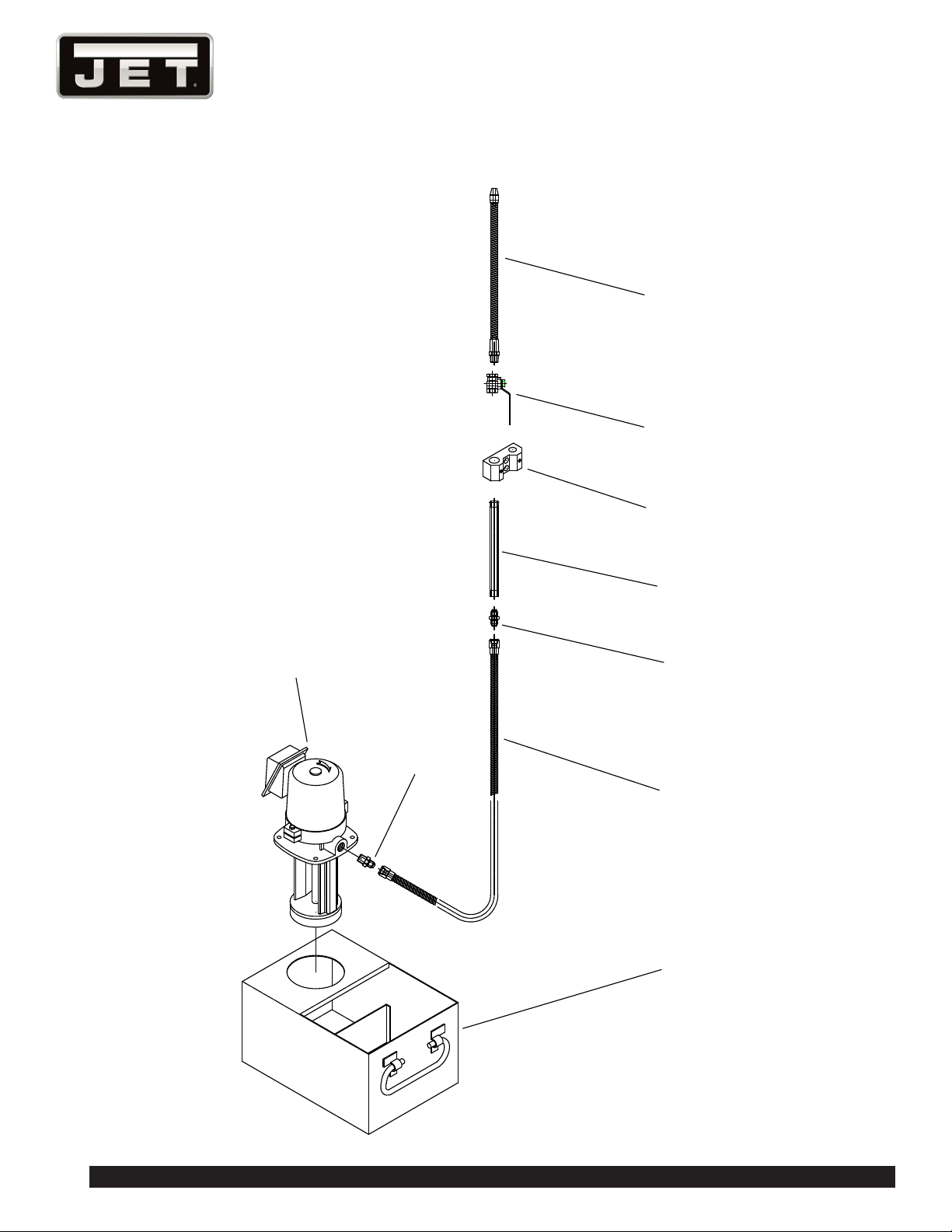
52
1236 Lathe
119
120
121
62
122
123
124
125
126
COOLANT PUMP ASSEMBLY

53
E-1236VS
COOLANT PUMP ASSEMBLY PARTS LIST
Index No. Parts No. Description Size Qty.
62 EBL1236VS-G62 Coolant Tank 310L*220W*170H 1
119 EBL1236VS-G119 Pump 1
120 EBL1236VS-G120 Nipple 1
121 EBL1236VS-G121 Flexible Hose 1
122 EBL1236VS-G122 Nipple 1
123 EBL1236VS-G123 Tube 1
124 EBL1236VS-G124 Bracket 1
125 EBL1236VS-G125 Value Gate 1
126 EBL1236VS-G126 Spraying Pipe 1
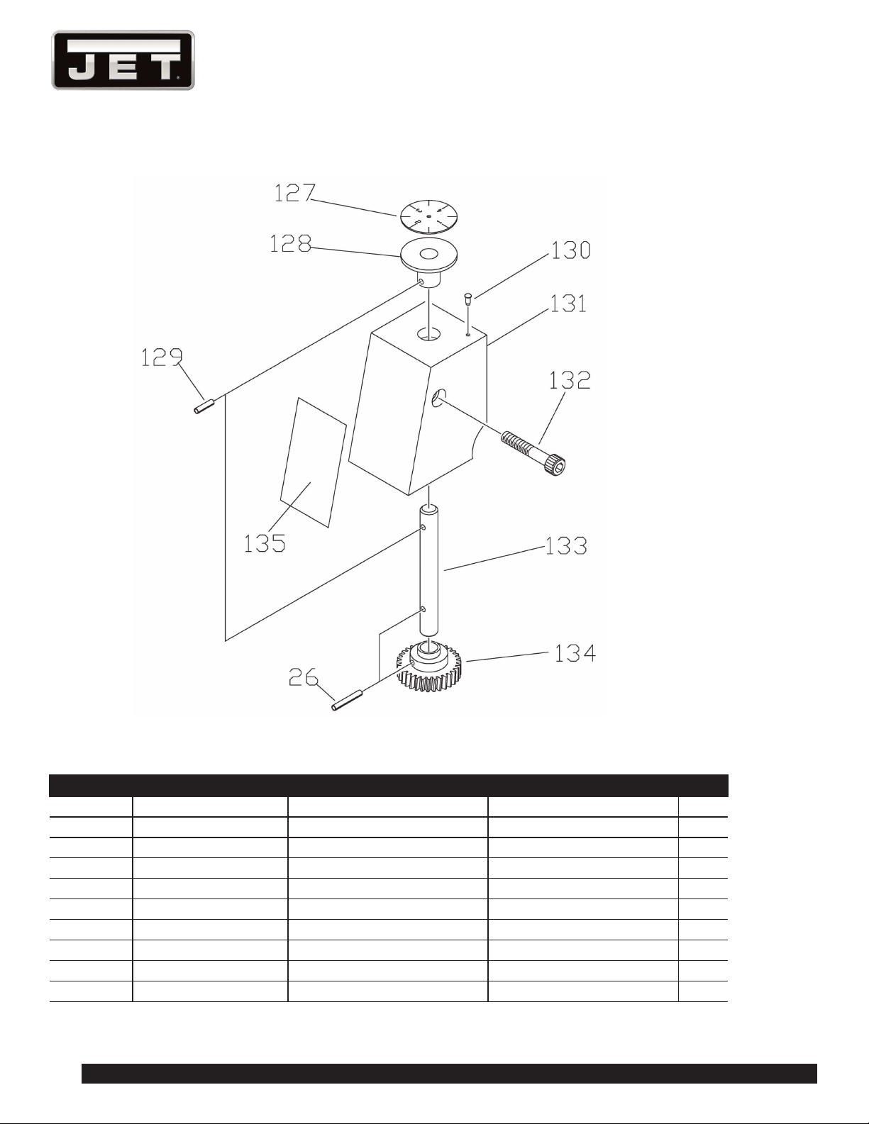
54
1236 Lathe
DIAL INDICATOR ASSEMBLY & PARTS LIST
Index No. Parts No. Description Size Qty.
26 EBL1236VS-G26 Pin Ø3×20mm 1
127 EBL1236VS-G127 Plate 1
128 EBL1236VS-G128 Dog Ø60*Ø19.05*15W 1
129 EBL1236VS-G129 Pin 3*12 mm. 1
130 EBL1236VS-G130 Nail 2 mm. 1
131 EBL1236VS-G131 Guard 75*59*45 1
132 EBL1236VS-G132 Socket Head Cap Screw M6*50mm 1
133 EBL1236VS-G133 Shaft Ø9.5*81L 1
134 EBL1236VS-G134 Gear Ø34Ø9.5*17L 1
135 EBL1236VS-G135 Threading Plate 1
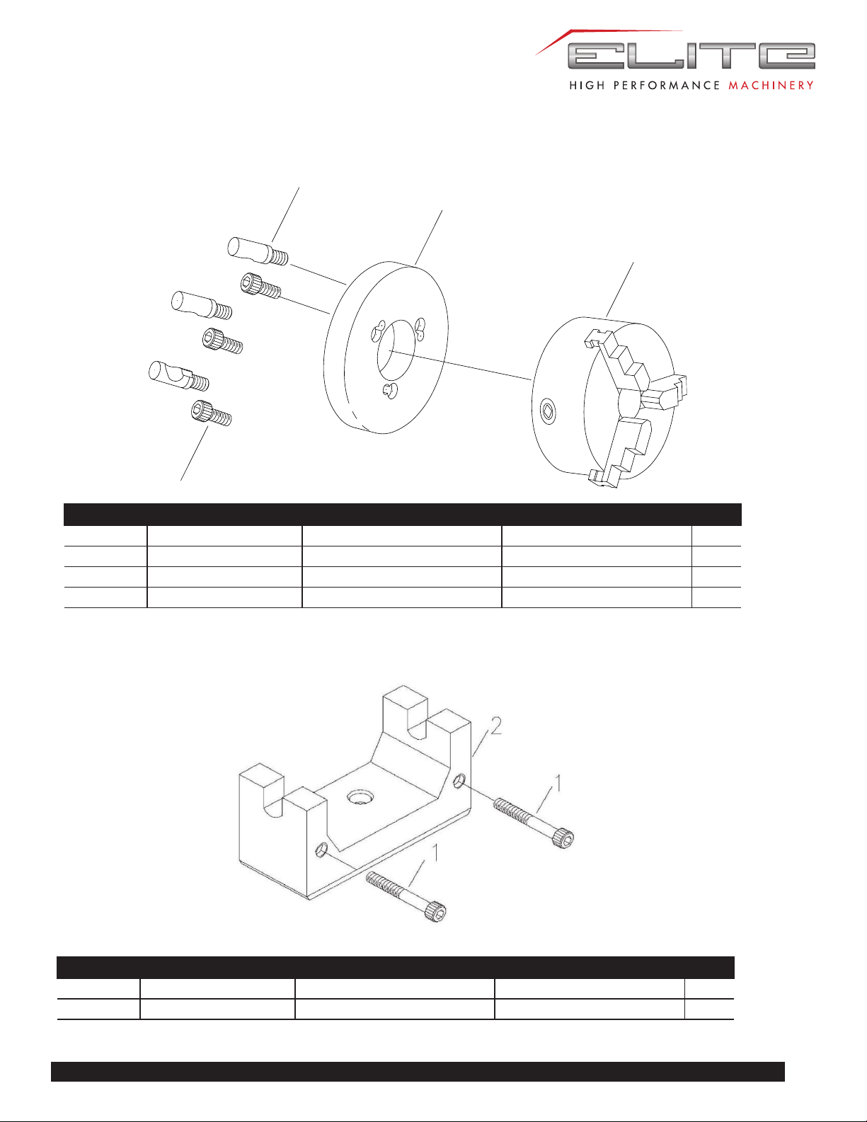
55
E-1236VS
135
137
136
7
CHUCK ASSEMBLY & PARTS LIST
Index No. Parts No. Description Size Qty.
7 TS-1503051 Socket Head Cap Screw M6×20mm 3
135 EBL1236VS-SK6 Chuck 6" 1
136 EBL1236VS-G136 Backplate 6" 1
137 EBL1236VS-G137 Stud D1-4 3
Index No. Parts No. Description Size Qty.
1 TS-1504111 Socket Head Cap Screw M8x55mm 2
2 EVS1440B-CKB Chuck Key Bracket 1
CHUCK KEY BRACKET ASSEMBLY & PARTS LIST
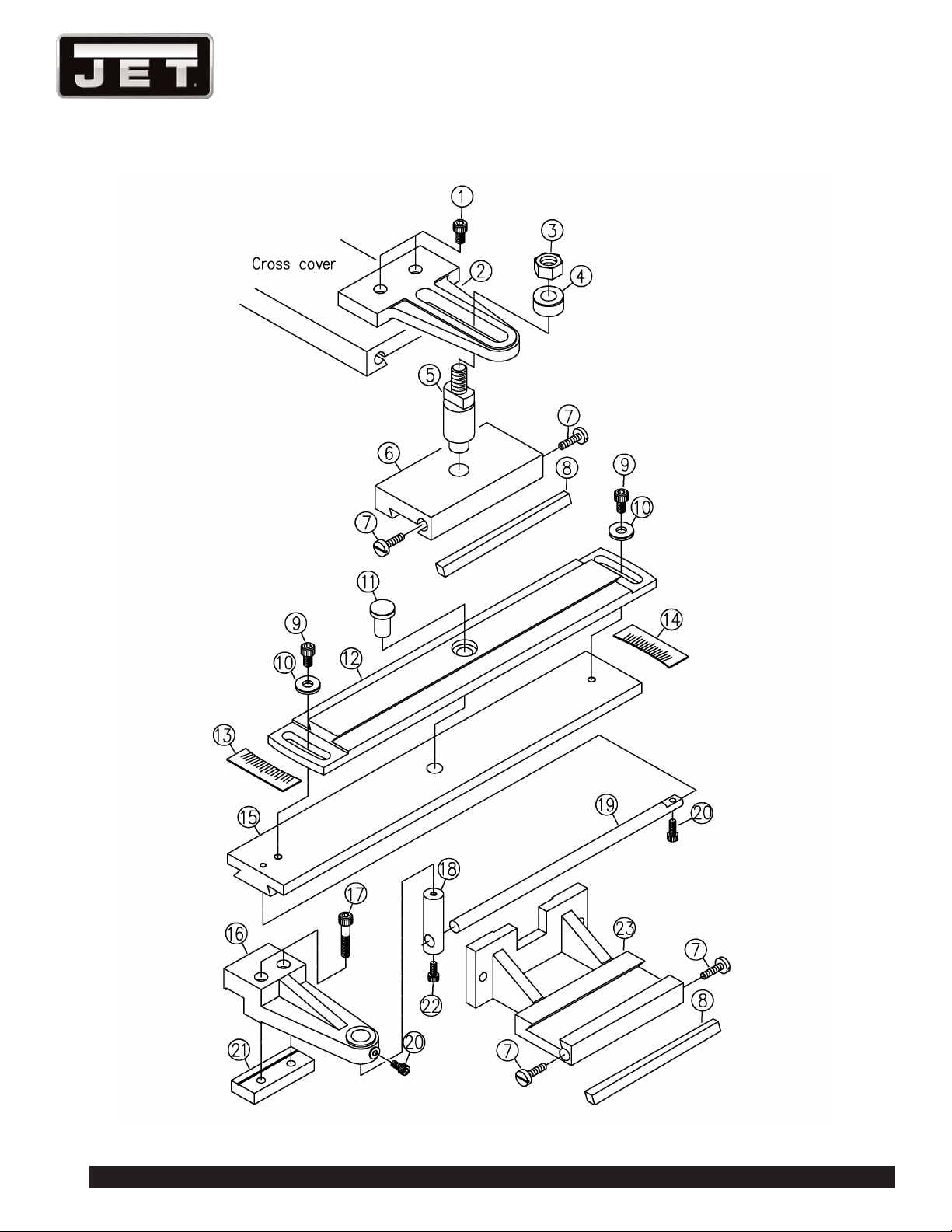
56
1236 Lathe
892005 TAPER ATTACHMENT (OPTIONAL)

57
E-1236VS
892005 TAPER ATTACHMENT (OPTIONAL) PARTS LIST
Index No. Parts No. Description Size Qty.
1 TS-1504031 Socket Head Cap Screw M8x16mm 1
2 E1236VS-J02 Trolley 160x110x16 1
3 TS-0561071 Nut 5/8"-11UNC 1
4 E1236VS-J04 Washer Ø31x13 1
5 E1236VS-J05 Shaft Ø5/8"(Ø20)x94L 1
6 E1236VS-J06 Slider 150x75x27 1
7 E1236VS-J07 Screw 4
8 E1236VS-J08 Gib 172x9.55x6.55 2
9 TS-1504041 Socket Head Cap Screw M8x20mm 2
10 E1236VS-J10 Washer Ø25x3 2
11 E1236VS-J11 Cover Ø25(Ø16)x30L 1
12 E1236VS-J12 Base 380x75x22 1
13 E1236VS-J13 Angle Scale 1
14 E1236VS-J14 Angle Scale 1
15 E1236VS-J15 Base 480x75x22 1
16 E1236VS-J16 Bracket 172.5x60x40 1
17 TS-1504091 Socket Head Cap Screw M8x45mm 1
18 E1236VS-J18 Shaft Ø3/4"x65L 1
19 E1236VS-J19 Shaft Ø1.2"x300L 1
20 TS-1503031 Socket Head Cap Screw M6x12mm 2
21 E1236VS-J21 Clamping Block 80x31x13 1
22 TS-1503021 Socket Head Cap Screw M6x10mm 1
23 E1236VS-J23 Base 145x150x71 1
892005 Taper Attachment (#1 thru 23)
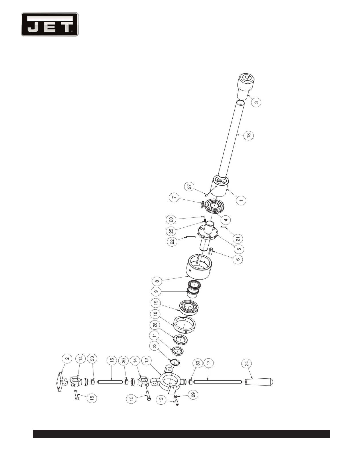
58
1236 Lathe
892006 5C COLLET CLOSER (OPTIONAL)

59
E-1236VS
892006 5C COLLET CLOSER (OPTIONAL) PARTS LIST
Index No. Parts No. Description Size Qty.
1 C510350 Sleeve Coupling 1
2 C52302004 Fixed Seat (Length) 1
3 C53004118 Sleeve #5 1
4 C54002038 Coupling 1
5 C54004047 Arbor 1
6 C54006001 Buckle 3
7 C54008007 Buckling Plate 1
8 C54012019 Outward Flange 1
9 C54014002 Bearing Shaft 1
10 C54016011 Bearing Stand 1
11 C54018020 Collar 1
12 C54020023 Bearing Body 1
13 C54021000 Set Screw 2
14 C54025015 Coupling 2
15 C54026005 Special Pin 2
16 C540271 Stud 105L 1
17 C54029208 Screw Bolt 205L 1
18 C55440000 Draw Bar 440L 1
19 BB-6208ZZ Ball Bearing 6208ZZ 1
20 SB-6MM Steel Ball Ø6.0 1
21 5510484 Spring Pin 5 x 20L 1
22 F012000 Spring Pin 1/4"x1-1/2L 3
23 GC020101 Retaining Ring (external) 32 1
24 GD020596 Grip 1/2" 1
25 GE040176 Spring 1
26 TS-1501021 Hex Socket Cap Screw M4 x 8L 3
27 TS-1523031 Set Screw M6 x 10L 3
28 GF030823 Locking Nut AN08 1
29 TS-0640081 Hex Nut 5/16 ” 2
30 TS-0640111 Hex Nut 1/2 ” 3
892006 5C Collet Closer (#1 thru 30) 1
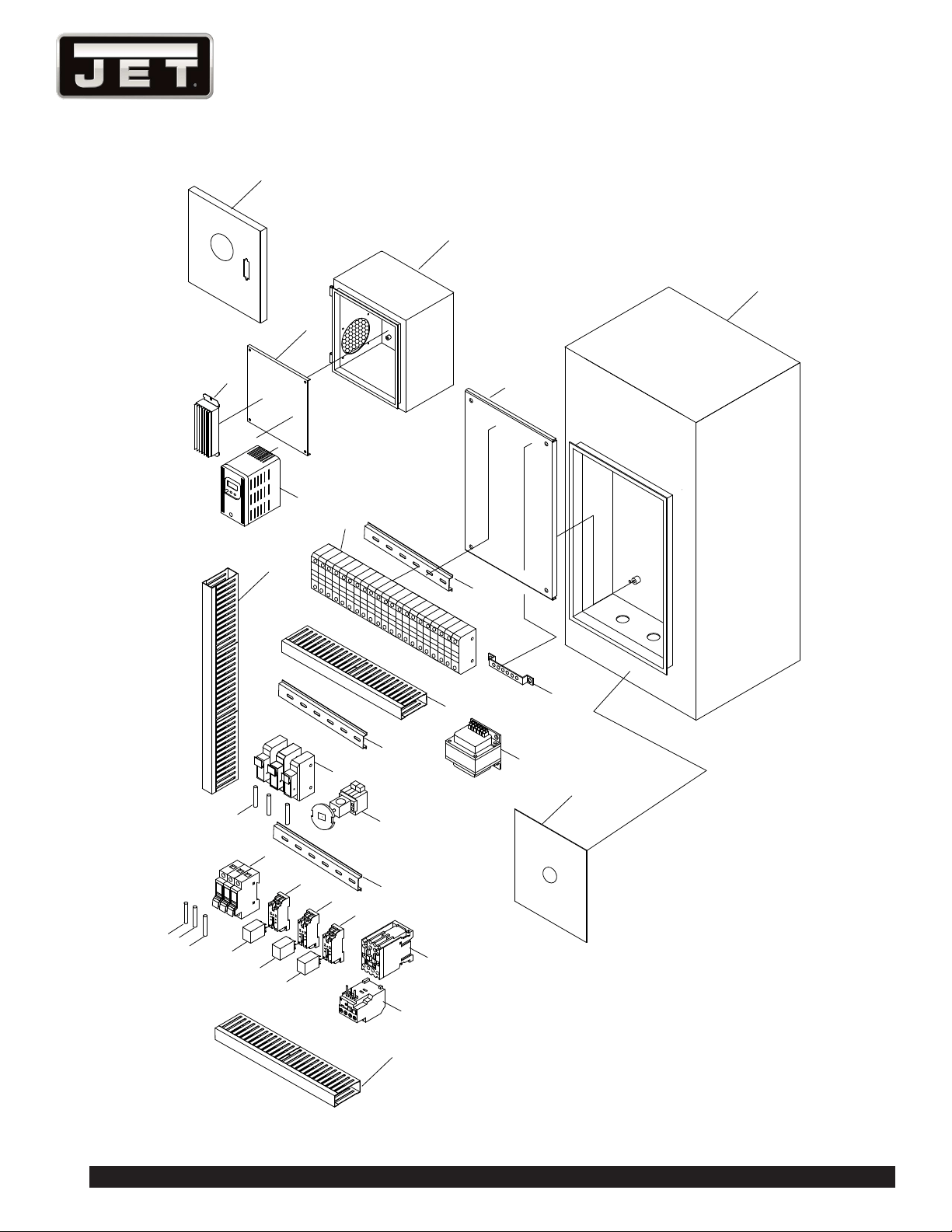
60
1236 Lathe
1
2
3
4
5
6
7
8
9
10
11
12
13
14
15
16
17
18
19
20
21
22
23
24
25
26
27
28
29
27
27
30
CONTROL PLATE ASSEMBLY

61
E-1236VS
CONTROL PLATE ASSEMBLY PARTS LIST
Index No. Parts No. Description Size Qty.
1 EBL1236VS-H01 Cover 300*300*20*1.2T 1
2 EBL1236VS-H02 Electric Box 300*300*178 1.2T 1
EBL1236VS-H01A Cover Assembly (Including #1~2) 1
3 EBL1236VS-H03 Plate 1
4 EBL1236VS-H04 Brake Resistance 260W 100Ω 1
5 EBL1236VS-H05 Inverter VFD-B Ac240v 2HP 1
6 EBL1236VS-H06 Floor Stand 437L*368W*15H 1
7 EBL1236VS-H07 Plate 1
8 EBL1236VS-H08 Track 1
9 EBL1236VS-H09 Terminal Blocks 1
10 EBL1236VS-H10 Earthing Terminal Blocks 1
11 EBL1236VS-H11 Trunking 1
12 EBL1236VS-H12 Trunking 1
13 EBL1236VS-H13 Track 1
14 EBL1236VS-H14 Control Circuit Transformer 120VC Ac24v(5A) 1
15 EBL1236VS-H15 Fuse Box 1
16 EBL1236VS-H16 Fuse Box 1
17 EBL1236VS-H17 Fuse Box 1
18 EBL1236VS-H18 Main Power Switch 690VAC 25A 1
19 EBL1236VS-H19 Fuse 5A 3
20 EBL1236VS-H20 Track 1
21 EBL1236VS-H21 Fuse Boxes 1
22 EBL1236VS-H22 Relay Socket 1
23 EBL1236VS-H23 Relay Socket 1
24 EBL1236VS-H24 Relay Socket 1
25 EBL1236VS-H25 Magnetic Contactor CU-11 Ac24v (3A1b) 1
26 EBL1236VS-H26 Fuse 30A 3
27 EBL1236VS-H27 Relay MY4N-J Ac24v 3
28 EBL1236VS-H28 Thermal Overload Relay RHU-10K1 0.45~0.63A 1
29 EBL1236VS-H29 Cover 1
30 EBL1236VS-H30 Trunking 1
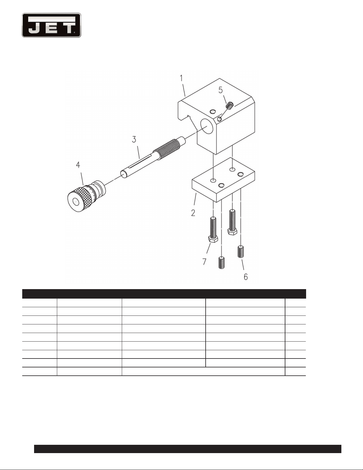
62
1236 Lathe
MICRO CARRIAGE STOP & PARTS LIST
Index No. Parts No. Description Size Qty.
1 E1236VS-IM1 Stop 60Lx60Wx46.5H 1
2 E1236VS-IM2 Clamping Plate 60Lx38Wx12H 1
3 E1236VS-IM3 Spindle Ø12.7x92L 1
4 E1236VS-IMI4 Scale Ring (Imperial Units) Ø25.4x37LxØ9.52 1
E1236VS-IMM4 Scale Ring (Metric Units) Ø25.4x37LxØ9.52 1
5 TS-1523011 Set Screw M6x6 1
6 TS-1523051 Set Screw M6x16 2
7 TS-1482051 Hex Cap Screw M6x25 2
E1236VS-IMA Micro Carriage Stop Assembly (#1~7) 1
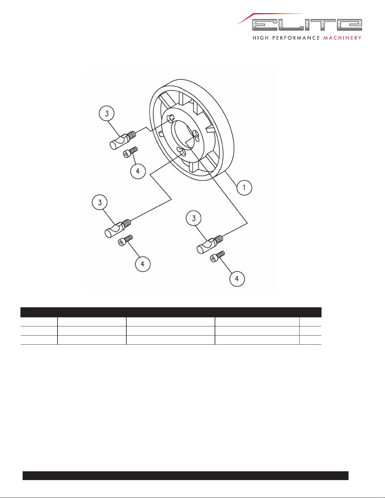
63
E-1236VS
FACE PLATE & PARTS LIST
Index No. Parts No. Description Size Qty.
1 EBL1236VS-FP01 Face Plate 10” Ø250x40H 1
3 EBL1236VS-G137 Stud D1-4 3
4 TS-1503051 Socket Head Cap Screw M6×20mm 3
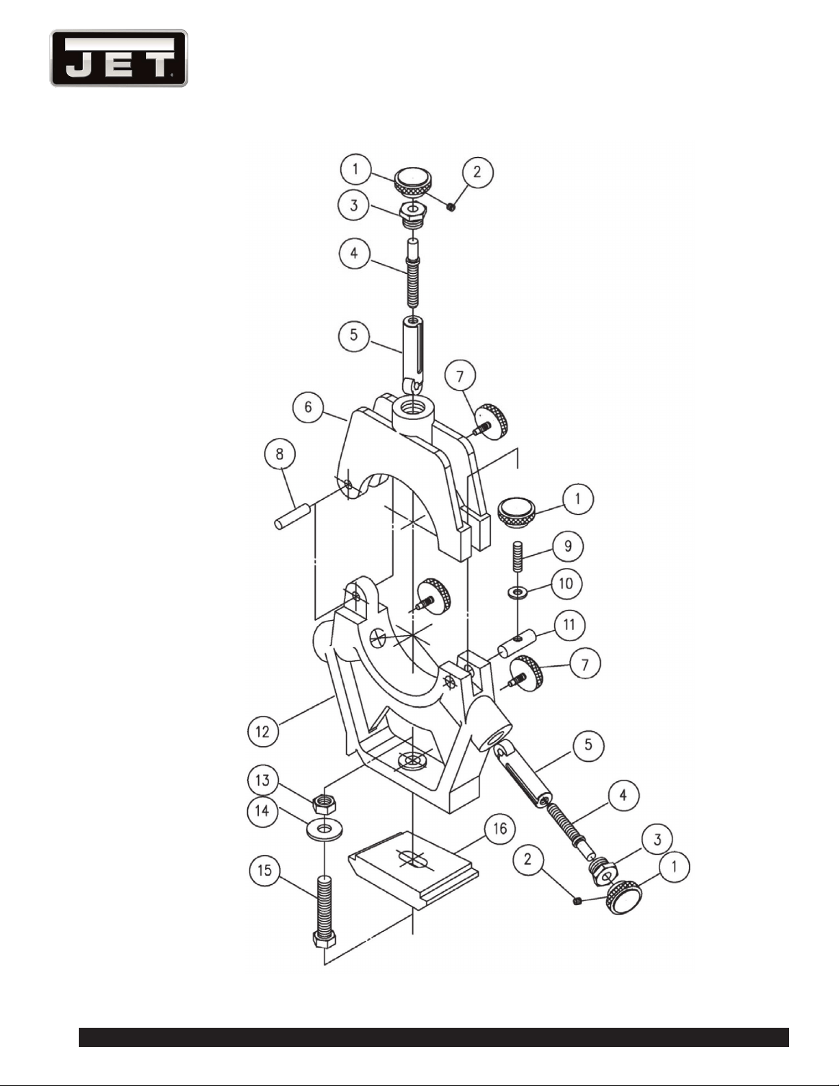
64
1236 Lathe
STEADY REST ASSEMBLY

65
E-1236VS
STEADY REST ASSEMBLY PARTS LIST
Index No. Parts No. Description Size Qty.
1 E-1440VS-FR01 Nut Ø20xØ24x25L 4
2 TS-1523011 Set Screw M6*6mm 3
3 E1440VS-FR03 Screw Ø23x17L 3
4 E1440VS-FR04 Set Screw Ø9.5x77L 3
E1440VS-FR01A Nut Assembly (includes #1~4) 3
5 E1440VS-FR05 Bearing Shaft Ø18.8(Ø24)x83L 3
6 E1236VS-SR06 Arm 168x32x125 mm 1
7 E1440VS-FR07 Set Screw Ø20xØ4.5x30L 3
8 E1440VS-SR08 Shaft Ø8x40L 1
9 E1440VS-SR09 Set Screw M8*55mm 1
10 TS-0732061 Washer 3/8 in 1
11 E1440VS-SR11 Pin Ø12.7x40L 1
12 E1236VS-SR12 Base 171x32x153 1
13 TS-0561051 Hex Nut 1/2-13 in 1
14 TS-0680061 Flat Washer 1/2 in. 1
15 TS-0070071 Hex Cap Screw 12-13 x 2-1/2 in. 1
16 EBL1236-F30 Clamp Plate 85L*94W*28h 1
EBL1236-SRA Steady Rest Assembly (#1~16)
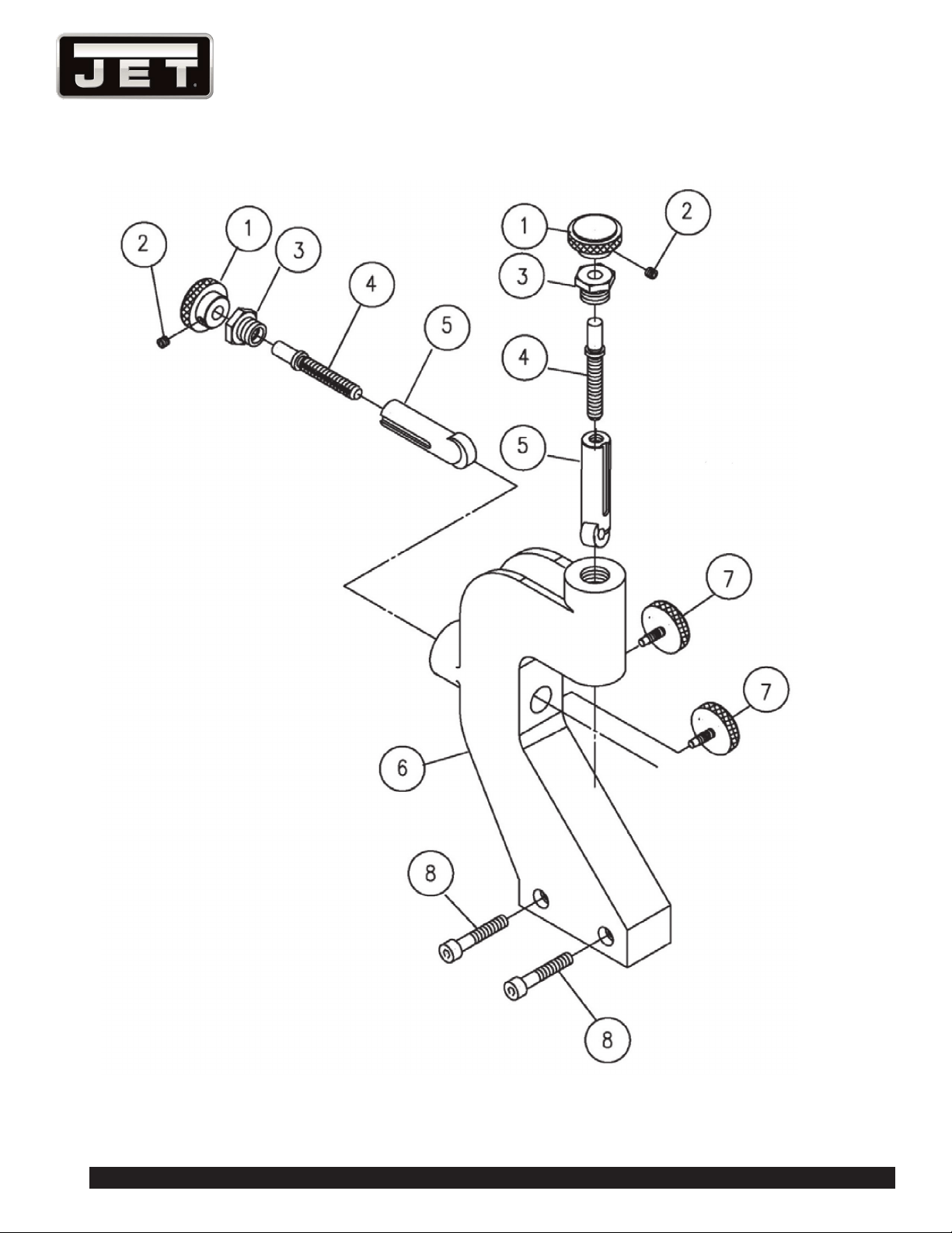
66
1236 Lathe
FOLLOW REST ASSEMBLY

67
E-1236VS
FOLLOW REST ASSEMBLY PARTS LIST
Index No. Parts No. Description Size Qty.
1 E1440VS-FR01 Nut Ø20xØ24x25L 2
2 TS-1523011 Set Screw M6*6mm 2
3 E1440VS-FR03 Screw Ø23x17L 2
4 E1440VS-FR04 Set Screw Ø9.5x77L 2
E1440VS-FR01A Nut Assembly (includes #1~4) 2
5 E1440VS-FR05 Bearing Shaft Ø18.8(Ø24)x83L 2
6 E1236VS-FR06 Follow Rest 271x32x159 mm 1
7 E1440VS-FR07 Set Screw Ø20(Ø4.5)x30L 2
8 TS-1490081 Socket Head Cap Screw M8*45mm 2
EBL1236-FRA Follow Rest Assembly (#1~8)
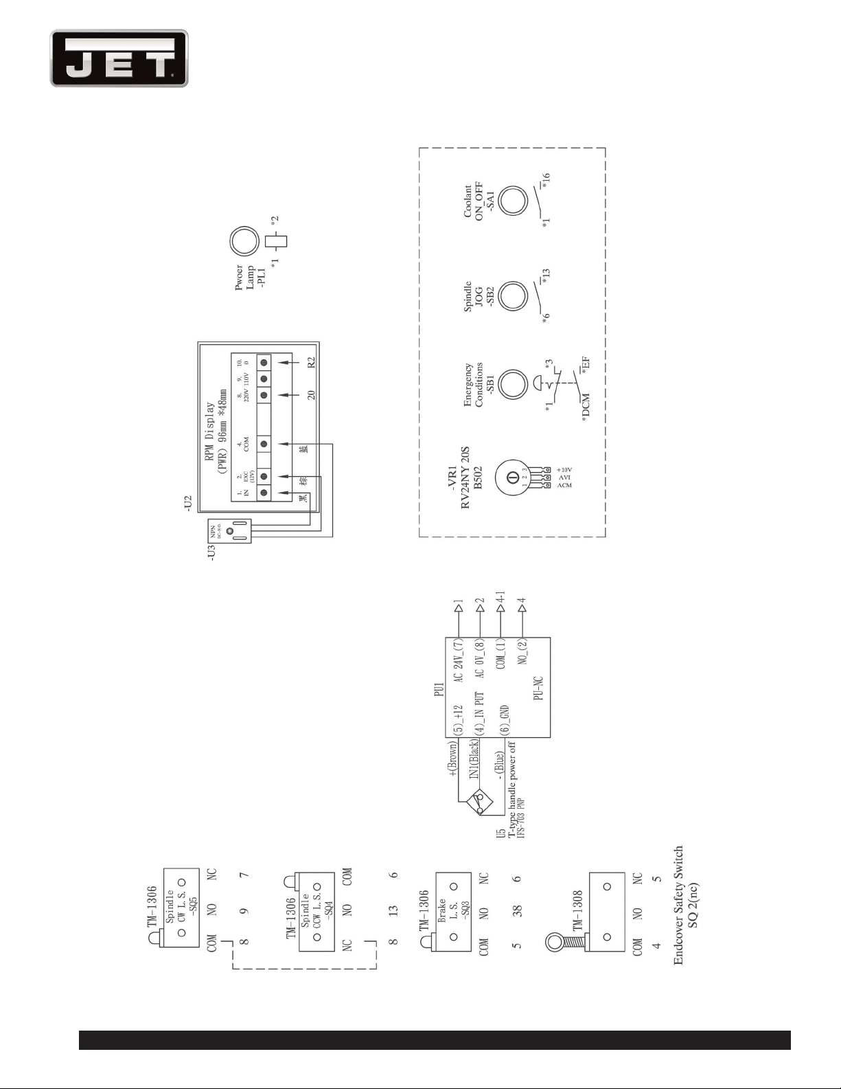
68
1236 Lathe
14.0 WIRING DIAGRAMS
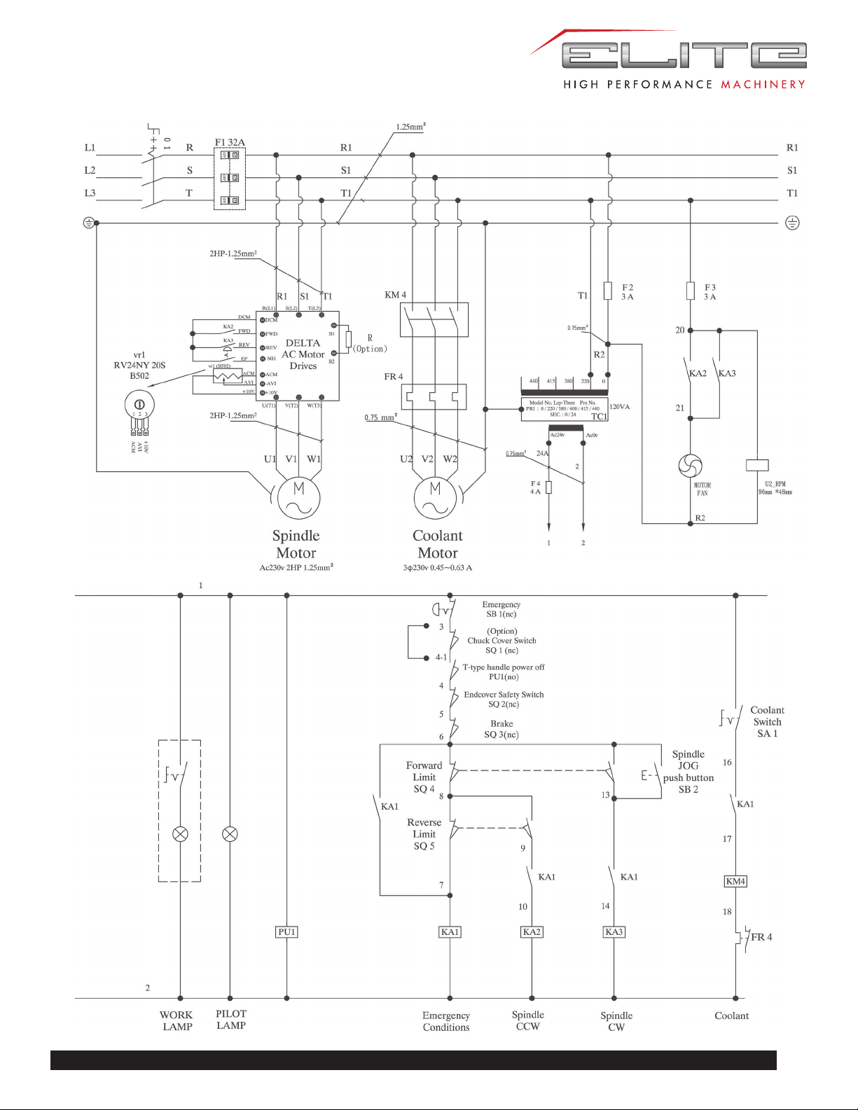
69
E-1236VS

70
1236 Lathe
15.0 SCHEDULE OF ELECTRICAL EQUIPMENT
Item
designation Circuit
Description and
function Technical data Quantity
U1 1 For main motor
spindle inverter
Ue=380V-
460V~
1.5kW 2HP
1
KM1 2,3 Relay contactor for
main motor reverse
Res 5A 240VAC
5A 30VDC
Coil 24VAC
50/60HZ
1
KM2 2,3 Relay contactor for
main motor forward
1
KM3 2,3 Magnetic contactor
for coolant pump
1
KM4 1 Magnetic contactor
for power supply
1
KA1 3 Magnetic contactor
for brake
1
FU1 1 Fuse boxes 10m/mX38m/m
100KA
500V aM25A
1
FU2
FU3
FU4 1 Fuse box 20mm
250V 1A
1
FU5 1 Fuse box 20mm
250V 1A
1
FU6 1 Fuse box 20mm
250V 4A
1
FR2 2,3 Thermal overload
relay for coolant
pump
1
QS1 1 Main power switch 1
HL1 3
Pilot light 1
TC1 1
Control circuit
Tranformer
Prim 220V/380V
Sec.
22V,24V,150VA
1
SA1 3
Selecting switch 1
SB1 3
Off hand switch
Emergency
1
SB2 3
Push button switch
(jogging switch)
1

71
E-1236VS
Item
designation Circuit
Description and
function Technical data Quantity
SB3 1
Push button switch
(power supply off)
1
SB4 1
Push button switch
(power supply on)
1
SQ1 3
Chuck guard switch 500V 6KV 10A 1
SQ2 3
Limit switch
Endcover safety
switch
500V 6KV 10A 1
SQ3 3
Limit switch for
brake
250V 15A 1
SQ4 3
Limit switch for main
motor forward
250V 15A 1
SQ5 3
Limit switch for main
motor reverse
250V 15A 1
M1 2
Squirrel-cage motors
Foot-mounted
60Hz, 220/360V
1400 rev/min
class E insulation
100L type ASEC,
1.5kW
1
M2 2
Coolant pump 50/60Hz,
220/400V
2850/3400 rev/
min type MT,
0.1kW
1

72
1236 Lathe
NOTES