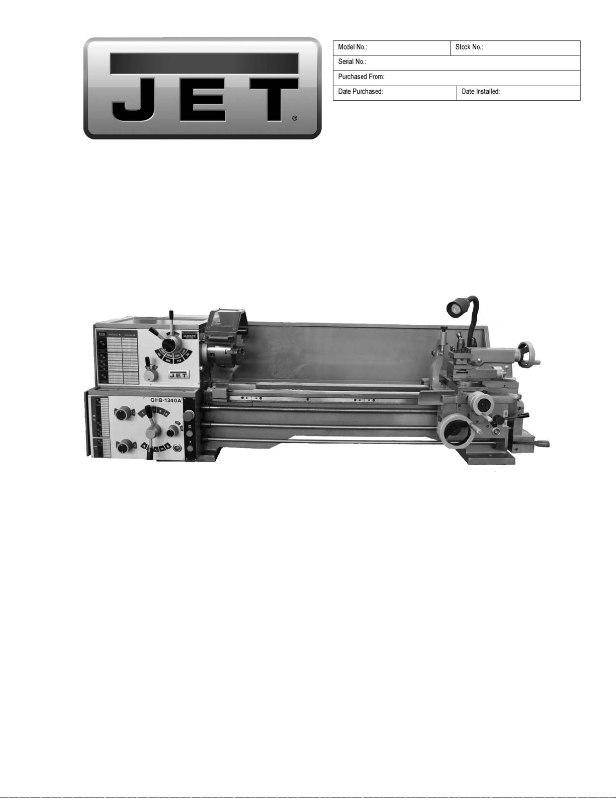
Operation and Maintenance Instructions
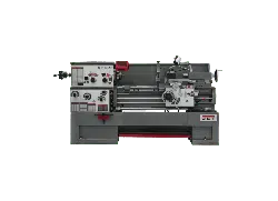
Geared Head Bench Lathe
Models GHB-1340A, GHB-1440A
(GHB-1340A shown with optional stand 321443AK)
For Parts List and Electrical Diagrams, see document M-321357A
JET
427 New Sanford Road
LaVergne, Tennessee 37086 Part No. M-321357A-1
Ph.: 800-274-6848 Revision H1 08/2018
www.jettools.com Copyright © 2014 JET
This .pdf document is bookmarked

2
1.0 IMPORTANT SAFETY
INSTRUCTIONS
Read and understand the entire owner's
manual before attempting set-up or operation
of this lathe.
1. This machine is designed and intended for use
by properly trained and experienced personnel
only. If you are not familiar with the proper and
safe use of lathes, do not use this machine
until proper training and knowledge have been
obtained.
2. Keep guards in place. Safety guards must be
kept in place and in working order.
3. Remove adjusting keys and wrenches. Before
turning on machine, check to see that any
adjusting wrenches are removed from the tool.
4. Reduce the risk of unintentional starting. Make
sure switch is in the OFF position before
plugging in the tool.
5. Do not force tools. Always use a tool at the
rate for which it was designed.
6. Use the right tool. Do not force a tool or
attachment to do a job for which it was not
designed.
7. Maintain tools with care. Keep tools sharp and
clean for best and safest performance. Follow
instructions for lubrication and changing
accessories.
8. Always disconnect the tool from the power
source before adjusting or servicing.
9. Check for damaged parts. Check for alignment
of moving parts, breakage of parts, mounting,
and any other condition that may affect the
tool’s operation. A guard or any part that is
damaged should be repaired or replaced.
10. Turn power off. Never leave a tool unattended.
Do not leave a tool until it comes to a complete
stop.
11. Keep work area clean. Cluttered areas and
benches invite accidents.
12. Do not use in a dangerous environment. Do
not use power tools in damp or wet locations,
or expose them to rain. Keep work area well
lighted.
13. Keep children and visitors away. All visitors
should be kept a safe distance from the work
area.
14. Make the workshop child proof. Use padlocks,
master switches, and remove starter keys.
15. Wear proper apparel. Loose clothing, gloves,
neckties, rings, bracelets, or other jewelry may
get caught in moving parts. Non-slip footwear
is recommended. Wear protective hair
covering to contain long hair. Do not wear any
type of glove.
16. Always use safety glasses. Every day glasses
only have impact resistant lenses; they are not
safety glasses.
17. Do not overreach. Keep proper footing and
balance at all times.
18. Do not place hands near the chuck while the
machine is operating.
19. Do not perform any set-up work while machine
is operating.
20. Read and understand all warnings posted on
the machine.
21. This manual is intended to familiarize you with
the technical aspects of this lathe. It is not, nor
was it intended to be, a training manual.
22. Failure to comply with all of these warnings
may result in serious injury.
WARNING: Some dust, fumes and gases
created by power sanding, sawing, grinding,
drilling, welding and other construction activities
contain chemicals known to the State of
California to cause cancer and birth defects or
other reproductive harm. Some examples of
these chemicals are:
• lead from lead based paint
• crystalline silica from bricks, cement and other
masonry products
• arsenic and chromium from chemically treated
lumber
Your risk of exposure varies, depending on how
often you do this type of work. To reduce your
exposure to these chemicals, work in a well-
ventilated area and work with approved safety
equipment, such as dust masks that are
specifically designed to filter out microscopic
particles. For more information go to
http://www.p65warnings.ca.gov/ and http://www.
p65warnings.ca.gov/wood.
WARNING: This product can expose you to
chemicals including lead and cadmium which
are known to the State of California to cause
cancer, and phthalates which are known to the
State of California to cause birth defects or other
reproductive harm. For more information go to
http://www.p65warnings. ca.gov.

3
Familiarize yourself with the following safety notices used in this manual:
This means that if precautions are not heeded, it may result in minor injury and/or possible
machine damage.
This means that if precautions are not heeded, it may result in serious, or possibly even fatal,
injury.
2.0 Table of contents
Section Page
1.0 IMPORTANT SAFETY INSTRUCTIONS ....................................................................................................... 2
2.0 Table of contents ............................................................................................................................................ 3
3.0 Warranty and service ..................................................................................................................................... 4
4.0 About this manual .......................................................................................................................................... 5
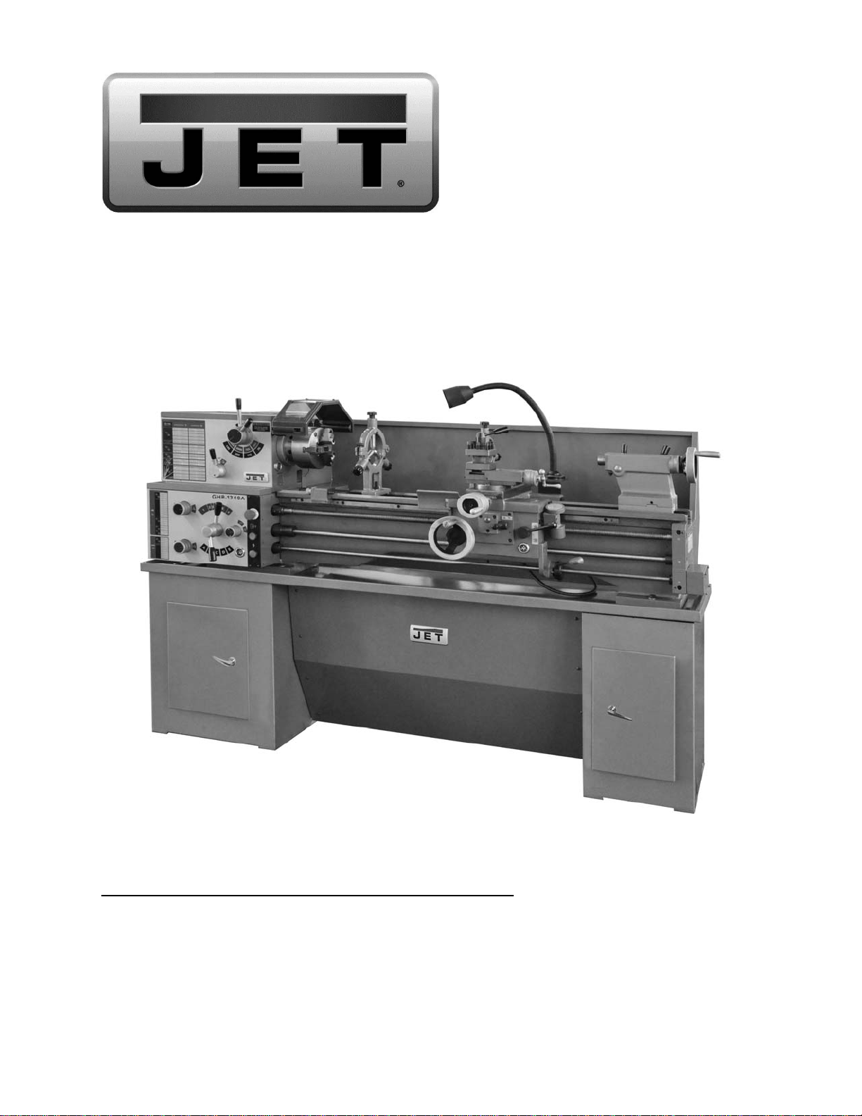
5.0 Dimensions for optional stand (p/n 321443AK) .............................................................................................. 5
6.0 Specifications ................................................................................................................................................. 6
7.0 Setup and assembly ....................................................................................................................................... 7
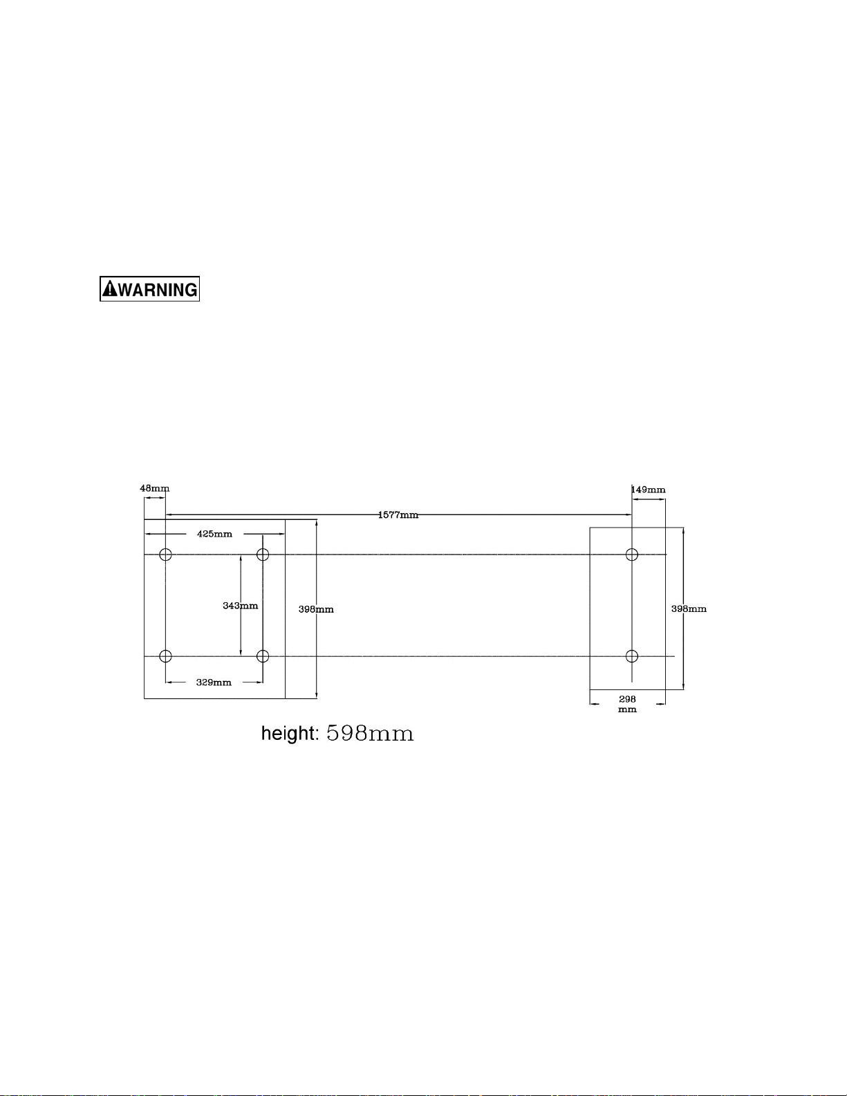
7.1 Shipping contents ....................................................................................................................................... 7
7.2 Uncrating and Cleanup ............................................................................................................................... 8
7.3 Chuck Preparation (Three Jaw) ................................................................................................................. 8
7.4 Chuck Guard Installation ............................................................................................................................ 9
8.0 Lubrication ...................................................................................................................................................... 9
9.0 Electrical Connections .................................................................................................................................. 10
10.0 General Description .................................................................................................................................... 10
10.1 Lathe Bed ............................................................................................................................................... 10
10.2 Carriage .................................................................................................................................................. 10
10.3 Headstock ............................................................................................................................................... 10
10.4 Four Way Tool Post ................................................................................................................................ 10
10.5 Apron ...................................................................................................................................................... 11
10.6 Tailstock ................................................................................................................................................. 11
10.7 Leadscrew and Feed Rod ...................................................................................................................... 11
10.8 Gear Box ................................................................................................................................................ 11
10.9 Steady Rest ............................................................................................................................................ 11
10.10 Follow Rest ........................................................................................................................................... 11
11.0 Controls ...................................................................................................................................................... 11
12.0 Operation ................................................................................................................................................... 13
12.1 Break-In Procedure ................................................................................................................................ 13
12.2 Feed and Thread Selection .................................................................................................................... 13
12.3 Change Gear Replacement .................................................................................................................... 13
12.4 Automatic Feed Operation and Feed Changes ...................................................................................... 13
12.5 Powered Carriage Travel ....................................................................................................................... 14
12.6 Thread Cutting ........................................................................................................................................ 14
13.0 Adjustments ............................................................................................................................................... 14
13.1 Saddle adjustment .................................................................................................................................. 14
13.2 Cross Slide adjustment .......................................................................................................................... 14
13.3 Compound Slide adjustment .................................................................................................................. 14
13.4 Tailstock adjustment ............................................................................................................................... 14
13.5 Half Nut Gib adjustment ......................................................................................................................... 15
13.6 Headstock Alignment ............................................................................................................................. 15
13.7 Removing Gap Bridge ............................................................................................................................ 15
13.8 Installing Gap Bridge .............................................................................................................................. 15
14.0 Thread and Feed Chart .............................................................................................................................. 16

4
3.0 Warranty and service
JET warrants every product it sells against manufacturers’ defects. If one of our tools needs service or repair, please
contactTechnical Service by calling 1-800-274-6846, 8AM to 5PM CST, Monday through Friday.
Warranty Period
The general warranty lasts for the time period specified in the literature included with your product or on the official
JET branded website.
• JET products carry a limited warranty which varies in duration based upon the product. (See chart below)
• Accessories carry a limited warranty of one year from the date of receipt.
• Consumable items are defined as expendable parts or accessories expected to become inoperable within a
reasonable amount of use and are covered by a 90 day limited warranty against manufacturer’s defects.
Who is Covered
This warranty covers only the initial purchaser of the product from the date of delivery.
What is Covered
This warranty covers any defects in workmanship or materials subject to the limitations stated below. This warranty
does not cover failures due directly or indirectly to misuse, abuse, negligence or accidents, normal wear-and-tear,
improper repair, alterations or lack of maintenance. JET woodworking machinery is designed to be used with Wood.
Use of these machines in the processing of metal, plastics, or other materials may void the warranty. The exceptions
are acrylics and other natural items that are made specifically for wood turning.
Warranty Limitations
Woodworking products with a Five Year Warranty that are used for commercial or industrial purposes default to a
Two Year Warranty. Please contact Technical Service at 1-800-274-6846 for further clarification.
How to Get Technical Support
Please contact Technical Service by calling 1-800-274-6846.Please note that you will be asked to provide proof
of initial purchase when calling. If a product requires further inspection, the Technical Service representative will
explain and assist with any additional action needed.JET has Authorized Service Centers located throughout the
United States. For the name of an Authorized Service Center in your area call 1-800-274-6846 or use the Service
Center Locator on the JET website.
More Information
JET is constantly adding new products. For complete, up-to-date product information, check with your local distributor
or visit the JET website.
How State Law Applies
This warranty gives you specific legal rights, subject to applicable state law.
Limitations on This Warranty
JET LIMITS ALL IMPLIED WARRANTIES TO THE PERIOD OF THE LIMITED WARRANTY FOR EACH PRODUCT.
EXCEPT AS STATED HEREIN, ANY IMPLIED WARRANTIES OF MERCHANTABILITY AND FITNESS FOR A
PARTICULAR PURPOSE ARE EXCLUDED. SOME STATES DO NOT ALLOW LIMITATIONS ON HOW LONG AN
IMPLIED WARRANTY LASTS, SO THE ABOVE LIMITATION MAY NOT APPLY TO YOU.
JET SHALL IN NO EVENT BE LIABLE FOR DEATH, INJURIES TO PERSONS OR PROPERTY, OR FOR
INCIDENTAL, CONTINGENT, SPECIAL, OR CONSEQUENTIAL DAMAGES ARISING FROM THE USE OF OUR
PRODUCTS. SOME STATES DO NOT ALLOW THE EXCLUSION OR LIMITATION OF INCIDENTAL OR
CONSEQUENTIAL DAMAGES, SO THE ABOVE LIMITATION OR EXCLUSION MAY NOT APPLY TO YOU.
JET sells through distributors only. The specifications listed in JET printed materials and on official JET website are
given as general information and are not binding. JET reserves the right to effect at any time, without prior notice,
those alterations to parts, fittings, and accessory equipment which they may deem necessary for any reason
whatsoever. JET
®
branded products are not sold in Canada by JPW Industries, Inc.
Product Listing with Warranty Period
90 Days – Parts; Consumable items
1 Year – Motors; Machine Accessories
2 Year – Metalworking Machinery; Electric Hoists, Electric Hoist Accessories; Woodworking Machinery used
for industrial or commercial purposes
5 Year – Woodworking Machinery
Limited Lifetime – JET Parallel clamps; VOLT Series Electric Hoists; Manual Hoists; Manual Hoist
Accessories; Shop Tools; Warehouse & Dock products; Hand Tools; Air Tools
NOTE: JET is a division of JPW Industries, Inc. References in this document to JET also apply to JPW Industries,
Inc., or any of its successors in interest to the JET brand.
5
4.0 About this manual
This manual is provided by JET, covering the safe operation and maintenance procedures for a JET Model
GHB-1340A and GHB-1440A Lathe. This manual contains instructions on installation, safety precautions,
general operating procedures, and maintenance instructions. Your machine has been designed and
constructed to provide consistent, long-term operation if used in accordance with the instructions as set forth in
this document.
If there are questions or comments, please contact your local supplier or JET. JET can also be reached at our
web site: www.jettools.com.
Retain this manual for future reference. If the machine transfers ownership, the manual should accompany it.
Read and understand the entire contents of this manual before attempting assembly
or operation! Failure to comply may cause serious injury!
5.0 Dimensions for optional stand (p/n 321443AK)
To purchase this optional stand for the GHB-1340A Lathe, contact your dealer or call JET customer service.
Figure 1

6
6.0 Specifications
Stock Number ............................................................................... 321357A ............................................ 321359A
Model Number .......................................................................... GHB-1340A ....................................... GHB-1440A
Capacities:
Swing Over Bed ..................................................................................... 13" ............................................... 14-1/5”
Swing Over Cross Slide ................................................................. 7-25/32" ........................................................ 9”
Swing Through Gap ......................................................................... 18-3/4" ...................................................... 20”
Length of Gap .......................................................................................... 8” ........................................................ 8”
Distance Between Centers ..................................................................... 40" ...................................................... 40”
Headstock:
Hole Through Spindle ........................................................................ 1-3/8" ................................................. 1-3/8”
Spindle Nose ........................................................................................ D1-4 ................................................... D1-4
Taper in Spindle Nose ......................................................................... MT-5 .................................................. MT-5
Spindle Taper Adapter ........................................................................ MT-3 .................................................. MT-3
Spindle Bearing Type ................................................. Taper Roller Bearing .......................... Taper Roller Bearing
Number of Spindle Speeds ....................................................................... 8 ......................................................... 8
Range of Spindle Speeds ..................................................... 70-2000 RPM ..................................... 70-2000 RPM
Gearbox:
Number of Longitudinal and Cross Feed Rates ................................. 22/22 .................................................. 22/22
Range of Longitudinal Feeds (inch/rev) .......................... 0.0018" – 0.0374" .............................. 0.0018" – 0.0374"
Range of Cross Feeds (inch/rev) .................................... 0.0006" – 0.0130" .............................. 0.0006" – 0.0130"
Number of Inch Threads ......................................................................... 38 ....................................................... 38
Range of Inch Threads .......................................................... 3-1/2 – 80 TPI .................................... 3-1/2 – 80 TPI
Number of Metric Threads ...................................................................... 23 ....................................................... 23
Range of Metric Threads ......................................................... 0.45 - 10mm ....................................... 0.45 - 10mm
Leadscrew ................................................................................ 7/8" × 8 TPI ........................................ 7/8" × 8 TPI
Feed Rod Diameter ............................................................................... 3/4” ..................................................... 3/4”
Compound and Carriage:
Toolpost Type ................................................................................... 4-Way ................................................ 4-Way
Maximum Tool Size ..................................................................... 5/8" x 5/8" .......................................... 5/8" x 5/8"
Maximum Compound Slide Travel ................................................. 2-11/16" ............................................. 2-11/16"
Maximum Cross Slide Travel ........................................................... 6-5/16" ............................................... 6-5/16"
Maximum Carriage Travel ...................................................................... 35" ......................................................35"
Tailstock:
Tailstock Spindle Travel ..................................................................... 3-3/4" ................................................. 3-3/4"
Diameter of Tailstock Spindle ............................................................ 1-1/4" ................................................. 1-1/4"
Taper in Tailstock Spindle ................................................................... MT-3 .................................................. MT-3
Miscellaneous:
Steady Rest Capacity ............................................................... 1/4" – 2-5/8" ....................................... 1/4" – 2-5/8"
Follow Rest Capacity ............................................................... 1/4" – 2-3/4" ....................................... 1/4" – 2-3/4"
Length of Bed ......................................................................................... 54" ......................................................54"
Width of Bed ....................................................................................... 7-3/8" ................................................. 7-3/8"
Height of Bed ......................................................................................... 12" ......................................................12"
Overall Dimensions ................................................ 79"L x 28-1/2"W x 30"H ..................... 79"L x 28-1/2"W x 30"H
Main Motor ................................................................ 2HP, 1PH, 230V only ......................... 2HP, 1PH, 230V only
Net Weight (approx.) ..................................................................... 1155 lbs. ............................................ 1210 lbs.
Shipping Weight (approx.) ............................................................. 1365 lbs. ............................................ 1430 lbs.
The specifications in this manual were current at time of publication, but because of our policy of continuous
improvement, JET reserves the right to change specifications at any time and without prior notice, without incurring
obligations.
7
7.0 Setup and assembly
7.1 Shipping contents
See Figure 2.
1 Lathe
1 Steady Rest (mounted on lathe)
1 Follow Rest (mounted on lathe)
1 6" Three Jaw Chuck (mounted on lathe)
1 8" Four Jaw Chuck
1 12" Face Plate (strapped to container)
3 Cam Locks
3 Socket Head Cap Screws
1 Tool Box (strapped to container)
1 Chip Tray
1 Splash Guard
1 Lifting Hook
2 Lifting Blocks
Tool Box:
3 Open End Wrenches (9/11, 10/12,12/14mm)
1 Touch-Up Paint
1 Oil Can
1 Hex Key Set (2, 2.5, 3, 4, 5, 6, 8mm)
2 Shear Pins
1 33T Gear
1 44T Gear
1 46T Gear
1 48T Gear
1 52T Gear
2 T-Handle Chuck Wrenches
1 Tool Post Wrench
2 MT-3 Centers
1 MT-3 to MT-5 Center Sleeve
1 Cross Point Screwdriver
1 Flat Head Screwdriver
1 Key for Cam Locks
1 Operating Instructions
1 Part’s List
1 Warranty Card
Figure 2
8
7.2 Uncrating and Cleanup
Machine is heavy. Use an
appropriate lifting device and use extreme
caution when moving the machine to its final
location. Failure to comply may cause serious
injury.
1. Finish removing the wooden crate from around
the lathe.
2. Unbolt the lathe from the shipping crate
bottom.
3. Choose a location for the lathe that is dry, has
good lighting, and has enough room to be able
to service the lathe on all four sides.
4. Move the carriage and tailstock to the tailstock
end of the bed.
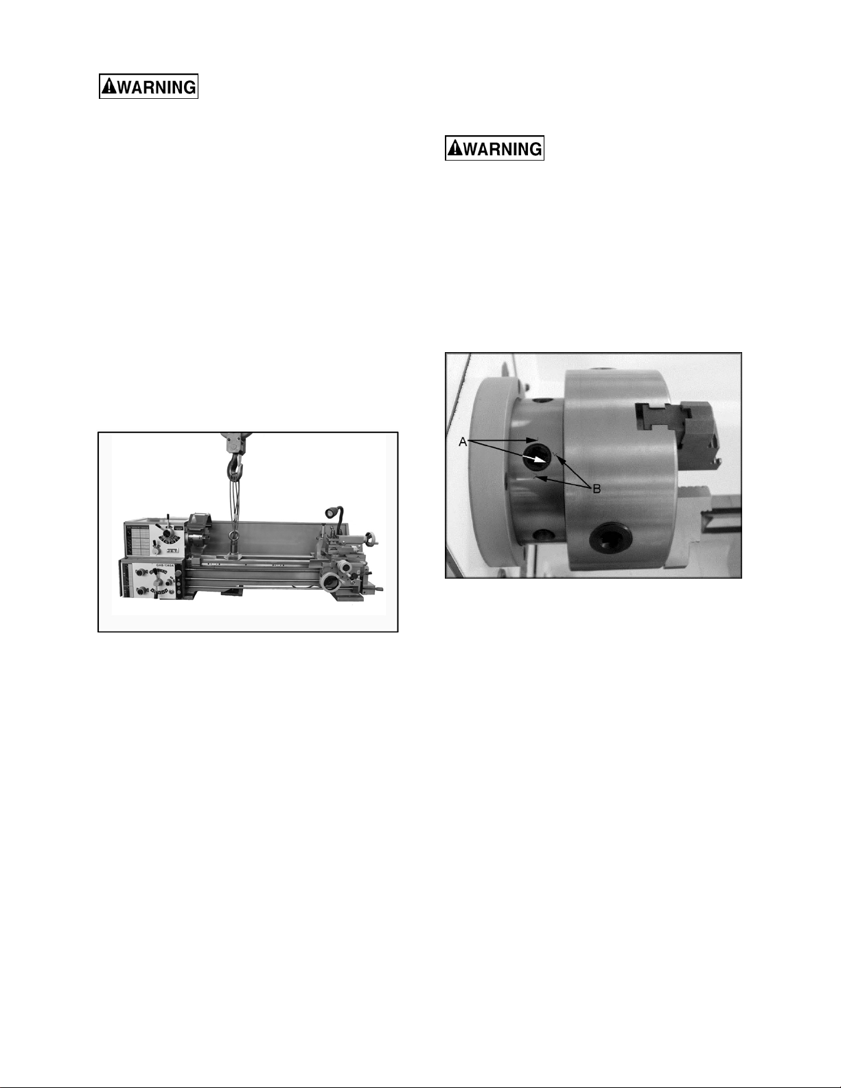
5. Assemble parts fastened to the crate bottom
used to lift the lathe. See Fig. 3. (Note: Lifting
parts are not tightened in Fig. 3 to show
detail.) Using a piece of leather or a block of
wood under the metal block to protect the
ways during lifting is highly recommended.
Figure 3
6. With adequate lifting equipment, slowly raise
the lathe off the shipping crate bottom. Make
sure lathe is balanced before moving to sturdy
bench or optional stand.
7. To avoid twisting the bed, the lathe's location
must be absolutely flat and level. Bolt the lathe
to the stand (if used). If using a bench,
through- bolt for best performance.
8. Clean all rust protected surfaces using a mild
commercial solvent, kerosene or diesel fuel.
Do not use paint thinner, gasoline, or lacquer
thinner. These will damage painted surfaces.
Cover all cleaned surfaces with a light film of
Mobil DTE® Oil Heavy Medium.
9. Remove the end gear cover. Clean all
components of the end gear assembly and
coat all gears with a heavy, non-slinging
grease.
10. Using a machinist’s precision level on the
bedways, check to make sure lathe is level
side to side and front to back. Loosen
mounting bolts, shim, and tighten mounting
bolts, if necessary. The lathe must be level to
be accurate.
7.3 Chuck Preparation (Three Jaw)
Read and understand all
directions for chuck preparation. Failure to
comply may cause serious injury and/or
damage to the lathe.
Note: Before removing the chuck from the spindle,
place a way board across the bedways under the
chuck.
1. Support the chuck while turning three
camlocks 1/4 turn counter-clockwise with the
chuck key enclosed in the toolbox. Figure 4
shows the cam in the secure position. Line up
the two marks (A, Fig. 4) for removal.
Figure 4
2. Carefully remove the chuck from the spindle
and place on an adequate work surface.
3. Inspect the camlock studs. Make sure they
have not become cracked or broken during
transit. Clean all parts thoroughly with solvent.
Also clean the spindle and camlocks.
4. Cover all chuck jaws and scroll inside the
chuck with Mobilith® AW2. Cover the spindle,
cam locks, and chuck body with a light film of
Mobil DTE® Oil Heavy Medium.
5. Lift the chuck up to the spindle nose and press
onto the spindle. Tighten in place by turning
the cam locks 1/4 turn clockwise. The index
mark (A, Fig. 4) on the camlock should be
between the two indicator arrows (B, Fig. 4). If
the index mark is not between the two arrows,
remove the chuck and adjust the camlock
studs by either turning out one full turn (if cams
will not engage) or turning in one full turn (if
cams turn beyond indicator marks).
6. Install chuck and tighten in place.
ATTENTION: Only when the incised line on the
chuck lines up with that on the spindle, can the
chuck be mounted.
9
7.4 Chuck Guard Installation
Install the chuck guard to the headstock, if it is not
already mounted. (See parts breakdown if
clarification is needed for assembly.)
8.0 Lubrication
Lathe must be serviced at all
lubrication points and all reservoirs filled to
operating level before the lathe is placed into
service. Failure to comply may cause serious
damage to the lathe.
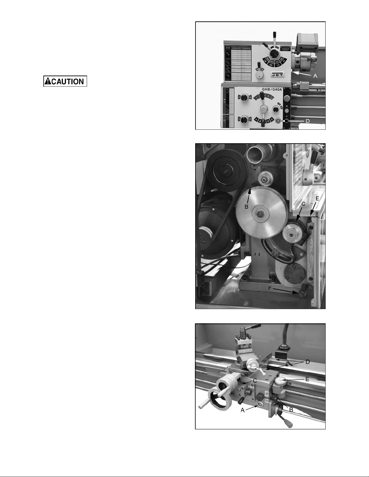
1. Headstock - Oil must be up to indicator mark
in oil sight glass (A, Fig. 5). Top off with Mobil
DTE® Oil Heavy Medium. Fill by pulling plug
located on top of the headstock cover,
underneath the rubber mat. Drain oil by
removing drain plug (B, Fig. 6) and refill after
the first month of operation. Clean out any
metal shavings. Then, change oil in the
headstock annually.
2. External Gears - Coat all gears with a heavy,
non-slinging grease, see Figure 6.
3. Gear Shaft - Remove the set screw (C, Fig. 6)
and oil with a couple drops of Mobil DTE® Oil
Heavy Medium once weekly.
4. Gearbox - Oil must be up to indicator mark in
oil sight glass (D, Fig. 7). Top off with Mobil
DTE® Oil Heavy Medium. Fill by removing
plug (E, Fig. 6). Drain oil by removing drain
plug (F, Fig. 6) and refill after the first month of
operation. Then, change oil in the gearbox
annually.
5. Apron - Oil must be up to indicator mark in oil
sight glass (A, Fig. 7). Top off with Mobil
DTE® Oil Heavy Medium. Fill by removing oil
plug (B, Fig. 7). After the first three months of
operation, drain oil completely (drain is on the
bottom of the apron) and refill with Mobil
DTE® Oil Heavy Medium, or equivalent to the
indicator line. Then, change oil annually.
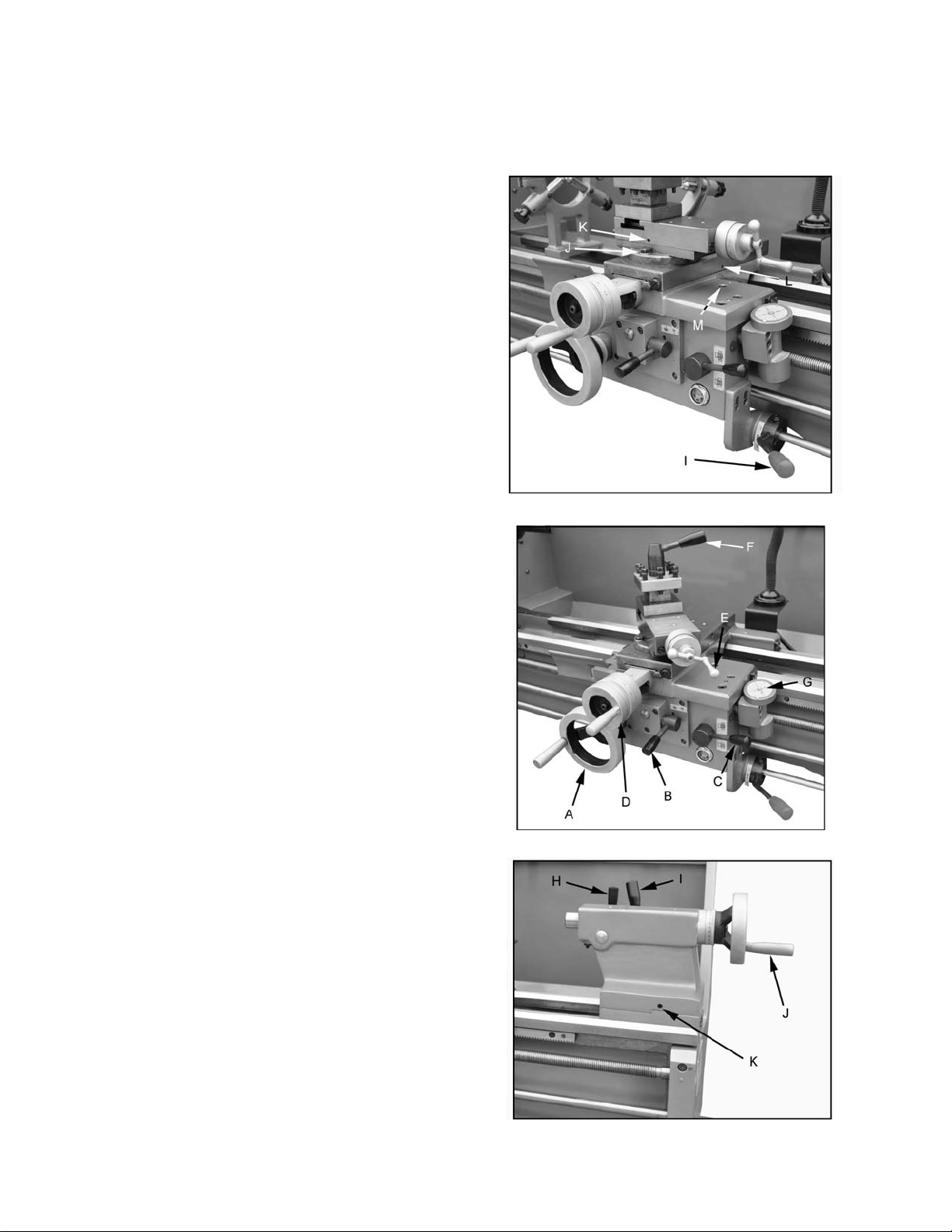
6. Feed Selector - Lubricate ball oiler (C, Fig. 7)
once daily with Mobil DTE® Oil Heavy
Medium.
7. Carriage - Lubricate two ball oilers (D, Fig. 7)
once daily with Mobil DTE® Oil Heavy
Medium.
8. Threading Dial Indicator - Lubricate ball oiler
(E, Fig. 7) once daily with Mobil DTE® Oil
Heavy Medium.
Figure 5
Figure 6
Figure 7
10
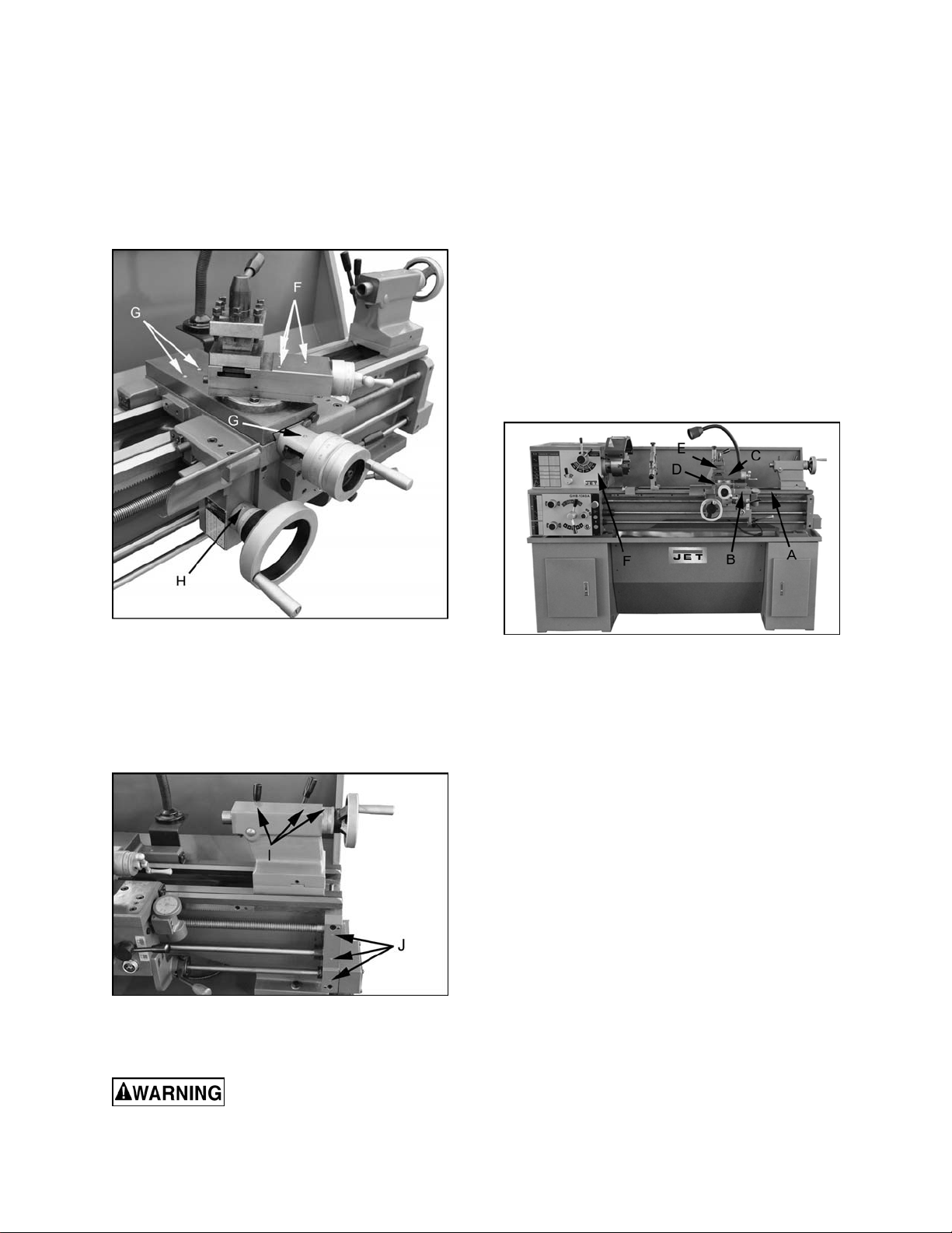
9. Compound Rest - Lubricate three ball oilers
(F, Fig. 8) once daily with Mobil DTE® Oil
Heavy Medium.
10. Cross Slide - lubricate four ball oilers (G, Fig.
8) once daily with Mobil DTE® Oil Heavy
Medium.
11. Longitudinal Feed Handwheel - Lubricate
ball oiler (H, Fig. 8) once daily with Mobil
DTE® Oil Heavy Medium.
Figure 8
12. Tailstock - Lubricate three ball oilers (I, Fig. 9)
once daily with Mobil DTE® Oil Heavy
Medium.
13. Leadscrew/Feed Rod - Lubricate three ball
oilers once daily (J, Fig. 9) with Mobil DTE®
Oil Heavy Medium.
Figure 9
9.0 Electrical Connections
All electrical connections must
be completed by a qualified electrician. Failure
to comply may cause serious injury and/or
damage to the machinery and property.
The GHB-1340A and GHB-1440A bench lathes are
rated at 2HP, 1PH, 230V only. Confirm power
available at the lathe's location is the same rating
as the lathe.
Make sure the lathe is properly grounded.
10.0 General Description
10.1 Lathe Bed
The lathe bed (A, Fig. 10) is made of high grade
cast iron. By combining high cheeks with strong
cross ribs, a bed with low vibration and high rigidity
is realized. Two precision ground V-slideways,
reinforced by heat hardening and grinding, are an
accurate guide for the carriage and headstock. The
main drive motor is mounted to the rear of the bed.
Figure 10
10.2 Carriage
The carriage (B, Fig. 10) is made from high quality
cast iron. The sliding parts are smooth ground.
The cross-slide is mounted on the carriage and
moves on a dove-tailed slide which can be
adjusted for play by means of the gibs.
The compound slide (C, Fig. 10), which is mounted
on the cross slide (D, Fig. 10), can be rotated
through 360°. The compound slide and the cross
slide travel in a dovetail slide and have adjustable
gibs. A four-way tool post (E, Fig. 10) is fitted on
the compound slide.
10.3 Headstock
The headstock (F, Fig. 10) is cast from high grade,
low vibration cast iron. It is mounted to the bed by
four bolts with two adjusting bolts for alignment. In
the head, the spindle is mounted on two precision
taper roller bearings. The hollow spindle has Morse
Taper #5 with a 1-1/2" bore.
10.4 Four Way Tool Post
The four-way tool post (E, Fig. 10) is mounted on
the compoundslide and allows a maximum of four
tools to be mounted simultaneously. Remember to
11
use a minimum of two clamping screws when
installing a cutting tool.
Figure 11
10.5 Apron
The apron (A, Fig. 11) is mounted to the carriage.
In the apron a half nut is fitted. The half nut gibs
can be adjusted from the outside. The half nut is
engaged by use of a lever. Quick travel of the
apron is accomplished by means of a bed-mounted
rack and pinion, operated by a hand wheel on the
front of the apron.
10.6 Tailstock
The tailstock (B, Fig. 11) slides on a v-way and can
be locked at any location by a clamping lever. The
tailstock has a heavy-duty spindle with a Morse
Taper #3.
10.7 Leadscrew and Feed Rod
The leadscrew (C Fig. 11) and feed rod (D, Fig. 11)
are mounted on the front of the machine bed. They
are connected to the gearbox at the left for
automatic feed and lead. They are supported by
bushings on both ends. Both are equipped with
brass shear pins.
10.8 Gear Box
The gear box (E, Fig. 11) is made from high quality
cast iron and is mounted to the left side of the
machine bed.
10.9 Steady Rest
The steady rest (F, Fig. 11) serves as a support for
shafts on the free tailstock end. The steady rest is
mounted on the bedway and secured from below
with a bolt, nut and locking plate. The sliding
fingers require continuous lubrication at the contact
points with the workpiece to prevent premature
wear.
10.10 Follow Rest
The traveling follow rest (G, Fig. 11) is mounted on
the saddle and follows the movement of the turning
tool. Only two fingers are required as the turning
tool takes the place of the third. The follow rest is
used for tuning operations on long, slender
workpieces. It prevents flexing of the workpiece
from the pressure of the cutting tool.
The sliding fingers are set similar to the steady
rest, free of play, but not binding. The sliding
fingers require continuous lubrication at the contact
points with the workpiece to prevent premature
wear.
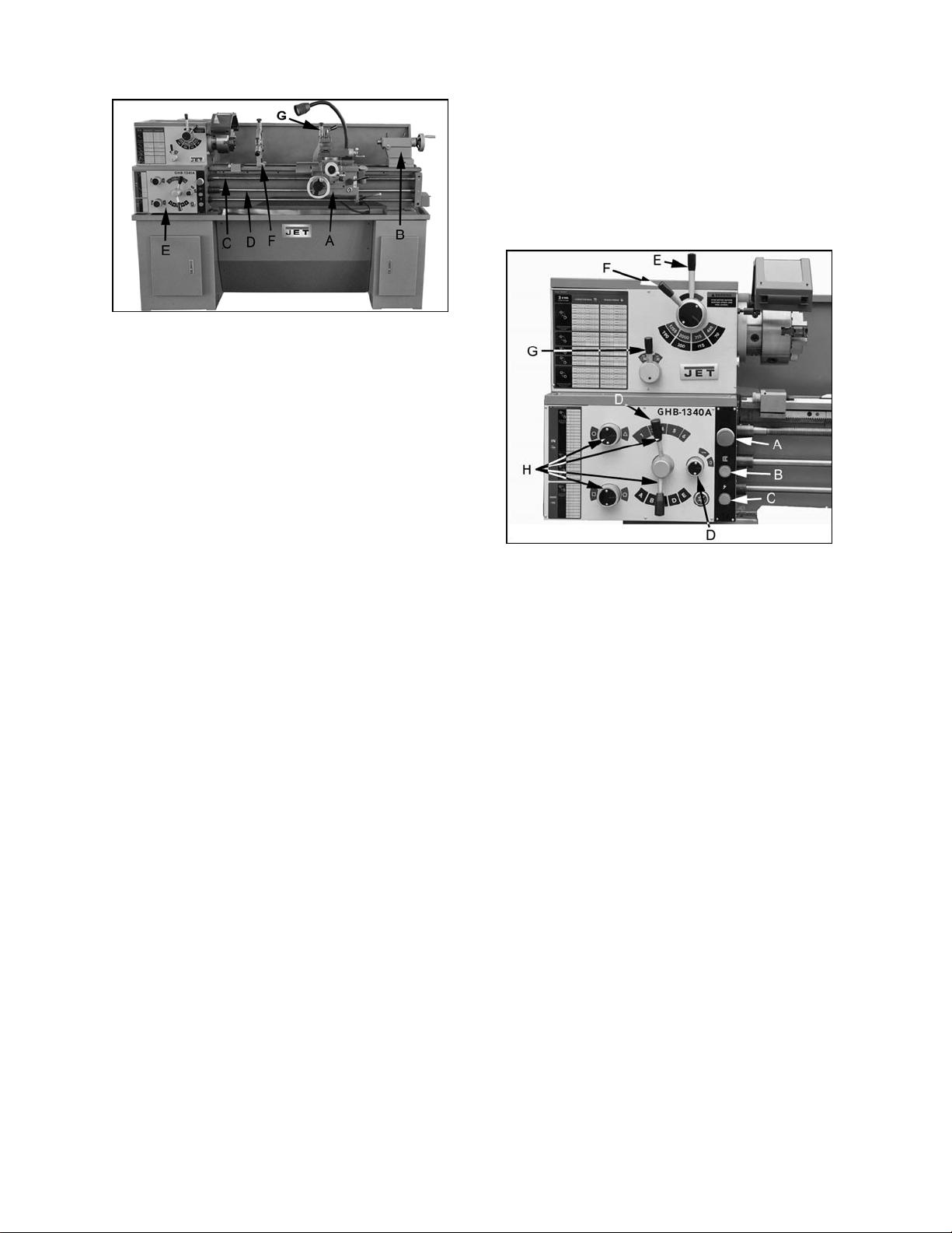
11.0 Controls
Figure 12
1. Emergency Stop Switch (A, Fig. 12) -
depress to stop all machine functions. Caution:
lathe will still have power. Turn clockwise to
re-set.
2. Jog Switch (B, Fig. 12) - Depress and release
to advance spindle momentarily.
3. Power Indicator Light (C, Fig. 12) - Lit
whenever lathe has power.
4. Feed Rod/Leadscrew Selector (D, Fig. 12)
Use knob and lever to activate leadscrew and
feed rod.
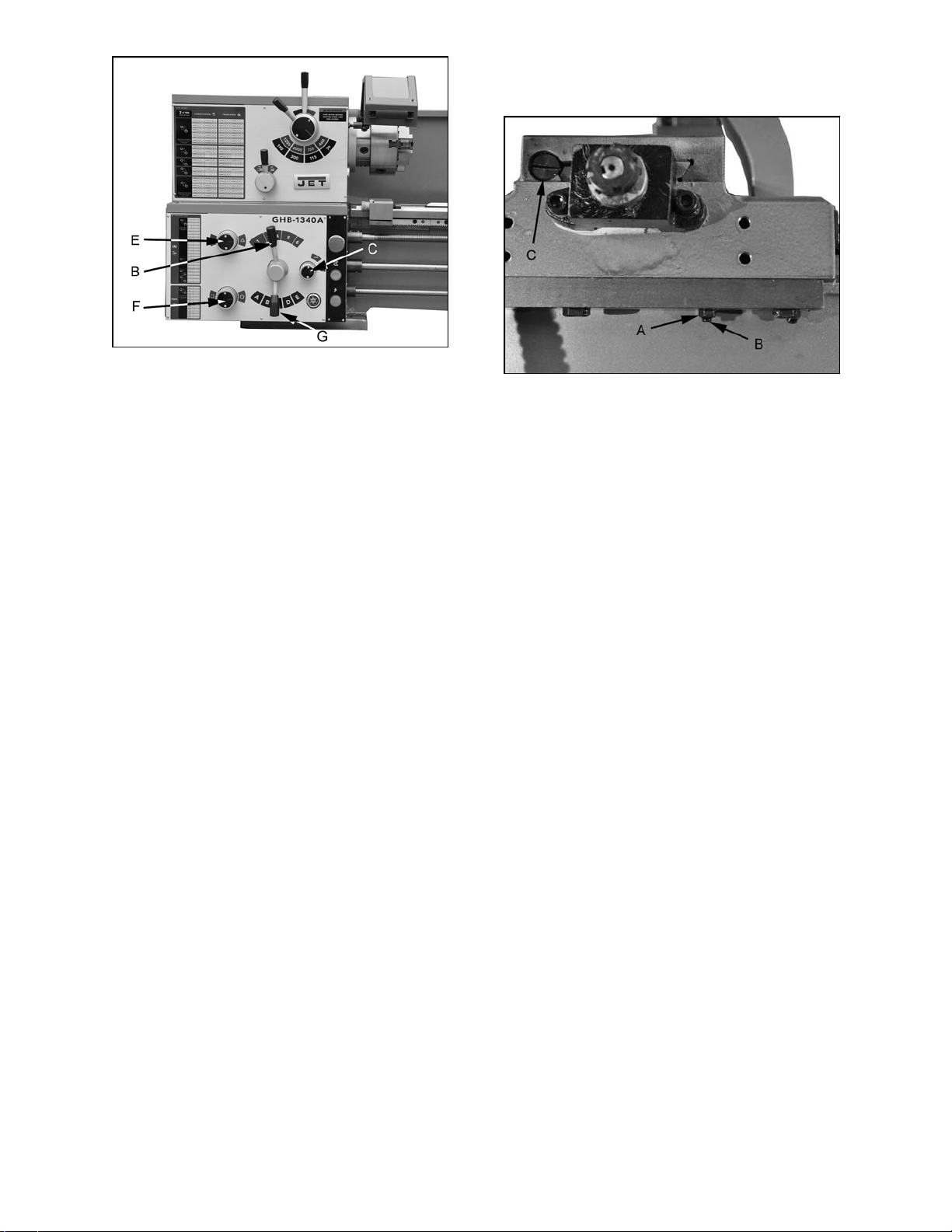
5. High/Low Speed Selector Lever (E, Fig. 12) -
Move to the left for low speed range. Move to
the right for high speed range.
6. Four Step Speed Selector Lever (F, Fig. 12)
- Use to select one of four spindle speeds in
either high or low range.
7. Feed Direction Selector (G, Fig. 12) - Selects
carriage travel direction when the chuck is
rotating in the forward direction or counter-
clockwise as viewed from the front of the
chuck.
8. Feed Rate Selector (H, Fig. 12) - Use knobs
and handles to set desired feed, or lead rates.
9. Forward/Reverse Lever (I, Fig. 13) - Pull
lever up for clockwise spindle rotation
(reverse). Push lever down for counter-
clockwise spindle rotation (forward). Neutral
12
position is a center detent and the spindle
remains idle.
10. Compound Rest Lock (J, Fig. 13) - Turn hex
nut clockwise to lock and counter-clockwise to
unlock.
11. Compound Slide Lock (K, Fig. 13) - Turn set
screw clockwise to tighten and counter-
clockwise to loosen.
12. Cross Slide Lock (L, Fig. 13) - Turn set screw
clockwise, and tighten to lock. Turn counter-
clockwise and loosen to unlock. Caution:
Cross slide lock screw must be unlocked
before engaging automatic feeds or damage to
the lathe may occur.
13. Carriage Lock (M, Fig. 13) - Turn hex socket
cap screw clockwise and tighten to lock. Turn
counterclockwise and loosen to unlock.
Caution:Carriage lock screw must be
unlocked before engaging automatic feeds or
damage to lathe may occur.
14. Longitudinal Traverse Hand Wheel (A, Fig.
14) – Rotate hand wheel clockwise to move
the apron assembly toward the tailstock (right).
Rotate the wheel counterclockwise to move
the apron assembly toward the headstock
(left).
15. Feed Selector (B, Fig. 14) – Push lever to the
left and down to activate the crossfeed
function. Pull lever to the right and up to
activate the longitudinal function.
16. Half Nut Engagement Lever (thread cutting)
(C, Fig. 14) – Move the lever down to engage.
Move the lever up to disengage.
17. Cross Traverse Handwheel (D, Fig. 14) –
Clockwise rotation moves the cross slide
toward the rear of the machine.
18. Compound Rest Traverse Handwheel (E,
Fig. 14) – Rotate clockwise or
counterclockwise to move or position.
19. Tool Post Clamping Lever (F, Fig. 14) –
Rotate counter-clockwise to loosen and
clockwise to tighten. Rotate the tool post when
the lever is unlocked.
20. Threading Dial (G, Fig. 14) – Engage by
pushing into the leadscrew. Pull out to
disengage. The dial indicator and chart will
specify at which point a thread can be entered.
21. Tailstock Quill Clamping Lever (H, Fig. 15) –
Lift up to lock the spindle. Push down to
unlock.
22. Tailstock Clamping Lever (I, Fig. 15) – Lift up
lever to lock. Push down lever to unlock.
23. Tailstock Quill Traverse Handwheel (J, Fig.
15) – Rotate clockwise to advance the quill.
Rotate counter-clockwise to retract the quill.
24. Tailstock Off-Set Adjustment (K, Fig. 15) –
Three set screws located on the tailstock base
are used to off-set the tailstock for cutting
tapers. Loosen lock screw on tailstock end.
Loosen one side set screw (K, Fig. 15) while
tightening the other until the amount of off-set
is indicated on scale. Tighten lock screw.
Figure 13
Figure 14
Figure 15
13
12.0 Operation
12.1 Break-In Procedure
During manufacturing and testing, this lathe has
been operated in the low R.P.M. range for three
hours.
To allow time for the gears and bearings to break-
in and run smoothly, do not run the lathe above
755 R.P.M. for the first six hours of operation and
use.
12.2 Feed and Thread Selection
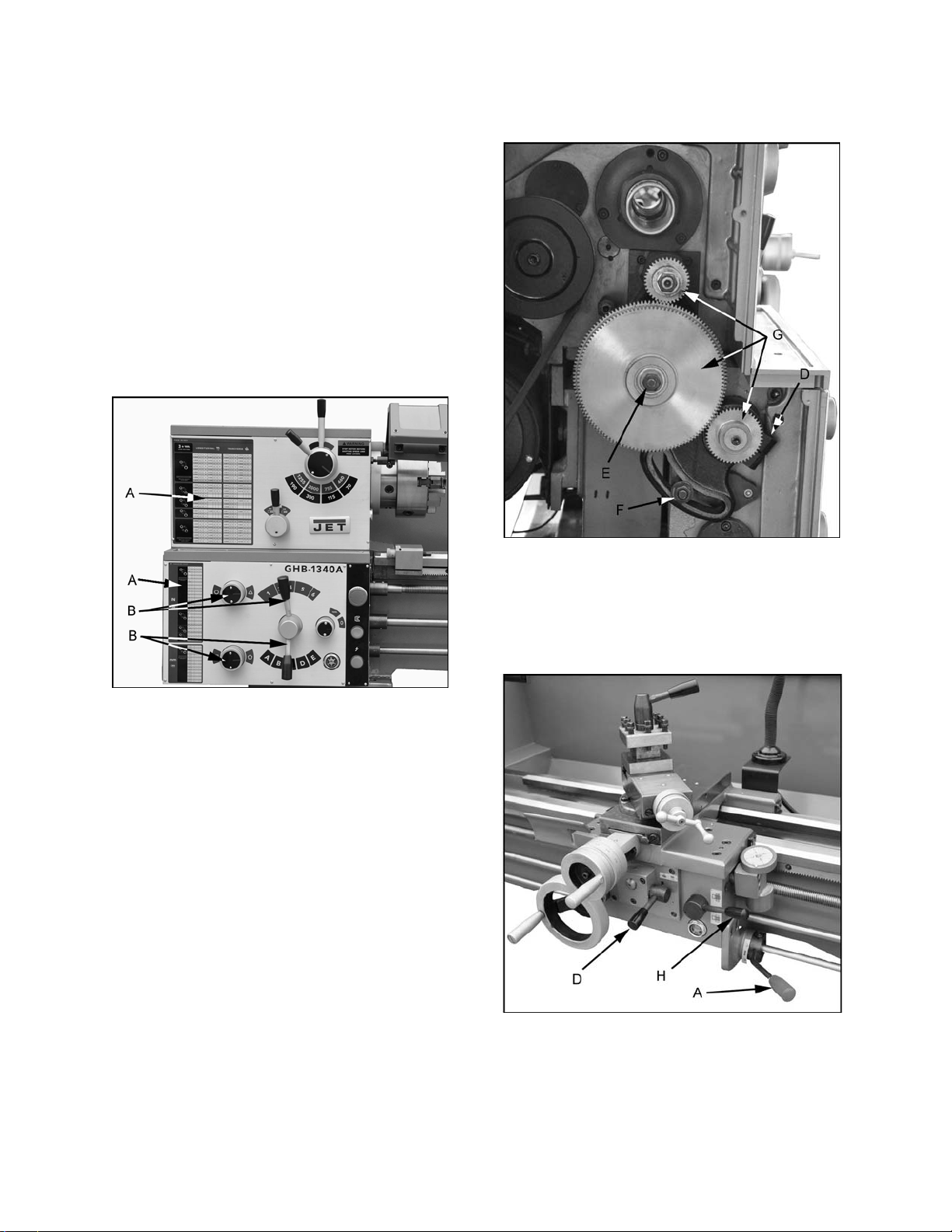
1. Reference the feed and thread table (A, Fig.
16).
2. Move knobs and handle (B, Fig. 16) to the
appropriate position.
Figure 16
12.3 Change Gear Replacement
Note: the 32T x 127T x 48T gears are installed in
the end gear compartment when delivered from the
factory. This combination will cover most inch
feeds and threads under normal circumstances.
The additional gears found in the toolbox are used
for some metric threads and feeds.
1. Disconnect the machine from the power
source.
2. Open the end cover on the left end of the
headstock.
3. Loosen the socket head cap screw (D, Fig. 17)
and hex nuts (E & F, Fig. 17). Move the
quadrant out of the way.
4. Change gears (G, Fig. 17) to match the feed
and thread chart.
5. Thoroughly clean and install new gears.
6. Move the quadrant so the large gear meshes
with the smaller gears and tighten to secure in
place. Note:Make surethere is backlash of
0.002” – 0.003” between gears. Setting the
gears too tight will cause excessive noise and
wear.
7. Close the cover and connect the machine to
the power source.
Figure 17
12.4 Automatic Feed Operation and
Feed Changes
1. Move the forward/reverse selector (A, Fig. 18)
up or down depending on desired direction.
Figure 18
2. Set the selector handle (B, Fig. 19) to the “3”
position and turn knob (C, Fig. 19) counter-
clockwise so the arrow is pointing up to start
the feed rod rotating.
14
Figure 19
12.5 Powered Carriage Travel
Push lever (D, Fig. 18) to the left and down to
engage crossfeed. Pull lever to the right and up to
engage longitudinal feed.
12.6 Thread Cutting
1. Set feed rate selectors (B, E, F, G, Fig. 19) in
proper position for the correct feed rate of the
thread pitch to be cut.
2. Move knob (C, Fig. 19) to the “0” position to
disengage the feed rod.
3. Engage the half nut lever (H, Fig. 18).
4. The half nut lever and the threading dial are
used to thread in the conventional manner.
The thread dial chart specifies at which point a
thread can be entered using the threading dial.
5. To cut metric threads, the half nuts must be
left continually engaged once the start point
has been selected and the half nut is initially
engaged (thread dial cannot be used).
13.0 Adjustments
13.1 Saddle adjustment
1. Loosen four hex nuts (A, Fig. 20) found on the
bottom rear of the cross slide.
2. Turn each of the four set screws (B, Fig.20)
equally with a hex wrench until a slight
resistance is felt. Do not over tighten.
3. Move the carriage with the hand wheel and
determine if drag is to your preference.
Readjust the setscrews as necessary to
achieve the desired drag.
4. Hold socket set screw firmly with a hex wrench
and tighten hex nut to lock in place.
5. Move the carriage again and adjust if
necessary. Note: over adjustment will cause
excessive premature wear of the gibs.
Figure 20
13.2 Cross Slide adjustment
If the cross slide is too loose, follow procedure
below to tighten:
1. Loosen the rear gib screw (C, Fig. 20)
approximately one turn.
2. Tighten front gib screw a quarter turn. Turn the
cross slide handwheel to see if the cross slide
is still loose. If it is still loose, tighten the front
screw a bit more and try again.
3. When cross slide is properly adjusted, snug
rear gib screw. Do not overtighten; this will
cause premature wear on the gib and mating
parts.
13.3 Compound Slide adjustment
Follow the same procedure, as the cross slide
adjustment, to adjust the compound rest.
13.4 Tailstock adjustment
If the handle will not lock the tailstock securely, use
the following procedure:
1. Lower handle to the unlocked position.
2. Slide tailstock to an area that will allow you to
reach under the tailstock.
3. Tighten tailstock clamping nut 1/4 turn, and re-
test for proper locking. Repeat as necessary.
15
13.5 Half Nut Gib adjustment
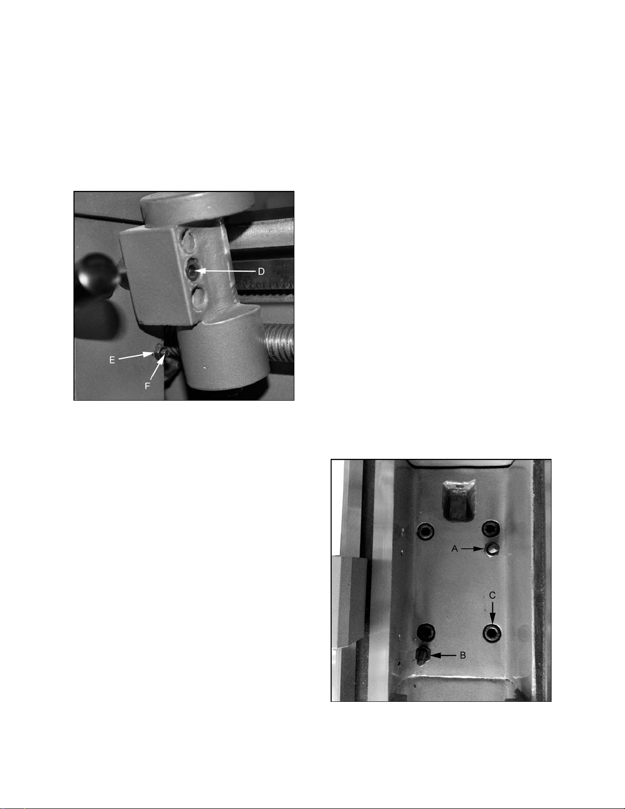
1. Remove the thread dial assembly by
unscrewing the screw (D, Fig. 21).
2. Loosen three hex nuts (E, Fig. 21) found on
the side of apron, and turn three set screws (F,
Fig. 21) equally with a hex wrench.
3. Adjust properly for wear and play. Hold socket
set screw firmly with a hex wrench and tighten
hex nut to lock in place. Note: over
adjustment will cause excessive premature
wear on gib and mating parts.
Figure 21
13.6 Headstock Alignment
The headstock has been aligned at the factory and
should not require adjustment. However, if
adjustment is deemed necessary, follow the
procedure below to align the headstock.
1. Using an engineer's precision level on the
bedways, make sure the lathe is level side to
side and front to back. If the lathe is not level,
correct to a level condition before proceeding.
Re-test alignment if any leveling adjustments
were made.
2. From steel bar stock of approximately two
inches in diameter, cut a piece approximately
eight inches long.
3. Place two inches of bar stock into chuck and
tighten chuck. Do not use the tailstock or
center to support the other end.
4. Set up and cut along five inches of the bar
stock.
5. Using a micrometer, measure the bar stock
next to the chuck and at the end. The
measurement should be the same.
6. If the measurements are not the same and
adjustment is required, loosen the four bolts
that hold the headstock to the bed. Do not
loosen completely; some drag should remain.
7. Loosen two hex nuts found on the two
adjusting bolts located on the backside of
headstock just above the motor mount bracket.
Adjust the bolts for alignment and tighten hex
nuts. Tighten the headstock bolts and make
another cut. Keep adjusting screws after each
cut until the bar stock measurements are the
same. Tighten all headstock bolts and jam
nuts on adjusting screws.
13.7 Removing Gap Bridge
1. Using an open end wrench, tighten the two
hex nuts (A, Fig. 22). This will cause the taper
pins (B, Fig. 22) to release. Remove the taper
pins.
2. Remove the four hex socket cap screws (C,
Fig. 22) with a hex key wrench.
3. Gap bridge can now be removed.
13.8 Installing Gap Bridge
1. Clean the bottom and the ends of the gap
bridge thoroughly.
2. Set gap bridge in place and align.
3. Remove nuts (A, Fig. 22) from the taper pins
(B, Fig. 22).
4. Slide taper pins in their respective holes and
seat using a mallet. Install nuts on the taper
pins finger tight.
5. Install four socket head cap screws (C, Fig. 22)
and tighten securely.
Figure 22
16
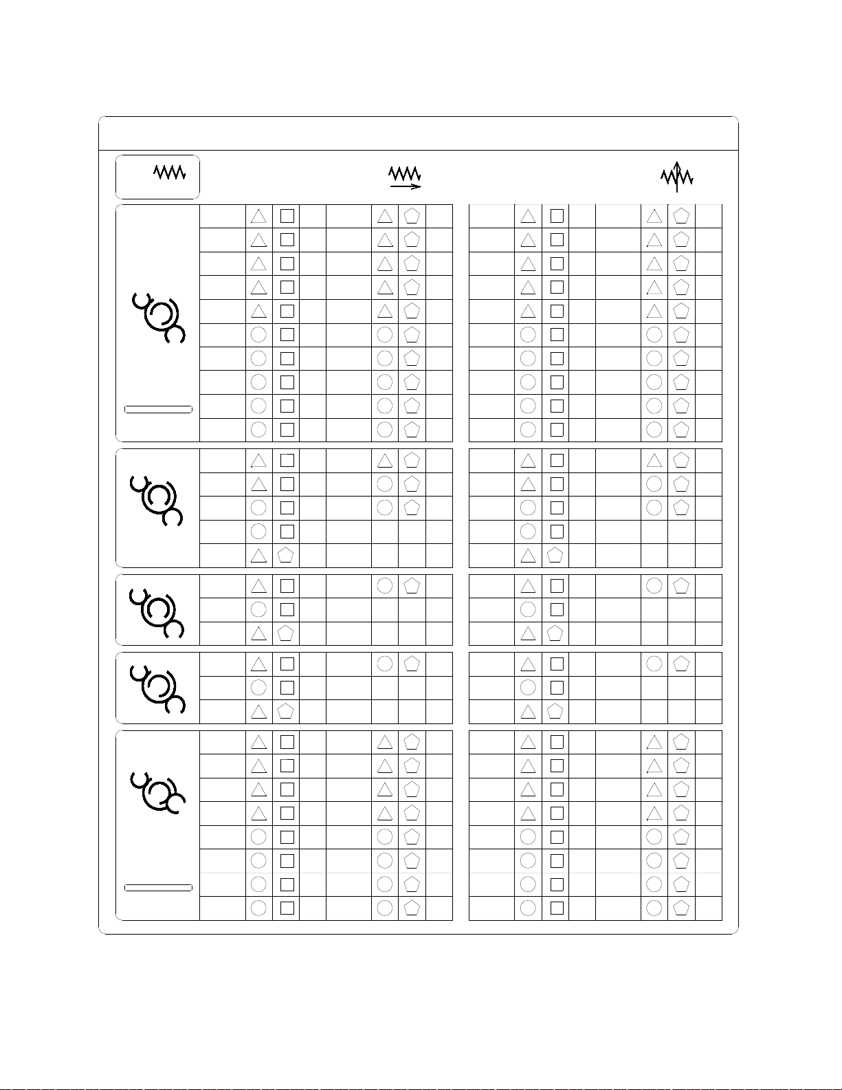
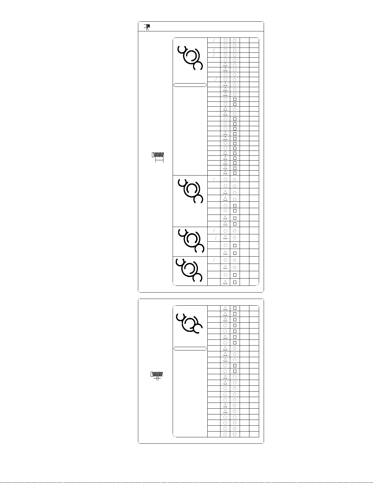
14.0 Thread and Feed Chart
0.0018
0.0020
0.0035
0.0069
A
E
0.0035
0.0037
0.0030
0.0033
B
C
A
0.0139
0.0031 C
0.0061
0.0122
0.0066
C
0.0036
0.0070
D
0.0029
0.0043
B
0.0277
0.0081
C
0.0133
0.0139
D
0.0245
0.0244
B
0.0266
C
F
EED IN/RE
V
0.0104
0.0115
LONGITUDINAL
TRANSVERSE
A
E
B
C
A
E
B
A
E
0.0006
0.0007
0.0011
0.0012
0.0013
0.0014
0.0021
0.0028
0.0048
0.0024
0.0048 C
0.0011
0.0012
0.0021
0.0042
0.0032
C
0.0036 A
0.0095
0.0050
D
D
0.0084
0.0091
0.0096
0.0056
0.0084
0.0040
E
C
0.0023
E
B
C
3+
LEVER POSITIONS
32
48
120
127
A T T E
N T I O
N
Red
circles
represent
stacked
gears
D
0.0278
0.0162
0.0146
A
E
D
0.0041
E
0.0073
A
E
A
0.0041
E
0.0073
0.0081
A
E
0.0146
A
0.0162
0.0292
E
A
0.0325
E
C
C
C
C
C
C
C
48
48
120
127
A T T E
N T I O
N
Red
circles
represent
0.0026
0.0047
0.0052
0.0058
0.0086
0.0093
0.0187
0.0207
0.0173
0.0230
0.0345
0.0374
A
E
C
A
E
B
C
A
C
A
E
B
C
0.0024
0.0025
0.0042
0.0046
0.0010
D
D
B
C
A
0.0012
0.0014
0.0025
0.0028
0.0049
0.0055
0.0099
0.0112
E
E
E
E
A
A
A
A
C
CC
C
C
CC
0.0009
0.0010
0.0015
0.0016
0.0018
0.0020
0.0030
0.0059
0.0065
0.0071
0.0079
0.0119
0.0130
A
E
B
C
A
E
B
B
C
A
E
B
C
0.0061
B
0.0122
B
E
B
44
33
120
127
32
46
120
127
32
52
120
127
17
I N
T.P.I
3
4
5
6D
32
48
120
127
A T T E N T I O N
Red circles represent stacked gears
6
7
8
9
10
10
11
12
14
16
18
20
21
22
24
28
32
36
40
42
44
48
72
80
4
5
9
10
18
20
36
40
5
11
23
46
13
6
26
52
44
33
120
127
6B
6
B
6
B
6
B
2D
2
D
2D
2
D
52
C
2
C
2
C
2C
4
C
4
C
4
C
4
C
6D
6D
6D
2
E
2E
2E
2E
2
A
2A
2A
2
A
2E
2E
2
E
2E
2A
2
A
2
A
2A
4
C
4
C
4
C
4
C
4
C
4
C
4C
4
C
mm
0.45
0.50
0.75
5E
48
48
120
127
1.0
1.25
1.50
1.75
1.80
2.00
2.25
2.50
2.75
3.00
3.50
3.60
4.00
4.50
5.00
5.50
6.00
9.00
10.0
2
E
B
0.90
C
A
5E
2
E
2E
2E
2
A
2
A
2
A
2
4
C
4
C
4
C
4
1
B
1
B1
B1
6B
6
B
6B
4
B
4B
32
46
120
127
32
52
120
127
A T T E N T I O N
Red circles represent stacked gears
1
2
1
4
1
2
1
2
1
2
3
4
1
2
1
2
THREADING CHART

18
This page intentionally left blank.

19
This page intentionally left blank.

20
427 New Sanford Road
LaVergne, Tennessee 37086
Phone: 800-274-6848
www.jettools.com
Parts List and Electrical Diagrams
For Lathe models BDB-1340A, GHB-1340A, GHB-1440A
(GHB-1340A shown)
For GHB-1340A/1440A Operating Instructions, see document M-321357A-1
For BDB-1340A Operating Instructions, see document M-321360A
JET
427 New Sanford Road
LaVergne, Tennessee 37086 Part No. M-321357A
Ph : 800-274-6848 Revision J 05/2016
www.jettools.com Copyright © 2016 JET
This .pdf document is bookmarked

2
Table of contents
Section Page
······················ Table of
contents ·································································································· 2
······················ Replacement parts ········································································································ 3
1.0 ·················· BDB-1340A Headstock Assembly I – Exploded View···························································· 4
1.1 ·················· BDB-1340A Headstock Assembly I – Parts List ································································ 5-6
2.1 ·················· BDB-1340A Headstock Assembly II – Exploded View ··························································· 7
2.2 ·················· BDB-1340A Headstock Assembly II – Parts List ·································································· 8
3.1 ·················· BDB-1340AHeadstockAssemblyIII – Exploded View ···························································· 9
3.2 ·················· BDB-1340AHeadstockAssemblyIII – Parts List ·································································· 10
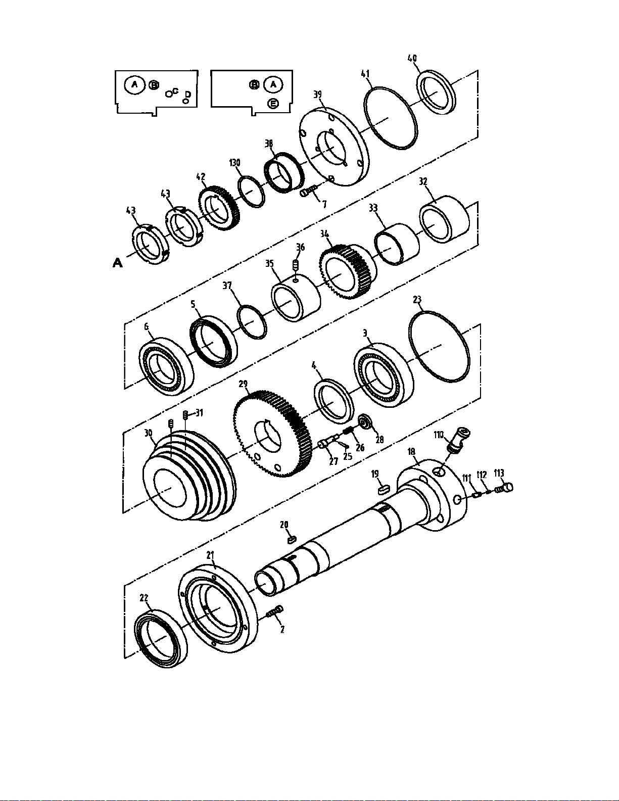
4.1 ·················· GHB-1340A/1440A Headstock Assembly I – Exploded View ················································ 11
4.2 ·················· GHB-1340A/1440AHeadstockAssemblyI – Parts List······················································ 12-13
5.1 ·················· GHB-1340A/1440A Headstock Assembly II – Exploded View ··············································· 14
5.2 ·················· GHB-1340A/1440A Headstock Assembly II – Parts List ······················································ 15
6.1 ·················· GHB-1340A/1440A Headstock Assembly III – Exploded View ·············································· 16
6.2 ·················· GHB-1340A/1440A Headstock Assembly III – Parts List ····················································· 17
7.1 ·················· Bed Assembly I – Exploded View ··················································································· 18
7.2 ·················· Bed Assembly I – Parts List ······················································································· 19-20
8.1 ·················· Bed Assembly II – Exploded View ·················································································· 21
8.2 ·················· Bed Assembly II – Parts List ·························································································· 22
9.1 ·················· Gear Assembly I – Exploded View ·················································································· 23
9.2 ·················· Gear Assembly I – Parts List ····················································································· 24-25
10.1 ················ Gear Assembly II – Exploded View ················································································· 26
10.2 ················ Gear Assembly II – Parts List ························································································ 27
11.1 ················ Gear Assembly III – Exploded View ················································································ 28
11.2 ················ Gear Assembly III – Parts List ························································································ 29
12.1 ················ Apron Assembly I – Exploded View················································································· 30
12.2 ················ Apron Assembly I – Parts List ························································································ 31
13.1 ················ Apron Assembly II – Exploded View ················································································ 32
13.2 ················ Apron Assembly II – Parts List ······················································································· 33
14.1 ················ Apron Assembly III – Exploded View ··············································································· 34
14.2 ················ Apron Assembly III – Parts List ······················································································ 34
15.1 ················ Micro Carriage Stop Assembly – Exploded View ······························································· 35
15.2 ················ Micro Carriage Stop Assembly – Parts List ······································································· 35
16.1 ················ Top Slide, Tool Post, Saddle, and Cross Slide I – Exploded View ········································· 36
16.2 ················ Top Slide, Tool Post, Saddle, and Cross Slide I – Parts List ················································· 37
17.1 ················ Top Slide, Tool Post, Saddle, and Cross Slide II – Exploded View········································· 38
17.2 ················ Top Slide, Tool Post, Saddle, and Cross Slide II – Parts List ············································ 39-40
18.1 ················ Tailstock Assembly I – Exploded View ············································································· 41
18.2 ················ Tailstock Assembly I – Parts List ···················································································· 42
19.1 ················ Tailstock Assembly II – Exploded View ············································································ 43
19.2 ················ Tailstock Assembly II – Parts List ··················································································· 43
20.1 ················ Follow Rest – Exploded View ························································································ 44
20.2 ················ Follow Rest – Parts List ································································································ 44
21.1 ················ Steady Rest – Exploded View ························································································ 45
21.2 ················ Steady Rest – Parts List ······························································································· 46
22.1 ················ GHB-1340A/1440AChuck Guard Assembly – Exploded View ··············································· 47
22.2 ················ GHB-1340A/1440AChuck Guard Assembly – Parts List ······················································ 47
23.0 ················ Additional Parts (Not Shown) ······················································································· 48
24.0 ················ Additional Electrical Components (Not Shown) ································································ 48
25.1 ················ Electrical Schematic – GHB-1340A/1440A ······································································· 49
25.2 ················ Electrical Schematic Parts List – GHB-1340A/1440A ·························································· 49
26.1 ················ Electrical Schematic – BDB-1340A ················································································· 50
26.2 ················ Electrical Schematic Parts List – BDB-1340A ···································································· 50
27.0 ················ GHB-1340A/1440AWiringPhoto ····················································································· 51
28.0 ················ BDB-1340AWiringPhoto ······························································································· 51

3
Replacement parts
To order parts or reach our service department , call1-800-274-6848 Monday through Friday (see our
website
for business hours , www.jettools.com) Having the Model Number and Serial Number of your machine
available
when you call will allow us to serve you quickly and
accurately
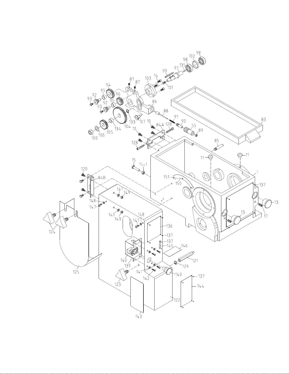
1.0 BDB-1340A Headstock Assembly I – Exploded View
4

1.1 BDB-1340A Headstock Assembly I – Parts List
5
Index Part
No No Description Size Qty
1
..............
04101BG .................. Headstock Casting ................................................... ......................................
1
10
............
TS-1482021 .............. Hex Socket Cap Screw ........................................... M6x12 ...........................
4
11
............
04501A ..................... Inlet
Plug
.................................................................. ......................................
2
13
............ BDB1340-H13
........... Oil Sight
Glass
......................................................... ......................................
2
14
............
TS-1503031 .............. Hex Socket Cap Screw ........................................... M6x12 ...........................
3
15
............
TS-1490061 .............. Hex Cap Bolt ........................................................... M8x35 ...........................
2
15-1 .........
TS-1540061 .............. Nut ...........................................................................
M8
....................................
2
17
............ BDB1340-H17
........... Screw....................................................................... 1/8” ...............................
2
55
............
04733B ..................... Knob ........................................................................ ......................................
1
83
............
04310G ..................... Cover ....................................................................... ......................................
1
84A .........
04723A ..................... Cover
Hinge
............................................................. ......................................
1
84B .........
04723B ..................... End Cover Hinge ..................................................... ...................................... 1
85
............
04705 ........................ Strut ......................................................................... ..........................................
1
86
............
BDB1340A-02118AG
Arm
.......................................................................... ......................................
1
87
............
TS-1523031 .............. Set Screw ................................................................ M6x10 ...........................
2
88
............
04725B ..................... Plunger .................................................................... ......................................
1
89
............ BDB1340-H89
........... Cap Nut.................................................................... ......................................
1
90
............
04734B ..................... Spring Sleeve .......................................................... ......................................
1
91
............ BDB1340-H91
........... Spring ...................................................................... 1x9x50 ..........................
1
92
............
04721 ........................ Idle Shaft.................................................................. ......................................
2
93
............ BDB1340-H93
........... Oil Nipple ................................................................. ......................................
2
94
............
04719 ........................ Gear ........................................................................ 1.5m26T........................
1
95
............
04303 ........................
Bushing
.................................................................... ......................................
2
96
............
04720 ........................ Gear ........................................................................ 1.5m21T........................
1
97
............
BDB1340A-02717A... Output Shaft............................................................. ......................................
1
98
............
BB-6202ZR ............... Ball Bearing ............................................................. 6202ZR .........................
2
99
............
BDB1340A-H99......... Key .......................................................................... 5x5x50 ..........................
1
100
..........
TS-1540081 .............. Hex
Nut
....................................................................
M12
...............................
1
101
.......... BDB1340-H93
........... Oil Nipple ................................................................. ......................................
1
102
..........
04716 ........................ Spacer ..................................................................... ......................................
1
103
..........
04119A .....................
Flange
...................................................................... ......................................
1
104
..........
BDB1340A-02718A... Gear ........................................................................ 1.5m50T........................
1
105
..........
GH1340A-05735 ....... Gear ........................................................................ 1.25m32T......................
1
................
GHB1340A-CG2 ....... Gear ........................................................................ 1.25m48T......................
1
................ GHB1340A-CG1 ....... Gear ........................................................................ 1.25m44T......................
1
106
.......... BDB1340-H106
......... Washer .................................................................... ......................................
1
107
..........
04714 ........................ Bolt .......................................................................... ......................................
1
120
..........
TS-1482021 .............. Cap
Screw
............................................................... M6x12 ...........................
4
121
..........
BDB1340A-02722A... Stud ......................................................................... ......................................
1
122
..........
BDB1340A-02305AG End Cover................................................................ ......................................
1
123
.......... BDB1340-H123
......... Knob ........................................................................ ......................................
1
124
.......... BDB1340-H124
......... Knob ........................................................................ ......................................
2
125
..........
04724G ..................... Cover ....................................................................... ......................................
1
127
..........
BDB1340-H127 ......... Rubber Mat(serial #1509B1613A and lower) ..... ......................................
1
128
..........
TS-1503081 .............. Hex Socket Cap Screw ........................................... M6x35 ...........................
2
129
.......... BDB1340-H129
.........
C-Clip
.......................................................................
8
....................................
1
133
..........
BDB1340A-H133....... C-clip for
Shaft
.........................................................
19
..................................
1
134
..........
BDB1340A-02124 ..... Spacer ..................................................................... ......................................
1
135
..........
BDB1340A-H135....... Plug..........................................................................
5
....................................
1
136
..........
BDB1340A-H136....... Sign Plate(serial #1509B1613A and lower) ........ ......................................
1
................
LM000207 ................. Feed Chart(serial #1604B1614A and higher) ..... ......................................
1
137
.........
BDB1340A-H137 ...... Half Round Cap Screw(serial #1509B1613A and lower)M3x5 .................
8
................
GB267 2-M3x6 ........... Screw(serial #1604B1614A and higher) ............. M3x6 ...........................
14
138
..........
BDB1340A-H138....... Sign Plate(serial #1509B1613A and lower) ........ ......................................
1
................
LM000209 ................. Headstock P late(serial #1604B1614A and higher) ...................................
1

1.1 BDB-1340A Headstock Assembly I – Parts List
6
Index Part
No No Description Size Qty
139
········
BDB1340A-18703 ······ Emergency Stop Housing(serial #1604B1614A and higher) ··············
1
140
········
BDB-SB1 ················· Emergency Stop(serial #1604B1614A and higher)ZB2-BS54C ·········
1
141
········
TS-1550041 ············· Plain Washer(serial #1604B1614A and higher)6mm ·······················
6
142
········
GB2672- M6x8……Hex Lobular Soc Pan Hd Screw(serial #1604B1614A and higher)M6x8 ···
4
143
········
LM000205 .................... Thread Dial Chart(serial #1604B1614A and higher) ························
4
144
········
LM000206 .................... Threading Chart(serial #1604B1614A and higher) ··························
1
145
········
C0632-06306-2 ............ Plate(serial #1604B1614A and higher) ··········································
1
146
········
LM000201 .................... Caution Label – Change Direction(serial #1604B1614A and higher) ··
1
147
········
5512797 ....................... Screw(serial #1604B1614A and higher)M5x25 ·······························
2
148
········
TS-1550031 ................. Plain Washer(serial #1604B1614A and higher)5mm ························
2
149
········
TS-1540031 ................. Hex Nut(serial #1604B1614A and higher)M5 ·································
2
150
········
LM000202 .................... Hi/Lo Label(serial #1604B1614A and higher) ································· 1
151
········
JHM610-151 ................ Rivet(serial #1604B1614A and higher)M2x3 ·································· 3
2.1 BDB-1340A Headstock Assembly II – Exploded View
7

2.2 BDB-1340A Headstock Assembly II – Parts List
8
Index Part
No No Description Size Qty
2
..............
TS-1503051 .............. Hex Socket Cap Screw .......................................... M6x22 ...........................
4
3
..............
BB-30212 .................. Taper Roller Bearing .............................................. 60x110x22 ....................
1
4
.............. BDB1340-H4
............. Oil Seal ................................................................... PG60x80x12 .................
1
5
..............
OS-709012 ............... Oil Seal ................................................................... SG70x90x12 .................
1
6
..............
BB-30211 .................. Taper Roller Bearing .............................................. 55x100x21 ....................
1
7
..............
TS-1503041 .............. Hex Socket Cap Screw .......................................... M6x16 ...........................
4
18
............
04701 ........................
Spindle
..................................................................... D1-4 ..............................
1
19
............ BDB1340-H19
........... Key .......................................................................... 8x7x18 ..........................
1
20
............ BDB1340-H20
........... Key .......................................................................... 6x6x16 ..........................
1
21
............
04102G ..................... Bearing Cover (front) .............................................. ......................................
1
22
............ BDB1340-H22
........... Oil Seal ................................................................... 75x100x12 ....................
1
23
............ BDB1340-H23
........... O-Ring ..................................................................... 125x3.1 .........................
1
25
............ BDB1340-H25
........... Shaft
Pin
................................................................. 3x18 ..............................
1
26
............ BDB1340-H26
........... Spring ...................................................................... 0.8x11x18 .....................
1
27
............
04703 ........................ Pin ........................................................................... ......................................
1
28
............
04702 ........................ Nut ........................................................................... ......................................
1
29
............
04117A ..................... Gear ........................................................................ 2m74T...........................
1
30
............
04116 ........................
Pulley
....................................................................... ......................................
1
31
............
TS-1523031 .............. Set Screw ................................................................ M6x10 ...........................
2
32
............
04302 ........................
Bushing
.................................................................... ......................................
1
33
............
04301 ........................
Bushing
.................................................................... ......................................
1
34
............
04115 ........................ Gear ........................................................................ 2m44T...........................
1
35
............
04114 ........................ Spacer ..................................................................... ......................................
1
36
............
TS-1524021 .............. Set Screw ................................................................ M8x6 .............................
1
37
............ BDB1340-H37
........... O-Ring ..................................................................... 60x3.1 ...........................
1
38
............
04112A ..................... Spacer ..................................................................... ......................................
1
39
............
04113 ........................ Bearing Cover
(rear)
............................................... ......................................
1
40
............ BDB1340-H40
........... Oil Seal ................................................................... W60x80x
8
.....................
1
41
............ BDB1340-H41
........... O-Ring ..................................................................... 110x3.1 .........................
1
42
............
04713 ........................ Gear ........................................................................ 1.5m50T........................
1
43
............
04743 ........................ Locking
Nut
............................................................. ......................................
2
110
..........
04729 ........................ Cam ......................................................................... ......................................
3
111
..........
04741 ........................ Pin ........................................................................... ......................................
3
112
.......... BDB1340-H112
......... Spring ...................................................................... 0.6x4x16 .......................
3
113
..........
TS-1504041 .............. Hex Socket Cap Screw .......................................... M8x18 ...........................
3
130
.......... BDB1340-H130
......... O-Ring ..................................................................... 55x3.1 ..............................
1
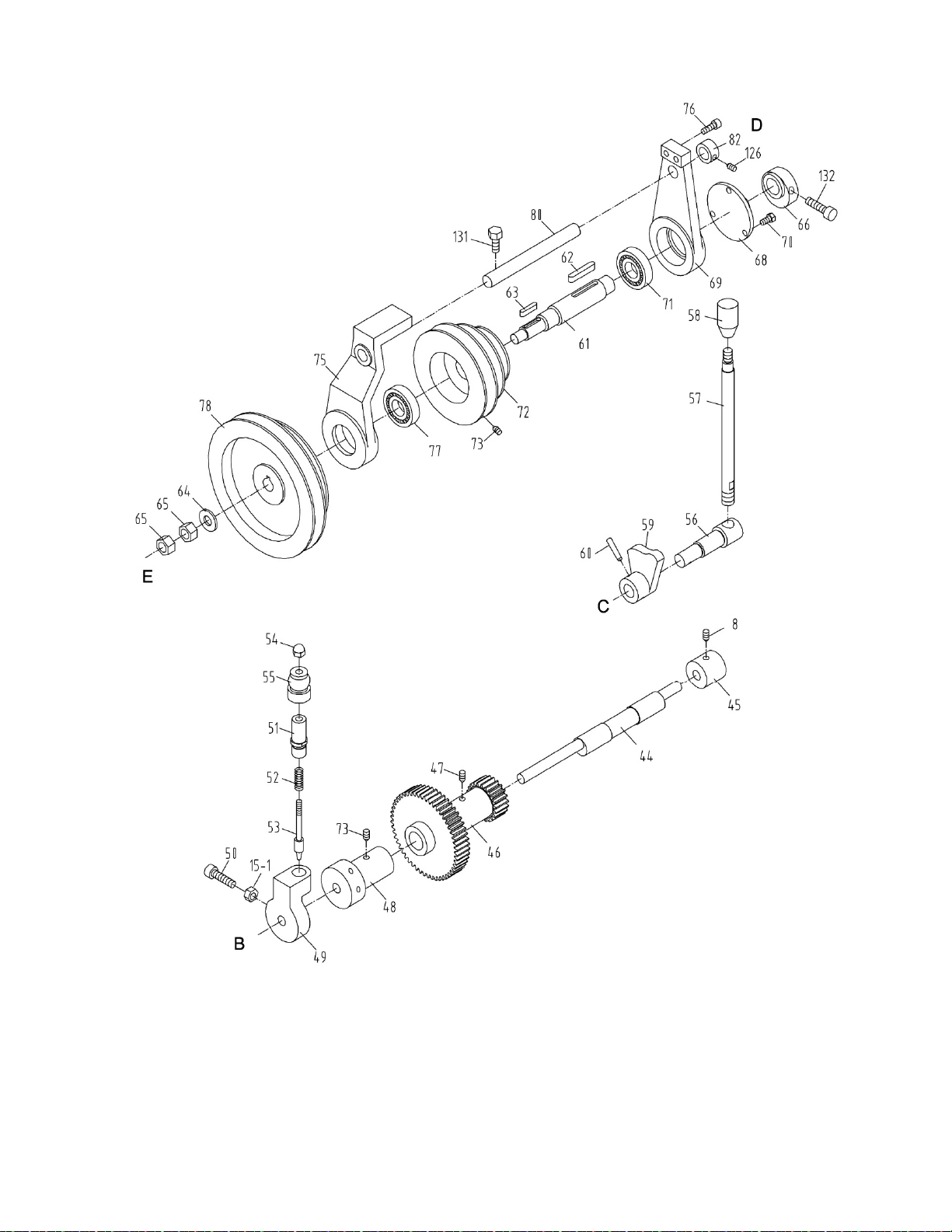
3.1 BDB-1340A Headstock Assembly III – Exploded View
9

3.2 BDB-1340A Headstock Assembly III – Parts List
10
Index Part
No No Description Size Qty
8 .............. TS-1524021 ............... Set Screw ................................................................. M8x10 ........................... 1
15-1 ......... TS-1540061 ............... Nut ........................................................................... M8 ................................. 1
44 ............ 04704 ........................ Eccentric Shaft ......................................................... ...................................... 1
45 ............ 04103A ...................... Bushing .................................................................... ...................................... 1
46 ............ 04109A ...................... Gear ......................................................................... 2m52T,2m22T ............... 1
47 ............ TS-1523011 ............... Set Screw ................................................................. M6x6 ............................. 1
48 ............ 04111A ...................... Bushing .................................................................... ...................................... 1
49 ............ 04110G ...................... Moving Arm .............................................................. ...................................... 1
50 ............ TS-1504071 ............... Hex Socket Cap Screw ............................................ M8x35 ........................... 1
51 ............ 04726 ........................ Sleeve ...................................................................... ...................................... 1
52 ............ BDB1340-H52 ........... Spring ....................................................................... 1x9x40........................... 1
53 ............ 04725 ........................ Shaft ......................................................................... ...................................... 1
54 ............ BDB1340-H54 ........... Cap Nut .................................................................... M6 ................................. 1
55 ............ 04733B ...................... Knob ......................................................................... ...................................... 1
56 ............ 04706 ........................ Shaft ......................................................................... ...................................... 1
57 ............ 04707 ........................ Lever ........................................................................ ...................................... 1
58 ............ BDB1340-H58 ........... Knob ......................................................................... ...................................... 1
59 ............ 04104A ...................... Cam ......................................................................... ...................................... 1
60 ............ BDB1340-H60 ........... Spring Pin ................................................................ 5x30 .............................. 1
61 ............ 04712 ........................ Input Shaft ................................................................ ...................................... 1
62 ............ BDB1340-H62 ........... Key ........................................................................... 6x6x40........................... 1
63 ............ BDB1340-H63 ........... Key ........................................................................... 5x5x25........................... 1
64 ............ TS-1550081 ............... Washer ..................................................................... M12 ............................... 1
65 ............ TS-1540081 ............... Hex Nut .................................................................... M12 ............................... 2
66 ............ 04708 ........................ Cam ......................................................................... ...................................... 1
68 ............ 04709 ........................ Strut ......................................................................... ...................................... 1
69 ............ 04105A ...................... Swing Arm ................................................................ ...................................... 1
70 ............ TS-1482021 ............... Hex Socket Cap Screw ............................................ M6x12 ........................... 3
71 ............ BB-6204ZR ................ Ball Bearing .............................................................. 6204ZR ......................... 1
72 ............ 04107 ........................ Pulley ....................................................................... ...................................... 1
73 ............ TS-1524021 ............... Set Screw ................................................................. M8x8 ............................. 2
75 ............ 04106A ...................... Swing Arm ................................................................ ...................................... 1
76 ............ TS-1503051 ............... Hex Socket Cap Screw ............................................ M6x20 ........................... 2
77 ............ BB-6204 .................... Ball Bearing .............................................................. 6204 .............................. 1
78 ............ BDB1340A-04108 ..... Pulley ....................................................................... ...................................... 1
80 ............ 04711 ........................ Shaft ......................................................................... ...................................... 1
82 ............ 04710 ........................ Spacer ...................................................................... ...................................... 1
126 .......... TS-1523011 ............... Set Screw ................................................................. M6x6 ............................. 1
131 .......... TS-1490041 ............... Hex Cap Bolt ............................................................ M8x25 ........................... 1
132 .......... TS-1504041 ............... Hex Socket Cap Screw ............................................ M8x20 ........................... 1
................ BDB1340A-02311 ..... Nameplate (not shown) ............................................ ...................................... 1
................ BDB1340A-02304A ... Nameplate (not shown) ............................................ ...................................... 1
................ 04308 ........................ Nameplate (not shown) ............................................ ...................................... 1
................ VB-B32 ...................... V-Belt (not shown) ................................................... B32 ................................ 1
................ VB-B33 ...................... V-Belt (not shown) ................................................... B33 ................................ 1
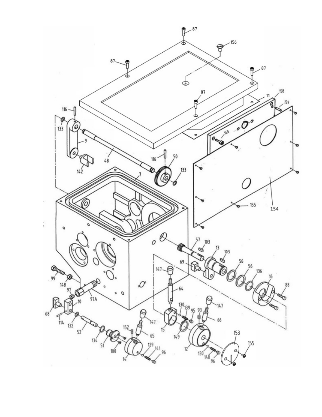
4.1 GHB-1340A/1440A Headstock Assembly I – Exploded View
11

4.2 GHB-1340A/1440A Headstock Assembly I – Parts List
12
Index Part
No No Description Size Qty
7
..............
GHB1340A-02101G .. Gear Box Main Casting (GHB-1340A only)
............ ...................................... 1
................
GHB1440A-02101G .. Gear Box Main Casting (GHB-1440A only)
............ ...................................... 1
9
..............
04109 ........................ Shift Lever ................................................................ ......................................
1
10
............
04111 ........................ Shaft Housing........................................................... ......................................
1
11
............
GHB1340A-02102G .. Cover (GHB-1340A only) ......................................... ......................................
1
................
GHB1440A-02102G .. Cover (GHB-1440A only) ......................................... ......................................
1
12
............
GHB1340A-04117G .. Handle
Hub
.............................................................. ......................................
1
13
............
04121 ........................ Shaft Collar (GHB-1340A only) ................................ ......................................
1
................
GHB1440A-02112 ..... Shaft Collar (GHB-1440A only) ................................ ......................................
1
14
............
GHB1340A-04120G .. Handle
Hub
.............................................................. ......................................
1
15
............
GHB1340A-04119G .. Handle Block ............................................................ ......................................
1
16
............
GHB1340A-04118G .. Hub .......................................................................... ......................................
1
48
............
04232 ........................ Shaft ......................................................................... ......................................
1
50
............
04234 ........................ Gear ......................................................................... 1.25m51T ......................
1
51
............
04235 ........................ Collar (GHB-1340A
only)
......................................... ......................................
1
................
GHB1440A-02709 ..... Collar (GHB-1440A
only)
......................................... ......................................
1
52
............
04250 ........................ Shaft (GHB-1340A
only)
.......................................... ......................................
1
................
GHB1440A-02708 ..... Shaft (GHB-1440A
only)
.......................................... ..........................................
1
56
............
04240 ........................ Washer ..................................................................... ......................................
2
57
............
04241 ........................ Gear Shaft (GHB-1340A
only)
................................. 1.25m17T ......................
1
................
GHB1440A-02716 ..... Gear Shaft (GHB-1440A
only)
................................. 1.25m17T ......................
1
64
............
GHB1340A-04248G .. Handle ...................................................................... ......................................
1
65
............
GHB1340A-04248-1G Handle ...................................................................... ......................................
1
66
............
GHB1340A-04249G .. Handle ...................................................................... ......................................
1
68
............
04402 ........................ Shift Fork .................................................................. ......................................
1
69
............
04403 ........................ Shift Fork .................................................................. ......................................
1
78
............
GHB1340-4506 ......... Gasket ...................................................................... ......................................
1
87
............
TS-1503051 ............... Hex Socket Cap Screw ............................................ M6x20 ...........................
4
88
............
TS-1503061 ............... Hex Socket Cap Screw ............................................ M6x25 ...........................
2
93
............
TS-1523061 ............... Set Screw ................................................................. M6x18 ...........................
1
95
............
TS-1524011 ............... Set Screw ................................................................. M8x8 .............................
1
96
............
TS-1523041 ............... Set Screw ................................................................. M6x12 ...........................
2
97
............
GHB1340A-97 ........... Plug .......................................................................... Z1/4 ..................................
1
97A ..........
GHB1340A-97A ......... Oil Drain Plug ........................................................... ......................................
1
99
............
TS-1490081 ............... Hex Cap Screw ........................................................ M8x45 ...........................
2
100
..........
GHB1340-100 ........... Screw ....................................................................... M4x8 ................................
4
103
..........
GHB1340-103 ........... Key ........................................................................... 5x15 ..............................
2
114
..........
GHB1340-114 ........... Pin ............................................................................ 4x18 ..............................
1
116
..........
GHB1340-116 ........... Pin ............................................................................ 5x30 ..............................
2
129
..........
SB-5MM .................... Steel Ball ..................................................................
5mm
..............................
1
130
..........
SB-6MM .................... Steel Ball ..................................................................
6mm
..............................
2
132
..........
GHB1340-132 ........... O-Ring ...................................................................... 10x
1.9
...........................
1
133
..........
GHB1340-133 ........... O-Ring ...................................................................... 14x
2.4
...........................
2
134
..........
GHB1340-134 ........... O-Ring ...................................................................... 20x
2.4
...........................
2
136
..........
GHB1340-136 ........... O-Ring ...................................................................... 30x
3.1
...........................
1
139
..........
GHB1340-139 ........... S pring ....................................................................... 1x6x7.............................
1
140
..........
GHB1340-140 ........... S pring ....................................................................... 1x6x20...........................
1
141
..........
GHB1340-141 ........... Spring ....................................................................... 0.9x4.4x20.....................
1
142
..........
04235A ...................... Shift Fork .................................................................. ......................................
1
147
..........
GHB1340-147 ........... Knob ......................................................................... M8x40 ...........................
3
148
..........
TS-1540061 ............... Nut ...........................................................................
M8
....................................
2
149
..........
GHB1340-120 ...........
C-Clip
.......................................................................
30mm
............................
1
152
..........
TS-1523041 ............... Set Screw ................................................................. M6x12 ...........................
1
153
..........
GHB1340A-153 ......... Round Sign
Plate
(serial #16013258A and lower) ......................................
1
................
GHB1340A-02303-2 .. Round Sign
Plate
(serial #16043259A and higher) .....................................
1
154
.........
GHB1340A-02301 ..... Headstock Label (GHB-1340A only)(serial #16013258A and lower) .........
1

4.2 GHB-1340A/1440A Headstock Assembly I – Parts List
13
Index Part
No No Description Size Qty
................
LM000209 ................. Headstock Label (GHB-1340A only)(serial #16043259A and higher) ........
1
................ GHB1440A-02301-15
Headstock Label (GHB-1440A only)(serial #16013258A and lower) .........
1
................
LM000212 ................. Headstock Label (GHB-1440A only)(serial #16043259A and higher) ........
1
155
.........
GHB1340A-155 ......... Screw(serial #16013258A and lower) ................. M3x5 .............................
8
................
GB2672-M3x6 ........... Screw(serial #16043259A and higher) ................ M3x6 .............................
8
156
..........
GHB1340A-156 ......... Screw ....................................................................... M10x18 .........................
1
157
..........
GHB1340A-02502 ..... Rubber Mat (GHB-1340A only)(serial #16013258A and lower) .................
1
................
GHB1440A-02503 ..... Rubber Mat (GHB-1440A only)(serial #16013258A and lower) .................
1
158
..........
GHB1440A-02102G .. Headstock Side Board (GHB-1440A only) ............... ......................................
1
159
.......... ZX-S13
...................... Taper Pin (GHB-1440A only) ................................... 5x20mm ........................
2
160
..........
TS-1503041 ............... Hex Socket Cap Screw (GHB-1440A only) M6x16.. ......................................
4
................
GHB1340A-160 ......... Oil Sight Glass (not shown)
(GHB-1340A serial #10052363A and lower)
.........
1
................
GHB1340A-160 ......... Oil Sight Glass (not shown)
(GHB-1440A serial #08040097C and lower)
.........
1
................
GHB1340A-160M ...... Oil Sight Glass (not shown)
.................................... M27x1 5
.........................
1
(GHB-1340A serial #10102364A and higher)
................
GHB1340A-160M ...... Oil Sight Glass (not shown) ....................................
M27x1 5
......................... 1
(GHB-1440A serial #10110098C and higher)
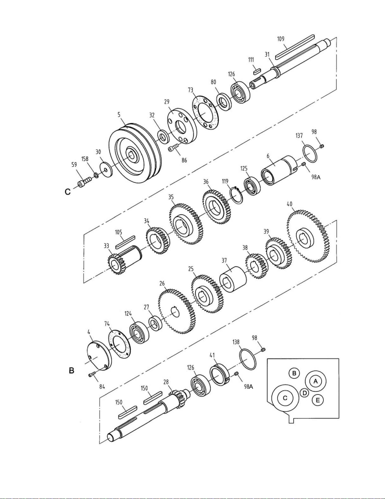
5.1 GHB-1340A/1440A Headstock Assembly II – Exploded View
14

5.2 GHB-1340A/1440A Headstock Assembly II – Parts List
15
Index Part
No No Description Size Qty
4
.............. 04104Z
...................... Rear Cover ............................................................... ......................................
1
5
..............
04105 ........................
Pulley
....................................................................... ......................................
1
6
..............
GHB1340-4106 ......... Plug .......................................................................... ......................................
1
25
............
04209 ........................ Gear ......................................................................... 2m43T ...........................
1
26
............
GHB1340-4210 ......... Gear ......................................................................... 2m51T ...........................
1
27
............
04211 ........................ Spacer...................................................................... .....................................
1
28
............
04212 ........................ Gear Shaft ................................................................ 2.25m16T ......................
1
29
............
04213A ...................... Cover ....................................................................... ......................................
1
30
............
04214 ........................ Washer ..................................................................... ......................................
1
31
............
04215 ........................ Shaft ......................................................................... ......................................
1
32
............
04216 ........................ Washer ..................................................................... ......................................
1
33
............
04217 ........................ Collar w/Gear ........................................................... 2m21T ...........................
1
34
............
04218 ........................ Gear ......................................................................... 2m29T ...........................
1
35
............
04219 ........................ Gear ......................................................................... 2m46T ...........................
1
36
............
04220 ........................ Gear ......................................................................... 2m38T ...........................
1
37
............
04221 ........................ Collar ........................................................................ ......................................
1
38
............
04222 ........................ Gear ......................................................................... 2m26T ...........................
1
39
............
04223 ........................ Gear ......................................................................... 2m34T ...........................
1
40
............
04224 ........................ Gear ......................................................................... 2.25m53T ......................
1
41
............
04225 ........................ Plug .......................................................................... ......................................
1
59
............
TS-1504041 ............... Socket Head Cap Screw .......................................... M8x20 ...........................
1
73
............
GHB1340-4501 ......... Gasket ...................................................................... ......................................
1
74
............
GHB1340-4502 ......... Gasket ...................................................................... ......................................
1
80
............
GHB1340-4508 ......... Oil Seal .................................................................... 20x40 ............................
1
84
............
TS-1501041 ............... Hex Socket Cap Screw ............................................ M4x12 ...........................
3
86
............
TS-1503031 ............... Hex Socket Cap Screw ............................................ M6x12 ...........................
3
98
............
TS-1523031 ............... Set Screw ................................................................. M6x8 .............................
2
98A ..........
GH-1440K02752 ....... Screw ....................................................................... ......................................
2
105
..........
GHB1340-105 ........... Key ........................................................................... 5x50 ..............................
1
109
..........
GHB1340-109 ........... Key ........................................................................... 6x120 ............................
1
111
..........
GHB1340-111 ........... Key ........................................................................... 5x20 ..............................
1
119
..........
GHB1340-119N .........
C-Clip
.......................................................................
35
..................................
1
124
..........
GHB1340-124 ........... B earing ..................................................................... 20x47x14.......................
1
125
..........
GHB1340-125 ........... B earing ..................................................................... 17x40x12.......................
1
126
..........
GHB1340-126 ........... B earing ..................................................................... 20x47x14.......................
2
137
..........
GHB1340-137 ........... O-Ring ...................................................................... 40x
3.1
...........................
1
138
..........
GHB1340-138 ........... O-Ring ...................................................................... 47x
3.1
...........................
1
150
..........
GHB1340A-150 ......... Key ........................................................................... 6x55 ..............................
2
158
..........
TS-1551061 ............... Lock Washer ............................................................
M8
.................................
1
................
VB-A31 ...................... V-Belt (not shown) (GHB-1340A only) ..................... A31 ................................
2
................
VB-A31 ...................... V-Belt (not shown) (GHB-1440A only) ..................... A813 ..............................
2
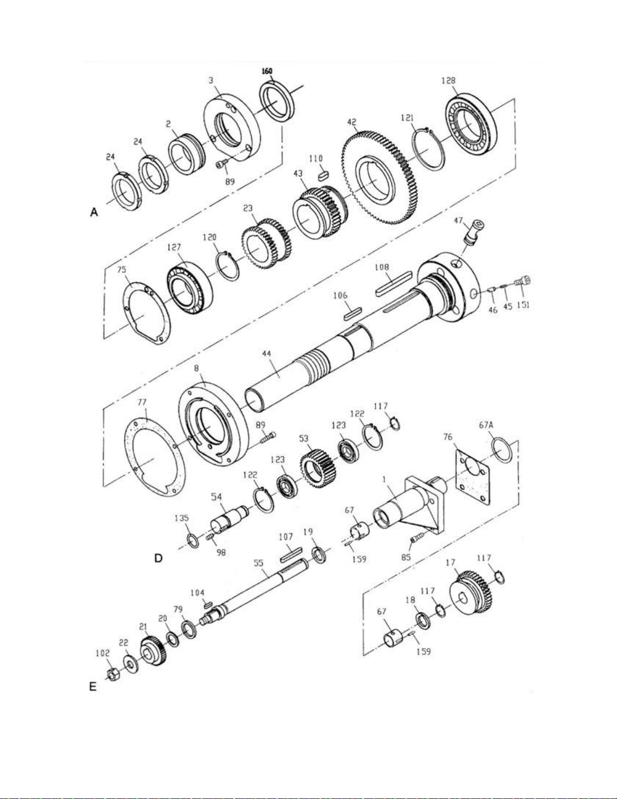
6.1 GHB-1340A/1440A Headstock Assembly III – Exploded View
16

6.2 GHB-1340A/1440A Headstock Assembly III – Parts List
17
Index Part
No No Description Size Qty
1
..............
GHB1340A-02103N... Collar ........................................................................ ......................................
1
2
.............
04102 ........................ Collar (serial #07061677A and lower) ...................... ......................................
1
................
C0632A-02117A ........ Collar (serial #07061678A and higher) .................... ......................................
1
3
.............
GHB1340-4103N ....... Rear Cover (serial #07061677A and lower) ............. ......................................
1
................
C0632A-02115A ........ Rear Cover (serial #07061678A and higher) ........... ......................................
1
8
.............. 04108ZG
................... Front Cover ............................................................. ......................................
1
17
............
04201 ........................ Gear ......................................................................... 2m37T ...........................
1
18
............ 04202Z
...................... Spacer ..................................................................... ......................................
1
19
............ 04203Z
...................... Spacer ..................................................................... ......................................
1
20
............
04204 ........................ Washer ..................................................................... ......................................
1
21
............
04205A ...................... Gear ......................................................................... 1.25m32T ......................
1
22
............
04206 ........................ Washer .....................................................................
12
..................................
1
23
............
04207A ...................... Gear ......................................................................... 2m 37T ...........................
1
24
............
04208 ........................ Lock Nut ................................................................... ......................................
2
42
............
04226 ........................ Gear ......................................................................... 2.25m74T ......................
1
43
............
04227 ........................ Gear ......................................................................... 2.25m37T ......................
1
44
............
GHB1340A-02702 .....
Spindle
..................................................................... ......................................
1
45
............
04229 ........................ Spring ...................................................................... 0.6x4x16........................
3
46
............
04230 ........................ Pin ............................................................................ .....................................
3
47
............
04231 ........................ Cam ......................................................................... ......................................
3
53
............
04237 ........................ Gear ......................................................................... 2m30T ...........................
1
54
............
04238 ........................ Shaft ......................................................................... .....................................
1
55
............
GHB1340A-02701N .. Shaft ......................................................................... ......................................
1
67
............
04401 ........................ Collar ........................................................................ ...................................
2
67A ..........
GHB1340-67A ...........
O-ring
....................................................................... 32x3.1 ...........................
1
75
............
GHB1340-4503 ......... Gasket ...................................................................... .....................................
1
76
............
GHB1340A-02501N .. Gasket ...................................................................... ......................................
1
77
............
GHB1340-4505 ......... Gasket ...................................................................... ......................................
1
79
............
GB-13871-B-22
x35x7
Oil Seal ....................................................................
B-22x35x7
.....................
1
85
............
TS-1502041 ............... Hex Socket Cap Screw ............................................ M5x16 ...........................
4
89
............
TS-1503061 ............... Hex Socket Cap Screw ........................................... M6x25 ...........................
7
98
............
TS-1523031 ............... Set Screw ................................................................. M6x8 .............................
1
102
..........
TS-1540081 ............... Hex
Nut
....................................................................
M12
...............................
1
104
..........
GHB1340-104 ........... Key ........................................................................... 5x18 .............................
1
106
..........
GHB1340-106 ........... Key ........................................................................... 6x40 ..............................
1
107
..........
GHB1340-107 ........... Key ........................................................................... 6x50 ..............................
1
108
..........
GHB1340-108 ........... Key ........................................................................... 8x85 ..............................
1
110
..........
GHB1340-110 ........... Key ........................................................................... 8x18 ..............................
1
117
..........
GHB1340-117N .........
C-Clip
.......................................................................
20
..................................
2
120
..........
GHB1340-120 ...........
C-Clip
.......................................................................
50
..................................
1
121
..........
GHB1340-121 ...........
C-Clip
.......................................................................
72
..................................
1
122
..........
GHB1340-122 ...........
C-Clip
.......................................................................
42
..................................
2
123
..........
GHB1340-123 ........... B earing ..................................................................... 20x42x8.........................
2
127
..........
GHB1340-127 ........... Bearing .................................................................... 50x90x20.......................
1
128
..........
GHB1340-128 .......... Bearing .................................................................... 60x110x22.....................
1
135
..........
GHB1340-135 ........... O-Ring ...................................................................... 25x
2.4
...........................
1
151
..........
GHB1340A-151 ......... Hex Socket Cap Screw ........................................... M8x18 ..........................
3
159
..........
GHB1340A-159 ......... Pin ............................................................................ 2x16 ..............................
2
160
.......... GB13871-B-60x80x8
. Oil Seal (serial #07061678A and higher) .................
B-60x80x8
.....................
1
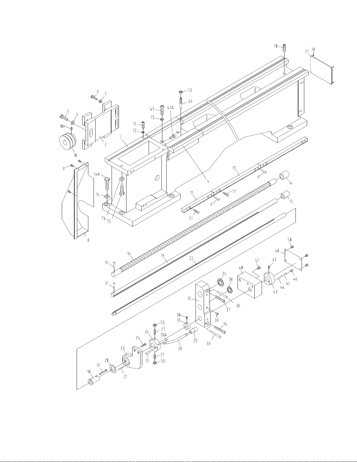
7.1 Bed Assembly I – Exploded View
18

7.2 Bed Assembly I – Parts List
19
Index Part
No No Description Size Qty
1
..............
GHB1340A-01101G .. Bed........................................................................... ......................................
1
2
..............
GHB1340-MPG ......... Motor Base (For GHB) ............................................. ......................................
1
................
BDB1340-MPG .......... Motor Base (For BDB) ............................................. ......................................
1
3
..............
TS-1550071 ............... Washer .....................................................................
M10
...............................
3
4
..............
GHB1340-1102G ....... Gap Bridge ............................................................... ......................................
1
5
..............
TS-1491051 ............... Hex Cap Bolt ............................................................ M10x35 .........................
3
6
..............
TS-1490041 ............... Hex Cap Bolt ............................................................ M8x25 ..............................
4
7
..............
TS-1550061 ............... Washer ..................................................................... ......................................
4
8
..............
GHB1340A-02703G .. End Cover (GHB-1340A only) .................................. .....................................
1
................
GHB1440A-02703G .. End Cover (GHB-1440A only) .................................. .....................................
1
9
..............
GHB1340A-9B ........... Screw ....................................................................... M5x
8
.............................
3
10
............
GHB1340-MP ............
Pulley
(For GHB)...................................................... 28mm ID........................
1
................
BDB1340-MP ............
Pulley
(For BDB) ...................................................... 19mm ID........................
1
10A ..........
TS-1523041 ............... Set Screw ................................................................. M6x12 ...........................
1
11
............
01203 ........................ Rack ......................................................................... ......................................
1
12
............
GHB1340A-12B ......... P in ............................................................................ 5x35mm ........................
2
13
............ 01204-2
..................... Rack ......................................................................... .....................................
2
14
............
32A1105 .................... Collar ........................................................................ ......................................
1
15
............
32A1106 .................... Collar ........................................................................ ......................................
1
16
............
GHB1340A-1701 ....... Lead Screw .............................................................. GHB-1340A ...................
1
................
BDB1340A-1701 ....... Lead Screw ..............................................................
BDB-1340A
.....................
1
17
............
321728 ...................... Key ........................................................................... ......................................
1
18
............
321706 ...................... Collar ........................................................................ .....................................
1
19
............
GHB1340A-1702 ....... Feed
Rod
................................................................. GHB-1340A ...................
1
................
BDB1340A-1702 ....... Feed
Rod
.................................................................
BDB-1340A
...................
1
20
............
01707 ........................ Brake
Ring
............................................................... .....................................
1
21
............
GHB1340A-21B ......... S pring ....................................................................... 1x7.5x25........................
3
22
............
GHB1340A-1703 ....... Shaft ......................................................................... GHB-1340A ...................
1
................
BDB1340A-1703 ....... Shaft.........................................................................
BDB-1340A
...................
1
23
............
32A1103AG ............... Bracket ..................................................................... .....................................
1
24
............
TS-1503061 ............... Hex Socket Cap Screw ........................................... M6x22 ...........................
4
25
............
GHB1340A-25B ......... P in ............................................................................ 6x25mm ........................
1
26
............
32A1710 .................... Handle
Hub
.............................................................. ......................................
1
27
............
TS-1524061 ............... Screw ....................................................................... M8x28 ...........................
2
28
............
01710A ...................... Handle ...................................................................... ......................................
1
28A ..........
GHB1340A-77 ........... Pin ............................................................................ 3x10 ..............................
1
29
............
GHB1340A-29B ......... K nob ......................................................................... BM10x50 .......................
1
30
............
TS-1522031 ............... Set Screw ................................................................. M5x8 .............................
1
31
............
01708 ........................ Collar ........................................................................ .....................................
1
32
............
32A1104AG ............... Bracket ..................................................................... ......................................
1
33
............
GHB1340A-33B ......... Pin ............................................................................ 6x70 ..............................
1
34
............
TS-1504131 ............... Hex Socket Cap Screw ............................................ M8x65 ...........................
1
35
............
32A1502 .................... Plug .......................................................................... ......................................
1
36
............
GHB1340A-36B ......... Pin ............................................................................ 6x65 ..............................
2
37
............
TS-1504121 ............... Hex Socket Cap Screw ............................................ M8x60 ...........................
2
38
............
32A1502 .................... Plug .......................................................................... ......................................
1
39
............
GHB1340A-39B ......... Oil Ba ll ......................................................................
8mm
..............................
3
40
............
32A1301G ................. Switch
Box
.............................................................. ......................................
1
41
............
TS-1504041 ............... Hex Socket Cap Screw ............................................ M8x20 ...........................
4
42
............
TS-1523051 ............... Screw ....................................................................... M6x16 ...........................
1
43
............
32A1705 ....................
Bushing
.................................................................... ......................................
1
44
............
SB-6MM .................... Steel Ball ..................................................................
6mm
..............................
1
45
............
GHB1340A-45B ......... Spring .......................................................................
1X5X22
.........................
1
46
............
TS-1524041 ............... Screw ....................................................................... M8x16 ...........................
1
47A ..........
TS-1525021 ............... Set Screw ................................................................. M10x12 .........................
1
48
............
32A1504 .................... Switch Box Cover..................................................... ......................................
1
49
............
TS-1505051 ............... Hex Socket Cap Screw ........................................... M10x35 .......................... 4

7.2 Bed Assembly I – Parts List
20
Index Part
No No Description Size Qty
50
............
TS-1502021 .............. Socket Head Cap Screw .......................................... M5x10 ...........................
4
51
............
TS-1503061 ............... Hex Socket Cap Screw ............................................ M6x25 ...........................
8
53
............
TS-1540061 ............... Hex
Nut
....................................................................
M8
.................................
4
54A ..........
TS-1492061 ............... Hex Cap Bolt ............................................................ M12x60 .........................
6
61
............
GHB1340-61B ........... Pin ............................................................................ 6x30 ..............................
6
69
............
GHB1340-69B ........... Pin ............................................................................ 8x60 ..............................
2
70
............
GHB1340A-74B ......... S et Screw ................................................................. M12x40 .........................
1
71
............
TS-1505051 ............... Hex Socket Cap Screw (For BDB) .......................... M10x35 (BDB) ..............
2
................
TS-1505061 ............... Hex Socket Cap Screw (For GHB) .......................... M10x40
(GHB)
..............
2
72
............
TS-1551071 ............... Lock Washer ............................................................
10mm
............................
4
73
............
TS-1551071 ............... Lock Washer ............................................................
10mm
............................
4
74
............
TS-1550071 ............... Washer ..................................................................... 10mm ............................
2
75
............
TS-1505071 ............... Hex Socket Cap Screw ............................................ M10x45 .........................
2
76
............
TS-2360121 ............... Washer .....................................................................
12mm
............................
6
77
............
LM000211 .................. Label-Induction Hardened(serial #16043259A and higher) .......................
1
78
............
JHM610-151 .............. Rivet(serial #16043259A and higher) .................
2
x
3mm
..........................
4
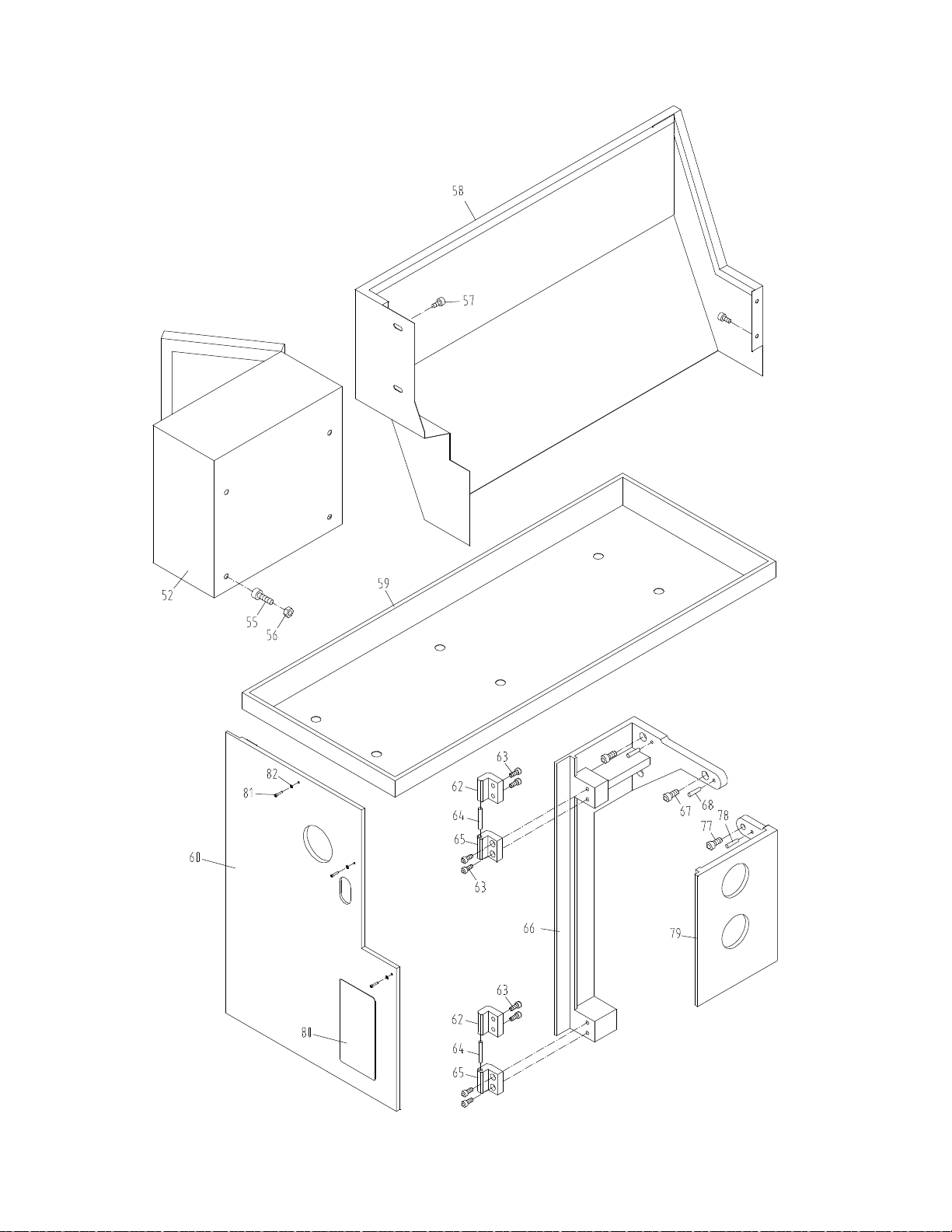
8.1 Bed Assembly II – Exploded View
21

8.2 Bed Assembly II – Parts List
22
Index Part
No No Description Size Qty
52
............
GHB1340A-18701G .. Electrical
Box
(For GHB) ......................................... GHB-1340A ...................
1
................
BDB1340A-18701G ... Electrical
Box
(For BDB) ..........................................
BDB-1340A
...................
1
55
............
GHB1340A-55B ......... S crew ....................................................................... M6x20 ...........................
4
56
............
GHB1340A-56B ......... Nut ...........................................................................
M6
.................................
4
57
............
GHB1340A-57B ......... S crew ....................................................................... M6x10 ...........................
4
58
...........
GHB1340A-12701 ..... Splash Guard(serial #11072601A and lower) .....
GHB-1340A
...................
1
................
GHB1340A-12701A ... S pla sh G uard(serial #11082602A and lower) .....
GHB-1340A
...................
1
................
GHB1340A-12701AG Splash Guard ...........................................................
GHB-1340A
...................
1
................
GHB1440A-12701G .. Splash
Guard
........................................................... GHB-1440A ...................
1
................
BDB1340A-12701BG Splash
Guard
...........................................................
BDB-1340A
...................
1
59
...........
GHB1340A-01701 ..... Oil Plate(serial #12042866A and lower) .............. GHB-1340A ...................
1
................
GHB1340A-01701BJ . Oil Plate(serial #12092867A and lower) .............. GHB-1340A ...................
1
................
GHB1340A-01701BJG….Oil Plate .............................................................. GHB-1340A ...................
1
................
C0632-01727G .......... Oil Plate ................................................................... GHB-1440A ...................
1
................
BDB1340A-01701B ... Oil Plate(serial #1204B1274A and lower) ...........
BDB-1340A
...................
1
................
BDB1340A-01701BJ . Oil Plate(serial #1205B1275A and lower) ...........
BDB-1340A
...................
1
................
BDB1340A-01701BJG…Oil Plate ...............................................................
BDB-1340A
...................
1
60
............
GHB1340A-02302G .. Back Cover .............................................................. GHB-1340A ...................
1
................ C0636A-01501G
....... Back Cover .............................................................. GHB-1440A ...................
1
62
............
ZX-8712 ..................... Upper Hinge ............................................................. ......................................
2
63
............
TS-1503041 ............... Hex Socket Cap Screw ............................................ M6x14 ...........................
8
64
............
GHB1340A-64B ......... P in ............................................................................ 10m 6x40 .......................
2
65
............
ZX-8711 ..................... Lower Hinge ............................................................. .....................................
2
66
............
GHB1340A-02105G .. Rear Side Plate ........................................................ GHB-1340A ...................
1
................
GHB1440A-02105G .. Rear Side Plate ........................................................ GHB-1440A ...................
1
67
............
TS-1504031 ............... Hex Socket Cap Screw ............................................ M8x14 ...........................
3
68
............
GHB1340A-68B ......... P in ............................................................................ 6x25 mm .......................
2
77
............
TS-1502041 ............... Hex Socket Cap Screw ........................................... M5x14 ...........................
2
78
............
GHB1340A-78B ......... P in ............................................................................ 5x25 mm .......................
2
79
............
GHB1340A-02104G .. Front Side
Plate
....................................................... GHB-1340A ...................
1
................
GHB1440A-02104G .. Front Side
Plate
....................................................... GHB-1440A ...................
1
80
............
LM000200 .................
ID/Warning Label
(serial #16043259A and higher) ....................................
1
81
............
TS-1502061 ............... Hex Socket Cap Screw ............................................ M5x25 ...........................
3
82 ............
TS-1550031 ............... Plain Washer ............................................................ 5mm ..............................
3
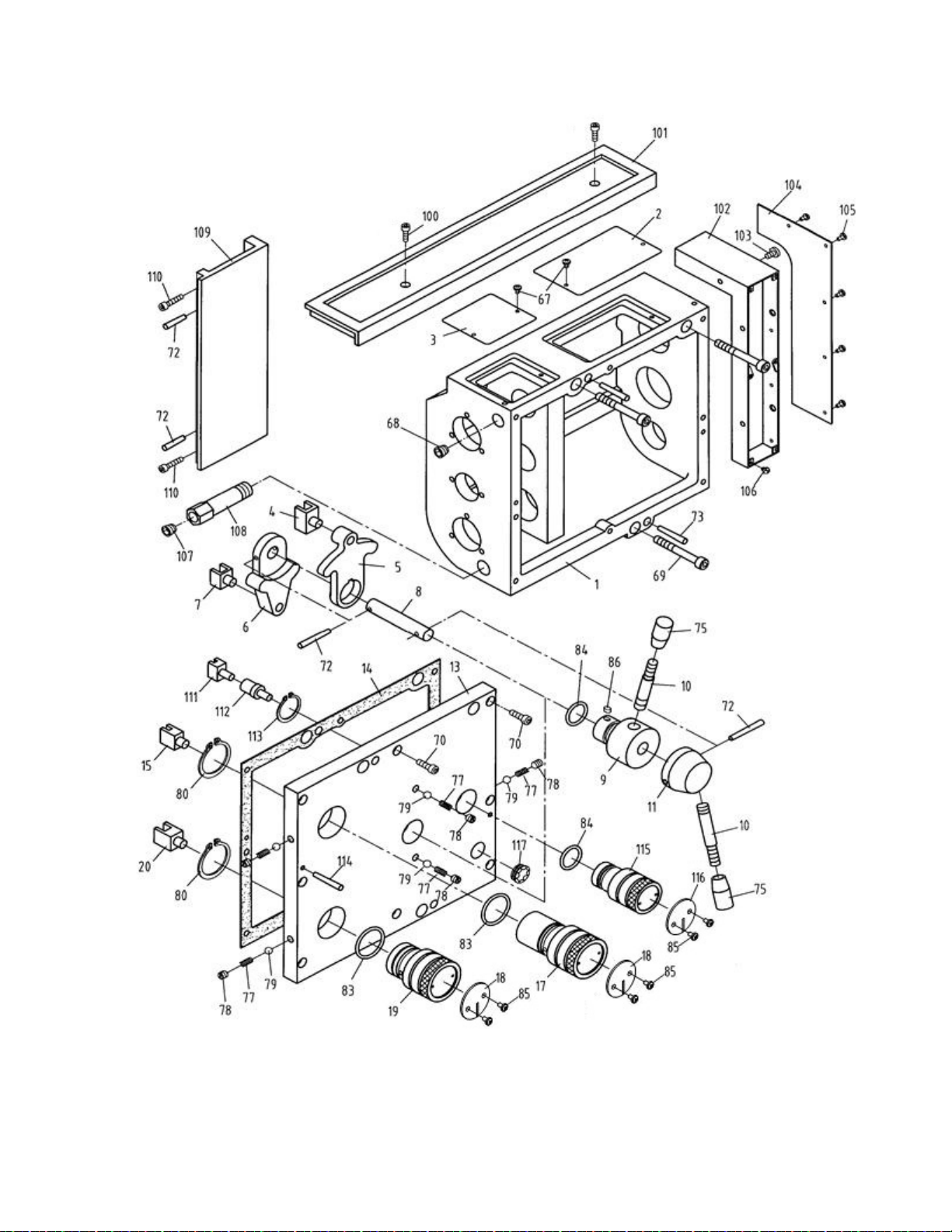
9.1 Gear Assembly I – Exploded View
23

9.2 Gear Assembly I – Parts List
24
Index Part
No No Description Size Qty
1
..............
05101AG ................... Casting ..................................................................... ......................................
1
2
..............
05715G ...................... Right cover ............................................................... .....................................
1
3
..............
05720G ...................... Left
cover
................................................................. ......................................
1
4
..............
32A5308 .................... Slipper ...................................................................... ......................................
1
5
..............
32A5111A .................. Lever ........................................................................ .....................................
1
6
..............
32A5108A .................. Lever ........................................................................ ......................................
1
7
..............
32A5307 .................... Slipper ...................................................................... ......................................
1
8
..............
32A5702 .................... Shaft ......................................................................... .....................................
1
9
..............
32A5109G ................. Handle Base............................................................. ......................................
1
10
............
32A5701G ................. Lever ........................................................................ ......................................
2
11
............
32A5110G ................. Handle Base............................................................. ......................................
1
13
............
GHB1340A-05106G .. Cover ....................................................................... ......................................
1
14
............
05504 ........................ Gasket ...................................................................... ......................................
1
15
............
32A5305 .................... Slipper ...................................................................... ......................................
1
17
............
32A5106G ................. Lever ........................................................................ .....................................
1
18
............
32A5302 .................... Plate(serial #16013258A and lower) ................... ......................................
2
................
C0632B05302 -2 ........ Plate(serial #16043259A and higher) .................. ......................................
2
19
............
32A5103G ................. Handle ...................................................................... ......................................
1
20
............
32A5306 .................... Slipper ...................................................................... ......................................
1
67
............
GHB1340A-G67 ........ Screw ....................................................................... M4x6 .............................
6
68
............
GHB1340A-G68 ........ Tapered Tap ............................................................ ZG3/8” ...........................
2
69
............
GHB1340A-G69 ........ Socket Head Cap Screw .......................................... M8x65 ...........................
3
70
............
TS-1503061 ............... Socket Head Cap Screw .......................................... M6x25 ...........................
8
72
............
GHB1340A-G72 ........ Pin ............................................................................ 5x30 ..............................
4
73
............
GHB1340A-G73 ........ Pin ............................................................................ 5x40 ..............................
2
75
............
07508 ........................ Knob ......................................................................... ......................................
2
77
............
GHB1340A-G77 ........ Spring ....................................................................... 0.8x5x25 ........................
5
78
............
TS-1524021 ............... Socket Set Screw ..................................................... M8x10 ...........................
5
79
............
SB-6 5MM ................. Steel Ball ..................................................................
6.5
....................................
5
80
............
GHB1340A-G80 ........ C-clip ........................................................................
40
..................................
2
83
............
GHB1340A-G83 ........ O-Ring ...................................................................... 40x3.1 ..............................
2
84
............
GHB1340A-G84 ........ O-Ring ...................................................................... 30x3.1 ..........................
2
85
...........
GHB1340A-G85 ........ Screw(serial #16013258A and lower) ................. M3x6 .............................
6
................
TS-1531012 ............... Screw(serial #16043259A and higher) ................ M3x6 .............................
6
86
............
GHB1340A-G86 ........ Key ........................................................................... 5x8 ................................
1
99 ............ GHB1340A-05503 ..... Rubber Mat (GHB-1340A only) (serial #16013258A and lower) ................ 1
................ GHB1440A-05503 ..... Rubber Mat (GHB-1440A only) (serial #16013258A and lower) ................ 1
................ BDB1340A-05503 ..... Rubber Mat (BDB-1340A only) (serial #1509B1613A and lower) .............. 1
100
..........
TS-1502041 ............... Socket Set Screw..................................................... M5x16 ...........................
2
101
..........
GHB1340A-05105G .. Top Cover (GHB-1340A only) .................................. ......................................
1
................
GHB1440A-05105G .. Top Cover (GHB-1440A only) .................................. ......................................
1
................
BDB1340A-05105G ... Top Cover (BDB-1340A
only)
.................................. ......................................
1
102
..........
05723G ...................... Cover........................................................................ ......................................
1
103
..........
GHB1340A-G103 ...... Screw ....................................................................... M4x8 .............................
3
104
..........
05722G ...................... Plate ......................................................................... ......................................
1
105
..........
GHB1340A-G105 ...... Screw ....................................................................... M3x5 .............................
5
106
..........
GHB1340A-G106 ...... Screw(serial #16013258A and lower) ................. M3x6 .............................
6
................
TS-1531012 ............... Screw(serial #16043259A and higher) ................ M3x6 .............................
6
107
..........
GHB1340A-G107 ...... Tapered Tap ............................................................ Z1/4” ..............................
1
108
..........
05724 ........................ Oil Drain Pipe ........................................................... ......................................
1
109
..........
05108G ...................... Extending Plate ........................................................ GHB-1340A/1440A .......
1
110
..........
TS-1502061 ............... Socket Head Cap Screw .......................................... M5x25 ...........................
2
111
..........
05305 ........................ Slipper ...................................................................... ......................................
1
112
..........
05721 ........................ Slipper Shaft ............................................................ ......................................
1
113
..........
GHB1340A-G113 ...... C-clip ........................................................................
30
..................................
1
114
..........
GHB1340A-G114 ...... Pin ............................................................................ 5x30 ..............................
2
115
..........
05107G ...................... Lever ........................................................................ ......................................
1

9.2 Gear Assembly I – Parts List
25
Index Part
No No Description Size Qty
116
..........
05304......................... Sign Disc(serial #16013258A and lower) ............ ......................................
1
................ GHB1340A-
05304-2 .. Sign Disc(serial #16043259A and higher) ........... ......................................
1
117
.........
GHB1340A-G117 ...... Oil Sight Glass(GHB-1340A,serial #10052363A and lower).
12mm ........ 1
................
GHB1340A-G117 ...... Oil Sight Glass(GHB-1440A,serial #08040097C and lower).
12mm ........ 1
................
GHB1340A-G117 ...... Oil Sight Glass(BDB-1340A,serial #1008B1083A and lower)
M27x1. 5 .... 1
................
GHB1340A-160M ...... Oil Sight Glass(GHB-1340A,serial #10102364A and higher)
M27x1.5 .... 1
................
GHB1340A-160M ...... Oil Sight Glass(GHB-1440A,serial #10110098C and higher)
M27x1.5 .... 1
................
GHB1340A-160M ...... Oil Sight Glass(BDB-1340A,serial #1010B1084A and higher)M27x1.5
.. 1
................
GHB1340A-05306 ..... Sign Plate (not shown) ............................................. GHB-1340A ...................
1
................
GHB1440A-05306 ..... Sign Plate (not shown) ............................................. GHB-1440A ...................
1
................
BDB1340A-05301...... Sign Plate (not shown) ............................................. BDB-1340A ...................
1
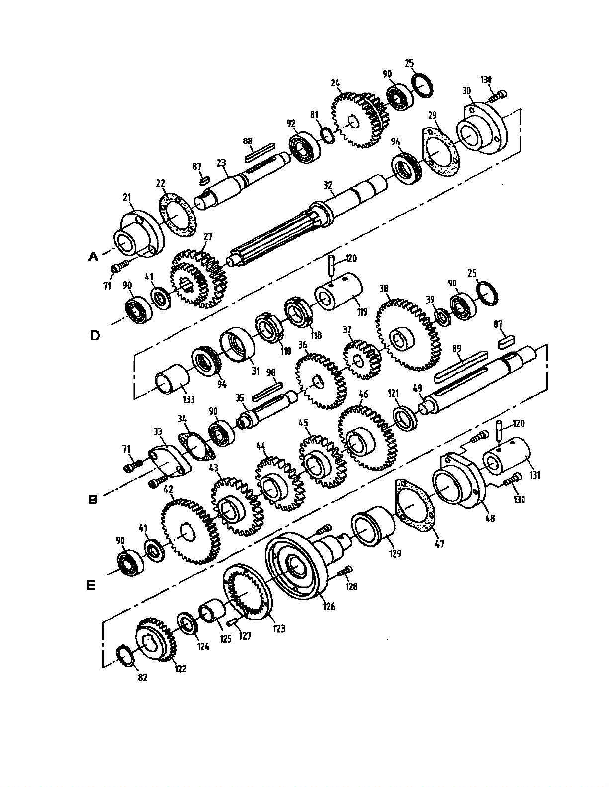
10.1 Gear Assembly II – Exploded View
26

10.2 Gear Assembly II – Parts List
27
Index Part
No No Description Size Qty
21
............
32A5113 .................... Cover ....................................................................... ......................................
1
22
............
32A5503 .................... Gasket ...................................................................... .....................................
1
23
............
32A5712 .................... Shaft ......................................................................... ......................................
1
24
............
32A5710A .................. Gear ......................................................................... 2.5m30T,20T .................
1
25
............
32A5719 .................... Washer ..................................................................... ......................................
2
27
............
05718 ........................ Gear ......................................................................... 2.25m,3.25m,2.5m24T ..
1
29
............
05502 ........................ Gasket ...................................................................... ......................................
1
30
............
05104 ........................
Bushing
.................................................................... ......................................
1
31
............
05714 ........................ Washer ..................................................................... ......................................
1
32
............
05716 ........................ Shaft ......................................................................... ......................................
1
33
............
32A5114 .................... End cover ................................................................. ......................................
1
34
............
32A5504 .................... Gasket ...................................................................... .....................................
1
35
............
32A5716 .................... Shaft ......................................................................... ......................................
1
36
............
32A5714A .................. Gear ......................................................................... 2.5m30T ........................
1
37
............
32A5715A .................. Gear ......................................................................... 2.5m20T ........................
1
38
............
32A5713A .................. Gear ......................................................................... 2.5m40T ........................
1
39
............
32A5708 .................... Washer ..................................................................... ......................................
2
41
............
05719 ........................ Washer ..................................................................... ......................................
2
42
............
05702 ........................ Gear ......................................................................... 2.25m40T ......................
1
43
............
05703 ........................ Gear ......................................................................... 3.25m24T ......................
1
44
............
05704 ........................ Gear ......................................................................... 3.25m22T ......................
1
45
............
05705 ........................ Gear ......................................................................... 3.25m21T ......................
1
46
............
05706 ........................ Gear ........................................................................ 2.5m36T ........................
1
47
............
05501 ........................ Gasket ...................................................................... ......................................
1
48
............
05103 ........................
Flange
...................................................................... .....................................
1
49
............
05717 ........................ Shaft ......................................................................... .....................................
1
71
............
TS-1504031 ............... Socket Head Cap Screw .......................................... M6x16 ...........................
5
81
............
GHB1340A-G81 ........ C-clip ........................................................................
20
..................................
1
82
............
GHB1340A-G82 ........ C-clip ........................................................................
25
..................................
1
87
............
GHB1340A-G87 ........ Key ........................................................................... 5x14 ..............................
1
88
............
GHB1340A-G88 ........ Key ........................................................................... 5x50 ..............................
1
89
............
GHB1340A-G89 ........ Key ........................................................................... 8x110 ............................
1
90
............
BB-6202 .................... Bearing .....................................................................
6202
..............................
5
92
............
BB-6004 .................... Bearing .....................................................................
6004
..............................
1
94
............
BB-51105 .................. Thrust Bearing ..........................................................
51105
............................
2
98
............
GHB1340A-G98 ........ Key ........................................................................... 5x55 ..............................
1
118
..........
GHB1340A-G118 ...... Round Nut ................................................................ M24x1.5 ........................
2
119
..........
05713 ........................ Connecting Sleeve ................................................... ......................................
1
120
..........
GHB1340A-G120 ...... Pin ............................................................................ 5x35 ..............................
4
121
..........
05707 ........................ Washer ..................................................................... ......................................
1
122
..........
05708 ........................ Gear ......................................................................... 2m30T ...........................
1
123
..........
05709 ........................ Inner Gear ................................................................ 2m30T ...........................
1
124
..........
05711 ........................ Washer ..................................................................... .....................................
1
125
..........
05302 ........................ Oil Light Bushing ...................................................... .....................................
1
126
..........
05710 ........................ XIB Shaft .................................................................. ......................................
1
127
..........
GHB1340A-G127 ...... Pin ............................................................................ 5n6x14...........................
2
128
..........
GHB1340A-G128 ...... Screw ....................................................................... M5x10 ...........................
2
129
..........
05301 ........................ Sliding Bearing ......................................................... ......................................
1
130
..........
TS-1503031 ............... Socket Head Cap Screw .......................................... M6x12 ...........................
6
131
..........
GHB1340A-05712 ..... Connecting Sleeve ................................................... ......................................
1
133
..........
05303 ........................ Bearing Housing....................................................... ......................................
1
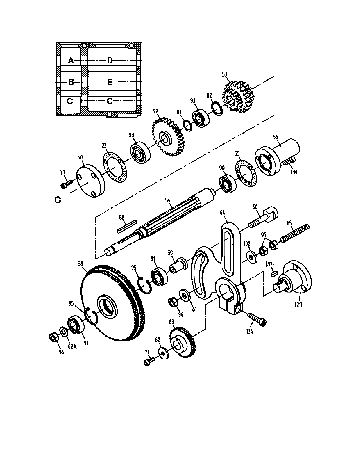
11.1 Gear Assembly III – Exploded View
28

11.2 Gear Assembly III – Parts List
29
Index Part
No No Description Size Qty
21
............
32A5113 ................... Cover ....................................................................... ......................................
1
22
............
32A5503 ................... Gasket ..................................................................... ......................................
1
50
............
32A5115 ................... End Cover................................................................ ......................................
1
52
............
32A5718A ................. Gear ........................................................................ 2.5m30T,15T .................
1
53
............
32A5721A ................. Gear ........................................................................ 2.25m,3.25m, 2.5m 18T ..
1
54
............
05701 ........................ Key shaft ................................................................. ......................................
1
55
............
05505 ........................ Gasket ..................................................................... ......................................
1
56
............
05102 ........................ Cover ....................................................................... ......................................
1
58
............
40A5736 ................... Gear ........................................................................ 1.25m120T,127T...........
1
59
............
40A5738 ................... Collar ....................................................................... ......................................
1
60
............
40A5739 ................... Screw....................................................................... ......................................
1
61
............
321719 ...................... Washer .................................................................... ......................................
1
62
............
40A5740 ................... Washer .................................................................... ......................................
2
62A .........
40A5740A ................. Washer .................................................................... ......................................
1
63
............
32A5726A ................. Gear ........................................................................ 1.25m48T......................
5
64
............
32A5119 ................... Gear Frame ............................................................. ......................................
1
65
............
321718 ...................... Screw rod................................................................. ......................................
1
71
............
TS-1504031 .............. Socket Head Cap Screw ......................................... M6x16 ...........................
4
81
............
GHB1340A-G81 ........ C-clip........................................................................
20
..................................
1
82
............
GHB1340A-G82 ........ C-clip........................................................................
25
..................................
1
87
............
GHB1340A-G87 ........ Key .......................................................................... 5x14 ..............................
1
88
............
GHB1340A-G88 ........ Key .......................................................................... 5x50 ..............................
1
90
............
BB-6202 .................... Bearing ....................................................................
6202
..............................
1
91
............
BB-6003Z .................. Bearing ....................................................................
6003Z
............................
2
92
............
BB-6004 .................... Bearing ....................................................................
6004
..............................
1
93
............
BB-6302 .................... Bearing ....................................................................
6302
..............................
1
95
............
GHB1340A-G95 ........ C-clip........................................................................
35
..................................
2
96
............
TS-1540071 .............. Hex
Nut
....................................................................
M10
...............................
2
97
............
TS-1540071 .............. Hex
Nut
....................................................................
M10
...............................
2
130
..........
TS-1503031 .............. Socket Head Cap Screw.......................................... M6x12 ...........................
3
132
..........
321719 ...................... Washer .................................................................... ......................................
1
134
..........
GHB1340A-G134 ...... Hex Socket Cap Screw ........................................... M8x30 ...........................
1
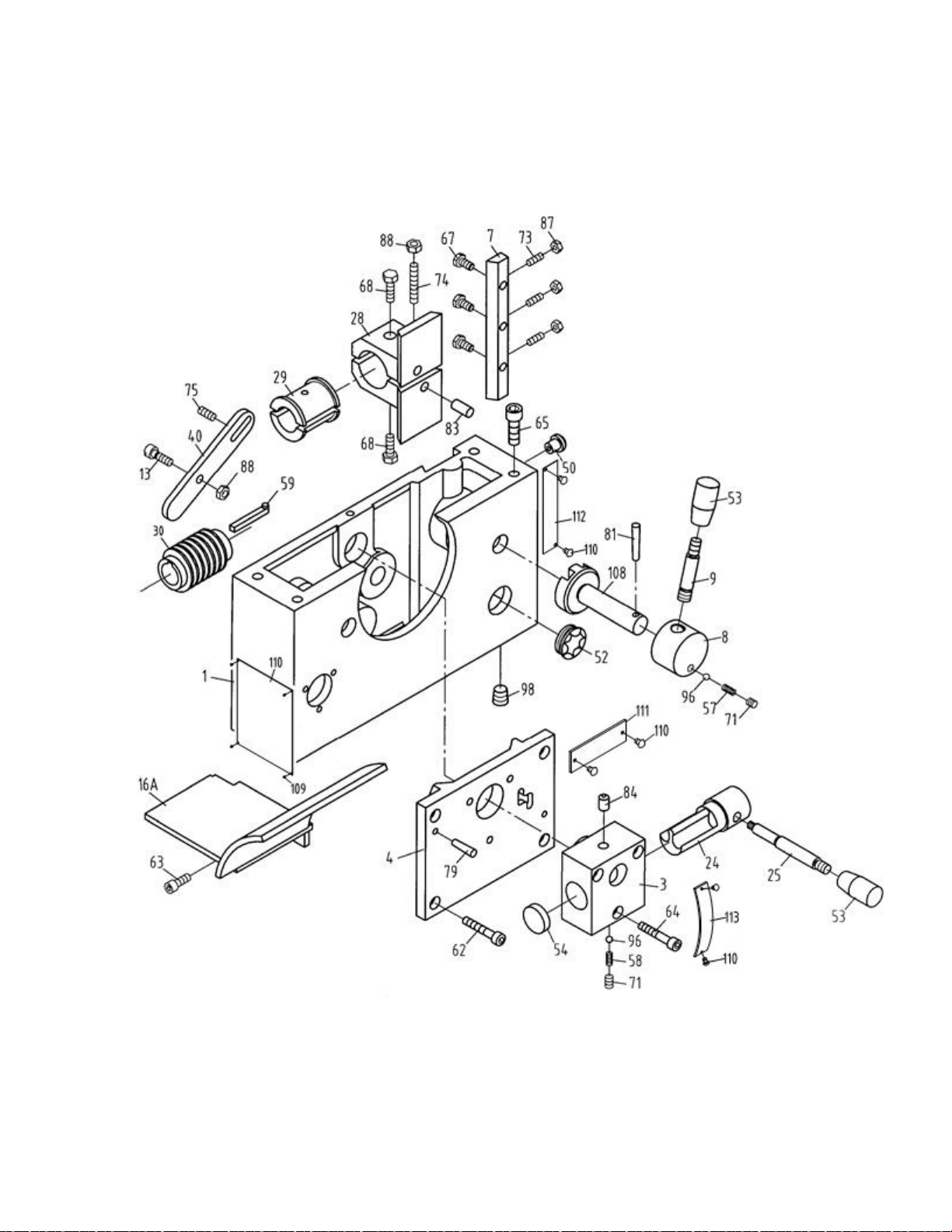
12.1 Apron Assembly I – Exploded View
30

12.2 Apron Assembly I – Parts List
31
Index Part
No No Description Size Qty
1
..............
GHB1340A-06101AG Casting ..................................................................... ......................................
1
3
..............
06103G ...................... Housing .................................................................... .....................................
1
4
..............
06104G ...................... Cover ....................................................................... ......................................
1
7
..............
06107 ........................ Gib ........................................................................... ......................................
1
8
..............
06208 ........................ Handle
Hub
.............................................................. ......................................
1
9
..............
06209 ........................ Handle ...................................................................... ......................................
1
13
............
06213 ........................ Gear Pin ................................................................... ......................................
1
16A ..........
06415G ...................... Bracket ..................................................................... ......................................
1
24
............
06222 ........................ Shift Lever ................................................................ ......................................
1
25
............
06223 ........................ Shift Handle.............................................................. ......................................
1
28
............
06126 ........................ Bracket ..................................................................... ......................................
1
29
............
06427 ........................ Half Nut .................................................................... ......................................
1
30
............
06228A ...................... Worm ....................................................................... 2m1T .............................
1
40
............
06238 ........................
Bar
........................................................................... ......................................
1
50
............
06548 ........................ Oil Filler Plug ............................................................ ......................................
1
52
...........
06551 ........................ Oil Sight Glass(GHB-1340A,serial #10052363A and lower)....................
1
................
06551 ........................ Oil Sight Glass(GHB-1440A,serial #08040097C and lower) ...................
1
................
06551 ........................ Oil Sight Glass(BDB-1340A,serial #1008B1083A and lower)..................
1
................
GHB1340A-160M…..Oil Sight Glass(GHB-1340A,serial #10102364A and higher)M27x1 5 ......
1
................
GHB1340A-160M…..Oil Sight Glass(GHB-1440A,serial #10100098C and higher)M27x1 5 ......
1
................
GHB1340A-160M…..Oil Sight Glass(BDB-1340A,serial #1010B1084A and higher)M27x1 5 ....
1
53
............
GHB1340-147 ........... Knob ......................................................................... M8x40 ...........................
2
54
............ Z06554
...................... Plug “A” .................................................................... ......................................
1
57
............
06257 ........................ Spring ....................................................................... ......................................
1
58
............
06258 ........................ Spring ....................................................................... ......................................
1
59
............
06260 ........................ Key ........................................................................... ......................................
1
62
............
TS-1503031 ............... Hex Socket Cap Screw ............................................ M6x12 ...........................
4
63
............
TS-1503041 ............... Hex Socket Cap Screw ............................................ M6x16 ...........................
1
64
............
TS-1503081 ............... Hex Socket Cap Screw ............................................ M6x35 ...........................
3
65
............
TS-1504061 ............... Hex Socket Cap Screw ............................................ M8x30 ...........................
4
67
............
GHB1340-A67 ........... Screw ....................................................................... M5x16 ...........................
3
68
............
TS-1523041 ............... Set Screw ................................................................. M6x12 ...........................
2
71
............
TS-1523011 ............... Set Screw ................................................................. M6x6 .............................
3
73
............
TS-1522051 ............... Set Screw ................................................................. M5x16 ...........................
3
74
............
GHB1340-A74 ........... Set Screw ................................................................. M6x35 ...........................
1
75
............
TS-1523031 ............... Set Screw ................................................................. M6x10 ...........................
1
79
............
GHB1340-A79 ........... Pin ............................................................................ 5x20 ..............................
2
81
............
GHB1340-A81 ........... Pin ............................................................................ 5x32 ..............................
1
83
............
GHB1340-A83 ........... Pin ............................................................................ 8n6x12 ..........................
2
84
............
GHB1340-A84 ........... Oiler .........................................................................
8
....................................
2
87
............
TS-1540031 ............... Hex
Nut
....................................................................
M5
.................................
3
88
............
TS-1540041 ............... Hex
Nut
....................................................................
M6
.................................
2
96
............
SB-5MM .................... Steel Ball ..................................................................
5
....................................
2
98
............
GHB1340A-A98 ......... Plug .......................................................................... Z1/4” ..............................
1
108
..........
06261 ........................ Half Nut Controlling Shaft ......................................... ......................................
1
109
..........
GHB1340A-6305A-1 . Plate(serial #16043259A and higher) .................. ......................................
1
110
..........
JHM610-151 .............. Rivet(serial #16043259A and higher)2x3mm ...... ....................................
10
111
..........
LM000204 ................. Feed Selector Label(serial #16043259A and higher) ................................
1
112
..........
LM000203 ................. Thread Engagement Label(serial #16043259A and higher) ......................
1
113
..........
C0632-01308-1 ......... Plate(serial #16043259A and higher) ................. ......................................
1
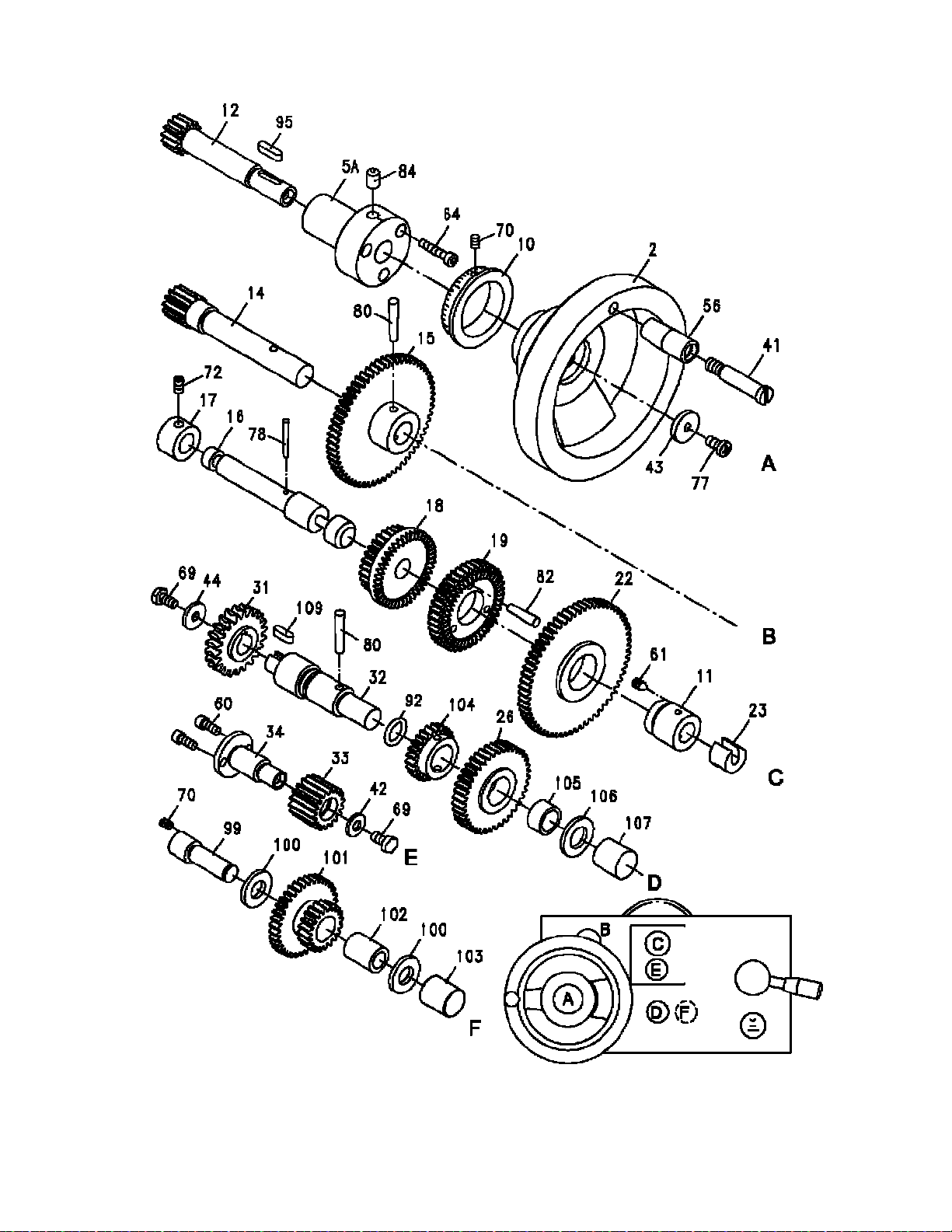
13.1 Apron Assembly II – Exploded View
32

13.2 Apron Assembly II – Parts List
33
Index Part
No No Description Size Qty
2
···········
06102G ···················· Handwheel ······································ ···········································
1
5A ·········
06105A ···················· Hub ················································ ···········································
1
10
··········
06510 ······················ Index Ring ······································· ···········································
1
11
·········· Z06111
···················· Cover ·············································· ···········································
1
12
··········
06212 ······················ Shaft··············································· 1.5m14T ·······························
1
14
··········
06214 ······················ Gear Shaft ······································· 1.5m13T ·······························
1
15
··········
06215 ······················ Gear ··············································· 1.5m60T ·······························
1
16
··········
06216 ······················ Shaft··············································· ···········································
1
17
··········
06417 ······················ Collar ·············································· ···········································
1
18
··········
06218 ······················ Gear ··············································· 1.5m30T ·······························
1
19
··········
06219 ······················ Gear ··············································· 1.5m40T ·······························
1
22
··········
06220 ······················ Gear ··············································· 1.5m46T ·······························
1
23
··········
06421 ······················ Shift Fork ········································· ···········································
1
26
··········
GHB1340A-06704 ······ Gear ··············································· 1.5m40T ·······························
1
31
··········
06429A ···················· Gear ··············································· 2m22T ··································
1
32
··········
GHB1340A-06714 ······ Shaft··············································· ···········································
1
33
··········
06231 ······················ Gear ··············································· 1.5m18T ·······························
1
34
··········
06232 ······················ Shaft··············································· ···········································
1
41
··········
06239G ···················· Screw ············································· ···········································
1
42
··········
TS-1550041 ·············· Washer ··········································· ···········································
1
43
·········· Z06241
···················· Washer ··········································· ···········································
1
44
··········
06242 ······················ Washer ··········································· ···········································
1
56
··········
06556G ···················· Handle ············································ ···········································
1
60
··········
TS-1502031 ·············· Hex Socket Cap Screw ······················ M5x12 ··································
2
61
··········
TS-1523011 ·············· Set Screw ········································ M6x6 ····································
1
64
··········
TS-1503061 ·············· Hex Socket Cap Screw ······················ M6x25 ··································
3
69
··········
TS-1503021 ·············· Screw ············································· M6x10 ··································
2
70
··········
TS-1522011 ·············· Set Screw ········································ M5x6 ····································
2
72
··········
TS-1523031 ·············· Set Screw ········································ M6x10 ··································
1
77
··········
GHB1340-A77 ··········· Screw ············································· M6x12 ··································
1
78
··········
GHB1340-A78 ··········· Pin ················································· 3x25 ·····································
1
80
··········
GHB1340-A80 ··········· Pin ················································· 5x30 ·····································
2
82
··········
GHB1340-A82 ··········· Pin ················································· 5x25 ·····································
3
84
··········
GHB1340-A84 ··········· Oiler ···············································
8
·········································
1
92
··········
GHB1340-A92 ··········· O-Ring ············································ 20x24 ···································
2
95
··········
GHB1340-A95 ··········· Key ················································ A5x
18
···································
1
99
··········
GHB1340A-06732 ······ Shaft··············································· ···········································
1
100
········
GHB1340A-06114 ······ Washer ··········································· ···········································
2
101
········
GHB1340A-06734 ······ Gear ··············································· 1.5m20T36T ··························
1
102
········
GHB1340A-06115 ······ Collar ·············································· ···········································
1
103
········
GHB1340A-A103 ······· Shaft Plug ········································ ···········································
1
104
········
GHB1340A-06731 ······ Gear ··············································· 1.5m24T ·······························
1
105
········
GHB1340A-06113 ······ Collar ·············································· ···········································
1
106
········
GHB1340A-06111 ······ Washer ··········································· ···········································
1
107
········
GHB1340A-06112 ······ Shaft Plug ········································ ···········································
1
109
········
GHB1340A-A109 ······· Key ················································ 5x12·····································
1
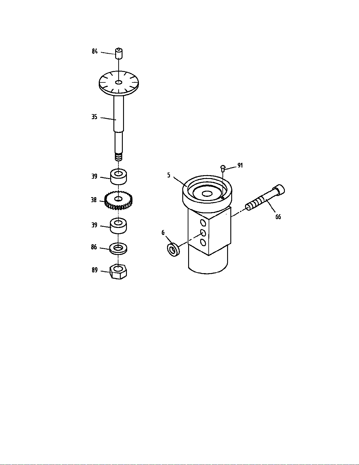
14.1 Apron Assembly III – Exploded View
34
14.2 Apron Assembly III – Parts List
Index Part
No No Description Size Qty
5
.............. Z06105G
................... Threading Dial Body ................................................ .....................................
1
6
..............
06206 ........................ Washer .................................................................... ......................................
1
35
............
06233 ........................ Threading Dial
Shaft
................................................ ......................................
1
38
............
06236 ........................ Gear ........................................................................ 1m32T...........................
1
39
............
06237 ........................ Spacer ..................................................................... ......................................
2
66
............
TS-1504101 .............. Hex Socket Cap Screw ........................................... M8x50 ...........................
1
84
............
GHB1340-A84........... Oiler .........................................................................
8
....................................
1
86
............
GHB1340-A86........... Lock Washer ...........................................................
M8
.................................
1
89
............
TS-1540061 .............. Hex
Nut
....................................................................
M8
.................................
1
91
............
GHB1340-A91........... Rivet......................................................................... 3x8 ................................
1
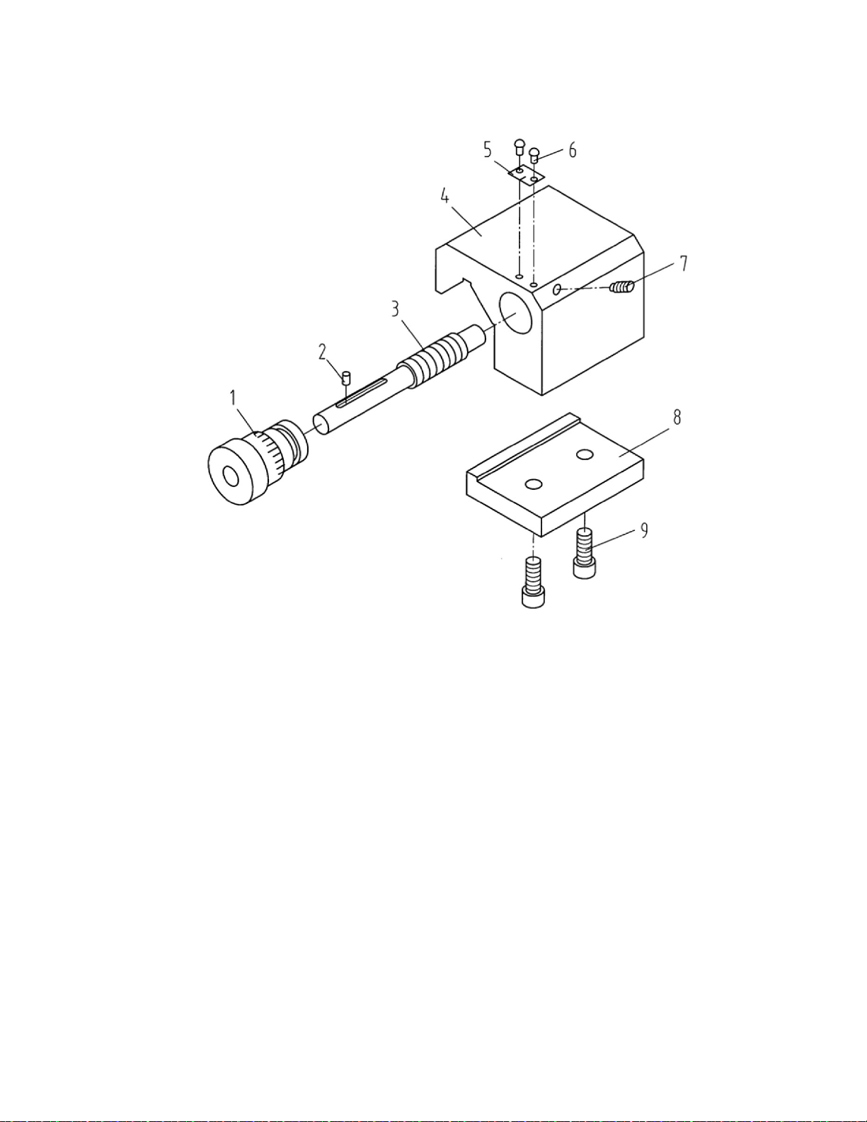
15.1 Micro Carriage Stop Assembly – Exploded View
35
15.2 Micro Carriage Stop Assembly – Parts List
Index Part
No No Description Size Qty
1
..............
GHB1340A-01707 ..... Dial ........................................................................... ......................................
1
2
..............
GHB1340A-MS02 ...... Pin ............................................................................ B3x
6
.................................
1
3
..............
GHB1340A-01716 .....
Axle
.......................................................................... ......................................
1
4
..............
GHB1340A-01107G .. Stop.......................................................................... ......................................
1
5
..............
ZX-03302 ................... Indicator
Plate
.......................................................... ......................................
1
6
.............. ZX-MS06
................... Pin ............................................................................ 3x8 ................................
2
7
..............
TS-1523031 ............... Socket Set Screw ..................................................... M6x10 ...........................
1
8
..............
GH1340A-01108 ....... Clamping Plate ......................................................... ......................................
1
9
..............
TS-1503051 ............... Hex Socket Cap Screw ............................................ M6x20 ...........................
2
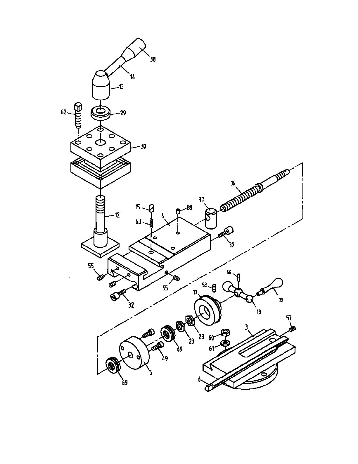
16.1 Top Slide, Tool Post, Saddle, and Cross Slide I – Exploded View
36

16.2 Top Slide, Tool Post, Saddle, and Cross Slide I – Parts List
37
Index Part
No No Description Size Qty
3
..............
07103 ........................ Swivel Slide (For GHB-1340A/BDB-1340A) ............ ......................................
1
................
C0636A-04103 .......... Swivel Slide (GHB-1440A Only) .............................. ......................................
1
4
..............
07104 ........................ Top Slide (For GHB-1340A/BDB-1340A) ................ ......................................
1
................
C0636A-04104 .......... Top Slide (GHB-1440A Only) .................................. ......................................
1
5
..............
07111 ........................ Collar ....................................................................... ......................................
1
6
..............
07117 ........................ Gib ........................................................................... ......................................
1
12
............
07205 ........................ Screw....................................................................... ......................................
1
13
............
07206 ........................ Handle Base ............................................................ ......................................
1
14
............
07207 ........................ Handle
Shaft
............................................................ ......................................
1
15
............
07209 ........................ Stop ......................................................................... ......................................
1
16
............
07210 ........................ Screw....................................................................... ......................................
1
17
............
07212 ........................ Index Ring................................................................ ......................................
1
18
............
07213G ..................... Ball Handle .............................................................. ......................................
1
19
............
07214G ..................... Handle ..................................................................... ......................................
1
23
............
07221 ........................ Nut ........................................................................... ......................................
2
29
............
07233 ........................ Washer .................................................................... ......................................
1
30
............
07234 ........................ Post Base ................................................................ ......................................
1
32
............
07237 ........................ Gib Adjusting Screw................................................. ......................................
2
37
............
07430 ........................ Nut ........................................................................... ......................................
1
38
............
07508 ........................ Knob ........................................................................ ......................................
1
49
............
TS-1503051 .............. Hex Socket Cap Screw............................................ M6x20 ...........................
2
53
............
TS-1523011 .............. Set Screw ................................................................ M6x6 .............................
1
55
............
TS-1523031 .............. Set Screw ................................................................ M6x10 ...........................
3
57
............
TS-1524011 .............. Set
Screw
................................................................ M8x8 .............................
1
60
............
TS-1540061 .............. Hex
Nut
.....................................................................
M8
.................................
2
61
............
TS-1550061 .............. Washer ....................................................................
8
....................................
2
62
............ GHB1340-62T
........... Screw....................................................................... M10x40 .........................
8
63
............ GHB1340-63T
........... Spring ...................................................................... 0.6x4x18 .......................
1
66
............ GHB1340-66T
........... Pin ........................................................................... 3x16 ..............................
1
69
............ GHB1340-69T
........... Ball Bear ing ............................................................. ......................................
2
88
............
GHB1340-88 ............. Oil Ball .....................................................................
6
....................................
3
................
GHB1340-TSA .......... Top Slide Assembly w/o Tool Post (For GHB-1340A/BDB-1340A) ................
1
................
GHB1440A-TSA ........ Top Slide Assembly w/o Tool Post (GHB-1440A Only) ..................................
1
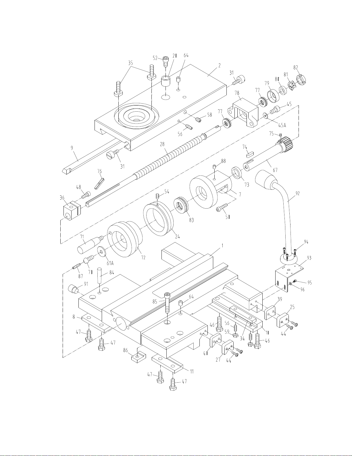
17.1 Top Slide, Tool Post, Saddle, and Cross Slide II – Exploded View
38

17.2 Top Slide, Tool Post, Saddle, and Cross Slide II – Parts List
39
Index Part
No No Description Size Qty
1 ............. 07101 ......................... Slide(GHB-1340A,serial #07061685A and lower) ...................................
1
(BDB-1340A,serial #0706B0764A and lower) ................................
1
................ GHB-1340A-04101A .. Sl ide(GHB-1340A,serial #07061686A and higher) ..................................
1
(BDB-1340A,serial #0707B0765A and higher) ...............................
1
(for GHB-1440A)
................ GHB-1340A-04101AG….Slide .................................................................... ......................................
1
2
..............
07102......................... Cross Slide ............................................................... ......................................
1
7
..............
07120N ...................... Bearing Housing ....................................................... ......................................
1
8
..............
07123......................... Strip .......................................................................... ......................................
1
9
..............
07131......................... Gib ........................................................................... ......................................
1
10
............
07132......................... Strip .......................................................................... ......................................
1
11
...........
07141 ........................ Front Strip(GHB-1340A,serial #07061685A and lower) ...........................
1
(BDB-1340A,serial #0706B0764A and lower) ........................
1
................
C0632-04111A .......... Front Strip(GHB-1340A,serial #07061686A and higher) .........................
1
(BDB-1340A,serial #0707B0765A and higher) ......................
1
(for GHB-1440A) ................................ ......................................
1
20
............
07216......................... Collar ........................................................................ ......................................
1
24
............
07222N ...................... Index Ring ................................................................ ......................................
1
25
............
07224......................... Plate ......................................................................... ......................................
2
27
............
07227......................... Plate ......................................................................... ......................................
2
28
............
07229N ...................... Screw ....................................................................... ......................................
1
31
............
07236......................... Gib Adjusting Screw ................................................. ......................................
2
34
............
07239......................... Gib
Strip
................................................................... ......................................
2
35
............
07240......................... T-Bolt........................................................................ ......................................
2
36
............
07415N ......................
Block
........................................................................ ......................................
1
39
............
07526......................... Wiper ........................................................................ ......................................
2
40
............
07528......................... Wiper ........................................................................ ......................................
2
44
............ GHB1340-44T
........... Screw ....................................................................... M4x12 ...........................
8
45
............
TS-1504051 ............... Hex Socket Cap Screw ............................................ M8x25 ...........................
2
45A ..........
TS-1551061 ............... Lock Washer ............................................................
M8
.................................
2
46
............ GHB1340-46T
........... Screw ....................................................................... M8x20 ...........................
3
47
............ GHB1340-47T
........... Screw ....................................................................... M8x20 ...........................
4
48
............
TS-1503041 ............... Hex Socket Cap Screw ............................................ M6x16 ...........................
1
50
............
TS-1503061 ............... Hex Socket Cap Screw ............................................ M6x25 ...........................
2
52
............
TS-1504031 ............... Hex Socket Cap Screw ............................................ M8x16 ...........................
1
54
............
TS-1523021 ............... Set Screw ................................................................. M6x8 .............................
1
56
............
TS-1523071 ............... Set Screw ................................................................. M6x25 ...........................
5
58
............
TS-1524021 ............... Set Screw ................................................................. M8x10 ...........................
1
59
............
TS-1540041 .............. Hex
Nut
....................................................................
M6
.................................
4
61A .......... GHB1340-65T
........... Washer ..................................................................... ......................................
1
64
............ GHB1340-64T
........... Oil Ball ......................................................................
8
....................................
5
67
............
07530......................... Gear Shaft ................................................................ ......................................
1
70
............
TS-1504041 ............... Screw ...................................................................... M8x20 ...........................
1
71
............
07531G ...................... H andle ...................................................................... ......................................
1
72
............
07532G ...................... C om pound
Handle
................................................... ......................................
1
73
............
07533......................... Spacer ...................................................................... ......................................
1
74
............
07534......................... Key ........................................................................... ......................................
1
75
............
07535......................... Set Screw ................................................................. M3x8 .............................
1
76
............
07536......................... Key ........................................................................... 5x5x30 ...........................
1
77
............
BB-8101 .................... Thrust Bearing ..........................................................
8101
..............................
2
78
............
07538......................... Bearing Housing ....................................................... ......................................
1
79
............
07539......................... Bearing Dust Cover .................................................. ......................................
1
80
............
07540......................... Washer ..................................................................... ......................................
1
81
............
07541......................... Star Washer ............................................................. ......................................
1
82
............
07542......................... Locking
Nut
.............................................................. ......................................
1
83
............
BB-8104 .................... Thrust Bearing ..........................................................
8104
..............................
1

17.2 Top Slide, Tool Post, Saddle, and Cross Slide II – Parts List
40
Index Part
No No Description Size Qty
84
............
GHB1340-84 ............. Taper
Pin
................................................................. 8x40 ..............................
2
85
............
GHB1340-85 ............. Hex Socket Cap Screw ............................................ M8x50 ...........................
1
86
............
GHB1340-86 ............. Locking
Washer
....................................................... ......................................
1
87
............
GHB1340-87 ............. Screw ....................................................................... M5x20 ...........................
1
88
............
GHB1340-88 ............. Oil Ball ......................................................................
6
....................................
1
91
............
GHB1340A-04789E ... S top Pin(GHB-1340A,serial #07061686A and higher) ............................
1
(BDB-1340A,serial #0707B0765A and higher) ..........................
1
(for GHB1440A) .................................... ...................................... 1
92 ........... GHB-EL ..................... Machine Lamp ......................................................... JC34A ........................... 1
93
............
GHB-1340A18710B ... Light Base ................................................................ ......................................
1
94
............
TS-1503051 ............... Hex Socket Cap Screw ............................................ M6x20 ...........................
3
95
............
TS-1503021 ............... Hex Socket Cap Screw ............................................ M6x10 ...........................
2
96 ............ TS-1550041 ............... Washer ..................................................................... 6mm .............................. 2
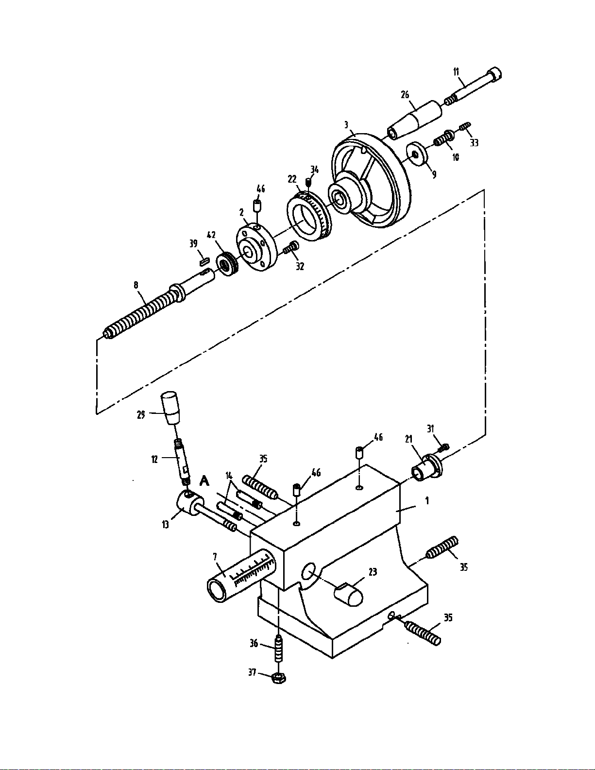
18.1 Tailstock Assembly I – Exploded View
41

18.2 Tailstock Assembly I – Parts List
42
Index Part
No No Description Size Qty
1
.............. Z08101G
................... Casting ..................................................................... ......................................
1
2
.............. Z08102G
................... Flange Cover............................................................ ......................................
1
3
..............
08103G ...................... Hand
Wheel
............................................................. ......................................
1
7
..............
08202 ........................ Quill .......................................................................... ......................................
1
8
.............. Z08203
...................... Screw ....................................................................... ......................................
1
9
..............
GHB1340-09TS ......... W asher ..................................................................... ......................................
1
10
............ Z08205
...................... Screw ....................................................................... M8x20 ...........................
1
11
............
08206G ...................... Screw ....................................................................... ......................................
1
12
............ Z08207
...................... Lever ........................................................................ .....................................
1
13
............
08208 ........................ Shaft ......................................................................... ......................................
1
14
............
08209 ........................ Screw ....................................................................... ......................................
2
21
............
08401 ........................ Nut ........................................................................... ......................................
1
22
............
08402 ........................ Index Ring ................................................................ ......................................
1
23
............
08403 ........................ Pivot
Block
............................................................... ......................................
1
26
............
08501G ...................... Handle ...................................................................... ......................................
1
29
............
GHB1340-147 ........... Knob......................................................................... M8x40 ...........................
1
31
............
TS-1501031 ............... Hex Socket Cap Screw ............................................ M4x10 ...........................
3
32
............
TS-1503041 ............... Hex Socket Cap Screw ............................................ M6x16 ...........................
4
33
............
TS-1522061 ............... Set Screw ................................................................. M5x20 ...........................
1
34
............
TS-1523031 ............... Set Screw ................................................................. M6x8 .............................
1
35
............
GHB1340-35TS ......... Set Screw ................................................................. M10x45 .........................
3
36
............
GHB1340-36TS ......... Screw ....................................................................... M8x35 ...........................
1
37
............
TS-1540061 ............... Hex
Nut
....................................................................
M8
.................................
1
39
............
GHB1340-39TS ......... Key ........................................................................... 4x15 ..............................
1
42
............
BB-51102 .................. Bearing .....................................................................
8102
..............................
1
46
............
GHB1340-43TS ......... Oil Ball ......................................................................
8
....................................
3
................ Z08201
...................... Live Center (not shown) ........................................... MT3 ...............................
1
................
8404 .......................... Arrow Plate (not shown) ........................................... ......................................
1
................
8405 .......................... Scale Plate (not shown) ........................................... ......................................
1
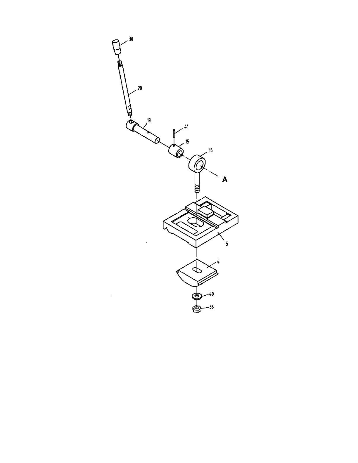
19.1 Tailstock Assembly II – Exploded View
43
19.2 Tailstock Assembly II – Parts List
Index Part
No No Description Size Qty
4
..............
08104 ........................ Clamp Plate ............................................................. ......................................
1
5
..............
08105G ..................... Base (For GHB-1340A/BDB-1340A) ....................... ......................................
1
................
C0636A-03104G ....... Base (For GHB-1440A) ........................................... ......................................
1
15
............
08211 ........................ Collar ....................................................................... ......................................
1
16
............
08212 ........................ Screw (For GHB-1340A/BDB-1340A) ..................... ......................................
1
................
C0636A-03707 .......... Screw (For GHB-1440A) ......................................... ......................................
1
19
............
08213 ........................ Shaft ........................................................................ ......................................
1
20
............
08214 ........................ Lever ....................................................................... ......................................
1
30
............
07508 ........................ Knob ........................................................................ ......................................
1
38
............
TS-1540081 .............. Hex
Nut
....................................................................
M12
...............................
1
40
............
TS-2360121 .............. Washer ....................................................................
12 mm
...........................
1
41
............
GHB1340-41TS......... Pin ........................................................................... 5x25 ..............................
1
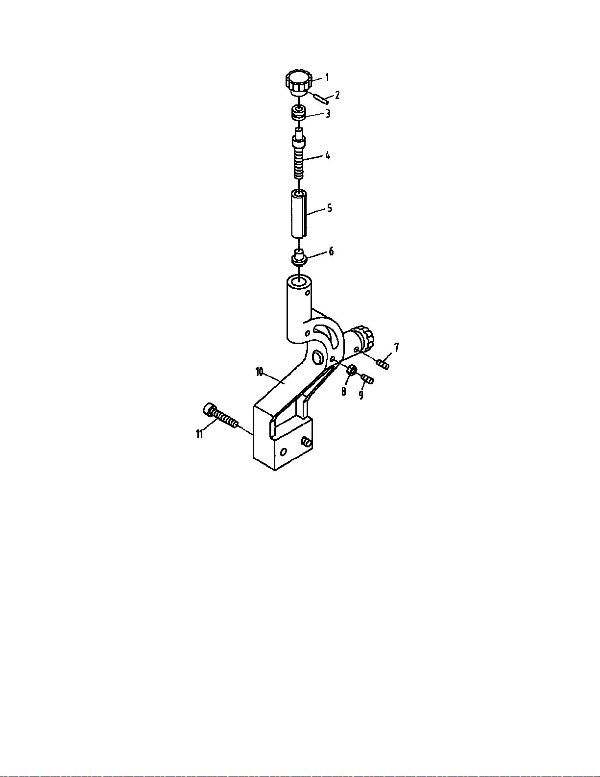
20.1 Follow Rest – Exploded View
44
20.2 Follow Rest – Parts List
Index Part
No No Description Size Qty
1
..............
GHB1340-1FR ........... Knob ......................................................................... ......................................
2
2
..............
GHB1340-2FR ........... Pin ............................................................................ 3x18 ..............................
2
3
..............
10208 ........................
Bushing
.................................................................... ......................................
2
4
..............
10204 ........................ Screw ....................................................................... ......................................
2
5
..............
10201 ........................
Sleeve
...................................................................... ......................................
2
6
..............
10401 ........................ Brass Finger ............................................................. ......................................
2
7
..............
TS-1523011 ............... Set Screw ................................................................. M6x8 .............................
2
8
..............
TS-1540041 ............... Nut ...........................................................................
M6
.................................
2
9
..............
TS-1523051 ............... Set Screw ................................................................. M6x16 ...........................
2
10
............
10104G ...................... Base Casting (For GHB-1340A/BDB-1340A) ........... ......................................
1
................
C0636A-10104G ....... Base Casting (For GHB-1440A) ............................... ......................................
1
11
............
TS-1504071 ............... Hex Socket Cap Screw ............................................ M8x35 ...........................
2
................
GHB1340-FRG .......... Follow Rest Complete (For GHB-1340A/BDB-1340A) ................................
1
................
GHB1440A-FRG ....... Follow Rest Complete (For GHB-1440A) ............. ......................................
1
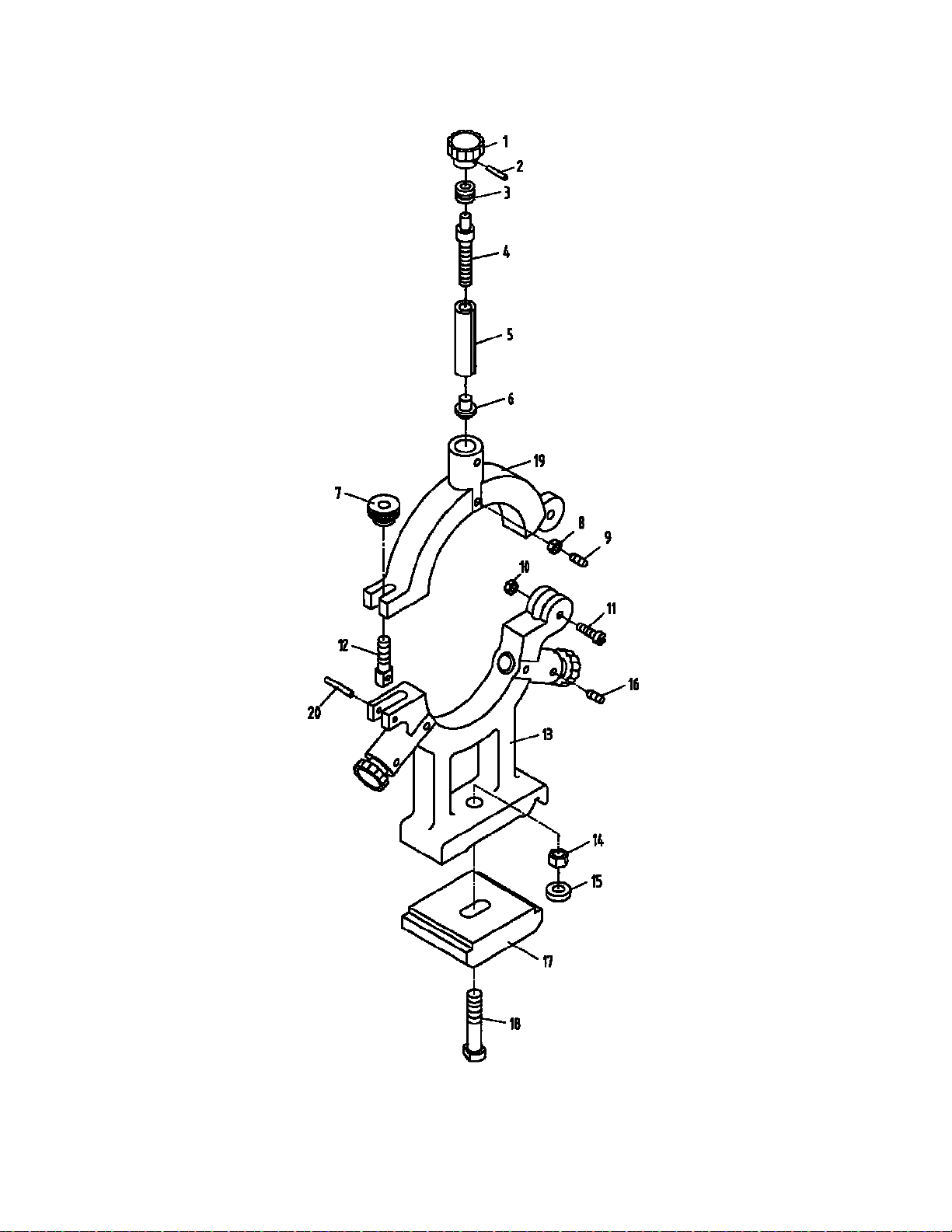
21.1 Steady Rest – Exploded View
45

21.2 Steady Rest – Parts List
46
Index Part
No No Description Size Qty
1
..............
GHB1340-1FR .......... Knob ........................................................................ ......................................
3
2
..............
GHB1340-2FR .......... Pin ........................................................................... 3x18 ..............................
3
3
..............
10203 ........................
Bushing
.................................................................... ......................................
3
4
..............
10204 ........................ Screw....................................................................... ......................................
3
5
..............
10201 ........................
Sleeve
...................................................................... ......................................
3
6
..............
10401 ........................ Brass Finger ............................................................ ......................................
3
7
..............
10205 ........................ Lock Knob................................................................ ......................................
1
8
..............
TS-1540041 .............. Nut ...........................................................................
M6
.................................
3
9
..............
TS-1523051 ............. Set Screw ............................................................... M6x16 ...........................
3
10
............
TS-1540041 .............. Nut ...........................................................................
M6
.................................
1
11
............
GHB1340-11SR ........ Bolt .......................................................................... M6x30 ...........................
1
12
............
10206 ........................ Pivot Bolt.................................................................. ......................................
1
13
............
10102G ..................... Base Casting (For GHB-1340A/BDB-1340A) .......... ......................................
1
................
C0636A-10101G ....... Base Casting (For GHB-1440A) .............................. ......................................
1
14
............
TS-1540081 .............. Nut ...........................................................................
M12
...............................
1
15
............
TS-1550081 .............. Flat Washer .............................................................
12mm
............................
1
16
............
TS-1523021 .............. Set Screw ............................................................... M6x8 .............................
3
17
............
10103 ........................ Clamp Rod............................................................... ......................................
1
18
............
TH1340-18SR ........... Clamp Screw ........................................................... ......................................
1
19
............
10101G ..................... Top Casting ............................................................. ......................................
1
20
............
GHB1340-20SR ........ Pin ........................................................................... 5x25 ..............................
1
................
GHB1340-SRG ......... Steady Rest Complete (For GHB-1340A/BDB-1340A) ..................................
1
................
GHB1440A-SRG ....... Steady Rest Complete (For GHB-1440A) ............... ......................................
1
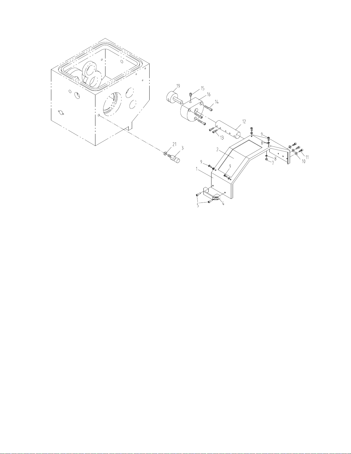
22.1 GHB-1340A/1440A Chuck Guard Assembly – Exploded View
47
22.2 GHB-1340A/1440A Chuck Guard Assembly – Parts List
Index Part
No No Description Size Qty
................
GHB-CGA ................. Chuck Guard Assembly(index #1 thru 21) .......... ...................................... 1
1 .............. GHB1340A-19701EG Protection Guard...................................................... ...................................... 1
2 ............ GHB1340A-19501E ... Protection Guard Visual Glass ................................. ...................................... 1
3 .............. ZX-19704E ................ Fixing Rod ............................................................... ...................................... 1
4 ............. SG-04 ........................ Handle(serial #16013258A and lower)HY32-1 ... ...................................... 1
................ A90 ............................ Handle(serial #16043259A and higher) .............. ...................................... 1
5 .............. TS-1503031 .............. Hex Socket Cap Screw ............................................ M6x12 ........................... 2
7 .............. TS-1540021 .............. Hex Thin Nut ............................................................ M4 ................................. 4
8 .............. TS-1550031 .............. Plain Washer ........................................................... 4 mm ............................. 8
9 .............. TS-1532042 .............. Cross Recessed Pan Head Screws ......................... M4x12 ........................... 4
10 ............ TS-1550031 .............. Plain Washer ........................................................... 6 mm ............................. 3
11 ............ TS-1534032 .............. Cross Recessed Pan Head Screws ......................... M6x10 ........................... 3
12 ............ GHB1340A-19703E ... Rest Bar .................................................................. ...................................... 1
13 ............ TS-1524021 .............. Hex Socket Set Screw ............................................ M8x10 ........................... 2
14 ............ TS-1503071 .............. Hex Socket Cap Screw ............................................ M6x30 ........................... 3
15 ............ TS-1524041 .............. Hex Socket Set Screw ............................................. M8x16 ........................... 1
16 ............ GHB1340A19704 ...... Switch Box ............................................................... ...................................... 1
19 ............ GHB1340A19702E .... Shaft ........................................................................ ...................................... 1
21
............
TS-1540061 .............. Hex
Nut
....................................................................
M8
.................................
1

23.0 Additional Parts (Not Shown)
48
Index Part
No No Description Size Qty
············
GHB 1340-FP ············· Face Plate ········································12”
D1-4
································
1
············
GHB1340-TBC··········· Tool Box Complete ·······································································
1
············
321449 ····················· Chuck ·············································6” 3Jaw ································
1
············
321430 ····················· Chuck ·············································8” 4Jaw ································
1
············
GHB1340A-CG1 ········ Change Gear ····································1.25m44T ·····························
1
············
GHB1340A-CG2 ········ Change Gear ····································1.25m48T ·····························
1
············
GHB1340A-CG3 ········ Change Gear ···································1.25m33T ·····························
1
············
GHB1340A-CG4 ········ Change Gear ···································1.25m46T ·····························
1
············
GHB1340A-CG5 ········ Change Gear ····································1.25m52T ·····························
1
24.0 Additional Electrical Components (Not Shown)
Index Part
No No Description Size Qty
············
BDB1340-QS1 ··········· Main Power Switch (BDB-1340A Only) ·············································
1
············
BDB1340-QS1-A ········ Faceplate f or P ower Switch (BDB-1340A Only) ··································
1
············
BDB1340-QS1-B ········ Knob for Power Switch (BDB-1340A Only) ········································
1
············
321320 ····················· Motor (2HP,1Ph,60HZ 230V only for GHB-1340A/1440A) ····················
1
············
GHB1340-MP ············ Motor Pulley ················································································
1
············
321321 ····················· Motor (2HP,1Ph,60HZ 230V only for BDB-1340A)·······························
1
············
BDB1340-MP ············ Motor Pulley ················································································
1
············
GHB1340-C ·············· Capacitor (same with BDB-1340A) ···················································
1
············ GHB1340-CC
············ Capacitor Cover (same with BDB-1340A) ··········································
1
············ GHB1340-CSF
·········· Centrifugal Switch Fixture (same with BDB-1340A) ·····························
1
············
GHB1340-CSR ·········· Centrifugal Switch
Rotor
································································
1
············
BDB1340-CSR ·········· Centrifugal Switch
Rotor
································································
1
············
GHB1340A-EBCG ······ Electrical Box Complete ·································································
1
············
BDB1340A-EBCG ······ Electrical Box Complete ·································································
1
············
GHB1340A-18701G···· Electrical Box (bare) ······································································
1
············
BDB1340A-18701G ···· Electrical Box (bare) ······································································
1
············
GHB1340-JB ············· Motor Junction
Box
···························· ··············································
1
············
BDB1340-JB ············· Motor Junction
Box
·······································································
1
············
GHB1340A-RSB ········ Rotary Switch Box ········································································
1
············
GHB1340A-SP··········· Electric Switch Plate (GHB-1340A/1440A Only) ··································
1
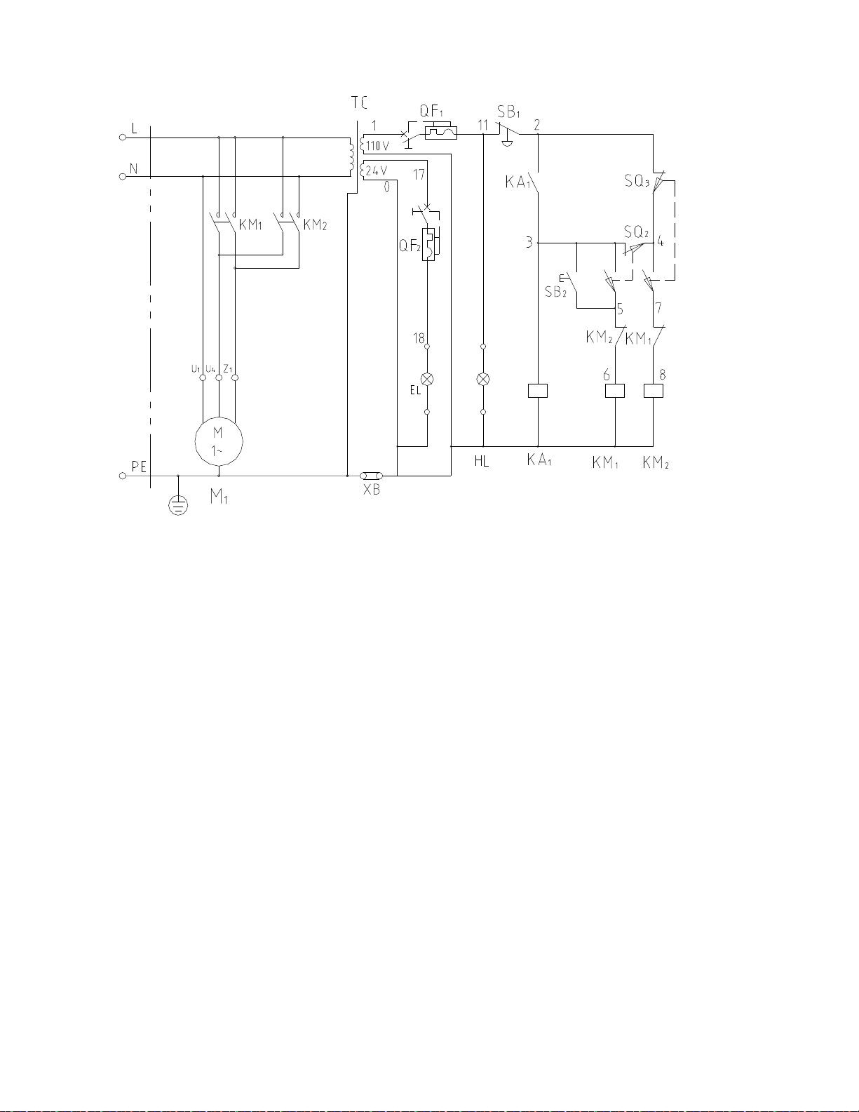
25.1 Electrical Schematic – GHB-1340A/1440A
49
25.2 Electrical Schematic Parts List – GHB-1340A/1440A
Index Part
No No Description Size Qty
1 ·········· GHB-SB1 ··············· Emergency Stop ···························· ZB2-BS54C ······················· 1
2 ·········· GHB-SB2 ··············· Jog Button ···································· XB2-EA131 ························ 1
3 ·········· GHB-HL ················· Power Indicator Light ······················ XB7-EVF3LC ····················· 1
4 ·········· GHB-KA1 ··············· Relay ·········································· HH52P ······························ 1
5 ·········· GHB-KM1 ··············· A.C.Contactor ······························· 3TB43······························· 1
6 ·········· GHB-KM2 ··············· A.C.Contactor ······························· 3TB43······························· 1
7 ·········· GHB-TC ················· Control Transformer ······················· JBK5-100VATH ·················· 1
8 ·········· GHB-SQ2 ··············· Stroke Switch ································ LXW5-11D1 ······················· 1
9 ·········· GHB-SQ3 ··············· Stroke Switch ································ LXW5-11D1 ······················· 1
10 ········· GHB-QF1 ··············· Breaker ······································· DZ47-63 ···························· 1
11 ········· GHB-QF2 ··············· Breaker ······································· DZ47-63 ···························· 1
12 ········· GHB-EL ················· Machine lamp ······························· JC34A ······························ 1
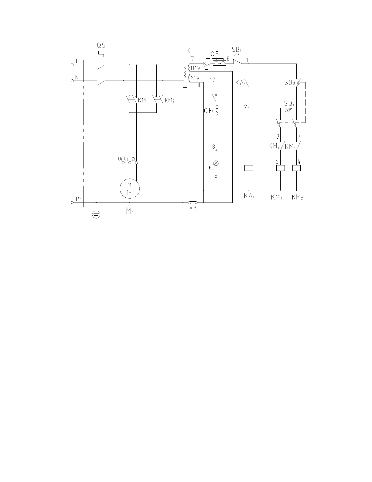
26.1 Electrical Schematic – BDB-1340A
50
26.2 Electrical Schematic Parts List – BDB-1340A
Index Part
No No Description Size Qty
1 ·········· BDB-SB1 ················ Emergency Stop ···························· ZB2-BS54C ······················· 1
2 ·········· BDB-KA1 ················ Relay ·········································· JZC3-40d ·························· 1
3 ·········· BDB-KM1 ··············· A.C.Contactor ······························· GSC1-D2501 ····················· 1
4 ·········· BDB -KM2 ·············· A.C.Contactor ······························· GSC1-D2501 ····················· 1
5 ·········· BDB-QS ················· Master switch ································ HZ5-20/4 ··························· 1
7 ·········· BDB-TC ················· Control Transformer ······················· JBK5-100VATH ·················· 1
8 ·········· BDB-SQ2 ··············· Stroke Switch ································ LXW5-11D1 ······················· 1
9 ·········· BDB-SQ3 ··············· Stroke Switch ································ LXW5-11D1 ······················· 1
10 ········· BDB-QF1················ Breaker ······································· DZ47-63 ···························· 1
11 ········· BDB-QF2················ Breaker ······································· DZ47-63 ···························· 1
12 ········· BDB-EL ·················· Machine lamp ······························· JC34A ······························ 1
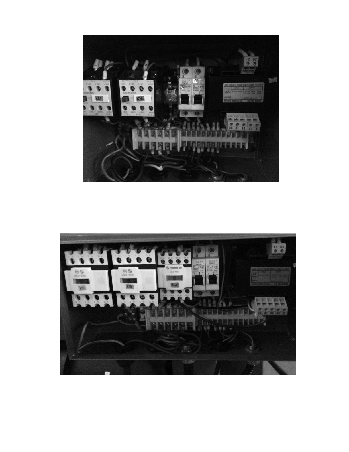
27.0 GHB-1340A/1440A Wiring Photo
51
28.0 BDB-1340A Wiring Photo