Loading ...
Loading ...
Loading ...
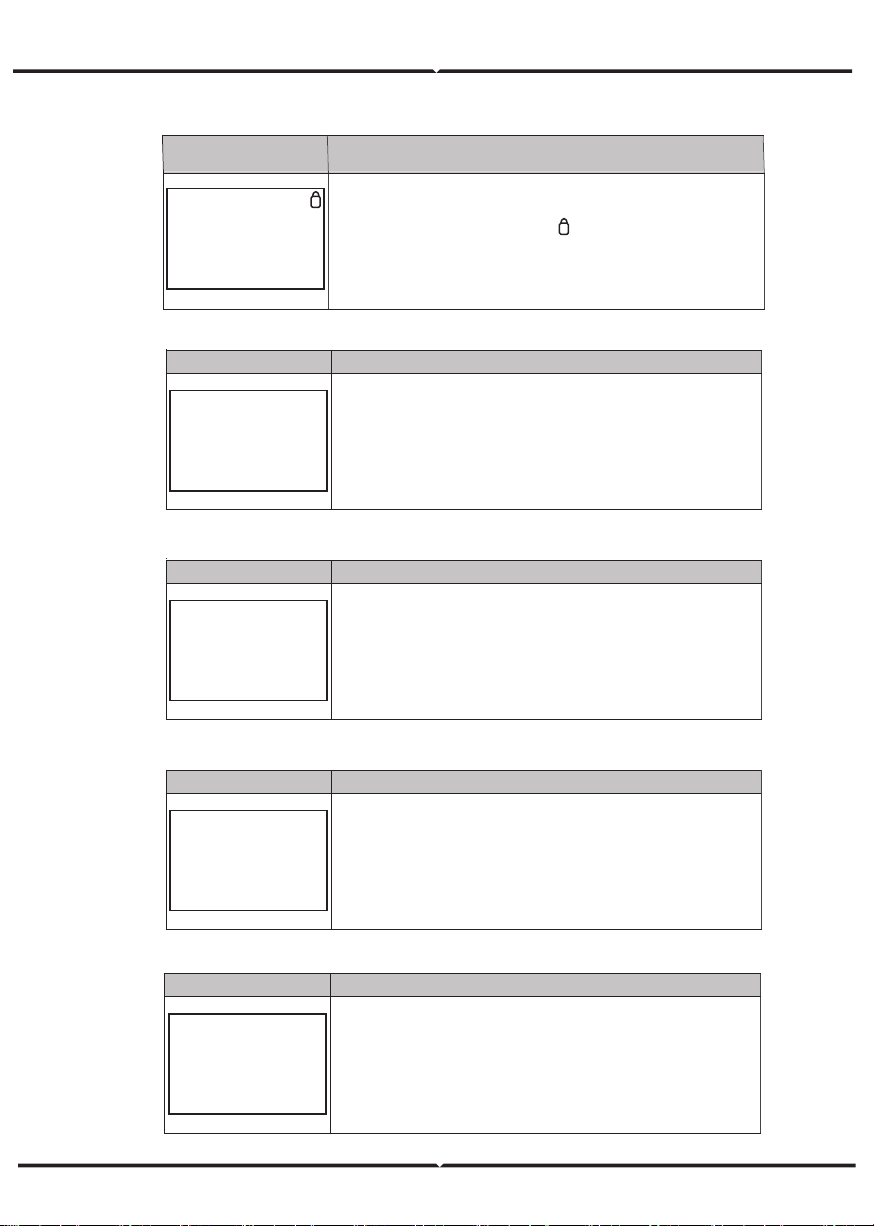
5.4.1 ERROR INFORMATION
Interface Description
ERROR NO.
02:BatDisconnect
27:BMS Comm.fail
Numbers represent error codes and text is error information.
Refer to Chapter 9 for specific contents.
NOTE: When there is a lock mark in the upper right corner of
the screen, you cannot turn the page, you need to press Enter to
unlock it first.
Interface Description
SYSTEM1
STATE: SELF CSM
GRID :
US-CA
PV I/P: PARALL
State: Setting of the whole machine working mode. Including:
SELF CONSUME, PEAK SHIFT and BAT PRIORITY.
Refer to Chapter 3.3 for specific contents.
Grid standard: Displays the grid standard actually set.
PV input mode: The display value is the setting value of PV
input type. Including: INDEPENDANT, PARALLEL, C V.
Interface Description
SYSTEM2
BMS Com: CAN
Anti Reve :
DISA
DOD: 80%
BMS Com: Battery Management System communication mode.
Including: CAN, RS485.
Anti Reve
: Displays Whether Inverter isn’t allowed to generate
electricity to the Grid. Including: DISABLE,ENABLE
DOD: Depth of battery discharge.
Interface Description
SYSTEM3
EPS ENABLE: ENAB
EPS ENABLE:
When the Grid and PV are powered off, Enable the
battery to supply power to the load, default option is enable.
Interface Description
PV1 INPUT
VOLT: 300V
CURR:
10.00A
POWER: 3000W
PV1 input real-time voltage, current and power.
LCD INTERFACE
5.4.2 SYSTEM SETTING
5.4.3 SYSTEM SETTING2
5.4.4 SYSTEM SETTING3
5.4.5 PV1 INPUT DISPLAY INTERFACE
Loading ...
Loading ...
Loading ...