

®
MODEL
917.257621 OWNER'SMANUAL
oAssembJy
oOperation
oCustomer Responsibilities
oService and Adjustments
o Repair Parts
CAUTION: Read and follow all safety rules and instructions before operating this equipment.
IIII III I ............................................ ................................................
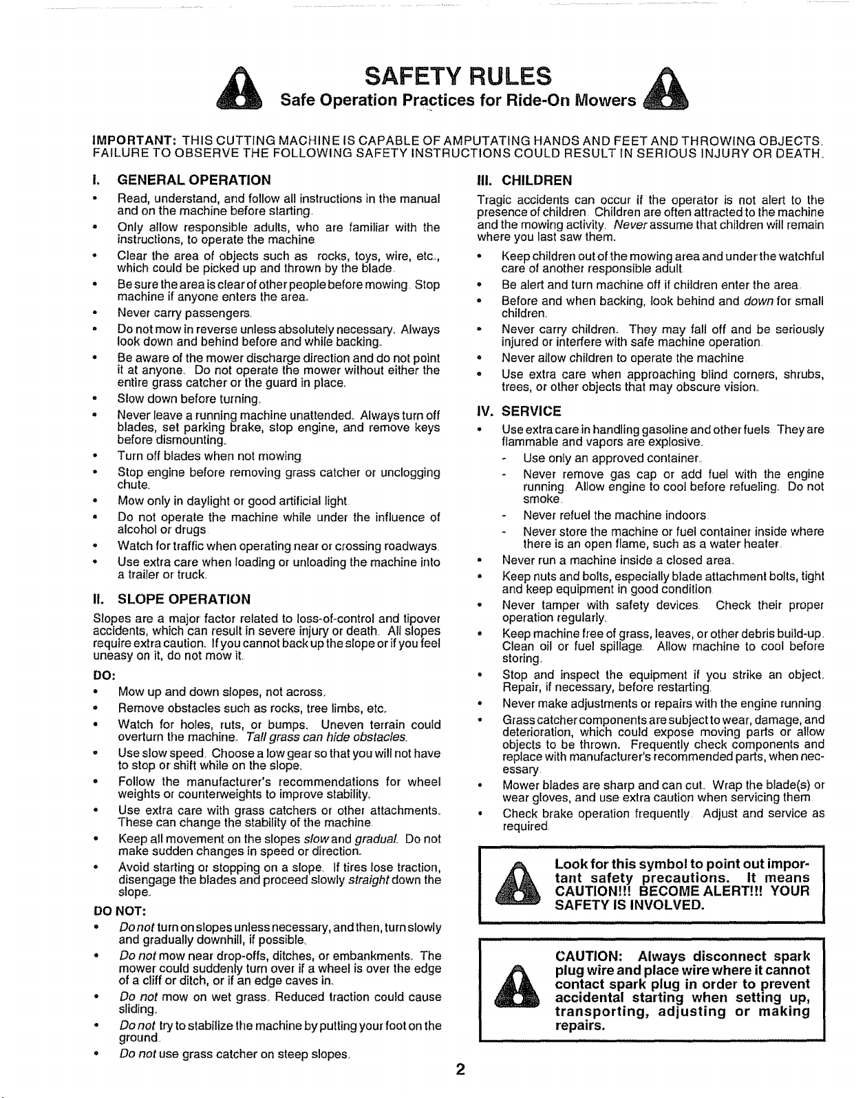
SAFETY RULES &
Safe Operation Practices for Ride-On Mowers
tMPORTANT: THIS CUTTING MACHINE IS CAPABLE OF AMPUTATING HANDS AND FEET AND THROWING OBJECTS
FAILURE TO OBSERVE THE FOLLOWING SAFETY INSTRUCTIONS COULD RESULT IN SERIOUS INJURY OR DEATH_
I. GENERAL OPERATION
• Read, understand, and follow all instructions in the manual
and on the machine before starting.
- Only allow responsible adults, who are familiar with the
instructions, to operate the machine
• Clear the area of objects such as rocks, toys, wire, etc.
which could be picked up and thrown by the blade.
• Be sure the area is clear of other people before mowing. Stop
machine if anyone enters the area.,
• Never carry passengers.
° Do not mow in reverse unless absolutely necessary., Always
look down and behind before and while backing..
° Be aware of the mower discharge direction and do not point
it at anyone. Do not operate the mower without either the
entire grass catcher or the guard in place..
o Slow down before turning.
° Never leave a running machine unattended_ Always turn off
blades, set parking brake, stop engine, and remove keys
before dismounting.
° Turn off blades when not mowing
° Stop engine before removing grass catcher or unclogging
chute°
° Mow only in daylight or' good artificial light
• Do not operate the machine whiie under the influence of
alcohol or drugs
. Watch for traffic when operating near or crossing roadways,
• Use extra care when loading or unloading the machine into
a trailer or truck..
11. SLOPE OPERATION
Slopes are a major factor related to loss-of-control and tipover
accidents, which can result in severe injury or death AU slopes
require extra caution, If you cannot back up the slope or if you feel
uneasy on it, do not mow it.
DO:
° Mow up and down slopes, not across.
,, Remove obstacles such as rocks, tree limbs, etc.
° Watch for holes, ruts, or bumps. Uneven terrain could
overturn the machine. Tall grass can hide obstacles.
', Use slow speed. Choose a low gear so that you will not have
to stop or shift while on the sloper
• Follow the manufacturer's recommendations for wheel
weights or counterweights to improve stability.
° Use extra care with grass catchers or other attachments°
These can change the stability of the machine.
• Keep atl movement on the slopes slowand gradual. Do not
make sudden changes in speed or direction.
o Avoid starting or stopping on a slope, if tires lose traction,
disengage the blades and proceed slowly straight down the
slope..
DO NOT:
• Do not turn on slopes unless necessary, and then, turnslowly
and gradually downhill, if possible..
• Do not mow near drop-offs, ditches, or embankments.. The
mower could suddenly turn over if a wheel is over the edge
of a cliff or ditch, or if an edge caves in.
• Do not mow on wet grass, Reduced traction could cause
sliding_
° Do not try to stabilize the machine by putting your foot on the
ground.
• Do not use grass catcher on steep slopes.
IlL CHILDREN
Tragic accidents can occur if the operator is not alert to the
presence of children Children are often attracted to the machine
and the mowing activity. Neverassume that children will remain
where you last saw them°
• Keep children out of the mowing area and under the watchful
care of another responsible adult
° Be alert and turn machine off if children enter the area.
° Before and when backing, took behind and down for small
children.
,, Never carry children.. They may fall off and be seriously
injured or' interfere with safe machine operation
• Never allow children to operate the machine
• Use extra care when approaching blind corners, shrubs,
trees, or other objects that may obscure vision..
IV. SERVICE
o Use extra care in handling gasoline and other fuels They are
flammable and vapors are explosive
Use only an approved container._
Never remove gas cap or add fuel with the engine
running Allow engine to coo] before refueling.. Do not
smoke.
Never refuel the machine indoors
Never store the machine or fuel container inside where
there is an open flame, such as a water heater.
= Never run a machine inside a closed area.
° Keep nuts and bolts, especially blade attachment bolts, tight
and keep equipment in good condition
° Never tamper with safety devices. Check their proper
operation regularly.
• Keep machine free of grass, leaves, or' other debris build-up,
Clean oil or fuel spillage. Allow machine to cool before
storing,
° Stop and inspect the equipment if you strike an object
Repair, if necessary, before restarting
• Never make adjustments or repairs with the engine running
• Grass catcher components are subject to wear, damage, and
deterioration, which could expose moving parts or allow
objects to be thrown. Frequently check components and
replace with manufacturer's recommended parts, when nec-
essary
° Mower blades are sharp and can cut.. Wrap the blade(s) or
wear gloves, and use extra caution when servicing them
• Check brake operation frequently Adjust and service as
required.
!
Look for this symbolto point out impor- I
tant safety precautions. It means
!
CAUTIONH! BECOME ALERT!!! YOUR
SAFETY IS INVOLVED.
CAUTION: Always disconnect spark
plug wire and place wire where it cannot
contact spark plug in order to prevent
accidental starting when setting up,
transporting, adjusting or making
repairs.
2

CONGRATULATIONS on your purchase of a Sears
Tractor° It has been designed, engineered and manufac-
tured to give you the best possible dependabitity and
performance.
Should you experience any problem you cannot easily
remedy, please contact your nearest Sears Authorized
Service CentedDepartmenL We have competent, well-
trained technicians and the proper tools to service or repair
this tractor.
Please read and retain this manual.. The instructions will
enable you to assemble and maintain you rtractor properly.
Always observe the "SAFETY RULES",.
MODEL
NUMBER
SERIAL
NUMBER
917.257621
DATE OF PURCHASE
THE MODEL AND SERIAL NUMBERS WILL BE FOUND
ON A PLATE UNDER THE SEAT..
YOU SHOULD RECORD BOTH SERIAL NUMBER AND
DATE OF PURCHASE AND KEEP IN A SAFE PLACE
FOR FUTURE REFERENCE..
MAINTENANCE AGREEMENT
A Sears Maintenance Agreement is available on this prod-
ucL Contact your nearest Sears store for details,,
CUSTOMER RESPONSIBILmES
• Read and observe the safety rules°
- Foltow a regularschedule in maintaining, caring for and
using your tractor,
• Follow the instructions under "Customer Responsibili-
ties" and "Storage" sections of this owner's manual
PRODUCT SPECiFiCATiONS
HORSEPOWER: 12..5
GASOLINE CAPACITY 5 QUARTS
AND TYPE: UNLEADED REGULAR
OIL TYPE (API-SF/SG): SAE 30 (above 32°F)
SAE 5W-30 (below 32°F)
OIL CAPACITY: 3 0 PINTS
SPARK PLUG: CHAMPION RJ19LM
(GAP: 025") STD 361458
VALVE CLEARANCE: INTAKE: 005" - ,007"
EXHAUST: ..009"- 0t1"
GROUND SPEED (MPH): FORWARD:
1st 1.02
2nd 210
3rd 3.t4
4th 4.00
5th 5.12
REVERSE: t58
TIRE PRESSURE: FRONT: t4 PSi
REAR: t0 PS1
CHARGING SYSTEM: 3 AMPS BATTERY
5 AMPS HEADLIGHTS
BLADE BOLT TORQUE: 30-35 FT LBS,
WARNING: This tractor is equipped with an internal
combustion engine and should not be used on or near any
unimproved forest-covered, brush-covered or grass-cov-
ered land unless the engine's exhaust system is equipped
with a spark arrester meeting applicable local or state laws
(if any)_ If a spark arrester is used, it should be maintained
in effective working order by the operator.
In the state of California the above is required by law
(Section 4442 of the California Public Resources Code).
Other states may have similar laws, Federal laws apply on
federal lands A spark arrester for the muffler is available
through your nearest Sears Authorized Service Center/
Department (See REPAIR PARTS section of this manual).
LIMITED TWO YEAR WARRANTY ON ELECTRIC START RiDiNG EQUIPMENT
For two (2) years from the date of purchase, if this riding equipment is maintained, lubricated and tuned up according to the
instructions in the owner's manual, Sears will repair or replace, free of charge, any parts found to be defective in material or
workmanship.
This Warranty does not cover:
° Expendable items which become worn during normal use, such as blades, spark ptugs, air cleaners and belts,,
• Tire replacement or repair caused by punctures from outside objects, such as nails, thorns_ stumps, or glass
° Repairs necessary because of operator abuse, negligence, improper storage or accident or:the failure to maintain the
equipment according to the instructions contained in the owner's manual,
o Riding equipment used for commercial or rental purposes
LiMiTED 90 DAY WARRANTY ON BATTERY
For ninety (90) days from date of purchase, if any battery included with this riding equipment proves defective in material or
workmanship and our testing determines the battery will not hold a charge, Sears will replace the battery at no charge..
WARRANTY SERVICE IS AVAILABLE BY RETURNING THE RIDING EQUIPMENT TO THE NEAREST SEARS SERVICE
CENTER/DEPARTMENT IN THE TRACTORED STATES,
This Warranty gives you specific legal rights, and you may also have other rightswhich may vary from state to state.
SEARS, ROEBUCK AND CO., D/817 WA, HOFFMAN ESTATES, ILLINOIS 60179
3
TABLE OF CONTENTS
SAFETY RULES ............................................................ 2
PRODUCT SPECIFICATIONS ...................................... 3
CUSTOMER RESPONSIBILITIES ..................... 3, 14-18
WARRANTY .................................................................. 3
TRACTOR ACCESSORIES .......................................... 5
ASSEMBLY ............................................................... 7-9
OPERATION .......................................................... 10-13
MAINTENANCE SCHEDULE ..................................... 14
SERVICE AND ADJUSTMENTS ........................... 19-24
STORAGE ................................................................... 25
TROUBLESHOOTING ........................................... 26-27
REPAIR PARTS - TRACTOR ................................ 30-47
REPAIR PARTS - ENGINE .................................... 48-53
PARTS ORDERING/SERVICE ............... BACK COVER
INDEX
A
Accessories .............................................. 5
Adjustments:
Brake .................................................. 21
Carburetor. ........................................ 24
Mower
Front-To-Back ............................ 20
Side-To-Side ............................... 20
Throttle Control Cable ................... 23
Air Filter', Engine .................................... 17
Air Screen, Engine ....................................17
Assembly ......................................................7*9
B
Battery:
Charging ............................................ 8
Cleaning .......................................... 16
Installation .............................................9
Levels ..............................................8,16
Preparation ...............................................8
Starting with Weak Battery ........... 22
Storage ............................................ 25
Terminals ...........................................16
Belt:
Motion Drive
Remova!/Replacement ...............21
Mower Blade(s)
Removal/Replacement ............ 21
Blade:
Sharpening .........................................15
Replacement .......................................15
Brake Adjustment ................................... 21
C
Carburetor Adjustment .............................24
Controls, Tractor ..................................... 10
Customer Responsibilities .................15-18
Engine:
Air Filter ......................................... 17
Air Screen, Engine ..................... 17
Cooling Fins, Engine .................. 17
Engine Oil ..................................... t 6
Fuel Filter .......................................18
Spark Plug(s) ....................................18
Tractor:
Battery ...................................................16
Blade ...............................................15
Lubrication Chart ...........................14
Maintenance Schedule .............. 14
Tire Care ..................................8,15,22
Transaxfe ...................................... 16
Culling Height, Mower ........................... 11
E
Electrical:
Interlocks and Relays ............... 23
Schematic ...........................................29
Wiring Diagram ....................................30
Engine:
Air Filter. ........................................... 17
Air' Screen ...........................................17
Cooling Fins, Engine ....................... 17
Oil Change .........................................16
Oil Level ............................................!2,16
Oil Type ................................................16
Preparation ..................................... 12
Repair Parts .................................44-48
Starting ............................................ 13
Storage ...............................................25
F
Filler:
Air Filter ........................................ 17
Fuel
....................................................
18
Fuel:
Type ........................................... 12
Storage ....................................... 25
Fuse ........................................................ 23
H
Hood Removal/Installation ..................... 23
L
Leveling Mower Deck ................................20
Lubrication:
Chart ...................................................14
M
Maintenance Schedule ...........................14
Mower:
Adjustment, Front4o-Back .............20
Adjustment, Side-to-Side ...............20
Blade Sharpening ..............................I5
Blade Replacement ..........................15
Cutting Height ....................................11
Installation ...................................... 19
Operation ......................................... 12
Removal .............................................19
Mowing Tips ............................................. 13
Muffler .........................................................18
Spark Arrester ..................................3,40
Oil:
O
Cold Weather Conditions ......... 12,16
Engine .................................................16
Storage ....................................................25
Operation ........................................... 10-13
Operating Mower. .........................................12
Options:
Accessories ..................................... 5
Spark Arrester, ............................ 3,40
P
Parking Brake .........................................10-11
Parts Bag ........................................................6
Parts, Replacement/Repair. ............ 28-43
Product Specifications .............................. 3
R
Repair Parts ....................................... 30-47
S
Safety Rules ................................................ 2
Seat ....................................................... 8
Service and Adjustments ................. 19-24
Carburetor ............................................24
Fuse .....................................................23
Hood Removal/Installation .............23
Motion Drive Belt
Removal/Replacement ..............21
Mower Belt(s)
RemovaVReplacement ............ 21
Mower Adjustment
Front-to-Back ............................ 20
Side-to.Side .............................. 20
Mower Removal ........................... 19
Tire Care .............................. 8,15,22
Slope Guide Sheet ............................... 51
Spark Plug(s) ........................................... 18
Specifications ......................................... 3
Starting the Engine ............................12-t3
Steering Wheel ........................................7,22
Stopping the Tractor. ............................... 11
Storage ...................................................... 25
T
Throttle Control Cable Adjustment ....... 24
Tires ........................................... 8,t5,22
Trouble Shooting Chart .......................26-27
Transaxle ...................................................16
W
Warranty .................................................. 3
Wiring Diagram ..................................... 30
Wiring Schematic ................................... 29
4
ruESAND ATTACH INT$
.......... + i,, i ,i,i ,,it,l, ....................................
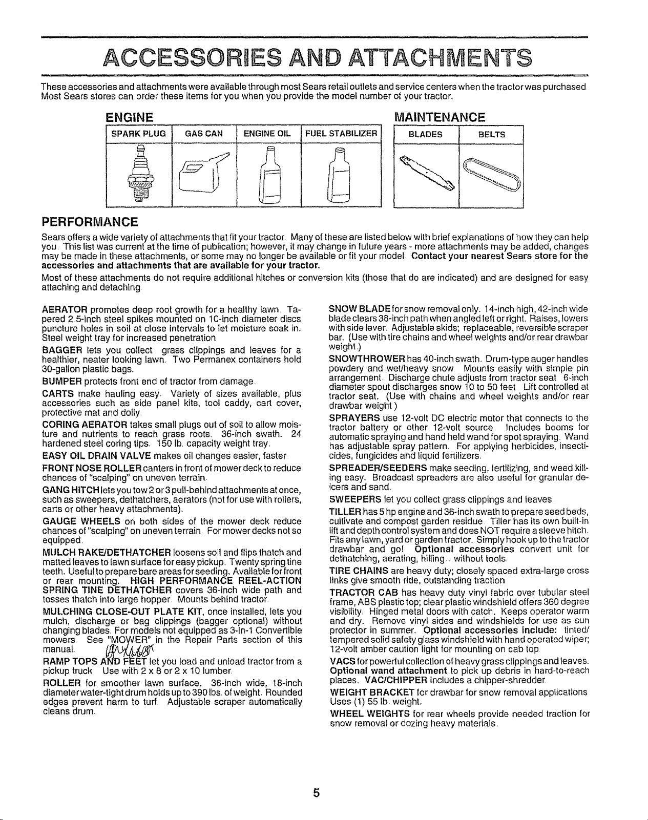
These accessories and attachments were available through most Sears retail outlets and service centers when the tractor was purchased
Most Sears stores can order these items for you when you provide the model number of your tractor.,
ENGINE
SPARK PLUG
+
GAS CAN ENGINE OIL FUEL STABILIZER
MAINTENANCE
BLADES BELTS
PERFORMANCE
Sears offers a wide variety of attachments that fit your tractor Many of these are listed below with brief explanations of how they can help
you This list was current at the time of publication; however, it may change in future years - more attachments may be added, changes
may be made in these attachments, or some may no longer be available or fit your model. Contact your nearest Sears store for the
accessories and attachments that are available for your tractor.
Most of these attachments do not require additional hitches or conversion kits (those that do are indicated) and are designed for easy
attaching and detaching.
AERATOR promotes deep root growth for a healthy fawn Ta-
pered 2 5+inch steel spikes mounted on 10-inch diameter discs
puncture holes in soil at close intervals to let moisture soak in+
Steel weight tray for increased penetration
BAGGER {ets you collect grass clippings and leaves for a
healthier, nearer looking lawn, Two Permanex containers hold
30+gallon plastic bags,
BUMPER protects front end of tractor from damage,
CARTS make hauling easy. Variety of sizes available, plus
accessories such as side panel kits, tool caddy, cart cover,
protective mat and dolly.
CORING AERATOR takes small plugs out of soil to allow mois-
ture and nutrients to reach grass roots. 36-inch swath.. 24
hardened steel coring tips, 150 lb. capacity weight tray.
EASY OIL DRAIN VALVE makes oil changes easier, faster
FRONT NOSE ROLLER canters in front of mower deck to reduce
chances of "scalping" on uneven terrain.
GANG HITCH lets you tow 2 or 3 putFbehind attachments at once,
such as sweepers, dethatchers, aerators (not for use with rollers,
carts or other heavy attachments).
GAUGE WHEELS on both sides of the mower deck reduce
chances of "scalping" on uneven terrain. For mower decks not so
equipped,
MULCH RAKE!DETHATCHER loosens soil and flips thatch and
matted leaves to lawn surface for easy pickup Twenty spring tine
teeth° Useful to prepare bare areasforseeding. Avaiiabieforfront
or rear mounting, HIGH PERFORMANCE REEL-ACTION
SPRING TINE DETHATCHER covers 36-inch wide path and
tosses thatch into large hopper Mounts behind tractor,
MULCHING CLOSE-OUT PLATE KIT, once installed, lets you
mulch, discharge or bag clippings (bagger optional) without
changing blades. For models not equipped as 3-in-1 Convertible
mowers. See "MOWER" _in the Repair Parts section of this
manual.. _L_._
RAMP TOPS AN'D FEET let you load and unload tractor from a
pickup truck Use with 2 x 8 or 2 x t0 lumber.
ROLLER for smoother lawn surface, 36-inch wide, 18+inch
diameter water-tight drum holds up to 390 lbs of weight, Rounded
edges prevent harm to turf, Adjustable scraper automatically
cleans drum.
SNOW BLADE for snow removal only. 14-inch high, 42-inch wide
blade clears 38-inch path when angled left or right..Raises, lowers
with side lever.. Adjustable skids; replaceable, reversible scraper
bar.. (Use with tire chains and wheel weights and!or rear drawbar
weight )
SNOWTHROWER has 40-inch swath. Drum-type auger handles
powdery and wet!heavy snow Mounts easily with simple pin
arrangement Discharge chute adjusts from tractor seat 6-inch
diameter spout discharges snow 10 to 50 feet Lift controlled at
tractor seat. (Use with chains and wheel weights and!or rear
drawbar weight )
SPRAYERS use 12-volt DC electric motor that connects to the
tractor batter/ or other 12-volt source Includes booms for
automatic spraying and hand held wand for spot spraying. Wand
has adjustable spray pattern. For applying herbicides, insecti-
cides, fungicides and iiquid fertilizers.
SPREADER/SEEDERS make seeding, fertilizing, and weed kifF
ing easy., Broadcast spreaders are also useful for granular de-
icers and sand.
SWEEPERS let you collect grass clippings and leaves
TILLER has 5 hp engine and 36-inch swath to prepare seed beds,
cultivate and compost garden residue Tiller has its own built-in
lift and depth control system and does NOT require a sleeve hitch
Fits any fawn, yard or garden tractor. Simply hook up to the tractor
drawbar and go! Optional accessories convert unit for
dethatching, aerating, hilting_, without tools
TIRE CHAINS are heavy duty; closely spaced extra-large cross
links give smooth ride, outstanding traction
TRACTOR CAB has heavy duty vinyl fabric over tubular steel
frame, ABS plastic top; cfear ptastic windshield offers 360 degree
visibility Hinged metal doors with catch. Keeps operator warm
and dry.. Remove vinyl sides and windshields for use as sun
protector in summer,. Optional accessories include: tinted/
tempered solid safety glass windshield with hand operated wiper;
!2-voit amber caution light for mounting on cab top
VACS for powedul collection of heavy grass clippings and leaves
Optional wand attachment to pick up debris in hard-to-reach
places. VAC/CHIPPER includes a chipper-shredder
WEIGHT BRACKET for drawbar {or snow removal applications
Uses (t) 55 ib. weight,
WHEEL WEIGHTS for rear wheels provide needed traction for
snow removal or dozing heavy materials
5
CO
TENTS OF
ul,uln.............. ...................
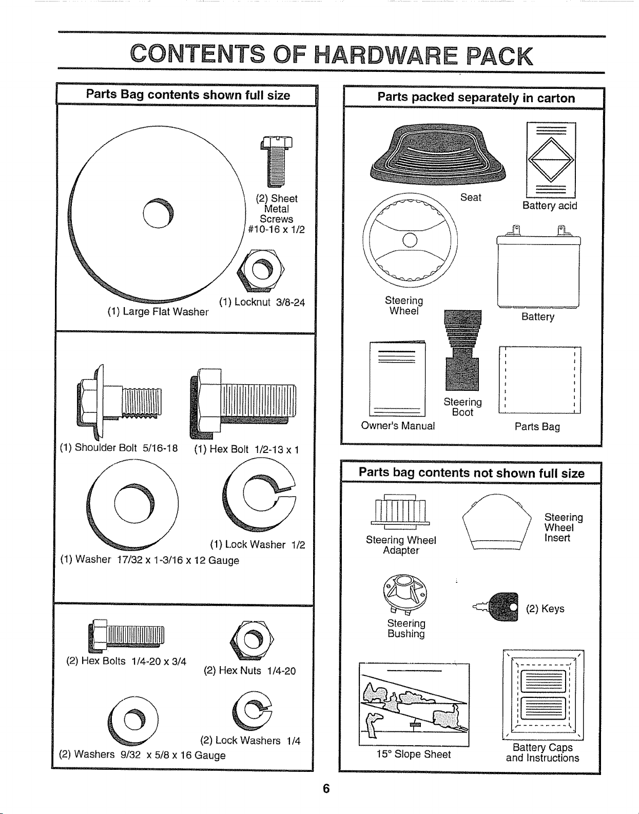
Parts Bag contents shown full size
,n,,H,t] ....................... ...................
©
(2) Sheet
MetaJ
Screws
#10-16 x 1/2
(1) Locknut 3/8-24
(1) Large Flat Washer
........HU_' UU............... : I'UU'"III I"'lll ........
HY--_
(1) Shou=lder Bolt 5/16-18
(1) Hex Bolt !/2-13 x 1
(1) Lock Washer 1/2
(1) Washer' 17/32 x 1-3/16 x 12 Gauge
,,him .......... I uul Ill ..............
(2) Hex Bolts 1/4-20 x 3/4
(2) Hex Nuts 1/4-20
(2) Lock Washers 1/4
(2) Washers 9/32 x 5/8 x 16 Gauge
Hr_ luul'l'u I' nlnHI uulu 'mH" I_'l
HARDWARE PACK
....:.......... ii ......... i"nl,i...........
Parts packed separately in carton
: l,ll,ui ..................
,,ll .................
Seat
Steering
Boot
Battery acid
Steering
Wheel
Owner's Manual
r:-- ........ i
Battery
Parts Bag
u i ......................
Parts bag contents not shown full size
,i, u ............... .................... '
Steering
.... _ ..... Wheel
Steering Wheel Insert
Adapter
6
Steering
Bushing
15° Slope Sheet
(2) Keys
I
r ........
Battery Caps
and Instructions
LY
Your new tractor has been assembled at the factory with exception of those parts left unassembted for shipping purposes,,
To ensure safe and proper operation of your tractor all parts and hardware you assemble must be tightened securely. Use
the correct tools as necessary to insure proper tightness.
TOOLS REQUIRED FOR ASSEMBLY
A socket wrench set will make assembly easien Standard
wrench sizes are listed°
(1) 5/16" wrench
(2) 7/16" wrenches
(1) 1/2" wrench
(1) 3/4" wrench
When right and left hand are mentioned in this manual, it
means when you are in the operating position (seated
behind the steering wheel).
(1) 9/t6" wrench
Tire pressure gauge
Utility knife
TO REMOVE TRACTOR FROM CARTON
UNPACK CARTON
• Remove all accessible loose parts and parts cartons
from carton (See page 6).
o Cut along lines on carton, from top to bottom, all four
corners of carton and lay panels flato
o Check for any additional loose parts or cartons and
remove,,
BEFORE ROLLING TRACTOR OFF SKID
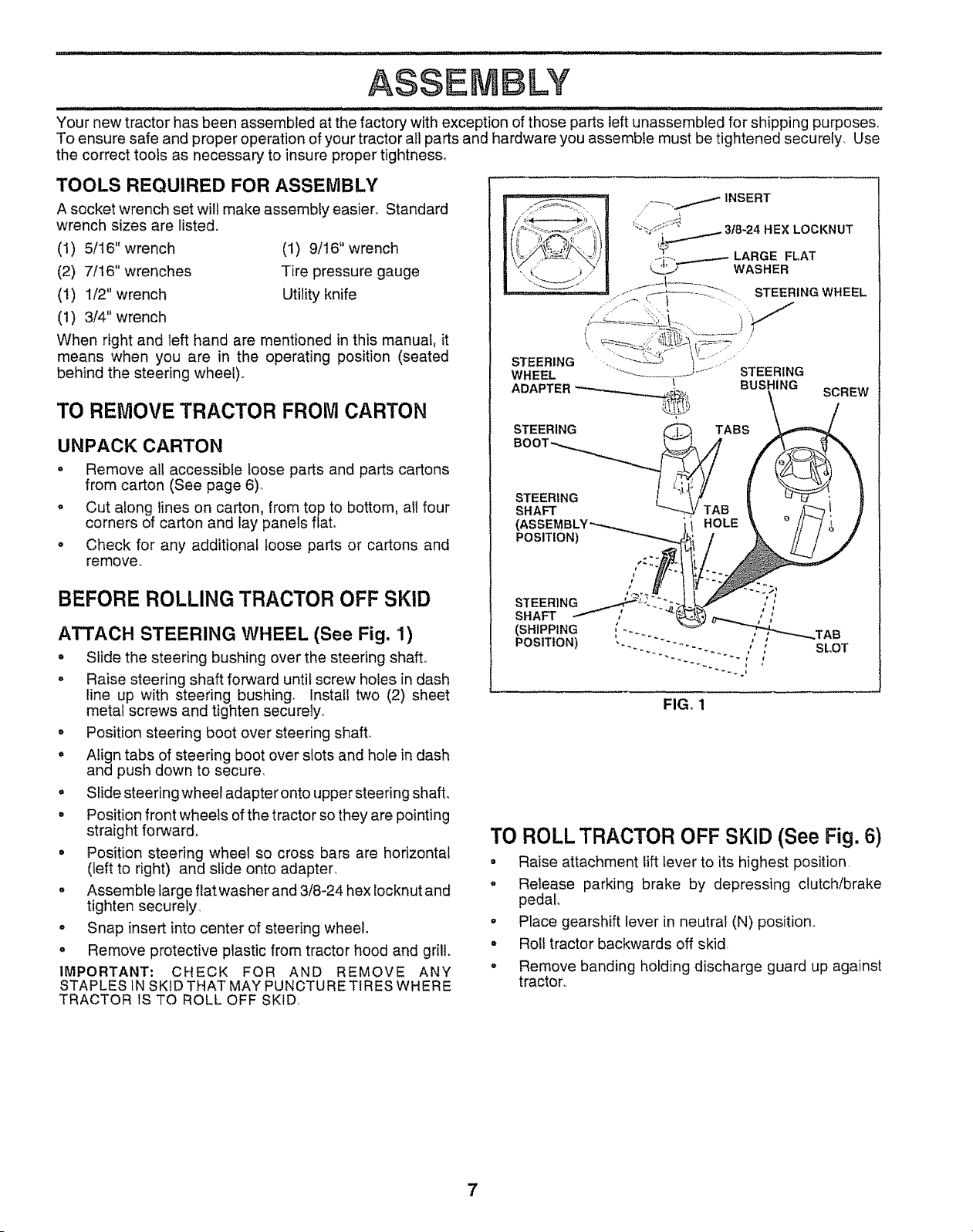
ATTACH STEERING WHEEL (See Fig. '1)
° Slide the steering bushing over the steering shaft°
° Raise steedng shaft forward until screw holes in dash
line up with steering bushing_ Install two (2) sheet
metal screws and tighten securely_
° Position steering boot over steering shaft,,
° Align tabs of steering boot over slots and hole in dash
and push down to secure,
= Slide steering wheel adapter onto upper steed ng shaft,
° Position front wheels of the tractor so they are pointing
straight forward.
° Position steering wheel so cross bars are horizontal
(left to right) and slide onto adapter,
° Assemble large flat washer and 3/8-24 hex locknut and
tighten securely,
° Snap insert into center of steering wheel.
o Remove protective plastic from tractor hood and grill.
IMPORTANT; CHECK FOR AND REMOVE ANY
STAPLES IN SKID THAT MAY PUNCTURE TIRES WHERE
TRACTOR IS TO ROLL OFF SKID,
___ / INSERT
11_,_;:_._.;<:t_ 3/8-24 HEX LOCKNUT
_...._..-. LARGE FLAT
_' WASHER
_'J '_ i.... -'_" =....... STEERING WHEEL
STEERING
WHEEL
BUSHING
FIG, 1
SCREW
SLOT
TO ROLL TRACTOR OFF SKID (See Fig. 6)
• Raise attachment lift lever to its highest position
° Release parking brake by depressing clutch/brake
pedal
o Place gearshift lever in neutral (N) position,,
° Roll tractor backwards off skid,
° Remove banding holding discharge guard up against
tractor.,
7
HOW TO SET UP YOUR TRACTOR
PREPARE BATTERY (See Fig. 2)
CAUTION: Wear eye and face shield,
Wash hands or clothing immediately if
accidentally in contact with battery acid,
Do not smoke. Fumes from charged
battery acid are explosive,
Read the instructions included with the
battery vent caps. Always wear gloves,
clothing and goggles to protect your
hands, skin and eyes.
lul ,Pllinn i II ii i ...............
Your tractor has a battery charging system which is suffi-
cient for normal use, However, periodic charging of the
battery with an automotive charger will extend its life,,
= See instructions packed with vent caps in parts bag,
• Fill battery with acid, Fill each cell until it reaches the
bottom of the vent well& Do not overfill
Allow battery to stand and settle for at least thirty
minutes After standing, check the battery celt acid
level, If below the vent wells, add more acid until the
correct level is reached,
While battery is standing (after adding acid) and later, while
battery is being charged, continue with assembly of unit,,
IMPORTANT: TO MAXIMIZE THE LIFE OF YOUR
BATTERY, IT IS NECESSARY THAT THE BATTERY BE
CHARGED BEFORE USE FAILURE TO CHARGE
BATTERY CAN RESULT IN A SHORTENED BATTERY
LIFE,
• Charge battery at a rate of 6 amperes for I hour. Use
a 12 volt battery charger. Observe all safety precau-
tions required for' battery charging_
o Check the acid level after the battery is charged. If the
acid has fallen below the correct level, add distilled or
iron free water.,
o Install the vent caps to cover the vent wells, Wash the
top of the battery with water to remove any acid, then
wipe dry°
° Check battery case for leakage to make sure that no
damage has occurred in handling°
o Dispose of excess battery acid. Neutralize acid for'
disposal by adding it to two gallons of water in a five
gallon plastic container,. Stir with a wooden or plastic
paddle while adding baking soda until the addition of
more soda causes no more foaming
Follow instructions on how to install battery.
CUT AWAY VIEW
I ..............
VENT CAP
VENT
WELL
BATTERY
CELL ACID
LEVEL
FIG, 2
LY
............................ ,i _ /H ,n ................................
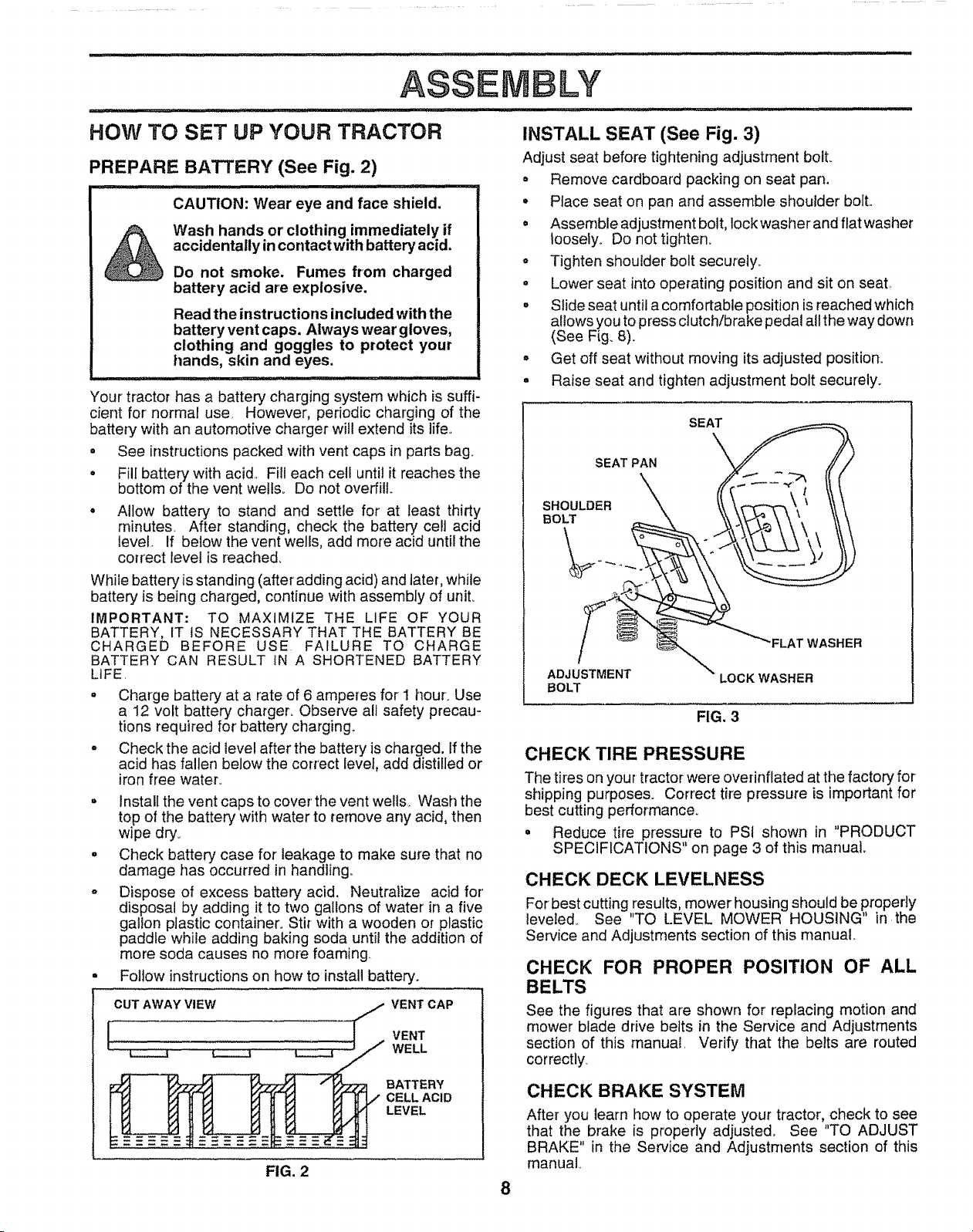
INSTALL SEAT (See Fig. 3)
Adjust seat before tightening adjustment boll
o Remove cardboard packing on seat pan.
• Place seat on pan and assemble shoulder' bolt..
o Assemble adjustment bolt, lock washer and flat washer
Ioosety_ Do not tighten_
° Tighten shoulder bolt securely.
• Lower seat into operating position and sit on seat,
• Stideseat until a comfortable position is reached which
allows you to press clutch/brake pedal all the way down
(See Fig. 8).
° Get off seat without moving its adjusted position.
• Raise seat and tighten adjustment bolt securely.
8
FIG. 3
CHECK TIRE PRESSURE
The tires on your tractor were overinflated at the factory for
shipping purposes. Correct tire pressure is important for
best cutting performance.
° Reduce tire pressure to PSi shown in "PRODUCT
SPECIFICATIONS" on page 3 of this rnanua].
CHECK DECK LEVELNESS
For best cutting results, mower housing should be properly
leveled_ See "TO LEVEL MOWER HOUSING" in the
Service and Adjustments section of this manual,
CHECK FOR PROPER POSITION OF ALL
BELTS
See the figures that are shown for replacing motion and
mower blade drive belts in the Service and Adjustments
section of this manual, Verify that the belts are routed
correctly
CHECK BRAKE SYSTEM
After you learn how to operate your tractor, check to see
that the brake is properly adjusted, See "TO ADJUST
BRAKE" in the Service and Adjustments section of this
manual..
LY
INSTALL BATTERY (See Figs. 4 and 5)
CAUTION: Do not short battery termi-
nals. Before installing battery, remove
metal bracelets, wristwatch bands,
rings, etc.
Positive terminal must be connected
first to prevent sparking from acciden-
tal grounding.
ii Ull, .....
o Lift seat to raised position_
• Open battery box door
° Be sure battery drain tube is attached to battery box.
- Lower battery into battery box with battery terminals
toward front of tractor,.
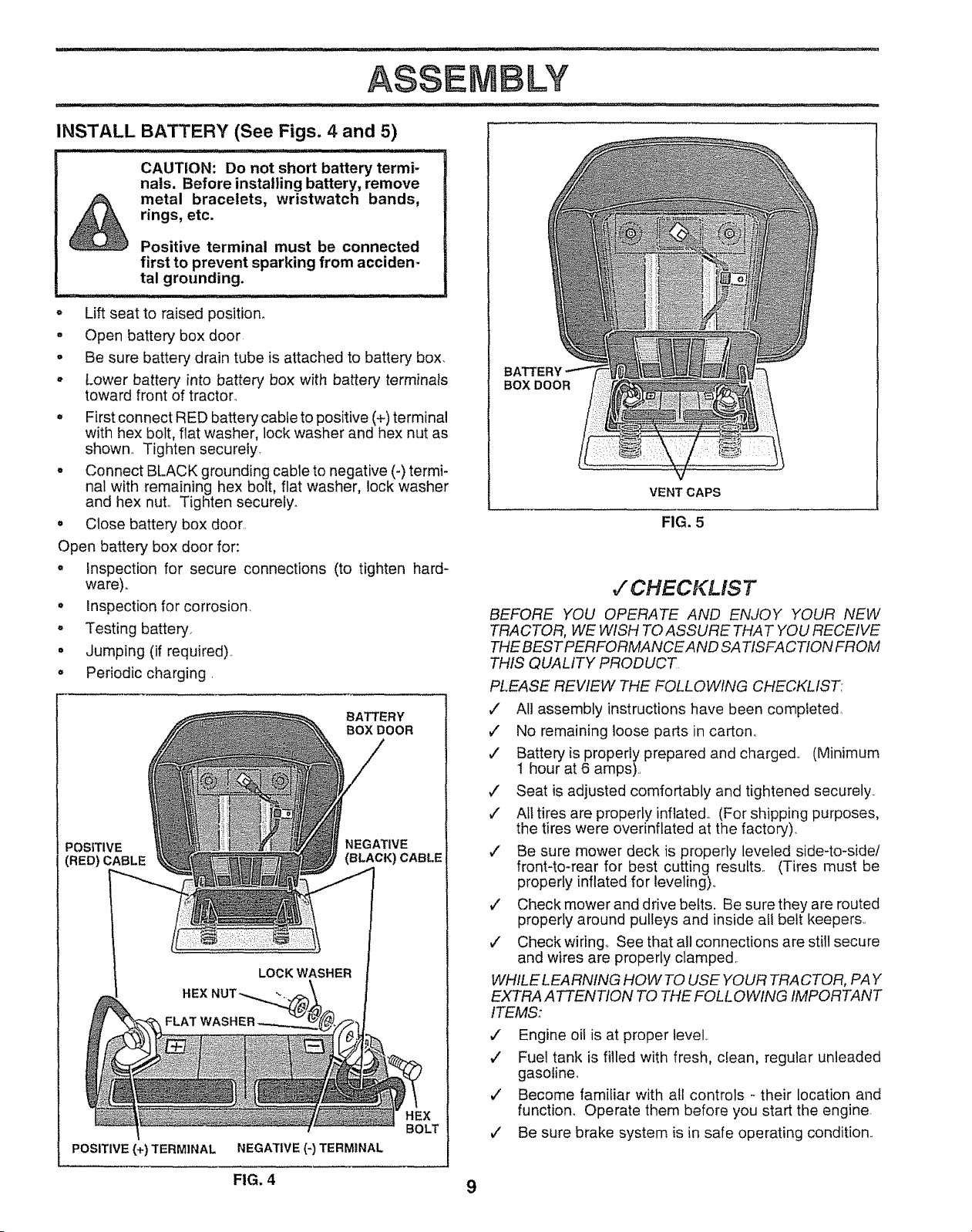
. First connect RED battery cable to positive (+) terminal
with hex bolt, flat washer, lock washer and hex nut as
shown.. Tighten securely_
. Connect BLACK grounding cable to negative (-) termi-
nal with remaining hex bolt, flat washer, lock washer
and hex nut.. Tighten securely.
. Close battery box door.
Open battery box door for:
o Inspection for secure connections (to tighten hard-
ware)..
• Inspection for corrosion.
° Testing battery.
• Jumping (if required)..
° Periodic charging.
BATTERY
BOX DOOR
POSITIVE NEGATIVE
(RED) CABLE (BLACK) CABLE
LOCK WASHER
POSITIVE (+) TERMINAL NEGATIVE (-) TERMINAL
BATTERY
BOX DOOR
VENT CAPS
FIG. 5
v" CHECKLIST
BEFORE YOU OPERATE AND ENJOY YOUR NEW
TRACTOR, WE WISH TO ASSURE THAT YOU RECEIVE
THE BEST PERFORMANCEAND SA TtSFA CTION FROM
THIS QUALITY PRODUCT
PLEASE REVIEW THE FOLLOWING CHECKLIST:
v" All assembly instructions have been completed
v" No remaining loose parts in carton_
v' Battery is properly prepared and charged. (Minimum
1 hour at 6 amps)..
J Seat is adjusted comfortably and tightened securely,
,/ All tires are properly inflated. (For shipping purposes,
the tires were overinflated at the factory)..
,/ Be sure mower deck is properly leveled side-to-side/
front4o-rear for best cutting results° (Tires must be
properly inflated for leveling),.
v" Check mower and drive heirs. Be sure they are routed
properly around pulleys and inside all belt keepers,.
,/ Check wiring. See that al! connections are still secure
and wires are properly clamped.
WHILE LEARNING HOW TO USE YOUR TRACTOR, PAY
EXTRA A TTENTION TO THE FOLL OWING IMPORTANT
ITEMS:
v" Engine oil is at proper level,.
,/ Fuel tank is filled with fresh, clean, regular unleaded
gasoline_
J" Become familiar with all controls - their location and
function,, Operate them before you start the engine.
,f' Be sure brake system is in safe operating condition..
FIG. 4 9
,,_i r,ll ,i _, i,l,l,i ................. .............. ii,l,l,l,llllll , ill
OPERATION
u, ii,l,llll ,i ii i .................. ................
KNOW YOUR TRACTOR
READ THIS OWNER'S MANUAL AND SAFETY RULES BEFORE OPERATING YOUR TRACTOR
Compare the illustrations with your tractor to familiarize yourself with the locations of various controls and adjustments° Save
this manual for future reference.
LIGHT SWITCH
THROTTLE/CHOKE
CONTROL
CLUTCHIBRAKE
PEDAL
ATTACHMENT IGNITION
CLUTCH LEVER SWITCH
LIFT LEVER PLUNGER
ATTACHMENT
LIFT LEVER
o
MOWER DECK
HEIGHT ADJUST-
MENT POSITIONS
GEARSHIFT j _1
LEVER
PARKING BRAKE
FIG. 6
Our tractors conform to the safety standards of the American National Standards Institute°
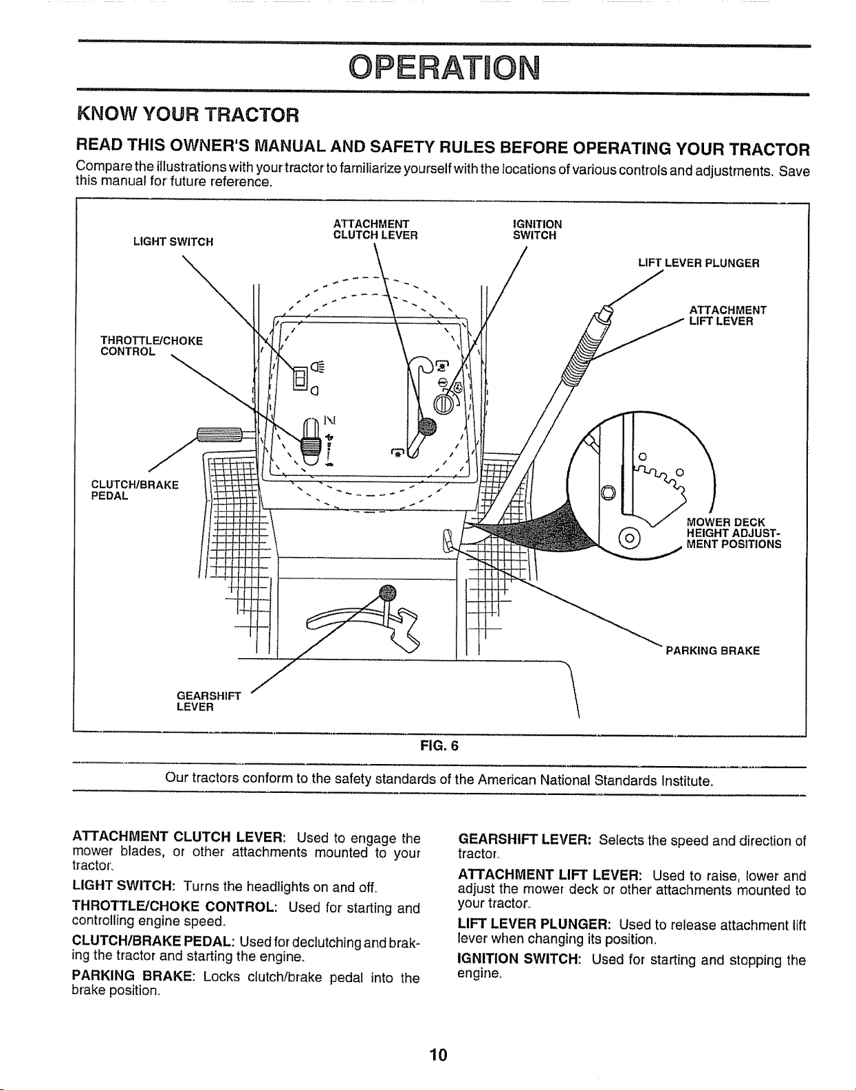
ATTACHMENT CLUTCH LEVER: Used to engage the
mower blades, or other attachments mounted to your
tractor_
LIGHT SWITCH: Turns the headlights on and off_
THROTTLE/CHOKE CONTROL: Used for starting and
controlling engine speed°
CLUTCH/BRAKE PEDAL: Used for declutching and brak-
ing the tractor and starting the engine.
PARKING BRAKE: Locks clutch/brake pedal into the
brake position.
GEARSHIFT LEVER: Selects the speed and direction of
tractor.
ATTACHMENT LIFT LEVER: Used to raise, lower and
adjust the mower deck or other attachments mounted to
your tractor°
LIFT LEVER PLUNGER: Used to release attachment lift
lever' when changing its position,
IGNITION SWITCH: Used for starting and stopping the
engine_
10
OPERATION
The operation of any tractor can result in foreign objects thrown into the eyes, which
can result in severe eye damage. Always wear safety glasses or eye shields while
operating your tractor or performing any adjustments or repairs. We recommend a wide
vision safety mask for over the spectacles or standard safety glasses.
HOW TO USE YOUR TRACTOR
TO SET PARKING BRAKE (See Fig. 7)
= Depress clutch/brake pedal into full "BRAKE" position
and hold.,
Place parking brake lever in "ENGAGED" position and
release pressure from clutch/brake pedal Pedal should
remain in "BRAKE' position,. Make sure parking brake
will hold vehicle secure°
STOPPING (See Fig. 7)
MOWER BLADES -
• Move attachment clutch lever to "DISENGAGED" po-
sition.
GROUND DRIVE -
° Depress clutch/brake pedal into full "BRAKE" position..
• Move gearshift lever to neutral (N) position.
ENGINE -
o Move throttle control to slow (,_) position_
NOTE: Failure to move throttle control to slow (,_)
position and allowing engine to idle before stopping may
cause engine to "backfire"..
° Turn ignition key to "OFF" position and remove key.
Always remove key when leaving tractor to prevent
unauthorized use.
° Never use choke to stop engine°
NOTE: Under certain conditions when tractor is standing
idle with the engine running, hot engine exhaust gases may
cause "browning" of grass. To eliminate this possibility,
always stop engine when stopping tractor on grass areas..
CAUTION= Always stop tractor com-.
pletely, as described above, before leav-
ing the operator's position; to empty
grass catcher, etc.
TO USE THROTTLE CONTROL (See Fig. 7)
Always operate engine at full throttle.
o Operating engine at less than full throttle reduces the
battery charging rate.
o Full throttle offers the best bagging and mower perfor-
mance..
TO MOVE FORWARD AND BACKWARD
(See Fig. 7)
'The direction and speed of movement is controlled by the
gearshift leven
° Start tractor with clutch/brake pedal depressed and
gearshift lever in neutral (N) position.
• Move gearshift lever to desired position,
° S!owfy release clutch/brake pedal to start movement,.
IMPORTANT: BRING TRACTOR TO A COMPLETE STOP
BEFORE SHIFTING OR CHANGING GEARS. FAILURE
TO DO SO WILL SHORTEN THE USEFUL LIFE OF YOUR
TRANSAXLE..
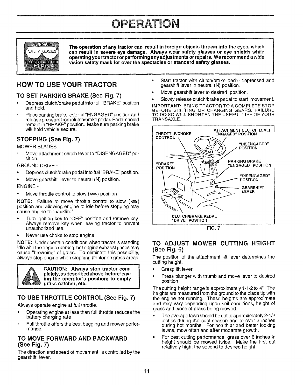
THROTTLE/CHOKE
CONTROL \
ATTACHMENT CLUTCH LEVER
"ENGAGED" POSITION
"DISENGAGED"
POSITION
"BRAKE"
POSITION
PARKING BRAKE
"ENGAGED" POSITION
"DISENGAGED"
POSITION
GEARSHIFT
LEVER
CLUTCHtBRAKE PEDAL
"DRIVE"POSITION
FIG. 7
TO ADJUST MOWER CUTTING HEIGHT
(See Fig. 6)
The position of the attachment lift lever determines the
cutting height.
• Grasp lift lever.
o Press plunger with thumb and move lever to desired
position.
The cutting height range is approximately 1-1/2 to 4", The
heights are measured from the ground to the blade tip with
the engine not running° These heights are approximate
and may vary depending upon soil conditions, height of
grass and types of grass being mowed.
° The average lawn should be cut to approximately 2-1/2
inches during the cool season and to over 3 inches
during hot months., For healthier and better looking
lawns, mow often and after moderate growth,.
° For best cutting performance, grass over 6 inches in
height should be mowed twice_ Make the first cut
relatively high; the second to desired height,,
1'1
OPERATION
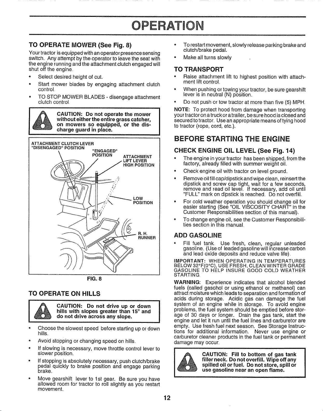
TO OPERATE MOWER (See Fig. 8)
Your tractor isequipped with an operator presence sensing
switch. Any attempt by the operator to leave the seat with
the engine running and the attachment clutch engaged wilt
shut off the engine
o Select desired height of cut.
o Start mower blades by engaging attachment clutch
control,
° TO STOP MOWER BLADES- disengage attachment
clutch control.
CAUTION: Do not operate the mower
without either the entire grass catcher,
on mowers so equipped, or the dis-
charge guard in place.
ATTACHMENT CLUTCH LEVER
"DISENGAGED" POSITION
"ENGAGED"
POSITION ATTACHMENT
HIGH POSITION
a.R=
RUNNER
FIG. 8
TO OPERATE ON HILLS
CAUTION: Do not drive up or down
hills with slopes greater than 15° and
do not drive across any slope.
• Choose the slowest speed before starting up or down
hill&
o Avoid stopping or changing speed on hills.
• If slowing is necessary, move throttle control lever' to
slower position.
o if stopping is absolutely necessary, push clutch/brake
edal quickly to brake position and engage parking
rake_
Move gearshift lever to 1st gear. Be sure you have
allowed room for tractor to roll slightly as you restart
movernenL
° To restart movement, slowly release parking brake and
clutch/brake pedal.
= Make allturns slowly
TO TRANSPORT
° Raise attachment lift to highest position with attach-
ment lift control.
° When pushing or towing your tractor, be sure gearshift
lever is in neutral (N) position_
o Do not push or tow tractor at more than five (5) MPH.
NOTE: To protect hood from damage when transporting
you rtractoron a truck or atrailer, be sure hood is closed and
secured to tractor. Use an appropriate means of tying hood
to tractor (rope, cord, etc,).
BEFORE STARTING THE ENGINE
CHECK ENGINE OIL LEVEL (See Fig, 14)
° The engine in your tractor has been shipped, from the
factory, already filled with summer weight oil
° Check engine oil with tractor on level ground..
° Remove oil fill cap/dipstick and wipe clean, reinsert the
dipstick and screw cap tight, wait for a few seconds,
remove and read oil level. If necessary, add oil until
"FULL" mark on dipstick is reached° Do not overfill.
° For cold weather operation you should change oil for
easier starting (See "OIL. VISCOSITY CHART" in the
Customer' Responsibilities section of this manual).
° To change engine oil, see the Customer Responsibili-
ties section in this manual,
ADD GASOLINE
° Fill fuel tank Use fresh, clean, regular unleaded
gasoline. (Use of leaded gasoline will increase carbon
and lead oxide deposits and reduce valve life),
IMPORTANT: WHEN OPERATING IN TEMPERATURES
BELOW 32°F(0°C), USE FRESH, CLEAN WINTER GRADE
GASOLINE TO HELP INSURE GOOD COLD WEATHER
STARTING.
WARNING: Experience indicates that alcohol blended
fuels (called gasohol or using ethanol or methanol) can
attract moisture which leads to separation and formation of
acids during storage_ Acidic gas can damage the fuel
system of an engine while in storage. To avoid engine
problems, the fuel system should be emptied before stor-
age of 30 days or longer. Drain the gas tank, start the
engine and let it run until the fuel lines and carburetor are
empty. Use fresh fuel next season. See Storage instruc-
tions for additional information. Never use engine or
carburetor cleaner products in the fuel tank or permanent
damage may occur°
CAUTION: Fill to bottom of gas tank
filler neck. Do not overfill. Wipe off any
spilled oil or fuel. Do not store, spill or
use gasoline near an open flame.
12
OPERATUO
TO START ENGINE (See Fig. 7)
When starting engine for the first time or if engine has run
out of fuel, it will take extra cranking time to move fuel from
the tank to the engineo
• Depress clutch/brake pedal and set parking brake.
, Place gearshift lever in neutral (N) position.
o Move attachment clutch to "DISENGAGED" position
° Move throttle control lever to choke (1\1) position for
cold engine start. For warm engine start, move throttle
control to fast (,_) position
• insert key into ignition and turn keyclockwise to"START"
position and release key as soon as engine starts. Do
not run starter continuously for more than fifteen
seconds per minute. If engine does not start after
several attempts, move throttle control to fast (,_)
position, wait a few minutes and try again_
• When engine starts, move throttle control to desired
position_
• Allow engine to warm up for a few minutes before
engaging drive or attachments..
NOTE: If at a high altitude (above 3000 feet) or in cold
temperatures (below 32°F), the carburetor fuel mixture
may needto be adjusted for best engine performance. See
"TO ADJUST CARBURETOR" in the Service and Adjust-
ments section of this manual..
NIOWtNG TIPS
° Tire chains cannot be used when the mower housing
is attached to unit
= Mower should be properly leveled for best mowing
performance° See "TO LEVEL MOWER HOUSING" in
the Service and Adjustments section of this manual.
• Use the runner on the right hand side of mower as a
guide. The blade cuts approximately an inch outside
the runner (See Fig, 8)
° The left hand side of mower should be used for trim-
ming.
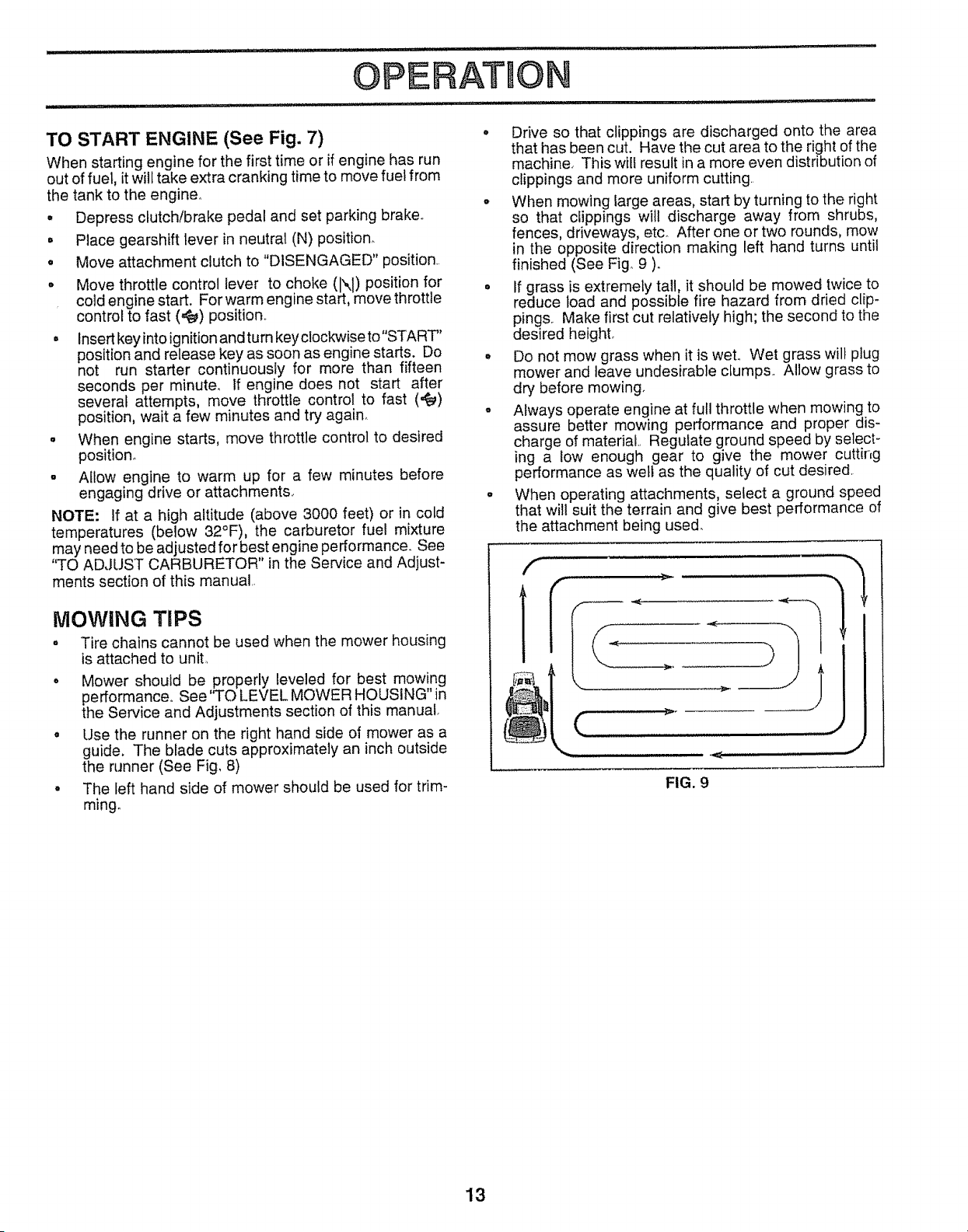
Drive so that clippings are discharged onto the area
that has been cut. Have the cut area to the right of the
machine_ This will result in a more even distribution of
clippings and more uniform cutting
When mowing large areas, start by turning to the right
so that clippings will discharge away from shrubs,
fences, driveways, etc. After one or two rounds, mow
in the opposite direction making left hand turns until
finished (See Fig 9 ).
If grass is extremely tall, it should be mowed twice to
reduce load and possible fire hazard from dried clip-
pings Make first cut relatively high; the second to the
desired height°
Do not mow grass when it is wet Wet grass wilt plug
mower and leave undesirable ctumps Allow grass to
dry before mowing.
Always operate engine at full throttle when mowing to
assure better mow=ng performance and proper dis-
charge of material Regulate ground speed by selecF
ing a low enough gear to give the mower cutting
performance as welt as the quality of cut desired
When operating attachments, select a ground speed
that will suit the terrain and give best performance of
the attachment being used.
FIG. 9
13
CUSTOM
ESPONSJ
CheckBrake Operation 0/ 1_
CheckTire Pressure _f V _'
0/
Checkfor LooseFasteners
R
"SharpeniRep+ace--MowerBlades
LubricationChart
T .Check BatteryLevel/Recharge
0 CIean Battery andTerminals
R CheckTransaxle Cooling
Adjust Blade Belt(s) Tension
Adjust Motion Drive Be_t(s) Tension
Check EngineOil Level V # 0/
ChangeEngine Oil _#' _t2.3
E CleanAir Filter 0/2
N c!eanA,Screen 0/2
G InspectMuffler/SparkArrester
I ReplaceOil Filter (If equipped)
N Cool[ng..F.ins ..........
Clean
Engine
Replace Spark Plug
ReplaceAir Filter PaperCartridge
ReplaceFuel Filter
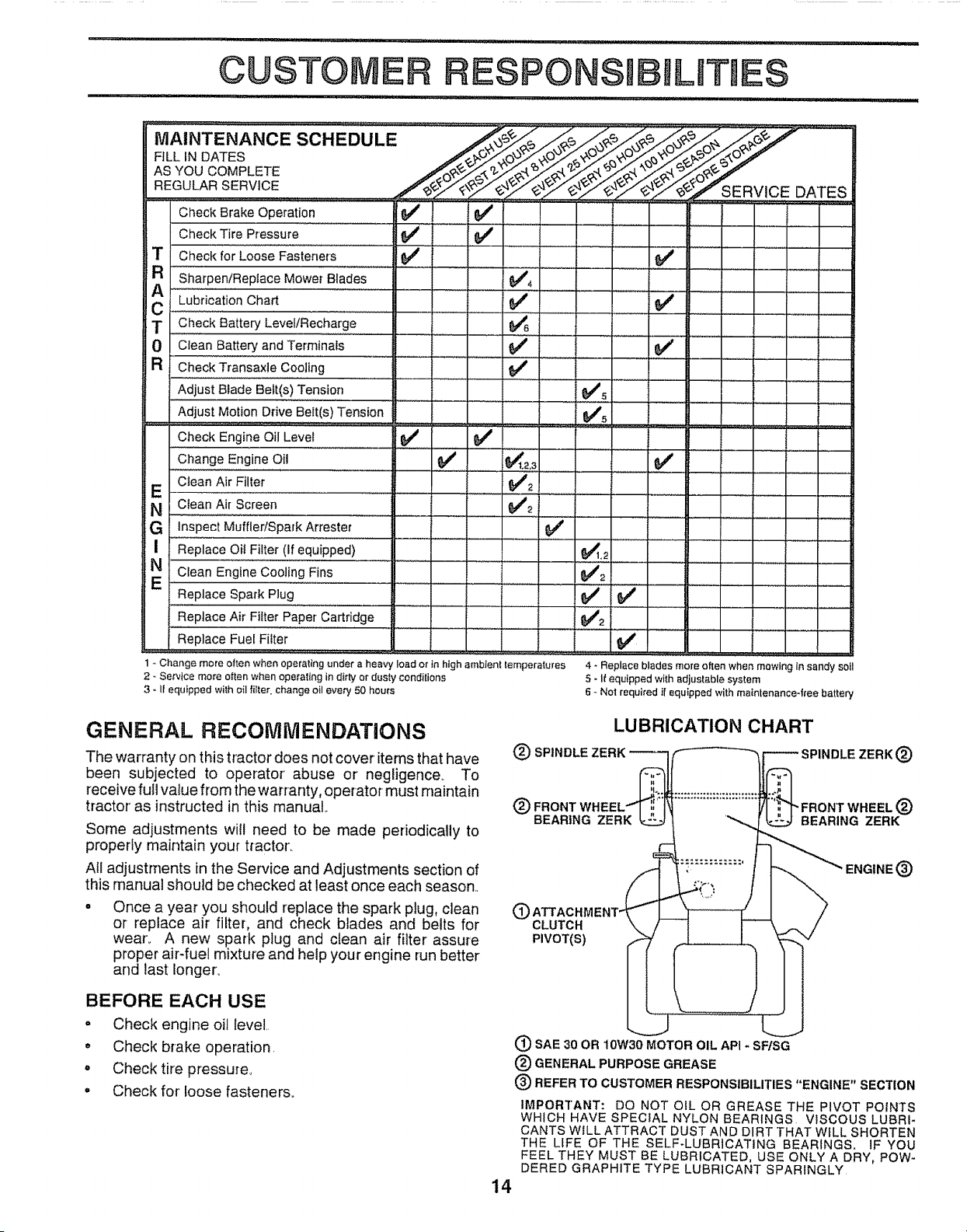
1 +Change more often when operating under a heavy load or In high amb+ent temperatures
2 - Service more often when operallng in dirty or dusty conditions
3 • If equipped with oil filter change oil every 50 hours
0/+
....... i
0/
0/
0/
0/
0/
/5L
0/
..........
0/2
0/ 0/
0/2
0/
4 - Replace blades more often when mowing in sandy sott
5 +If equipped with adjustable system
6 - Not required if equipped with matnlenance4ree battery
GENERAL RECOMiVlENDATiONS
The warranty on this tractor does not cover' items that have
been subjected to operator abuse or negligence+ To
receive full value from the warranty, operator must maintain
tractor' as instructed in this manual..
Some adjustments will need to be made periodically to
properly maintain your tractor,
AII adjustments in the Service and Adjustments section of
this manual should be checked at least once each season..
Once a year you should replace the spark plug. clean
or replace air filter, and check blades and belts for
wear., A new spark plug and clean air filter assure
proper air-fuel mixture and help your engine run better
and last longer.,
LUBRICATION CHART
(_ FRONT
BEARING ZERK
",FRONT WHEEL (_
BEARING ZERK
CLUTCH
PIVOT(S)
®
BEFORE EACH USE
= Check engine oil level.
o Check brake operation.
= Check tire pressuleo
• Check for loose fasteners°
14
(_) SAE 30 OR 10W30 MOTOR OIL API - SF/SG
(_) GENERAL PURPOSE GREASE
® REFER TO CUSTOMER RESPONSIBILITIES "ENGINE" SECTION
IMPORTANT: DO NOTOILOR GREASE THE PIVOT POINTS
WHICH HAVE SPECIAL NYLON BEARINGS. VISCOUS LUBRI-
CANTS WILL ATTRACT DUST AND DIRT THAT W_LL SHORTEN
THE LIFE OF THE SELF-LUBRICATING BEARINGS. IF YOU
FEEL THEY MUST BE LUBRICATED, USE ONLY A DRY, POW-
DERED GRAPHITE TYPE LUBRICANT SPARINGLY
RESPON
TRACTOR
Always observe safety rules when performing any mainte-
nance.
BRAKE OPERATION
If tractor requires more than six (6) feet stopping distance
at high speed in highest gear, then brake must be adjusted.
(See 'q'O ADJUST BRAKE" in the Service and Adjust-
merits section of this manual).
TIRES
• Maintain proper air pressure in all tires (See "PROD-
UCT SPECIFICATIONS" on page 3 of this manual),,
° Keep tires free of gasoline, oil, or insect control chemi-
cals which can harm rubber.
• Avoid stumps, stones, deep ruts, sharp objects and
other hazards that may cause tire damage_
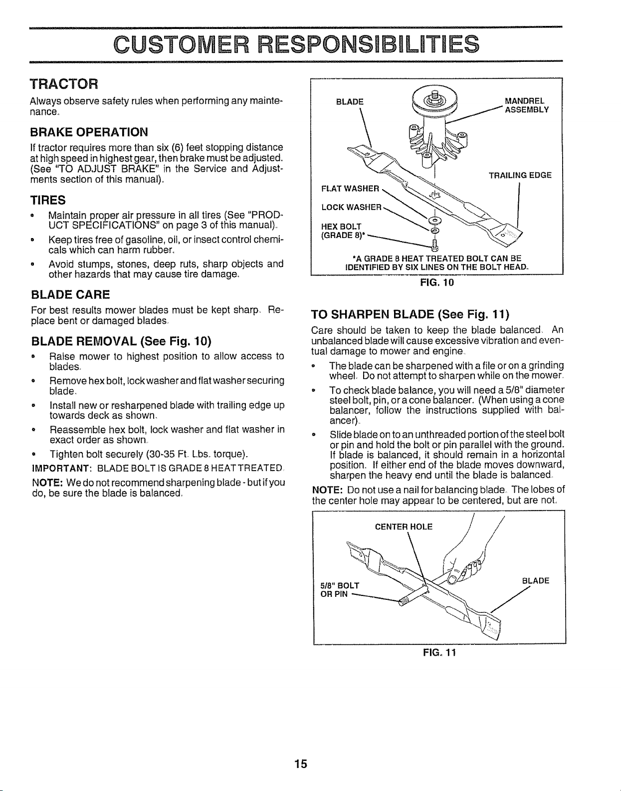
BLADE CARE
For best results mower blades must be kept sharp. Re-
place bent or damaged blades_
BLADE REMOVAL (See Fig. 10)
° Raise mower to highest position to allow access to
btades_
o Remove hex bolt, lock washer and flat washer securing
blade.
o Install new or resharpened blade with trailing edge up
towards deck as shown.
° Reassemble hex bolt, lock washer and flat washer in
exact order as shown
o Tighten bolt securely (30-35 FtoLbso torque).
IMPORTANT: BLADE BOLT tS GRADE8 HEATTREATED,
NOTE: We do not recommend sharpening blade- but if you
do, be sure the blade is balanced,
*A GRADE 8 HEAT TREATED BOLT CAN BE
IDENTIFIED BY StX LINES ON THE BOLT HEAD°
FIG. 10
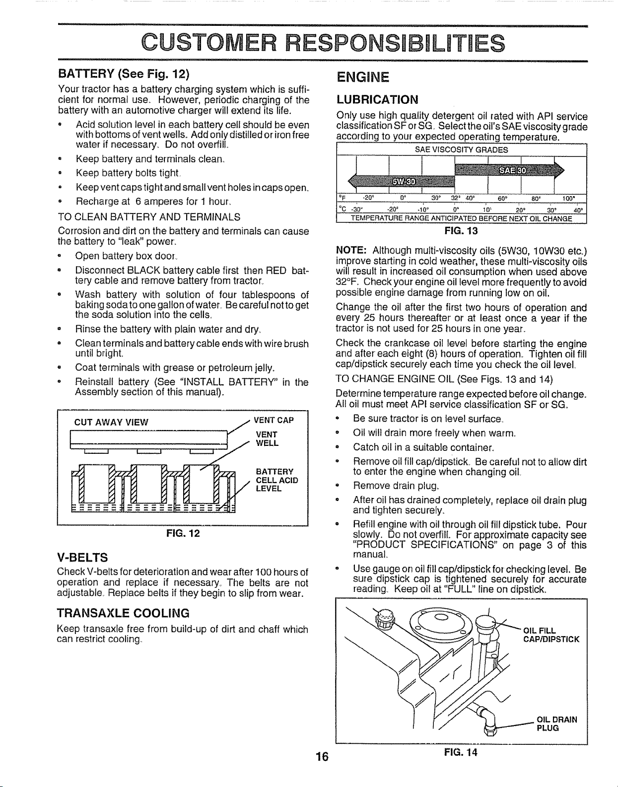
TO SHARPEN BLADE (See Fig, 11)
Care should be taken to keep the blade balanced. An
unbalanced blade will cause excessive vibration and even-
tual damage to mower and engine,
o The blade can be sharpened with a file or on a grinding
wheel. Do not attempt to sharpen while on the mower.
° To check blade balance, you will need a 5/8" diameter
steel bolt, pin, or a cone batancer. (When using a cone
balancer, follow the instructions supplied with bal-
ance r)..
o Slide blade on to an unthreaded portion of the steel bolt
or pin and hold the bolt or pin parallel with the ground.
If blade is balanced, it should remain in a horizontal
position, if either end of the blade moves downward,
sharpen the heavy end until the blade is balanced.
NOTE: Do not use a nail for balancing blade. The lobes of
the center hole may appear to be centered, but are noL
CENTER HOLE
5/8" BOLT
OR PIN
BLADE
FIG. 11
15
CUSTOME
ILITIES
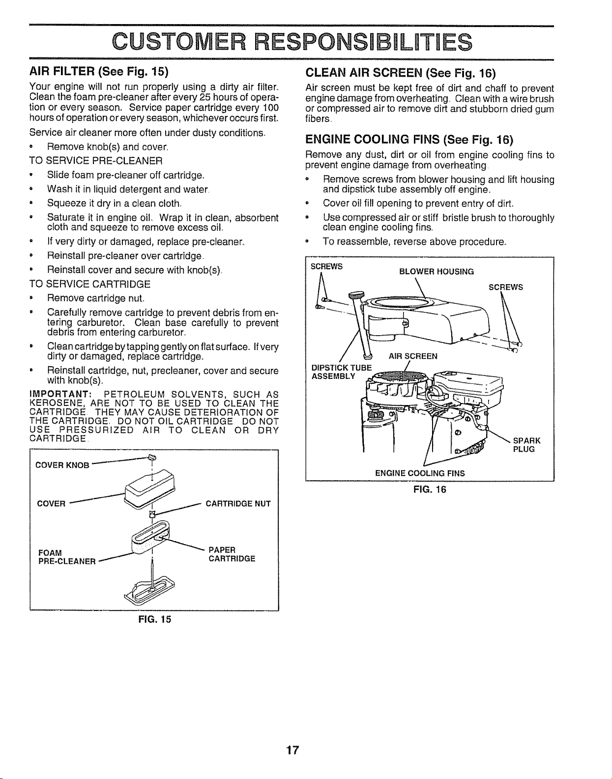
BATTERY (See Fig. 12)
Your' tractor has a battery charging system which is suffi-
cient for normal use,, However, periodic charging of the
battery with an automotive charger wilt extend its life.
o Acid solution level in each battery cell shoutd be even
with bottoms of vent well& Add only distilled or iron free
water if necessary. Do not overfiH,
= Keep battery and terminals clean,.
- Keep battery bolts tight,
o Keep vent caps tight and small vent holes in caps open.
o Recharge at 6 amperes for I hour..
TO CLEAN BATTERY AND TERMINALS
Corrosion and dirt on the battery and terminals can cause
the battery to "leak" power.
o Open battery box door,.
• Disconnect BLACK battery cable first then RED bat-
tery cable and remove battery from tractor_
o Wash battery with solution of four tablespoons of
baking sodato one gallon of water,. Be careful not to get
the soda solution into the cells.
= Rinse the battery with plain water and dry°
° Clean terminals and battery cable ends with wire brush
until bright
- Coat terminals with grease or' petroleum jelly,,
° Reinstall battery (See "INSTALL BATTERY" in the
Assembly section of this manual).
ENGINE
LUBRICATION
Only use high quality detergent oil rated with API service
classification S F or SG Select the oil's SAE viscosity grade
according to your expected operating temperature.
SAE VISCOSITY GRADES
,_F -20" 0_ 30" 32 = 40 = 60 _ 80 = 100"
°c -:_o" o°.............._o'- 2oo ...._o_........40"
TEMPERATURE RANGE ANTICIPATED BEFORE NEXT OIL CHANGE
FIG. 13
NOTE: Although multi-viscosity oils (5W30, 10W30 etc.)
improve starting in cold weather, these multi-viscosity oils
will result in increased oil consumption when used above
32°F, Check your engine oil level more frequently to avoid
possible engine damage from running low on oil.
Change the oil after' the first two hours of operation and
every 25 hours thereafter' or at least once a year if the
tractor is not used for 25 hours in one year,.
Check the crankcase oil level before starting the engine
and after each eight (8) hours of operation,, Tighten oil fill
cap!dipstick securely each time you check the oil level
TO CHANGE ENGINE OIL (See Fig& 13 and 14)
Determine temperature range expected before oil change.
All oil must meet API service classification SF or SG,
CUT AWAY VIEW j/,_ VENT CAP
VENTI WELL
BATTERY
CELL ACID
LEVEL
FIG. 12
V-BELTS
Check V-belts for deterioration and wear after 100 hours of
operation and replace if necessary, The belts are not
adjustable° Replace belts if they begin to slip from wear.
o
o
o
o
o
o
Be sure tractor is on level surface°
Oi! will drain more freely when warm.
Catch oil in a suitable container_
Remove oil fill cap/dipstick_ Be careful not to allow dirt
to enter the engine when changing oil,
Remove drain plug.
After oil has drained completely, replace oil drain plug
and tighten securely,.
Refill engine with oil through oil fill dipstick tube, Pour
slowly. Do not overfill,, For approximate capacity see
"PRODUCT SPECIFICATIONS" on page 3 of this
manual
Use gauge on oil fill cap/dipstick for checking level. Be
sure dipstick cap is tightened securely for accurate
reading_ Keep oil at "FULL" line on dipstick.
TRANSAXLE COOLING
Keep transaxle free from build-up of dirt and chaff which
can restrict cooling.
CAP/DIPSTICK
OIL DRAIN
PLUG
16 FIG. 14
CUSTOME
AIR FILTER (See Fig. 15)
Your engine will not run properly using a dirty air filter°
Clean the foam pre-cleaner after every 25 hours of opera-
tion or every season. Service paper cartridge every 100
hours of operation or every season, whichever occurs first.
Service air cleaner more often under dusty conditions.
o Remove knob(s) and cover.
TO SERVICE PRE-CLEANER
° Slide foam pre-cleaner off cartridge,.
• Wash it in liquid detergent and water.
• Squeeze it dry in a clean cloth.
° Saturate it in engine oil, Wrap it in clean, absorbent
cloth and squeeze to remove excess oil.
• If very dirty or damaged, replace pre-cleanen
o Reinstall pre-cleaner over cartridge_
° Reinstall cover and secure with knob(s),
TO SERVICE CARTRIDGE
° Remove cartridge nuL
, Carefully remove cartridge to prevent debris from en-
tering carburetor. Clean base carefully to prevent
debris from entering carburetor..
, Cfean cartridge by tapping gently on flat surface. Ifvery
dirty or damaged, replace cartridge°
• Reinstall cartridge, nut, precleaner, cover and secure
with knob(s)o
IMPORTANT: PETROLEUM SOLVENTS, SUCH AS
KEROSENE, ARE NOT TO BE USED TO CLEAN THE
CARTRIDGE THEY MAY CAUSE DETERIORATION OF
THE CARTRIDGE, DO NOT OIL CARTRIDGE DO NOT
USE PRESSURIZED AIR TO CLEAN OR DRY
CARTRIDGE.
COVER KNOB
COVER _'_-___ _ CARTRIDGE NUT
ILITIE$
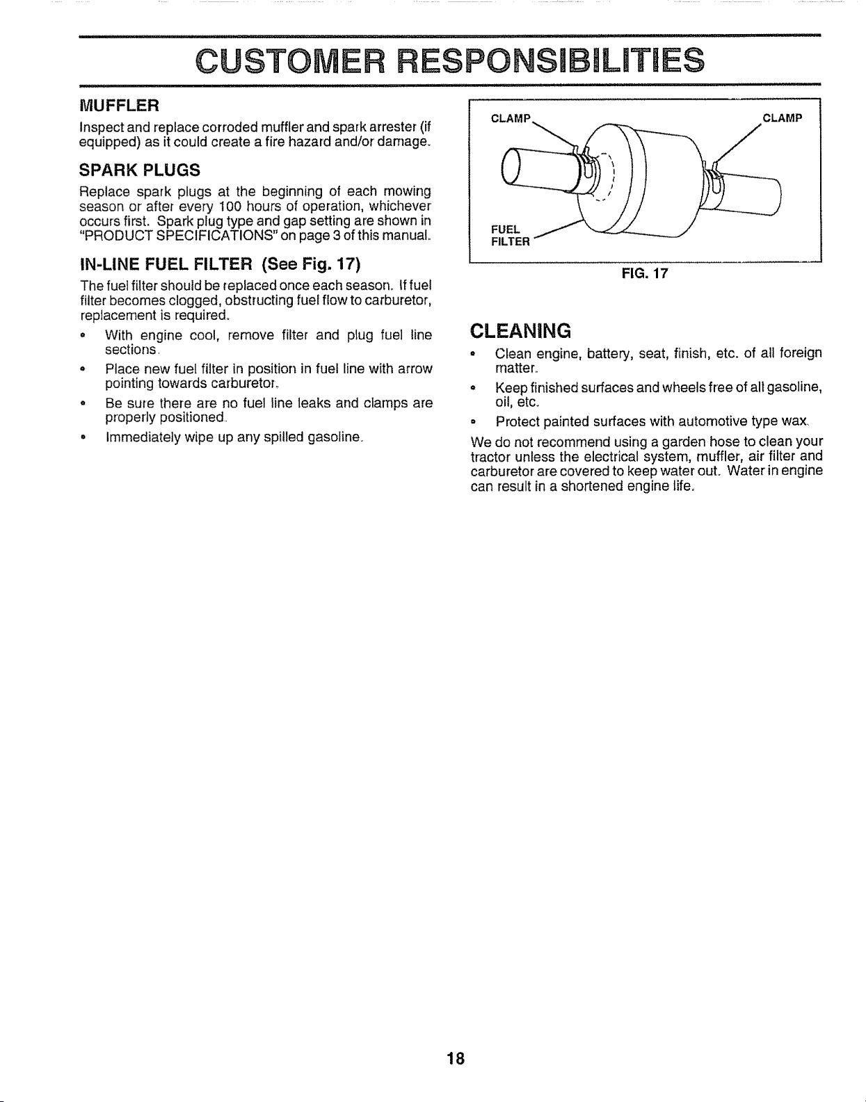
CLEAN AIR SCREEN (See Fig. 16)
Air screen must be kept free of dirt and chaff to prevent
engine damage from overheating.. Clean with a wire brush
or compressed air to remove dirt and stubborn dried gum
fibers.
ENGINE COOLING FINS (See Fig. 16)
Remove any dust, dirt or oil from engine cooling fins to
prevent engine damage from overheating.
o Remove screws from blower housing and lift housing
and dipstick tube assembly off engine.
• Cover oil fill opening to prevent entry of dirt,
• Use compressed air or stiff bristle brush to thoroughly
clean engine cooling fins,
° To reassemble, reverse above procedure.
SCREWS
DIPSTICK TUBE
ASSEMBLY
BLOWER HOUSING
AIR SCREEN
SCREWS
PLUG
ENGINE COOLING FINS
FIG. 16
FIG. 15
'17
CUSTOME
i,
MUFFLER
Inspect and replace corroded muffler and spark arrester (if
equipped) as it could create a fire hazard and/or damage.
SPARK PLUGS
Replace spark plugs at the beginning of each mowing
season or afte_ every 100 hours of operation, whichever
occurs first. Spark plug type and gap setting are shown in
"PRODUCT SPECIFICATIONS" on page 3 of this manual
IN-LINE FUEL FILTER (See Fig. 17)
The fuel filter should be replaced once each season_ If fuel
filter becomes clogged, obstructing fuel flow to carburetor,
replacement is required_
* With engine cool, remove filter and plug fuel line
sections.
° Place new fuel filter in position in fuel line with arrow
pointing towards carburetor..
• Be sure there are no fuel line leaks and clamps are
properly positioned.
° Immediately wipe up any spilled gasoline.
RESPO
CLAMP
FUEL
FILTER
ILITIE$
CLEANING
FIG. 17
CLAMP
° Clean engine, batter:i, seat, finish, etc. of all foreign
matter..
° Keep finished surfaces and wheels free of air gasoline,
oil, etc.
= Protect painted surfaces with automotive type wax.
We do not recommend using a garden hose to clean your
tractor unless the electrical system, muffler, air filter and
carburetor are covered to keep water out. Water in engine
can result in a shortened engine life.
18
$ERVUCE AND ADJUSTMENTS
CAUTION:
o
o
o
0
o
o
BEFORE PERFORMING ANY SERVICE OR ADJUSTMENTS:
Depress clutch/brake pedal fully and set parking brake.
Place gearshift lever in neutral (N) position.
Place attachment clutch in "DISENGAGED" position.
Turn ignition key "OFF" and remove key.
Make sure the blades and all moving parts have completely stopped,
Disconnect spark plug wire from spark plug and place wire where it cannot come in contact with
plug,
TRACTOR
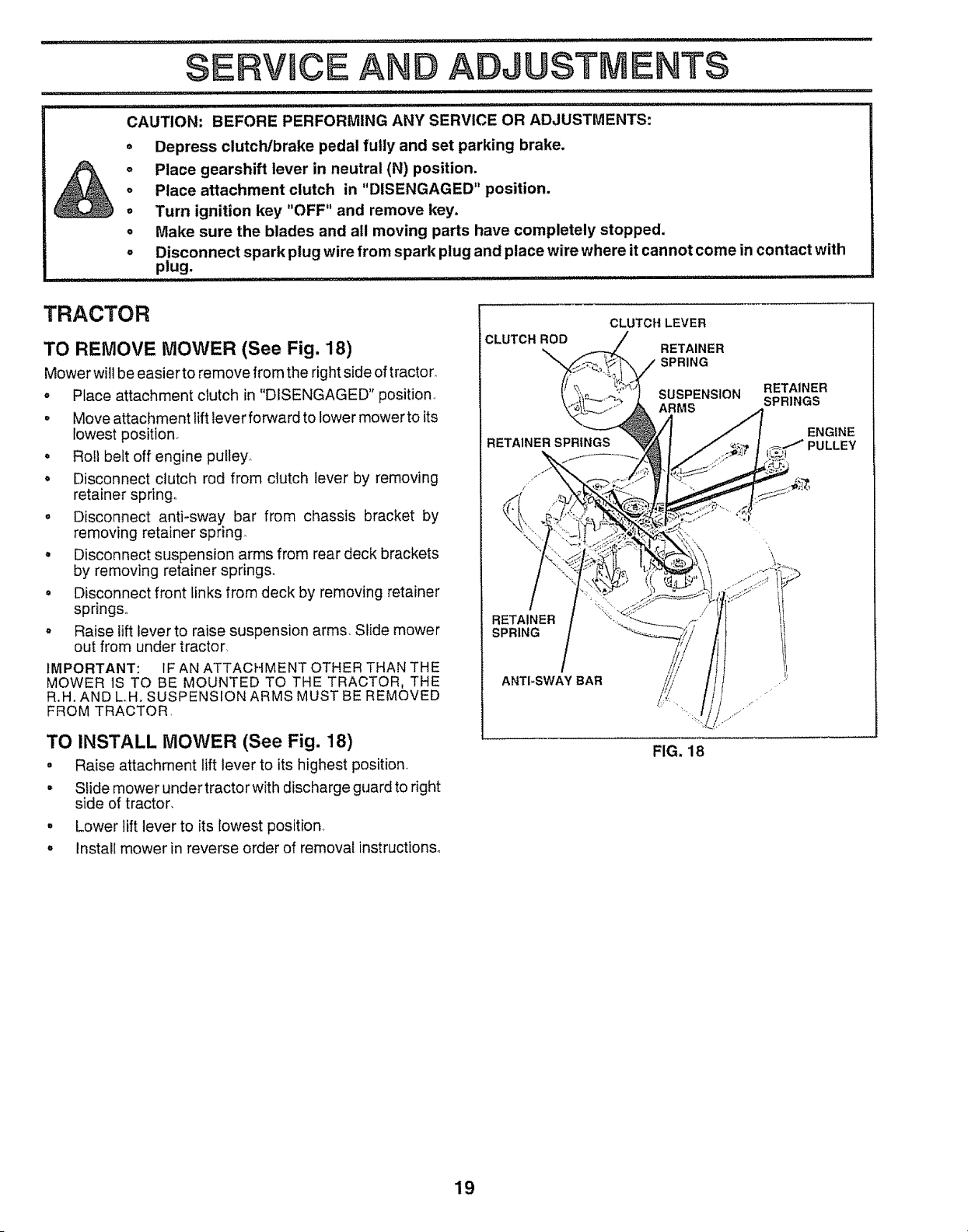
TO REMOVE MOWER (See Fig. 18)
Mower will be easier to remove from the right side of tractor°
= Place attachment clutch in "DISENGAGED" position,
• Move attachment lift lever forward to lower mower to its
lowest position,
. Roll belt off engine pulley_
o Disconnect clutch rod from clutch lever by removing
retainer spring,
o Disconnect anti-sway bar from chassis bracket by
removing retainer spring
o Disconnect suspension arms from rear deck brackets
by removing retainer springs.,
• Disconnect front links from deck by removing retainer
springs.,
o Raise lift lever to raise suspension arms, Slide mower
out from under tractor,
IMPORTANT: 1FAN ATTACHMENT OTHER THAN THE
MOWER lS TO BE MOUNTED TO THE TRACTOR, THE
R.H. AND LH. SUSPENSION ARMS MUST BE REMOVED
FROM TRACTOR,
TO INSTALL MOWER (See Fig. 18)
° Raise attachment lift lever to its highest position,,
• Slide mower undertractorwith discharge guardto right
side of tractor,
° Lower lift lever to its lowest position.
,, install mower in reverse order of removal instructions°
CLUTCH ROD
RETAINER SPRINGS
"N
CLUTCHLEVER
RETAINER
SPRING
;USPENSION
RETAINER
SPRINGS
RETAINER
SPRING
ANTI-SWAY BAR
FIG. 18
19
ERVICE
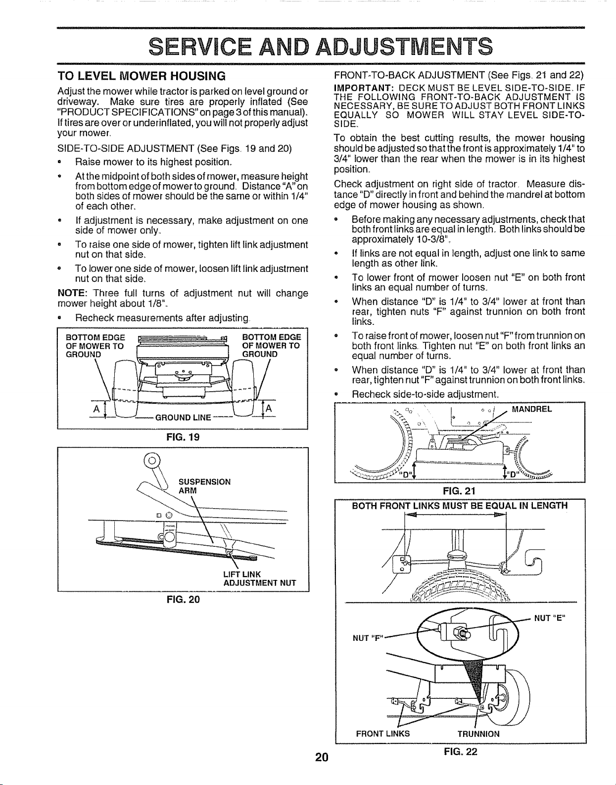
TO LEVEL MOWER HOUSING
AND ADJUSTMENTS
Adjust the mowerwhile tractor is parked on level ground or'
driveway. Make sure tires are properly inflated (See
"PRODUCT SPECIFICATIONS" on page 3 of this manual).
If tires are over or underinflated, you will not properly adjust
your' mower_
SIDE-TO-SIDE ADJUSTMENT (See Figs 19 and 20)
= Raise mower to its highest position.
* At the midpoint of both sides of mower, measure height
from bottom edge of mower to ground_ Distance "A" on
both sides of mower should be the same or within 1/4"
of each other_
o If adjustment is necessary, make adjustment on one
side of mower only.,
. To raise one side of mower, tighten lift link adjustment
nut on that side_
To lower one side of mower, loosen lift link adjustment
nut on that side.
NOTE: Three full turns of adjustment nut wilt change
mower height about 1/8"..
° Recheck measurements after adjusting
FIG, 19
SUSPENSION
ARM
\
LIFT LINK
ADJUSTMENT NUT
FIG. 20
BOTTOM EDGE
OF MOWER TO
GROUND
FRONT-TO-BACK ADJUSTMENT (See Figs 2i and 22)
IMPORTANT: DECK MUST BE LEVEL SIDE-TO-SIDE_ iF
THE FOLLOWING FRONT-TO-BACK ADJUSTMENT IS
NECESSARY, BE SURE TO ADJUST BOTH FRONT LINKS
EQUALLY SO MOWER WiLL STAY LEVEL SIDE-TO-
SIDE,
To obtain the best cutting results, the mower housing
should be adjusted so that the front is approximately 1/4" to
3/4" lower than the rear when the mower is in its highest
position.
Check adjustment on right side of tractor, Measure dis-
tance "D" directly infront and behind the mandrel at bottom
edge of mower housing as shown.
° Before making any necessary adjustments, check that
both front links are equal in length. Both links should be
approximately 10-3/8".,
• tf links are not equal in length, adjust one link to same
length as other link.
° To lower front of mower loosen nut "E" on both front
links an equa! number of turns.
° When distance "D" is 1/4" to 3/4" lower' at front than
rear, tighten nuts "F" against trunnion on both front
links.
° To raise front of mower, loosen nut"F" from trunnion on
both front links. Tighten nut "E" on both front links an
equal number of turn&
o When distance "D" is 1/4" to 3/4" lower at front than
rear, tighten nut"F" against trunnion on both front links_
• Recheck side-to-side adjustmenL
_. % L I _ '-_/ . MANDREL
FIG. 21
BOTH FRONT LINKS MUST BE EQUAL IN LENGTH
NUT "F"
FRONT LINKS TRUNNION
NUT"E"
20 FIGo 22
1
SERVICE AND ADJUSTMENTS
WITH PARKING BRAKE "ENGAGED"
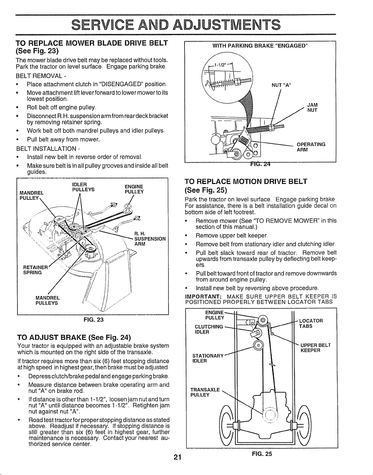
TO REPLACE MOWER BLADE DRIVE BELT
(See Fig. 23)
The mower blade drive belt may be replaced without tools°
Park the tractor on level surface_ Engage parking brake
BELT REMOVAL -
o PIace attachment ctutch in "DISENGAGED" position
° Move attachment lift lever forward to lower mower to its
lowest position.
• Roll belt off engine pultey_
° Disconnect RH. suspension arm from reardeckbracket
by removing retainer spring.
° Work belt off both mandrel pulleys and idler pulleys_
• Pull belt away from mower.
BELT INSTALLATION
• Install new belt in reverse order of removal
° Make sure belt is in all pulley grooves and inside afl belt
guides°
IDLER ENGINE
MANDREL PULLEYS PULLEY
RETAtr
SPRING
MANDREL
PULLEYS
JAM
NUT
i-IL_, Z4.
OPERATING
ARM
TO REPLACE MOTION DRIVE BELT
(See Fig. 25)
Park the tractor on levei surface_ Engage parking brake
For assistance, there is a belt installation guide decal on
bottom side of left footrest,,
° Remove mower (See "TO REMOVE MOWER" in this
section of this manual.)
° Remove upper belt keeper,
° Remove belt from stationary idler and clutching idler
• Pull belt slack toward rear of tractor. Remove belt
upwards from transaxle pulley by deflecting belt keep-
ers
° Pull belt toward front of tractor and remove downwards
from around engine pulley°
° Install new belt by reversing above procedure°
IMPORTANT: MAKE SURE UPPER BELT KEEPER IS
POSITIONED PROPERLY BETWEEN LOCATOR TABS
FIG. 23
TO ADJUST BRAKE (See Fig. 24)
Your tractor is equipped with an adjustable brake system
which is mounted on the right side of the transaxleo
If tractor requires more than six (6) feet stopping distance
at high speed in highest gear, then brake must be adjusted
• Depress clutch/brake pedal and engage parking brake,
o Measure distance between brake operating arm and
nut "A" on brake rod°
Ifdistance is other than 1-I/2", loosen jam nut and turn
nut "A" until distance becomes 1-1/2". Retighten jam
nut against nut "A",,
Road test tractor for proper stopping distance as stated
above Readjust if necessary. If stopping distance is
still greater than six (6) feet in highest gear, further
maintenance is necessary Contact your nearest au-
thorized service center_
PULLEY LOCATOR
CLUTCHING TABS
IDLER
STATIONARY
IDLER
UPPER BELT
KEEPER
TRANSAXLE
PULLEY
21 FIG. 25
SERVWCE
TO ADJUST STEERING WHEEL ALIGNMENT
If steering wheel crossbars are not horizontal (left to right)
when wheels are positioned straight forward, remove steer-
ing wheel and reassemble per instructionsin the Assembly
section of this manual°
FRONT WHEEL TOE-IN/CAMBER
AND ADJUSTMENTS
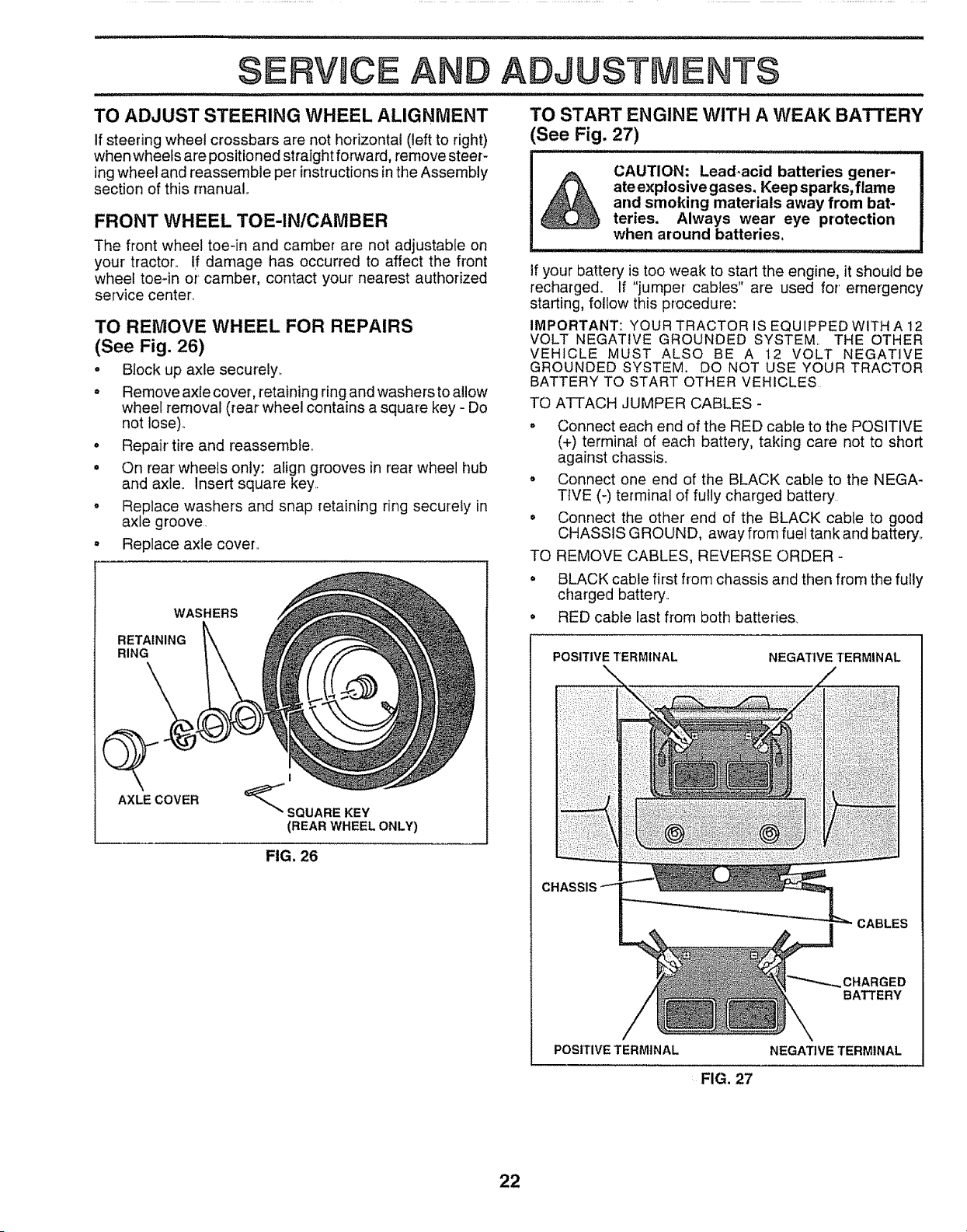
TO START ENGINE WITH A WEAK BATTERY
(See Fig, 27)
The front wheel toe-in and camber are not adjustable on
your tractor_ If damage has occurred to affect the front
wheel toe-in or' camber, contact your nearest authorized
service center,
TO REMOVE WHEEL FOR REPAIRS
(See Fig. 26)
o Block up axle securely._
° Remove axle covet, retaining ring and washers to allow
wheel removal (tear wheel contains a square key - Do
not lose)..
• Repair tire and reassemble°
° On rear wheels only: align grooves in rear wheel hub
and axle.. Insert square key._
o Replace washers and snap retaining ring securely in
axle groove.
, Replace axle cover..
WASHERS
RETAINING
RING
I
_SQUARE KEY
(REAR WHEEL ONLY)
FIG. 26
AXLE COVER
CAUTION: Lead-acid batteries gener-
ate explosive gases. Keep sparks, flame
and smoking materials away from bat=
teries. Always wear eye protection
when around batteries,
if your battery is too weak to start the engine, it should be
recharged. If "jumper cables" are used for' emergency
starting, follow this procedure:
IMPORTANT: YOUR TRACTOR IS EQUIPPED WITH A 12
VOLT NEGATIVE GROUNDED SYSTEM, THE OTHER
VEHICLE MUST ALSO BE A 12 VOLT NEGATIVE
GROUNDED SYSTEM. DO NOT USE YOUR TRACTOR
BATTERY TO START OTHER VEHICLES
TO ATTACH JUMPER CABLES -
o Connect each end of the RED cable to the POSITIVE
(+) terminal of each battery, taking care not to short
against chassis.
o Connect one end of the BLACK cable to the NEGA-
TIVE (-) terminal of fully charged battery
° Connect the other end of the BLACK cable to good
CHASSIS GROUND, away from fuel tank and battery°
TO REMOVE CABLES, REVERSE ORDER -
° BLACK cable first from chassis and then from the fully
charged battery..
• RED cable last from both batteries.
POSITIVE TERMINAL NEGATIVE TERMINAL
CHASSIS
CABLES
CHARGED
BATTERY
POStTIVETERMINAL
NEGATIVE TERMINAL
FIG. 27
22
ERVICE A
ADJUSTMENTS
TO REPLACE HEADLIGHT BULB
o Raise hood.,
o Pull bulb holder out of the hole in the backside of the
grill o
° Replace bulb in holder and push bulb holder securely
back into the hole in the backside of the grill,
o Close hood,,
INTERLOCKS AND RELAYS
Loose or damaged wiring may cause your tractor to run
poorly, stop running, or prevent it from starting.,
° Check wiring. See electrical wiring diagram in Repair
Parts section of this manual,,
TO REPLACE FUSE
Replace with 30 amp automotive-type plug-in fuse° The
fuse holder is located behind the dash,
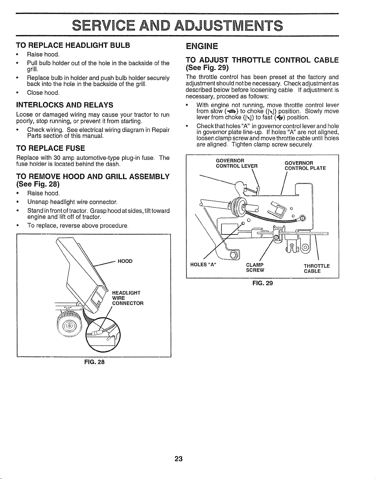
TO REMOVE HOOD AND GRILL ASSEMBLY
(See Fig. 28)
• Raise hood_
° Unsnap headlight wire connector,
o Stand infront of tractor,, Grasp hood at sides, tilt toward
engine and lift off of tractor,
, To replace, reverse above procedure.
HOOD
HEADLIGHT
WIRE
CONNECTOR
ENGRNE
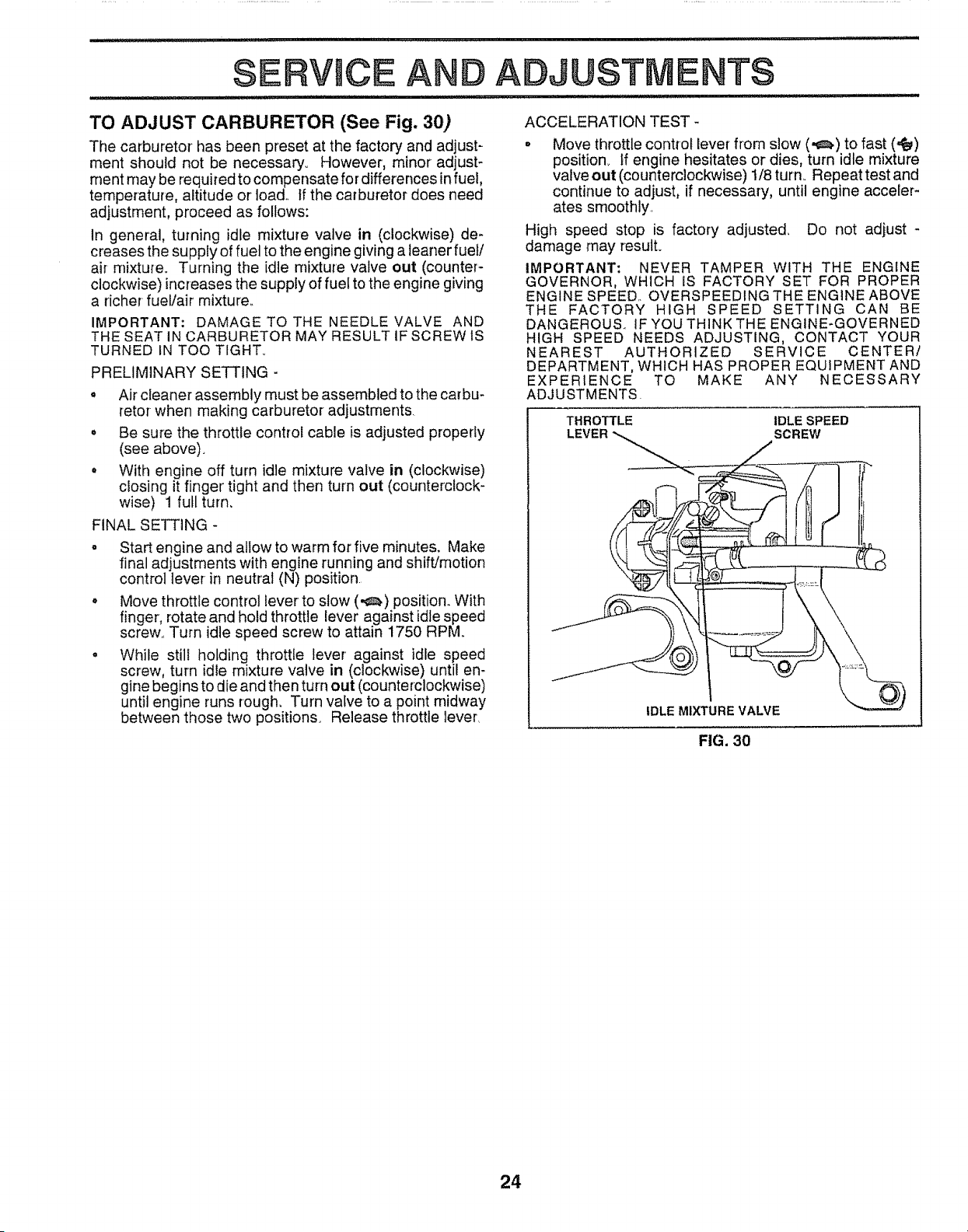
TO ADJUST THROTTLE CONTROL CABLE
(See Fig. 29)
The throttle control has been preset at the factory and
adjustment should not be necessary_ Check adjustment as
described below before loosening cable, If adjustment is
necessary', proceed as follows:
• With engine not running, move throttle control lever
from slow (._) to choke ( X ) position, Slowly move
lever from choke (N) to fast (,_) position_
o Checkthat holes"A" in governorcontrot leverand hole
in governor plate line-upo If holes "A" are not aligned,
loosen clamp screw and move throttle cable until holes
are aligned_ Tighten clamp screw securely,
GOVERNOR
CONTROLLEVER
GOVERNOR
CONTROL PLATE
O
O
HOLES "A" CLAMP THROTTLE
SCREW CABLE
FIG. 29
FIG. 28
23
SERVUCE AND ADJUSTMENTS
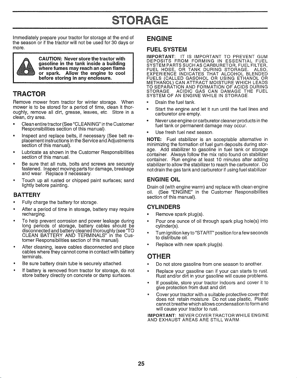
TO ADJUST CARBURETOR (See Fig. 30)
The carburetor has been preset at the factory and adjust-
ment should not be necessary_ However, minor adjust-
ment may be required to compensate for differences in fuel,
temperature, altitude or load. tf the carburetor does need
adjustment, proceed as follows:
In general, turning idle mixture valve in (clockwise) de-
creases the supply of fuel to the engine giving a teaner fuel/
air mixture. Turning the idle mixture valve out (counter-
clockwise) increases the supply of fuel to the engine giving
a richer fuel/air mixture°
IMPORTANT: DAMAGE TO THE NEEDLE VALVE AND
THE SEAT IN CARBURETOR MAY RESULT IF SCREW IS
TURNED IN TOO TIGHT°
PRELIMINARY SE'f-I'ING -
o Air cleaner assembly must be assembled to the carbu-
retor when making carburetor adjustments
• Be sure the throttle control cable is adjusted properly
(see above).
° With engine off turn idle mixture valve in (clockwise)
closing it finger' tight and then turn out (counterclock-
wise) 1 full turn.
FINAL SETTING -
o Start engine and allow to warm for five minutes. Make
final adjustments with engine running and shift/motion
control lever in neutral (N) position
° Move throttle control leverto slow (,,_) position,, With
finger, rotate and hold throttle lever against idle speed
screw,, Turn idle speed screw to attain 1750 RPM
° While still holding throttle lever' against idle speed
screw, turn idle mixture valve in (clockwise) until en-
gine begins to die and then turn out (counterclockwise)
until engine runs rough. Turn valve to a point midway
between those two positions. Release throttle lever,
ACCELERATION TEST -
° Move throttle control lever from slow (,,_) to fast (,_)
position_ ff engine hesitates or dies, turn idle mixture
valve out (counterclockwise) 1/8 turn. Repeat test and
continue to adjust, if necessary, until engine acceler-
ates smoothly.
High speed stop is factory adjusted, Do not adjust -
damage may result.
IMPORTANT: NEVER TAMPER WITH THE ENGINE
GOVERNOR, WHICH IS FACTORY SET FOR PROPER
ENGINE SPEED.. OVERSPEEDING THE ENGINE ABOVE
THE FACTORY HIGH SPEED SETTING CAN BE
DANGEROUS.. IF YOU THINK THE ENGINE-GOVERNED
HIGH SPEED NEEDS ADJUSTING, CONTACT YOUR
NEAREST AUTHORIZED SERVICE CENTER/
DEPARTMENT, WHICH HAS PROPER EQUIPMENT AND
EXPERIENCE TO MAKE ANY NECESSARY
ADJUSTMENTS.
THROTTLE IDLE SPEED
SCREW
IDLE MIXTURE VALVE
FIG. 30
24
STORAGE
Immediately prepare your tractor for storage at the end of
the season or if the tractor wilt not be used for 30 days or
more..
&
CAUTION: Never store the tractor with
gasoline in the tank inside a building
where fumes may reach an open flame
or spark, Allow the engine to cool
before storing in any enclosure,
TRACTOR
Remove mower from tractor for winter storage.. When
mower is to be stored for a period of time, clean it thor-
oughly, remove all dirt, grease, leaves, etc. Store in a
clean, dry area.
o Clean entire tractor (See"CLEANtNG" in the Customer
Responsibilities section of this manuat),
° Inspect and replace belts, if necessary (See belt re-
placement instructions in the Service and Adjustments
section of this manual).
° Lubricate as shown in the Customer Responsibilities
section of this manual.
o Be sure that all nuts, bolts and screws are securely
fastened. Inspect moving parts for damage, breakage
and wear. Replace if necessary.
• Touch up all rusted or chipped paint surfaces; sand
lightly before painting.
BATTERY
• Fully charge the battery for storage_
• After a period of time in storage, battery may require
recharging.
• To help prevent corrosion and power leakage during
long periods of storage, battery cables should be
disconnected and battery cleaned thoroughly (see "TO
CLEAN BATTERY AND TERMINALS" in the Cus-
tomer Responsibilities section of this manual).
° After cleaning, leave cables disconnected and place
cables where they cannot come in contact with battery
terminals.
• Be sure battery drain tube is securely attached,.
. If battery is removed from tractor for storage, do not
store battery directly on concrete or damp surfaces°
ENGINE
FUEL SYSTEM
IMPORTANT: IT IS IMPORTANT TO PREVENT GUM
DEPOSITS FROM FORMING IN ESSENTIAL FUEL
SYSTEM PARTS SUCH AS CARBURETOR, FUEL FILTER,
FUEL HOSE, OR TANK DURING STORAGE. ALSO,
EXPERIENCE INDICATES THAT ALCOHOL BLENDED
FUELS (CALLED GASOHOL OR USING ETHANOL OR
METHANOL) CAN ATTRACT MOISTURE WHICH LEADS
TO SEPARATION AND FORMATION OF ACIDS DURING
STORAGE_ ACIDIC GAS CAN DAMAGE THE FUEL
SYSTEM OF AN ENGINE WHILE IN STORAGE
o Drain the fuel tank..
• Start the engine and let it run until the fuel lines and
carburetor are empty.
° Never use engine or carburetor cleaner products in the
fuel tank or permanent damage may occun
o Use fresh fuel next season..
NOTE: Fuel stabilizer is an acceptable alternative in
minimizing the formation of fuel gum deposits during stor-
age., Add stabilizer to gasoline in fuel tank or storage
container. Always follow the mix ratio found on stabilizer
containen Run engine at least 10 minutes after adding
stabilizer to allow the stabilizer to reach the carburetor. Do
not drain the gas tank and carburetor if using fuel stabilizer
ENGINE OIL
Drain oil (with engine warm) and replace with clean engine
oil, (See "ENGINE" in the Customer Responsibilities
section of this manual),,
CYLINDERS
° Remove spark plug(s),.
• Pour one ounce of oil through spark plug hole(s) into
cylinder(s)..
° Turn ignition key to "START" position fo r a few seconds
to distribute oil..
• Replace with new spark plug(s).
OTHER
o Do not store gasoline from one season to another=.
o Replace your gasoline can if your can starts to rust..
Rust and!or dirt in your gasoline will cause problems_
° If possible, store your tractor indoors and cover it to
give protection from dust and dirt
° Cover your tractor with a suitable protective cover that
does not retain moisture.. Do not use plastic. Plastic
cannot breathe which allows condensation to form and
wilt cause your tractor to rusL
IMPORTANT: NEVER COVER TRACTORWH1LE ENGINE
AND EXHAUST AREAS ARE STILL WARM
25

PROBLEM
i ....................................
Will not start
CAUSE
1 Out of fuel
2 Engine not "CHOKED" propedy,,
3 Engine flooded
4 Bad sparkplug_
5 Dirty air fitter
6 Dirty fuet fitter
7, Water in fuel
8. Loose or damaged wiring
9. Carburetor outof adjustment.
10 Engine valves out of adjustment
CORRECTION
I. Fi!l fuel tank
2 See "TO START ENGINE" in Operation section
3, Wait several minutes before attempting to start.
4. Replace spark plug.
5 Ctean!reptace air filter.
6 Replace fuel fitter
7. Drain fuel tank and carburetor, refill tank with fresh
gasoline and replace fuel fi_ter
8 Check all wiring
9 Contact an authorized service center/departmen[
t0, Contact an authorized service center/department,
Hard to start
Engine will not turn over
Engine clicks but will not
start
Loss of power
t Dirty air fitter
2 Bad sparkptug
3 Weaker dead battery
4 Dirt':/fuel fiIter
5 Stale or dirty fuel
6. Loose or damaged wiring
7 Carburetor out of adjustment.
8 Engine valves out of adjustment
1. Clutch!brake pedal not depressed
2 Attachment clutchis engaged
3 Weak or dead battery.
4 Brown fuse.
5 Corroded battery terminals
6. Loose or damaged wiring
7 Faulty ignition switch
8. Faulty solenoid or starter
9, Faulty operator presence switch(es).
1 Weak or dead battery
2. Corroded batteryterminals_
3, Loose or damaged wiring.
4. Faulty solenoid or starter
1 Cutting too much grass/too fast
2. Throttle in "CHOKE" position,
3, Build-up of grass, reaves and trash under mower.
1 Clean!replace air tilter,.
2 Replace spark plug
3 Recharge or replace battery
4 Replace fuel filter
5 Drain fuel tank and refill with fresh gasotine,
6, Check all wiring
7, Contact an authorized service center/department
8, Contact an authorized service center/department
1 Depress clutch!brake pedal
2 Disengage attachment clutch
3, Recharge or replace battery,
4 Replace fuse.
5 Clean battery !erminals
6 Checka!{ widng.
7 Check!replace Ignition switch
8, Check/replace solenoid or starter
9 Contact an authorized service center/department
t Recharge or replace battery,,
2 Clean battery terminals
3 Check all wiring,
4, Check/replace solenoid or starter
1 Set in "Higher Cut" position/reduce speed
2 Adjust throttle control
3 Clean underside of mower housing.
Excessive vibration
4 Dirty air filter,
5 Low oit level/dirty oil.
6 Faulty spark plug.
7. Dirty fuet filter,
8 State or dirty fuel
9 Water in fuel
10. Spark plug wire toose.
1I. Dirty engine air screen/fins
t2, Dirty/clogged muffler
I3. Loose or damaged wiring,
i4 Carburetor out of adjustment.
t5 Engine vatves out of adjustment
1. Worn, bent or loose blade.,
2 Bent blade mandrel
3. Loose/damaged part(s).
4_ Clean/replace air filter
5, Check oil revel/change oil
6 Clean and regap or change spark plug,
7 Reptace fuet fitter
8 Drain fuel tank and refitl with fresh gasoline,
9 Drain fuel tank:and carburetor, refill tank with fresh
gasoline and reptace fuel fitter
10, Connect and tighten spark plug wire
11 Clean engine air screen!fins
12 Clean/replace muffler
13 Check all wiring,
t4. Contact an authorized service center/department.
15 Contact an authorized service center/department
1. Replace blade, Tighten blade bolt
2, Replace blade mandrel,
3,, Tighten loose part(s). Replace damaged parts
26

PROBLEM
Engine continues to run
when operator leaves seat
with attachment clutch
engaged
Poor cut. uneven
Mower blades will not
rotate
Poor grass discharge
Headlight(s) not working
(if so equipped)
Battery will not charge
Engine "backfires"
when turning engine
"OFF"
CAUSE
1, Faultyoperator-safety presence control system
1. Worn, bent orloose blade
2 Mowerdeck nottevel
3 Buildup of grass, leaves, and trash under mower.
4 Bent blade mandrel
5 Clogged mower deck vent holes from buildup of
grass, leaves, and trash around mandrels.
t Obstruction in clutch mechanism
2 VVorn/damaged mower drive bell
3, Frozen idler putley
4 Frozen blade mandrel.
1. Engine speed too stow
2. Travel speed too fast
3. Wet grass
4 Mower deck not level
5. Low/uneven tire air pressure
6 Worn, bent or loose blade
7. Buildup of grass, leaves and trash under mower
8. Mower drive belt worn
9, Blades Improperly fnstalled
10. lmproperblades used
1 ! Clogged mower deck vent holes from buildup of
grass, leaves, and trash around mandrels
t Sw{tch is "OFF".
2, Bulb(s) burned out
3. Faulbi light switch.
4, Loose or damaged wiring
5 Blown fuse,
1 Bad battery cell(s)
2 Poor cable connections
3 Faulty regulator (if so equipped)
4, Fautt'i alternator,
1
Engine throttle control not set at "SLOW"
position for 30 seconds before stopping engine
CORRECTION
......... i.,i i Ji
1 Checkwlring, switches and connections If not
corrected, contact an authorized service center!
department,
1 Replace blade Tighten blade bolt
2 Level mower deck
3 Clean underside of mower housing
4. Replace blade mandrel
5 Clean around mandrels to open vent holes,
1 Remove obstruction
2 Replace mowerddve belt
3 Replace idler pulley
4 Replace blade mandrel,
t Place throttle control in "FAST" position
2 Shift to slower speed,
3 Allow grass to dry beiore mowing,
4 Level mower deck
5 Check tires for proper air pressure
6 Replace/sharpen blade Tighten blade bolt
7 Clean underside of mower housing
8 Repface mower drive belt
9 Reinstall blades sharp edge down
t0. Replace with blades listed in this manual
1 ! Clean around mandrels to open vent holes
1 Turn switch "ON"
2, Replace bulb(s),
3. Check/replace light switch
4 Check wiring and connections..
5 Replace fuse
t Replace battery,
2 Check/clean all connections
3 Replace regulator
4 Replace alternator
Move throttle control to "SLOW" position and allow
to idle for 30 seconds before stopping engine
27

SERVICE NOT
28
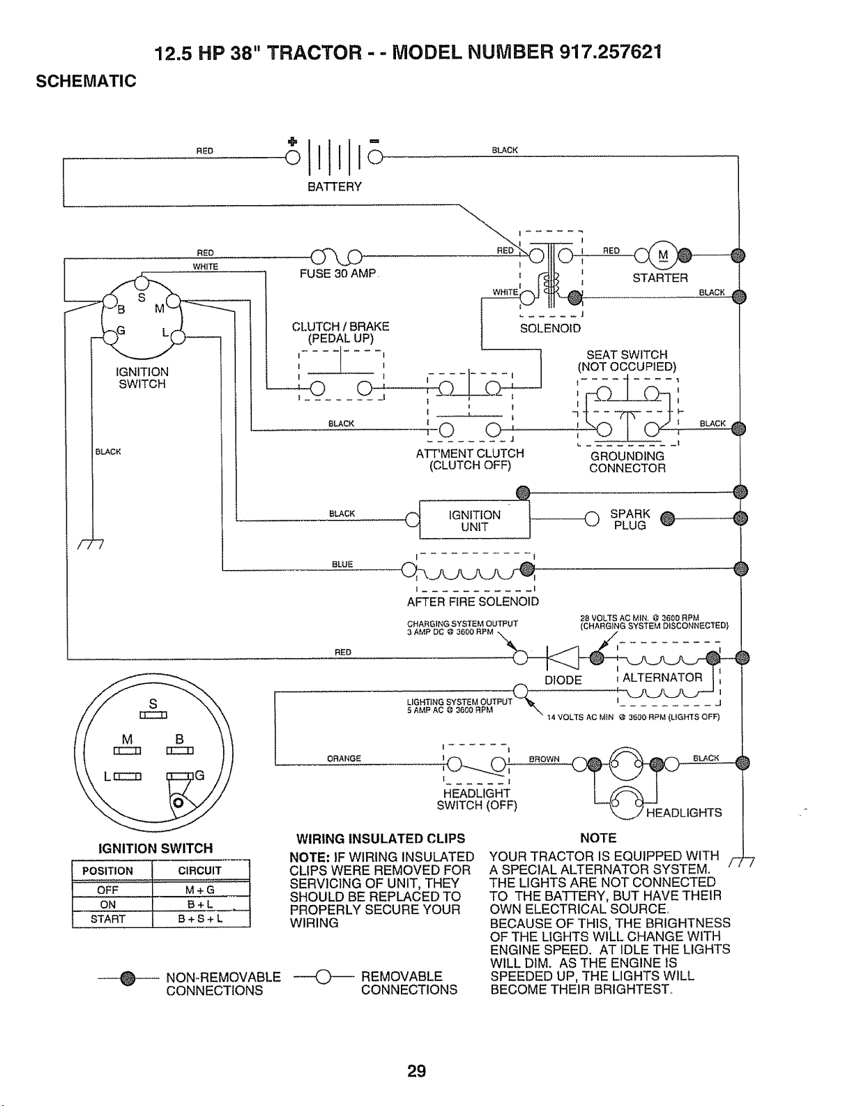
12.5 HP 38" TRACTOR - - MODEL NUMBER 917.257621
SCHEMATIC
BATTERY
RED
WHITE
IGNITION
SWITCH
BLACK
-7
FUSE 30 AMP. _t _!_ I
{ t STARTER
8LACK
..... J
CLUTCH / BRAKE SOLENOID
(PEDAL UP)
I .... l ] SEAT SWITCH
I _ / (NOT OCCUPIED)
I ' I I - 1 | .... J ....
t t I
B_cK _ _ _ , I\r-_ F r'J _ BLACK
......... f
ATT'MENT CLUTCH GROUNDING
(CLUTCH OFF) CONNECTOR
BLACK
JGNmON O SPARK®
UNtT PLUG
BLUE
I I
t ........... I
AFTER FIRE SOLENOID
CHARGING SYSTEM OUTPUT
3 AMP DC @ 3600 RPM
28 VOLTS AC MIN @ 3600 RPM
(CHARGING SYSTEM DISCONNECTED}
RED
I
DIODE 1ALTERNATOR
LIGHTING SYSTEM OUTPUT I j
5 AMP AC @ 3600 RPM "_, .........
t4 VOLTS AC MIN @ 3600 RPM (LIGHTS OFF)
ORANGE 1 I
l
...... |
HEADLIGHT
SWITCH (OFF)
BROWN
IGNITION SWITCH
POSITION CIRCUIT
OFF M + G
ON B+L
START B + S + L
WIRING INSULATED CLIPS
NOTE: IF WIRING INSULATED
CLIPS WERE REMOVED FOR
SERVICING OF UNIT, THEY
SHOULD BE REPLACED TO
PROPERLY SECURE YOUR
WIRING
NON-REMOVABLE ---4_) _ REMOVABLE
CONNECTIONS CONNECTIONS
p
NOTE
YOUR TRACTOR IS EQUIPPED WITH
A SPECIAL ALTERNATOR SYSTEM. f
THE LIGHTS ARE NOT CONNECTED
TO THE BATTERY, BUT HAVE THEIR
OWN ELECTRICAL SOURCE,
BECAUSE OF THIS, THE BRIGHTNESS
OF THE LIGHTS WILL CHANGE WITH
ENGINE SPEED. AT IDLE THE LIGHTS
WILL DIM. AS THE ENGINE IS
SPEEDED UP, THE LIGHTS WILL
BECOME THEIR BRIGHTEST..
29
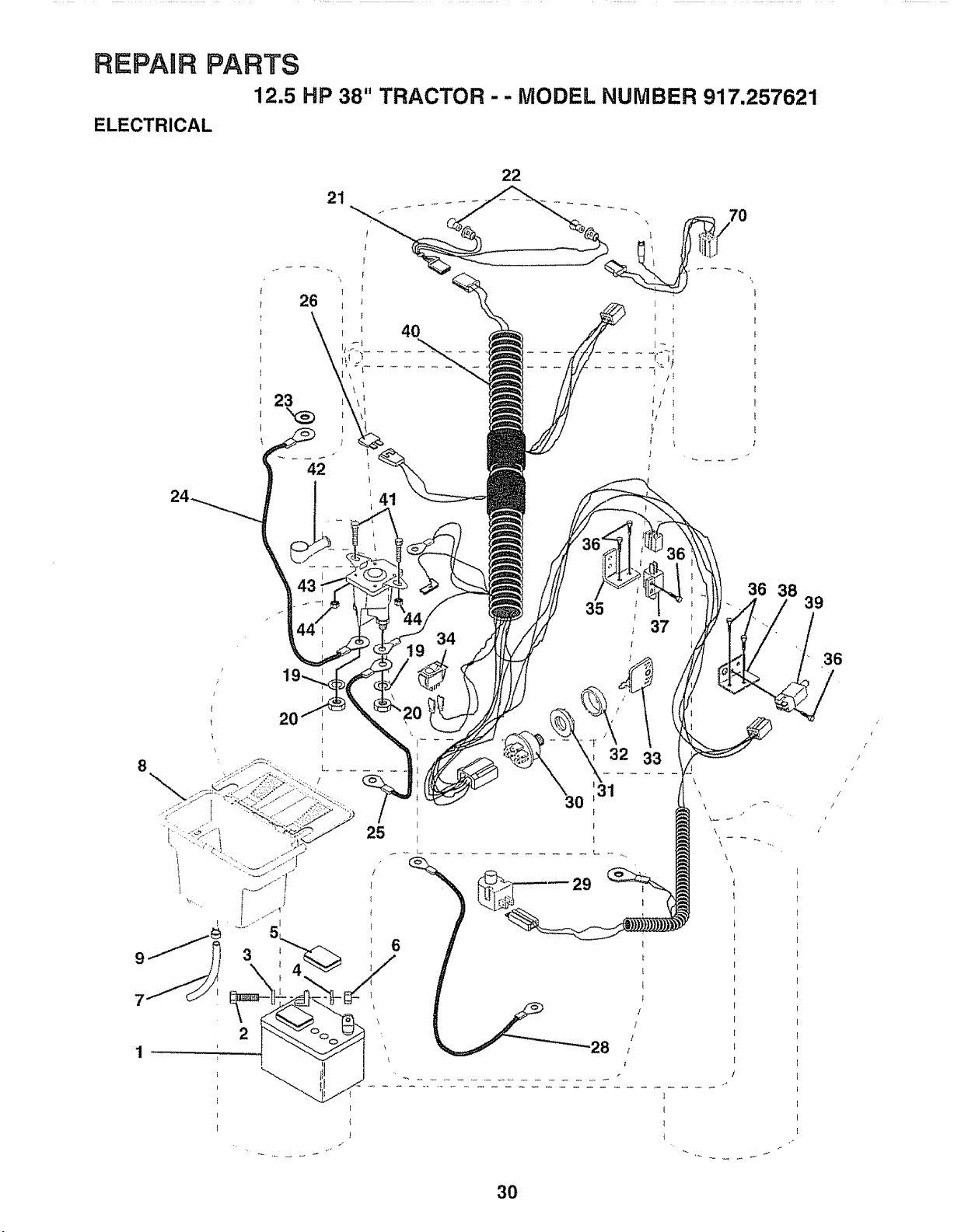
REPAIR PARTS
12.5 HP 38" TRACTOR - - MODEL NUMBER 917.257621
ELECTRICAL
36 38
39
36
r'
I
/
i
!
3O
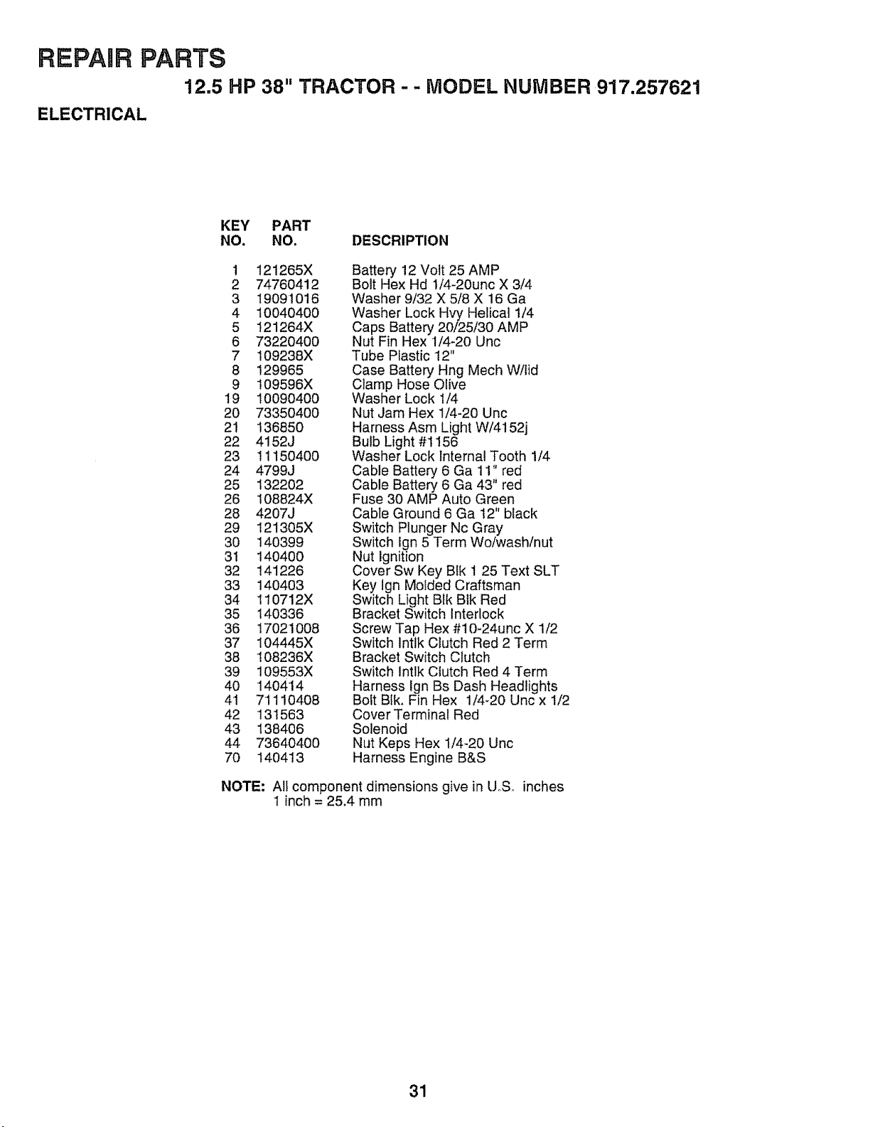
REPAIR PARTS
12.5 HP 38" TRACTOR-- MODEL NUMBER 917.257621
ELECTRICAL
KEY PART
NO. NO. DESCRIPTION
1 121265X
2 74760412
3 19091016
4 10040400
5 t21264X
6 73220400
7 109238X
8 129965
9 109596X
19 10090400
20 73350400
21 136850
22 4152J
23 11150400
24 4799J
25 132202
26 108824X
28 4207J
29 121305X
30 140399
31 140400
32 141226
33 140403
34 110712X
35 140336
36 17021008
37 104445X
38 108236X
39 109553X
40 140414
41 71110408
42 13I563
43 138406
44 73640400
70 140413
Battery 12 Volt 25 AMP
Bolt Hex Hd 1/4-20unc X 3/4
Washer 9/32 X 5/8 X 16 Ga
Washer Lock Hvy Helical 1/4
Caps Battery 20/25/30 AMP
Nut Fin Hex 1/4-20 Unc
Tube Plastic 12"
Case Battery Hng Mech VV/tId
Clamp Hose Olive
Washer Lock 1/4
Nut Jam Hex 1/4-20 Unc
Harness Asm Light W/4152j
Bulb Light #1156
Washer Lock internal Tooth 1/4
Cable Battery 6 Ga 11" red
Cable Batter'_,/6 Ga 43" red
Fuse 30 AMP Auto Green
Cable Ground 6 Ga t2" black
Switch Plunger Nc Gray
Switch Ign 5 Term Wo/wash/nut
Nut Ignition
Cover Sw Key Blk 1 25 Text SLT
Key Ign Molded Craftsman
Switch Light Blk Bik Red
Bracket Switch Interlock
Screw Tap Hex #10-24unc X 1/2
Switch Intlk Clutch Red 2 Term
Bracket Switch Clutch
Switch Intlk Clutch Red 4 Term
Harness Ign Bs Dash Headlights
Bolt Blk. Fin Hex 1/4-20 Unc x 1/2
Cover Terminal Red
Solenoid
Nut Keps Hex I/4-20 Unc
Harness Engine B&S
NOTE: All component dimensions give in U.S. inches
'I inch = 25.4 mm
31
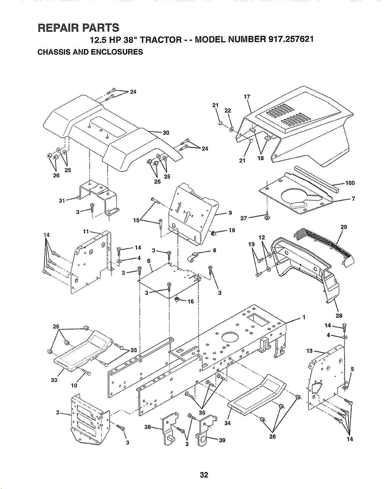
REPAnR PARTS
12.5 HP 38" TRACTOR -- MODEL NUMBER 917,257621
CHASSIS AND ENCLOSURES
17
21 \
22
14
26
21
25
26
18
38 34
39
26
100
7
29
1 28
14-,......
4_.,._
13 _2_,_'J
14
32
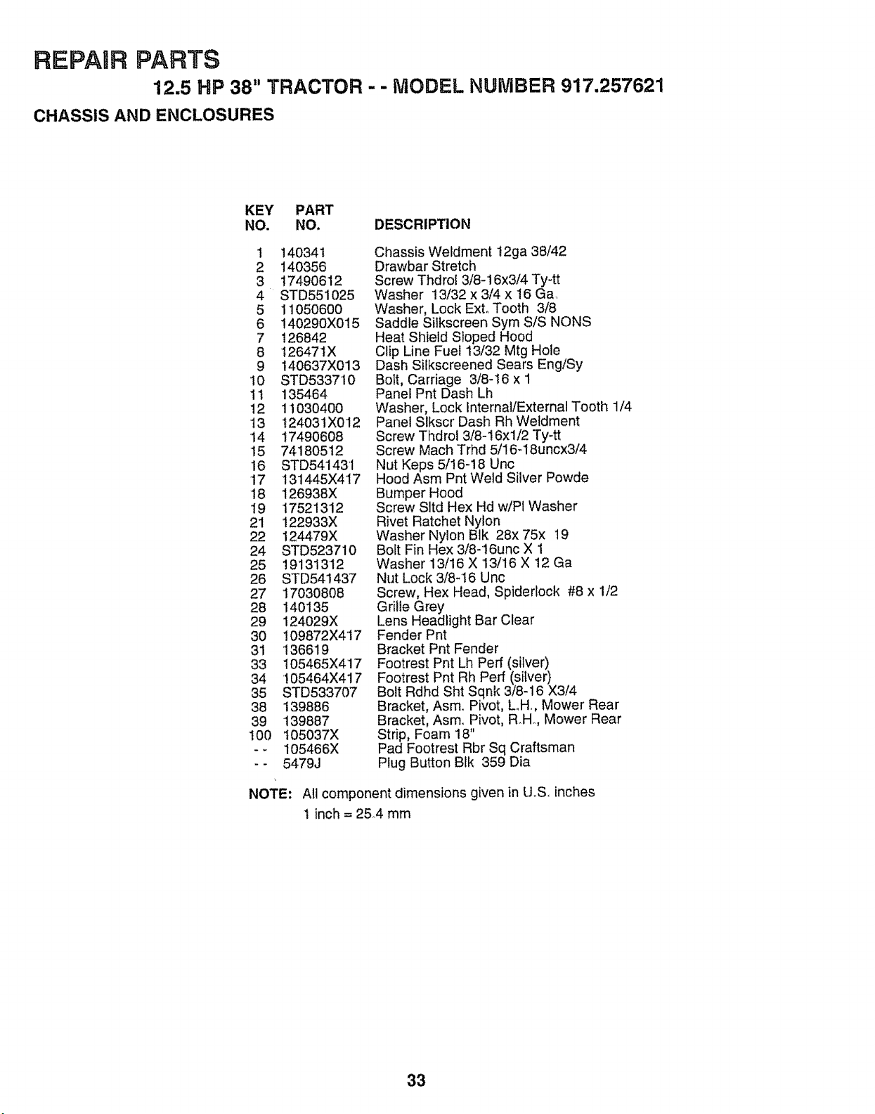
REPAIR PARTS
12.5 HP 38" TRACTOR - - MODEL NUMBER 917.257621
CHASSIS AND ENCLOSURES
KEY PART
NO. NO. DESCRIPTION
1 140341
2 140356
3 1749O612
4 STD551025
5 110506OO
6 140290X015
7 126842
8 t2647tX
9 140637X013
10 STD533710
1t 135464
12 11030400
13 124031XO12
14 1749O608
15 74180512
16 STD541431
17 131445X417
18 126938X
19 17521312
21 122933X
22 124479X
24 STD523710
25 19131312
26 STD541437
27 17030808
28 140135
29 124029X
30 109872X417
31 136619
33 I05465X417
34 !05464X417
35 STD533707
38 139886
39 139887
100 105037X
-- 105466X
-- 5479J
Chassis Weldment 12ga 38/42
Drawbar Stretch
Screw Thdrot 3/8-16x3/4 Ty-tt
Washer 13/32 x 3/4 x 16 Ga.
Washer, Lock ExtoTooth 3/8
Saddle Silkscreen Sym S/S NONS
Heat Shield Sloped Hood
Clip Line Fuel 13/32 Mtg Hole
Dash Silkscreened Sears Eng/Sy
Bolt, Carriage 3/8-16 x 1
Panel Pnt Dash Lh
Washer, Lock Internal/External Tooth 1/4
Panel Slkscr Dash Rh Weldment
Screw Thdrol 3/8-16xl/2 Ty-tt
Screw Mach Trhd 5/16-18uncx3/4
Nut Keps 5/!6-18 Unc
Hood Asm Pnt Wetd Silver Powde
Bumper Hood
Screw Sltd Hex Hd w/Pl Washer
Rivet Ratchet Nylon
Washer Nylon Blk 28x 75x 19
Bolt Fin Hex 3/8-16unc X 1
Washer 13/16 X 13/16 X 12 Ga
Nut Lock 3/8-16 Unc
Screw, Hex Head, Spiderlock #8 x 1/2
Grille Grey
Lens Headlight Bar Clear
Fender Pnt
Bracket Pnt Fender
Footrest Pnt Lh Perf (silver)
Footrest Pnt Rh Perf (silver)
Bolt Rdhd Sht Sqnk 3/8-16 X3/4
Bracket, Asm.. Pivot, Loll., Mower Rear
Bracket, Asm.. Pivot, R.Ho, Mower Rear
Strip, Foam 18"
Pad Footrest Rbr Sq Craftsman
Plug Button BIk 359 Dia
NOTE: All component dimensions given in UoS. inches
1 inch = 25.4 mm
33
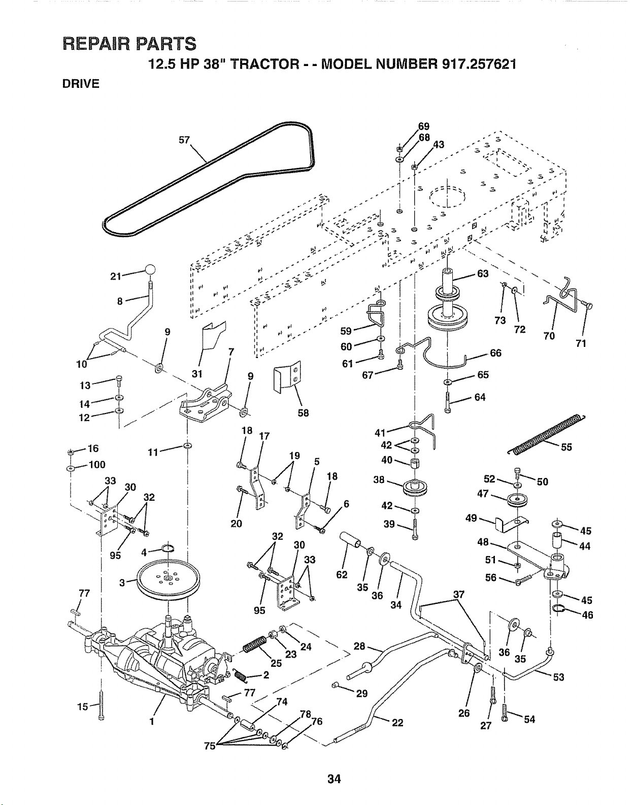
REPARRPARTS
12.5 HP 38" TRACTOR - - MODEL NUMBER 917.257621
DRIVE
57
17
19
5
/
1
77
22
71
34

REPARR
DRIVE
PARTS
12.5 HP 38" TRACTOR - - MODEL NUMBER 917.257621
KEY PART
NO. NO,
142602
2 110422X
3 123666X
4 12000O28
5 121520X
6 17490512
7 130802
8 131679
9 19151216
10 STD561210
11 105701X
12 19091210
13 71040412
14 STD551125
15 74780544
16 STD541431
17 121520X
I8 STD523710
19 STD541437
20 17490512
21 106933X
22 130804
23 STD541437
24 STD541237
25 106888X
26 STD551037
27 STD561210
28 140448
29 124236X
30 130807
31 '127275X
32 STD523107
33 STD541431
34 122424X
35 120183X
36 STD551062
37 STD571810
38 123674X
39 STD523727
40 4470J
41 109070X
KEY PART
DESCRIPTION NO. NO. DESCRIPTION
Transaxle 5sp Std Dana,
Model No, 4360-79
Spring Return Brake T/a Zinc
Pulley Transaxle AkJm
Ring Retainer # 5100-62
Strap Pnt Torque 30 Deg Blk
Screw Thdrol 5/!6-18 X 3/4 Tyt
Plate Pnt Rod Shift T/a (blk)
Rod Shifter BIk (dana)
Washer 15/32 X 3/4 X 16ga
Pin Cotter 1/8 X 1 Cad
Washer Plate Shf 388 Sq Hole
Washer 9/32 X 3/4 X 10 Ga
Bolt Fin Hex 1i4-28unfx3/4 Gr8
Washer Lock Hvy Helical 1/4
Bolt Fin Hex 5/16-18unc X 2-3/4
Nut Lock 5/16-18 Unc
Strap Pnt Torque 30 Deg Blk
Bolt Fin Hex 3/8-16unc X 1
Nut Lock 3/8q 6 Unc
Screw Thdrot 5/16-18 X 3/4 Tyt
Knob Rd 1/2-13 Plstc Thds Blk
Rod Brake Lt
Nut Lock Hex W/wsh 3/8-16unc
Nut Hex Jam 3/8-16 Unc
Spring Rod Brake 2 00 Zinc
Washer 13/32 X t3/16 X 16 Ga
Pin Cotter 1/8 X 3/4 Cad
Rod Brake Parking Lt
Cap Parking Brake Red
Bracket Transmission
Keeper Belt Lh Lt 14 Ga
Bolt Fin Hex 3/8-16unc X 3/4
Nut Lock 5/16-18 Unc
Shaft Asm Pedal Foot 1 930
Bearing Nylon Blk 629 ld
Washer 21/32 X 1 X 16 Ga
Pin Roll 3/16 X 1"
Pulley Idler Fiat
Bolt Fin Hex 3/8-16unc X 2-3/4
Spacer Split 395 X 59 Bzp
Keeper Belt Retainer
42 19131312
43 STD541437
44 105706X
45 110812X
46 12000039
47 127783
48 123789X
49 123205X
50 STD523715
51 STD541437
52 STD551037
53 105710X
54 STD561210
55 105709X
56 STD561210
57 130801
58 127274X
59 140312
60 19131312
61 17490612
62 8883R
63 140186
64 71170764
65 STD551143
66 129921
67 STD523710
68 19131312
69 STD541437
70 134683
71 STD523710
72 19132012
73 STD541437
74 109502X
75 121749X
76 STD581075
77 123583X
78 121748X
95 17490612
100 19111216
Washer 13/32 X 13/16 X 12 Ga
Nut Crownlock 3/8-16 Unc
Bearing Nyl 503 X 628 X 1 25
Washer Hardened
Ring Ktip #t5304-50
Pulley Idler V Groove Plastic
Bellcrank Asm
Retainer Belt Style Spring
Bolt Hex Hd 3/8-16unc X 1-1/2
Nut Crownlock 3/8-16 Unc
Washer 13/32 X 13/16 X 16 Ga
Link Clutch 7 66
Pin Cotter 1/8 X 3/4 Cad
Spring Return Clutch 6 75
Pin Cotter 1/8 X 3/4 Cad
V-belt Ground Drive 95,,25
Keeper Belt Rh Lt Pnt/zinc 16g
Retainer Belt Chassis Lh Zinc
Washer 13/32 X 13/16 X 12 Ga
Screw Thdrot 3/8q 6x3/4 Ty-tt
Cover Pedal BIk Std
Pulley Engine
Bolt Finhex 7/16-20 x 4 g5
Washer Lock Hvy Hlcl Spr 7/16
Keeper Belt Engine Lh Lt
Bolt Fin Hex 3/8-16unc X 1
Washer 13/32 X 13/16 X 12 Ga
Nut Crownlock 3/8-16 Uric
Guide Belt Dr Mower Rh
Bolt Fin Hex 3/8-16unc X 1
Washer 13/32 X 1-1/4 X 12 Ga
Nut Crownlock 3/8-16 Unc
Spacer Split .80xl.94
Washer 25/32 X 1 1/4 X 16 Ga
Ring E #5133-75
Key Square 2 0 X 1845/t865
Washer 25/32 X 1 5/8 X 16ga
Screw Thdrol 3/8-16 x 3/4 Ty Tt
Washer 11/32 x 3/4 x 16 Gao
NOTE: All component dimensions given in US, inches
1 inch = 2&4 mm
35
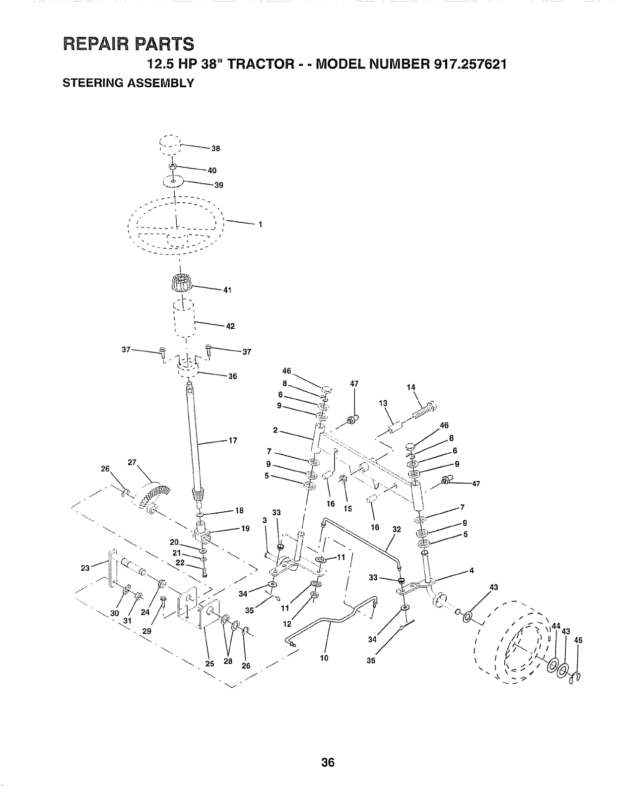
REPAIR PARTS
12.5 HP 38" TRACTOR - - MODEL NUMBER 917.257621
STEERING ASSEMBLY
t
t
17
27
46
33 /
25 26
47 14
\
13 \ j_,
k
16 32
34
35
46
36

REPAUR PARTS
12.5 HP 38" TRACTOR - - MODEL NUMBER 917.257621
STEERING ASSEMBLY
KEY PART
NO. NO, DESCRIPTION
1 139768
2 142033
3 135227
4 135228
5 6266H
6 t21748X
7 19272016
8 '12000029
9 3366R
10 130468
11 STD551137
12 73610600
13 110438X
14 74O11056
15 73901000
16 132624
17 132614
18 57079
19 124035X
20 126684X
21 STD551125
22 71070410
23 127501
24 109816X
25 124036X
26 12000029
27 136874
28 6266H
29 17490612
30 STD551137
31 73610600
32 130465
33 126847X
34 1913!416
35 STD561210
36 132196
37 STD611005
38 139769
39 19133808
40 STD541537
41 104820X
42 124417X
43 121749X
44 121748X
45 12000029
46 121232X
47 6855M
Wheel Steering Std Black
Axle Asm Front
Spindle Asm Lh
Spindle Asm Rh
Bearing Race Thrust Harden
Washer 25/32 X 1 5/8 X 16ga
Washer 27/32 X 1 1/4 X 16 Ga
Ring Klip #t5304-75
Bearing Col Strg BIk
Link Drag Sol Ball Jt 20 064
Washer Lock Hvy Hlcl Spr 3/8
Nut Fin Hex 3/8-24 Unf
Spacer Bearing Axle Front
Bolt Hex 5/8-I1 Unc X 3-1/2
Locknut Flange 5/8-11 Unc
Pin Axle 5/8 X 1 55/1 54 Lg
Shaft Asm Strg 5/8 X 15 19 Lt
Washer Thrust 515x 750x 033
Support Shaft
Washer Shim 1/4 X 5/8 X 062
Washer Lock Hvy Helical 1/4
Screw Hex Socket 1/4-20 X 5/8
Shaft Asm Pittman
Nyfiner Snap in
Bracket Steering
Ring Klip #t5304-75
Gear Sector
Bearing Race Thrust Harden
Screw Thdrol 3/8-16x3/4 Ty4t
Washer Lock Hvy Hlcl Spr 3/8
Nut Fin Hex 3/8-24 Unf
Rod Tie Wire Form 19 75 Mech
Bushing Rod Tie Blk Lt
Washer 13/32 X 7/8 X 16ga
Pin Cotter 1/8 X 3/4 Cad
Bushing Strg 5/8 Id Dash
Screw Slftp #t0-16 X 1/2 Ty-b
Insert Cap Strg Wheel Std BIk
Washer 13/32 X 2-3/8 X 8 Ga
Nut Lock Center 3/8-24unf
Adaptor Wheel Strg 640/635id
Boot Shaft Steering
Washer 25/32 X 1 1/4 X 16 Ga
Washer 25/32 X 1 5/8 X 16ga
Ring Klip #t5304-75
Cap Spindle Fr Top BIk
Fitting Grease
NOTE: All component dimensions given in U,So inches
1 inch = 25°4 mm
37
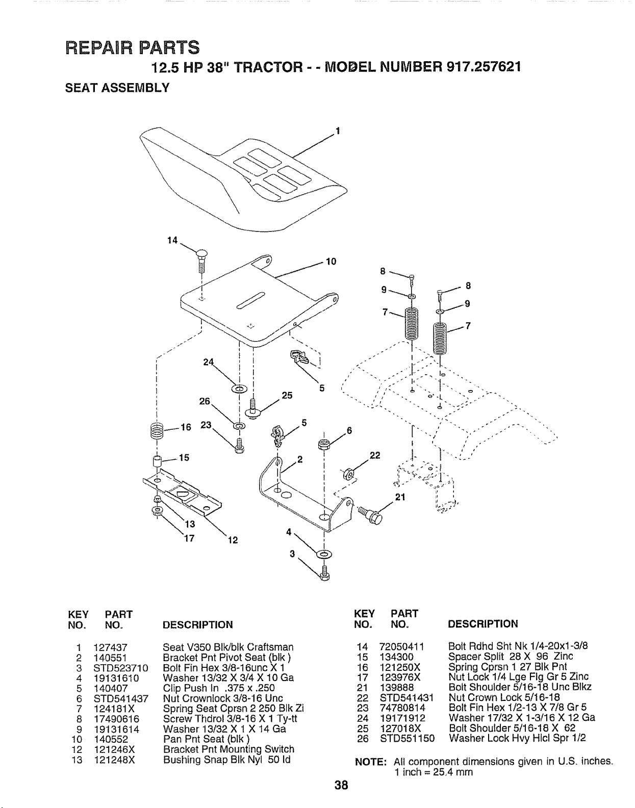
REPAUR PARTS
12.5 HP 38" TRACTOR - - MODEL NUMBER 917.257621
SEAT ASSEMBLY
10
KEY
NO.
1
2
3
4
5
6
7
8
9
10
12
13
PART
NO.
127437
14055 I
STD523710
19131610
140407
STD54t 437
124181X
17490616
19131614
140552
121246X
121248X
KEY PART
DESCRIPTION NO. NO. DESCRIPTION
Seat V350 BIk/blk Craftsman
Bracket Pnt Pivot Seat (blk)
Bolt Fin Hex 3/8-16unc X 1
Washer 13/32 X 3/4 X 10 Ga
Clip Push In .375 x .250
Nut Crownlock 3/8-16 Unc
Spring Seat Cprsn 2 250 BIk Zi
Screw Thdrol 3/8-16 X 1 Ty-tt
Washer 13/32 X 1 X 14 Ga
Pan Pnt Seat (blk)
Bracket Pnt Mounting Switch
Bushing Snap BIk Nyl 50 Id
38
I4 72050411
15 1343OO
16 121250X
17 123976X
21 139888
22 STD541431
23 74780814
24 19171912
25 127018X
26 STD551150
Bolt Rdhd Sht Nk 1/4-20xl-3/8
Spacer Split 28 X 96 Zinc
Spring Cprsn 1 27 BIk Pnt
Nut Lock 1/4 Lge Fig Gr 5 Zinc
Boft Shoulder 5/16-18 Unc Blkz
Nut Crown Lock 5/16-18
Bolt Fin Hex 1/2-13 X 7/8 Gr5
Washer 17/32 X 1-3/16 X 12 Ga
Bolt Shoulder 5/16-18 X 62
Washer Lock Hvy Hicl Spr 1/2
NOTE: AIt component dimensions given in U,S, inches,
1 inch = 25°4 mm
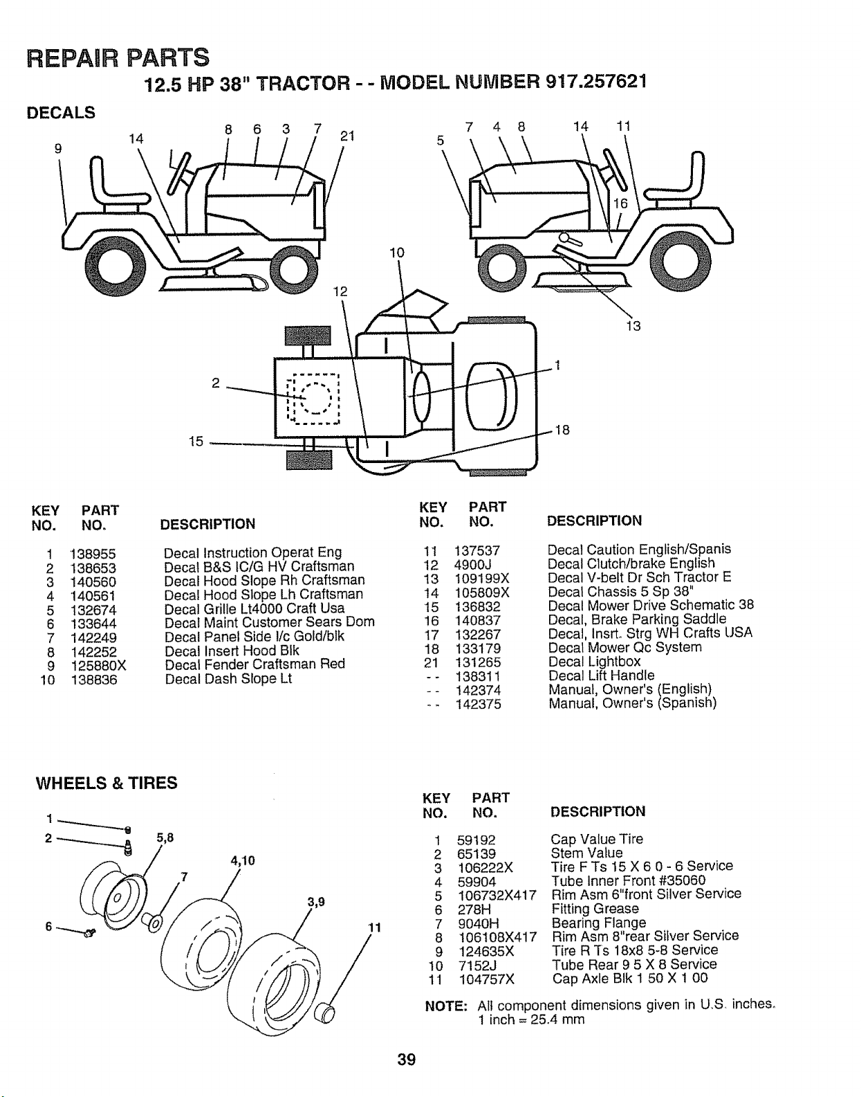
REPAIR
DECALS
9
PARTS
12.5 HP 38" TRACTOR -- MODEL NUMBER 917.257621
8 6 3 7 7 4 8 14 11
14 21 _\
10
t5
18
13
KEY PART
NO. NO.
1 "138955
2 138653
3 140560
4 '140561
5 132674
6 133644
7 142249
8 142252
9 125880X
10 138836
KEY PART
DESCRIPTION NO. NO. DESCRIPTION
Decal Instruction Operat Eng 11
Decal B&S tC/G HV Craftsman 12
Decal Hood Slope Rh Craftsman 13
Decal Hood Slope Lh Craftsman 14
Decal Grille Lt4000 Craft Usa 15
Decal Maint Customer Sears Dom 16
Decal Panel Side i!c Gold/blk 17
Decal Insert Hood BIk 18
Decal Fender Craftsman Red 21
Decal Dash Slope Lt - -
137537
4900J
I09199X
105809X
136832
140837
132267
133179
131265
138311
142374
142375
Deca! Caution English/Spanis
Decal Clutch/brake English
Decal V-belt Dr Sch Tractor E
Decal Chassis 5 Sp 38"
Decal Mower Drive Schematic 38
Decal, Brake Parking Saddle
Decal, lnsrL Strg WH Crafts USA
Decal Mower Qc System
Decal Lightbox
Decal Lift Handle
Manual, Owner's (English)
Manual, Owner's (Spanish)
WHEELS & TIRES
5,8
7
4;10
11
KEY PART
NO. NO. DESCRIPTION
1 59192
2 65139
3 106222X
4 59904
5 106732X417
6 278H
7 9040H
8 106t08X417
9 124635X
10 7152J
11 104757X
NOTE:
Cap Value Tire
Stem Value
Tire F Ts 15 X 6 0 - 6 Service
Tube Inner Front #35060
Rim Asm 6"front Silver Service
Fitting Grease
Bearing Flange
Rim Asm 8 rear Silver Service
Tire R Ts 18x8 5-8 Service
Tube Rear 9 5 X 8 Service
Cap Axle BIk 1 50 X ! 00
All component dimensions given in U,.S. inches_
1 inch = 25°4 mm
39
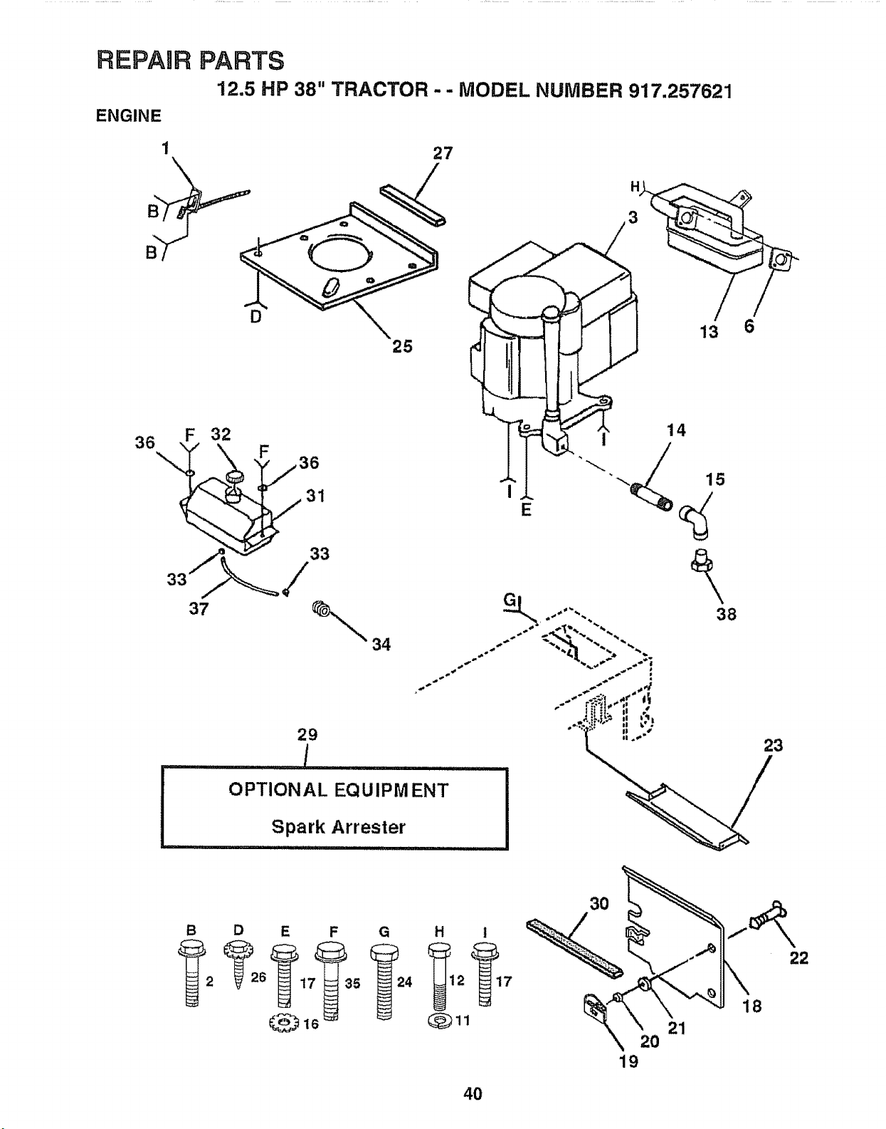
REPAUR PARTS
12.5 HP 38" TRACTOR -- MODEL NUMBER 917.257621
ENGINE
1
D
36 F 32
33___/1
33
37 _
25
34
27
29
l ......................
OPTIONAL EQUIPM ENT
Spark Arrester
ll,i................ .......................
23
B D E F G H i
Qll
30
20
19
21
22
18
40
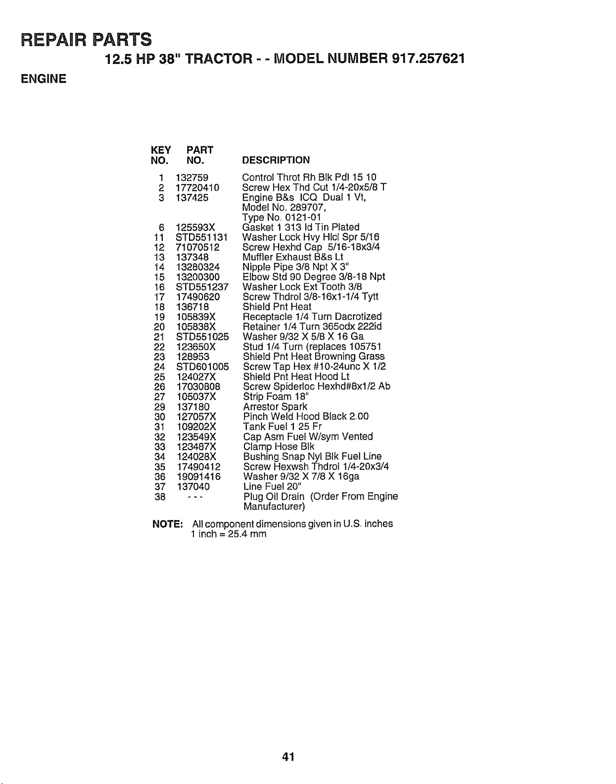
REPAIR PARTS
12.5 HP 38" TRACTOR ..- MODEL NUMBER 917.257621
ENGINE
KEY PART
NO. NO, DESCRIPTION
1 132759
2 17720410
3 137425
6 125593X
tl STD551131
12 71070512
13 137348
14 13280324
15 13200300
16 STD55!237
17 17490620
!8 136718
19 105839X
20 105838X
21 STD551025
22 123650X
23 128953
24 STD601005
25 124027X
26 17030808
27 105037X
29 137180
30 127057X
31 109202X
32 123549X
33 t23487X
34 t24028X
35 17490412
36 19091416
37 137040
38 o--
Control Throt Rh Blk Pd115 10
Screw Hex Thd Cut 1/4-20x5/8 T
Engine B&s ICQ Dual 1 Vt,
Model No,, 289707,
Type No, 0121-01
Gasket 1 313 Id Tin Plated
Washer Lock Hvy Hlcl Spr 5/I6
Screw Hexhd Cap 5/16-18x3/4
Muffler Exhaust B&s Lt
Nipple Pipe 3/8 Npt X 3"
Elbow Std 90 Degree 3/8-18 Npt
Washer Lock Ext Tooth 3/8
Screw Thdrol 3/8-16x14/4 Tytt
Shield Pnt Heat
Receptacle !/4 Turn Dacrotized
Retainer 1/4 Turn 365odx 222id
Washer 9/32 X 5/8 X 16 Ga
Stud 1/4 Turn (replaces 105751
Shield Pnt Heat Browning Grass
Screw Tap Hex #10-24unc X 1/2
Shield Pnt Heat Hood Lt
Screw Spidertoc Hexhd#8xl/2 Ab
Strip Foam 18"
Arrestor Spark
Pinch Weld Hood Black 2.00
Tank Fuel 1 25 Fr
Cap Asm Fuel W/sym Vented
Clamp Hose BIk
Bushing Snap Nyl BIk Fuel Line
Screw Hexwsh Thdrol 1/4-20x3/4
Washer 9/32 X 7/8 X 16ga
Line Fuel 20"
Plug Oil Drain (Order From Engine
Manufacturer)
NOTE: All component dimensions given in U.S. inches
1 inch = 25.4 mm
41
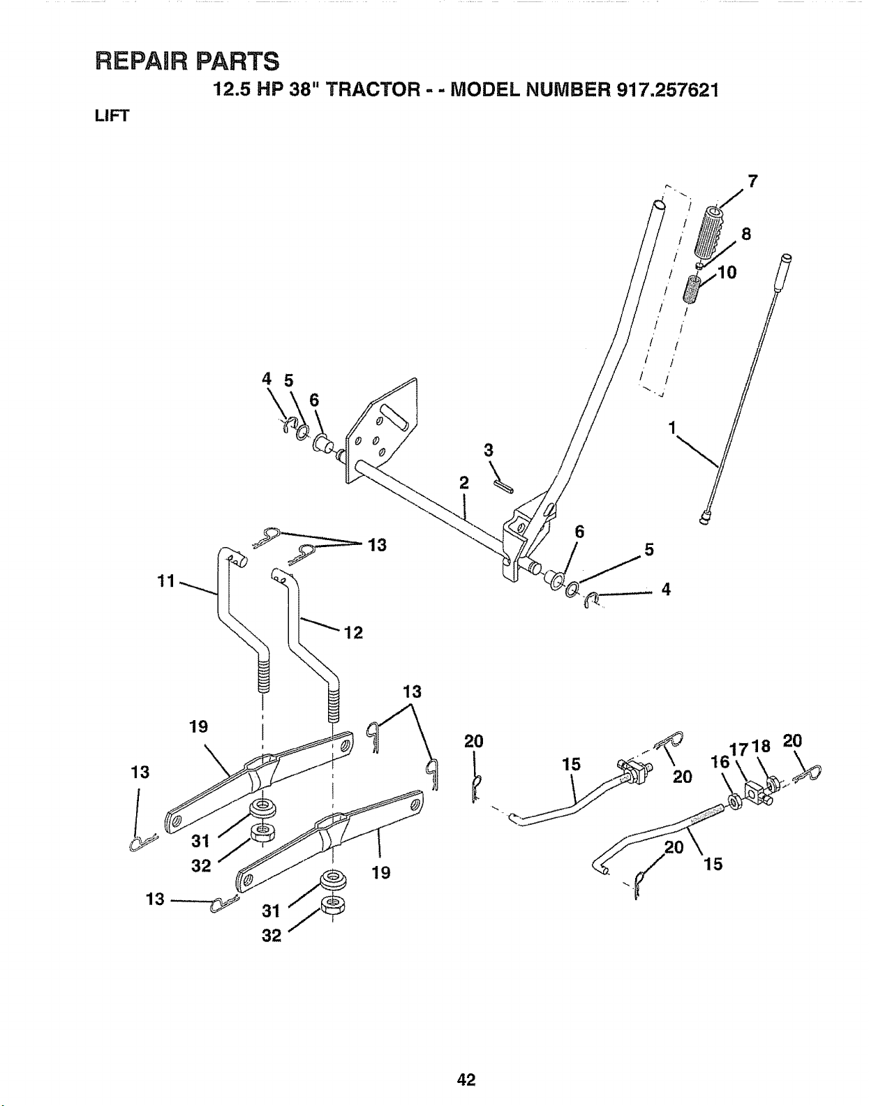
REPAIR PARTS
12.5 HP 38" TRACTOR - - MODEL NUMBER 917.257621
LIFT
4 5
6
12
2
3
\
6
8
5
19
13
32
1
1
1
I
i
32
19
13
20 F_
15 20
161718 20
15
42
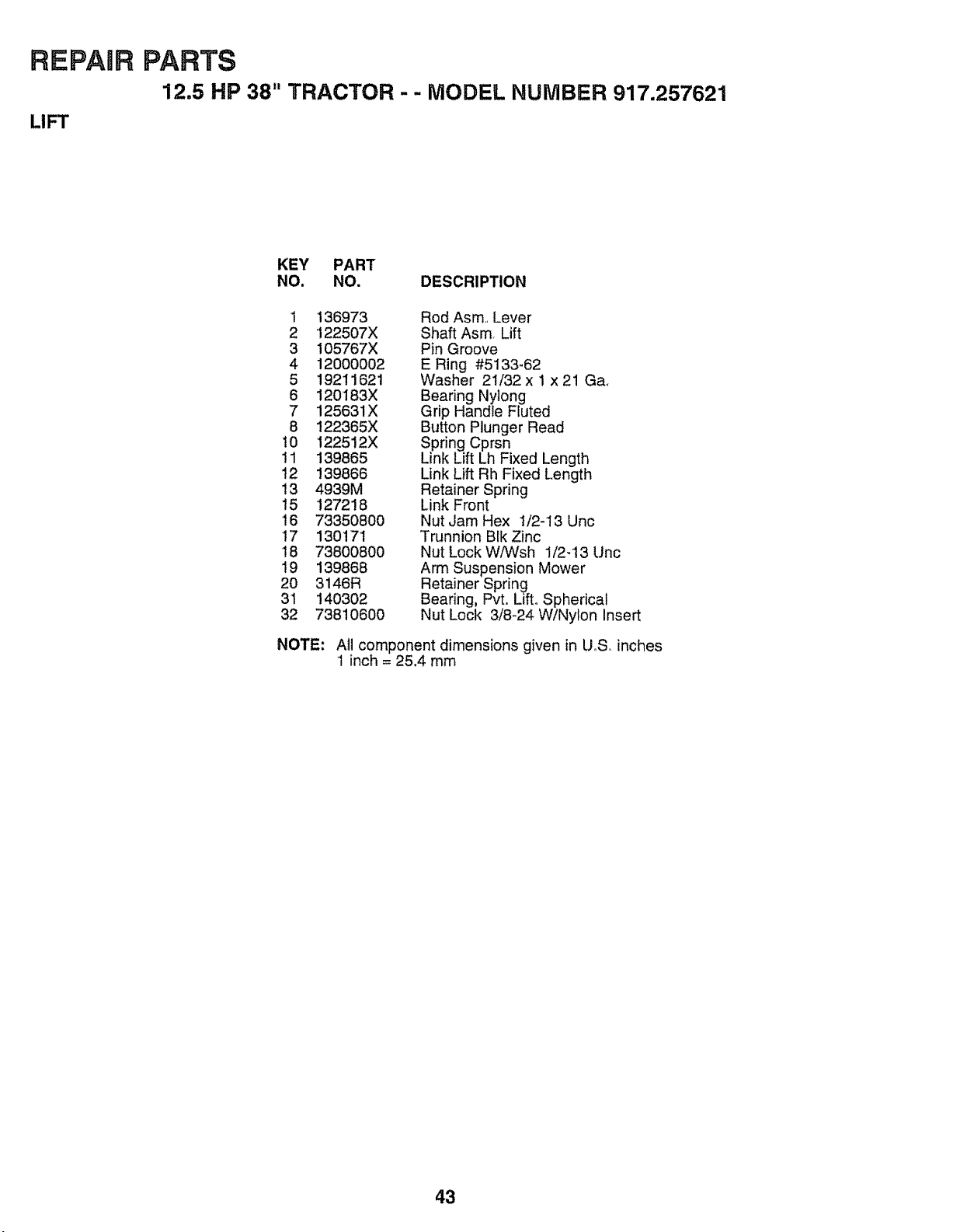
REPAHR
LIFT
PARTS
12.5 HP 38" TRACTOR - - MODEL NUMBER 917.257621
KEY PART
NO. NO. DESCRIPTION
1 136973
2 122507X
3 105767X
4 120000O2
5 19211621
6 120183X
7 125631X
8 122365X
t0 122512X
11 139865
12 139866
t3 4939M
!5 127218
16 73350800
17 130171
18 73800800
!9 139868
20 3146R
31 140302
32 73810600
Rod Asm, Lever
Shaft Asm, Lift
Pin Groove
E Ring #5133-62
Washer 21/32 x 1 x 21 Ga.
Bearing Nylong
Grip Handle Fluted
Button Plunger Read
Spring Cprsn
Link Lift Lh Fixed Length
Link Lift Rh Fixed Length
Retainer Spring
Link Front
Nut Jam Hex 1/2-13 Unc
Trunnion Blk Zinc
Nut Lock WiWsh 1/2-13 Unc
Arm Suspension Mower
Retainer Spring
Bearing, Pvt. Lift° Spherical
Nut Lock 3/8-24 W/Nylon Insert
NOTE: All component dimensions given in U,S inches
1 inch = 25.4 mm
43
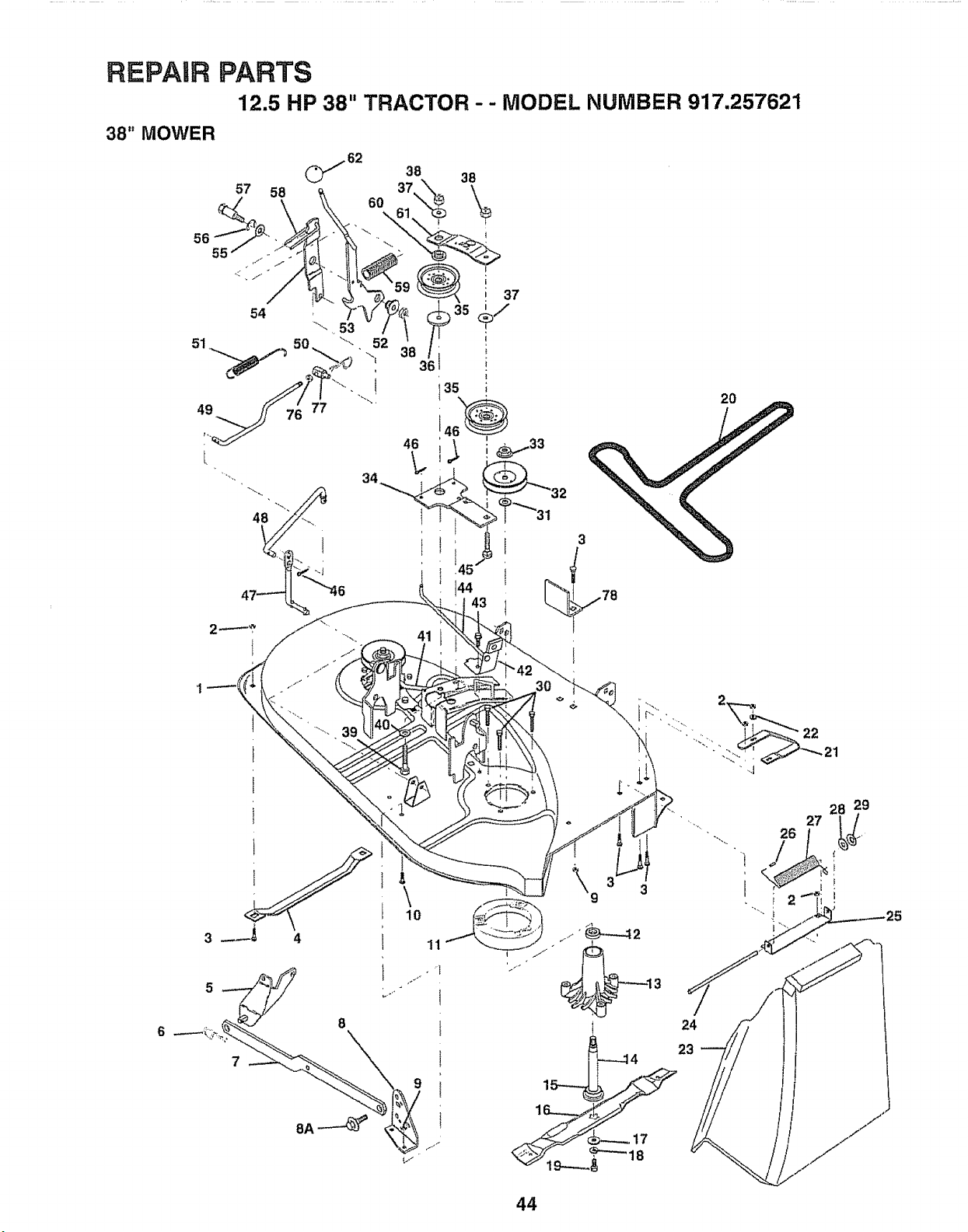
REPAIR PARTS
12.5 HP 38" TRACTOR - - MODEL NUMBER 917.257621
38" MOWER
38
57 58
56
55
54 _-. 53
49 77
2O
6
5
7
\
10
11
24
23
44
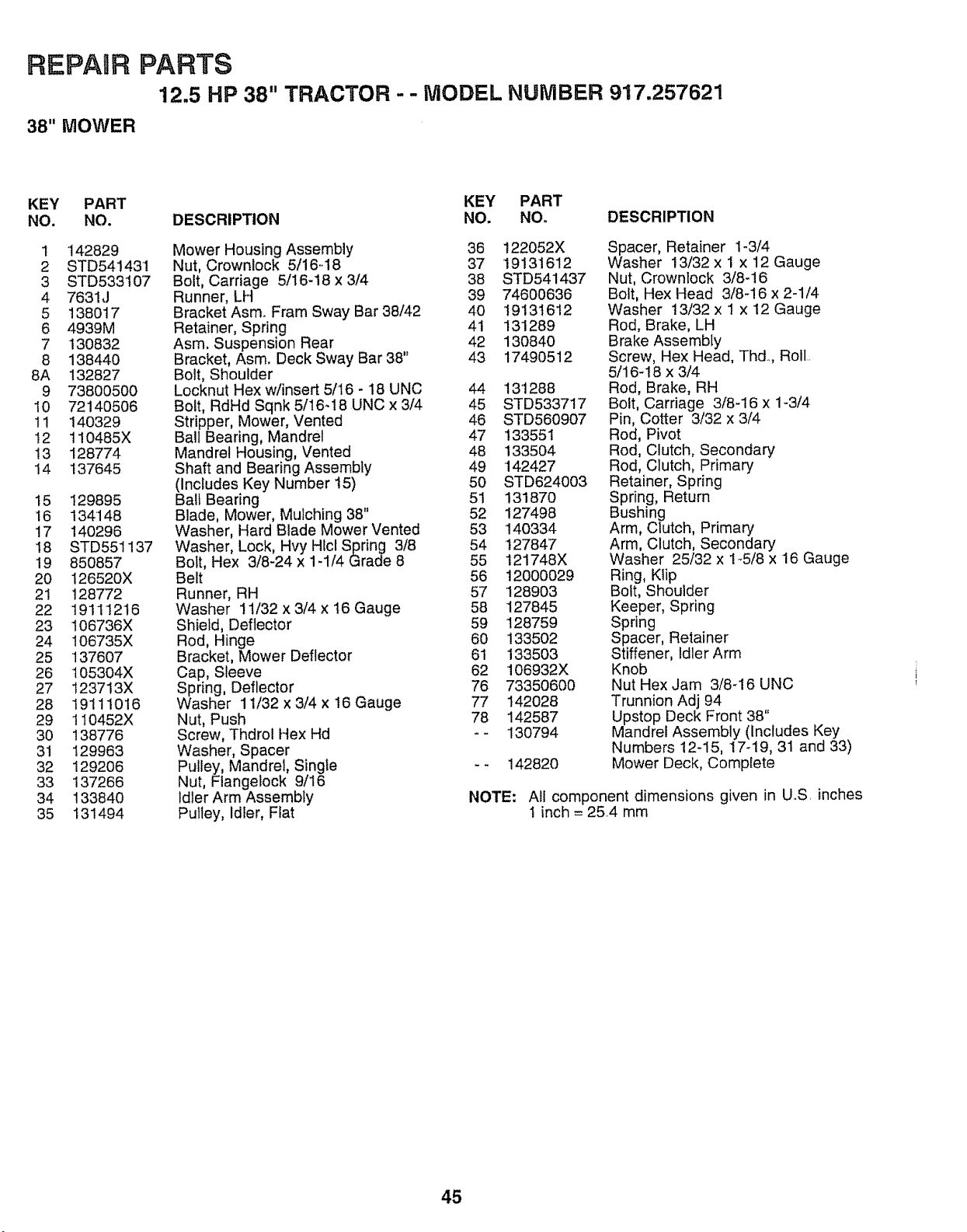
REPAUR PARTS
12.5 HP 38" TRACTOR -- MODEL NUMBER 917.257621
38" MOWER
KEY PART KEY PART
NO. NO. DESCRIPTION NO. NO. DESCRIPTION
1 "142829
2 STD541431
3 STD533t07
4 7631J
5 138017
6 4939M
7 130832
8 138440
8A 132827
9 73800500
10 72140506
11 140329
12 110485X
13 128774
14 137645
15 129895
16 134148
17 140296
!8 STD551137
19 850857
20 126520X
21 128772
22 19111216
23 106736X
24 106735X
25 137607
26 105304X
27 123713X
28 19111016
29 110452X
30 138776
31 129963
32 129206
33 137266
34 133840
35 131494
Mower Housing Assembly 36
Nut, Crownlock 5/16..18 37
Bolt, Carriage 5/16-18 x 3/4 38
Runner, LH 39
Bracket Asm. Fram Sway Bar 38/42 40
Retainer, Spring 41
Asm. Suspension Rear 42
Bracket, Asm. Deck Sway Bar 38" 43
Bolt, Shoulder
Locknut Hex w/insert 5/16 - 18 UNC 44
Bolt, RdHd Sqnk 5/16-18 UNC x 3/4 45
Stripper, Mower, Vented 46
Ball Bearing, Mandrel 47
Mandrel Housing, Vented 48
Shaft and Bearing Assembly 49
(Includes Key Number t5) 50
Ball Bearing 51
Blade, Mower, Mulching 38" 52
Washer, Hard Blade Mower Vented 53
Washer, Lock, Hvy Hlcl Spring 3/8 54
Bolt, Hex 3/8-24 x 1-1/4 Grade 8 55
Belt 56
Runner, RH 57
Washer 11/32 x 3/4 x 16 Gauge 58
Shield, Deflector 59
Rod, Hinge 60
Bracket, Mower Deflector 61
Cap, Sleeve 62
Spring, Deflector 76
Washer 11/32 x 3/4 x 16 Gauge 77
Nut, Push 78
Screw, Thdrol Hex Hd - -
Washer, Spacer
Pulley, Mandrel, Single - -
Nut, Flangelock 9/16
Idler Arm Assembly
Pulley, Idler, Flat
122052X
19131612
STD541437
74600636
19131612
131289
130840
17490512
13'1288
STD533717
STD560907
133551
133504
142427
STD624003
131870
127498
140334
127847
121748X
12000029
128903
127845
128759
133502
133503
106932X
73350600
142028
142587
130794
142820
Spacer, Retainer 1-3/4
Washer 13/32 x 1 x 12 Gauge
Nut, Crownlock 3/8-16
Bolt, Hex Head 3/8-16 x 2-1/4
Washer 13/32 x 1 x 12 Gauge
Rod, Brake, LH
Brake Assembly
Screw, Hex Head, Thd.., Roll..
5/16-18 x 3/4
Rod, Brake, RH
Bolt, Carriage 3/8-16 x 1-3/4
Pin, Cotter 3/32 x 3/4
Rod, Pivot
Rod, Clutch, Secondary
Rod, Clutch, Primary
Retainer, Spring
Spring, Return
Bushing
Arm, Clutch, Primary
Arm, Clutch, Secondary
Washer 25/32 x 1_5/8 x 16 Gauge
Ring, Klip
Bolt, Shoulder
Keeper, Spring
Spring
Spacer, Retainer
Stiffener, Idler Arm
Knob
Nut Hex Jam 3/8_16 UNC
Trunnion Adj 94
Upstop Deck Front 38"
Mandrel Assembly (Includes Key
Numbers 12-15, 17-19, 31 and 33)
Mower Deck, Complete
NOTE: All component dimensions given in UoS. inches
1 inch = 25.4 mm
45
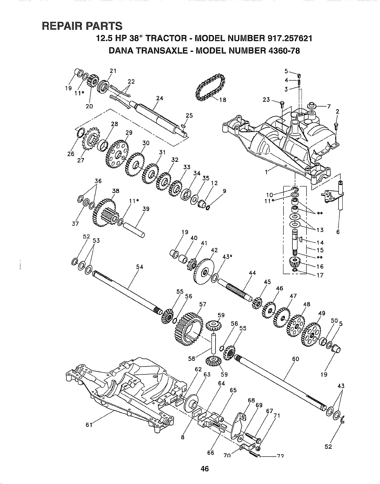
REPAUR PARTS
12.5 HP 38" TRACTOR - MODEL NUMBER 917.257621
DANA TRANSAXLE - MODEL NUMBER 4360-78
21
22
19
11"
24 23
27
37
52
36
55
3B
11'
39
54
31
32
33
34
19
40
55
56
35
!2
9
11
41
42
43*
57
59
iB55
44
45
46
4 _
I
(
1
47
2
F"_I 3 6
I
14
15
I
16
17
48
49
61
62
8
/
66
59
65
68
69
1
60
19
43
52
46
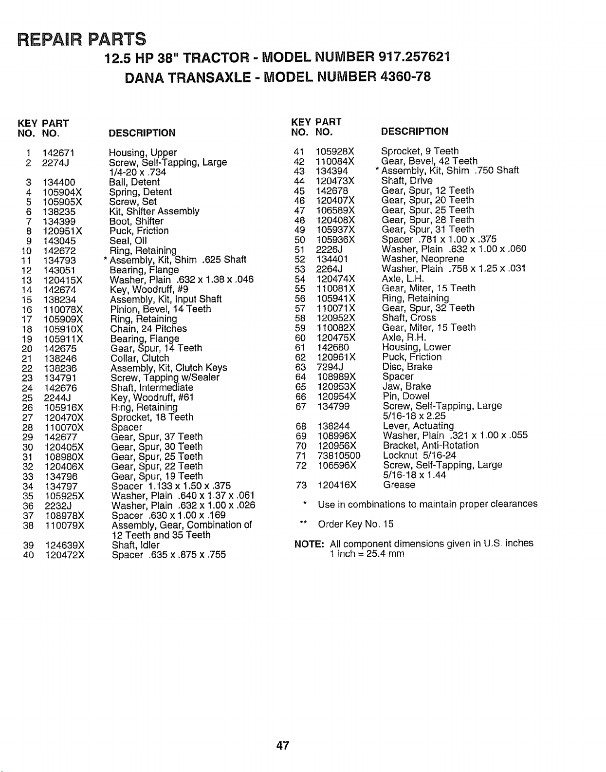
REPAnR PARTS
12.5 HP 38" TRACTOR - MODEL NUMBER 917,257621
DANA TRANSAXLE - MODEL NUMBER 4360-78
KEY PART
NO. NO,
1 142671
2 2274J
3 134400
4 105904X
5 105905X
6 138235
7 134399
8 120951X
9 143045
t0 142672
11 134793
12 143051
13 120415X
14 142674
15 138234
16 110078X
17 105909X
18 105910X
19 105911X
20 142675
21 138246
22 138236
23 134791
24 142676
25 2244J
26 105916X
27 120470X
28 110070X
29 142677
30 120405X
31 108980X
32 120406X
33 134796
34 134797
35 105925X
36 2232J
37 108978X
38 110079X
39 124639X
40 120472X
KEY PART
DESCRIPTION NO. NO. DESCRIPTION
Housing, Upper 41
Screw, Self-Tapping, Large 42
1/4-20 x °734 43
Bali, Detent 44
Spring, Detent 45
Screw, Set 46
Kit, Shifter Assembly 47
Boot, Shifter 48
Puck, Friction 49
Seal, Oil 50
Ring, Retaining 51
Assembly, Kit, Shim .625 Shaft 52
Bearing, Flange 53
Washer, Plain .632 x 1.38 x **046 54
Key, Woodruff, #9 55
Assembly, Kit, Input Shaft 56
Pinion, Bevel, 14 Teeth 57
Ring, Retaining 58
Chain, 24 Pitches 59
Bearing, Flange 60
Gear, Spur, 14 Teeth 6t
Collar, Clutch 62
Assembly, Kit, Clutch Keys 63
Screw, Tapping w/Sealer 64
Shaft, Intermediate 65
Key, Woodruff, #61 66
Ring, Retaining 67
Sprocket, 18 Teeth
Spacer 68
Gear, Spur, 37 Teeth 69
Gear, Spur, 30 Teeth 70
Gear, Spur, 25 Teeth 71
Gear, Spur, 22 Teeth 72
Gear, Spur, 19 Teeth
Spacer 1:133 x 1.50 x .375 73
Washer, Plain .640 x 1.37 x .061
Washer, Plain _632x 1.00 x .026
Spacer .630 x 1.00 x ,169
Assembly, Gear, Combination of
12 Teeth and 35 Teeth
Shaft, Idler
Spacer °635 x .875 x .755
105928X
110084X
134394
120473X
142678
120407X
106589X
120408X
105937X
t05936X
2226J
134401
2264J
120474X
110081X
105941X
1!0071X
120952X
110082X
120475X
142680
120961X
7294J
108989X
120953X
120954X
134799
138244
108996X
120956X
73810500
106596X
120416X
Sprocket, 9 Teeth
Gear, Bevel, 42 Teeth
Assembly, Kit, Shim °750 Shaft
Shaft, Drive
Gear, Spur, 12 Teeth
Gear, Spur, 20 Teeth
Gear, Spur, 25 Teeth
Gear, Spur, 28 Teeth
Gear, Spur, 31 Teeth
Spacer o781 x 1.00 x .375
Washer, Plain ,632 x 1.00 x _060
Washer, Neoprene
Washer, Plain °758 x 1.25 x ..031
Axle, Loll..
Gear, Miter, 15 Teeth
Ring, Retaining
Gear, Spur, 32 Teeth
Shaft, Cross
Gear, Miter, 15 Teeth
Axle, R.H.
Housing, Lower
Puck, Friction
Disc, Brake
Spacer
Jaw, Brake
Pin, Dowel
Screw, Self-Tapping, Large
5/16-18 x 2,.25
Lever, Actuating
Washer, Plain .321 x 1.,00x °055
Bracket, Anti-Rotation
Locknut 5/16-24
Screw, Self-Tapping, Large
5/16-18 x 1,.44
Grease
* Use in combinations to maintain proper clearances
** Order Key No. 15
NOTE: Air component dimensions given in U.S. inches
1 inch = 25.4 mm
47
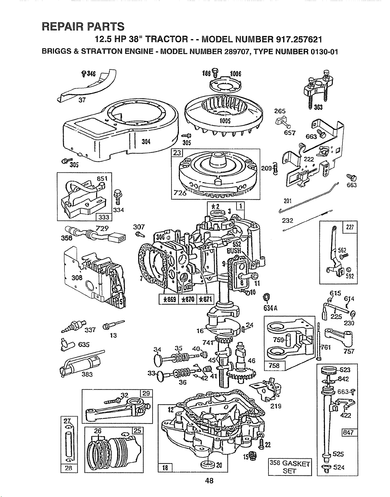
REPAIR PARTS
12.5 HP 38" TRACTOR - - MODEL NUMBER 917.257621
BRIGGS & STRATTON ENGINE - MODEL NUMBER 289707, TYPE NUMBER 0130-01
334
307
265
657
11
634,_
663
21
92
757
!
27
<Z
%.,
<:3
2_
383
26
48
219
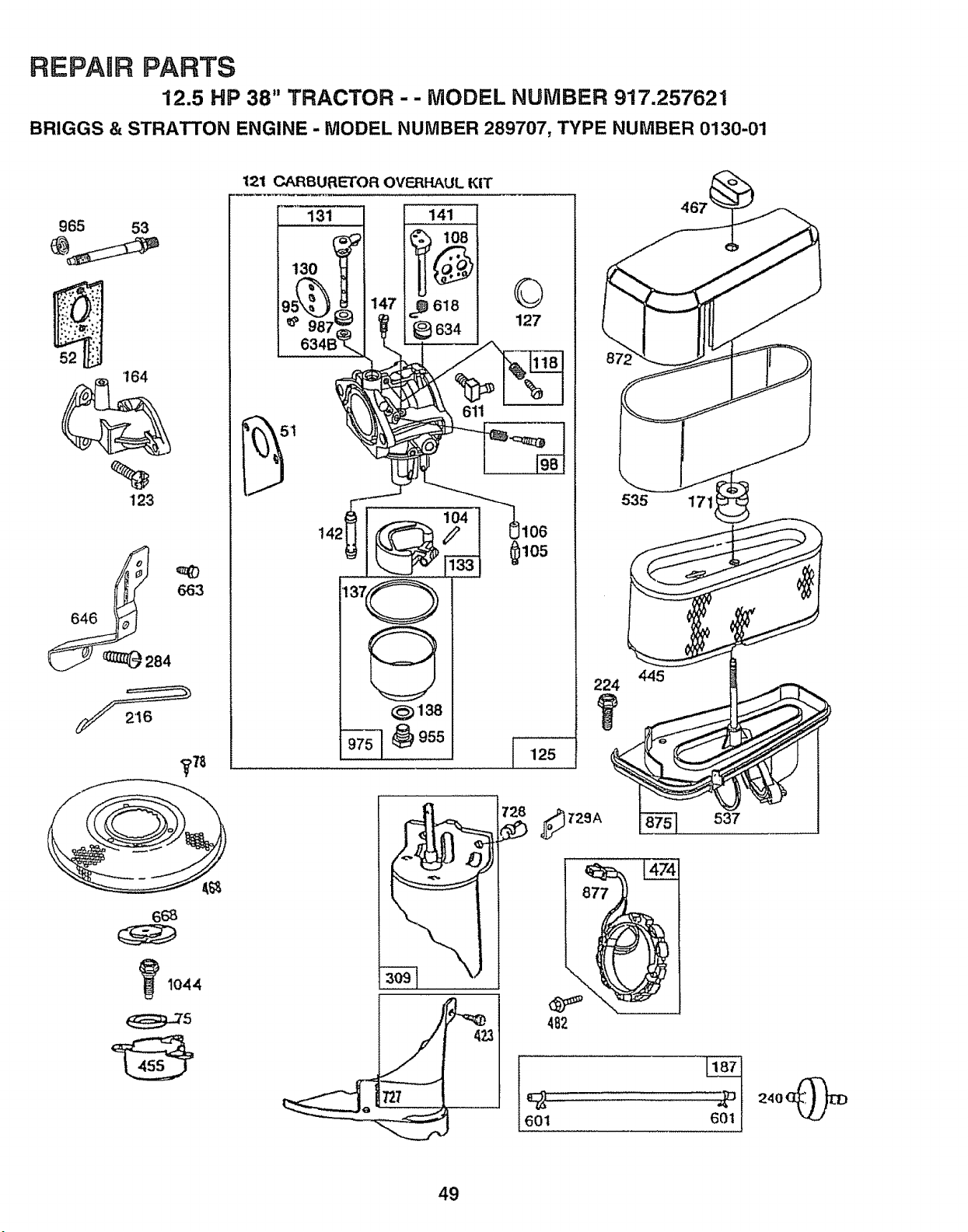
REPAIR PARTS
12.5 HP 38" TRACTOR - - MODEL NUMBER 917.257621
BRIGGS & STRATTON ENGINE - MODEL NUMBER 289707, TYPE NUMBER 0130-01
965 53
'164
%
I23
84
_78
_1044
121 CARBURETOR OVF_,RHAULKIT
131 141
618
634
51
©
127
445
224
601
537
49
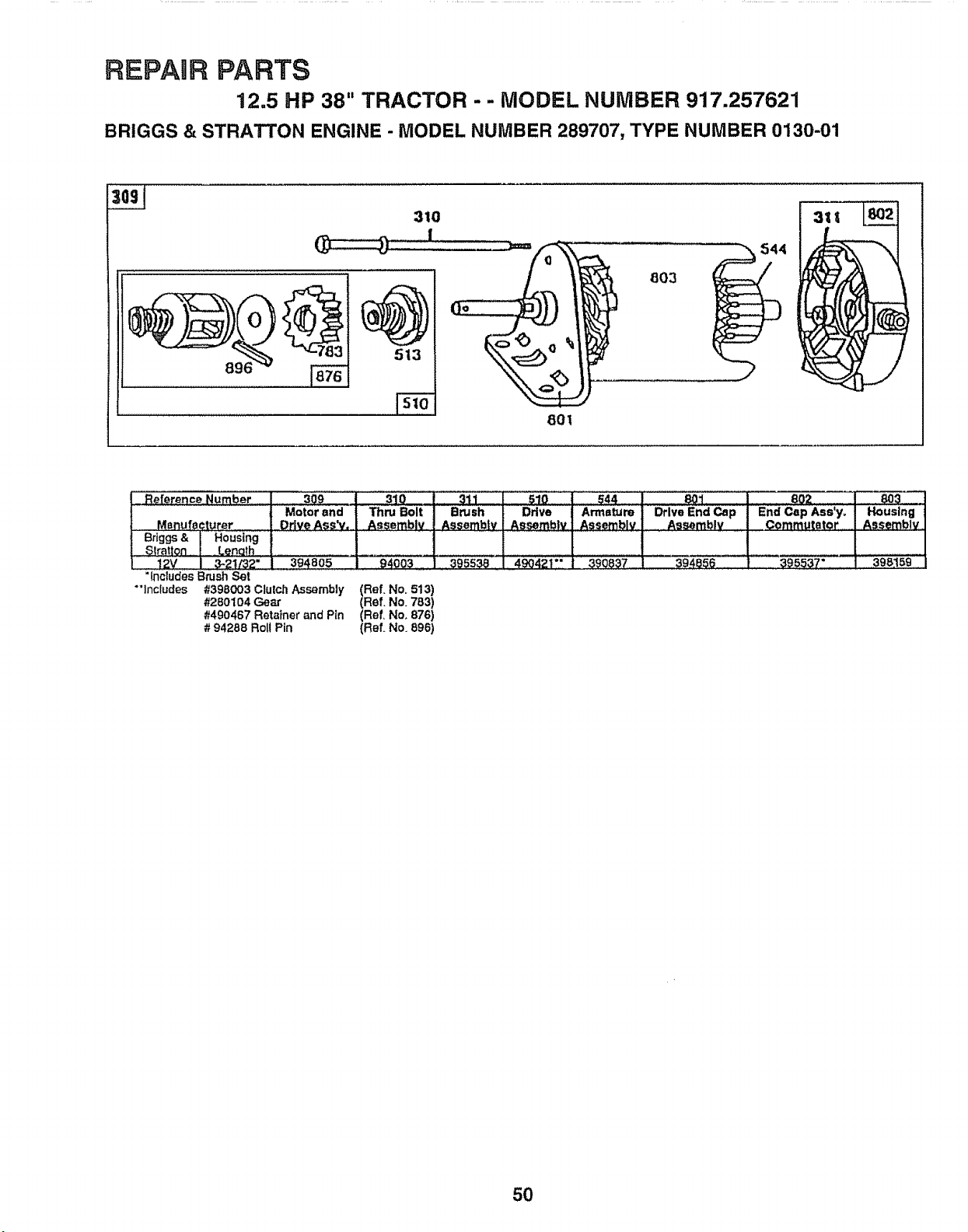
REPAIR PARTS
12.5 HP 38" TRACTOR - - MODEL NUMBER 917.257621
BRIGGS & STRATTON ENGINE - MODEL NUMBER 289707, TYPE NUMBER 0130-01
896
:310
3
803
801
R_ference Number
:_ Menufecturer
Briggs & Housing
$][atton Lenolh
L 12v _Ir_2- LIIII3_48o5 i_ 194003..... 39_538:
"Includes Brush Set
"']nc{udes #398003 Ctutch Assembly (Ref. No, 513)
#280104 Gear (Ref. No. 783)
#490467 Retainer and Pin (Ref, No, 876)
# 94288 Rolt Pin (Re[ No. 896)
510
Ddve
Assemblv
544
Armetum
Assembly
' _1 802 _'i_"iI
Drive End Cap End Cap Ass'y. Housing
Assembly ,_gmmutator Assemblv_
39_e_6 a95537- 13oS_59
309 310
Motor and Th_ B0it
Drive Ass'v. Assembly
311
Brush
Assembfv
r
390837
50
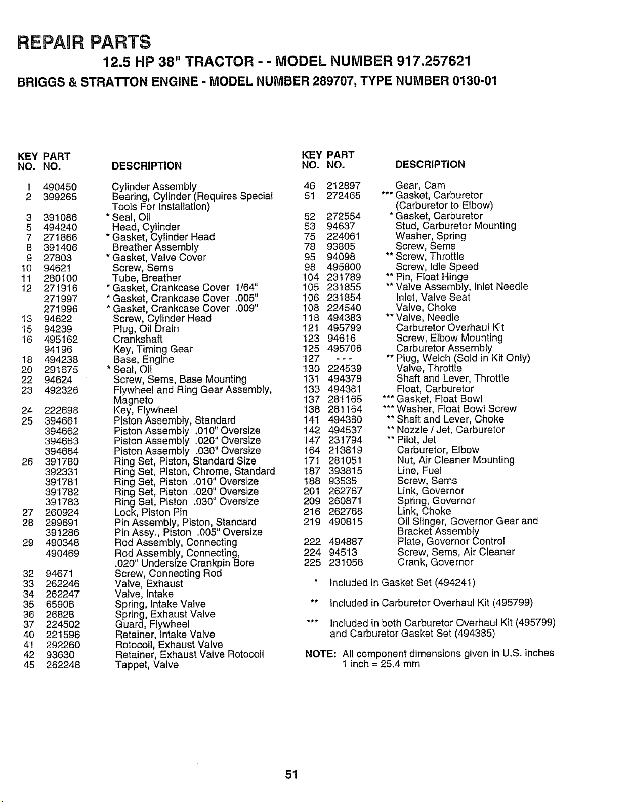
REPAURPARTS
12.5 HP 38" TRACTOR - - MODEL NUMBER 917.257621
BRIGGS & STRATTON ENGINE - MODEL NUMBER 289707, TYPE NUMBER 0130-01
KEY PART KEY PART
NO. NO. DESCRIPTION NO. NO. DESCRIPTION
1
2
490450
399265
3 391O86
5 494240
7 271866
8 391406
9 27803
10 94621
11 280100
12 271916
271997
271996
13 94622
!5 94239
16 495162
94196
18 494238
20 291675
22 94624
23 492326
24
25
26
27
28
29
32
33
34
35
36
37
40
41
42
45
222698
394661
394662
394663
394664
391780
392331
391781
391782
391783
260924
299691
391286
490348
490469
94671
262246
262247
65906
26828
224502
221596
292260
93630
262248
Cylinder Assembly 46
Bearing, Cylinder (Requires Speciat 51
Tools For Installation)
* Seal, Oil 52
Head, Cylinder 53
* Gasket, Cylinder Head 75
Breather Assembly 78
* Gasket, Valve Cover 95
Screw, Seres 98
Tube, Breather 104
* Gasket, Crankcase Cover 1/64" 105
* Gasket, Crankcase Cover °005" 106
* Gasket, Crankcase Cover _009" 108
Screw, Cylinder Head 118
Plug, Oil Drain 121
Crankshaft 123
Key, Timing Gear 125
Base, Engine '127
* Seal, Oi! 130
Screw, Seres, Base Mounting 131
Flywheel and Ring Gear Assembly, 133
Magneto 137
Key, Flywheel 138
Piston Assembly, Standard 141
Piston Assembly .010" Oversize 142
Piston Assembly .020" Oversize 147
Piston Assembly .030" Oversize 164
Ring Set, Piston, Standard Size 17I
Ring Set, Piston, Chrome, Standard 187
Ring Set, Piston o010" Oversize 188
Ring Set, Piston °020" Oversize 201
Ring Set, Piston .030" Oversize 209
Lock, Piston Pin 216
Pin Assembly, Piston, Standard 219
Pin Assy. Piston ,.005" Oversize
Rod Assembly, Connecting 222
Rod Assembly, Connecting, 224
.020" Undersize Crankpin Bore 225
Screw, Connecting Rod
Valve, Exhaust
Valve, Intake
Spring, Intake Valve
Spring, Exhaust Valve
Guard, Flywheel
Retainer, Intake Valve
Rotocoil, Exhaust Valve
Retainer, Exhaust Valve Rotocoil
Tappet, Valve
212897 Gear, Cam
272465 *** Gasket, Carburetor
(Carburetor to Elbow)
272554 * Gasket, Carburetor
94637 Stud, Carburetor Mounting
224061 Washer, Spring
93805 Screw, Sems
94098 ** Screw, Throttle
495800 Screw, Idle Speed
231789 ** Pin, FIoat Hinge
231855 ** Valve Assembly, Inlet Needle
231854 Inlet, Valve Seat
224540 Valve, Choke
494383 ** Valve, Needle
495799 Carburetor Overhaul Kit
94616 Screw, Elbow Mounting
495706 Carburetor Assembly
- - - ** Plug, Welch (Sold in Kit Only)
224539 Valve, Throttle
494379 Shaft and Lever, Throttle
494381 Float, Carburetor
281165 *** Gasket, Float Bow_
28I 164 *** Washer, Float Bowi Screw
494380 ** Shaft and Lever, Choke
494537 ** Nozzle / Jet, Carburetor
231794 ** Pilot, Jet
213819 Carburetor, Elbow
281051 Nut, Air Cleaner Mounting
393815 Line, Fuel
93535 Screw, Sems
262767 Link, Governor
260871 Spring, Governor
262766 Link, Choke
490815 Oil Slinger, Governor Gear and
Bracket Assembly
494887 Plate, Governor Control
945'13 Screw, Seres, Air Cleaner
231058 Crank, Governor
* Included in Gasket Set (494241)
** Included in Carburetor Overhaul Kit (495799)
*** Included in both Carburetor Overhaul Kit (495799)
and Carburetor Gasket Set (494385)
NOTE: All component dimensions given in UoSoinches
1 inch = 25.4 mm
51
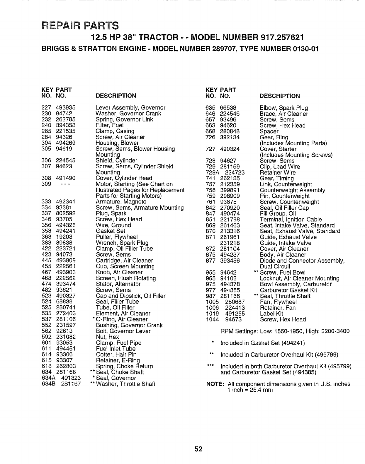
REPAIR PARTS
12.5 HP 38" TRACTOR - - MODEL NUMBER 917.257621
BRIGGS & STRATTON ENGINE - MODEL NUMBER 289707, TYPE NUMBER 0130-01
KEY PART KEY PART
NO. NO. DESCRIPTION NO. NO, DESCRIPTION
227 493935
230 94742
232 262785
24O 394358
265 221535
284 94326
304 494269
305 94619
306 224545
307 94623
308 491490
309 ---
333 492341
334 93381
337 802592
346 93705
356 494328
358 494241
363 19203
383 89838
422 223721
423 94073
445 493909
455 222561
467 493903
468 222562
474 393474
482 93621
523 490327
524 68838
525 280741
535 272403
537 281106
552 231597
562 92613
592 231082
601 93053
611 494451
614 93306
615 93307
618 262803
634 281168
634A 491323
634B 281167
_w
Lever Assembly, Governor 635 66538
Washer, Governor Crank 646 224546
Spring, Governor Link 657 93496
Filter, Fuel 663 94620
Clamp, Casing 668 280848
Screw, Air Cleaner 726 392134
Housing, Blower'
Screw, Sems, Blower Housing 727 490324
Mounting
Shield, Cylinder 728 94627
Screw, Serns, Cylinder Shield 729 281159
Mounting 729A 224723
Cover, Cylinder Head 741 262135
Motor, Starting (See Chart on 757 212359
Illustrated Pages for Replacement 758 399891
Parts for Starting Motors) 759 298909
Armature, Magneto 761 93875
Screw, Sems, Armature Mounting 842 270920
Plug, Spark 847 490474
Screw, Hex Head 851 221798
Wire, Ground 869 261463
Gasket Set 870 213316
Puller, Flywheel 871 261961
Wrench, Spark Plug 231218
Clamp, Oil Filler Tube 872 281104
Screw, Sems 875 494237
Cartridge, Air Cleaner 877 393456
Cup, Screen Mounting
Knob, Air Cleaner 955 94642
Screen, Flush Rotating 965 94108
Stator, Alternator' 975 494378
Screw, Sems 977 494385
Cap and Dipstick, Otl Filler 987 281166
Seal, Filler Tube t005 280687
Tube, OIl Filler t006 224413
Element, Air Cleaner 10!9 491255
O-Ring, AirCleaner 1044 94673
Bushing, Governor Crank
Bolt, Governor Lever
Nut, Hex
Clamp, Fuel Pipe
Fuel inlet Tube
Cotter, Hair Pin
Retainer, E-Ring
Spring, Choke Return
Seal, Choke Shaft
Seal, Governor
Washer, Throttle Shaft
Elbow, Spark Plug
Brace, Air Cleaner
Screw, Sems
Screw, Hex Head
Spacer
Gear, Ring
(includes Mounting Parts)
Cover, Starter
(Includes Mounting Screws)
Screw, Seres
Clip, Lead Wire
Retainer Wire
Gear, Timing
Link, Counterweight
Counterweight Assembly
Pin, Counterweight
Screw, Countenweight
Seat, Oil Filler Cap
Fill Group, Oil
Terminal, Ignition Cable
Seat, Intake Valve, Standard
Seat, Exhaust Valve, Standard
Guide, Exhaust Valve
Guide, Intake Valve
Cover, Air Cleaner'
Body, Air Cleaner
Diode and Connector Assembly,
Dual Circuit
** Screw, Fuel Bowl
Locknut, Air Cleaner Mounting
Bowl Assembly, Carburetor
Carburetor Gasket Kit
** Seal, Throttle Shaft
Fan, Flywheel
Retainer, Fan
Label Kit
Screw, Hex Head
RPM Settings: Low: t550-1950, High: 3200-3400
* included in Gasket Set (494241)
** Included in Carburetor Overhaul Kit (495799)
*** Included in both Carburetor Overhaut Kit (495799)
and Carburetor Gasket Set (494385)
NOTE: All component dimensions given in U.S. inches
1 inch = 25.4 mm
52

53

CE NOTES
............................... i II IIIII IIIIIIIIIIIIHIIIIIIIIIIIIII :T: T: :T _ = .
54
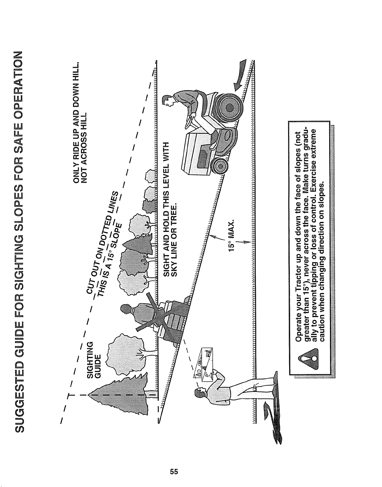
0
rr
W
0
LU
LL
0
LL,
W
n
0
J
0
0
U)
rr
0
LL
LLI
m
r_
Lu
u)
LU
U)
J
_J
-1-
0
2:..I
O.
O3
LUo
D:O
-JI-
zO
Oz
/
/
/
/-
/
/
0
/
/
/
/ o
/
/
/
/
55

OWNE '
UAL
MODEL NO.
917.257621
IF YOU NEED
REPAIR SERVICE
OR PARTS:
FOR REPAIR SERVICE, CALL
THIS TOLL FREE NUMBER:
1-800-4-REPAIR
(1-800-473-7247)
FOR REPLACEMENT PARTS
INFORMATION AND
ORDERING, CALL THIS
TOLL FREE NUMBER:
1-800-FON-PART
(1-800-366-7278)
®
12.5 HP OHV
ELECTRIC START
38" MOWER ,
5 SPEED TRANSAXLE
LAWN TRACTOR
Each tractor has its own model number. Each engine has
its own model number.
The model number for your tractor wii_ be found on the
model plate located under the seat.
The model number for your' engine will be found on the
blower housing of the engine.
Atl parts listed herein may be ordered from any Sears,
Roebuck and Co. Service Center/Department and most Re-
tail Stores._
WHEN ORDERING REPAIR PARTS, ALWAYS GIVE THE
FOLLOWING INFORMATION:
- PRODUCT - TRACTOR
• MODEL NUMBER - 9t7.257621
° ENGINE MODEL NO. - 289707, TYPE NO. 0130-01
,, PART NUMBER
° PART DESCRIPTION
Your Sears merchandise has added value when you
consider Sears has service units nationwide staffed with
Sears trained technicians_° professional technicians
specifically trained to insure that we meet our pledge to
you, we service what we sell.
142374 Rev. 2 06.08_94 Printed in UoS.A.
IIIIIIIIIIIIIIIIIIIIIIIIIIIIIIIIIIIIIIIIII I


