
Loading ...
Loading ...
Loading ...
6 7
OPERATING INSTRUCTIONS
CONTINUITY
Remove power from circuit. Test for continuity by applying test leads
to the system being tested. The tester automatically enters continuity
testing mode. If resistance < 270kΩ is detected, an audible signal will
sound and the continuity icon "
" will show in the display indicating
continuity. If the circuit is open, "
" will show in the display.
DO NOT attempt to measure continuity on a live circuit.
AC/DC VOLTAGE (LESS THAN 600V)
Apply test leads to the system under test to measure voltage; the
voltage measured will be reflected in the display. The tester will
automatically detect the presence of AC or DC voltage and illuminate
the appropriate icon in the display.
NOTE: Test-leads seated in the lead holders on the back of the tester
are spaced correctly to test tamper-resistant US-style outlets.
C
AUTION: The maximum testing voltage is 600V. ‘OL’ will show
in the display if voltage in excess of 600V is detected. No other
warnings will be delivered for voltages above 600V. Testing voltages
above 600V should not be attempted under any circumstances.
ENGLISH
OPERATING INSTRUCTIONS
TESTING IN CAT III / CAT IV MEASUREMENT LOCATIONS
Ensure the test lead shield is pressed firmly in place. Failure to use
the CAT III / CAT IV shield increases arc-flash risk.
TESTING IN CAT II MEASUREMENT LOCATIONS
CAT III / CAT IV shields may be removed for CAT II locations. This
will allow testing on recessed conductors such as standard wall
outlets. Take care not to lose the shields.
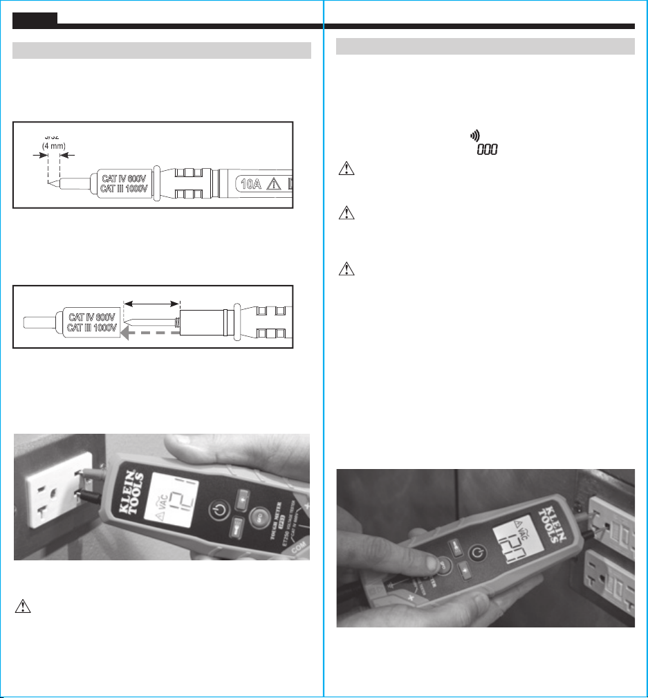
GFCI TESTING
CAUTION: Check the GFCI Receptacle user manual for more
information. Always contact a quali ed electrician to resolve wiring
problems. Operate the Test Button on the GFCI Receptacle. If the
GFCI circuit does not trip, the receptacle is not operating properly.
CAUTION: To resolve wiring or GFCI concerns, contact a
quali ed electrician.
To test the functionality of a receptacle protected by a Ground Fault
Circuit Interrupter (GFCI), apply leads to the hot/live and ground
terminals. Press the GFCI Test button on the ET250 tester.
• If the GFCI device is wired properly, the GFCI will trip and the
circuit will become de-energized. The ET250 tester will stop
indicating voltage.
• If the GFCI receptacle is incorrectly wired, the power to the circuit
will remain and the ET250 will continue to indicate voltage. Contact
a qualified electrician to resolve wiring problems.
NOTE: The GFCI Test mode on this tester is deactivated in the
presence of voltages > 135V.
0.7" (18 mm)
5/32"
(4 mm)
5/32
(4 mm)
Loading ...
Loading ...
Loading ...