Loading ...
Loading ...
Loading ...
3. Threadthe hosecoupler(packagedwithyourtractor'sOperator's
Manual)ontothe end of your gardenhose.
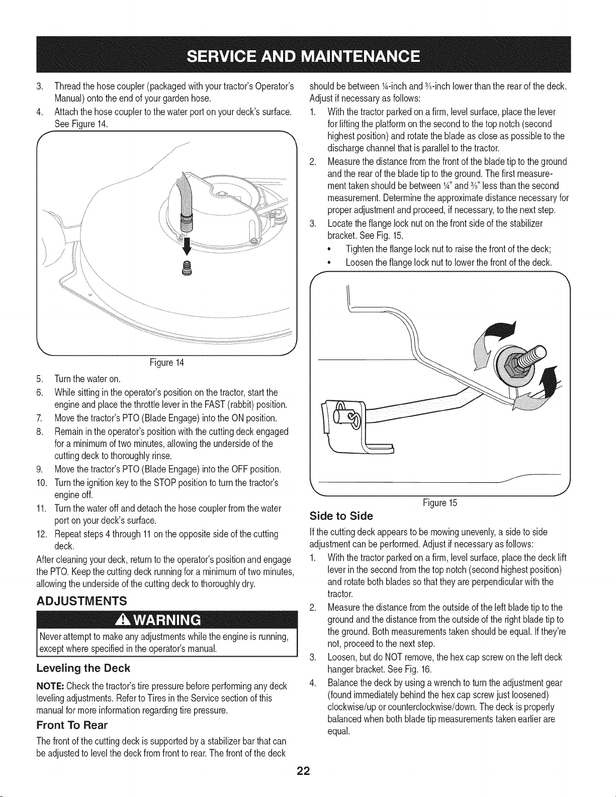
4. Attachthe hosecouplerto the waterport onyourdeck'ssurface.
SeeFigure14.
J
j,
/
f
J _; .......... ........
8
Figure14
5. Turnthe wateron.
6. Whilesittinginthe operator'spositiononthe tractor,startthe
engineandplacethe throttleleverinthe FAST(rabbit)position.
7. Movethe tractor'sPTO(BladeEngage)intothe ON position.
8. Remaininthe operator'spositionwiththecuttingdeckengaged
for a minimumof two minutes,allowingthe undersideof the
cuttingdeckto thoroughlyrinse.
9. Movethe tractor'sPTO(BladeEngage)intothe OFFposition.
10. Turnthe ignitionkeytothe STOPpositionto turnthe tractor's
engineoff.
11. Turnthe wateroff anddetachthe hosecouplerfromthe water
port on yourdeck'ssurface.
12. Repeatsteps4through11on the oppositeside of the cutting
deck.
Aftercleaningyourdeck, returnto the operator'spositionand engage
the PTO.Keepthe cuttingdeckrunningfor a minimumof twominutes,
allowingthe undersideof thecuttingdeck to thoroughlydry.
ADJUSTMENTS
Neverattemptto makeanyadjustmentswhilethe engineis running,
exceptwherespecifiedin the operator'smanual.
Leveling the Deck
NOTE: Checkthe tractor'stire pressurebeforeperforminganydeck
levelingadjustments.Referto Tires in the Servicesectionof this
manualfor moreinformationregardingtire pressure.
Front To Rear
Thefrontof the cuttingdeckis supportedby a stabilizerbar that can
beadjustedto levelthe deckfrom front to rear.Thefrontof the deck
shouldbe between_A-inchand 3A-inchlowerthanthe rearof the deck.
Adjustif necessaryas follows:
1. Withthe tractorparkedon a firm, levelsurface,placethe lever
for lifting the platformon the secondto the top notch(second
highestposition)and rotatethe bladeas closeas possibleto the
dischargechannelthat is parallelto the tractor.
2. Measurethedistancefromthe frontof the bladetip to the ground
andthe rearof the bladetip to theground.Thefirst measure-
menttakenshouldbe between_A"and3A"less thanthe second
measurement.Determinethe approximatedistancenecessaryfor
properadjustmentandproceed,if necessary,to the nextstep.
3. Locatethe flangelocknut on the frontsideof the stabilizer
bracket.SeeFig. 15.
• Tightenthe flangelock nut to raisethe frontof the deck;
Loosentheflangelock nutto lowerthe frontof thedeck.
o
f
f__
Side to Side
Figure15
J
Ifthe cuttingdeck appearsto be mowingunevenly,a sideto side
adjustmentcan be performed.Adjustif necessaryas follows:
1. Withthe tractorparkedon a firm, levelsurface,placethe deck lift
leverin the secondfromthe top notch (secondhighestposition)
and rotatebothbladessothat theyare perpendicularwiththe
tractor.
2. Measurethedistancefromthe outsideof the left bladetip to the
groundandthe distancefromthe outsideof the rightblade tip to
the ground.Bothmeasurementstakenshouldbe equal.If they're
not, proceedto the nextstep.
3. Loosen,but do NOTremove,the hexcap screwon the left deck
hangerbracket.SeeFig. 16.
4. Balancethedeck by usinga wrenchto turn theadjustmentgear
(foundimmediatelybehindthehex cap screwjust loosened)
clockwise/uporcounterclockwise/down.Thedeck is properly
balancedwhen bothbladetip measurementstakenearlierare
equal.
22
Loading ...
Loading ...
Loading ...