
23-08-312-932965 REV E
HC350S, HCINT350S Series Power Module Application Guidelines
Series AGSM5396, AGTR0829
SAVE THESE INSTRUCTIONS – This manual contains IMPORTANT SAFETY
INSTRUCTIONS for that should be followed during installation and maintenance of the
UPS and batteries.
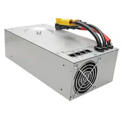
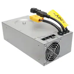
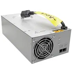
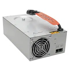
The HC350S and HCINT350S series of hospital cart power modules are designed to
provide AC voltage output power from either utility provided AC input voltage or from
inverting 12VDC power from a sealed lead acid battery. To ensure proper operation the
following guidelines should be observed:
1. The power module can support AC loads up to a maximum of 400VA or 300W.
2. The power module charger is intended to be used with a 12V sealed lead acid
absorbed glass mat (AGM) battery with a 33Ah to 66Ah rating. Batteries rated at
less than 33AH are not recommended since the charger current of 12A would
reduce the battery cycle life of smaller batteries.
3. The appliance inlet dongle serves as a disconnect device and shall be easily
accessible.
4. Alternately, the socket-outlet of the end-product shall be installed near the
equipment and shall be easily accessible or disconnect device provided within
the end-product.
5. Adequate provision for airflow needs to be provided at both the inlet and outlet
vents of the power module. There should be at least 0.5 inches of clear space on
the fan end and on the vented end of the power module. A baffle or air deflector
is recommended at the fan end so that the air intake is raised at least 6 inches
above floor level to prevent dust accumulation inside the power module.
6. The power module may be mounted in any orientation. Four 8-32 threaded
inserts are provided on the surface with the AC input cord to facilitate mounting.
7. The AC voltage input and output connections are made with user supplied cables
to the IEC input and output connectors on the power module. Use only with
approved plug/cord sets according to the equipment electrical ratings. No
external fusing is needed since safe operation is assured by internal non-
replaceable 10A fuses. However, if a customer wishes to prevent the internal
fuses from blowing in the event of an extreme overload, then an external fuse or
circuit breaker rated at 6A to 10A (120VAC models) or 3A to 5A (230V models)
should be provided on the AC voltage input.
8. The 12V battery input is made with a user supplied cable to the Anderson DC
connector on the power module. Proper polarity must be observed. The
recommended wire size is 8AWG in order to keep the voltage drop in the cable to
less than 0.1V. The length of cable between the battery and the power module
should be less than 30 inches. A user supplied 40A to 50A automotive style fuse
is required in the positive lead of the battery (within 18 inches of the battery
positive terminal).
1000 Eaton Boulevard
Cleveland, OH 44122
United States
TrippLite.Eaton.com
Tripp Lite is now part of Eaton.

23-08-312-932965 REV E
9. Additional bonding is needed to connect the battery negative terminal to the case
of the power module. The wire (or metal frame of the cart) should be short (less
than 18 inches) and preferably of the same gauge as the other battery wires
(although a minimum gauge of 16AWG has been acceptable). This bonding
connection is necessary to prevent internal damage to the power module in the
event of any accidental reversed polarity connections or accidental connections
between the battery positive wiring and the case of the power module.
10. A Remote User Interface (RUI) module must be connected to the power module
using two CAT-5 cables. The COMM1 jacks should be connected together and
the COMM2 jacks should be connected together. If the cables are not connected
or if they are interchanged, the power module will not operate. The RUI may be
either a Tripp Lite RUI or a customer designed RUI that meets Tripp Lite
specifications.
11. The power module includes a low voltage cutoff (LVC) function that will remove
any load on the battery when the battery is depleted. The LVC level is about
10.5V to assure optimum battery cycle life. If any other DC loads are present in
the system, they need to include their own LVC function in order to prevent
damage to the battery due to over discharge.
12. The power module will not turn on unless connected to a battery that has a
voltage greater than 9.6V. If the battery voltage is less than 9.6V, it is assumed
to be defective and the charger is inhibited in order to prevent possible
outgassing of the battery.
13. The power module reports % Battery Capacity through its USB port. This data is
most accurate when a 55Ah sealed lead acid absorbed glass mat (AGM) battery
is used. Batteries of other capacities may be used, but the accuracy of the
% Battery Capacity report will be reduced.
14. After connecting a battery to the power module, the power module should be
allowed to charge the battery to full capacity in order to initialize the % Battery
Capacity report and the % Battery Capacity LED’s (on the RUI). This will take at
least 4 hours, even with fresh battery. The % Battery Capacity report and LED’s
will not be accurate until after the initial charge has been completed. After
initialization, the power module will properly indicate the % Battery Capacity as
the battery is repeatedly discharged and recharged. However, each time the
battery is replaced, the initialization will need to be repeated.
15. CAUTION: Double Pole/Neutral Fusing.
Technical Details
T
y
pe of electrical suppl
y
s
y
stem: TN
In
g
ress protection: IP20
Stora
g
e environment: 0 to 95% RH non-condensin
g
, 32-122Fº
(
0-50ºC
)
.
A
mbient operatin
g
temperature ran
g
e: 32-104Fº
(
0-40ºC
)
Relevant standards for manufacture, test, or use: IEC/EN 62040-1, IEC 60601-1

23-08-312-932965 REV E
Guías de Aplicación para los Módulos de Potencia de las Series
HC350S y HCINT350S
Series AGSM5396, AGTR0829
GUARDE ESTAS INSTRUCCIONES – Este manual contiene INSTRUCCIONES DE
SEGURIDAD IMPORTANTES que deben seguirse durante la instalación y el
mantenimiento del UPS y las baterías.
Los módulos de potencia para carros de hospital de las series HC350S y HCINT350S
están diseñados para proporcionar una potencia de salida de voltaje de CA
suministrada por la red pública o a partir de la inversión de potencia de 12VCD de una
batería de plomo-ácido sellada. Para garantizar el funcionamiento correcto, deben
seguirse las siguientes guías:
1. El módulo de potencia puede admitir cargas de CA hasta un máximo de 400VA o
300W.
2. El cargador del módulo de potencia está diseñado para usarse con una batería
de fibra de vidrio absorbente [AGM] sellada de 12V con especificación de 33Ah a
66Ah . No se recomienda el uso de baterías con especificación menor que 33Ah
ya que la corriente del cargador de 12A reduciría el ciclo de vida de la batería en
el caso de las baterías más pequeñas.
3. El dongle de entrada del aparato sirve como dispositivo de desconexión y
deberá ser fácilmente accesible.
4. Alternativamente, el tomacorriente del producto final se debe instalar cerca del
equipo y debe ser fácilmente accesible o se proporcionará un dispositivo de
desconexión dentro del producto final.
5. Es necesario proporcionar un flujo de aire adecuado en las rejillas de entrada y
de salida del módulo de potencia. Debe haber al menos 1.3 cm [0.5"] de espacio
libre en el extremo del ventilador y en el extremo ventilado del módulo de
potencia. Se recomienda colocar un deflector de aire en el extremo del ventilador
de modo que la entrada de aire se eleve al menos 15 cm [6"] sobre el nivel del
suelo para evitar la acumulación de polvo en el módulo de potencia.
6. El módulo de potencia puede instalarse en cualquier orientación. Para facilitar la
instalación, se proporcionan cuatro insertos roscados 8-32 sobre la superficie
con el cable de alimentación de CA.
7. Las conexiones de entrada y salida del voltaje de CA están hechas con cables
suministrados por el usuario a los conectores IEC de entrada y salida en el
módulo de potencia. Utilice solo con una clavija y cable de alimentación
aprobados según las especificaciones eléctricas del equipo. No se necesitan
fusibles externos ya que la operación segura está garantizada por fusibles
internos de 10A no reemplazables. Sin embargo, si un cliente desea evitar que
los fusibles internos se quemen en caso de una sobrecarga extrema, entonces
debe instalar un fusible externo o breaker de 6A a 10A (modelos de 120VCA) o
3A a 5A (modelos de 230V) en la entrada de voltaje de CA.
8. La entrada de la batería de 12V está hecha con un cable suministrado por el
usuario al conector de CD Anderson en el módulo de potencia. Debe respetarse
la polaridad correcta. El calibre de cable recomendado es 8AWG a fin de

23-08-312-932965 REV E
mantener la caída de voltaje en el cable a menos de 0.1V. La longitud del cable
entre la batería y el módulo de potencia debe ser inferior a 76 cm [30"]. Se
requiere un fusible de 40A a 50A de tipo automotriz proporcionado por el usuario
en el contacto positivo de la batería (a menos de 46cm [18"] del terminal positivo
de la batería).
9. Se necesita una conexión adicional para conectar la terminal negativa de la
batería al gabinete del módulo de potencia. El cable (o bastidor metálico del
carro) debe ser corto (menos de 45.7 cm [18"]) y preferentemente del mismo
calibre que los otros cables de la batería (aunque es aceptable un calibre
mínimo de 16AWG). Esta conexión es necesaria para evitar daños internos en el
módulo de potencia en caso de cualquier conexión accidental de polaridad
invertida o conexiones accidentales entre el cableado positivo de la batería y el
gabinete del módulo de potencia.
10. Debe conectarse un Módulo de Interfaz de Usuario Remoto [RUI] al módulo de
potencia usando dos cables CAT-5. Los conectores COMM1 deben conectarse
juntos y los conectores COMM2 también deben conectarse juntos. Si los cables
no están conectados o si están intercambiados, el módulo de potencia no
funcionará. El RUI puede ser un RUI de Tripp Lite o un RUI diseñado por el
cliente que cumpla con las especificaciones de Tripp Lite.
11. El módulo de potencia incluye una función de corte por voltaje bajo [LVC] que
eliminará cualquier carga en la batería cuando la batería esté agotada. El nivel
de LVC es de alrededor de 10.5V para asegurar un ciclo de vida óptimo de la
batería. Si hay otras cargas de CD presentes en el sistema, necesitan incluir su
propia función de LVC a fin de evitar daños a la batería debidos a
sobredescarga.
12. El módulo de potencia no encenderá a menos que esté conectado a una batería
que tenga un voltaje superior a 9.6V. Si el voltaje de la batería es inferior a 9.6V,
se supone que está defectuoso y se inhibe el cargador a fin de evitar una posible
liberación de gases de la batería.
13. El módulo de potencia reporta el % de Capacidad de la Batería a través de su
puerto USB. Estos datos son más precisos cuando se utiliza una batería de
plomo ácido sellada de 55Ah de fibra de vidrio absorbente [AGM]. Pueden
usarse baterías de otras capacidades, pero se reducirá la precisión del informe
de Capacidad de la Batería.
14. Después de conectar una batería al módulo de potencia, se debe permitir al
módulo de potencia cargar la batería a plena capacidad a fin de iniciar el informe
de % de Capacidad de la Batería y el LED de % de Capacidad de la Batería (en
el RUI). Esto tomará al menos 4 horas, incluso con la batería nueva. El informe
del % de capacidad de la batería y los LED no serán precisos hasta después de
completar la carga inicial. Después de la inicialización, el módulo de potencia
indicará correctamente el % de Capacidad de la Batería conforme la batería se
descargue y recargue repetidamente. Sin embargo, cada vez que se reemplace
la batería, será necesario repetir la inicialización.
15. PRECAUCIÓN: Fusible Bipolar / Neutro.

23-08-312-932965 REV E
Detalles técnicos
Tipo de sistema de suministro eléctrico: TN
Protección contra la penetración: IP20
Entorno de Almacenamiento: 0% a 95% de HR, Sin Condensación, 0 ºC ~ 50 ºC [32
ºF ~ 122°F] .
Ran
g
o de temperatura de operación ambiente: 0 ºC ~ 40 ºC [32 ºF ~ 104 ºF]
Estándares relevantes para fabricación, prueba o uso: IEC/EN 62040-1, IEC 60601-1

23
-08-312-932965 REV E
HC350S, HCINT350S-Baureihe Leistungsmodul -
Applikationsrichtlinien
Baureihe AGSM5396, AGTR0829
BEWAHREN SIE DIESE ANWEISUNGEN AUF – Dieses Handbuch enthält WICHTIGE
SICHERHEITSHINWEISE, die bei der Installation und Wartung der USV und Batterien
beachtet werden sollten.
Die Leistungsmodule der HC350S- und HCINT350S-Baureihe für Krankenhauswagen
sind so konzipiert, dass die Ausgangsleistung der AC-Spannung entweder von der
bereitgestellten AC-Eingangsspannung des Versorgungsunternehmens oder durch die
Invertierung der 12-VDC-Leistung einer versiegelten Bleisäure-Batterie geliefert wird.
Um einen ordnungsgemäßen Betrieb zu gewährleisten, sollten die folgenden Richtlinien
befolgt werden:
1. Das Leistungsmodul kann AC-Lasten bis zu 400 VA oder 300 W unterstützen.
2. Das Leistungsmodul-Ladegerät ist für die Verwendung mit einer versiegelten 12-
V-Bleisäure-AGM-Batterie (Absorbed Glass Mat) mit einer Leistung von 33 AH
bis 66 AG vorgesehen. Batterien mit einer Nennleistung von weniger als 33 AH
werden nicht empfohlen, da der Ladestrom von 12 A die Lebensdauer von
kleineren Batterien verkürzen würde.
3. Der Geräteeingang-Dongle dient als Trennvorrichtung und muss leicht
zugänglich sein.
4. Alternativ muss die Steckdose des Endprodukts in der Nähe des Geräts
installiert und leicht zugänglich sein, oder es muss eine Trennvorrichtung im
Endprodukt vorhanden sein.
5. An den Eingangs- und Ausgangsöffnungen des Leistungsmoduls muss ein
ausreichender Luftstrom bereitgestellt werden. Am Lüfterende und am belüfteten
Ende des Leistungsmoduls sollte ein Freiraum von mindestens 1,3 cm
vorhanden sein. Am Lüfterende wird ein Ablenkblech oder Luftleitblech
empfohlen, damit sich die Luftansaugung mindestens 15 cm über dem Boden
befindet, um eine Staubansammlung im Inneren des Leistungsmoduls zu
verhindern.
6. Das Leistungsmodul kann in beliebiger Ausrichtung montiert werden. Vier 8-32
Gewindeeinsätze werden mit dem AC-Eingangskabel auf der Oberfläche
bereitgestellt, um die Montage zu erleichtern.
7. Die Eingangs- und Ausgangsverbindungen für die AC-Spannung werden mit vom
Benutzer bereitgestellten Kabeln zu den IEC-Eingangs- und
Ausgangsanschlüssen des Leistungsmoduls hergestellt. Dürfen nur mit
zugelassenen Steckern/Kabelsätzen gemäß den elektrischen Werten des Geräts
verwendet werden. Eine externe Sicherung ist nicht erforderlich, da der sichere
Betrieb durch interne, nicht austauschbare 10-A-Sicherungen gewährleistet ist.
Wenn ein Kunde jedoch verhindern möchte, dass die internen Sicherungen im
Falle einer extremen Überlastung durchbrennen, sollte auf dem AC-
Spannungseingang eine externe Sicherung oder ein Leistungsschalter mit einer
Nennleistung von 6 A bis 10 A (120-VAC-Modelle) oder 3 A bis 5 A (230-V-
Modelle) bereitgestellt werden.

23-08-312-932965 REV E
8. Der 12-V-Batterieeingang wird mit einem vom Benutzer bereitgestellten Kabel an
den Anderson DC-Anschluss des Leistungsmoduls hergestellt. Die richtige
Polarität muss beachtet werden. Die empfohlene Kabelgröße beträgt 8 AWG, um
den Spannungsabfall im Kabel auf weniger als 0,1 V zu halten. Die Kabellänge
zwischen Batterie und Leistungsmodul sollte weniger als 76 cm betragen. Eine
vom Benutzer bereitgestellte 40 A bis 50 A Automotive-Sicherung ist im positiven
Anschluss der Batterie erforderlich (innerhalb von 45 cm vom Pluspol der
Batterie).
9. Eine zusätzliche Verbindung ist erforderlich, um den Minuspol der Batterie an
das Gehäuse des Leistungsmoduls anzuschließen. Der Draht (oder
Metallrahmen des Wagens) sollte kurz (weniger als 45 cm) und vorzugsweise
von der gleichen Stärke wie die anderen Batteriekabel sein (obwohl eine
Mindeststärke von 16 AWG akzeptabel ist). Dieser Verbindungsanschluss ist
erforderlich, um eine interne Beschädigung des Leistungsmoduls bei
versehentlichen Verpolungsanschlüssen oder versehentlichen Verbindungen
zwischen der positiven Verkabelung der Batterie und dem Gehäuse des
Leistungsmoduls zu verhindern.
10. Ein RUI-Modul (Remote User Interface) muss mit zwei CAT-5-Kabeln an das
Leistungsmodul angeschlossen werden. Die COMM1-Buchsen sowie die
COMM2-Buchsen sollten jeweils miteinander verbunden werden. Wenn die
Kabel nicht angeschlossen sind oder ausgetauscht werden, funktioniert das
Stromversorgungsmodul nicht. Die RUI kann entweder eine RUI von Tripp Lite
oder ein vom Kunden entwickeltes RUI sein, das die Spezifikationen von Tripp
Lite erfüllt.
11. Das Leistungsmodul enthält eine Funktion zur Abschaltung der Niederspannung
(LVC), die jede Last auf der Batterie beseitigt, wenn die Batterie leer ist. Der
LVC-Pegel beträgt ca. 10,5 V, um eine optimale Lebensdauer der Batterie zu
gewährleisten. Wenn andere DC-Lasten im System vorhanden sind, müssen
diese eine eigene LVC-Funktion enthalten, um Schäden an der Batterie durch
Überentladung zu verhindern.
12. Das Leistungsmodul schaltet sich nur ein, wenn es an eine Batterie mit einer
Spannung von mehr als 9,6 V angeschlossen ist. Wenn die Batteriespannung
weniger als 9,6 V beträgt, wird davon ausgegangen, dass sie defekt ist und das
Ladegerät blockiert ist, um ein mögliches Ausgasen der Batterie zu verhindern.
13. Das Leistungsmodul meldet über seinen USB-Anschluss eine Batteriekapazität
in %. Diese Daten sind am genauesten, wenn eine versiegelte 55-AH-Bleisäure-
AGM-Batterie (Absorbed Glass Mat) verwendet wird. Es können Batterien mit
anderen Kapazitäten verwendet werden, aber die Genauigkeit des Berichts über
die Batteriekapazität in % wird reduziert.
14. Nachdem eine Batterie an das Leistungsmodul angeschlossen wurde, sollte das
Leistungsmodul die Batterie auf volle Kapazität laden können, um den Bericht
über die Batteriekapazität in % und die LED-Werte für die Batteriekapazität in %
(auf der RUI) zu initialisieren. Dies dauert auch bei einer neuen Batterie
mindestens 4 Stunden. Der Bericht über die Batteriekapazität in % und die LED-
Werte sind erst nach Abschluss der ersten Aufladung korrekt. Nach der
Initialisierung zeigt das Leistungsmodul die Batteriekapazität in % an, wenn der
Akku wiederholt entladen und aufgeladen wird. Jedes Mal, wenn die Batterie
ersetzt wird, muss die Initialisierung wiederholt werden.
23-08-312-932965 REV E
15. ACHTUNG: Zweipolig/Neutral Absicherung.
Technische Daten
A
rt des elektrischen Versor
g
un
g
ss
y
stems: TN
Schutz vor Eindrin
g
en: IP20
Speicherum
g
ebun
g
: 0 bis 95 % RF, nicht kondensierend, 0 bis 50 ºC.
Um
g
ebun
g
sbetriebstemperaturbereich: 0 bis 40 °C
Einschlägige Normen für die Herstellung, Prüfung oder Verwendung: IEC/EN 62040-
1, IEC 60601-1
1000 Eaton Boulevard
Cleveland, OH 44122
United States
TrippLite.Eaton.com