
PANS_E 2000
2.5 HP " 0" 10 MPH " POWER INCLINE " EXPANDED RUNNING SURFACE
Model No. 831.297271
Serial No.
The serialnumber can be found in the
locationshown below. Write the serial
number in the space above.
Serial Number
_k CAUTION!:
Read all safety precautions
and instructions in this
manual before using this
equipment. Keep this
manual in a safe place for
future reference.
OWNER'S MANUAL
IMPORTANT SAFETY PRECAUTIONS
I WARNING: To reduce the risk of burns, fire, electric shock or Injury to persons, read
the following Important safety precautions and Information before operating the treadmill.
.
Position the treadmill on a level surface, with at least 8 feet of clearance behind the tread-
mill. Do not place the treadmill near water, outdoors or on any surface that blocks an air
opening. Do not operate where aerosol products are used or where oxygen Is being admin-
Istered.
.
.
.
When connecting the power cord (see OPERATION AND ADJUSTMENT In this manual),
plug the power cord directly Into a grounded circuit capable of carrying 12 or more amps.
No other appliance should be on the same circuit. Keep the power cord away from heated
surfaces. If an extension cord Is needed, use only a 14-gauge general-purpose cord of five
feet or less In length with a three-wire conductor.
Never move the walking belt while the power Is turned off. Do not operate the treadmill If
the power cord or plug Is damaged, or If the treadmill Is not working properly. (See
BEFORE YOU BEGIN In this manual if the treadmill Is not working properly.)
Wear appropriate exercise clothing when using the treadmill; do not wear loose clothing
that could become caught In the treadmill. Always wear athletic shoes; never use the tread-
mill with bare feet, wearing only stockings or In sandals. Athletic support clothes are rec-
ommended for both men and women.
5. The pulse earcllp Is not a medical device. Various factors, Including the user's movement
while exercising, may affect the accuracy of heart rate readings. The earcllp is Intended
only as an exercise aid In determining heart rate trends in general.
6. Never start the treadmill while you are standing on the walking belt. Always hold the
handrail when exercising on the treadmill.
7. Never allow more than one person on the treadmill at a time. The treadmill should not be
used by persons weighing more than 250 pounds.
8. Keep small children away from the treadmill at all times. Never leave the treadmill
unattended while it Is running. Always turn the power off when the treadmill Is not In use.
9. Never drop or Insert any object Into any opening.
10. To reduce the possibility of overheating, do not operate the treadmill continuously for
longer than 1 hour.
11. The treadmill is capable of high speeds. Adjust the speed slowly to avoid sudden Jumps In
speed.
Use the treadmill only as described in this manual.
Always unplug the power cord before performing the maintenance and adjustment
procedures described in this manual. Never remove the safety cover unless Instructed to
do so by an authorized service representative. Servicing other than the procedures in this
manual should be performed by an authorized service representative only.
WARNING: Before beginning this or any exercise program, consult your physician.
This Is especially Important for persons over theage of 35 or persons with pre-exlsting health
problems. Read all Instructions before using. SEARS assumes no responsibility for personal
Injury or property damage sustained by or through the use of this product.
2 SAVE THESE INSTRUCTIONS
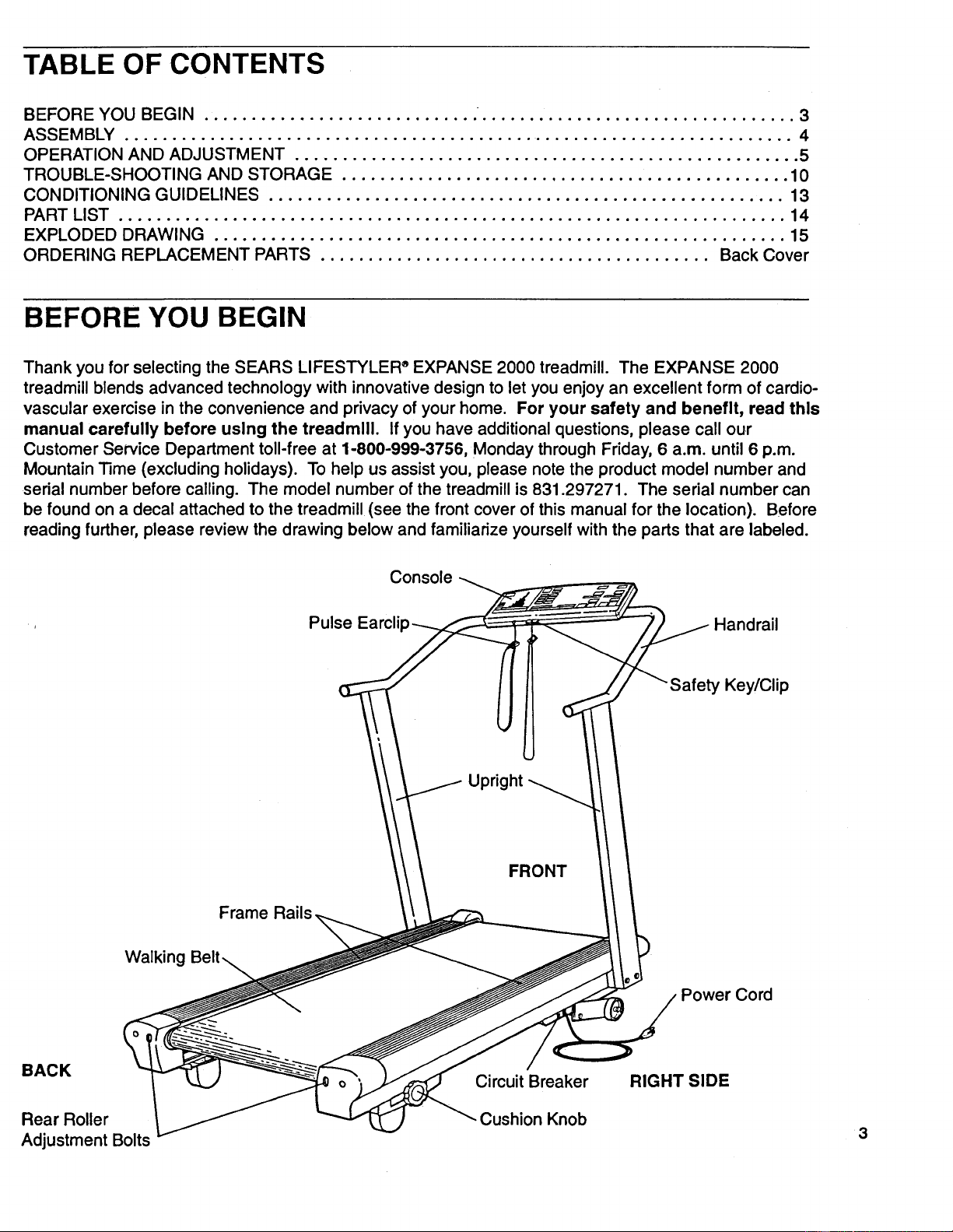
TABLE OF CONTENTS
BEFORE YOU BEGIN ............................. ................................. 3
ASSEMBLY ...................................................................... 4
OPERATION AND ADJUSTMENT ..................................................... 5
TROUBLE-SHOOTING AND STORAGE ............................................... 10
CONDITIONING GUIDELINES ...................................................... 13
PART LIST ...................................................................... 14
EXPLODED DRAWING ............................................................ 15
ORDERING REPLACEMENT PARTS ......................................... Back Cover
BEFORE YOU BEGIN
Thank you for selecting the SEARS LIFESTYLER _EXPANSE 2000 treadmill. The EXPANSE 2000
treadmill blends advanced technology with innovative design to let you enjoy an excellent form of cardio-
vascular exercise in the convenience and privacy of your home. For your safety and benefit, read this
manual carefully before using the treadmill. Ifyou have additional questions, please call our
Customer Service Department toll-free at 1-800-999-3756, Monday through Friday, 6 a.m. until 6 p.m.
Mountain Time (excluding holidays). To help us assist you, please notethe product model number and
serial number before calling. The model number of the treadmill is 831.297271. The serial number can
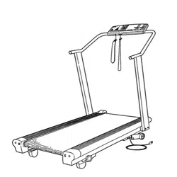
be found on a decal attached to the treadmill (see the front cover of this manual for the location). Before
reading further, please review the drawing below and familiarize yourself with the parts that are labeled.
Console
Pulse Earclip _l
. ht
Frame Rails.
Handrail
Key/Clip
Walking
BACK
Rear Roller
Adjustment Bolts
Circuit Breaker
Cushion Knob
Power Cord
RIGHT SIDE
3
ASSEMBLY
Set the treadmill in a cleared area and remove all packing materials. Do not dispose of the packing
materials until assembly is completed, TOOLS REQUIRED FOR ASSEMBLY: An 8" adjustable
wrench (not Included).
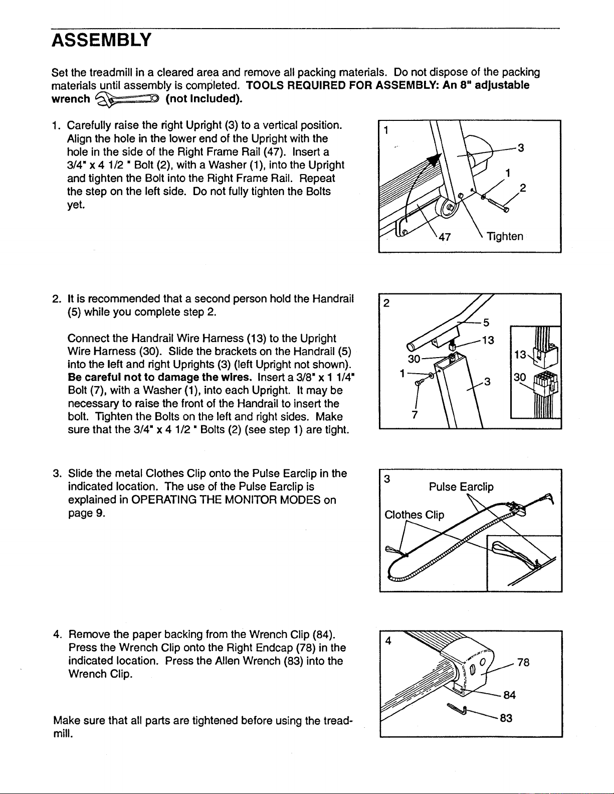
1. Carefully raise the right Upright (3) to a vertical position.
Align the hole in the lower end of the Upright with the
hole in the side of the Right Frame Rail (47). Insert a
3/4" x 4 1/2 " Bolt (2), with a Washer (1), into the Upright
and tighten the Bolt into the Right Frame Rail. Repeat
the step on the left side. Do not fully tighten the Bolts
yet.
2
47 righten
.
It is recommended that a second person hold the Handrail
(5) while you complete step 2.
Connect the Handrail Wire Harness (13) to the Upright
Wire Harness (30). Slide the brackets on the Handrail (5)
into the left and right Uprights (3) (left Upright not shown).
Be careful not to damage the wires. Insert a 3/8" x I 1/4"
Bolt (7), with a Washer (1), into each Upright. It may be
necessary to raise the front of the Handrail to insert the
bolt. Tighten the Bolts on the left and right sides. Make
sure that the 3/4" x 4 1/2" Bolts (2) (see step 1) are tight.
2
7
,
Slide the metal Clothes Clip onto the Pulse Earclip in the
indicated location. The use of the Pulse Earclip is
explained in OPERATING THE MONITOR MODES on
page 9.
3
Pulse Earclip
Clothes Clip
.
Remove the paper backing from the Wrench Clip (84).
Press the Wrench Clip onto the Right Endcap (78) in the
indicated location. Press the Allen Wrench (83) into the
Wrench Clip.
Make sure that all parts are tightened before using the tread-
mill.
78
84
OPERATION AND ADJUSTMENT
PLUGGING IN THE POWER CORD
This product must be grounded. If it should malfunction or break down, grounding provides a path
of least resistance for electric current to reduce the risk of electric shock. This product is equipped with
a cord having an equipment-grounding conductor and a grounding plug. Plug the power cord Into an
appropriate outlet that is properly Installed and grounded in accordance with all local codes
and ordinances.
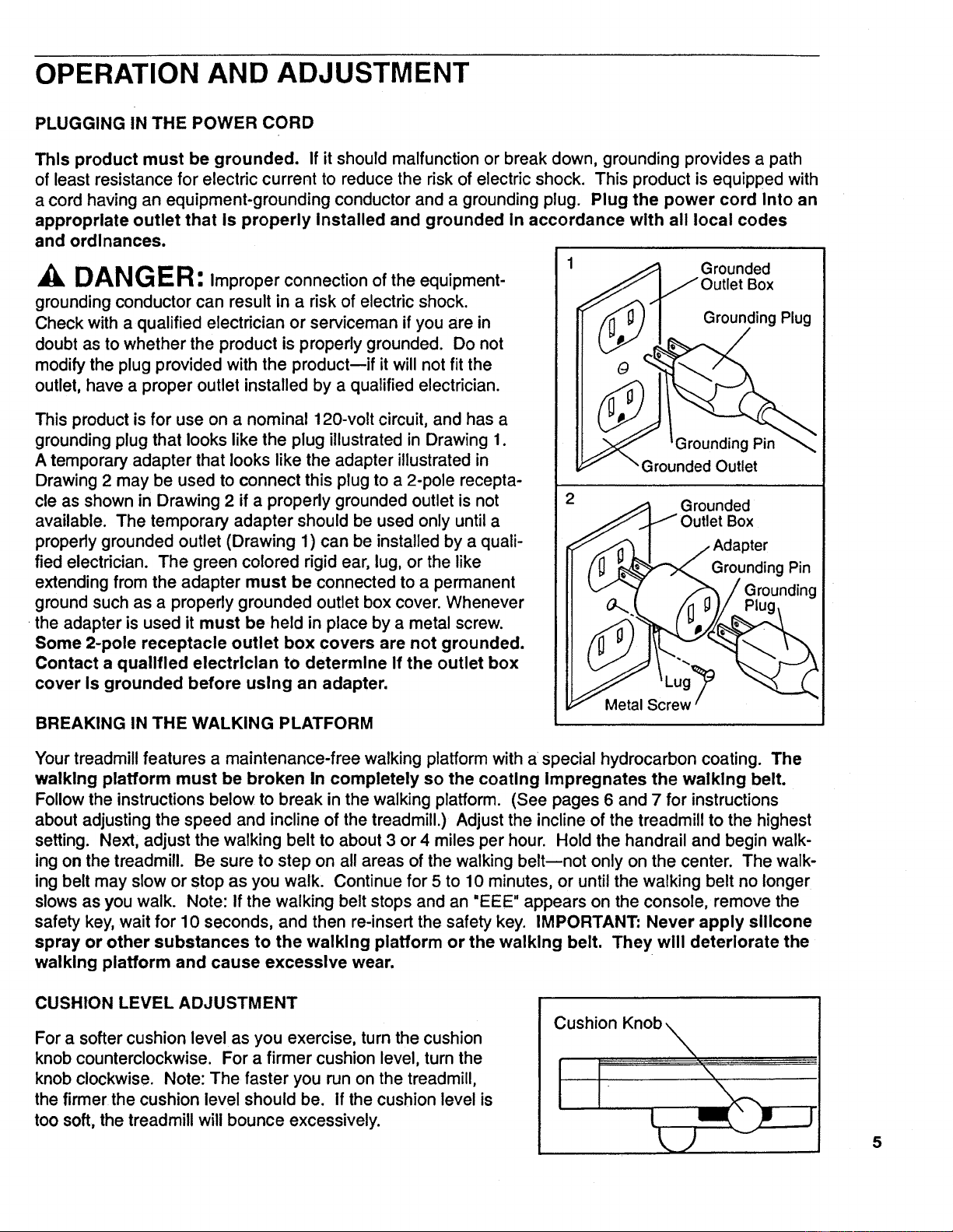
DANG ER: Improper connection of the equipment-
grounding conductor can result in a risk of electric shock.
Check with a qualified electrician or serviceman if you are in
doubt as to whether the product is properly grounded. Do not
modify the plug provided with the product--if it willnot fit the
outlet, have a proper outlet installed by a qualified electrician.
This product is for use on a nominal 120-volt circuit, and has a
grounding plug that looks like the plug illustrated in Drawing 1.
A temporary adapter that looks like the adapter illustrated in
Drawing 2 may be used to connect this plug to a 2-pole recepta-
cle as shown in Drawing 2 if a properly grounded outlet is not
available. The temporary adapter should be used only untila
properly grounded outlet (Drawing 1) can be installed by a quali-
fied electrician. The green colored rigid ear, lug, or the like
extending from the adapter must be connected to a permanent
ground such as a properly grounded outlet box cover. Whenever
the adapter is used it must be held in place by a metal screw.
Some 2-pole receptacle outlet box covers are not grounded.
Contact a qualified electrician to determine If the outlet box
cover is grounded before using an adapter.
BREAKING IN THE WALKING PLATFORM
Grounded
Box
Grounding Plug
Grounding Pin
Grounded Outlet
Grounded
Box
Grounding Pin
Metal Screw
Your treadmill features a maintenance-free walking platform with a special hydrocarbon coating. The
walking platform must be broken In completely so the coating Impregnates the walking belt.
Followthe instructionsbelow to break in the walking platform. (See pages 6 and 7 for instructions
about adjustingthe speed and incline of the treadmill.) Adjust the incline of the treadmill to the highest
setting. Next, adjust the walking belt to about 3 or 4 miles per hour. Hold the handrail and begin walk-
ing on the treadmill. Be sure to step on all areas of the walking belt--not only on the center. The walk-
ing belt may slow or stop as you walk. Continue for 5 to 10 minutes, or until the walking belt no longer
slows as you walk. Note: If the walking belt stops and an "EEE" appears on the console, remove the
safety key, wait for 10 seconds, and then re-insert the safety key. IMPORTANT" Never apply silicone
spray or other substances to the walking platform or the walking belt. They will deteriorate the
walking platform and cause excessive wear.
CUSHION LEVEL ADJUSTMENT
For a softer cushion level as you exercise, turn the cushion
knob counterclockwise. For a firmer cushion level, turn the
knob clockwise. Note: The faster you run on the treadmill,
the firmer the cushion level should be. If the cushion level is
too soft, the treadmill will bounce excessively.
Cushion Knob
J
5
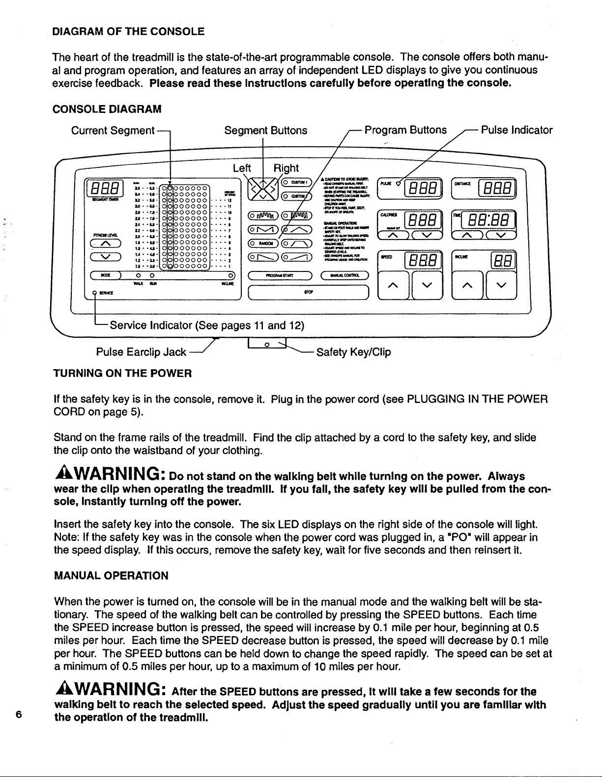
DIAGRAM OF THE CONSOLE
The heart of the treadmill is the state-of-the-art programmable console. The console offers both manu-
al and program operation, and features an array of independent LED displays to give you continuous
exercise feedback. Please read these Instructions carefully before operating the console.
CONSOLE DIAGRAM
C_ SegmentLeft I RiButt°nSght//-- Program..__Butto Pulse Indicator
__/_-_._ f _ f
_.e " "_'" '0 000000 me ..m_ m_/_Mu.
,,..,. oooooo _ _( =__:=.._ _
--- -..ooooooo,....:
=-.u. o ooooooi ..... / ._'_'_.,,...,..
000000 .... . _ ..... .... '
•...,,."'o°oooooo.... , _:__ ..... P'_" _ r_ _._i
•,.-u- o ooo00ol .... , __ _ ,,_,._o,.,_r,ot / lUUU II I I uu.uu I
,-,..-.o ooooool.... , __ _%--'" I,--T-__ _,--_--,
_-_t=m,a. u--_-0 ooo00o l.... , l "_._,?,_,_=,,,=_ 'k J'_ 2k v ,/ r_ 4-., Jk v
,,..,._ oooooo,.... , o_____ .==£=_,?
, u--_- O000001 ....
I_1- -e- O0 0000001 .... I (_) (_
1.2- -u. 0000001 .... I
1.1- -_- 0 0000,00,1 .... I
( _ ) o o ( -,=,,,,=, )
w_x u
[ ..
Service Indicator (See pages 11 and 12)
]
Pulse Earclip Jack --_
J
i o --L....__SafetyKey/Cli p
TURNING ON THE POWER
If the safety key is in the console, remove it. Plug in the power cord (see PLUGGING IN THE POWER
CORD on page 5).
Stand on the frame rails of the treadmill. Find the clip attached by a cord to the safety key, and slide
the clip onto the waistband of your clothing.
kWARNING: Do not stand on the walking belt while turning on the power. Always
wear the clip when operating the treadmill. If you fall, the safety key will be pulled from the con-
sole, Instantly turning off the power.
Insert the safety key into the console. The six LED displays on the right side of the console will light.
Note: If the safety key was in the console when the power cord was plugged in, a "PO" will appear in
the speed display, if this occurs, remove the safety key, wait for five seconds and then reinsert it.
MANUAL OPERATION
6
When the power is turned on, the console will be in the manual mode and the walking beff will be sta-
tionary. The speed of the walking belt can be controlled by pressing the SPEED buttons. Each time
the SPEED increase button is pressed, the speed will increase by 0.1 mile per hour, beginning at 0.5
miles per hour. Each time the SPEED decrease button is pressed, the speed will decrease by 0.1 mile
per hour. The SPEED buttons can be held down to change the speed rapidly. The speed can be set at
a minimum of 0.5 miles per hour, up to a maximum of 10 miles per hour.
WARNING: After the SPEED buttons are pressed, It will take a few seconds for the
walking belt to reach the selected speed. Adjust the speed gradually until you are familiar with
the operation of the treadmill.

Press the SPEED increase button until the walking belt begins to move at slow speed. When the walk-
ing belt begins to move, hold the handrails and step carefully onto the walking belt. Change the speed
of the walking belt as desired by pressing the SPEED buttons. To stop the walking belt, hold down the
SPEED decrease button. The walking belt can be stopped quickly, if desired, by pressing the STOP bar.
To vary the intensity of your exercise, the incline of the treadmill can be changed by pressing the
INCLINE buttons. Each time the INCLINE increase button is pressed, the incline will increase by 0.5%.
Each time the INCLINE decrease button is pressed, the incline will decrease by 0.5%. The INCLINE
buttons can be held down to change the incline rapidly. The incline can be set at a minimum of 1%, up
to a maximum of 12%. Note: After the INCLINE buttons are pressed, it will take a few seconds for the
treadmill to reach the selected incline.
PROGRAM OPERATION
In the program mode, the console willautomatically controleither the speed or the incline of the treadmill.
The console offers a selection of preset programs, each designed to guide you through a different type
of workout. In addition, you can create custom programs, and save them in memory for future workouts.
CREATING A CUSTOM PROGRAM
Press the CUSTOM 1 or CUSTOM 2 button. The indicatoron the button you press will light.
Next, press the MODE button to select the WALK, RUN or INCLINE mode. An indicator will light to
show which mode you have selected. If you select the WALK mode, the speed range of the treadmill
will be 1.0 mile per hour to 3.6 miles per hour during the program. If you select the RUN mode, the
speed range of the treadmill will be 3.0 miles per hour to 9.5 miles per hour during the program. If you
select the INCLINE mode, the incline range of the treadmill will be 1% to 12% during the program.
All programs are divided intotwenty equal time periods, called segments. If the WALK or RUN mode was
selected, a speed settingshould now be programmedfor each of thetwenty segments. If the INCLINE
mode was selected, an inclinesetting shouldnow be programmedfor each of the twenty segments. The
segments are displayedin the vertical columnsof indicatorson the left side of the console. Seven seg-
ments are displayed at a time--the first segment is displayedin the CURRENT SEGMENT column, and
the next six segments are displayed in the columnsto the rightof the CURRENT SEGMENT column.
(See the paragraph below for an explanation of the columnto the leftof the CURRENT SEGMENT col-
umn.) Toprogram a setting for the first segment, displayed in the CURRENT SEGMENT column, press
the SEGMENT increase or decrease button. Each time the SEGMENT increase buttonis pressed, an
additionalindicatorwilllight. Each time the SEGMENT decrease buttonis pressed, an additional indicator
willdarken. The M.P.H. scales or the PERCENT OF GRADE scale will show the setting you have pro-
grammed. After you have programmed a settingfor the first segment, press the SEGMENT left button.
All segments will move one column to the left--the first segment will disappear, the second segment will
be displayed in the CURRENT SEGMENT column,and the next sixsegments willbe displayed in the
columns to the rightof the CURRENT SEGMENT column. Program a setting for the second segment as
described above. Repeat untilyou have programmed a settingfor each ofthe twenty segments.
The lighted indicators in the column to the leftof the CURRENT SEGMENT column show the range of
settings you have programmedmthe lower indicatorshowsthe lowest setting, and the upper indicator
shows the highest setting. If desired, the difficultylevel of the program can be increased or decreased
by pressing the FITNESS LEVEL buttons. If the WALK mode was selected, the speed settings of all
segments willchange by 0.2 miles per hour each time one of the buttons is pressed. Ifthe RUN mode
was selected, the speed settings of all segments will change by 0.5 miles per hour each time one of the
buttons is pressed. If the INCLINE mode was selected, the incline settings of all segments willchange
by 1% each time one of the buttons is pressed. Note: The difficultylevel of the program can be
increased or decreased only untilthe upper or lower indicatorreaches the top or bottom of the column.
7

Next, set the length of time you want the program to last by pressing the TIME buttons. The length of
time will be displayed in the TIME display. Each time one of the buttons is pressed, the length of time
will change by twenty seconds. The buttons can be held down to change the length of time rapidly.
The program can be set to last for a minimum of 5 minutes, up to a maximum of 80 minutes. (The
length of time each segment willlast will be displayed in the SEGMENT TIMER display. Each segment
will last for 1/20 of the length of time shown in the TIME display.)
To start the program, press the PROGRAM START button. The first segment will be displayed in the
CURRENT SEGMENT column, and the treadmill will automatically adjust to the first speed or incline
setting. Hold the handrails, step carefully onto the walking belt and begin exercising. The time remain-
ing in the first segment will be shown in the SEGMENT TIMER display. When no time remains, all seg-
ments will move one column to the left--the first segment will disappear, the second segment will be
displayed in the CURRENT SEGMENT column, and the treadmill will automatically adjust to the sec-
ond setting. The program will continue in this manner until all twenty segments have been displayed.
A tone will then sound, the walking belt will slow to a stop and the program will be completed. (If the
WALK or RUN mode was selected, the incline can be controlled during the program by pressing the
INCLINE buttons. If the INCLINE mode was selected, the walking belt will begin to move at 1.0 mile
per hour when the program is started. The speed of the walking belt can be controlled during the pro-
gram by pressing the SPEED buttons.)
While the program is running, the setting of the current segment can be changed, if desired, by pressing
the SEGMENT increase and decrease buttons. If desired, the difficulty level of the entire program can
be changed by pressing the FITNESS LEVEL buttons. The length of time the program will last can be
changed by pressing the TIME buttons. To stop the program before the program has ended, press the
STOP bar. The console will then be in the same state as if the program had been completed.
When the program is completed, a different program can be selected or the console can be switched to
the manual mode by pressing the MANUAL CONTROL button. The current settings of the program will
be saved in memory. The settings will be saved in memory even when the power cord is unplugged.
SELECTING A PRESET PROGRAM
Press one of the eight PROGRAM buttons. The indicator on the button you press will light.
Next, press the MODE button to select the WALK, RUN or INCLINE mode. An indicator will light to
show which mode you have selected.
The speed or incline settings of the selected program will be displayed in the vertical columns of indica-
tors on the left side of the console. Seven segments are displayed at a time. If desired, the setting of
any segment can be changed. Press the SEGMENT left or right button until the segment you want to
change is displayed in the CURRENT SEGMENT column. Press the SEGMENT increase or decrease
buttons to change the setting of the segment.
Ifdesired, the difficulty level of the program can be increased or decreased by pressing the FITNESS
LEVEL buttons. This is done in the same manner as for a custom program.
Next, set the length of time you want the program to last by pressing the TIME buttons. This is done in
the same manner as for a custom program.
8
To start the program, press the PROGRAM START button. The program will run in exactly the same
manner as a custom program. When the program is completed, a different program can be selected or
the console can be switched to the manual mode by pressing the MANUAL CONTROL button.
Although the settings of a preset program can be changed, only the original program settings will be
saved in memory.
OPERATING THE MONITOR MODES
PULSE: To use the pulse mode of the console, the pulse earclip must be plugged into the pulse jack.
Attach the earclip to your left ear lobe and slide the metal clothes clip onto your collar. When your
pulse is detected, the PULSE indicator will flash with each heartbeat. After a few seconds, your pulse
will be shown in the PULSE display. If your pulse is not shown, rub your ear lobe and reposition the
earclip. It may be helpful to stand still while measuring your pulse.
DISTANCE: The DISTANCE display will show the total distance you have walked or run, in miles.
CALORIE: For an accurate measurement of your Calorie expenditure, your weight should be entered
into the console. To enter your weight, press !he WEIGHT SET buttons. Each time one of the buttons
is pressed, the weight displayed will increase or decrease by 1 pound. The buttons can be held down
to enter your weight quickly.
TIME: When the console is in the manual mode, the TIME display will show the total time that you
have walked or run during your workout, up to 99 minutes and 59 seconds. (If the treadmill is run for
more than 99 minutes and 59 seconds, the walking belt will automatically slow to a stop. This safety
feature prevents the treadmill from being left running for long periods of time.) If desired, a time goal
can be set. Press the TIME buttons to set the length of time that you plan to exercise. Each time one
of the buttons is pressed, the length of time displayed will change by ten seconds. The buttons can be
held down to set a time goal quickly. A time goat can be set for a minimum of 10 seconds, up to a
maximum of 99 minutes and 50 seconds. As you exercise, the time will be counted down. When the
time goal is completed, a tone will sound and the walking belt will slow to a stop.
When the console is in the program mode, a time goal will be set and the console will count the time
down. When the program is completed, a tone will sound and the walking belt will slow to a stop.
TURNING THE POWER OFF
To turn the power off, remove the safety key from the console. All displays and indicators will darken.
Store the safety key in a secure location.
INFORMATION MODE
The console features an information mode to let you keep track of trip time and distance, as well as the
total time and distance accumulated on the treadmill. To select the information mode, hold down the
STOP bar while inserting the safety key into the console.
When the information mode is selected, the time display will show the trip time, up to 9,999 hours. The
distance and pulse displays together will show the trip distance, up to 99,999 miles. The incline display
will show a service code. Service code "SO" indicates that no routine service is needed. Service code
"$1" or "$3" indicates that service is needed (see 6. a. and b. on pages 11 and 12). While the trip time
and distance are displayed, they can be reset to zero by pressing the TIME decrease button.
To view the total time and distance, press the TIME increase button. The time display will show the total
time, up to 9,999 hours. The distance and pulse displays together will show the total distance, up to
99,999 miles.
To exit the information mode, remove the safety key.
9
TROUBLE-SHOOTING AND STORAGE
Most treadmill problems can be solved by following the simple steps below. Find the symptom
that applies to your treadmill and follow the steps listed. If further assistance is needed, please call our
Customer Service Department toll-free at 1-800-999-3756, Monday through Friday, 6 a.m. until 6 p.m.
Mountain Time (excluding holidays).
1. SYMPTOM: THE POWER DOES NOT TURN ON
a. Make sure that the power cord is plugged into a properly grounded outlet. (See OPERATION
AND ADJUSTMENT in this manual.) If an extension cord is needed, use only a 14-gauge gener-
al-purpose cord of five feet or less in length.
b. After the power cord has been plugged in, make sure that the safety key is fully inserted into the
console. Various indicators on the console should light. (See OPERATION AND ADJUSTMENT
in this manual.)
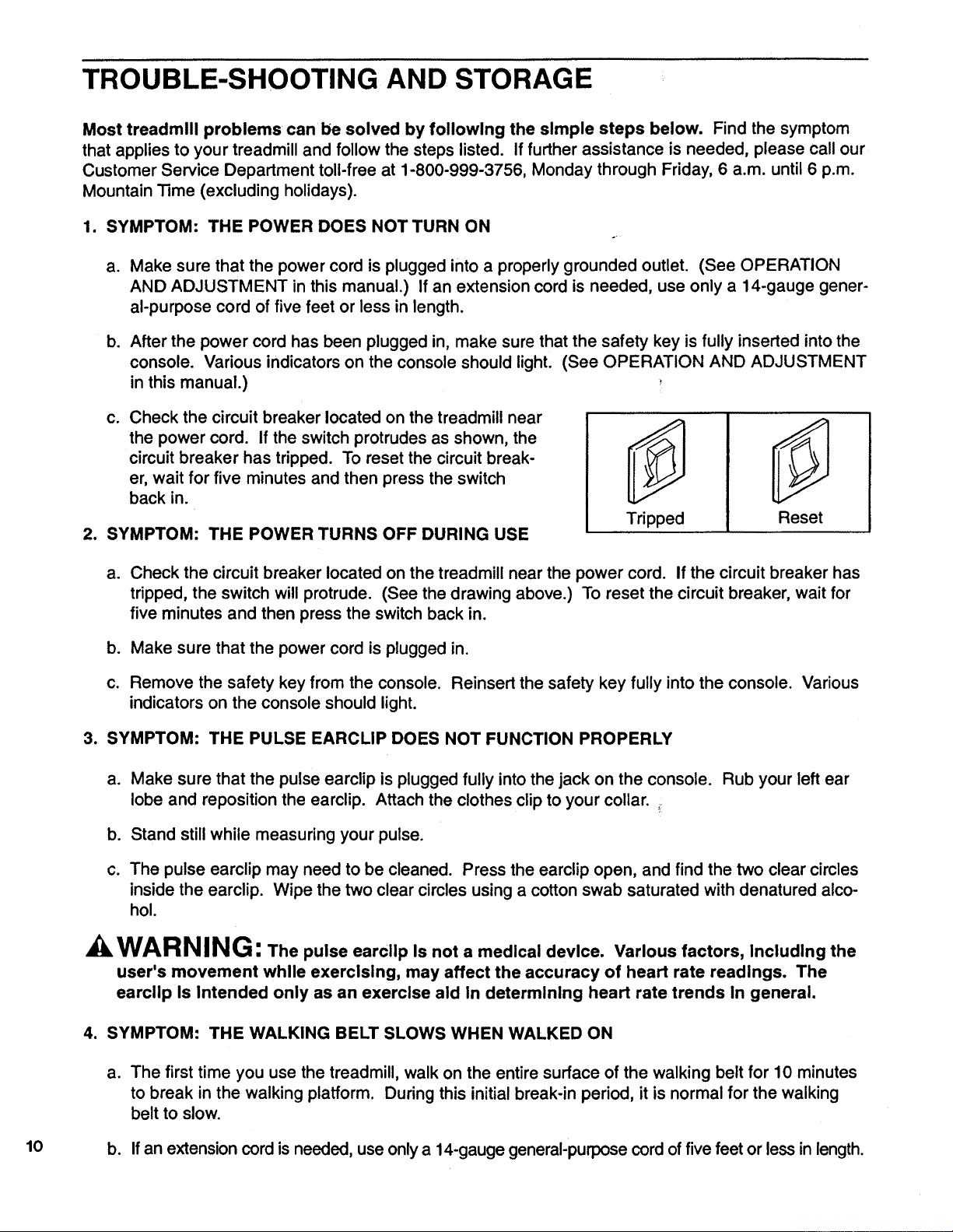
C. Check the circuit breaker located on the treadmill near
the power cord. if the switch protrudes as shown, the
circuit breaker has tripped. To reset the circuit break-
er, wait for five minutes and then press the switch
back in.
2. SYMPTOM: THE POWER TURNS OFF DURING USE
Tripped
Reset
a. Check the circuit breaker located on the treadmill near the power cord. If the circuitbreaker has
tripped, the switch will protrude. (See the drawing above.) To reset the circuit breaker, wait for
five minutes and then press the switchback in.
b. Make sure that the power cord is plugged in.
c. Remove the safety key from the console. Reinsert the safety key fully into the console. Various
indicators on the console should light.
3. SYMPTOM: THE PULSE EARCLIP DOES NOT FUNCTION PROPERLY
a.
Make sure that the pulse earclip is plugged fully into the jack on the console. Rub your left ear
lobe and reposition the earclip. Attach the clothes clip to your collar.
b. Stand still while measuring your pulse.
c. The pulse earclip may need to be cleaned. Press the earclip open, and find the two clear circles
inside the earclip. Wipe the two clear circles using a cottonswab saturated with denatured alco-
hol.
WARNING: The pulse earcllp Is not a medical device. Various factors, Including the
user's movement while exercising, may affect the accuracy of heart rate readings. The
earciip Is Intended only as an exercise aid in determining heart rate trends In general.
4. SYMPTOM: THE WALKING BELT SLOWS WHEN WALKED ON
a. The first time you use the treadmill, walk on the entire surface of the walking belt for 10 minutes
to break in the walking platform. During this initial break-in period, it is normal for the walking
belt to slow.
10 b. If an extension cordis needed, use onlya 14-gauge general-purpose cord offivefeet or lessin length.
C,
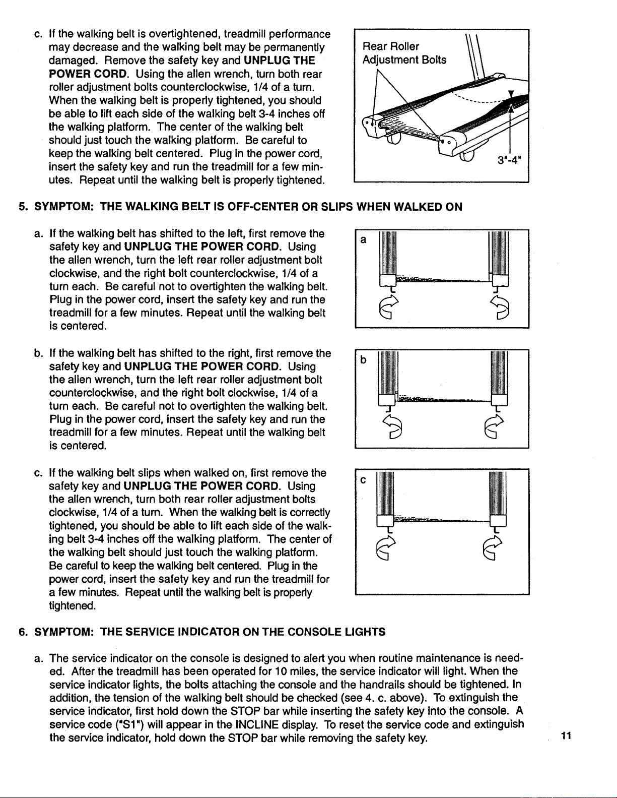
If the walking belt is overtightened, treadmill performance
may decrease and the walking belt may be permanently
damaged. Remove the safety key and UNPLUG THE
POWER CORD. Using the allen wrench, turn both rear
roller adjustment bolts counterclockwise, 1/4 of a turn.
When the walking belt is properly tightened, you should
be able to lift each side of the walking belt 3-4 inches off
the walking platform. The center of the walking belt
should just touch the walking platform. Be careful to
keep the walking belt centered. Plug in the power cord,
insert the safety key and run the treadmill for a few min-
utes. Repeat until the walking belt is properly tightened.
Rear Roller
Adjustment Bolts
5. SYMPTOM: THE WALKING BELT IS OFF-CENTER OR SLIPS WHEN WALKED ON
a.
If the walking belt has shifted to the left, first remove the
safety key and UNPLUG THE POWER CORD. Using
the allen wrench, turn the left rear roller adjustment bolt
clockwise, and the right bolt counterclockwise, 1/4 of a
turn each. Be careful not to overtighten the walking belt.
Plug in the power cord, insert the safety key and run the
treadmill for a few minutes. Repeat until the walking belt
is centered.
b.
If the walking belt has shifted to the right, first remove the
safety key and UNPLUG THE POWER CORD. Using
the allen wrench, turn the left rear roller adjustment bolt
counterclockwise, and the rightbolt clockwise, 1/4 of a
turn each. Be careful not to overtighten the walking belt.
Plug in the power cord, insert the safety key and run the
treadmill for a few minutes. Repeat until the walking belt
is centered.
b
Co
If the walking belt slips when walked on, first remove the
safety key and UNPLUG THE POWER CORD. Using
the allen wrench, turn both rear roller adjustment bolts
clockwise, 1/4 of a turn. When the walking belt iscorrectly
tightened, you should be able to lifteach side of the walk-
ing belt 3-4 inches off the walking platform. The center of
the walking belt should just touch the walking platform.
Be carefulto keep the walking belt centered. Plug in the
power cord, insert the safety key and runthe treadmill for
a few minutes. Repeat untilthe walking belt isproperly
tightened.
6. SYMPTOM: THE SERVICE INDICATOR ON THE CONSOLE LIGHTS
ao
The service indicator on the console is designed to alert you when routine maintenance is need-
ed. After the treadmill has been operated for 10 miles, the service indicator will light. When the
service indicator lights, the bolts attaching the console and the handrails should be tightened. In
addition, the tension of the walking belt should be checked (see 4. c. above). To extinguish the
service indicator, first hold down the STOP bar while inserting the safety key into the console. A
service code ("$1 ") will appear in the INCLINE display. To reset the service code and extinguish
the service indicator, hold down the STOP bar while removing the safety key.
11
b°
After the treadmill has been operated for 600 miles, the service indicator will again light. When
the service indicator lights, the tension of the walking belt should be 0_ecked (see 4. c. above).
In addition, a service technician should check the amp draw and the motor brushes. For service,
see the back cover of the owner's manual. To extinguish the service indicator, first hold down
the STOP bar while inserting the safety key into the console. A service code ("$3") will appear in
the INCLINE display. To reset the service code and extinguish the service indicator, hold down
the STOP bar while removing the safety key.
7. SYMPTOM: THE CONSOLE DOES NOT FUNCTION PROPERLY
a. If a console malfunction occurs, an error code ("PO" or "EEE") may appear on the display. If an
error code appears, remove the safety key, wait for ten seconds and then reinsert the safety key.
if the error code appears again, call our Customer Service Department. Do not operate the
treadmill until the problem is corrected.
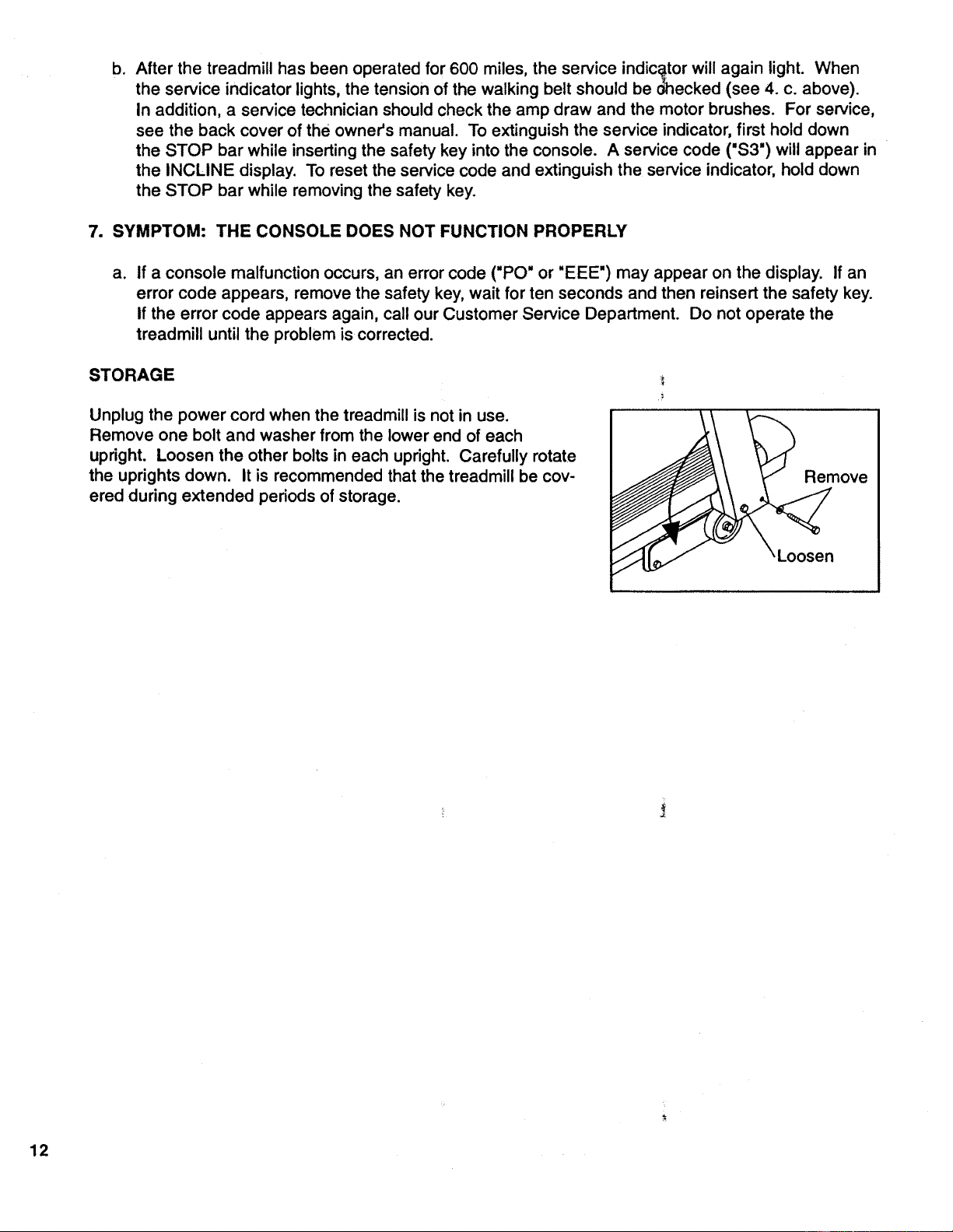
STORAGE
Unplug the power cord when the treadmill is not in use.
Remove one bolt and washer from the lower end of each
upright. Loosen the other bolts in each upright. Carefully rotate
the uprights down. It is recommended that the treadmill be cov-
ered duringextended periods of storage.
/;
Remove
Loosen
12
CONDITIONING GUIDELINES
The following guidelines will help you to plan your exercise program. Remember that proper nutrition
and adequate rest are essential for successful results.
kWARNING" Before beginning this or any exercise program, consult your physician.
This Is especially Important for Individuals over the age of 35 or Individuals with pre-existing
health problems.
EXERCISE INTENSITY
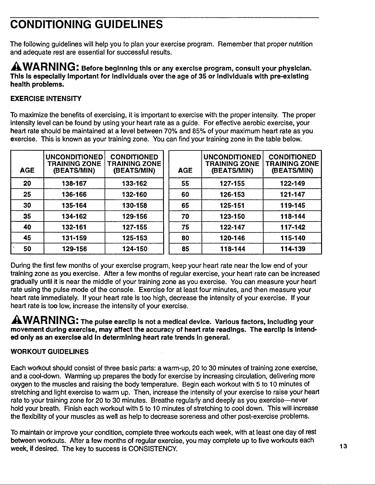
To maximize the benefits of exercising, it is importantto exercise with the proper intensity. The proper
intensitylevel can be found by using your heart rate as a guide. For effective aerobic exercise, your
heart rate should be maintained at a level between 70% and 85% of your maximum heart rate as you
exercise. This is known as your training zone. You can find your training zone in the table below.
AGE
20
25
30
35
40
45
50
I UNCONDITIONED
TRAINING ZONE
(BEATS/MIN)
138-167
136-166
135-164
134-162
132-161
131-159
129-156
CONDITIONED
TRAINING ZONE
_EATS/MIN)
133-162
132-160
130-158
129-156
127-155
125-153
124-150
AGE
55
60
65
70
75
80
85
UNCONDITIONED
TRAINING ZONE
(BEATSIMIN)
127-155
126-153
125-151
123-150
122-147
120-146
118-144
CONDITIONED
TRAINING ZONE
(BEATS/MIN)
122-149
121-147
119-145
118-144
117-142
115-140
114-139
During the first few months of your exercise program, keep your heart rate near the low end of your
training zone as you exercise. After a few months of regular exercise, your heart rate can be increased
gradually until it is near the middle of your training zone as you exercise. You can measure your heart
rate using the pulse mode of the console. Exercise for at least four minutes, and then measure your
heart rate immediately. If your heart rate is too high, decrease the intensity of your exercise. If your
heart rate is too low, increase the intensity of your exercise.
kWARNING: The pulse earcllp Is not a medical device. Various factors, Including your
movement during exercise, may affect the accuracy of heart rate readings. The earcllp Is Intend-
ed only as an exercise aid In determinlng heart rate trends in general.
WORKOUT GUIDELINES
Each workout should consist of three basic parts: a warm-up, 20 to 30 minutes of training zone exercise,
and a cool-down. Warming up prepares the body for exercise by increasing circulation, delivering more
oxygen to the muscles and raising the body temperature. Begin each workout with 5 to 10 minutes of
stretching and light exercise to warm up. Then, increase the intensity of your exercise to raise your heart
rate to your training zone for 20 to 30 minutes. Breathe regularly and deeply as you exercise--never
hold your breath. Finish each workout with 5 to 10 minutes of stretching to cool down. This will increase
the flexibility of your muscles as well as help to decrease soreness and other post-exercise problems.
To maintain or improve your condition, complete three workouts each week, with at least one day of rest
between workouts. After a few months of regular exercise, you may complete up to five workouts each
week, if desired. The key to success is CONSISTENCY.
13
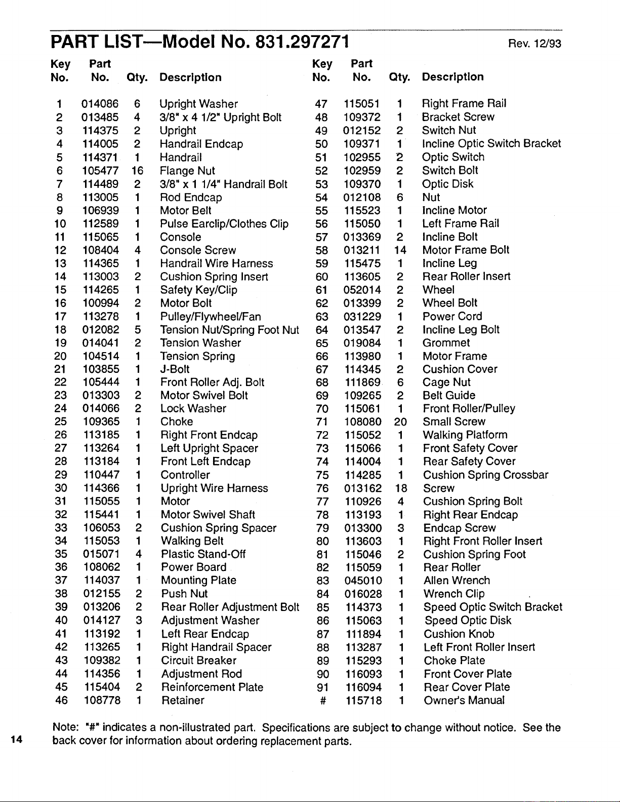
PART LISTmModel No. 831.297271
Key Part Key
No. No. Qty. Description No.
Part
No. Qty. Description
Rev. 12/93
1 014086 6 Upright Washer 47 115051 1 Right Frame Rail
2 013485 4 3/8" x 4 1/2" Upright Bolt 48 109372 1 Bracket Screw
3 114375 2 Upright 49 012152 2 Switch Nut
4 114005 2 Handrail Endcap 50 109371 1 Incline Optic Switch Bracket
5 114371 1 Handrail 51 102955 2 Optic Switch
6 105477 16 Flange Nut 52 102959 2 Switch Bolt
7 114489 2 3/8" x 1 1/4" Handrail Bolt 53 109370 1 Optic Disk
8 113005 1 Rod Endcap 54 012108 6 Nut
9 106939 1 Motor Belt 55 115523 1 Incline Motor
10 112589 1 Pulse Earclip/Clothes Clip 56 115050 1 Left Frame Rail
11 115065 1 Console 57 013369 2 Incline Bolt
12 108404 4 Console Screw 58 013211 14 Motor Frame Bolt
13 114365 1 Handrail Wire Harness 59 115475 1 Incline Leg
14 113003 2 Cushion Spring Insert 60 113605 2 Rear Roller Insert
15 114265 1 Safety Key/Clip 61 052014 2 Wheel
16 100994 2 Motor Bolt 62 013399 2 Wheel Bolt
17 113278 1 Pulley/Flywheel/Fan 63 031229 1 Power Cord
18 012082 5 Tension Nut/Spring Foot Nut 64 013547 2 Incline Leg Bolt
19 014041 2 Tension Washer 65 019084 1 Grommet
20 104514 1 Tension Sp ring 66 113980 1 Motor Frame
21 103855 1 J-Bolt 67 114345 2 Cushion Cover
22 105444 1 Front Roller Adj. Bolt 68 111869 6 Cage Nut
23 013303 2 Motor Swivel Bolt 69 109265 2 Belt Guide
24 014066 2 Lock Washer 70 115061 1 Front Roller/Pulley
25 109365 1 Choke 71 108080 20 Small Screw
26 113185 1 Right Front Endcap 72 115052 1 Walking Platform
27 113264 1 Left Upright Spacer 73 115066 1 Front Safety Cover
28 113184 1 Front Left Endcap 74 114004 1 Rear Safety Cover
29 110447 1 Controller 75 114285 1 Cushion Spring Crossbar
30 114366 1 Upright Wire Harness 76 013162 18 Screw
31 115055 1 Motor 77 110926 4 Cushion Spring Bolt
32 115441 1 Motor Swivel Shaft 78 113193 1 Right Rear Endcap
33 106053 2 Cushion Spring Spacer 79 013300 3 Endcap Screw
34 115053 1 Walking Belt 80 113603 1 Right Front Roller Insert
35 015071 4 Plastic Stand-Off 81 115046 2 Cushion Spring Foot
36 108062 1 Power Board 82 115059 1 Rear Roller
37 114037 1 Mounting Plate 83 045010 1 Allen Wrench
38 012155 2 Push Nut 84 016028 1 Wrench Clip
39 013206 2 Rear Roller Adjustment Bolt 85 114373 1 Speed Optic Switch Bracket
40 014127 3 Adjustment Washer 86 115063 1 Speed Optic Disk
41 113192 1 Left Rear Endcap 87 111894 1 Cushion Knob
42 113265 1 Right Handrail Spacer 88 113287 1 Left Front Roller Insert
43 109382 1 Circuit Breaker 89 115293 1 Choke Plate
44 114356 1 Adjustment Rod 90 116093 1 Front Cover Plate
45 115404 2 Reinforcement Plate 91 116094 1 Rear Cover Plate
46 108778 1 Retainer # 115718 1 Owner's Manual
14
Note: "#" indicates a non'illustrated part. Specifications are subject to change without notice. See the
back cover for information about ordering replacement parts.
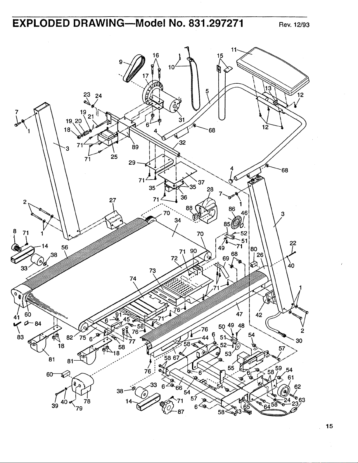
EXPLODED DRAWING--Model No. 831.297271 aev.12/93
41 60
83
23 24
19
56
71 25
27
16 15
31
89
I
74
7O
73
72
71
'6
57
1
86
68
3
22
40
12
63
54
61
62
15
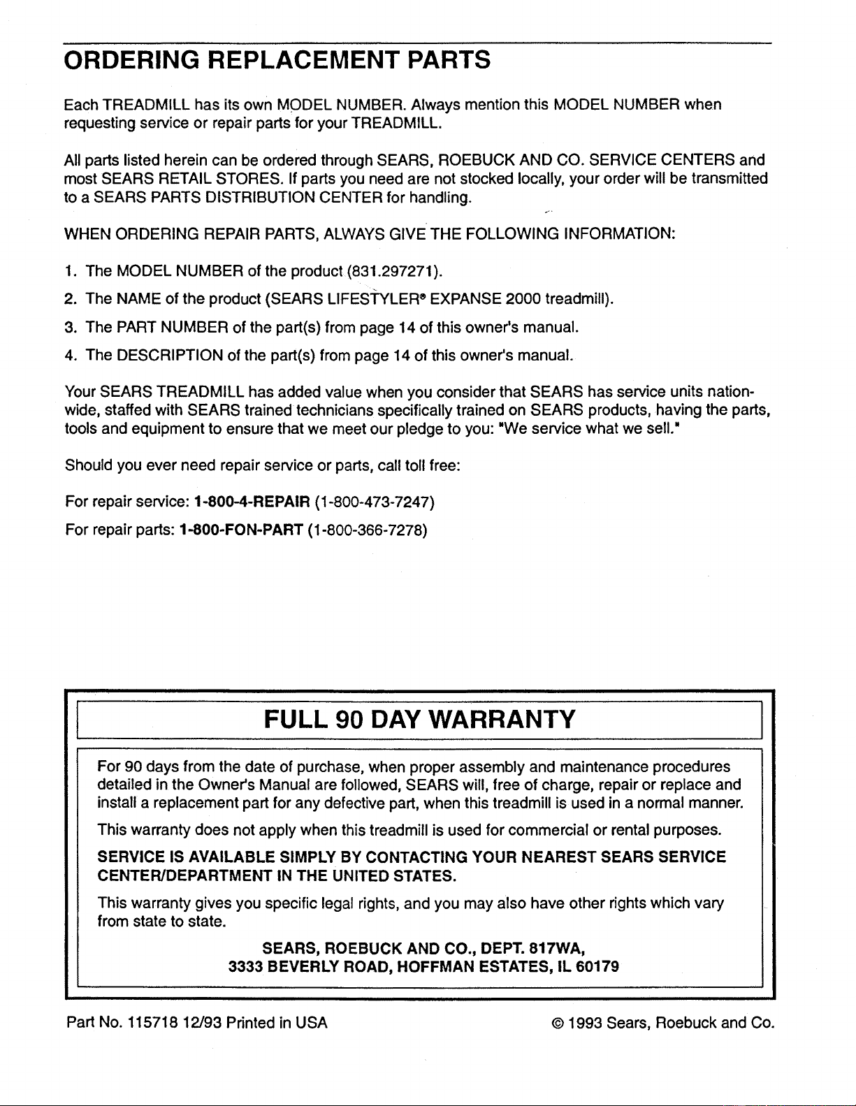
ORDERING REPLACEMENT PARTS
Each TREADMILL has its own MODEL NUMBER. Always mention this MODEL NUMBER when
requesting service or repair parts for your TREADMILL.
All parts listed herein can be ordered through SEARS, ROEBUCK AND CO. SERVICE CENTERS and
most SEARS RETAIL STORES. If parts you need are not stocked locally, your order will be transmitted
to a SEARS PARTS DISTRIBUTION CENTER for handling.
r.,
WHEN ORDERING REPAIR PARTS, ALWAYS GIVE THE FOLLOWING INFORMATION:
1. The MODEL NUMBER of the product (831.297271).
2. The NAME of the product (SEARS LIFES'I'YLER _EXPANSE 2000 treadmill).
3. The PART NUMBER of the part(s) from page 14 of this owner's manual.
4. The DESCRIPTION of the part(s) from page 14 of this owner's manual.
Your SEARS TREADMILL has added value when you consider that SEARS has service units nation-
wide, staffed with SEARS trained technicians specifically trained on SEARS products, having the parts,
tools and equipment to ensure that we meet our pledge to you: "We service what we sell."
Should you ever need repair service or parts, call toll free:
For repair service: 1-800-4-REPAIR (1-800-473-7247)
For repair parts: 1-800-FON-PART (1-800-366-7278)
FULL 90 DAY WARRANTY
For 90 days from the date of purchase, when proper assembly and maintenance procedures
detailed in the Owner's Manual are followed, SEARS will, free of charge, repair or replace and
installa replacement part for any defective part, when this treadmill is used in a normal manner.
This warranty does not apply when this treadmill is used for commercial or rental purposes.
SERVICE IS AVAILABLE SIMPLY BY CONTACTING YOUR NEAREST SEARS SERVICE
CENTER/DEPARTMENT IN THE UNITED STATES.
This warranty gives you specific legal rights, and you may also have other rights which vary
from state to state.
SEARS, ROEBUCK AND CO., DEPT. 817WA,
3333 BEVERLY ROAD, HOFFMAN ESTATES, IL 60179
Part No. 115718 12/93 Printed in USA © 1993 Seam, Roebuck and Co.