Loading ...
Loading ...
Loading ...
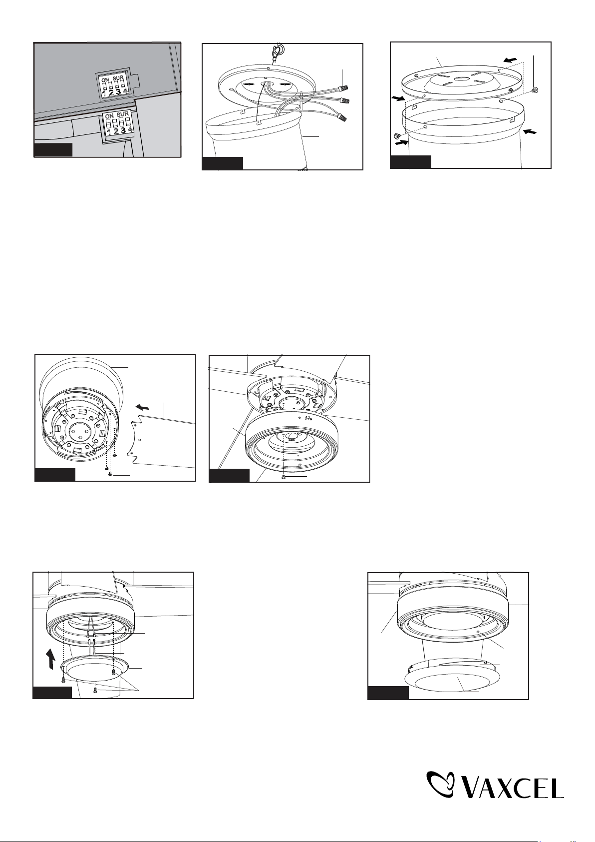
Make wire connections:
1). The white motor wire to the
white wire from the outlet box
with a wire connector.
2). The black motor wire to the
black wire from the outlet box
with a wire connector.
3).The ground wire from the
outlet box to the ground
wire from the mounting
plate with a wire connector.
PAGE: 6 / 8
There are four mounting plate screws
and lock washers. Remove two screws
and lock washers from the mounting
plate (one from each side) and loosen
the other two remaining screws. Align
the “L shaped” slots of the canopy
with the two remaining screws on the
mounting plate and push the motor
assembly upwards to engage the slots
and turn clockwise to lock in place.
Tighten the screws and install the other
two mounting plate screws and lock
washers into the remaining holes of
the canopy and tighten.
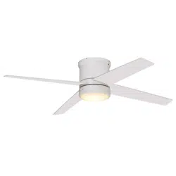
Insert the fan blade through the slot
on the fan motor assembly and
fasten fan blade to the fan motor
assembly with screws. Repeat for
remaining fan blades.
Attach the glass shade to the connect
plate of light kit by aligning studs and
slots, and then turn it clockwise until it
is locked in place.
Remove three screws from
connect plate of light kit first.
Then connect the female
terminals from fan motor
assembly to male terminals
from LED module. Connect
the white (neutral) wire from
the light kit to white(neutral)
wire from connect plate of
light kit; connect the blue
(hot) wire from light kit to
Fan Blade
Fig.9
Blade Screw
Fan Motor
Assembly
Fig.12
Code example:
1-ON 2-OFF 3-ON 4-OFF on
both SUR Switches.
Note: If you have two ceiling fans
with 2 remote control units, set 2
different codes for each set of
transmitter / receivers.
Fig.6b
Remove one screw and loosen another
two screws from fan motor assembly first,
then thread the fan motor assembly wires
through connect plate of light kit, then
push the connect plate of light kit upwards
until the fan motor assembly screws insert
into the key hole slots of connect plate of
light kit, then rotate the connect plate of
light kit until it’s fixed on the fan motor
assembly bottom. Finally, secure the
connect plate of light kit to the fan motor
assembly bottom with previous screw
which was removed. Tighten the other
two fan motor assembly screws.
Wire Connector
Fig.7
Fan Motor
Assembly
Mounting Plate
Mounting Screw
Fig.8
Fan Motor Assembly
Fig.11
Male Connector
Female
Connector
LED Module
Screw
blue (hot) wire from connect plate of light kit. Carefully put the
wires into the connect plate of light kit, then attach the light kit
onto the connect plate of light kit with the connect plate screws.
Glass Shade
Slot
Stud
Connect
Plate of
Light Kit
Fan Motor
Assembly
Fix Screw
Connect
Plate of
Light Kit
Fig.10
220407
Loading ...
Loading ...