Livewire 4
User’s Guide
What’s Inside
1. Livewire 4
2. Wire
1
2
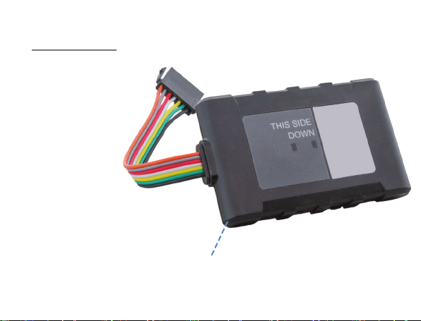
Livewire 4 Wiring Diagram Wiring Key
Pin Wire Color Discription
7 Black Ground
6 Green Output 2
5 Yellow Output 1/Input
4 White Ignition Detection
3 Red 12v Power Input
2 Gray TXD
1 Orange RXD
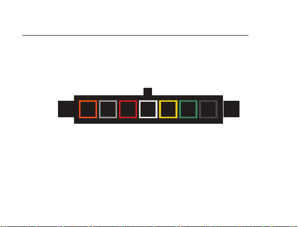
Livewire 4 Wiring Diagram Pin Layout From Device
1 2 3 4 5 6 7
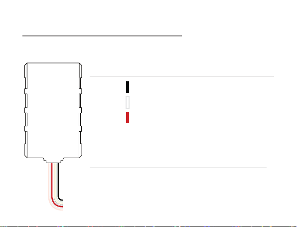
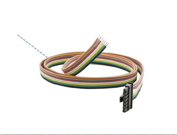
Livewire 4 Wiring (Basic Installation)
Just three wires are needed for this installation.
Pin Wire Color Connection
7 Black Run to Ground
4 White Run to Iginition
3 Red Run to 12v Power
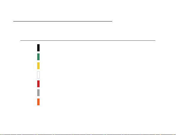
Notes on TXD and RXD (Advanced Installation)
TXD signal is an output on a DTE device and an input on a
DCE device. Similarly, RXD is an output on a DCE device and
input on a DTE device.
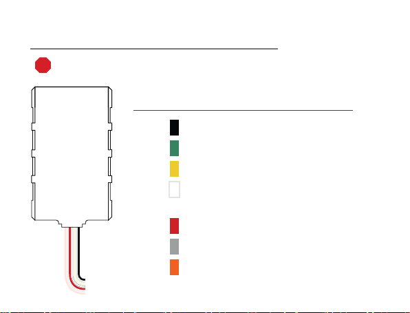
Livewire 4 Wiring (Advanced Installation)
STOP - Advanced installation not required for regular GPS tracking.
Please contact us before attempting any custom installations.
Pin Wire Color Connection
7 Black Run to Ground
6 Green Output 2
5 Yellow Output 1/Input
4 White Run to Ignition
(Connect to Run Part)
3 Red Run to 12v Power
2 Gray TXD
1 Orange RXD

Getting Started
If you purchased your device pre-activated you should have already
received an email containing your default login information before the
device arrived.
If you did not purchase a pre-activated tracker, please visit activate.
brickhousesecurity.com to complete your device activation.
Installation of the Livewire 4 is similar to that of a car stereo. If you are
not condent in your ability to install the device, we suggest that you
contact a local car stereo/alarm installer. The Livewire 4 is powered by your
vehicle; to install the device, connect the wiring harness to the base unit as
indicated in the diagram above. Once that’s done, connect the Red wire to
the vehicle’s power. Connect the Black wire to Ground. Connect the White
wire to the vehicle’s ignition or accessory power.
The Livewire 4 features an internal antenna which is needed to ensure
GPS communication. When installing the unit in the dash of the vehicle,
place the unit with the lights and logo facing down with as little metallic
obstruction above it as possible. Because of dierences in vehicle

manufacturers, best placement will vary by vehicle. If signal strength seems
to be weak, move the device to a dierent position and check the platform
to see if the device has connected and is reporting.
Once the unit has been installed, take the car for a drive for 15-20 minutes
so the device can register on the GPS network and begin reporting. The
Livewire 4 is motion activated; it will only attempt to communicate with the
platform when motion is detected, which will update the tracker’s position
on the map.
The Red and Green LEDs on the label side of the device are intended to
help you troubleshoot problems with your tracker. When the car’s ignition is
rst turned on, the device will power up. The GPS Light (RED) should begin
to ash followed by the Cell Light (GREEN). The GPS Light will turn solid
once a GPS signal is located. The Cell Light will slow down, but remain
ashing once it has connected to the cellular network.
The Red and Green LEDs on the back panel of the device are intended to
help you troubleshoot problems with your Livewire. When the car’s ignition
is rst turned on, the device will power up. The Green LED will show solid
for approximately 30 seconds (there may be some brief ickers initially

while the processor initializes). At no other time should the Green LED
remain solid for such a long period.
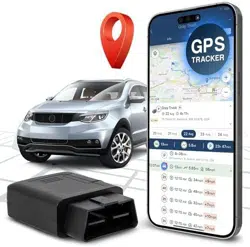
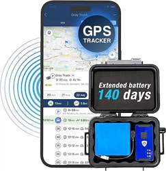
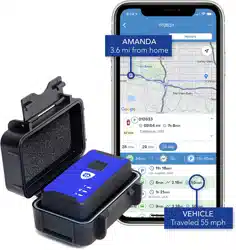
Tracking Your Device
By default, the Livewire 4 reports every 1 minute when your car ignition is
turned on/while the vehicle is moving and will report every hour when the
ignition is o.
If you plan on tracking a vehicle that will remain idle for extended periods
of time, we recommend unplugging the Livewire 4 to alleviate any risk of
draining the car’s battery.
To track your Livewire 4, open a browser window and go to
http://BrickHouseSecurity.com. Hover your cursor over the Login tab on
the top right of the website and click on GPS Tracking. Enter your login
information and press the Submit button. If you have multiple devices on
your account, the rst 3 that were registered will be automatically selected
and appear on the map. Along the bottom of your screen will be your
dashboard.
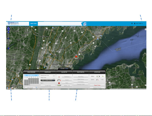
Navigation Arrows
Zoom Bar Dashboard Last Known Location
Change Map View

Tracking information is displayed using Google Maps, so navigation is
similar to what most people have grown used to from internet-based
mapping solutions. You can use the Navigation arrows and Zoom Bar to
move around the map, or drag the map using your mouse and zoom using
a click wheel mouse.
At the bottom of the pop-up window are the Zoom, Street View, and Live
Tracker buttons.
• Zoom will perform the same task as using the Zoom bar on the left side
of the map; zooming in on the icon you have selected.
• Street View will open up a separate window displaying Google’s Street
View, if available.
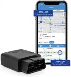
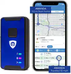
The White Target icon will appear where a tracker transmitted most
recently. Click on an icon to bring up a pop-up box. This will show your
tracker’s name, the distance it has traveled on this trip, what direction it
was moving in, speed, battery information, and start and stop locations.
Start will display the beginning location of the current trip and the time it
was recorded. Stop will display the most recent location from the device,
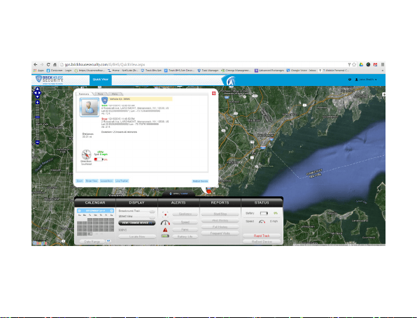

as well as the time it was reported. The More tab is not currently active.
Future updates to the platform will utilize this tab.
The Geofence tab allows you to create quick geofences, based on the
location you are currently viewing and route the device was following.
Use the Circular GeoFence radio button to create a perimeter around
the location you are clicked on. Use the Route GeoFence radio button to
create a boundary that will follow the entire trip your device was on.
Give the GeoFence a name in the GeoFence Name window, and add a
short description in the Description box (optional).
Use the Action dropdown box to choose if you would like an alert created
when the device enters the chosen area, exits the area, or both. Use the
Radius box to choose how large the area will be. You can enter values
below a mile as decimals. For example: A half-mile radius geofence would
be entered as .5.
When you’re done, press the Create Geofence button to save.
The Alerts will display the most recent Geofence, Speed, Panic, or Power
alerts that have been triggered
The Video Links tab is not currently active. Future updates will take
advantage of this tab.
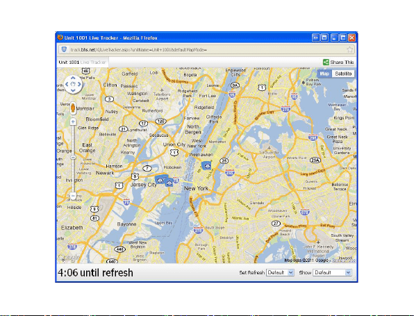
Live Tracker will open up a separate window displaying your devices’
locations, and allows you to see past locations. Using the drop-down
boxes on the bottom right of the window, you can adjust how often your
screen refreshes and how many locations will appear on the screen. The
counter on the bottom left of the window displays how long it will be until
your screen refreshes. You can email a link to this page, allowing other
users to view your tracker’s location by clicking on the Share This icon
in the upper right hand corner of the window. When doing so, you may
choose how long the link will be active before it expires using the Link
Expiration dropdown.
Using the Dashboard
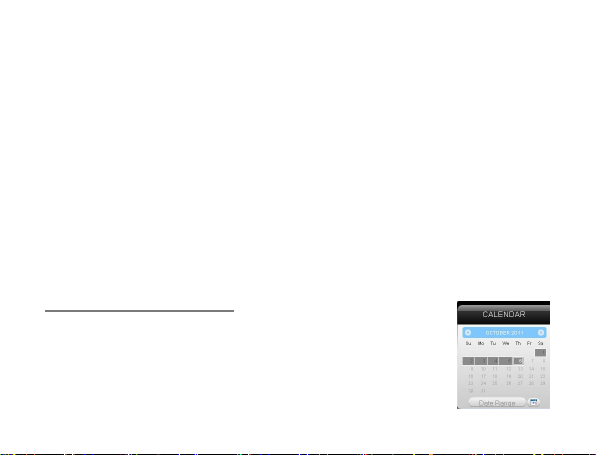
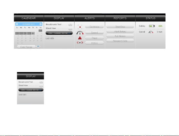
The Calendar allows a user to choose from which dates
information can display. Any date that has tracking
information will be highlighted. Simply click on that date to
display information. To choose multiple days, click on the
Date Range button, input a start and end date, and press
Search. Press the Current Date button to return to viewing the current day’s
information. When searching by date, all locates generated in the chosen
timeframe will display as breadcrumbs.
Under the Display section you can see a list of all devices
currently displaying information on the map. Click on
the View/Change Device button to choose which of your
devices will display on the map. This button only serves a
purpose if there are multiple devices on your account.
Breadcrumb Trail will display all locations, or
breadcrumbs, generated on the date you currently have
displayed, with all locations connected by a line. Click on any individual
breadcrumb location to see detailed information. The BrickHouse shield

icon represents the start and stop of a trip, green circles mean the device
was moving with the arrow indicating direction, and red octagons indicate
stops.
Click on the Street View button to open a Google Street View window from
the most recent location of the device. This function will only work if
Google Street View is available in that location.
The Alerts section lets you manage what kinds of alerts
your device will create and how you will be notied.
Click the Geofence button to manage your geofences. The
Geofence Alert
Conguration tab lets you choose when and where alerts
will be sent. Select the device you would like to edit by
checking the box next to it.
Highlight which days you would like to congure by clicking on each. You
may choose to enter certain hours during which alerts will be active, or
leave these elds blank to have them sent all the time.

To create a circular geofence around an area, click on Circle and then click
on the spot on the map you want to create your geofence around. Hold
down the left mouse button and drag the cursor until your geofence is the
size you want, and release the mouse button.
Choose if duplicate alerts will or will not be created if the device stays
inside or outside a geofence for a certain period of time using the slider
bar.
Choose what icon will appear where a geofence alert was created using
the Alert Image dropdown box.
Enter Email Address allows you to choose where alert notications will be
sent. Click on the + icon to add the phone numbers you want to be texted.
In the Create New Geofence tab you can create geofences around any
area in dierent shapes. Navigate to the area on the map where you would
like to create a geofence. Click on the Circle, Polygon, or Route button. It is
suggested that all geofences be in at least a .2 mile radius, or at least 1 city
block around an area to allow for GPS drift
To create a circular geofence around an area, click on Circle and then click

on the spot on the map that you want to create your geofence around.
Hold down the left mouse button and drag the cursor until your geofence is
the size you want, then release the mouse button.
The Polygon button allows you to create geofences in dierent shapes.
Each point you click on will be a corner of your perimeter.
A Route geofence will be straight lines. You must choose how far a device
will need to be away from the route before a report is generated.
Once you have created a geofence, assign it a name in the Geofence eld
and hit Save. You may also choose to enter a short description for your
geofence.
The Assign Geofence tab allows you to activate and deactivate geofences.
Select a device from the dropdown menu to see what geofences are
currently active. Click on an Assigned Geofence to view and edit its
conguration. Click the Remove link to deactivate a geofence. Hit Save
once you have nished making changes.
Click on the check box for any Available geofence to edit its conguration
and press the Save button to implement it

The View Geofence tab allows you to view your geofences.
Click the Speed button on the dashboard to set up speed alerts. Simply
select your device and enter a speed which, when exceeded, will generate
an alert. Choose the days and times you would like the alert to be active, if
you would like duplicate alerts to be ignored, and enter the email address
where you wish to receive your notifications. If you would prefer to receive
alert notifications via text message, click on the + button and enter your
phone information. Hit Save once you have finished configuring your alerts.
NOTE: The Livewire 4 does not take advantage of the BrickHouse Tracking
platform’s Panic alert function. Also, due to this device being a hardwired
tracker, it does not indicate a battery level. This option will only work for
battery-operated GPS trackers.

Y
ou can run 4 different types of reports, listed below. To run a report, click
on one of the buttons, choose the device you would like to run a report on
from the dropdown box, choose the dates you would like to run your
report from in the upper right corner, and press the magnifying glass
search icon. You can export any generated reports to Microsoft Excel by
clicking on the export button in the upper right corner of the window.
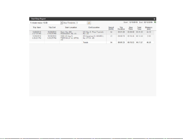
Start/Stop reports will list trips between stopping points, with starting and
ending locations, as well as speed information, trip duration, stop time, and
the distance traveled.
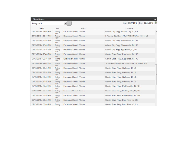
The Alert History button will show you all alerts generated during the
specied time and where they occurred.
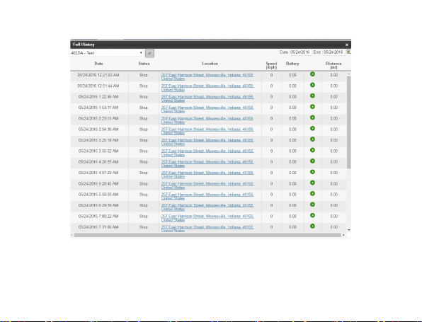
The Full History button includes individual location information such as:
location, time of transmission, battery life, speed, and distance from its
previous location.
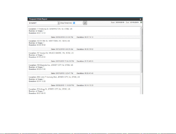
The Frequent Visits button will create a list of addresses that the device
has reported from and show how many times the device reported from that
spot.

Changing Your Password
To change your password, click on the account name, which should
appear in the upper right corner of the browser window. Once complete,
just click on Quick View to return to your tracking page.
Support
To access FAQs, as well as other support materials for your device visit
help.brickhousesecurity.com
Live support is available:
M - F: 9am- 8pm EST
Sat - Sun: 9am- 6pm EST
Phone:1-800-654-7966. or Email: support@brickhousesecurity.com