
SFJAR8
NUMBER 917.252700
OWNER'S MANUAL
=Assembly
• Operation
• Customer Responsibilities
• Service and Adjustments
®Repair Parts
®
Convertible
CAUTION: Read and follow all safety rules and instructions before operating this equipment.
FOR CONSUMER ASSISTANCE HOT LINE, CALL THIS TOLL FREE NUMBER: 1-800_659-5917
I IIIIIIIIIIIIIIIII..................................
SAFETY RULES
A Safe Operation Practices for Ride-On Mowers A
IMPORTANT: THIS CUTTING MACHINE IS CAPABLE OF AMPUTATING HANDS AND FEET AND THROWING OBJECTS°
FAILURE TO OBSERVE THE FOLLOWING SAFETY INSTRUCTIONS COULD RESULT IN SERIOUS INJURY OR DEATH°
L GENERAL OPERATION
• Read, understand, and follow all instruction'sin the manual
and on the machine before starting.
° Only allow responsible adults, who are familiar with the
instructions, to operate the machine.
° Clear the area of objects such as rocks, toys, wire, etc.,
which could be picked up and thrown by the blade_
° Besure the area isclear of otherpeople before mowing, Stop
machine if anyone enters the area.,
• Never carry passengers°
• Do not mow in reverse unless absolutely necessary° Always
look down and behind before and while backing.
° Be aware of the mower discharge direction and do not point
it at anyone. Do not operate the mower without either the
entire grass catcher or the guard in place.
', Stow down before turning°
• Never leave a running machine unattended° Always turn off
blades, set parking brake, stop engine, and remove keys
before dismounting.
• Turn off blades when not mowing.
• Stop engine before removing grass catcher or unclogging
chute.
= Mow only in daylight or good artificial light.
• Do not operate the machine while under the influence of
alcohol or drugs,
• Watch for traffic when operating near or crossing roadways.
° Use extra care when loading or unloading the machine into
a trailer or truck°
I!. SLOPE OPERATION
Slopes are a major factor related to loss-of-control and
tipover accidents, which can result in severe injury ordeath.
All slopes require extra caution, If you cannot back up the
slope or if you feel uneasy on it, do not mow ito
DO:
• Mow up and down slopes, not across_
° Remove obstacles such as rocks, tree limbs, etc.
• Watch for holes, ruts, or bumps. Uneven terrain could
overturn the machine.. Tall grass can hide obstacles.,
° Use slow speed.. Choose a low gear so that you will not have
to stop or shift while on the slope.
• Follow the manufacturer's recommendations for wheel
weights or counterweights to improve stability.
° Use extra care with grass catchers or other attachments.
These can change the stability of the machine°
° Keep all movement on the slopes slowand gradual Do not
make sudden changes in speed or direction°
• Avoid starting or stopping on a slope.. If tires lose traction,
disengage the blades and proceed slowly straight down the
slope..
DO NOT:
° Do not turnon slopes unlessnecessary, and then,turnslowly
and gradually downhill, if possible.
• Do not mow near drop-offs, ditches, or embankments,. The
mower coutd suddenly turn over if a wheel is over the edge
of a cliffor ditch, or if an edge caves in.
• Do not mow on wet grass,. Reduced traction could cause
sliding°
• Do not try to stabilize the machine by puttingyour foot on the
ground,
° Do not use grass catcher on steep slopes.
2
IIi. CHILDREN
Tragic accidents can occur if the operator is not alert to the
presence of .children° Children are often attracted to the
machine and the mowing activity° Never assume that
children will remain where you last saw them.,
• Keep children out of the mowing area and under the watchful
care of another responsible adult,.
° Be alert and turn machine off if children enter the area°
• Before and when backing, look behind and down for small
children.
• Never carry children.. They may fall off and be seriously
injured or interfere with safe machine operation.
° Never allow children to operate the machine.
• Use extra care when approaching blind comers, shrubs,
trees, or other objects that may obscure vision.
IV. SERVICE
• Use extra care inhandling gasoline and other fuels_ They are
flammable and vapors are explosive.
- Use only an approved container_
- Never remove gas cap or add fuel with the engine
running.. Allow engine to cool before refueling. Do not
smoke_
- Never refuel the machine indoors.
- Never store the machine or fuel container inside where
there is an open flame, such as a water heater..
. Never run a machine inside a closed area_
° Keep nuts and bolts, especially blade attachment bolts, tight
and keep equipment in good condition..
• Never tamper with safety devices. Check their proper
operation regularly,.
• Keep machine free of grass, leaves, or other debris build-upo
Clean oil or fuel spillage° Allow machine to cool before
storing,.
• Stop and inspect the equipment if you strike an object.
Repair, if necessary, before restarting.
• Never make adjustments or repairs with the engine running_
• Grass catcher components are subject to wear, damage, and
deterioration, which could expose moving parts or allow
objects to be thrown. Frequently check components and
replace with manufacturer's recommended parts, when nec-
essary..
• Mower blades are sharp and can cut. Wrap the blade(s) or
wear gloves, and use extra caution when servicing them..
° Check brake operation frequently. Adjust and service as
required..
A Look for this symbol to point out im-
portant safety precautions. It means
CAUTION!!! BECOME ALERT!!! YOUR
SAFETY IS INVOLVED,
CAUTION: Always disconnect spark plug
A wlreand placewire wherelt cannot contact
spark plug in order to prevent accidental
starting when setting up, transporting,
adjusting or making repairs.
A WARNING A .........
The engine exhaust from this product con-
tains chemicals known to the State of Califor-
nia to cause cancer, birth defects, or other
reproductive harm.

CONGRATULATIONS on your' purchase of a Sears
Tractor° It has been designed, engineered and manufac-
tured to give you the best possible dependability and
performance..
Should you experience any problem you cannot easily
remedy, please contact your nearest Sears Authorized
Service CentedDepartment+ We have competent, well-
trained technicians and the proper tools to service or repair
this tractor°
Please read and retain this manual. The instructions will
enable you to assemble and maintain your unit properly,,
Always observe the "SAFETY RULES".
_ODEL
_IUMBER 917°252700
3ER1AL
NUMBER
DATE OF PURCHASE
THE MODELAND SERIAL NUMBERS WILL BE FOUND
ON A PLATE UNDER THE SEAT.
YOU SHOULD RECORD BOTH SERfAL NUMBER AND
DATE OF PURCHASE AND KEEP IN A SAFE PLACE
FOR FUTURE REFERENCE
)RODUCT SPECIFICATIONS
-tORSEPOWER: 18.0
GASOLINE CAPACITY 3+5GALLONS
AND TYPE: UNLEADED REGULAR
OIL TYPE (API-SFISG): SAE 30 (above 32°F)
SAE 5W+30 (below 32°F)
OIL CAPACITY: Wi FILTER: 4.0 PINTS
W/O FILTER: 3.5 PINTS
SPARK PLUG: CHAMPION RV17YC
(GAP: ,,025")
VALVE CLEARANCE: INTAKE: °003" - +006"
EXHAUST: B13" - +016"
GROUND SPEED (MPH): FORWARD:
1st 1+1
2nd 1+5
3rd 23
4th 3.5
5th 4.5
6th 5.7
REVERSE: 1.8
TIRE PRESSURE: FRONT: 14 PSI
REAR: 10 PSI
CHARGING SYSTEM: 15 AMPS @ 3600 RPM
BLADE BOLT TORQUE: 30-35 FT..LBS
MAINTENANCE AGREEMENT
A Sears Maintenance Agreement is available on this prod-
uct,. Contact your nearest Sears store for details,,
CUSTOMER RESPONSIBILITIES
, Read and observe the safety rules.
• Follow a regular schedule in maintaining, caring for and
using your tractor.
° Follow the instructions under "Customer' Responsibili-
ties" and "Storage" sections of this owner's manual.,
WARNING: This tractor is equipped with an internal
combustion engine and should not be used on or near any
unimproved forest-covered, brush-covered or grass-coy+
ered tand unless the engine's exhaust system is equipped
with a spark arrester meeting applicable local or state laws
(if any)° If a spark arrester is used, it should be maintained
in effective working order' by the operator.
In the state of California the above is required by law
(Section 4442 of the California Public Resources Code).
Other states may have similar laws. Federal laws apply on
federal lands., A spark arrester for the muffler is available
through your nearest Sears Authorized Service Center/
Department (See REPAIR PARTS section ofthis rnanual),.
LIMITED TWO YEAR "WARRANTY ON CRAFTSMAN RIDING EQUIPMENT
For two (2) years from the date of purchase, if this Craftsman Riding Equipment is maintained, lubricated and tuned up according
to the instructionsin the owner's manual, Sears will repair or replace, free of charge, any parts found to be defective in material or
workmanship..
This Warranty does not cover:
. Expendable items which become worn duringnormal use, such as blades, spark plugs, air cleaners, belts, etc..
• Tire replacement or repair caused by puncturesfrom outside objects, such as nails, thorns, stumps, or glass.
° Repairs necessary because of operator abuse, negligence, improper storage or accident or the failure to maintain the
equipment according to the instructionscontained in the owner's manual
• Riding equipment used for commercial or rental purposes.,
LIMITED 90 DAY WARRANTY ON BATTERY
For' ninety (90) days from date of purchase, if any battery included with this riding equipment proves defective in material or
workmanship and our testing determines the battery will not hold a charge, Sears will replace the battery at no charge+
IN+HOME WARRANTY SERVICE ON YOUR CRAFTSMAN RIDING EQUIPMENT IS AVAILABLE AT NO-CHARGE FOR 30
DAYS FROM THE DATE OF PURCHASE PLEASE CONTACT YOUR NEAREST SERVICE CENTER. AFTER 30 DAYS FROM
THE DATE OF PURCHASE, WARRANTY SERVICE IS AVAILABLE BY TAKING YOUR CRAFTSMAN RIDING EQUIPMENT TO
YOUR NEAREST SEARS SERVICE CENTER. (IN-HOME WARRANTY SERVICE WILL STILL BE AVAILABLE AFTER 30 DAYS
FROM THE DATE OF PURCHASE BUT A STANDARD TRIP CHARGE WILL APPLY,) THIS WARRANTY APPLIES ONLY
WHILE THiS PRODUCT IS IN THE UNITED STATES,
This Warranty gives you specific legal rights, and you may also have ether rightswhich may vary from state to state,.
SEARS, ROEBUCK AND CO. D/817 WA, HOFFMAN ESTATES, IL 60179
3
i, i1,1,illlllHiH i HI
TABLE OF CONTENTS
SAFETY RULES ............................................................ 2
PRODUCT SPECIFICATIONS ...................................... 3
CUSTOMER RESPONSIBILITIES ..................... 3, 15=18
WARRANT'/ ........................ :......................... .;............... 3
TRACTOR ACCESSORIES .......................................... 5
ASSEMBLY ............................................................... 7-9
OPERATION .......................................................... 10-14
MAINTENANCE SCHEDULE ..................................... 15
SERVICE AND ADJUSTMENTS ........................... 19_23
STORAGE ................................................................... 24
TROUBLESHOOTING ........................................... 25_26
REPAIR PARTS _ TRACTOR ................................ 28_45
REPAIR PARTS - ENGINE .................................... 46m51
PARTS ORDERING/SERVICE ............... BACK COVER
INDEX
A
Accessories.................................................................5
Adjustments;
Brake .........................................................21
Carburetor .............................................23
Mower
Front-To-Back ......................................20
Side-To-Side ..............................20
Throttle Control Cable ................... 23
Air Filter, Engine .........................................17
Air Screen, Engine ...........................................18
Assembly ....................................................7-9
B
Battery:
Charging ..................................................8
Cleaning ........................................................16
Starting with Weak Battery ............22
Storage ...................................................24
Terminals ..........................................16
Belt:
Motion Drive
Removal/Replacement ................2t
Mower Belt(s)
Removal/Replacement ........... 21
Blade:
Sharpening .............................................16
Replacement ...........................................16
Brake Adjustment .....................................21
C
Carburetor Adjustment ......................................23
Controls, Tractor ............................................11
Customer Responsibilities ...............15-18
Engine:
Air Fitter ...............................................17
Air Screen ..........................................18
Cooling Fins ......................................18
Engine Oil .....................................13,17
Fuel Filter ..............................................18
Spark Plug(s) ...............................18
Tractor:.
Battery .................................................16
Blade ................................................16
Lubrication Chart ...................................15
Maintenance Schedule ............ 15
Tire Care .....................................8,16,22
Transaxle ..............................................17
Cutting Height, Mower .............................12
E
Electrical:
Interlocks and Relays ....................22
Schematic ....................................................27
Wiring Diagram .......................................28
Engine:
Air Filter .................................................17
Air Screen ................................................18
Cooling Fins ...............................................18
Oil Change .........................................17
Oil Level ...................................................13
Oil Type ..........................................t3,17
Preparation ..................................... 13
Repair Parts ...............................46-51
Starting..................................................14
Storage .................................................24
F
Filter.
Air Filter ...............................................17
Fuel .................................................................18
Fuel:
Type ............................................................t3
Storage .......................................................24
Fuse .............................................................................22
H
Hood Removalflnstallation ..........................22
L
Leveling Mower Deck ..............................20
Lubrication:
Chart ..................................................................15
Engine ...............................................17
M
Maintenance Schedule ....................... t5
Mower.
Adjustment, Front-to-Back ..................20
Adjustment, Side-to-Side .....................20
Blade Replacement ...................................16
Blade Sharpening ......................... 16
Cutting Height ............................... 12
Installation ................................................19
Operation ...................................................13
Removal .............................................19
Mowing Tips ..........................................................14
Muffler ...........................................................18
Spark Arrester ........................... 3,36
O
Oi!:
Cold Weather Conditions ............13,17
Engine ...................................................................17
Storage ........................................... 24
Operation .......................................... 10-14
Operating Mower ....................................................13
Options:
Accessories ....................................... 5
Spark Arrester ............................. 3,36
P
Parking Brake ................................... 11-12
Parts Bag ............................................................6
Pads, Replacement/Repair ..............28-45
Product Specifications.................................3
R
Repair Parts ...........................................................28-45
S
Safely Rules ...........................................................2
Seat ..................................................................................8
Service and Adjustments ........................19-23
Carburetor ..................................................23
Fuse ...................................................................22
Hood Remova!/Installation .................22
Motion Drive Belt
Removal/Replacement ....................21
Mower Belt(s)
Removal/Replacement .............21
Mower Adjustment
Front-to-Back ..............................20
Side-to-Side .................................20
Mower Removal/Installation .......... 19
Tire Care ..................................8,!6,22
Slope Guide Sheet ............................... 55
Spark Plug(s) ........................................ 18
Specifications.....................................................3
Starling the Engine .............................13-14
Steering Wheel .......................................7,22
Stopping the Tractor ...............................12
Storage .................................................................24
T
Throttle Control Cable Adjustment ...... 23
Tires ................................................................8,16,22
Troubleshooting Chart .................................25-26
Transaxle ................................................................17
W
" Warranty .........................................................................3
Wiring Diagram ...................................... 28
Wiring Schematic .......................................................27
4
i i1,,1,,,1,1, ,11,1, ii , i i,,Jl,JlJ
ACC RIES AND ATTACHM
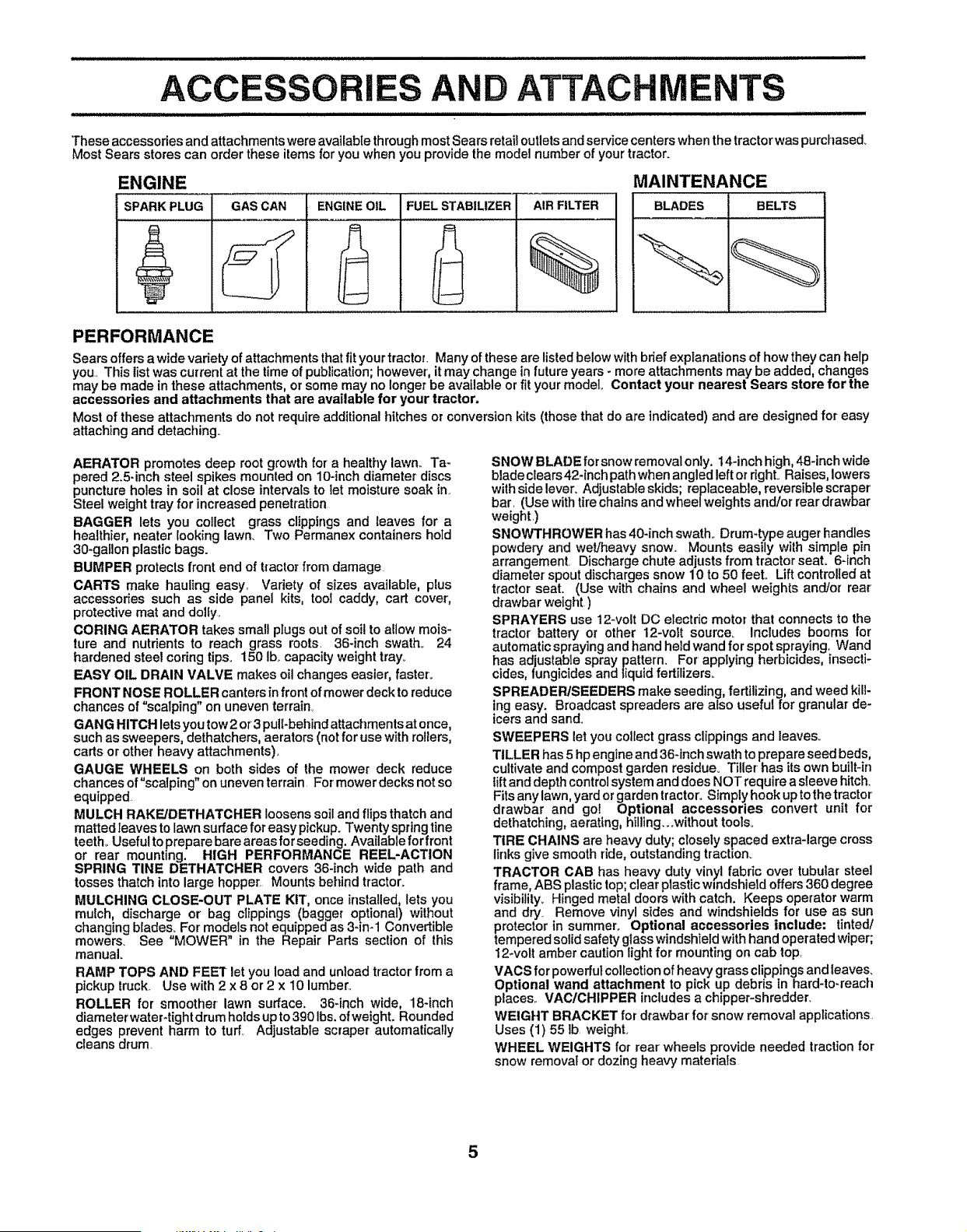
These accessories and attachments were available throughmost Sears retail cutletsand service centers when the tractor was purchased+
Most Sears stores can order these items for you when you provide the model number of your tractor+
ENGINE MAINTENANCE
SPARK PLUG BLADES BELTSGAS CAN ENGINEOIL FUEL STABILIZER AIR FILTER
%
PERFORMANCE
Sears offers a wide variety of attachments that fit your tractor. Many of these are listedbelow with brief explanations of how they can help
you,, This list was current at the time of publication;however, it may change in future years - more attachments may be added, changes
may be made in these attachments, or some may no longer be available or fit your model Contact your nearest Sears store for the
accessories and attachments that are available for your tractor.
Most of these attachments do not require additional hitches or conversion kits (those that do are indicated) and are designed for easy
attaching and detaching+
AERATOR promotes deep root growth for a healthy lawn.. Ta-
pered 2.5-inch steel spikes mounted on 10-inch diameter discs
puncture holes in soil at close intervals to let moisture soak in.
Steel weight tray for increased penetration
BAGGER lets you collect grass clippings and leaves for a
healthier, nearer looking lawn. Two Permanex containers hold
30-gallon plastic bags.
BUMPER protects front end of tractor from damage
CARTS make hauling easy. Variety of sizes available, plus
accessories such as side panel kits, tool caddy, cart cover,
protective mat and dolIy.
CORING AERATOR takes small plugs out of soil to allow mois-
ture and nutrients to reach grass roots. 36-inch swath. 24
hardened steel coring tips+ 150 Ib+capacity weight tray+
EASY OIL DRAIN VALVE makes oil changes easier, faster.
FRONT NOSE ROLLER canters [nfront of mower deck to reduce
chances of "scalping" on uneven terrain+.
GANG HITCH lets you tow 2 or3 puiI+behin d attachments at once,
such as sweepers, dethatchers, aerators (not for use with rollers,
carts or other heavy attachments)+
GAUGE WHEELS on both sides of the mower deck reduce
chances of "scalping" on uneven terrain For mower decks not so
equipped
MULCH RAKE/DETHATOHER loosens soil and flips thatch and
matted leaves to lawn surface for easy pickup. Twenty spring line
teeth_ Useful toprepare bare areas for seeding. Available for front
or rear mounting. HIGH PERFORMANCE REEL-ACTION
SPRING TINE DETHATCHER covers 36-inch wide path and
tosses thatch into large hopper. Mounts behind tractor+
MULCHING CLOSE-OUT PLATE KIT, once installed, lets you
mulch, discharge or bag clippings (bagger optional) without
changing bIades_ For models not equipped as 3-in+1 Convertible
mowers+ See "MOWER" in the Repair Parts section of this
manual+
RAMP TOPS AND FEET let you load and unload tractor from a
pickup truck.. Use with 2 x 8 or 2 x 10 lumber..
ROLLER for smoother lawn surface. 36-inch wide, 18-inch
diameter water-tight drum holds up to 390 Ibs, of weight. Rounded
edges prevent harm to turf.. Adjustable scraper automatically
cleans drum.
SNOW BLADE for snow removal only. 14+inch high, 48-inch wide
blade clears 42-inch path when angled left or right+ Raises, lowers
with side lever+ Adjustable skids; replaceable, reversible scraper'
bar. (Use with tire chains and wheel we(ghts and/or rear drawbar
weight.)
SNOWTHROWER has 40-inch swath+ Drum+type auger handles
powdery and wet/heavy snow. Mounts easily with simple pin
arrangement. Discharge chute adjusts from tractor seat. 6-inch
diameter spout discharges snow 10 to 50 feet+ Lift controlled at
tractor seat. (Use with chains and wheel weights and/or rear
drawbar weight)
SPRAYERS use 12-volt DC electric motor that connects to the
tractor' battery or other 12-volt source_ Includes booms for
automatic spraying and hand held wand for spot spraying, Wand
has adjustable spray pattern+ For applying herbicides, insecti-
cides, fungicides and liquid fertilizers+
SPREADEPJSEEBERS make seeding, fertilizing, and weed kill-
ing easy+ Broadcast spreaders are also useful for granular de-
icers and sand.
SWEEPERS let you collect grass clippings and leaves+
TILLER has 5 hp engine and 36+inch swath to prepare seed beds,
cultivate and compost garden residue+ Tiller has its own built-in
lift and depth control system and does NOT require a sleeve hitch.
Fits any lawn, yard or garden tractor. Simply hook up tothe tractor
drawbar and go! Optional accessories convert unit for
dethatching, aerating, hilling...without tools+
TIRE CHAINS are heavy duty; closely spaced extra-large cross
links give smooth ride, outstanding traction+
TRACTOR CAB has heavy duty vinyl fabdc over tubular steel
frame, ABS plastic top; clear plasticwindshield offers 360 degree
visibility+ Hinged metal doors with catch. Keeps operator warm
and dry Remove vinyl sides and windshields for use as sun
protector in summer+ Optional accessories include; tinted/
tempered solid safety glass windshield with hand operated wiper;
12-volt amber caution light for mounting on cab top_
VACS for powerful co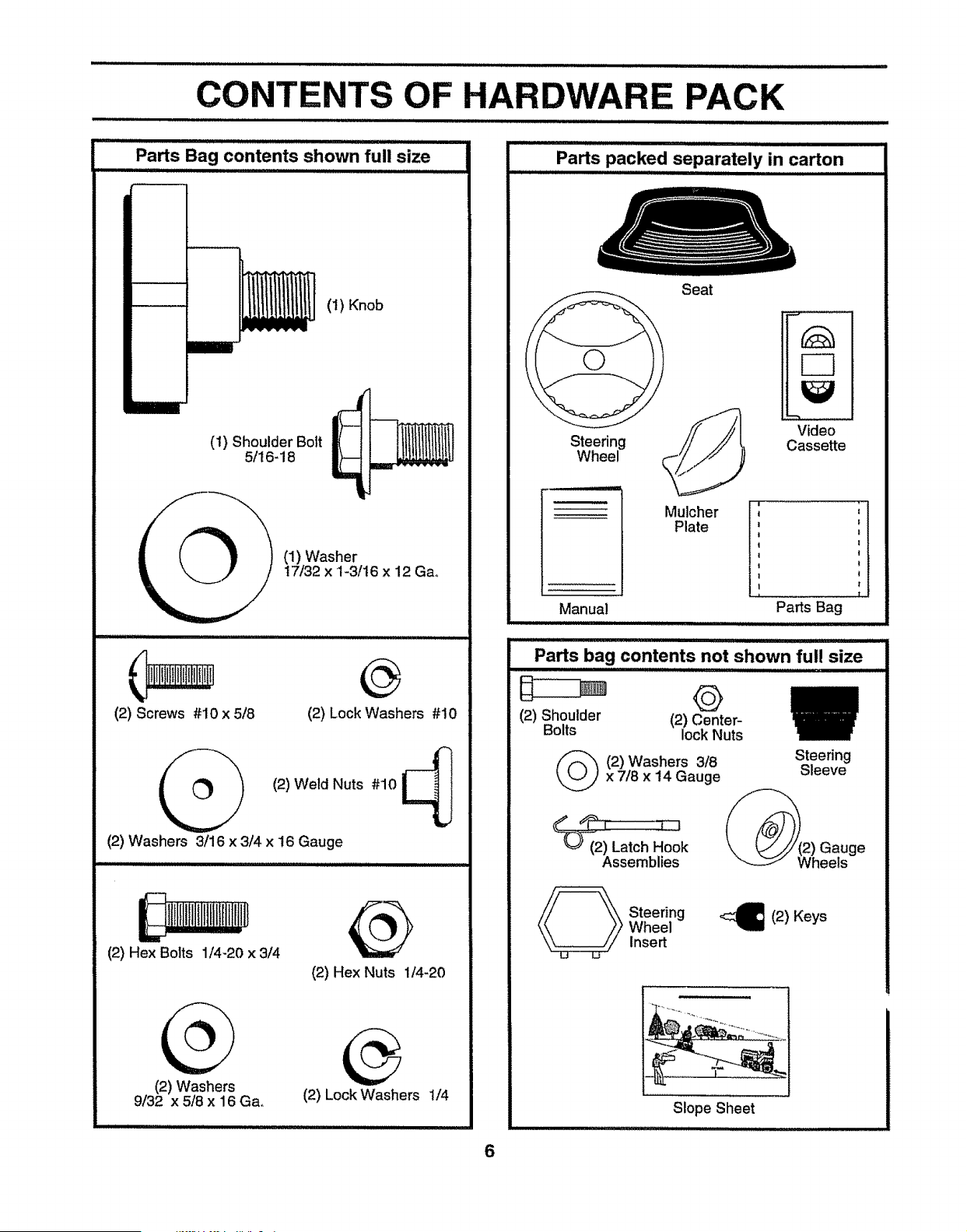
CONTENTS OF HARDWARE PACK
: : IIII IU [LIII' 'III'IIIIIIIU IIIII I I I
Parts Bag contents shown full size
(1) Knob
(1) Shoulder Bolt
5/16-18
(1) Washer
17/32 x 1-3/16 x 12 Ga°
(2) Screws #10 x 5/8 (2) Lock Washers #10
(2) Weld Nuts #10 _i
(2) Washers 3/16 x 3/4 x !6 Gauge
(2) Hex Bolts 1/4-20 x 3/4
(2) Washers
9/32 x 5/8 x 16 Gao
(2) Hex Nuts 1/4-20
(2) Lock Washers 1/4
Parts packed separately in carton
Steering
Wheel
Manual
Seat
Mulcher
Plate
Video
Cassette
I' ii
! f
Parts Bag
Parts bag contents not shown full size
I'1'111IIIII1'11'11 I ]]]
(2) Shoulder (2) Center-
Bolts lock Nuts
2) Washers 3/8x 7/8 x 14 Gauge
Steering
Sleeve
Gauge
_ teering
Wheel
Insert
(2) Keys
}
Slope Sheet
1111111111 i, I I
6
ii iii 111111111111111111111 ii , i_,,i,ii1,1,1111111111,1, ..................
Your new tractor has been assembled at the factory with exception of those parts left unassembled for shipping purposes+
To ensure safe and proper operation of your tractor all parts and hardware you assemble must be tightened securely° Use
the correct tools as necessary to insure proper tightness..
TOOLS REQUIRED FOR ASSEMBLY
A socket wrench set will make assembly easier+ Standard
wrench sizes are listed.
(2) 7/16" wrenches
(1) 1/2" wrench
(1) 9/16" wrench
Utility knife
When right or feft hand is mentioned in this manual, it
means when you are in the operating position (seated
behind the steering wheel)_
3/4" Socket w/drive ratchet
Tire pressure gauge
Phillips Screwdriver
TO REMOVE TRACTOR FROM CARTON
UNPACK CARTON
° Remove all accessible loose parts and parts cartons
from carton (See page 6).
• Cut, from top to bottom, along lines on all four corners
of carton, and lay panels flato
° Check for any additional loose parts or+cartons and
remove..
BEFORE ROLLING TRACTOR OFF SKID
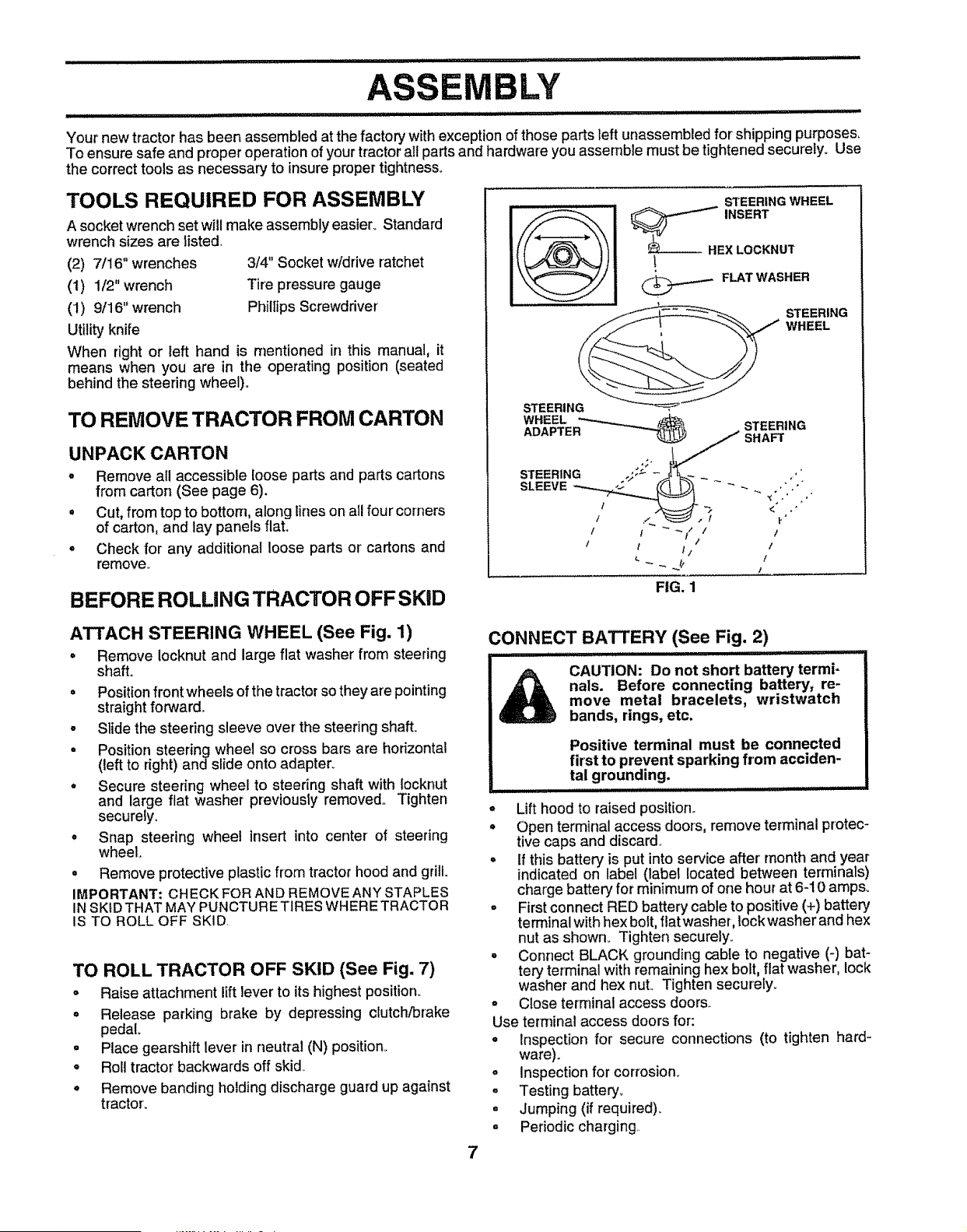
STEERING WHEEL
....- FLAT WASHER
STEERING
WHEEL
ATTACH STEERING WHEEL (See Fig. 1)
+ Remove Iocknut and large flat washer from steering
shaft+
• Position front wheels of the tractor so they are pointing
straight forward°
- Slide the steering sleeve over the steering shaft.
o Position steering wheel so cross bars are horizontal
(left to right) and slide onto adapter+
• Secure steering wheel to steering shaft with Iocknut
and large flat washer previously removed,, Tighten
securely+
. Snap steering wheel insert into center of steering
wheel.
° Remove protective plastic from tractor hood and grill.
IMPORTANT; CHECK FOR AND REMOVE ANY STAPLES
INSKtD THAT MAY PUNCTURETtRES WHERE TRACTOR
IS TO ROLL OFF SKID.
TO ROLL TRACTOR OFF SKID (See Fig. 7)
o Raise attachment lift lever to its highest position+
° Release parking brake by depressing clutch/brake
pedal
° Place gearshift lever in neutral (N) position.,
° Roll tractor backwards off skid.,
° Remove banding holding discharge guard up against
tractor+
CONNECT BATTERY (See Fig. 2)
....... ....... Hi :+
CAUTION: Do not short battery termi-
nals. Before connecting battery, re-
move metal bracelets, wristwatch
bands, rings, etc.
Positive terminal must be connected
first to prevent sparking from acciden-
tal grounding.
° Lift hood to raised position..
• Open terminal access doors, remove terminal protec-
tive caps and discard.,
• If this battery is put into service after' month and year
indicated on label (label located between terminals)
charge battery for minimum of one hour at 6-10 amps°
° First connect RED battery cable to positive (+) battery
terminal with hex bolt, flat washer, lock washer and hex
nut as shown° Tighten securely.,
o Connect BLACK grounding cable to negative (-) bat-
tery terminal with remaining hex bolt, flat washer, lock
washer and hex nuL Tighten securely+
° Close terminal access doors,.
Use terminal access doors for:
• Inspection for secure connections (to tighten hard-
ware).
= Inspection for corrosion+
° Testing battery+
= Jumping (if required)+
° Periodic charging.
7
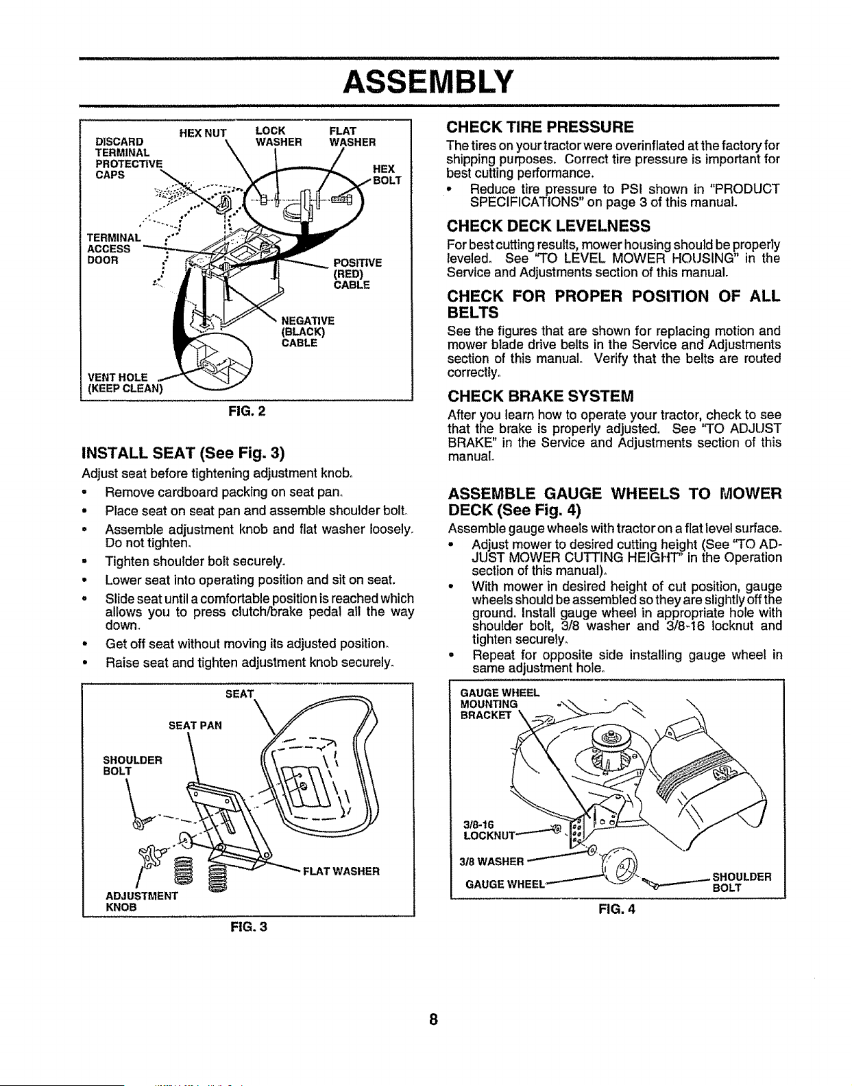
DISCARD
TERMINAL
PROTECTIVE
CAPS
HEX NUT
TERMINAL ,_"°
ACCESS
DOOR
LOCK FLAT
WASHER WASHER
HEX
NEGATIVE
(BLACK)
CABLE
VENT HOLE
i (KEEP CLEAN)
FIG. 2
POSITIVE
(RED)
CABLE
INSTALL SEAT (See Fig. 3)
Adjust seat before tightening adjustment knob°
• Remove cardboard packing on seat pan..
• Place seat on seat pan and assemble shoulder bolto
• Assemble adjustment knob and flat washer ioosely.
Do not tighten.
• Tighten shoulder bolt securety_
• Lower seat into operating position and sit on seat.
° Slide seat until a comfortable position is reached which
allows you to press clutch/Drake pedal all the way
down._
• Get off seat without moving its adjusted position.
• Raise seat and tighten adjustment knob securely.
LY
CHECK TIRE PRESSURE
The tires on your tractor were overinflated at the factory for
shipping purposes. Correct tire pressure is importantfor
best cutting performance.
° Reduce tirepressure to PSI shown in "PRODUCT
SPECIFICATIONS" on page 3 of this manual.
CHECK DECK LEVELNESS
For best cutting results,mower housing should be properly
leveled. See '`TO LEVEL MOWER HOUSING" in the
Service and Adjustments section of this manual.
CHECK FOR PROPER POSITION OF ALL
See the figures that are shown for replacing motion and
mower blade drive belts in the Service and Adjustments
section of this manual Verify that the belts are routed
correctlyo
CHECK BRAKE SYSTEM
After you learn how to operate your tractor, check to see
that the brake is properly adjusted. See "TO ADJUST
BRAKE" in the Service and Adjustments section of this
manual.
ASSEMBLE GAUGE WHEELS TO MOWER
DECK (See Fig. 4)
Assemble gauge wheels withtractor on a fiat level surfacer
° Adjust mower to desired cutting height (See 'q'O AD-
JUST MOWER CUTTING HEIGHT" in the Operation
section of this manual)°
° With mower in desired height of cut position, gauge
wheets should be assembled so they are slightly off the
ground.. Install gauge wheel in appropriate hole with
shoulder bolt, 3/8 washer and 3/8-t6 Iocknut and
tighten securely_
° Repeat for opposite side installing gauge wheel in
same adjustment hole..
SHOULDER
BOLT
ADJUSTMENT
KNOB
SEAT
SEAT PAN \_
FLAT WASHER
GAUGE WHEEL
MOUNTING
BRACKET
3/8-16
LOCKN UT_"-- _
318 WASHER
GAUGE WHEEL _
FIG. 4
BOLT
FIG. 3
8
MBLY
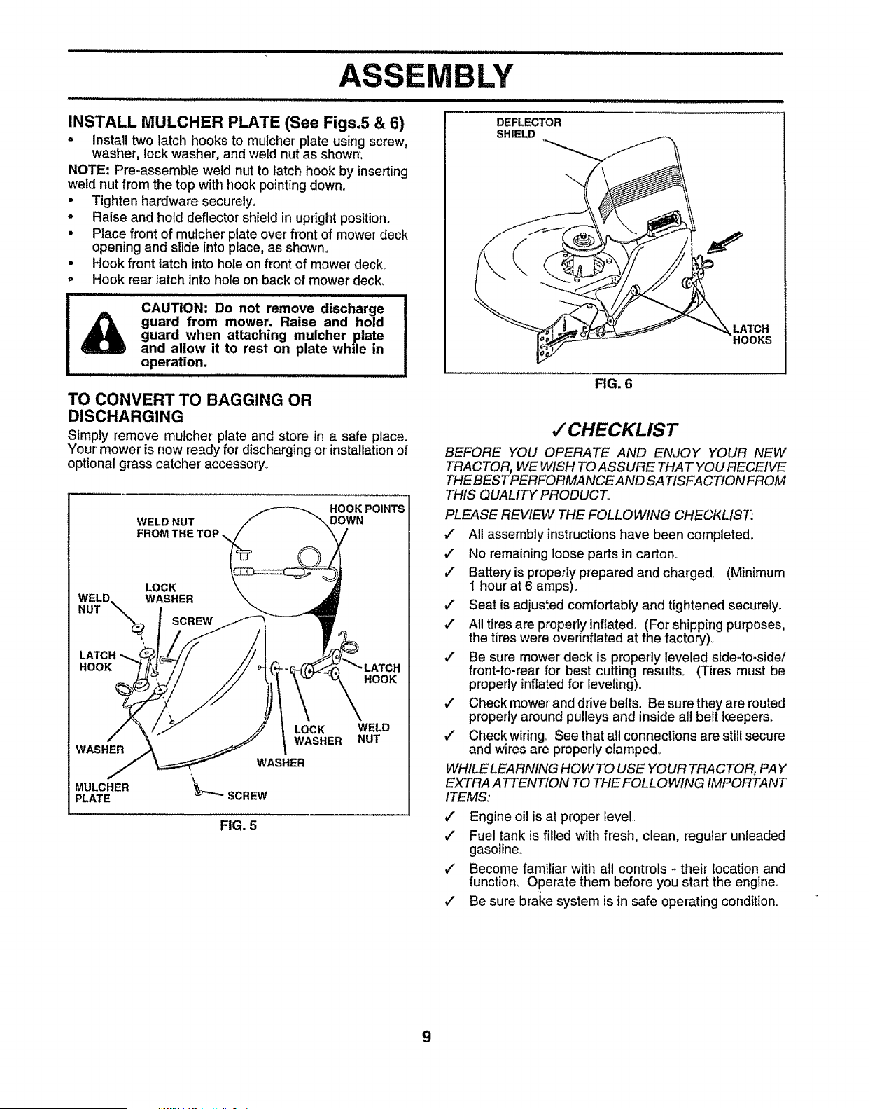
INSTALL MULCHER PLATE (See Figs.5 & 6)
° Install two latch hooks to muicher plate using screw,
washer, lock washer, and weld nut as shown:
NOTE: Pre-assemble weld nut to latch hook by inserting
wetd nut from the top with hook pointing down.
° Tighten hardware securely.
° Raise and hold deflector shield in updght position.
o Place front of mulcher plate over front of mower deck
opening and slide into place, as shown.
o Hook front latch into hole on front of mower deck°
° Hook rear latch into hole on back of mower deck_
I_ CAUTION: Do not remove discharge
guard from mower. Raise and hold
guard when attaching mulcher plate
and allow it to rest on plate while in
operation.
...................... ii III III II
TO CONVERT TO BAGGING OR
DISCHARGING
Simply remove muicher plate and store in a safe place.
Your mower is now ready for' discharging or installation of
optional grass catcher accessory°
WELD NUT
FROM THE
HOOK POINTS
DOWN
LOCK
WELD. WASHER
NUT _
LATCH
HOOK
HOOK
WASHER
MULCHER
PLATE
LOCK
WASHER
WELD
NUT
FIG. 5
DEFLECTOR
SHIELD
LATCH
'HOOKS
FIG. 6
,/CHECKLIST
BEFORE YOU OPERATE AND ENJOY '(OUR flEW
TRACTOR, WE WISH TOASSURE THAT YOU RECEIVE
THE BESTPERFORMANCEAND SATISFACTION FROM
THIS QUALITY PRODUCT.
PLEASE REVIEW THE FOLLOWING CHECKLIST:
J All assembly instructions have been completed.,
." No remaining loose parts in carton.
v" Battery is properly prepared and charged.. (Minimum
1 hour at 6 amps).
1/ Seat is adjusted comfortably and tightened securely.
,/ All tires are properly inflated. (For shipping purposes,
the tires were overinflated at the factory)..
,/ Be sure mower deck is propedy leveled side-to-side!
front-to-rear for best cutting results.. (Tires must be
properly inflatedfor leveling)°
v" Check mower'and drive belts. Be sure they are routed
properly around pulleys and inside all belt keepers°
,/ Check wiring° See that all connections are still secure
and wires are properly clamped_
WHILE LEARNING HOWTO USE YOUR TRACTOR, PAY
EXTRA ATTENTION TO THE FOLLOWING IMPORTANT
ITEMS:
,/ Engine oil is at proper level..
,/ Fue! tank is filled with fresh, clean, regular unleaded
gasoline..
,/ Become familiar with all controls - their location and
function_ Operate them before you start the engine..
,/ Be sure brake system is in safe operating condition°
9
n inl .................................................................
OPERATION
......... _: nlllullulllllll i n nnlllln I i I illllllll,lllll_,l_liii I
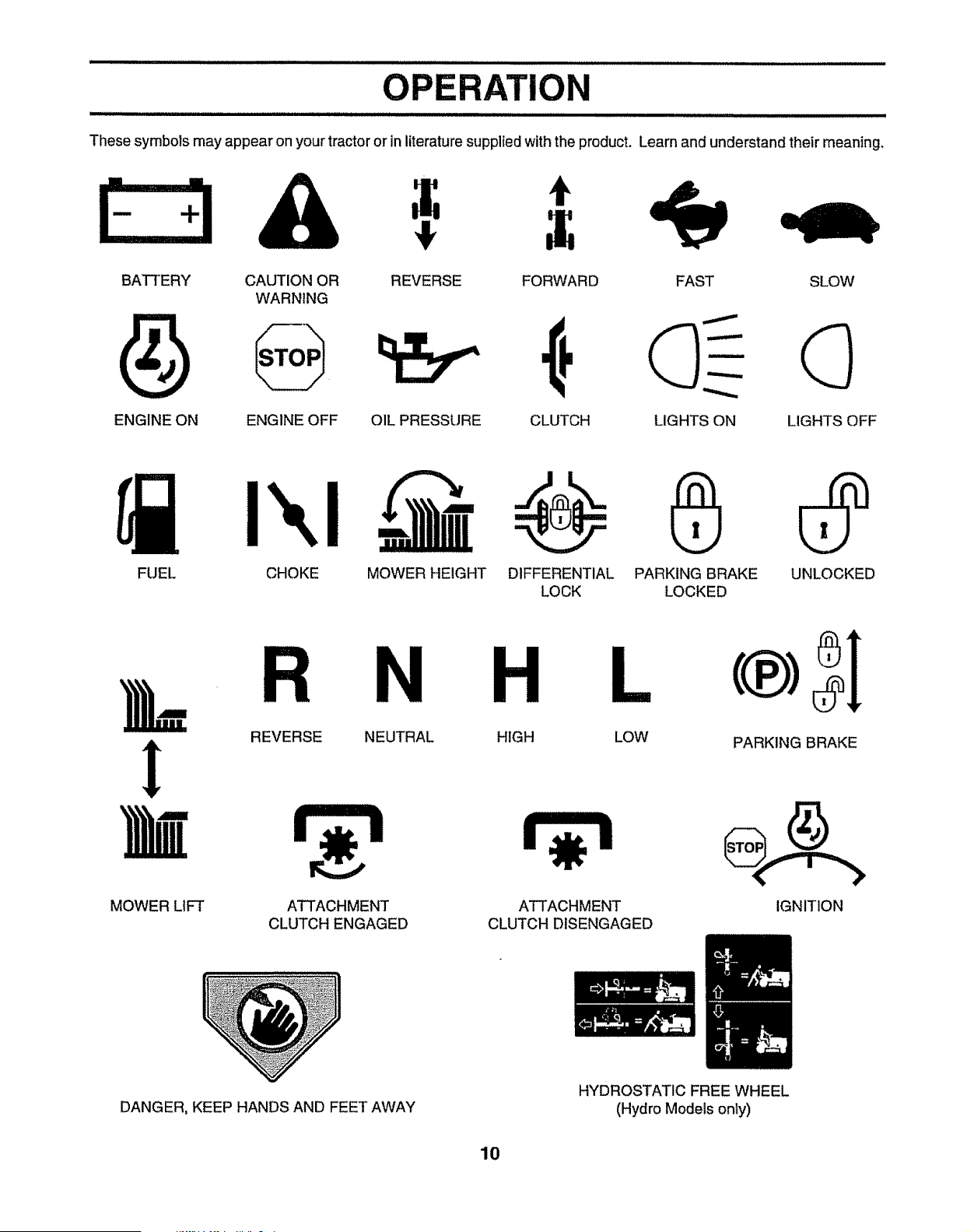
These symbols may appear on your tractor or in literature supplied with the product. Learn and understand their meaning,
t
BATTERY CAUTION OR REVERSE
WARNING
ENGINE ON ENGINE OFF OIL PRESSURE
FORWARD FAST SLOW
CLUTCH LIGHTS ON LIGHTS OFF
IIIIII!IIL¸
FUEL CHOKE MOWER HEIGHT
DIFFERENTIAL PARKING BRAKE UNLOCKED
LOCK LOCKED
!
MOWER LIFT
R N H
REVERSE NEUTRAL
ATTACHMENT
CLUTCH ENGAGED
HIGH LOW
ATTACHMENT
CLUTCH DISENGAGED
PARKING BRAKE
IGNITION
DANGER, KEEP HANDS AND FEET AWAY
HYDROSTATIC FREE WHEEL
(Hydro Models only)
10
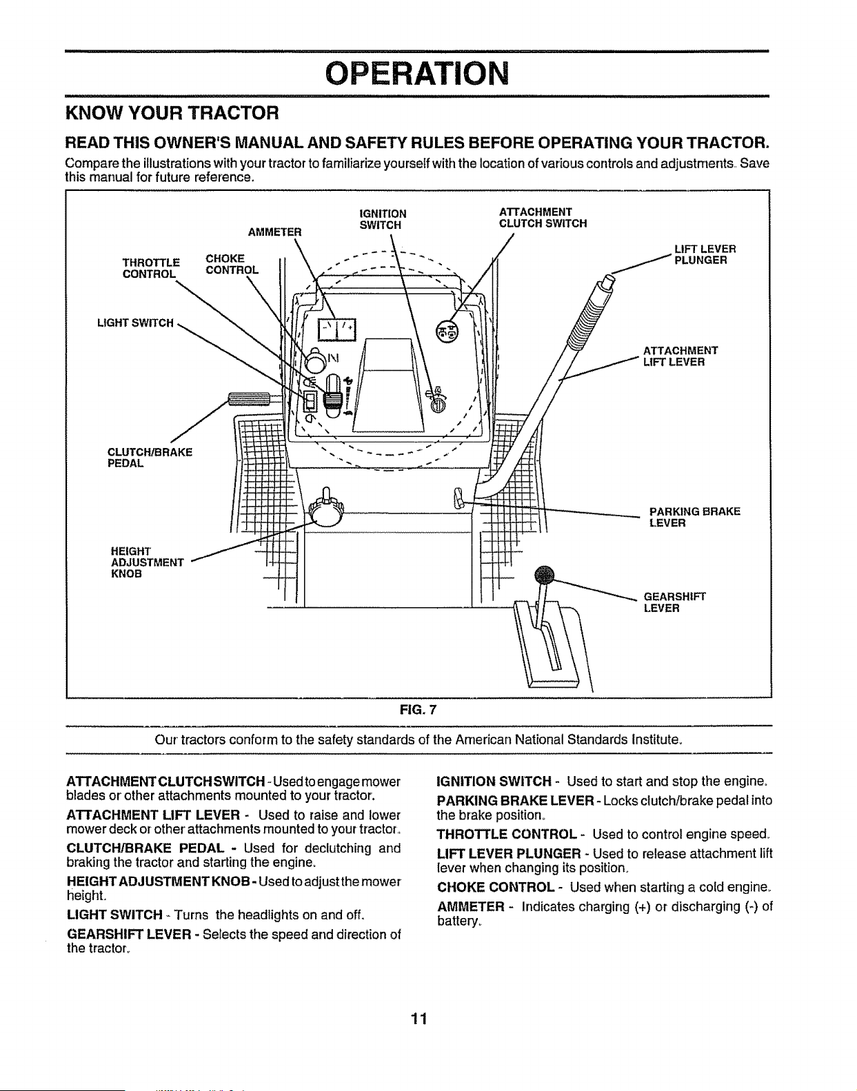
KNOW YOUR TRACTOR
READ THIS OWNER'S MANUAL AND SAFETY RULES BEFORE OPERATING YOUR TRACTOR.
Compare the illustrationswithyourtractorto familiarize yourselfwiththe locationof variouscontrolsand adjustments,, Save
this manual for future reference.
THROTTLE
CONTROL
CLUTCH/BRAKE
PEDAL
IGNITION ATTACHMENT
SWITCH CLUTCH SWITCH
AMMETER
_ - LIFT LEVER
CHOKE " - _ _ _ . PLUNGER
CONTROL
ATTACHMENT
LIFT LEVER
HEIGHT
ADJUSTMENT
KNOB
PARKING BRAKE
LEVER
GEARSHIFT
LEVER
FIG. 7
Our' tractors conform to the safety standards of the American National Standards Institute.
ATTACHMENT CLUTCH SWITCH _Used toengage mower
blades or' other attachments mounted to your tractor.
ATTACHMENT LIFT LEVER - Used to raise and lower
mower deck or other'attachments mounted to yourtractor,,
CLUTCH/BRAKE PEDAL - Used for declutching and
braking the tractor and starting the engine,
HEIGHT ADJUSTMENT KNOB- Used toadjustthe mower
height.
LIGHT SWITCH - Turns the headlights on and off,
GEARSHIFT LEVER - Selects the speed and direction of
the tractor..
IGNITION SWITCH - Used to start and stop the engine,
PARKING BRAKE LEVER - Locksclutch/brake pedal into
the brake position°
THROTTLE CONTROL - Used to control engine speed_
LIFT LEVER PLUNGER - Used to release attachment lift
lever when changing its position,
CHOKE CONTROL - Used when starting a cold engine_
AMMETER - Indicates charging (+) or discharging (-) of
battery.
11
iiii
OPERATION
i
The operation of any tractor can result in foreign objects thrown into the eyes, which can
result in severe eye damage. Always wear safety glasses or eye shields while operating
your tractor or performing any adjustments or repairs. We recommend a wide vision safety
mask over the spectacles or standard safety glasses.
i i i i i ii i iiiiiiiiiiii
HOW TO USE YOUR TRACTOR
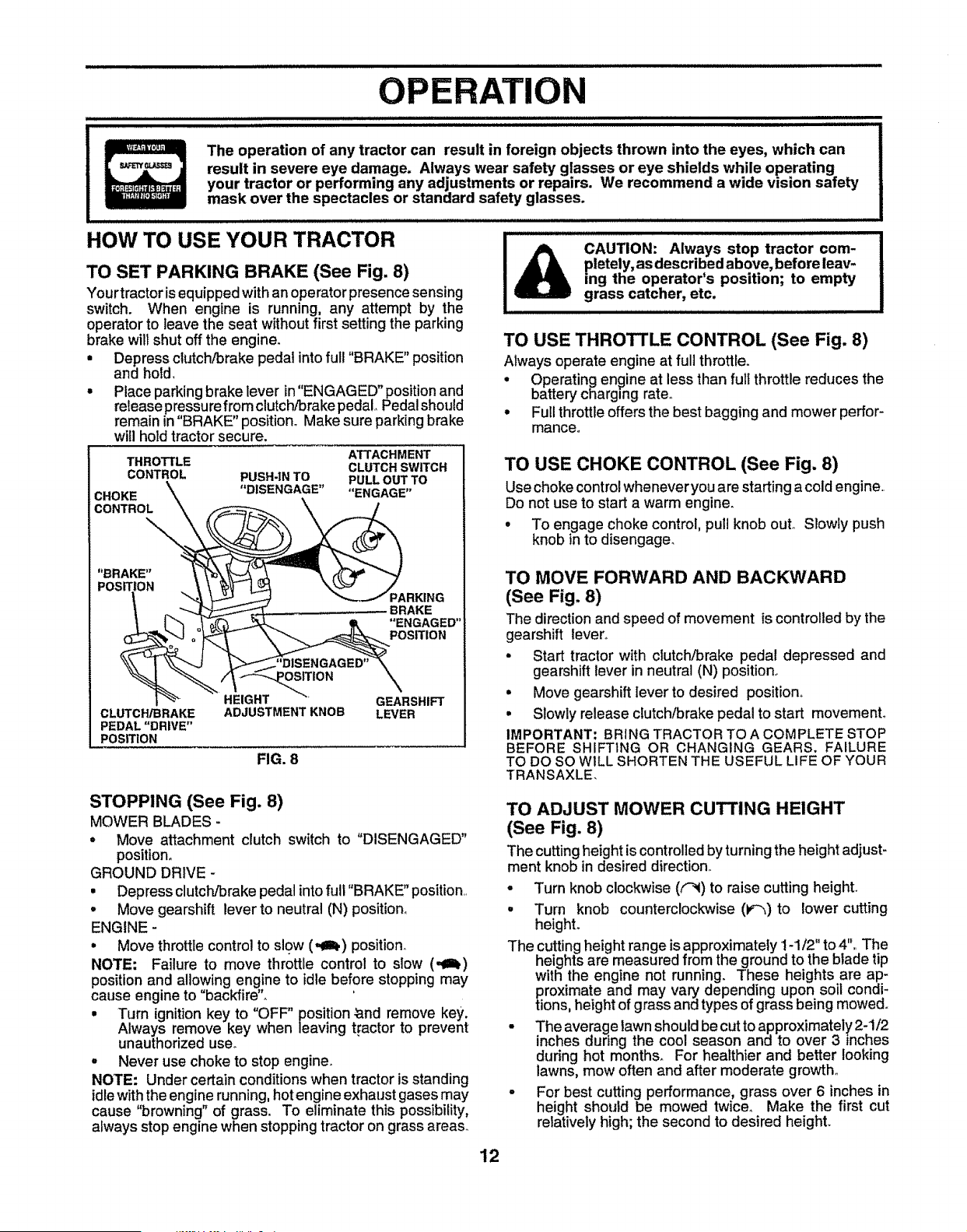
TO SET PARKING BRAKE (See Fig. 8)
Your tractor is equipped with an operator presence sensing
switch. When engine is running, any attempt by the
operator to leave the seat without first setting the parking
brake will shut off the engine.
= Depress clutch/brake pedal into full "BRAKE" position
and hold,
° Place parking brake lever in"ENGAGED" position and
release pressure from clutch/brake pedal, Pedalshould
remain in "BRAKE" position. Make sure parking brake
will hold tractor secure.
ATTACHMENT
THROTTLE CLUTCH SWITCH
CONTROL PUSH-IN TO PULL OUT TO
"DISENGAGE" "ENGAGE"
CHOKE _ __A
:CONTROL
"BRAKE"
POSITION
_A ED_,, :O RKING
;RAKE
B
_-"_, _ _ .... _ "ENGAGED
StTION
HEIGHT GEARSHIFT
CLUTCH/BRAKE ADJUSTMENT KNOB LEVER
PEDAL "DRIVE"
POSITION
FIG. 8
STOPPING (See Fig. 8)
MOWER BLADES -
* Move attachment clutch switch to "DISENGAGED"
position°
GROUND DRIVE -
. Depress clutcl_Jbrakepedal intofull "BRAKE" position.
° Move gearshift lever to neutral (N) position°
ENGINE -
. Move throttle control to slow (,_1_) position.
NOTE: Failure to move throttle control to slow (-€1_)
positionand allowing engine to idle before stopping may
cause engine to "backfire",,
. Turn ignition key to "OFF" position_and remove key,
Always remove key when leaving tractor to prevent
unauthorized use..
- Never use choke to stop engine.
NOTE: Under certain conditionswhen tractor is standing
idle withthe engine running,hotengine exhaust gases may
cause "browning" of grass. To eliminate this possibility,
always stop engine when stopping tractor on grass areas_
CAUTION: Always stop tractor com-
pletely, as described above, before leav-
ing the operator's position; to empty
grass catcher, etc.
I I IIII III IIIII I III III I II II II IIIIII I I II III I II III II II II
TO USE THROTTLE CONTROL (See Fig. 8)
Always operate engine at full throttle.
° Operating engine at less than full throttle reduces the
battery charging rate,
= Full throttle offers the best bagging and mower perfor-
mance°
TO USE CHOKE CONTROL (See Fig. 8)
Use chokecontrolwheneveryou are startinga cold engine,,
Do not use to start a warm engine.
° To engage choke control, pull knob out_ Slowly push
knob in to disengage.
TO MOVE FORWARD AND BACKWARD
(See Fig, 8)
The directionand speed of movement is controlled by the
gearshift lever,,
• Start tractor with dutch/brake pedal depressed and
gearshift lever in neutral (N) position_
• Move gearshift Iever to desired position°
° Slowly release clutch/brakepedal to start movement°
IMPORTANT; BRING TRACTOR TO A COMPLETE STOP
BEFORE SHIFTING OR CHANGING GEARS. FAILURE
TO DO SO WILL SHORTEN THE USEFUL LIFE OF YOUR
TRANSAXLE.
TO ADJUST MOWER CUTTING HEIGHT
(See Fig. 8)
The cuttingheight is controlledby turning the height adjust-
ment knob in desired direction_
° Turn knob clockwise (f_) to raise cutting height.
° Turn knob counterclockwise (P-'_)to lower cutting
heighL
The cutting height range is approximately 1-1/2" to 4", The
heights are measured from the ground to the blade tip
with the engine not running. These heights are ap-
proximate and may vary depending upon soil condi-
tions, height of grass and types of grass being mowed.
• The average lawn should be cut to approximately 2-1/2
inches during th_ cO_loSeasonand to over 31ionChneS
during hot mont s_ healthier and better " g
lawns, mow often and after moderate growth°
° For best cutting performance, grass over 6 inches in
height should be mowed twice, Make the first cut
relatively high; the second to desired heighL
12
iiJlll LIlll1,1_
OPERATION
ii i i i ii LI ii
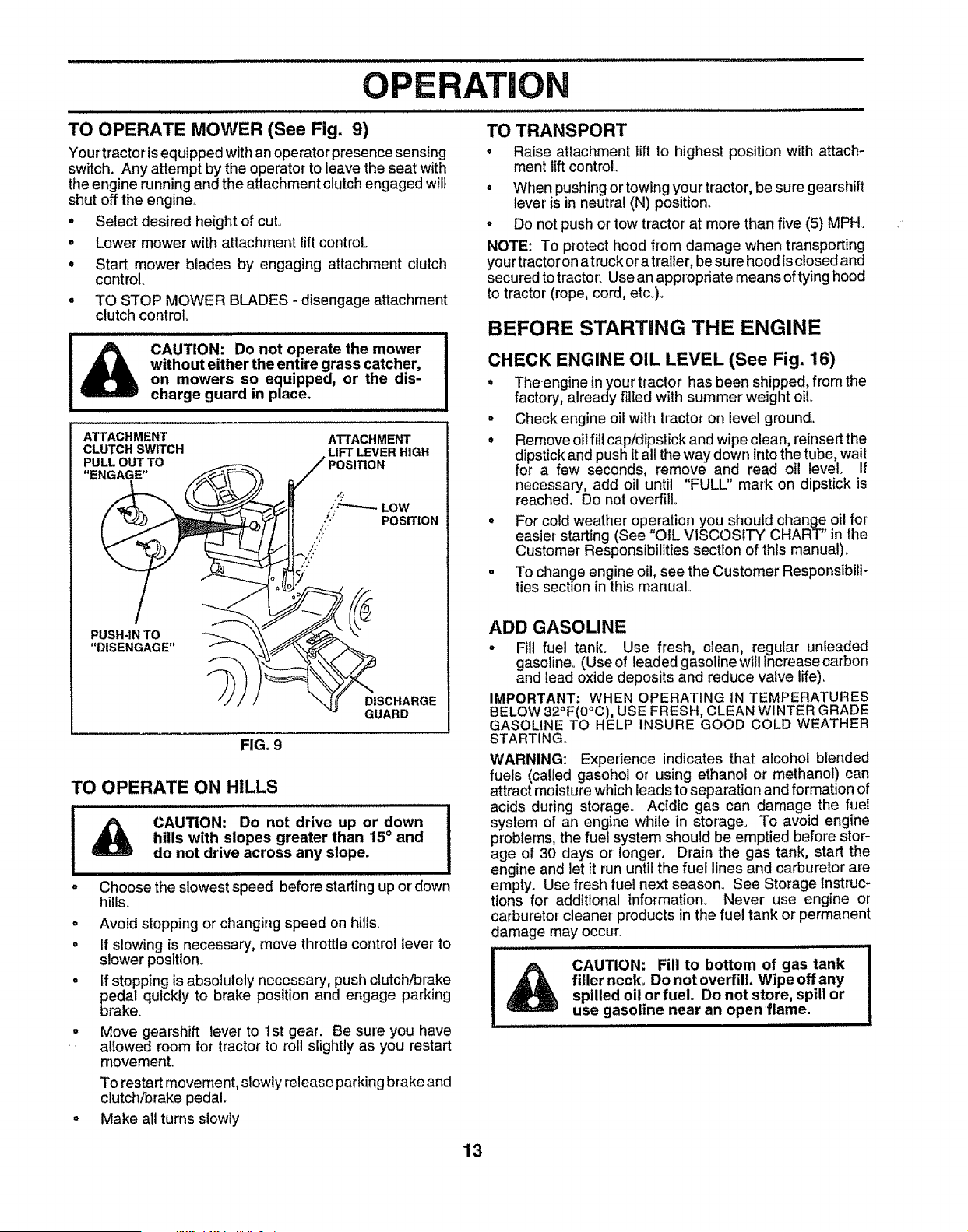
TO OPERATE MOWER (See Fig. 9)
Your tractor isequipped with an operator presencesensing
switch. Any attempt by the operator to leave the seat with
the engine running and the attachment clutch engaged wilt
shut off the engine,.
. Select desired height of cut°
- Lower mower with attachment lift control.
• Start mower blades by engaging attachment clutch
control.
o TO STOP MOWER BLADES- disengage attachment
clutch control
,,,,,,,,,,,,,, ,,, ,,,,,,,,,,,,, ,,,,,,,, ,,,,,,,,,,,,,,,,,,,,,,,,
I& CAUTION: Do not operate the mower
without either the entire grass catcher,
on mowers so equipped, or the dis-
charge guard in place.
, ,,, ,,,,, ,,,, ,, ,,,,,,,,,,,,,
ATTACHMENT
CLUTCH SWITCH
/
PUSH-IN TO
"DISENGAGE"
ATTACHMENT
_/.__ LIFT LEVER HIGH
POSITION
Low
"' POSITION
o!'"
__ _DISCHARGE
GUARD
FIG. 9
TO OPERATE ON HILLS
CAUTION: Do not drive up or down
hills with slopes greater than 15° and
do not drive across any slope.
, ,, ,, , ,,, ,,,,,,,,,,,,,,,,,,,,
Choose the slowest speed before starting up or' down
hills_
° Avoid stopping or changing speed on hills.
• If slowing is necessary, move throttle control lever to
slower position°
° If stopping is absolutely necessary, push clutch/brake
edal quickly to brake position and engage parking
rake,
- Move gearshift lever to 1st gear. Be sure you have
., allowed room for tractor to roll slightly as you restart
movemen[
To restart movement, slowly release parking brake and
clutch/brake pedal.
o Make all turns slowly
TO TRANSPORT
• Raise attachment lift to highest position with attach-
ment lift control,
° When pushing or towing your tractor, be sure gearshift
lever is in neutral (N) position.
° Do not push or tow tractor at more than five (5) MPH,
NOTE: To protect hood f]om damage when transporting
your tractoron atruck or atrailer, be sure hood is closed and
secured to tractor'. Use an appropriate means oftying hood
to tractor (rope, cord, etc..).
BEFORE STARTING THE ENGINE
CHECK ENGINE OIL LEVEL (See Fig. 16)
• Theengine in your tractor has been shipped, from the
factory, already filled with summer' weight oil.
• Check engine oil with tractor on level ground.,
° Remove oil fill cap/dipstick and wipe clean, reinsert the
dipstick and push it all the way down into the tube, wait
for a few seconds, remove and read oil level. If
necessary, add oil until "FULL" mark on dipstick is
reached. Do not overfill.
° For cold weather operation you should change oil for
easier starting (See "OIL VISCOSITY CHART" in the
Customer Responsibilities section of this manual).,
• To change engine oil, see the Customer Responsibili-
ties section in this manual
ADD GASOLINE
o Fill fuel tank° Use fresh, clean, regular unleaded
gasoline., (Use of leaded gasoline will increase carbon
and lead oxide deposits and reduce valve life).
IMPORTANT: WHEN OPERATING IN TEMPERATURES
BELOW 32°F(0°C), USE FRESH, CLEAN WINTER GRADE
GASOLINE TO HELP INSURE GOOD COLD WEATHER
STARTING..
WARNING: Experience indicates that alcohol blended
fuels (called gasohot or using ethanol or methanol) can
attract moisture which leads to separation and formation of
acids during storage° Acidic gas can damage the fuel
system of an engine while in storage. To avoid engine
problems, the fuel system should be emptied before stor-
age of 30 days or longer. Drain the gas tank, start the
engine and let it run until the fuel lines and carburetor are
empty. Use fresh fuel next season_ See Storage lnstruc-
tions for additional information_ Never use engine or
carburetor cleaner products in the fuel tank or permanent
damage may occur.
CAUTION: Fill to bottom of gas tank
filler neck. Do not overfill. Wipe off any
spilled oil or fuel. Do not store, spill or
use gasoline near an open flame.
13
ATION
iul ii i,iii,
TO START ENGINE (See Fig, 8)
When startingengine for the first time or if engine has run
outof fuel, it willtake extra cranking time to move fuel from
the tank to the engine.
• Depress clutch/Drake pedal and set parking brake.
• Place gearshift lever in neutral (N) position.
° Move attachment clutch to "DISENGAGED" position.
. Pull choke control out to choke (l\I) position for cold
engine start° For warm engine start do not use choke
control.
• Move throttle control to midway between fast (._) and
slow (-=_) positions,
• Insert key into ignitionand turn keyclockwiseto"START"
position and release key as soon as engine starts. Do
not run starter continuously for more than fifteen
seconds per minute° If engine does not start after
several attempts, move throttle control to fast (._)
position, wait a few minutes and try again.
• When engine starts, slowly push choke control ino
• Move throttle control to fast (,_) position.
= Allow engine to warm up for a few minutes before
engaging drive or attachments.
NOTE: If at a high altitude (above 3000 feet) or in cold
temperatures (below 32°F), the carburetor fuel mixture
may need to be adjusted for best engine performance. See
"TO ADJUST CARBURETOR" in the Sewice and Adjust-
ments section of this manual.
MOWING TIPS
° Tire chains cannot be used whenthe mower housingis
attached to tractor.
°
°
Mower should be properly leveled for best mowing
performance. See ''TO LEVEL MOWER HOUSING" in
the Service and Adjustments section of this manual.
The left hand side of mower should be used for trim-
mingo
Drive so that clippings are discharged onto the area
that has been cut. Have the cut area to the right of the
machine. This will result in a more even distribution of
clippings and more uniform cutting,
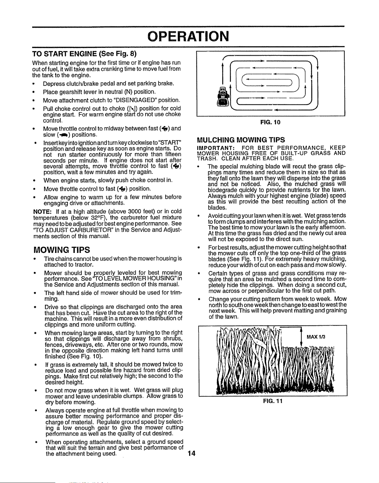
When mowing large areas, start by turningto the right
so that clippings will discharge away from shrubs,
fences, driveways, etc. After one or two rounds, mow
in the opposite direction making left hand turns until
finished (See Fig 10).
If grass is extremely tail, it should be mowed twice to
reduce load and possible fire hazard from dried clip-
dPings.Make first cut relatively high; the second to the
esired height.
Do not mow grass when it is wet° Wet grasswil! plug
mower and leave undesirable clumps, Allow grass to
dry before mowing°
Always operate engine at full throttlewhen mowingto
assure better mowing performance and proper dis-
charge of material° Regulate ground speed by select-
ing a low enough gear to give the mower cutting
performance as well as the quality of cut desired.
When operating attachments, select a ground speed
that will suit the terrain and give best performance of
the attachment being used.
14
f
1
l
FIG. 10
MULCHING MOWING TIPS
IMPORTANT: FOR BEST PERFORMANCE, KEEP
MOWER HOUSING FREE OF BUILT-UP GRASS AND
TRASH_ CLEAN AFTER EACH USE,
° The special mulching blade will recut the grass clip-
pings many times and reduce them in size so that as
they fall onto the lawn they will disperse into the grass
ana not be noticed° Also, the mulched grass will
biodegrade quickly to provide nutrients for the lawn.
Always mulch with your highest engine (blade) speed
as this will provide the best recutting action of the
blades_
• Avoid cutting your lawnwhen it is wet° Wet grass tends
to form clumps and interferes with the mulching action°
The best time to mow your lawn is the early afternoon,
At this time the grass has dried and the newly cut area
wil! not be exposed to the direct sun.
• For best results, adjust the mower cutting height so that
the mower cuts off only the top one-third of the grass
blades (See Fig. 11),, For extremely heavy mulching,
reduce your width of cut on each pass and mow slowly.
- Certain types of grass and grass conditions may re-
quire that an area be mulched a second time to com-
pletely hide the clippings. When doing a second cut,
mow across or perpendicular to the first cut path.
. Change your cutting pattern from week to week. Mow
north to south one weekthen change to east to west the
next week. This will help prevent matting and graining
of the lawn.
FIG. 11
MAX 1/3
I.
F
CUSTOMER BILITIES
MAINTENANCE SCHEDULE /_./_o_/__ "
AS YOU COMPLETE __._._. _/_ ,_,,_j_ _ _@ _ _ ,_._
REGULAR SERVICE ........ __" _ERVlCE DATES
ctieCk Brake Operation If lip 4
T :(:;hock:forLooseFasteners
a Sharpen/Replace Mower Biades t_4 i
c L.b"c"tio"O"a. ....... V' .....t............i 1 1 1 !
"c'heck Battery LevevRecharge ..................... _ i t
m ......... I ..........1 I 1
0 Clean Battery and Terminals _
R
Check Transaxte Cooting
Adjust Blade Belt(s) Tension " ' ' ' ..........'" ' _'
Adjust Motion Drive Bett(s) Tension Ks
Check Engine Oil Level ..........._ . . V 4 . , '.....
Change Engine Q{!
..........................................
_
_
:_'3L
_
E Clean Air Filter _42
a Clean Air Screen _2
G Inspect MuffterlSpa_rk Attester ................................. e#4 : _ .
I Replace Oil Filter (if equipped) _.2
N Clean Engine Cooling Fins $#_2 ......i
Replace Spark Plug _
Replace Air Fifter Paper Cartridge 64#2
Replace Fuel Filter _/
1
1_ Change more ot'[enwhen operating under"a heavy load ot in high amblent temperatures,,
2 - Service more o|ten when operating tn dirty or dusty condllions
3 - tf equipped w_l,helf filter,change oll every 50 hours
4 - Replace blades more often when mowtng Ir_sandy soil,
5- If equipped with adjustable system,
6- Not requ#ed if equipped with matntenance4ree battery
7 - Tighten front axle plvet belt to 35 ft.4bs maxtmum
Do not ove_llghten
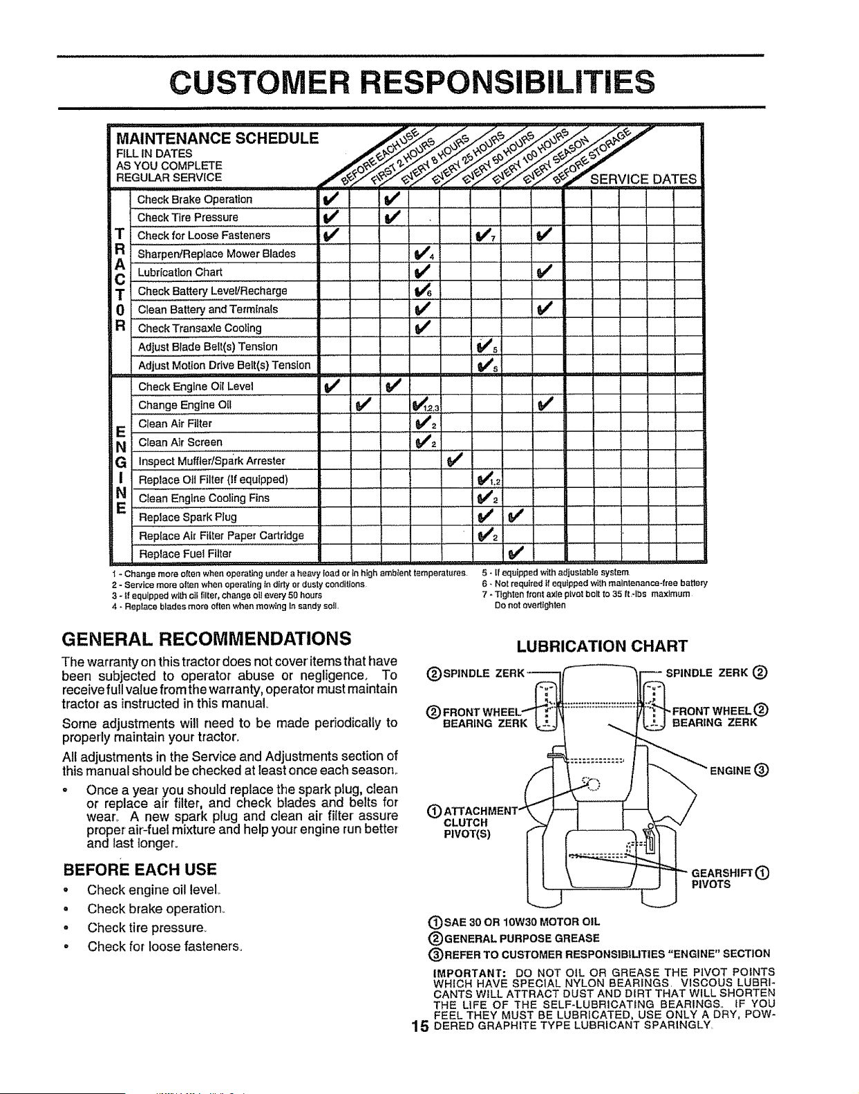
GENERAL RECOMMENDATIONS
The warranty on this tractor does not cover' items that have
been subjected to operator abuse or negligence, To
receive full value from the warranty, operator must maintain
tractor as instructed in this manual,
Some adjustments will need to be made periodicalfy to
properly maintain your tractor°
All adjustments in the Service and Adjustments section of
this manual should be checked at least once each season,,
- Once a year you should replace the spark plug, dean
or replace air' filter, and check blades and belts for
wear_ A new spark plug and clean air filter assure
proper air-fuel mixture and help your engine run better
and last longeL
BEFORE EACH USE
o Check engine oil level
= Check brake operation,.
° Check tire pressure,,
• Check for loose fasteners.
(_) SPINDLE
LUBRICATION CHART
SPINDLE ZERK (_
(_) FRONT
BEARING ZERK BEARING ZERK
@
@
CLUTCH
PIVOT(S)
I PIVOTS {3)
J
(_SAE 30 OR 10W30 MOTOR OIL
(_)GENERAL PURPOSE GREASE
(_)REFER TO CUSTOMER RESPONSIBILITIES "ENGINE" SECTION
IMPORTANT: DO NOT OIL OR GREASE THE PIVOT POINTS
WHICH HAVE SPECIAL NYLON BEARINGS, VISCOUS LUBRI-
CANTS WILL ATTRACT DUST AND DIRT THAT WILL SHORTEN
THE LiFE OF THE SELF-LUBRICATING BEARINGS,, IF YOU
FEEL THEY MUST BE LUBRICATED, USE ONLY A DRY, POW-
1 5 DERED GRAPHITE TYPE LUBRICANT SPARINGLY,
CUSTOMER RESPONSIBILITIES
TRACTOR
Always observe safety rules when performing any mainte-
nance,
BRAKE OPERATION
If tractor requires more than six (6) feet stopping distance
at highspeed inhighest gear, thenbrake mustbe adjusted,,
(See "TO ADJUST BRAKE" in the Service and Adjust-
ments section of this manual).
TIRES
o Maintain proper air pressure in all tires (See "PROD-
UCT SPECIFICATIONS" on page 3 of this manual).
• Keep tires free of gasoline, oil, or insectcontrolchemi-
cals which can harm rubber.
• Avoid stumps, stones, deep ruts, sharp objects and
other hazards that may cause tire damage°
BLADE CARE
For best results mower blades must be kept sharp° Re-
place bent or damaged blades°
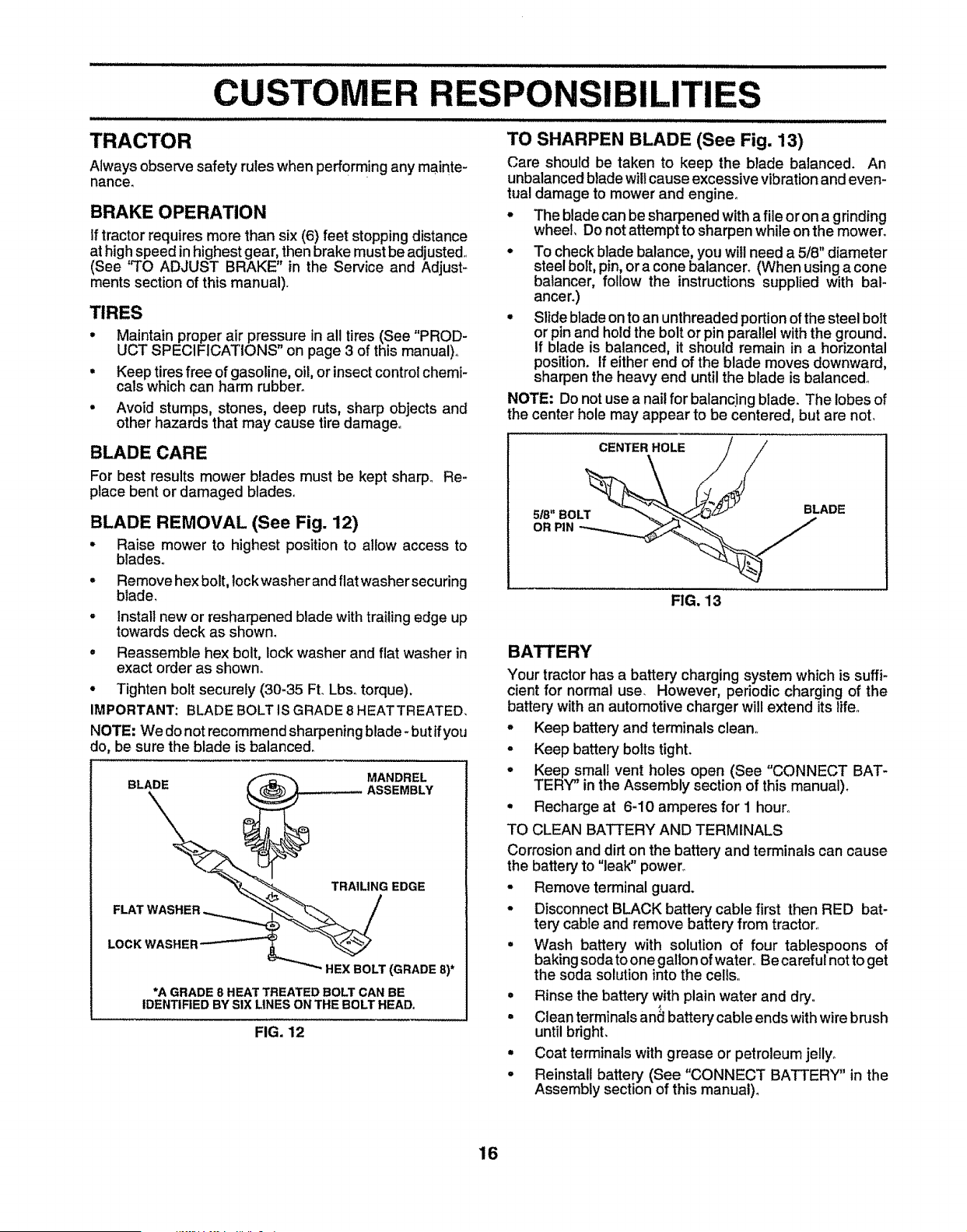
BLADE REMOVAL (See Fig. 12)
° Raise mower to highest position to allow access to
blades_
° Remove hex bolt, lockwasherand flat washersecuring
blade,
- Install new or resharpened blade with trailing edge up
towards deck as shown,
° Reassemble hex bolt, lock washer and flat washer in
exact order as shown.
° Tighten bolt securely (30-35 FL Lbso torque).
IMPORTANT: BLADE BOLT IS GRADE 8 HEATTREATED,
NOTE; We do not recommend sharpening blade- but ifyou
do, be sure the blade is balanced.
BLADE
MANDREL
TRAILING EDGE
FLAT WASHER
LOCK WASHER
HEX BOLT (GRADE 8)*
*A GRADE 8 HEAT TREATED BOLT CAN BE
IDENTIFIED BY SIX LINES ON THE BOLT HEAD,
FIG. 12
TO SHARPEN BLADE (See Fig. 13)
Care should be taken to keep the blade balanced. An
unbalanced blade willcause excessive vibration and even-
tual damage to mower and engine°
° The blade can be sharpened with a file or on a gdnding
wheel, Do not attempt to sharpen while on the mower.
° To check blade balance, you will need a 5/8" diameter
steel boIt, pin, or a cone balancer. (When using a cone
balancer, follow the instructions supplied with bal-
ancer.)
• Slide blade on to an unthreaded portionof the steel bolt
or pin and holdthe bolt or pin parallel with the ground.
If blade is balanced, it should remain in a horizontal
position. If either end of the blade moves downward,
sharpen the heavy end until the blade is balanced_
NOTE: Do not use a nail for balancing blade. The lobes of
the center hole may appear to be centered, but are not.
CENTER HOLE
5/8" BOLT
OR PIN
BLADE
FIG. 13
BATTERY
Your tractor has a battery charging system which is suffi_
cient for normal use. However, periodic charging of the
battery with an automotive charger will extend its lifeo
• Keep battery and terminals clean,,
° Keep battery bolts tight.
° Keep small vent holes open (See "CONNECT BAT-
TERY" inthe Assembly section of this manual).
• Recharge at 6-10 amperes for 1 hour.,
TO CLEAN BATTERY AND TERMINALS
Corrosion and dirt on the battery and terminals can cause
the batteryto "leak" power°
• Remove terminal guard.
• Disconnect BLACK battery cable first then RED bat-
tery cable and remove battery from tractor.,
• Wash battery with solution of four tablespoons of
bakingsoda to onegallon ofwater,, Be careful notto get
the soda solution into the cells,,
° Rinse the battery with plain water and dry°
. Clean terminalsand batterycable ends withwire brush
untilbright.
• Coat terminals with grease or petroleum jelly°
. Reinstall battery (See "CONNECT BATTERY" in the
Assembly section of this manual)°
16
/J //i,/i, i/,Jl,Jl,Jl/,/,Jl,Jl,/,,JllJl,JlJlJl,,/,/,/,JlJlJl,/,/,/,/i,/,/,1/11,
CUSTOMER
V-BELTS
Check V-belts for deterioration and wear after 100 hours of
operation and replace if necessary, The belts are not
adjustable_Replace belts if they begin to slip from wear'.
TRANSAXLE COOLING
Keep transaxle free from build-up of dirt and chaff which
can restrictcooling.
ENGINE
IBILITIES
OIL FILL
CAP/DIPSTICK
OIL DRAIN
PLUG
LUBRICATION
Only use high quality detergent oil rated with API service
classification SForSG_ Select the oil's SAEviscosity grade
according to your expected operating temperature.
SAE VISCOSITY GRADES
°F :_o_......oo.......30" 3ao 40" 60° 80° Ioo"
'_C -30 _' -20 _ -_0 = 0° 10" 20" 30 ° 40 =
TEMPERATURE RANGE ANTICIPATED BEFORE NEXT OIL CHANGE
FIG. 14
NOTE: Although multi-viscosity oils (5W30, t0W30 etc.)
improve starting in cold weather, these multi-viscosity oils
will result in increased oil consumption when used above
32°F. Check your' engine oil level more frequently to avoid
possible engine damage from running low on oil.
Change the oil after the first two hours of operation and
every 50 hours thereafter or at least once a year if the
tractor is not used for 50 hours in one year.
Check the crankcase oil level before starting the engine
and after each eight (8) hours of operation, Tighten oil fill
cap/dipstick securely each time you check the oil level,,
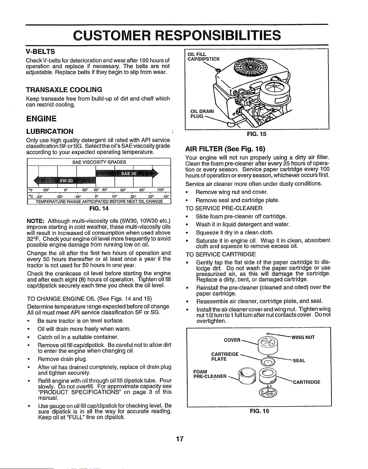
TO CHANGE ENGINE OIL (See Figs,, 14 and 15)
Determine temperature range expected before oil change_
All oil must meet API service classification SF or SG.
• Be sure tractor is on level surface.
o Oil will drain more freely when warm,,
= Catch oil in a suitable container°
= Remove oil fill cap/dipstick_ Be careful not to allow dirt
to enter the engine when changing oil.
• Remove drain plug.
° After oil has drained completely, repiace oil drain plug
and tighten securely_
° Refill engine with oil through oil fill dipstick tube. Pour
slowly. Do not overfill,, For approximate capacity see
"PRODUCT SPECIFICATIONS" on page 3 of this
manual,
= Use gauge on oil fill cap/dipstick for checking revel, Be
sure dipstick is in aH the way for accurate reading,_
Keep oil at "FULL" line on dipstick,,
FIG. 15
AIR FILTER (See Fig. 16)
Your engine will not run properly using a dirty air filteL
CIean the foam pre-cleaner after every 25 hours of opera-
tion or'every season° Service paper cartridge every I00
hoursof operation or every season, whichever occurs first.
Service air cleaner more often under dust/conditions.
o Remove wing nut and cover..
• Remove sea[ and cartridge plate_
TO SERVICE PRE-CLEANER
, Slide foam pre-cleaner off cartridge,.
• Wash it in liquid detergent and water°
o Squeeze it dry in a clean cloth.
• Saturate it in engine oHo Wrap it in clean, absorbent
cloth and squeeze to remove excess oil
TO SERVICE CARTRIDGE
• Gently tap the flat side of the paper cartridge to dis-
lodge dirt. Do not wash the paper cartridge or use
pressurized air, as this will damage the cartridge..
Replace a dirty, bent, or damaged cartridge.,
° Reinstall the pre-cteaner (cleaned and oiled) over the
paper cartridge,.
• Reassemble air' cleaner, cartridge plate, and seal.
• Install the air cleaner cover and wing nut° Tighten wing
nut 1/2 turnto I ful! turn after nut contacts cover° Do not
overtighten.
FIG. 16
17
CUSTOMER R NSIBILITIES
i ill i iL llllllllll
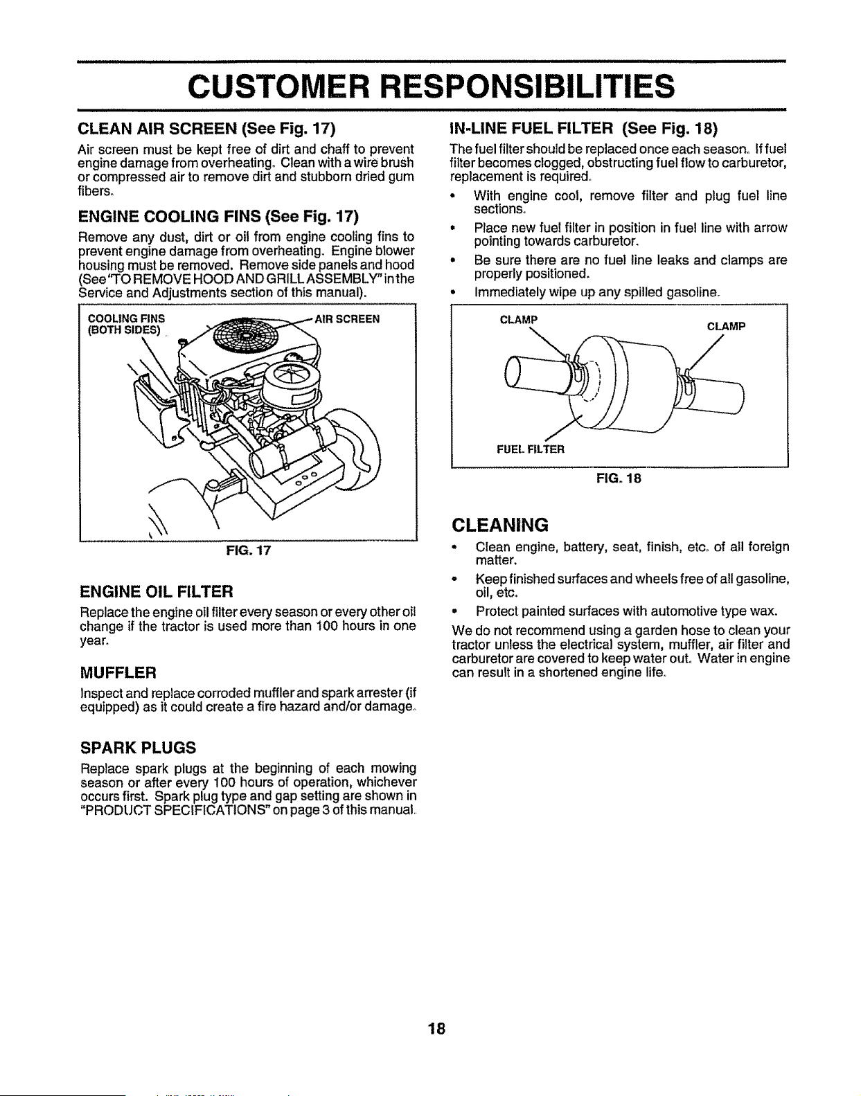
CLEAN AIR SCREEN (See Fig. 17)
Air screen must be kept free of dirt and chaff to prevent
enginedamage from overheating, Clean with awire brush
or compressed air to remove dirt and stubborn dried gum
fibers_
ENGINE COOLING FINS (See Fig. 17)
Remove any dust, dirt or oil from engine cooling fins to
prevent engine damage from overheating, Engine btower
housingmust be removed. Remove side panels and hood
(See'q'O REMOVE HOOD AND GRILL ASSEMBLY"inthe
Service and Adjustments section of this manual).
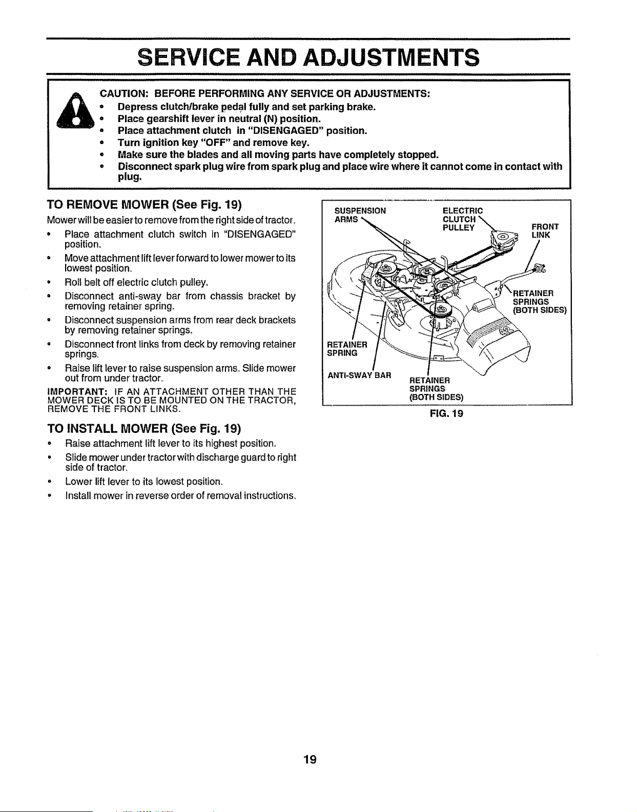
IN-LINE FUEL FILTER (See Fig. 18)
The fuel filter should be replaced once each season° Iffuel
filter becomes clogged, obstructing fuel flow to carburetor,
replacement is required.
• With engine cool, remove filter and plug fuel line
sections.
• Place new fuel filter in position in fuel line with arrow
pointing towards carburetor.
° Be sure there are no fue! line leaks and clamps are
properly positioned.
• Immediately wipe up any spilled gasoline.
COOLING FINS SCREEN
(BOTH SIDES)
\
FIG. 17
ENGINE OIL FILTER
Replace the engine oilfilter every season or every other oil
change if the tractor is used more than 100 hours in one
yearn
MUFFLER
Inspectand replace corroded muffler and spark arrester (if
equipped) as it could create a fire hazard and/or damage°
CLAMP CLAMP
FUEL FILTER
FIG. 18
CLEANING
o Clean engine, battery, seat, finish, etc° of all foreign
matter.
• Keep finished surfaces and wheels free of all gasoline,
oil, etc.
° Protect painted surfaces with automotive type wax.
We do not recommend using a garden hose to clean your
tractor unless the electrical system, muffler, air filter and
carburetor are covered to keep water out, Water in engine
can result in a shortened engine life.
SPARK PLUGS
Replace spark plugs at the beginning of each mowing
season or after every i00 hours of operation, whichever
occurs first. Spark plug type and gap setting are shown in
"PRODUCT SPECIFICATIONS" on page 3 of this manual
18
SERVICE AND ADJ
illl iillll ii ii ,,,,,, ,,,,,,,,,,, , ,,,, ,,, ,,, ,,, ,, , , ,,,,,,,,,, ,,,,,,,, .............................................. ,,,,,,,,,,
a
Q
@
o
CAUTION: BEFORE PERFORMING ANY SERVICE OR ADJUSTMENTS;
Depress clutcldbrakepedal fully and set parking brake.
Place gearshift lever in neutral (N) position.
Place attachment clutch in "DISENGAGED" position.
Turn ignition key "OFF" and remove key.
Make sure the blades and all moving parts have completely stopped.
Disconnect spark plug wire from spark plug and place wire where it cannot come in contact with
plug,
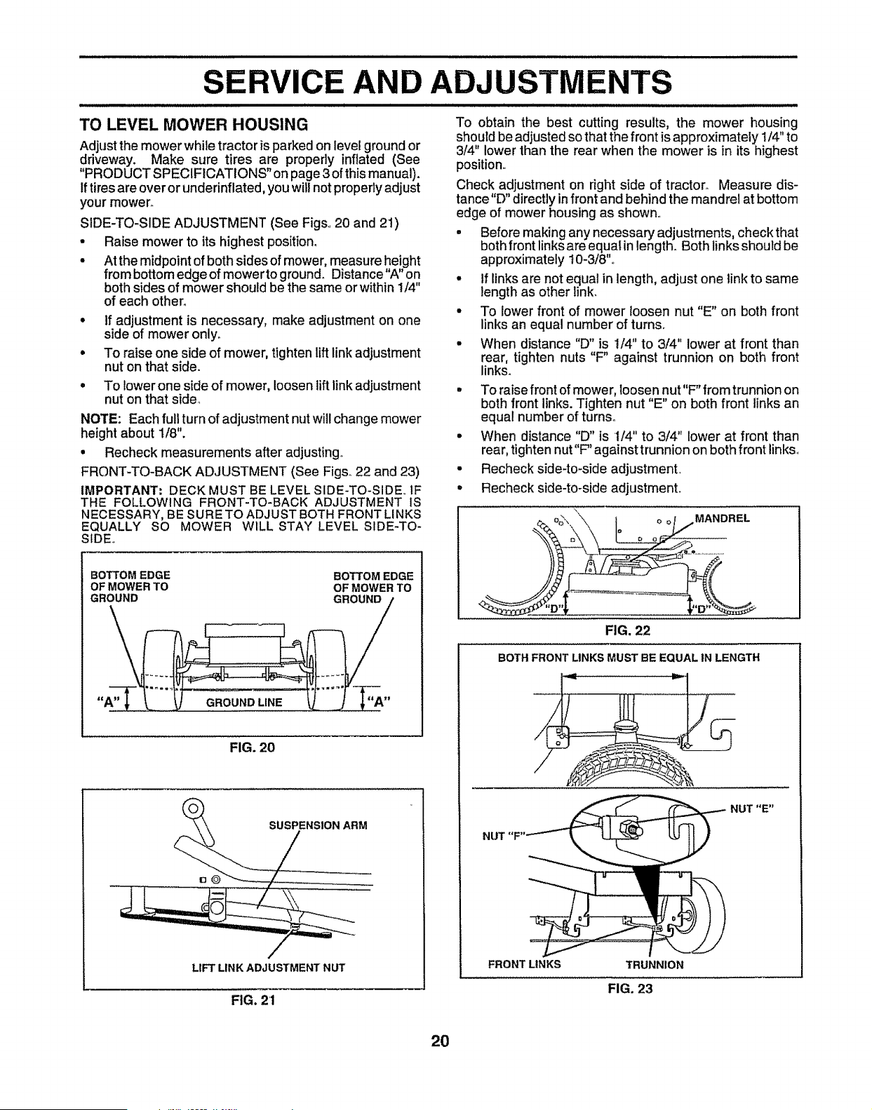
TO REMOVE MOWER (See Fig. 19)
Mower wiltbe easier to remove from the right side of tractor',
• Place attachment clutch switch in "DISENGAGED"
position°
• Move attachment liftleverforward to tower mower to its
lowest position.
• Roll belt off electric clutch pulley.
= Disconnect anti-sway bar from chassis bracket by
removing retainer spring_
, Disconnect suspension arms from rear deck brackets
by removing retainer springs°
° Disconnect front links from deck by removing retainer
springs,
° Raise lift lever to raise suspension arms,, Slide mower
out from under tractor°
IMPORTANT= IF AN ATTACHMENT OTHER THAN THE
MOWER DECK 1STO BE MOUNTED ON THE TRACTOR,
REMOVE THE FRONT LINKS,,
TO INSTALL MOWER (See Fig. 19)
o Raise attachment lift lever to its highest position,,
o Slide mower under tractorwith discharge guardto dght
side of tractor_
° Lower lift lever to its lowest position.
o installmower in reverse orderof removal instructions_
SUSPENSION ELECTRIC
ARMS CLUTCH
PULLEY
FRONT
LINK
SPRINGS
BOTH SIDES)
RETAINER
SPRING
ANTI-SWAY BAR
RETAINER
SPRINGS
(BOTH SIDES)
FIG. 19
19
SERVICE AND ADJUSTMENTS
TO LEVEL MOWER HOUSING
Adjust the mower while tractor is parked on level ground or
driveway. Make sure tires are properly inflated (See
"PRODUCT SPECIFICATIONS" on page 3 of this manual).
If tires are over or underinflated, you will not properly adjust
your mower.
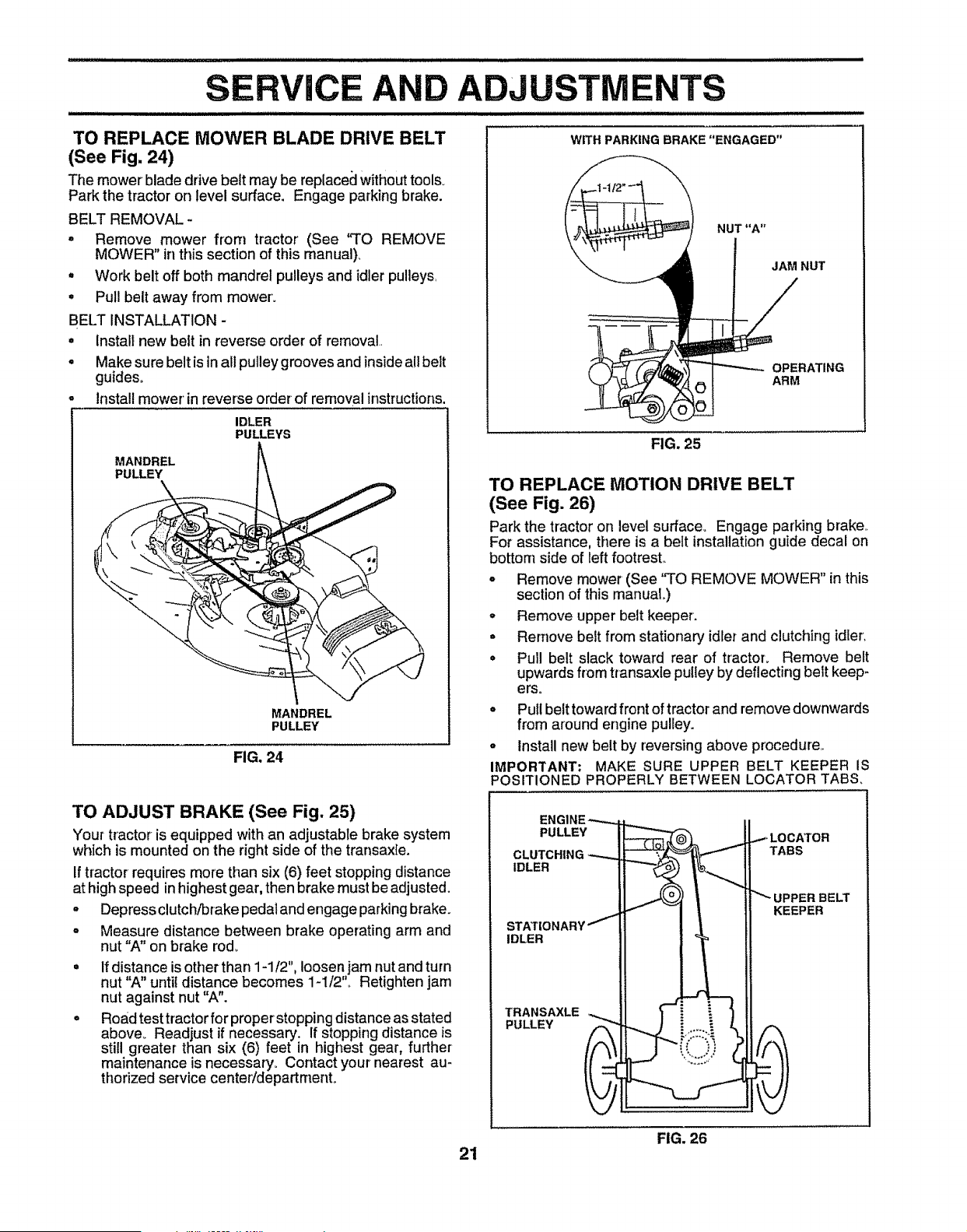
SIDE-TO-SIDE ADJUSTMENT (See Figs..20 and 2t)
• Raise mower to its highest position.
• At the midpoint of both sides of mower, measure height
from bottom edge of mowerto ground° Distance "A" on
both sides of mower should be the same or within 1/4"
of each other.
• If adjustment is necessary, make adjustment on one
side of mower only.
• To raise one side of mower, tighten liftlink adjustment
nut on that side.
o
To lowerone side of mower, loosen liftlink adjustment
nut on that sider
NOTE: Each full turn of adjustment nut will change mower
height about 1/8".
= Recheck measurements after adjusting°
FRONT-TO-BACK ADJUSTMENT (See Figs° 22 and 23)
IMPORTANT; DECK MUST BE LEVEL SIDE-TO-SIDE. IF
THE FOLLOWING FRONT-TO-BACK ADJUSTMENT IS
NECESSARY, BE SURE TO ADJUST BOTH FRONT LINKS
EQUALLY SO MOWER WILL STAY LEVEL SIDE-TO -
SIDE..
BOTTOM EDGE BOTTOM EDGE
OF MOWER TO OF MOWER TO
GROUND
"A" -"_"
FIG. 20
LIFT LINK ADJUSTMENT NUT
FIG. 21
To obtain the best cutting results, the mower housing
should be adjusted so that the front is approximately 1/4" to
3/4" lower than the rear when the mower is in its highest
position,.
Check adjustment on right side of tractor. Measure dis-
tance"D" directly in front and behind the mandrel at bottom
edge of mower housing as shown..
• Before making any necessary adjustments, checkthat
both front links are equal in length. Both links should be
approximately 10-3/8".,
. tf links are not equal in length, adjust one link to same
length as other link.
• To lower front of mower loosen nut "E" on both front
links an equal number of turns,
• When distance "D" is t/4" to 3/4" lower at front than
rear, tighten nuts "F" against trunnion on both front
links.
• To raise front of mower, loosen nut"F" fromtrunnion on
both front links. Tighten nut "E" on both front links an
equal number of turns.
. When distance "D" is t/4" to 3/4" lower at front than
rear, tighten nut"F" against trunnion on both front links_
• Recheck side-to-side adjustment.
° Recheck side-to-side adjustment.
MANDREL
FIG. 22
BOTH FRONT LINKS MUST BE EQUAL IN LENGTH
NUT "E"
FRONT LINKS TRUNNION
FIG. 23
2O
RViCE AND ADJUSTMENTS
TO REPLACE MOWER BLADE DRIVE BELT
(See Fig. 24)
The mower blade drive belt may be replaceclwithouttools_
Park the tractor on level surface. Engage parking brake.
BELT REMOVAL -
. Remove mower from tractor (See 'qro REMOVE
MOWER" in this section of this manual),
• Work belt off both mandrel pulleys and idler pulleys,
° Pull belt away from mower'.
BELT INSTALLATION -
• install new belt in reverse order of removal..
° Make sure belt is in all pulley grooves and inside all belt
guides°
install mower' in reverse order of removal instructions.
IDLER
PULLEYS
MANDREL
PULLEY
MANDREL
PULLEY
FIG. 24
TO ADJUST BRAKE (See Fig. 25)
Your tractor is equipped with an adjustable brake system
which is mounted on the rightside of the transaxle.
If tractor requires more than six (6) feet stopping distance
athigh speed inhighest gear, then brake must be adjusted.
° Depressclutch/brake pedal and engage parkingbrake.
o Measure distance between brake operating arm and
nut"A" on brake rod.
• If distance isother than 1-1/2", loosen jam nut andturn
nut"A" untildistance becomes 1-1/2",, Retighten jam
nut against nut"A".
° Road testtractorfor properstopping distanceas stated
above. Readjust if necessary. If stoppingdistance is
still greater than six (6) feet in highest gear, further
maintenance is necessary° Contact your nearest au-
thorized service center/departmento
WITH PARKING BRAKE "ENGAGED"
NUT "A"
JAM NUT
OPERATING
ARM
FIG, 25
TO REPLACE MOTION DRIVE BELT
(See Fig. 26)
Park the tractor on level surface° Engage parking brake,.
For assistance, there is a belt installation guide decal on
bottom side of left footrest,,
° Remove mower (See "TO REMOVE MOWER" in this
section of this manuaL)
° Remove upper belt keeper.
= Remove belt from stationary idlerand clutching idler,
° Pull belt slack toward rear of tractor° Remove belt
upwards from transaxle pulley by deflecting belt keep-
ers,
° Pull belt toward front oftractor and remove downwards
from around engine pulley.
o Install new belt by reversing above procedure,.
IMPORTANT; MAKE SURE UPPER BELT KEEPER IS
POSITIONED PROPERLY BETWEEN LOCATOR TABS_
21

SERVICE AND ADJUSTMENTS
TO ADJUST STEERING WHEEL ALIGNMENT
If steering wheel crossbarsare not horizontal(left to right)
whenwheels are positionedstraightforward, removeSteel-
ing wheel and reassemble per instructionsinthe Assembly
section of this manual..
FRONT WHEEL TOE-IN/CAMBER
The front wheel toe-in and camber are not adjustable on
your tractor.. If damage has occurred to affect the front
wheel toe-in or camber, contact your nearest authorized
service center/departmento
TO REMOVE WHEEL FOR REPAIRS
(See Fig, 27)
• Block up axle securely_
• Remove axle cover, retaining ring and washers to allow
wheel removal (rear wheel contains a square key _Do
not lose).
• Repair tire and reassemble.
• On rear wheels only: align grooves in rear wheel hub
and axle_ Insert square key°
= Replace washers and snap retaining ring securely in
axle groove°
Replace axle cover..
WASHERS
AXLE eOVER _ SQUARE KEY
(REAR WHEEL ONLY)
FIG. 27
TO START ENGINE WITH A WEAK BATTERY
(See Fig. 28)
==.lA CAUTIONS: Lead-acid batteries gener- ..........
A • ateexplosivegases. Keepsparks, flame
and smoking materials away from bat-
teries. Always wear eye protection
........ when around batteries.
if your battery is too weak to start the engine, it should be
recharged, If "jumper cables" are used for emergency
starting, follow this procedure:
IMPORTANT: YOUR TRACTOR tS EQUIPPED WITH A 12
VOLT NEGATIVE GROUNDED SYSTEM. THE OTHER
VEHICLE MUST ALSO BE A 12 VOLT NEGATIVE
GROUNDED SYSTEM. DO NOT USE YOUR TRACTOR
BATTERY TO START OTHER VEHICLES°
TO ATTACH JUMPER CABLES -
• Connect each end of the RED cable to the POSITIVE
(+) terminal of each battery, taking care not to short
against chassis.
• Connect one end of the BLACK cable to the NEGA-
TIVE (-) terminal of fully charged battery°
• Connect the other end of the BLACK cable to good
CHASSIS GROUND, away from fuel tank and battery.
TO REMOVE CABLES, REVERSE ORDER -
• BLACK cable first from chassis and then from the fully
charged battery.
• RED cable last from both battedeso
_[ ,,..:ll J
;oLT
FIG. 28
TO REPLACE HEADLIGHT BULB
• Raise hood..
= Pull bulb holder out of the hole in the backside of the
griiL
o Replace bulb in holder and push bulb holder securely
back into the hole in the backside of the grille
• Close hood.
INTERLOCKS AND RELAYS
Loose or damaged wiring may cause your tractor to run
poorly, stop running, or prevent it from starting.
• Check wiring., See electrical wiring diagram in the
Repair Parts section of this manual
TO REPLACE FUSE
Replace with 30 amp automotive-type plug-in fuse. The
fuse holder is located behind the dash.
TO REMOVE HOOD AND GRILL ASSEMBLY
(See Fig. 29)
• Raise hood_
• Unsnap headlight wire connector,
• Stand in front of tractor° Grasp hood at sides, tilt toward
engine and lift off of tractor,
• To replace, reverse above procedure,
HOOD
HEADLIGHT
WIRE
CONNECTOR
22 FIG. 29
ENGINE
SERVICE AND ADJUSTMENTS
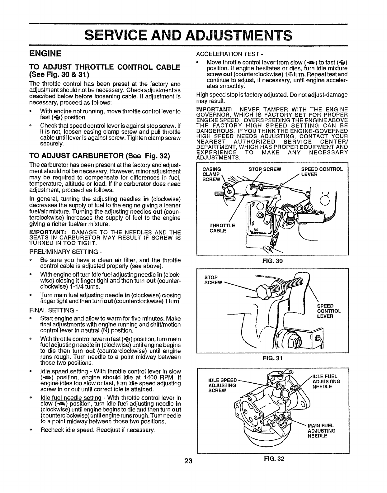
TO ADJUST THROTTLE CONTROL CABLE
(See Fig. 30 & 31)
The throttle control has been preset at the factory and
adjustment should not be necessary_ Checkadjustment as
described below before loosening cable. If adjustment is
necessary, proceed as follows:
. With engine not running, move throttle control lever to
fast (._) position_
= Check that speed control lever'is against stop screw. If
it is not, loosen casing clamp screw and pul! throttle
cable until lever is against screw_Tighten clamp screw
securely.
TO ADJUST CARBURETOR (See Fig. 32)
The carburetor has been present at the factory and adjust-
ment should not be necessary°However, minor adjustment
may be required to compensate for differences in fuel,
temperature, altitude or loadoIf the carburetor does need
adjustment, proceed as follows:
In general, turning the adjusting needles in (clockwise)
decreases the supply of fuel to the engine givinga leaner
fuel/air mixture° Turning the adjustingneedles out (coun-
terclockwise) increases the supply of fuel to the engine
giving a richer fuel/air mixture.
IMPORTANT: DAMAGE TO THE NEEDLES AND THE
SEATS IN CARBURETOR MAY RESULT IF SCREW IS
TURNED IN TOO TIGHT.
PRELIMINARY SETTING -
° Be sure you have a clean ah filter, and the throttle
control cable is adjusted properly (see above).
o With engine off turn idle fuel adjusting needle in (clock-
wise) closing it finger tight and then turn out (counter-
clockwise) 1-1/4 turns.
= Turn main fuel adjusting needle in (clockwise) closing
finger tight and then turn out (counterclockwise) t turn,
FINAL SETTING -
= Start engine and allow to warm for five minutes. Make
final adjustments with engine running and shift/motion
control lever in neutral (N) position.
° With throttle control lever in fast (,_) position,turn main
fuel adjusting needle in (clockwise) until engine begins
to die then turn out (counterclockwise) until engine
runs rough. Turn needle to a point midway between
those two positions,
• Id!e speed setting - With throttle control lever in slow
(.,=_) position, engine should idle at 1400 RPM. If
engine idles too slow or fast, turn idle speed adjusting
screw in or out until correct idle is attained.
° Idle fuel needle setting - With throttle control lever in
slow (,_) position, turn idle fuel adjusting needle in
clockwise) until engine begins to die and then turn out
counterclockwise) until engine runsrough. Turn needle
to a point midway between those two positions.
° Recheck idle speed. Readjust if necessary.
ACCELERATION TEST -
o Move throttle control lever from slow (,,=_) to fast (=¢e)
position. If engine hesitates or dies, turn idle mixture
screw out (counterclockwise) 1/8 turn° Repeat test and
continue to adjust, if necessary, until engine acceler-
ates smoothly°
High speed stop is factory adjusted. Do not adjust-damage
may result.
IMPORTANT: NEVER TAMPER WITH THE ENGINE
GOVERNOR, WHICH IS FACTORY SET FOR PROPER
ENGINE SPEED. OVERSPEEDING THE ENGINE ABOVE
THE FACTORY HIGH SPEED SETTING CAN BE
DANGEROUS. IFYOU THtNKTHE ENGINE-GOVERNED
HIGH SPEED NEEDS ADJUSTING, CONTACT YOUR
NEAREST AUTHORIZED SERVICE CENTER/
DEPARTMENT, WHICH HAS PROPER EQUIPMENT AND
EXPERIENCE TO MAKE ANY NECESSARY
ADJUSTMENTS.
CASING STOP SCREW SPEED CONTROL
CLAMP LEVER
THROTTLE
CABLE
FIG. 30
STOP
SCREW
SPEED
CONTROL
LEVER
FIG.31
___ /IDLE FUEL
._'_, \/ ADJUSTING
"__J,7 NEEDLE
23 FIG. 32
ill,,,,,,,,,,,,,,,,,, , ,,,,,, , ,,,,, ........................................
STORAGE
Immediately prepare your tractor for storage at the end of
the season or if the tractor will not be used for 30 days or
more_ _
CAUTION: Never store the tractor with
gasoline in the tank inside a building
where fumes may reach an open flame
or spark, Allow the engine to cool
before storing in any enclosure.
i=ll,=l=l== =l =l = Li i i =l =ll i L
TRACTOR
o
o
Remove mower from tractor for winter storage. When
mower is to be stored for a period of time, clean it thor-
oughly, remove all dirt, grease, leaves, etco Store in a
clean, dry area.
• Clean entire tractor (See"CLEAN1NG" inthe Customer
Responsibilities section of this manual).
• Inspect and replace belts, if necessary (See belt re-
placement instructions in the Service and Adjustments
section of this manual)°
Lubricate as shown in the Customer Responsibilities
section of this manual.
Be sure that all nuts, bolts and screws are securely
fastened, inspect moving parts for damage, breakage
and wear. Replace if necessary.
Touch up all rusted or chipped paint surfaces; sand
lightly before painting.
BATTERY
• Fully charge the battery for storage.
, After a period of time in storage, battery may require
recharging.
• To help prevent corrosion and power leakage during
long periods of storage, battery cables should be
disconnectedand battery cleaned thoroughly(see"TO
CLEAN BATTERY AND TERMINALS in the Cus-
tomer Responsibilitiessection of this manual).
• After cleaning, leave cables disconnected and place
cableswhere they cannot come incontact withbattery
terminals°
• Be sure batter_j drain tube is securely attached..
• If battery is re_noved from tractor for storage, do not
store battery directly on concrete or damp surfaces°
ENGINE
FUEL SYSTEM
IMPORTANT: IT tS IMPORTANT TO PREVENT GUM
DEPOSITS FROM FORMING IN ESSENTIAL FUEL
SYSTEM PARTS SUCH AS CARBURETOR, FUEL FILTER,
FUEL HOSE, OR TANK DURING STORAGE. ALSO,
EXPERIENCE INDICATES THAT ALCOHOL BLENDED
FUELS (CALLED GASOHOL OR USING ETHANOL OR
METHANOL) CAN ATTRACT MOISTURE WHICH LEADS
TO SEPARATION AND FORMATION OF ACIDS DURING
STORAGE,. ACIDIC GAS CAN DAMAGE THE FUEL
SYSTEM OF AN ENGINE WHILE IN STORAGE.
• Drain the fuel tank,
• Start the engine and let it run until the fuel lines and
carburetor are empty.
• Never use engine orcarburetorcleaner products in the
fuel tank or permanent damage may occur.
= Use fresh fuel next season.
NOTE: Fuel stabilizer is an acceptable alternative in
minimizing the formation of fuel gum deposits during stor-
age. Add stabilizer to gasoline in fue! tank or storage
container,, Always follow the mix ratio found on stabilizer
container. Run engine at least 10 minutes after adding
stabilizer to allow the stabilizer to reach the carburetor. Do
not drain the gas tank and carburetor if using fuel stabiiizero
ENGINE OIL
Drain oil (with engine warm) and replace with clean engine
oi!. (See "ENGINE" in the Customer Responsibilities
section of this manual).
CYLINDERS
° Remove spark plug(s).
• Pour one ounce of oil through spark plug hole(s) into
cylinder(s).
• Turn ignition key to"START" position fora few seconds
to distribute oil.
• Replace with new spark plug(s).
OTHER
° Do not store gasoline from one season to another.
• Replace your gasoline can if your can starts to rust.
Rust and/or dirt in your gasoline will cause problems.
• If possible, store your tractor indoors and cover it to
give protectionfrom dust and dirt.
• Cover your tractorwith a suitable protective cover that
does not retain moisture_ Do not use plastic. Plastic
cannot breathe which allows condensation to form and
will cause your tractor to rust.
IMPORTANT: NEVER COVER TRACTOR WHILE ENGINE
AND EXHAUST AREAS ARE STILL WARM..
24

TROU COTING POINTS
PROBLEM
Wlllnot start
JLIIIIiiii
Engine will not turn over
Engine clicks but will not
start
Loss of power
Excessive vibration
CAUSE
1, Out of fuel.
2 Engine not "CHOKED" properly,
3. Engine flooded.
4 Bad spark plug,
5 Dirty air filter,
6, Dirty fuel filter,
7, Water in fuel,
B. Loose or damaged wirtng,
9, Carburetor out of adiustment
I0. Engine valves out of adjustment,.
1. Dirty air filter,
2, Bad spark plug,,
3. Weak or dead battery
4, Dirty fuel filter.
5. Stale or dirty fuel.
6. Loose or damaged wtdng.
7. Carburetor out of adjustment
8, Engine valves out of adjustment.
1 Clutch/brake pedal not depressed
2 Attachment clutch is engaged
3 Weak or dead battery
4 Blown fuse,
5 Corroded battery termtnals.
6 Loose or damaged widng
7 Faulty Ignition switch.
8, Faulty solenoid or starter,
9, Faulty operator presence switch(es)
1_ Weak or dead battery
2 Corroded battery terminals
3 Loose or damaged wiring
4 Faulty solenoid or starter,.
1,. Cutting too much grassltoo fasL
2 Throttle in "CHOKE" position.
3, Build.up of grass, leaves and trash under mower,.
4, Dirty air filter.
5, Low o]1level/dirty oil
6 Faulty spark plug
7, Dirty fuel filter.
8 Stale or dirty fuel
9 Water in fuel,.
10 Spark plug wire loose.
11. Dirty engine air screen/fins..
12 Dirtylclogged muffler,.
13 Loose or damaged widng,
14,. Carburetor out of adjustment
15, Engine valves out of adjustment.
llll llll i ,lllll,
1o Worn, bent or loose blade,
2, Bent blade mandrel
3 Loose/damaged part(s),,
CORRECTION
1, Fill fuel tank.
2, See "TO START ENGINE" in Operation section,
3. Wait several minutes before attempting to start
4. Replace spark plug,
5 Clean!replace air filter.
6, Replace fuel filter,
7. Drain fuel tank and carburetor, refi!l tank with fresh
gasoline and replace fuel filter
B,. Check all wiring
9,. Contact an authorized service centerldepartment,
10. Conlaet an authorized service center/department.
1. Clean/replace air filler,
2. Replace spark plugo
3. Recharge or replace battery
4,. Replace fuel filter.
5, Drain fuel tank and refill with fresh gasoline,
6, Check all widng
7. Contact an authorized service centerldepartmenL
8. Contact an authorized service center/department,
1, Depress clutchibrake pedal,
2, Disengage attachment clutch,
3,, Recharge or replace battery.
4.. Replace fuse,.
5. Clean battery terminals
6. Check all wiring
7 Check/replace ignition switch
8. Check/replace solenoid or starter
9_ Contact an authorized service centerldepartmenL
1, Recharge or replace battery..
2 Clean battery terminals.
3 Check all wiring
4 Check/replace solenoid or starter,
1, Sat tn "Higher Cut" position/reduce speed
2, Adjust throttle control
3. Clean underside of mower housing,
4,, Clean/replace air filter,
5 Check oti level/change oil,
6 Clean and regap ot change spark plug,
7. Replace fuel filter.
8, Drain fuel tank and refill with fresh gasoline,
9. Drain fuel tank and carburetor, refill tank with fresh
gasoline and replace fue! filter.
10. Connect and tighten spark plug wire._
11 Clean engine air screenllins_
12, Clean/replace muffler.
13, Check all wiring.
t4. Contact art authorized service centertdepartment
15 Contact an authorized service center/department
1. Replace blade Tighten blade bolt
2 Replace blade mandrel.
3. Ttghlen loose part(s),. Replace damaged parts
25
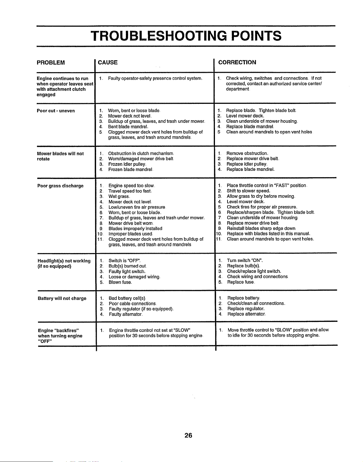
i i i i ii lILly iiiinll[lUllllll
TROUBLESHOOTING POINTS
PROBLEM
Engine continues to run
when operator leaves seat
with attachment clutch
engaged
Poor cut - uneven
Mower blades will not
rotate
i/
Poor grass discharge
Headlight(s) not working
(if so equipped)
Battery witl not charge
Engine "backfires"
when turning engine
"OFF"
CAUSE
1, Faulty operator-safety presence control system.,
1,, Worn, bent or loose blade,
2. Mower deck not level.
3,, Buildup of grass, leaves, and trash under mower,
4, Bent blade mandrel
5 Clogged mower deck vent holes from buildup of
grass, leaves, and trash around mandrels.
CORRECTION
1. Check wiring, switches and connections.. If not
corrected, contact an authorized service canter/
department,
1. Replace blade. Tighten blade bolt.
2. Level mower deck.
3, Clean undersfdeof mower housing.
4. Replace blade mandrel,
5 Clean around mandrels to open vent holes
1, Obstructtonin clutch mechanism,
2, Worn/damaged mower drive belt.
3,, Frozen idler pulley.
4, Frozen blade mandrel
1. Engine speed too slow,
2, Travel speed too fast.
3, Wet grass.
4,, Mower deck not level.
5,, Lowtuneven tire air pressure,
6. Wom, bent or loose blade,,
7. Buildup of grass, leaves and trash under mower_
8, Mower drive belt worn
9, Blades improperly Installed
10 Improper blades used,
t 1, Clogged mower deck vent holes from buildup of
grass, leaves, and trash around mandrels
1., Switch is "OFF".
2, Bulb(s) bumedout
3. Faulty light switch.
4, Loose or damaged wiring.
5. Blown fuse.
I. Remove obstruction.,
2 Replace mower drive belt,.
3. Replace idler pulley.,
4. Replace blade mandrel
1, Place throttle control in "FAST" position,
2, Shift to slower speed.
3, Allow grass to dry before mowing.
4. Level mower deck.
5. Check tires for proper air pressure.
6, Replace/sharpen blade. Tighten blade belt,
7. Clean underside of mower housfng,
8. Replace mower drive belt.
9, Reinstall blades sharp edge down
t0., Replace with blades listed in this manual
1, Clean around mandrels to open vent holes,.
1., Turn switch "ON".,
2. Replace bulb(s).,
3. Check/replace light switch.
4, Check wiring and connections,
& Replace fuse,
1,, Bad battery cell(s).
2o Poor cable connections
3 Faulty regulator (if so equipped),,
4. Faulty alternator.
1, Replace battery,
2, Check/clean all connections.,
3, Reptace regulator.,
4, Replace alternator.
1. Move throttle control to "SLOW _ position and allow
to idle for 30 seconds before stopping engine.
Engine throttle control not set at "SLOW"
position for 30 seconds before stepping engine
26
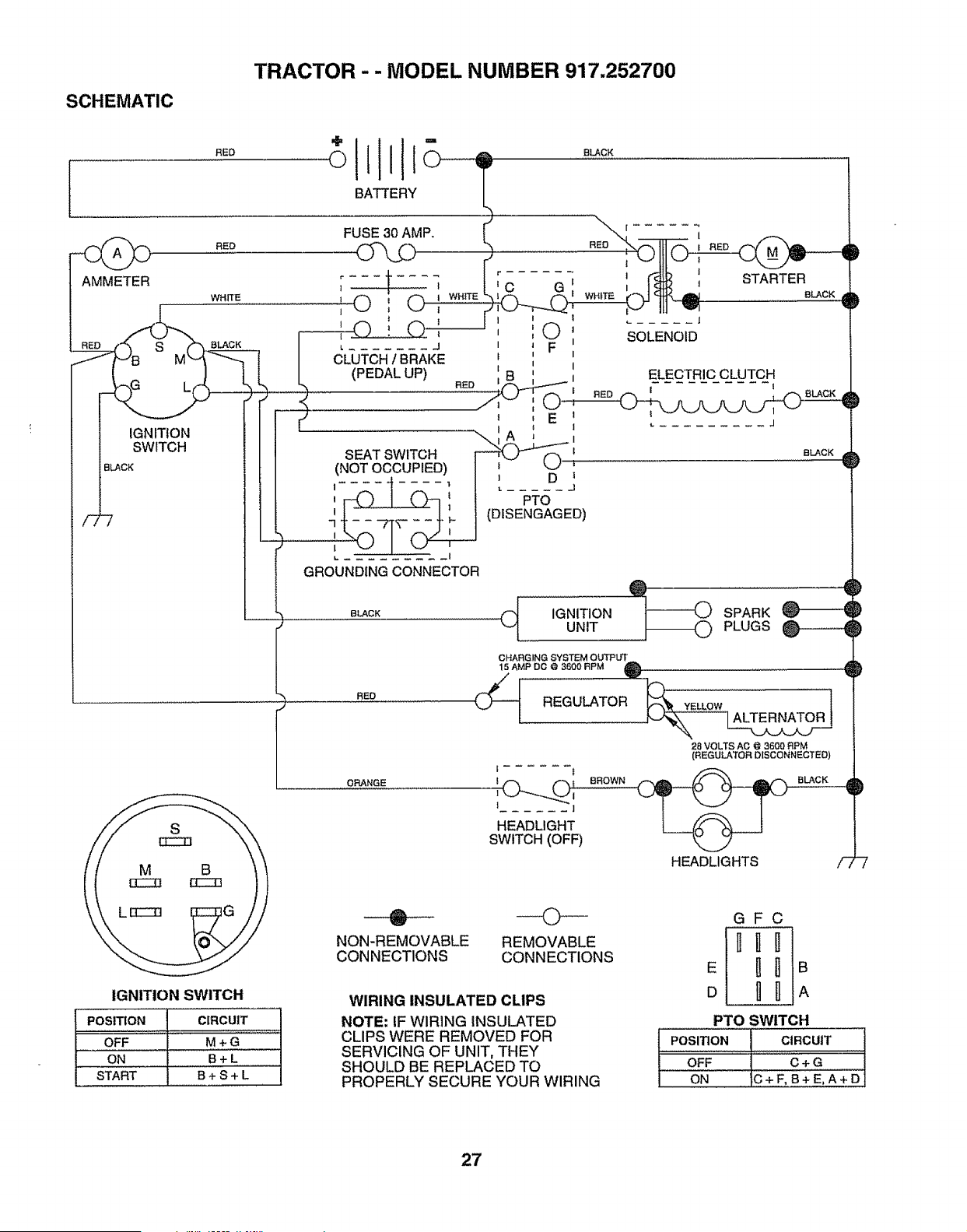
SCHEMATIC
TRACTOR - - MODEL NUMBER 917.252700
RED
l ORANGE
S
NON-REMOVABLE
CONNECTIONS
ELECTRIC CLUTCH
"ED_ A AAA_
J
BLACK
@
_ SPARK
,, PLUGS
CHARGING SYSTEM OUTPUT
15 AMP DO @ 3600 RPM Q
(_ REGULATOR
i C..,_..,.__ O, BROWN
t 1
HEADLIGHT
SWITCH (OFF)
----O--
REMOVABLE
CONNECTIONS
D
D
IlL
V
IGNITION SWITCH
POSITION CIRCUIT
OFF M + G
ON B+ L
START B + S + L
WIRING INSULATED CLIPS
NOTE: IF WIRING INSULATED
CLIPS WERE REMOVED FOR
SERVICING OF UNIT, THEY
SHOULD BE REPLACED TO
PROPERLY SECURE YOUR WIRING
:28 VOLTS AO @ 3600 RPM
(REGULATOR DISCONNECTED)
HEADLIGHTS /- -Z
GFC
E _ _ B
D _ _ A
PTO SWITCH
POSITION
OFF
ON
CIRCUIT
C+G
C+F,B+E,A+D
27
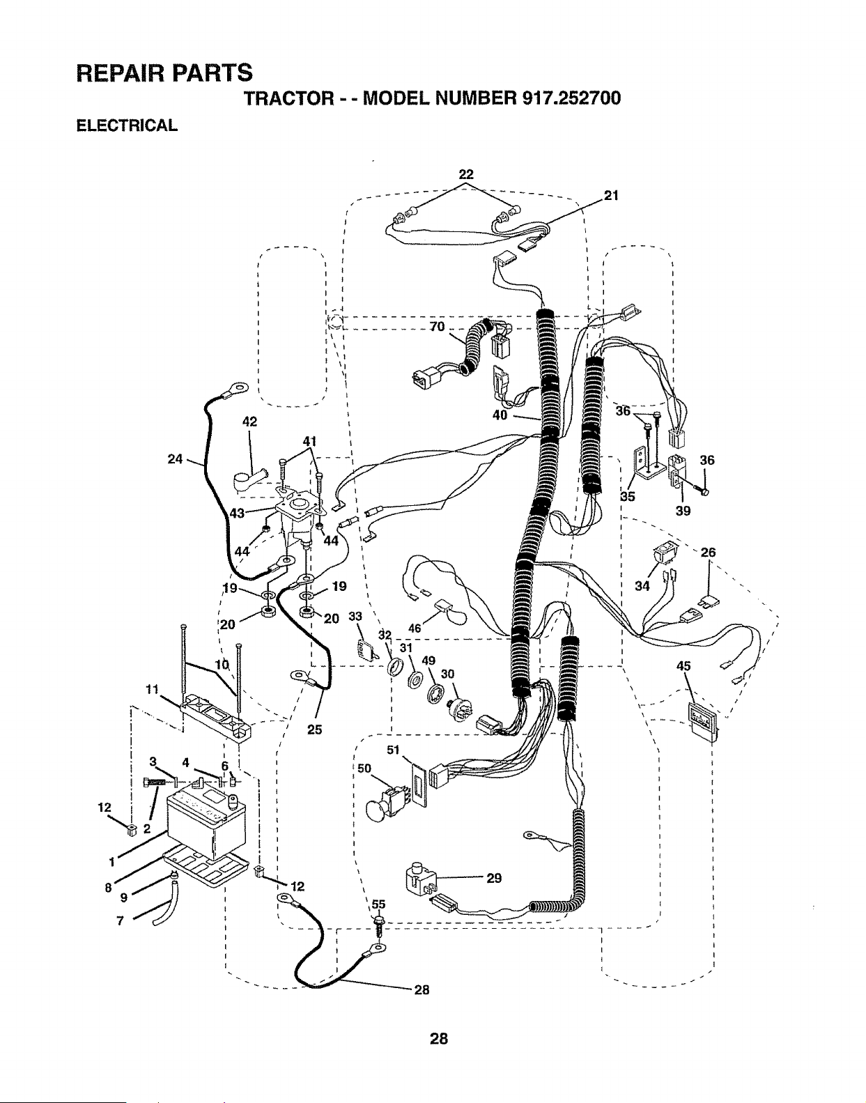
REPAIR PARTS
TRACTOR -- MODEL NUMBER 917.252700
ELECTRICAL
42
4O
36
25
29
39
! _ 26
i
28
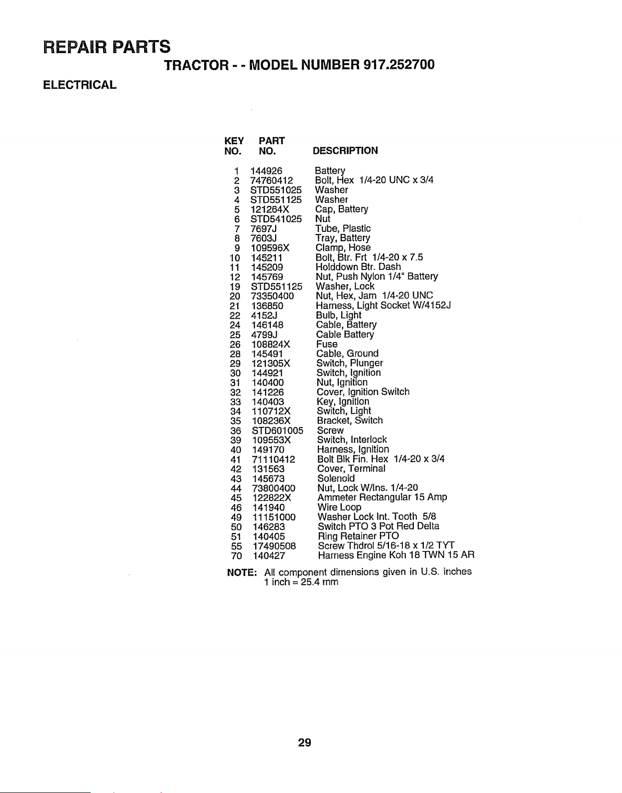
REPAIR PARTS
TRACTOR -- MODEL NUMBER 917.252700
ELECTRICAL
KEY PART
NO. NO. DESCRIPTION
1 144926 Battery
2 74760412 Bolt, Hex 1/4-20 UNC x 3/4
3 STD551025 Washer
4 STD551125 Washer
5 121264X Cap, Battery
6 STD541025 Nut
7 7697J Tube, Plastic
8 7603J Tray, Battery
9 109596X Clamp, Hose
10 145211 Bolt, Btr_ Frt 1/4-20 x 7_5
11 145209 Hotddown Btr. Dash
12 145769 Nut, Push Nylon t/4" Battery
19 STD551125 Washer, Lock
20 73350400 Nut, Hex, Jam 1/4-20 UNC
21 136850 Harness, Light SocketW/4152J
22 4152J Bulb, Light
24 146148 Cable, Battery
25 4799J Cable Battery
26 108824X Fuse
28 14549t Cable, Ground
29 121305X Switch, Plunger
30 144921 Switch, Ignition
31 140400 Nut, Ignition
32 141226 Cover, Ignition Switch
33 140403 Key, Ignition
34 110712X Switch, Light
35 108236X Bracket, Switch
36 STD601005 Screw
39 109553X Switch, lnterSock
40 i49170 Harness, Ignition
41 711 t0412 Bolt BIk Fin_Hex 1/4-20 x 3/4
42 131563 Cover, Terminal
43 145673 Solenoid
44 73800400 Nut, Lock W/ins. 1/4-20
45 122822X Ammeter' Rectangular t5 Amp
46 141940 Wire Loop
49 11151000 Washer' Lock lnt.,Tooth 5/8
50 146283 Switch PTO 3 Pot Red Delta
51 140405 Ring Retainer'PTO
55 17490508 Screw Thdrol 5/16-18 x 1/2 TYT
70 140427 Harness Engine Koh 18 TWN 15 AR
NOTE; Ali component dimensions given in UoS_inches
1 inch = 25..4 mm
29
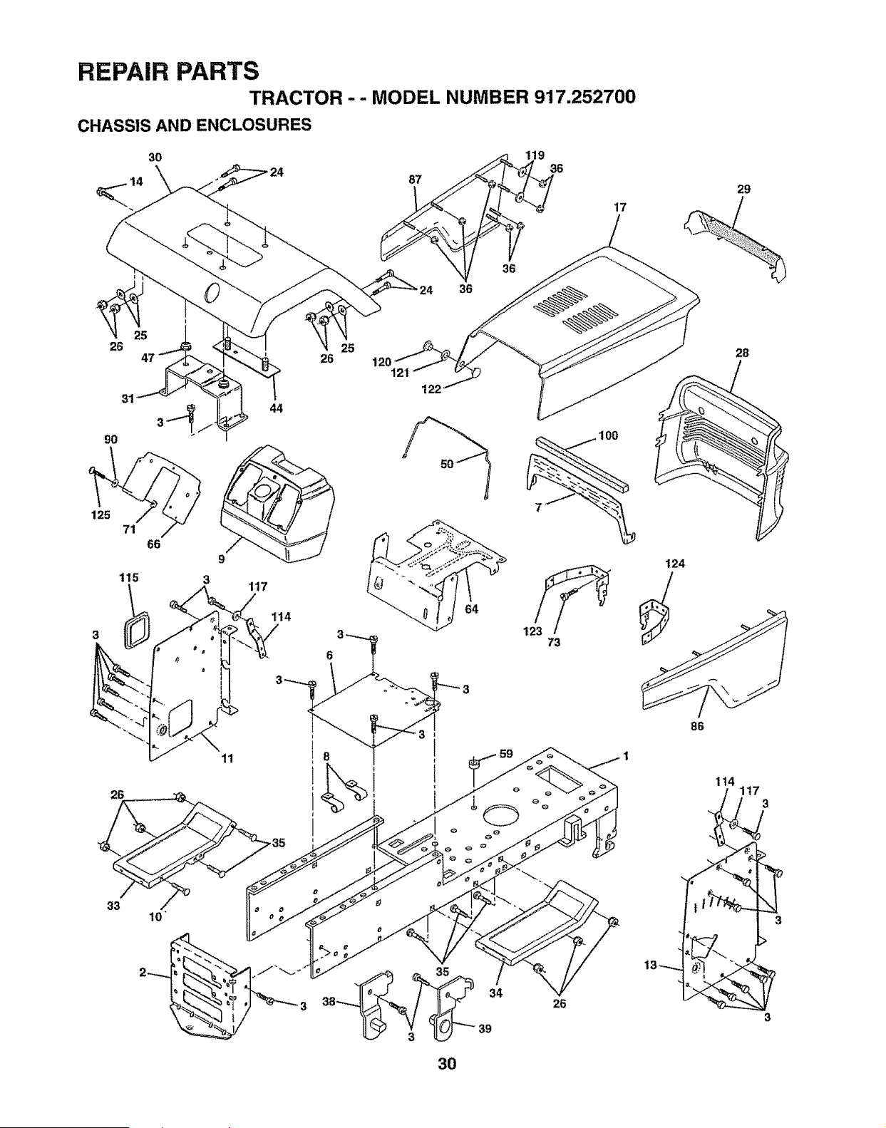
REPAIR PARTS
TRACTOR - - MODEL NUMBER 917.252700
CHASSIS AND ENCLOSURES
3O
119 36
87
36
17
29
26 25
26
31
44
120
121
122
26
33
39
73
26
28
124
86
114
3
3
30
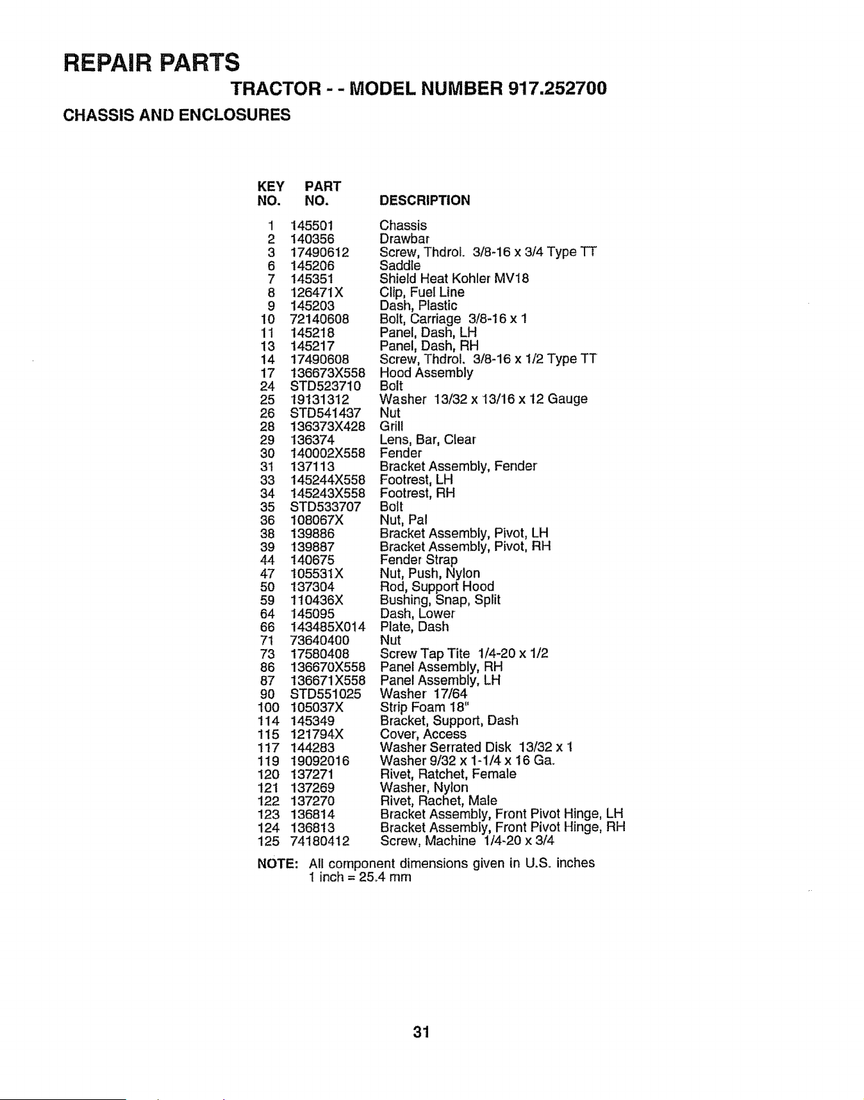
REPAIR PARTS
TRACTOR -- MODEL NUMBER 917.252700
CHASSIS AND ENCLOSURES
KEY PART
NO. NO. DESCRIPTION
1 145501 Chassis
2 140356 Drawbar
3 t7490612 Screw, Thdrol. 3/8-16 x 3/4 Type TT
6 145206 Saddle
7 145351 Shield Heat Kohler MV18
8 126471X Clip, FuelLine
9 145203 Dash, Plastic
10 72140608 Bolt, Carriage 3/8-16 x 1
11 145218 Panel, Dash, LH
13 145217 Panel, Dash, RH
14 17490608 Screw, Thdrol. 3/8-16 x I/2 Type TT
17 136673X558 Hood Assembly
24 STD5237i0 Bolt
25 19131312 Washer 13/32 x 13/16 x 12 Gauge
26 STD541437 Nut
28 136373X428 Grill
29 136374 Lens, Bar, Clear
30 140002X558 Fender
3t 137113 Bracket Assembly, Fender
33 145244X558 Footrest, LH
34 t45243X558 Footrest, RH
35 STD533707 Bolt
36 108067X Nut, Pal
38 139886 Bracket Assembly, Pivot, LH
39 139887 Bracket Assembly, Pivot, RH
44 140675 Fender Strap
47 105531X Nut, Push, Nylon
50 137304 Rod, Support Hood
59 110436X Bushing, Snap, Split
64 145095 Dash, Lower
66 143485X014 Plate, Dash
71 73640400 Nut
73 17580408 Screw Tap Tite 1/4-20 x 1/2
86 136670X558 Panel Assembly, RH
87 136671X558 Panel Assembly, LH
90 8TD551025 Washer 17/64
100 105037X Strip Foam 18"
114 145349 Bracket, Support, Dash
115 121794X Cover, Access
1!7 144283 Washer Serrated Disk 13/32 x !
119 19092016 Washer 9/32 x 1-1/4 x 16 Ga_
120 137271 Rivet, Ratchet, Female
12t 137269 Washer, Nylon
122 137270 Rivet, Rachet, Male
123 136814 Bracket Assembly, Front Pivot Hinge, LH
124 136813 Bracket Assembly, Front Pivot Hinge, RH
125 74180412 Screw, Machine 1/4-20x3/4
NOTE:
All component dimensions given in U.S. inches
1 inch = 25°4 mm
31
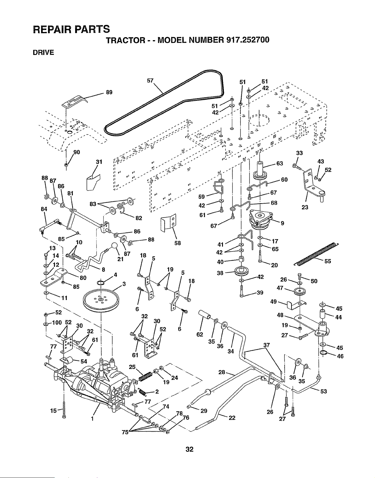
REPAIR PARTS
TRACTOR -- MODEL NUMBER 917.252700
DRIVE
57
51 51
8
4
• 1 85_ 3
i 1
77
1
19
5
18
6
62
35
36
34
i
26
27
32
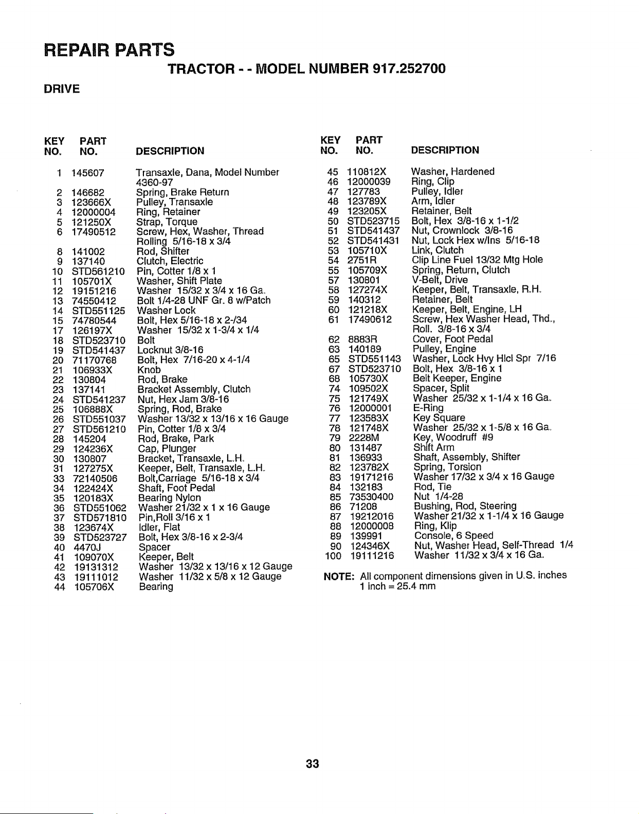
REPAIR PARTS
TRACTOR-- MODEL NUMBER 917.252700
DRIVE
KEY PART KEY PART
NO= NO. DESCRIPTION NO. NO. DESCRIPTION
1 145607 Transaxle, Dana, Model Number 45 110812X
4360-97 46 12000039
2 146682 Spring, Brake Return 47 127783
3 123666X Pulley, Transaxle 48 123789X
4 12000004 Ring, Retainer 49 !23205X
5 t21250X Strap, Torque 50 STD523715
6 17490512 Screw, Hex, Washer, Thread 51 STD54t437
Roiling 5/I6-18 x 3/4 52 STD541431
8 141002 Rod, Shifter 53 105710X
9 137140 Clutch, Electric 54 2751R
10 STD561210 Pin, Cotter 1/8 x t 55 105709X
11 105701X Washer', Shift Plate 57 130801
12 19151216 Washer 15/32x3i4x16Ga.. 58 127274X
t3 74550412 Bolt t/4-28 UNF Gro8 w!Patch 59 140312
14 STD551125 WasherLock 60 121218X
15 74780544 Bolt, Hex 5/t6_18 x 2-/34 61 17490612
17 126197X Washer 15/32xl-3i4xli4
18 STD523710 Bolt 62 8883R
19 STD541437 Locknut3/8-16 63 140189
20 71170768 Bolt, Hex 7/16-20 x4-t/4 65 STD551t43
21 106933X Knob 67 STD523710
22 130804 Rod, Brake 68 105730X
23 137141 Bracket Assembly, Clutch 74 109502X
24 STD541237 Nut, Hex Jam 3/8-16 75 121749X
25 106888X Spring, Rod, Brake 76 12000001
26 STD551037 Washer'13/32 x 13/16 x 16 Gauge 77 123583X
27 STD561210 Pin, Cotter' 1/8 x3/4 78 121748X
28 145204 Rod, Brake, Park 79 2228M
29 124236X Cap, Plunger 80 131487
30 130807 Bracket, Transaxle, LH_ 81 136933
31 127275X Keeper, Belt, Transaxle, L.H. 82 I23782X
33 72140506 Bolt,Carriage 5/16-18 x3/4 83 19171216
34 122424X Shaft, Foot Pedal 84 132183
35 120183X Bearing Nylon 85 73530400
36 STD551062 Washer21!32x1 x16Gauge 86 71208
37 STD571810 Pin,Roll3/16 x I 87 19212016
38 123674X Idler, Flat 88 12000008
39 STD523727 Bolt, Hex 3/8-16 x 2-3/4 89 139991
40 4470J Spacer 90 t24346X
41 109070X Keeper, Belt 100 19111216
42 19131312 Washer 13/32 x13/16 x12 Gauge
43 19111012 Washer 11/32 x 5/8 x12 Gauge
44 105706X Bearing
Washer, Hardened
Ring, Clip
Pulley, Idler
Arm, Idler
Retainer, Belt
Bolt, Hex 3/8-16 x 1-1/2
Nut, Crownlock 3/8-16
Nut, Lock Hex w/Ins 5/16-18
Link, Clutch
Clip Line Fuel 13/32 Mtg Hole
Spring, Return, Clutch
V-Belt, Drive
Keeper, Belt, Transaxle, RoH_
Retainer', Belt
Keeper, Belt, Engine, LH
Screw, Hex Washer Head, Thd..,
Roll. 3/8-16 x 3/4
Cover', Foot Pedal
Pulley, Engine
Washer, Lock Hvy Hlcl Spr 7/16
Bolt, Hex 3/8-16 x 1
Belt Keeper, Engine
Spacer, Split
Washer 25/32 x 1-1/4 x 16 Gao
E-Ring
Key Square
Washer' 25/32 x 1-5/8 x 16 Gao
Key, Woodruff #9
Shift Arm
Shaft, Assembly, Shifter
Spring, Torsion
Washer t7/32 x 3/4 x 16 Gauge
Rod, Tie
Nut 1/4-28
Bushing, Rod, Steering
Washer 21/32 x 1-1/4 x 16 Gauge
Ring, Klip
Console, 6 Speed
Nut, Washer Head, Self-Thread 1/4
Washer 11/32 x 3/4 x 16 Gao
NOTE: Ali component dimensions given in U.Soinches
1 inch = 25.4 mm
33
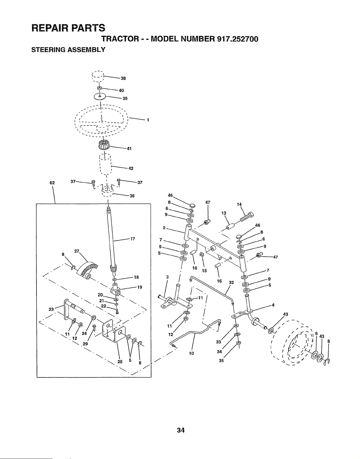
REPAIR PARTS
TRACTOR - - MODEL NUMBER 9'17.252700
STEERING ASSEMBLY
62
...... _ _ .... J t
I €
t
./," _
<t"
46,
47 14
\
16 32
33
34
35
46
43
34
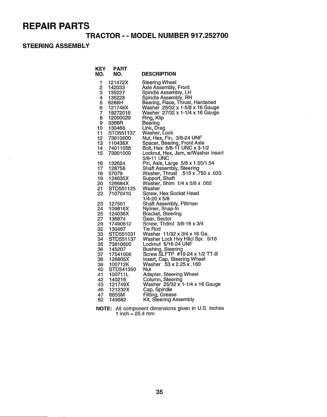
REPAIR PARTS
TRACTOR - - MODEL NUMBER 917.252700
STEERING ASSEMBLY
KEY PART
NO. NO. DESCRIPTION
1 121472X
2 142033
3 135227
4 135228
5 6266H
6 121748X
7 19272016
8 12000029
9 3366R
10 130468
11 STD551137
12 73610600
13 110438X
14 74011056
15 739O1OOO
16 132624
17 128758
18 57079
19 124035X
20 126684X
2t STD551125
22 71070410
23 127501
24 109816X
25 124036X
27 136874
29 17490612
32 130467
33 STD551031
34 STD551137
35 73810500
36 145207
37 17541008
38 126805X
39 100712K
40 STD541350
41 100711L
42 140216
43 121749X
46 121232X
47 6855M
62 149682
NOTE:
Steering Wheel
Axle Assembly, Front
Spindle Assembly, LH
Spindle Assembly, RH
Bearing, Race, Thrust, Hardened
Washer 25/32 x 1-5/8 x 16 Gauge
Washer 27/32 x 1-1/4 x 16 Gauge
Ring, Klip
Bearing
Link, Drag
Washer, Lock
Nut, Hex, Fin, 3/8-24 UNF
Spacer, Bearing, Front Axle
Bolt, Hex 5/8-1 t UNC x 3-1/2
Locknut, Hex, Jam, w/Washer Insert
5/8-11 UNC
Pin, Axte, Large 5/8 x 1o55/1.54
Shaft Assembly, Steering
Washer', Thrust .515 x .750 x .033
Support, Shaft
Washer, Shim 1/4 x 5/8 x .062
Washer
Screw, Hex Socket Head
1/4-20 x 5/8
Shaft Assembly, Pittman
Nyliner, Snap-ln
Bracket, Steering
Gear, Sector
Screw, Thdrol 3/8-16 x 3/4
Tie Rod
Washer 11/32 x 3/4 x 16 Ga.
Washer Lock Hvy Hllcl Spr. 5/t6
Locknut 5/16-24 UNF
Bushing, Steering
Screw SLFTP #10-24 x 1/2 TT-B
Insert, Cap, Steering Wheel
Washer _53x 2_25x .160
Nut
Adapter, Steering Wheel
Column, Steering
Washer 25/32 x 1-1/4 x 16 Gauge
Cap, Spindle
Fitting, Grease
Kit, Steering Assembly
All component dimensions given in U.S.. inches
1 inch = 25.4 mm
35
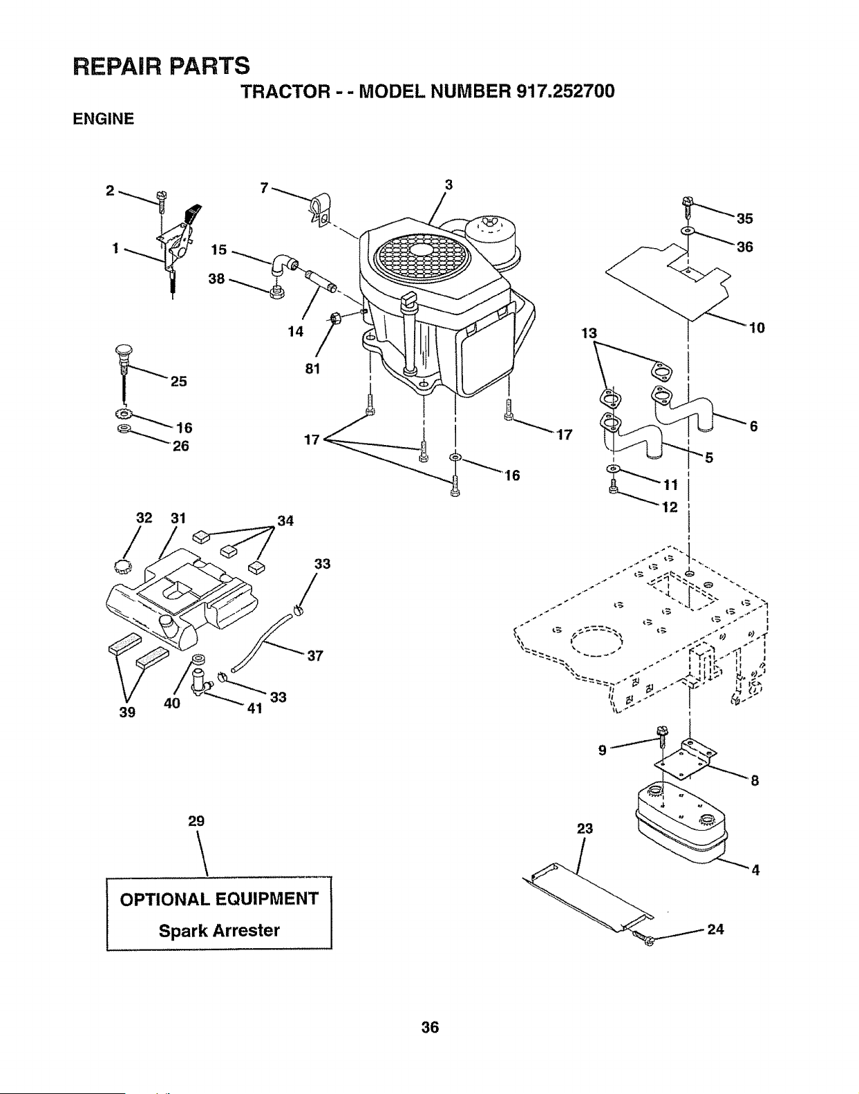
REPAIR
ENGINE
PARTS
TRACTOR -- MODEL NUMBER 917,252700
2
1_ 15
38
32 31
© Q
39
14
34
3
33
81
I
17 ! 17
33
/
37
ti
Jt
29
\
OPTIONAL EQUIPMENT
Spark Arrester
9
23
8
4
36
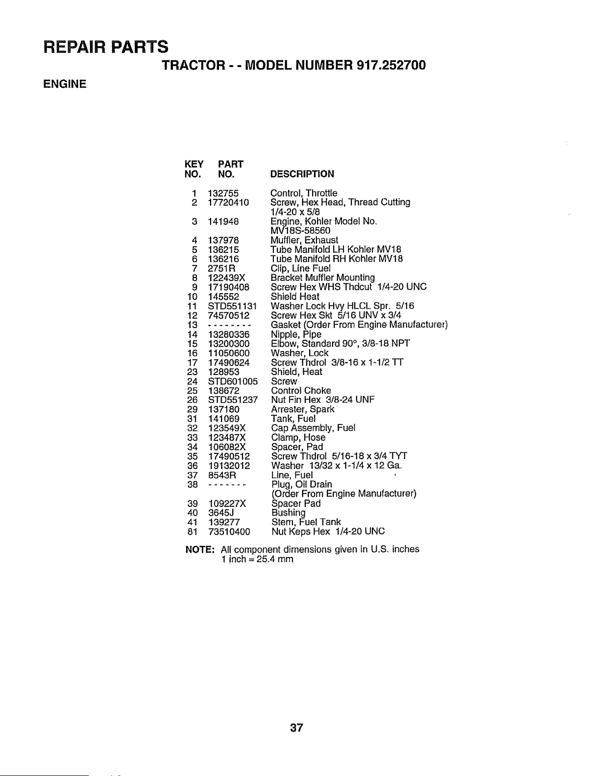
REPAIR
ENGINE
PARTS
TRACTOR -- MODEL NUMBER 917.252700
KEY PART
NO. NOo DESCRIPTION
1
2
132755
17720410
141948
4 137978
5 136215
6 136216
7 2751R
8 122439X
9 17190408
10 145552
11 STD551131
12 74570512
13 ........
14 13280336
15 13200300
16 11050600
17 17490624
23 128953
24 STD601005
25 138672
26 STD551237
29 137180
31 141069
32 123549X
33 123487X
34 106082X
35 17490512
36 19132012
37 8543R
38 .......
39 109227X
4O 3645J
41 139277
8t 73510400
Control, Throttle
Screw, Hex Head, Thread Cutting
1/4-20 x 5/8
Engine, Kohler Model No_
MV18S-58560
Muffler, Exhaust
Tube Manifold LH Kohler MV18
Tube Manifold RH Kohler MV18
Clip, Line Fuel
Bracket Muffler Mounting
Screw Hex WHS Thdcut 1/4-20 UNC
Shield Heat
Washer Lock Hvy HLCL Spr. 5/16
Screw Hex Skt 5/16 UNV x 3/4
Gasket (Order From Engine Manufacturer)
Nipple, Pipe
Elbow, Standard 90°, 3/8-18 NPT
Washer, Lock
Screw Thdrol 3/8-16 x 1_112TT
Shield, Heat
Screw
Control Choke
Nut Fin Hex 3/8-24 UNF
Arrester, Spark
Tank, Fuel
Cap Assembly, Fuel
Clamp, Hose
Spacer, Pad
Screw Thdrot 5/16-18 x 3/4 TYT
Washer 13/32 x 1-1/4 x 12 Ga.
Line, Fuel
Plug, OiI Drain
(Order From Engine Manufacturer)
Spacer Pad
Bushing
Stem, Fuel Tank
Nut Keps Hex 1/4-20 UNC
NOTE: All component dimensions given in UoSoinches
1 inch = 2&4 mm
37
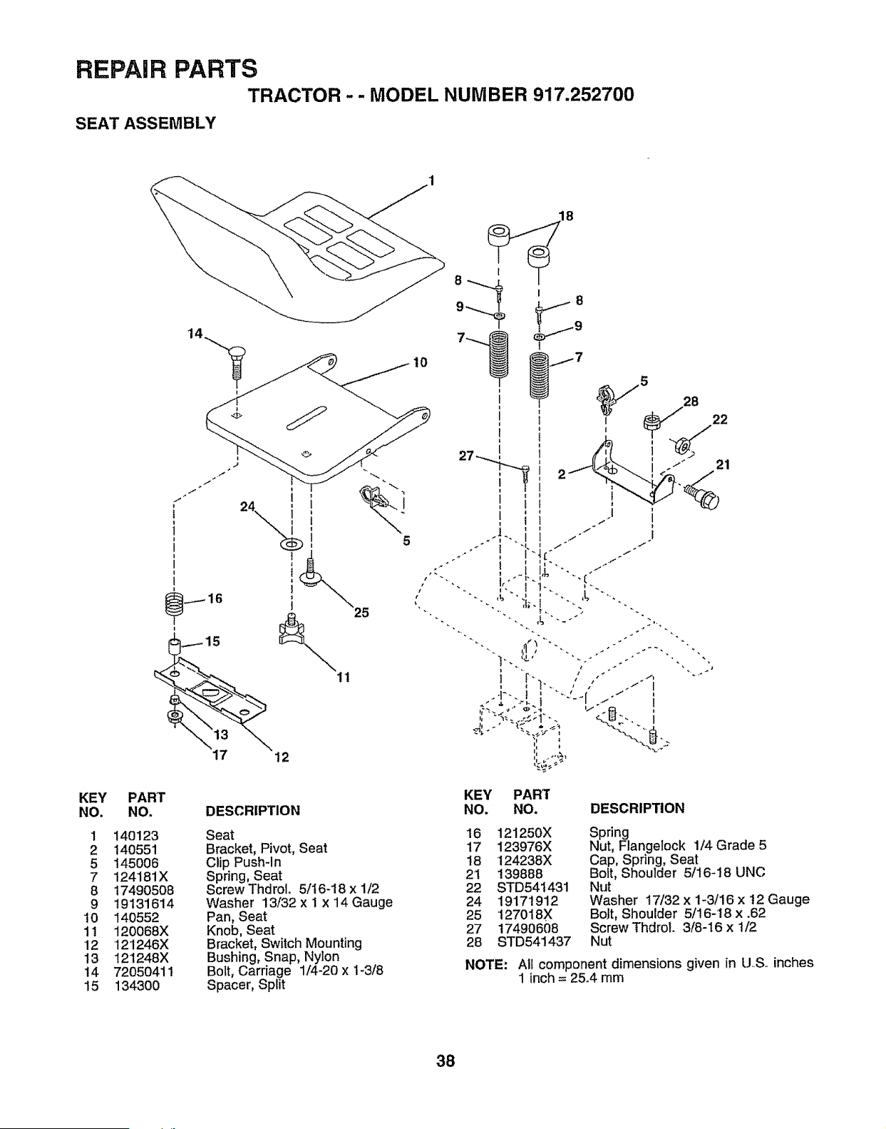
REPAIR PARTS
TRACTOR -- MODEL NUMBER 917.252700
SEAT ASSEMBLY
KEY PART
NO. NO.
1 140123
2 140551
5 145O06
7 124181X
8 17490508
9 19131614
10 140552
1t 120068X
12 121246X
13 121248X
14 72050411
15 134300
15
t
t
i
i
11
12
DESCRIPTION
Seat
Bracket, Pivot, Seat
Clip Push-In
Spring, Seat
Screw Thdrol. 5/I6-18 x 1/2
Washer 13/32 x 1 x 14 Gauge
Pan, Seat
Knob, Seat
Bracket, Switch Mounting
Bushing, Snap, Nylon
Bolt, Carriage 1/4-20 x 1-3/8
Spacer, Split
10
5 28
i
" 21
KEY PART
NO. NO. DESCRIPTION
16 121250X Spring
17 123976X Nut, Flangelock 1/4Grade 5
18 124238X Cap, Spring, Seat
21 139888 Bolt> Shoulder 5/16-18 UNC
22 STD54t431 Nut
24 19171912 Washer 17/32 x I-3/16 x 12 Gauge
25 t27018X BoJt, Shoulder 5/16-18 x .62
27 17490608 Screw ThdroL 3/8-16 x t/2
28 STD541437 Nut
NOTE: All component dimensions given in U.S. inches
1 inch = 25.4 mm
38
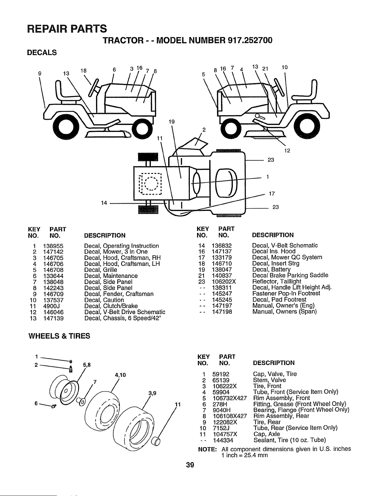
REPAIR
DECALS
9
PARTS
TRACTOR - - MODEL NUMBER 917.252700
13
18 6 3
14
7 8
11
19
8
5
\
7 4 21 10
23
1
17
23
12
KEY PART
NO. NO.
1 138955
2 147142
3 146705
4 146706
5 146708
6 133644
7 138048
8 142243
9 146709
10 137537
11 4900J
12 146046
13 147139
DESCRIPTION
Decat
Decal
Decal
Decal
Decal
Decal
Decal
Decal
Decal
Decal
Decal
Decal
Decal
Operating Instruction
Mower, 3 In One
Hood, Craftsman, RH
Hood, Craftsman, LH
Grilie
Maintenance
Side Panel
Side Panel
Fender, Craftsman
Caution
Clutch/Brake
V-Belt Drive Schematic
Chassis, 6 Speed/42"
KEY PART
NO, NO.
14 136832
16 147137
17 133179
18 146710
19 138047
21 140837
23 106202X
-- 138311
-- 145247
.- 145245
-- 147197
-- 147198
DESCRIPTION
Decal, V-Belt Schematic
Decal Ins Hood
Decal, Mower QC System
Decal, Insert Strg
Decal, Battery
Decal Brake Parking Saddle
Reflector, Taillight
Decal, Handle Lift Height Adj.
Fastener' Pop-in Footrest
Decal, Pad Footrest
Manual, Owner's (Eng)
Manual, Owners (Span)
WHEELS & TIRES
5,8
4,10
11
39
KEY PART
NO. NO. DESCRIPTION
1
2
3
4
5
6
7
8
9
10
11
59192
65139
106222X
59904
106732X427
278H
9040H
106108X427
122082X
7152J
104757X
144334
NOTE:
Cap, Valve, Tire
Stern, Valve
Tire, Front
Tube, Front (Service Item Only)
Rim Assembly, Front
Fitting, Grease (Front Wheel Only)
Bearing, Flange (Front Wheel Only)
Rim Assembly, Rear
Tire, Rear'
Tube, Rear (Service Item Only)
Cap, Axle
Sealant, Tire (10 oz. Tube)
All component dimensions given in U.,S, inches
1 inch = 25_4 mm
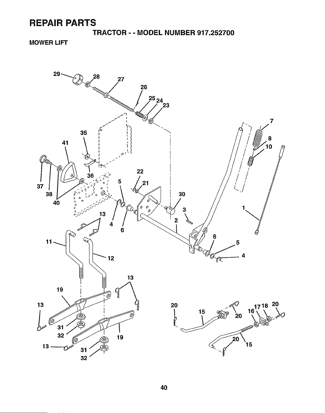
REPAIR PARTS
TRACTOR -- MODEL NUMBER 917.252700
MOWER LIFT
27
26
37
41
35
4
12
19
5
6
13
22
21
23
30
3
6
7
8
5
4
2O
4O
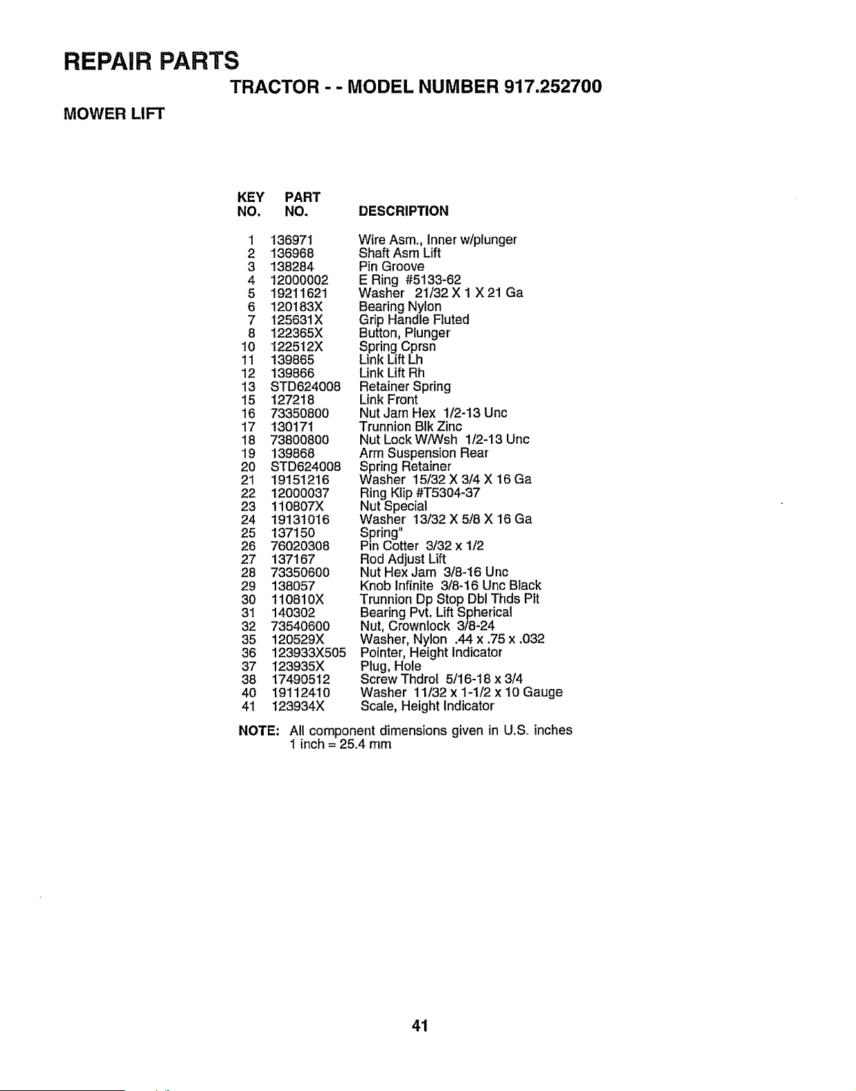
REPAIR PARTS
TRACTOR - - MODEL NUMBER 917.252700
MOWER LIFT
KEY PART
NO. NO. DESCRIPTION
1 136971
2 136968
3 138284
4 12000002
5 19211621
6 120183X
7 125631X
8 122365X
10 I22512X
11 139865
12 139866
13 STD624008
15 127218
16 7335O8OO
17 130171
18 73800800
19 139868
2O STD624008
21 19151216
22 12000037
23 110807X
24 19131016
25 13715O
26 76020308
27 137167
28 73350600
29 138O57
3O t10810X
31 14O3O2
32 73540600
35 120529X
36 123933X505
37 123935X
38 17490512
40 19112410
41 t23934X
Wire Asm., Inner w/plunger
Shaft Asm Lift
Pin Groove
E Ring #5133-62
Washer 21/32 X 1 X 21 Ga
Bearing Nylon
Grip Handle Fluted
Button, Plunger
Spring Cprsn
Link Lift Lh
Link Lift Rh
Retainer Spring
Link Front
Nut Jam Hex t/2-13 Unc
Trunnion Bik Zinc
Nut Lock W/Wsh 1/2-13 Unc
Arm Suspension Rear
Spring Retainer
Washer 15/32 X 3/4 X 16 Ga
Ring Klip #T5304-37
Nut Special
Washer' !3/32 X 5/8 X 16 Ga
Spring"
Pin Cotter 3/32 x t/2
Rod Adjust Lift
Nut Hex Jam 3/8-16 Unc
Knob Infinite 3/8-16 Unc Black
Trunnion Dp Stop Dbl Thds Pit
Bearing Pvt. LiftSpherical
Nut, Crownlock 3/8-24
Washer, Nylon .44 x .75 x .032
Pointer, Height Indicator
Plug, Hole
Screw Thdrof 5/16-18 x 3/4
Washer 11/32 x 1-1/2 x 10 Gauge
Scale, Height Indicator'
NOTE: All component dimensions given in U_S_inches
t inch = 25A mm
41
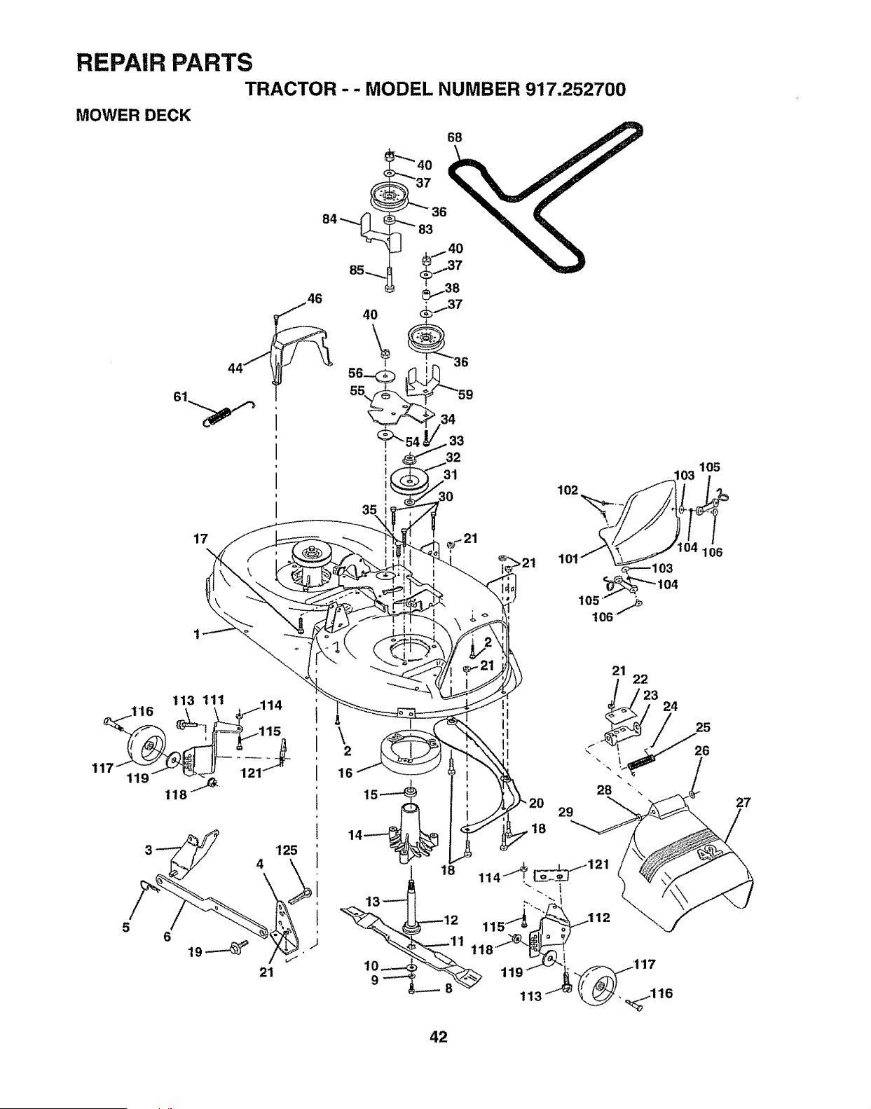
REPAIR PARTS
TRACTOR -- MODEL NUMBER 917.252700
MOWER DECK
68
102
105
17
105 _" ,_
t06"
106
:I'16 113 11_ _ 114
\
2
16
18
29
18
21
28
22
23
24
25
26
27
42
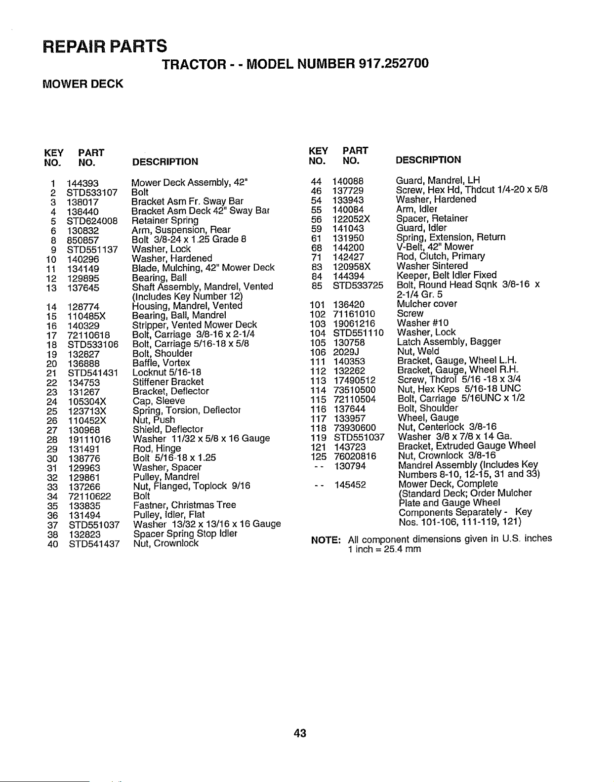
REPAIR PARTS
TRACTOR - - MODEL NUMBER 917.252700
MOWER DECK
KEY PART KEY PART
NO. NO. DESCRIPTION NO. NO. DESCRIPTION
1 144393 Mower Deck Assembly, 42" 44 140088
2 STD533107 Bolt 46 137729
3 138017 Bracket Asm Fr. Swa.y Bar' 54 133943
4 138440 Bracket Asrn Deck 42 Sway Bar 55 140084
5 STD624008 Retainer Spring 56 122052X
6 130832 Arm, Suspension, Rear 59 141043
8 850857 Bolt 3/8-24x 1.25 Grade 8 61 131950
9 STD551137 Washer, Lock 68 144200
10 140296 Washer, Hardened 71 142427
11 134149 Blade, Mulching, 42" Mower Deck 83 120958X
12 129895 Bearing, Ball 84 144394
13 137645 Shaft Assembly, Mandrel, Vented 85 STD533725
(Includes Key Number 12)
14 128774 Housing, Mandrel, Vented 10t 136420
!5 i10485X Bearing, Ball, Mandrel 102 71161010
16 140329 Stripper, Vented Mower Deck 103 19061216
17 72110618 Bolt, Carriage 3/8-16 x2-1/4 104 STD551110
18 STD533106 Bolt, Carriage 5/I648x5/8 105 130758
19 132827 Bolt, Shoulder 106 2029J
20 136888 Baffle, Vortex 111 140353
2i STD541431 Locknut5/16-18 112 132262
22 134753 Stiffener' Bracket 113 17490512
23 131267 Bracket, Deflector !14 73510500
24 105304X Cap, Sleeve 115 72110504
25 123713X Spring, Torsion, Deflector 116 137644
26 110452X Nut, Push 117 133957
27 t30968 Shield, Deflector 118 73930600
28 19111016 Washer 11/32 x 5/8 x 16 Gauge 1i9 STD55t037
29 131491 Rod, Hinge 121 143723
30 138776 Bolt 5/16-18 x 1_25 125 76020816
31 129963 Washer', Spacer - - 130794
32 129861 Pulley, Mandrel
33 137266 Nut, Flanged, Toplock 9/t6 - - 145452
34 72110622 Bolt
35 133835 Fastner, Christmas Tree
36 131494 Pulley, Idler, Flat
37 STD551037 Washer' 13/32x 13/16 x 16 Gauge
38 132823 Spacer Spring Stop Idler
40 STD541437 Nut, Crownlock NOTE:
Guard, Mandrel, LH
Screw, Hex Hd, Thdcut 1/4-20 x 5/8
Washer, Hardened
Arm, Idler
Spacer, Retainer
Guard, ldler
Spring, Extension, Return
V-Belt, 42" Mower
Rod, Clutch, Primary
Washer' Sintered
Keeper, Belt Idler Fixed
BoIt, Round Head Sqnk 3/8-16 x
2-1/4 Gro 5
Mulcher cover
Screw
Washer #10
Washer, Lock
Latch Assembly, Bagger
Nut, Weld
Bracket, Gauge, Wheel L_H.
Bracket, Gauge, Wheel RoHo
Screw, Thdrol 5116 -t8 x 3/4
Nut, Hex Keps 5/16-18 UNC
Bolt, Carriage 5/16UNC x 1/2
Bolt, Shoulder
Wheel, Gauge
Nut, Centertock 3/8-16
Washer 3/8 x 7/8 x 14 Ga,.
Bracket, Extruded Gauge Wheel
Nut, Crowntock 3/8-16
Mandrel Assembly (Includes Key
Numbers 8-10, 12-t5, 31 and 33)
Mower Deck, Complete
(Standard Deck; Order Mulcher
Plate and Gauge Wheel
Components Separately - Key
Nos,.101-106, 111-119, 121)
All component dimensions given in U,S.. inches
1 inch = 25.4 mm
43
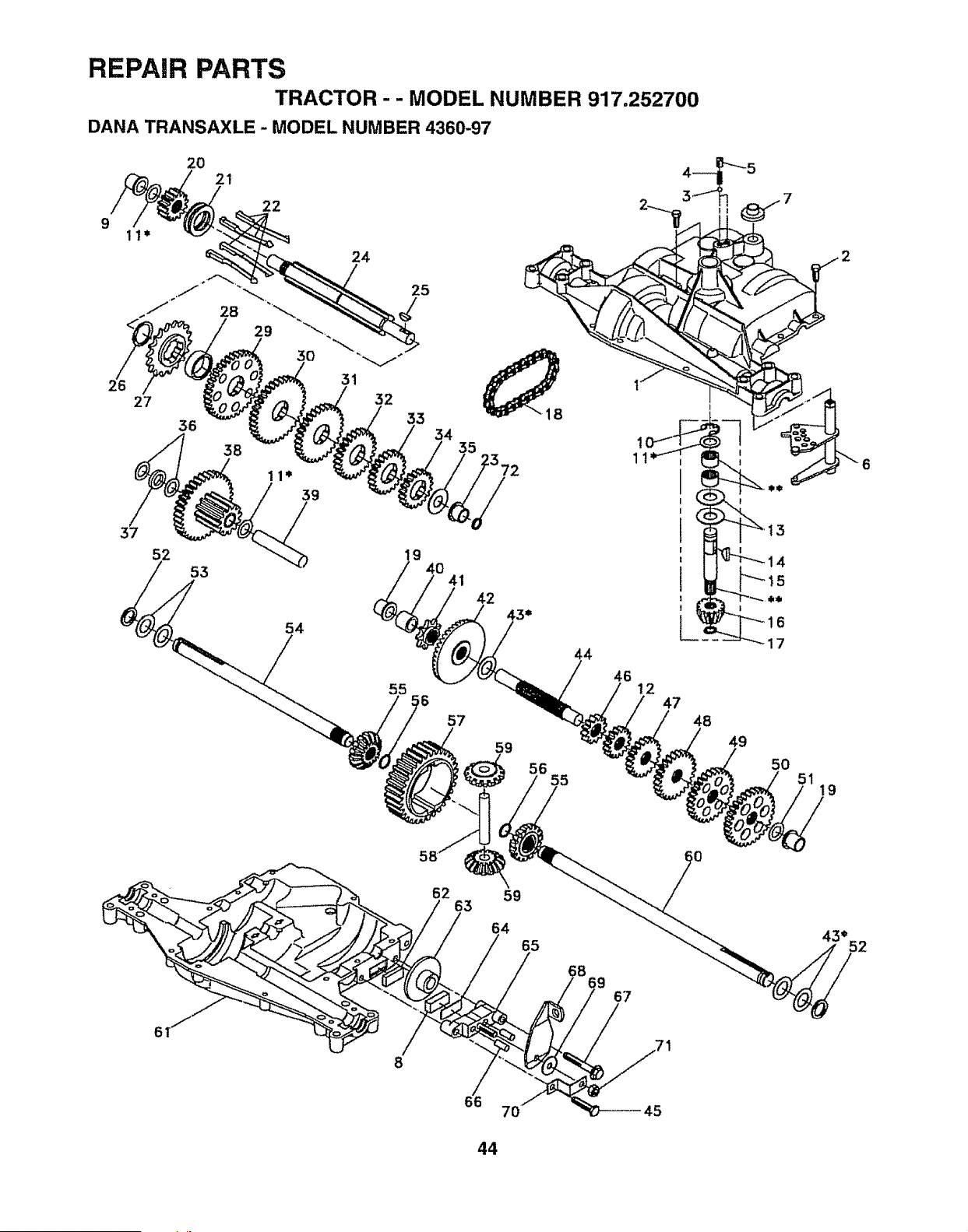
REPAIR PARTS
TRACTOR- - MODEL NUMBER 917.252700
DANA TRANSAXLE - MODEL NUMBER 4360-97
9
27
37
52
2O
56
2!
53
22
54
24
31
25
32
33
34
35
9
40
41
55
,6
57
4
46
12
47
59
56
55
!
48
49
15
50
19
62
63
59
65
68
67
43*
52
8
66
7O
44
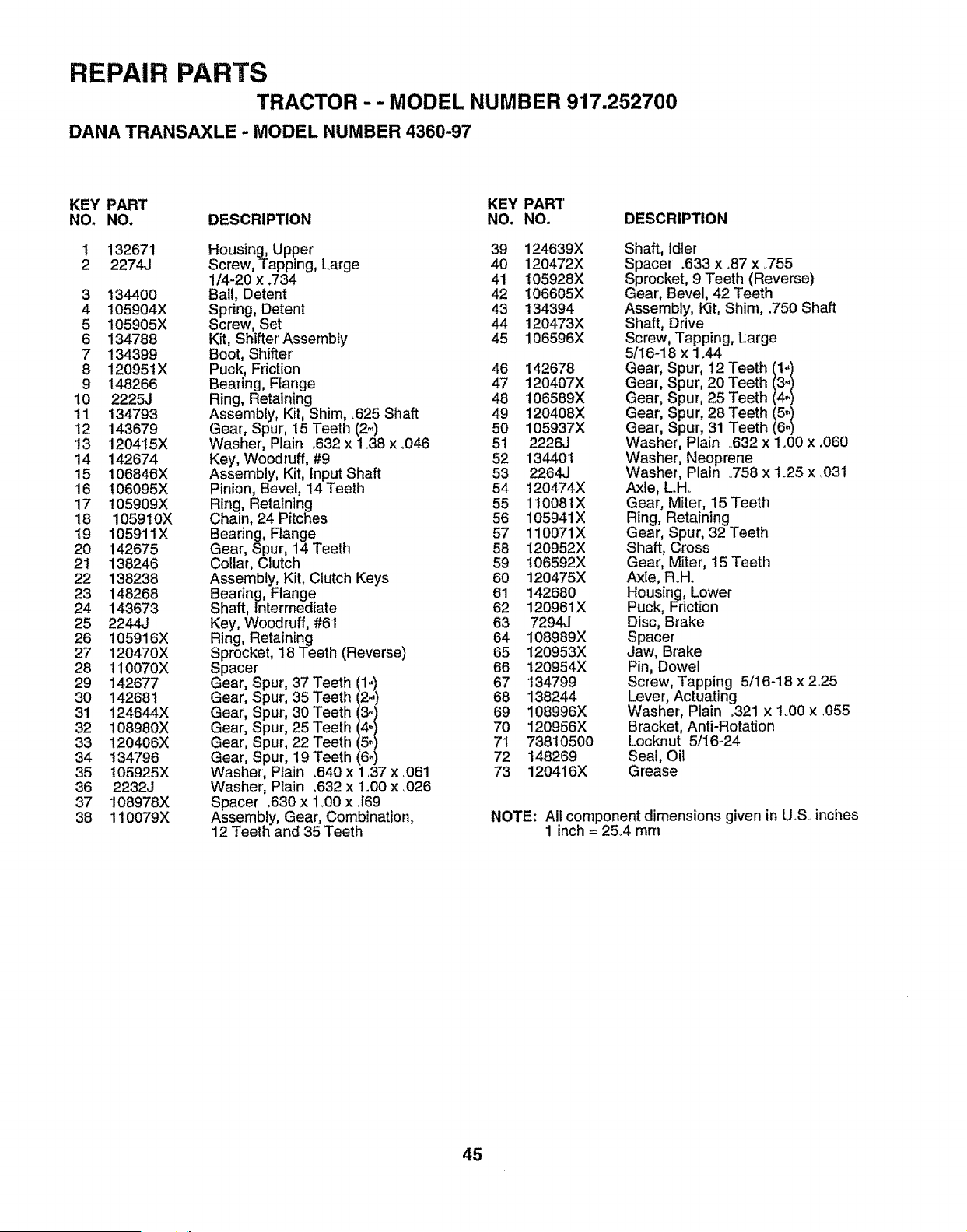
REPAIR PARTS
TRACTOR -- MODEL NUMBER 917.252700
DANA TRANSAXLE - MODEL NUMBER 4360-97
KEY PART KEY PART'
NO. NO. DESCRIPTION NO. NO. DESCRIPTION
1
2
132671
2274J
3 134400
4 105904X
5 105905X
6 134788
7 134399
8 120951X
9 148266
10 2225J
11 134793
12 143679
13 120415X
14 142674
15 106846X
16 106095X
17 105909X
18 105910X
19 105911X
20 142675
21 138246
22 138238
23 148268
24 143673
25 2244J
26 i05916X
27 120470X
28 110070X
29 142677
30 142681
31 124644X
32 108980X
33 120406X
34 134796
35 105925X
36 2232J
37 108978X
38 110079X
Housing, Upper
Screw, Tapping, Large
1/4-20 x .734
Ball, Detent
Spring, Detent
Screw, Set
Kit, Shifter Assembly
Boot, Shifter
Puck, Friction
Bearing, Range
Ring, Retaining
Assembly, Kit, Shim, .625 Shaft
Gear, Spur', 15 Teeth (2-)
Washer, Plain .632 x 1.38 x °046
Key, Woodruff, #9
Assembly, Kit, fnput Shaft
Pinion, Bevel, 14 Teeth
Ring, Retaining
Chain, 24 Pitches
Bearing, Flange
Gear, Spur, 14 Teeth
Collar, Clutch
Assembly, Kit, Clutch Keys
Bearing, Flange
Shaft, intermediate
Key, Woodruff, #61
Ring, Retaining
Sprocket, 18 Teeth (Reverse)
Spacer
Gear, S _ur, 37 Teeth t1:/
Gear, S _ur, 35 Teeth
Gear, S 3ur, 30 Teeth (3_)
Gear, S _ur, 25 Teeth/4:1
Gear, S 3ur, 22 Teeth
Gear, S 3ur, 19 Teeth (6-)
Washer Plain .640 x 1.37 x .061
Washer Plain .632 x 1.00 x .Q26
Spacer .630 x 1_00x .169
Assembly, Gear, Combination,
12 Teeth and 35 Teeth
39 124639X Shaft, Idler
40 120472X Spacer .633 x .87 x _755
41 !05928X Sprocket, 9 Teeth (Reverse)
42 106605X Gear, Bevel, 42 Teeth
43 134394 Assembly, Kit, Shim, .750 Shaft
44 120473X Shaft, Drive
45 106596X Screw, Tapping, Large
5/16-18 x 1.44
46 142678 Gear, Spur, 12 Teeth/1. }
47 120407X Gear, Spur, 20 Teeth 3.
48 106589X Gear, Spur, 25 Teeth 4.
49 120408X Gear, Spur, 28 Teeth _5-)
50 105937X Gear, Spur, 31 Teeth ()64
51 2226J Washer, Plain _632 x 1o00x ,060
52 134401 Washer, Neoprene
53 2264J Washer, Plain °758 x 1.25 x .,031
54 120474X Axle, Loll..
55 110081X Gear, Miter, 15 Teeth
56 105941X Ring, Retaining
57 110071X Gear, Spur, 32 Teeth
58 120952X Shaft, Cross
59 106592X Gear, Miter; 15 Teeth
60 120475X Axle, Roll.
61 142680 Housing, Lower
62 120961X Puck, Friction
63 7294J Disc, Brake
64 108989X Spacer
65 120953X Jaw, Brake
66 120954X Pin, Dowel
67 t34799 Screw, Tapping 5/16-18 x 225
68 138244 Lever, Actuating
69 108996X Washer, Plain ..321 x 1o00x ..055
70 120956X Bracket, Anti-Rotation
71 738t0500 Locknut 5/16-24
72 148269 Seal, Oit
73 120416X Grease
NOTE: All component dimensions given in U_S.inches
1 inch = 2&4 turn
45
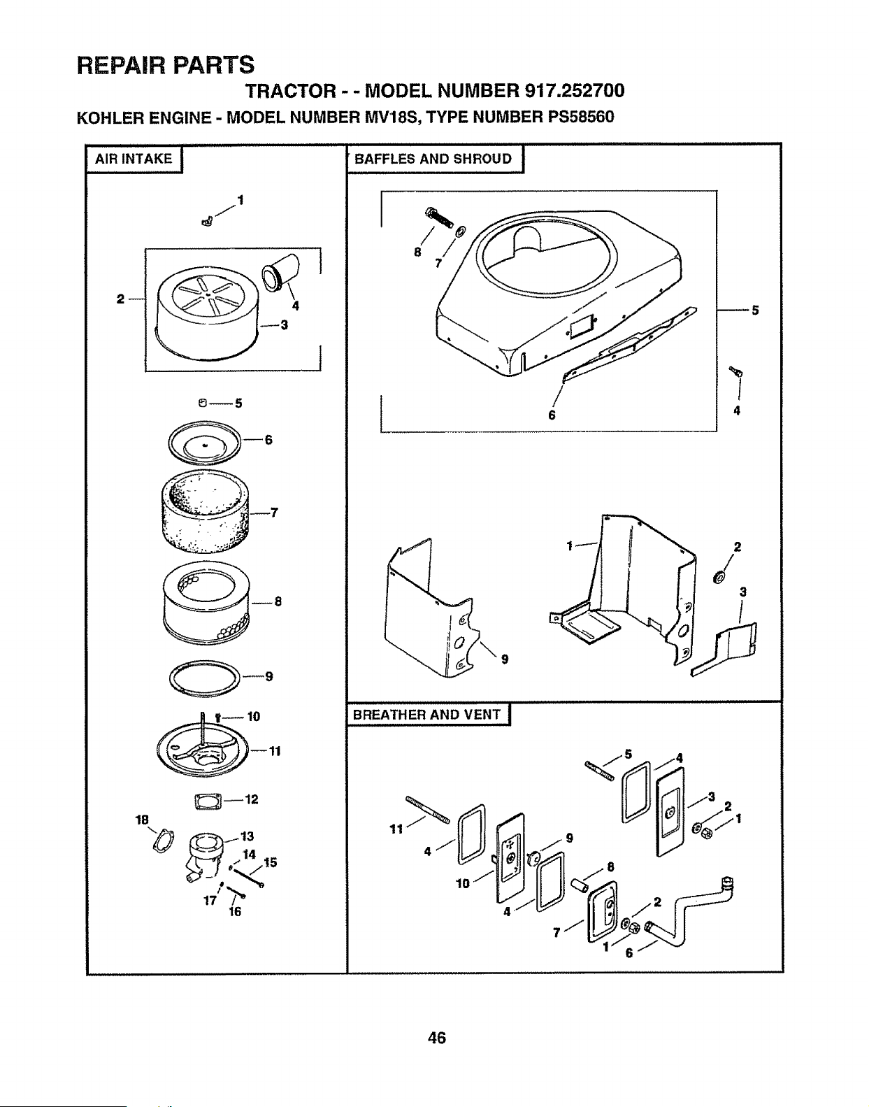
REPAIR PARTS
TRACTOR - - MODEL NUMBER 917.252700
KOHLER ENGINE - MODEL NUMBER MV18S, TYPE NUMBER PS58560
1
2_
_7
1B
/13
_" 14 15
16
i
o,,F_,_A.os.._ouD.,:,I
I
/
8
7
/
6
_5
%
I
4
9
BREATHER AND VENT J
46
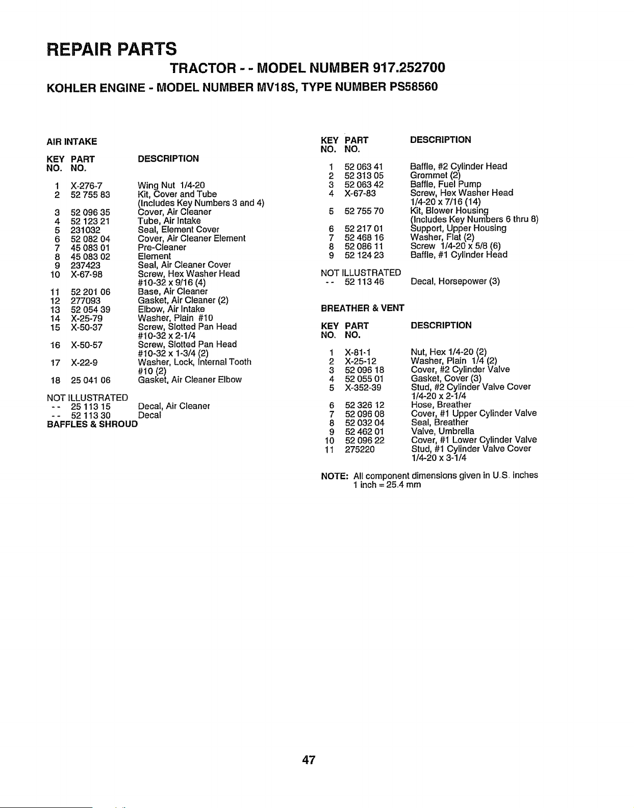
REPAIR PARTS
TRACTOR -- MODEL NUMBER 917.252700
KOHLER ENGINE - MODEL NUMBER MV18S, TYPE NUMBER PS58560
AIR INTAKE KEY PART DESCRIPTION
NO. NO,
KEY PART DESCRIPTION
NO, NO,
1 X-276-7 Wing Nut 1/4-20
2 52 755 83 Kit, Covet and Tube
(includes Key Numbers 3 and 4)
3 52 096 35 Cover, Air' Cleaner
4 52123 21 Tube, Air Intake
5 231032 Seal, Element Cover
6 52 082 04 Cover, Air Cleaner Element
7 45083 01 Pre-Cleaner
8 45 083 02 Element
9 237423 Seal, Air Cleaner Cover
10 X-67_98 Screw, Hex Washer Head
#10-32 x 9/16 (4)
11 52 201 06 Base, Air Cleaner
12 277093 Gasket, Air Cleaner (2)
13 52 054 39 Elbow, Air Intake
14 X-25-79 Washer, Plain #10
15 X-50-37 Screw, Slotted Pan Head
#10-32 x 2-1/4
!6 X-50-57 Screw, Slotted Pan Head
#10-32 x 1-3/4 (2)
17 X-22-9 Washer, Lock, In{ernal Tooth
#10 (2)
18 25 041 06 Gasket, Air Cleaner Elbow
NOT ILLUSTRATED
- - 25 1!3 15 Decal, Air Cleaner
-- 52 11330 Decal
BAFFLES & SHROUD
1 52 06341
2 5231305
3 52 063 42
4 X-67-83
5 52 755 70
6 52 217 01
7 52 468 16
8 52 086 11
9 52 124 23
NOT ILLUSTRATED
-- 52 11346
Baffle, #2 Cylinder Head
Grommet (2)
Baffle, Fuel Pump
Screw, Hex Washer Head
114`20 x 7/16 (14)
Kit, Blower Housing
nciudes Key Numbers 6 thru 8)
upport, Upper Housing
Washer, Flat (2)
Screw 1/4-20 x 5/8 (6)
Baffle, #1 Cylinder Head
Decal, Horsepower (3)
BREATHER & VENT
KEY PART
NO, NO.
DESCRIPTION
1
2
3
4
5
X-81-1
X-25-12
52 096 18
52 055 ot
X-352-39
6 52326 I2
7 52096 08
8 5203204
9 52 462 01
10 52 096 22
11 275220
Nut, Hex 1/4-20 (2)
Washer, Plain 1/4 (2)
Cover, #2 Cylinder Valve
Gasket, Cover (3)
Stud, #2 Cylinder Valve Cover
t/4-20 x 2-1/4
Hose, Breather
Cover, #1 Upper Cylinder Valve
Seal, Breather
Valve, Umbrella
Cover, #1 Lower Cylinder Valve
Stud, #1 Cylinder Valve Cover
I/4-20 x 3-1/4
NOTE: All component dimensions given in U.S, inches
1 inch = 25.4 mm
47
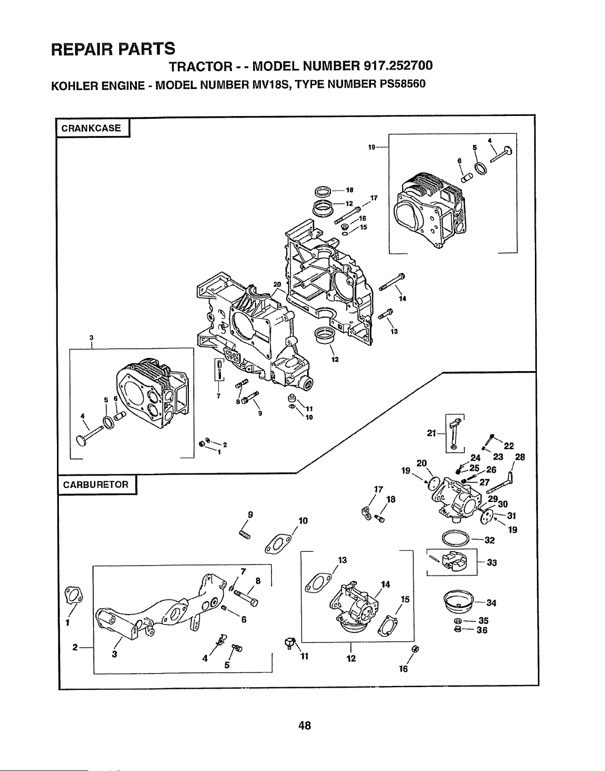
REPAIR PARTS
TRACTOR - - MODEL NUMBER 917.252700
KOHLER ENGINE - MODEL NUMBER MV18S, TYPE NUMBER PS58560
J _LI ,,,,,,ll illlll ii
J
CRANKCASE
19w
17
4
3
14
t3
7
8
11
48
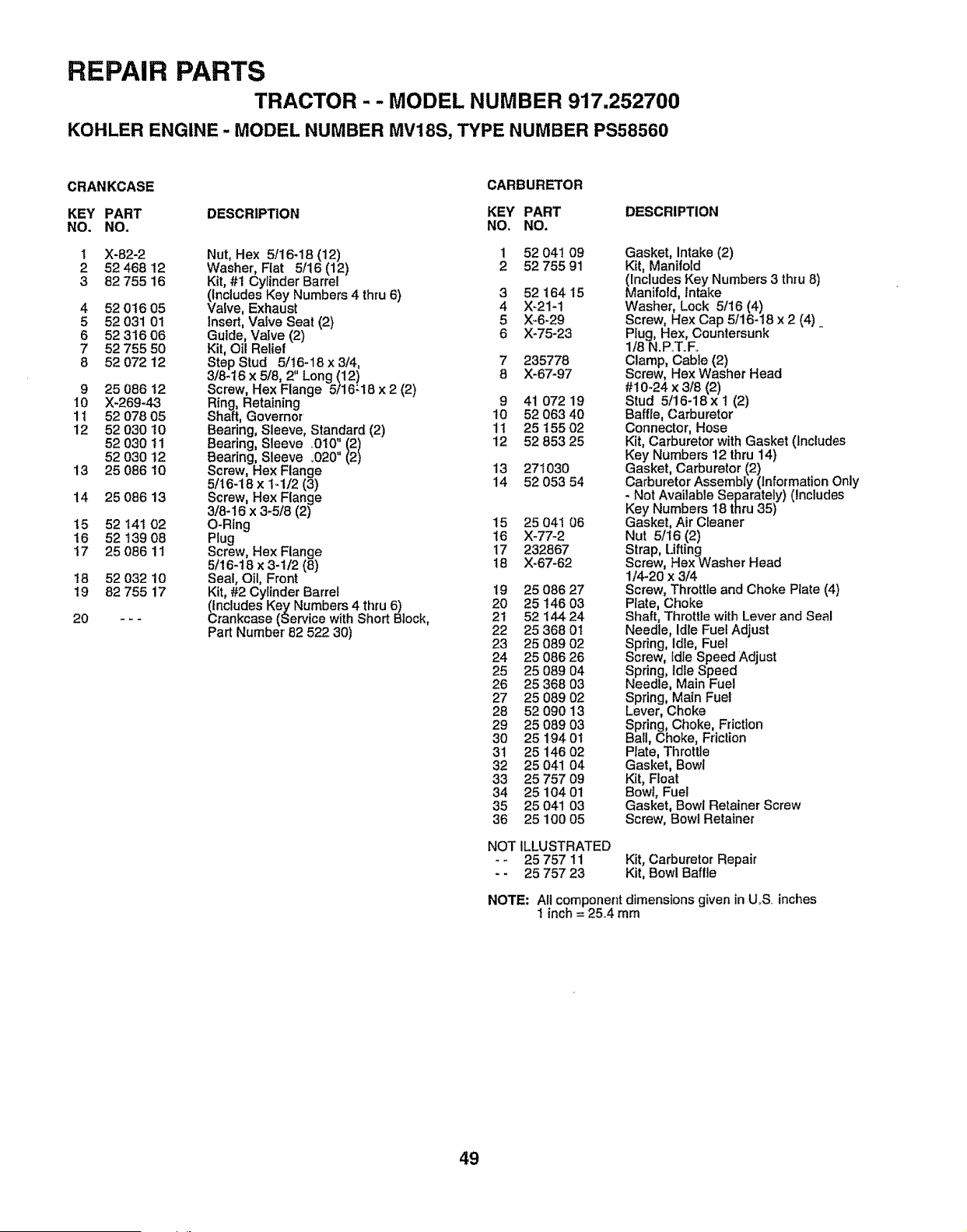
REPAIR PARTS
TRACTOR - - MODEL NUMBER 917.252700
KOHLER ENGINE - MODEL NUMBER MV18S, TYPE NUMBER PS58560
CRANKCASE
CARBURETOR
KEY PART DESCRIPTION KEY PART DESCRIPTION
NO. NO, NO, NO,
1 X-82-2 Nut, Hex 5/16-18 (12) 1 52 041 09
2 52 468 12 Washer, Flat 5116 (12) 2 52 755 91
3 82 755 16 Kit, #1 Cylinder Barrel
(includes Key Numbers 4 thru 6) 3 52 164 15
4 5201605 Valve, Exhaust 4 X-21-1
5 52 031 01 insert, Vafve Seat (2) 5 X-6_29
6 52 316 06 Guide, Vatve (2) 6 X-75-23
7 52 755 50 Kit, Oil Relief
8 52 072 12 Step Stud 5/16-18 x 3t4, 7 235778
3/8-16 x 5/8, 2" Long (12) 8 X-67-97
9 25 086 !2 Screw, Hex Flange 5/16"18 x 2 (2)
10 X-269-43 Ring, Retaining 9 41 072 19
11 52 078 05 Shaft, Governor 10 52 063 40
12 52 030 t0 Bearing, Sleeve, Standard (2) 11 25 t55 02
52 030 11 Bearing, Sleeve O10", (2) 12 52 853 25
52 030 t2 Bearing, Sleeve .020 (2)
13 25 086 10 Screw, Hex Flange 13 271030
5/16-18 x 1-1/2 (3) 14 52 053 54
14 25 086 13 Screw, Hex Flange
3/8-16 x 3-5/8 (2)
!5 52 t4! 02 O-Rlng !5 25 041 06
!6 52 t39 08 Plug 16 )(-77-2
17 25 086 11 Screw, Hex Flange 17 232867
5/16-18 x 3-t/2 (8) 18 )(-67-62
18 52 032 10 Seal, Oil, Front
19 82 755 17 Kit, #2 Cylinder Barrel 19 25 086 27
(Includes Key Numbers 4 thru 6) 20 25 146 03
20 - - - Crankcase (Service with Short Block, 21 52 144 24
Part Number 82 522 30) 22 25 368 01
23 25 089 02
24 25 086 26
25 25 089 04
26 25 368 03
27 25 089 02
28 52 090 13
29 25 089 03
30 25 194O1
31 25 14602
32 25 041 O4
33 25 757 09
34 25 10401
35 25 041 03
36 25 100 05
Gasket, intake (2)
Kit, Manifold
(Includes Key Numbers 3 thru 8)
Manifold, Intake
Washer, Lock 5/16 (4)
Screw, Hex Cap 5116-18 x 2 (4)
Plug, Hex, Countersunk
118N,P,,T.Fo
Clamp, Cable (2)
Screw, Hex Washer Head
#10-24 x 3/8 (2)
Stud 5/16-18x I (2)
Baffle, Carburetor
Connector, Hose
Kit, Carburetor with Gasket (Includes
Key Numbers 12 thru 14)
Gasket, Carburetor (2)
Carburetor Assembly (information Only
- Not Available Separately) (Includes
Key Numbers 18 thru 35)
Gasket, Air Cleaner
Nut 5t16 (2)
Strap, Lifting
Screw, Hex Washer Head
1/4-20 x 3/4
Screw, Throttle and Choke Plate (4)
Plate, Choke
Shaft, Throttle with Lever and Seal
Needle, Idle Fuel Adjust
Spring, Idle, Fuel
Screw, Idle Speed Adjust
Spring, Idle Speed
Needle, Main Fuel
Spring, Main Fuel
Lever, Choke
Spring, Choke, Friction
Ball, Choke, Friction
Rate, Threttle
Gasket, Bowl
Kit, Float
Bowl, Fuel
Gasket, Bowl Retainer Screw
Screw, Bowl Retainer
NOT ILLUSTRATED
-- 25 757 11 Kit, Carburetor Repair
- - 25 757 23 Kit, Bowl Baffle
NOTE: All component dimensions given in U.S. inches
1 inch = 25.4 mm
49
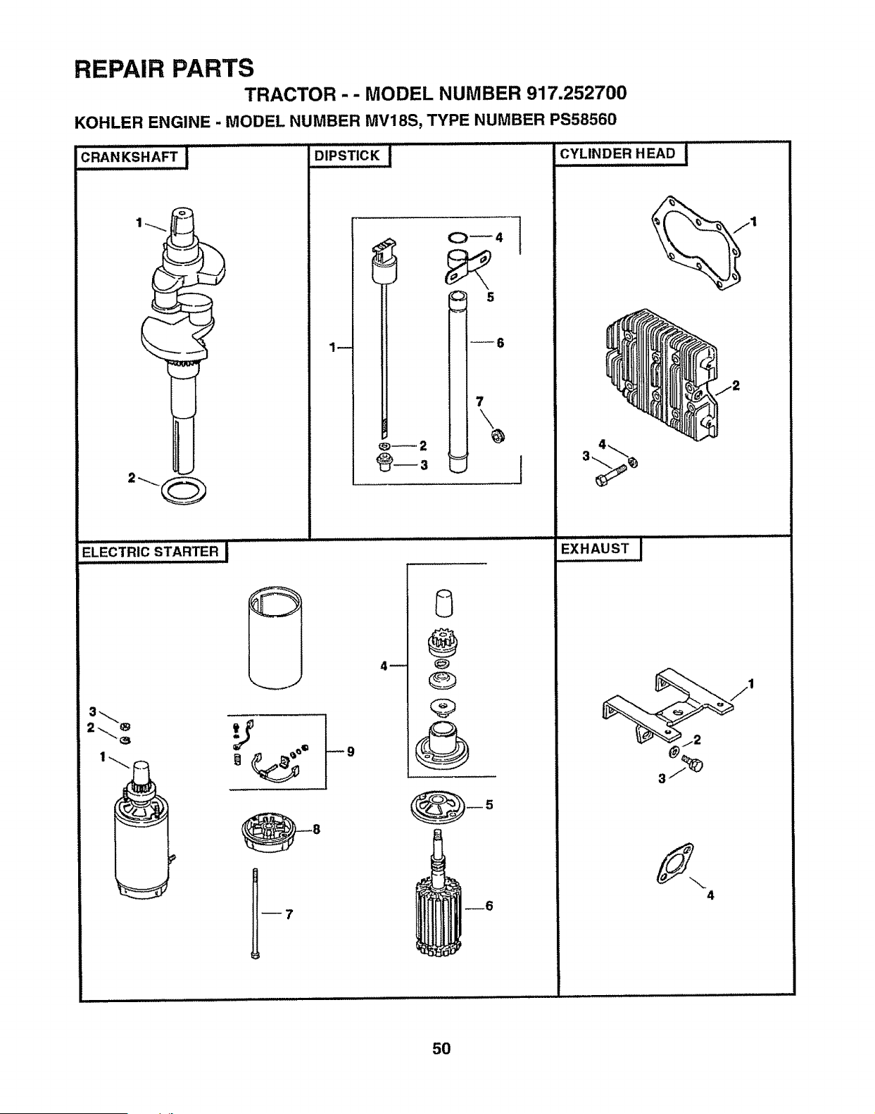
REPAIR PARTS
TRACTOR -- MODEL NUMBER 917.252700
KOHLER ENGINE - MODEL NUMBER MV18S, TYPE NUMBER PS58560
CRANKSHAFT !
I
L'ELECTRICSTARTER I
Rm
O_4
5
--6
7
J
0
@
Q
--6
J
CYLINDER HEAD i
4
5O
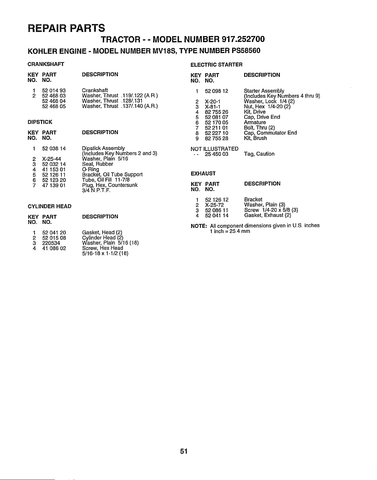
REPAIR PARTS
TRACTOR -- MODEL NUMBER 917.252700
KOHLER ENGINE - MODEL NUMBER MV18S, TYPE NUMBER PS58560
CRANKSHAFT
ELECTRIC STARTER
KEY PART DESCRIPTION KEY PART DESCRIPTION
NO. NO. NO, NO_
1 52 014 93
2 52468 03
52 468 04
52 468 05
DIPSTICK
KEY PART
NO. NO.
1 52038 14
2 X-25-44
3 52 032 14
4 41 15301
5 52 126 !1
6 52 123 20
7 47 139 01
CYLINDER HEAD
KEY PART
NO, NO.
Crankshaft
Washer, Thrust .119/.122 (AR)
Washe r, Thrust .128/. 131
Washer, Thrust .137/.140 (A.R.)
DESCRIPTION
Dipstick Assembly
(Includes Key Numbers 2 and 3)
Washer, Rain 5/16
Seal, Rubber
O-Ring
Bracket, Oil Tube Support
Tube, Oil Fill 11-7/8
Plug, Hex, Countersunk
3/4 N. P.T.F_
DESCRIPTION
Gasket, Head (2)
Cylinder Head (2)
Washer, Plain 5/16 (18)
Screw, Hex Head
5/16-18 x 1-1/2 (18)
1 52 04t 20
2 52 015 08
3 220534
4 41 086 02
2
3
4
5
6
7
8
9
52 098 12
X-20-1
X-81-1
82 755 26
52 081 07
52 170 05
52211 01
52 227 10
82 755 28
Starter Assembly
(Includes Key Numbers 4 thru 9)
Washer, Lock 1/4 (2)
Nut, Hex 1/4-20 (2)
Kit, Drive
Cap, Drive End
Armature
Bolt, Thru (2)
Cap, Commutator End
Kit, Brush
NOT ILLUSTRATED
- - 25 450 03 Tag, Caution
EXHAUST
KEY PART DESCRIPTION
NO. NO.
1
2
3
4
52 126 12 Bracket
X-25-72 Washer, Plain (3)
52 086 11 Screw 1/4-20 x5/8 (3)
52 041 14 Gasket, Exhaust (2)
NOTE: All component dimensions given in US inches
1 inch = 254 mm
51
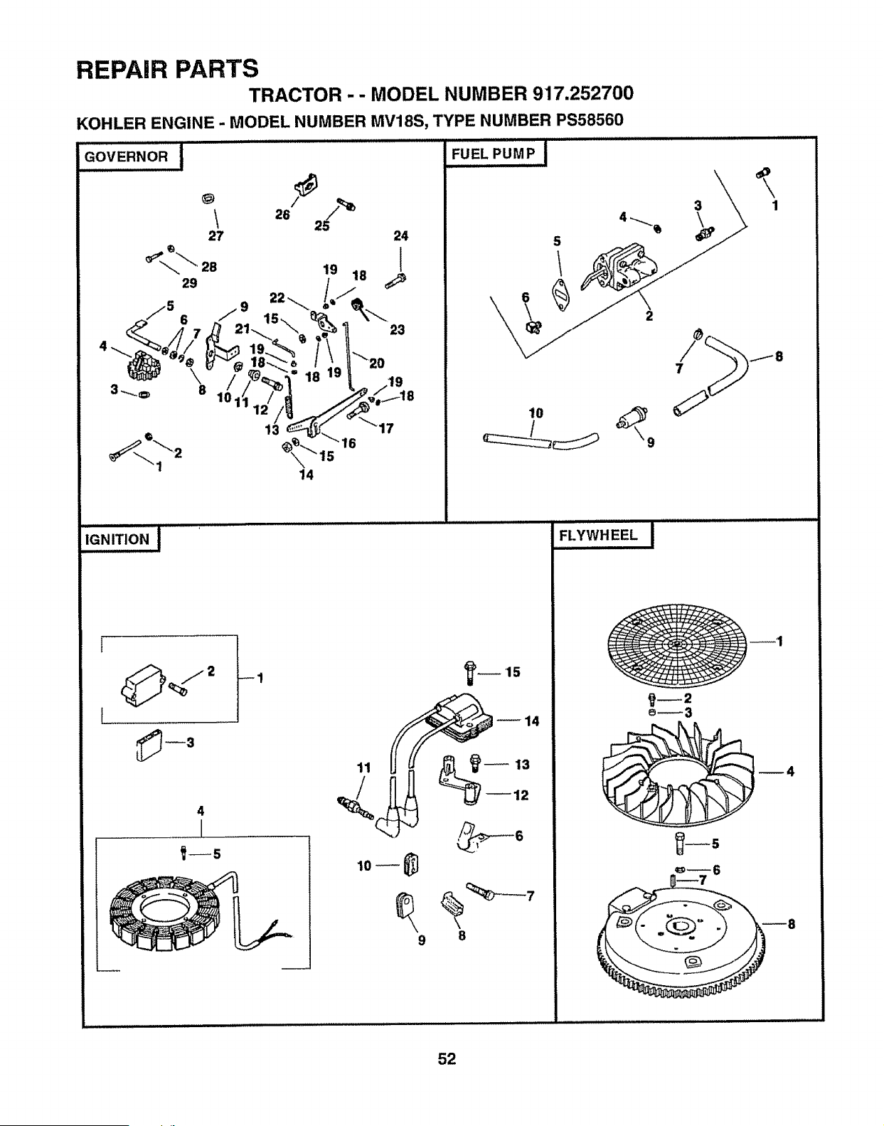
REPAIR PARTS
TRACTOR - - MODEL NUMBER 917,252700
KOHLER ENGINE - MODEL NUMBER MV18S, TYPE NUMBER PS58560
GOVERNOR J
t 28
27 24
19 18 -
29 _
22"-.. il//-,-.
.-5 --9 "_, _ _-
.,-.J 6 7 11.. flt__ \._.,
._ 7 F! 21-- \ "_'11 23
2/ ->o _ •
3...+ " I_.,+/7',1 +._,,./71,
14
iiiii iii iii i
IGNITION. i
, i i,Jll,Jlll i ,, i iiiii,JlllltU i i
4
I
1--5
11
9
FUEL PUMP i'
5
2
7
'-- 15
FLYWHEEL !
e_3
52
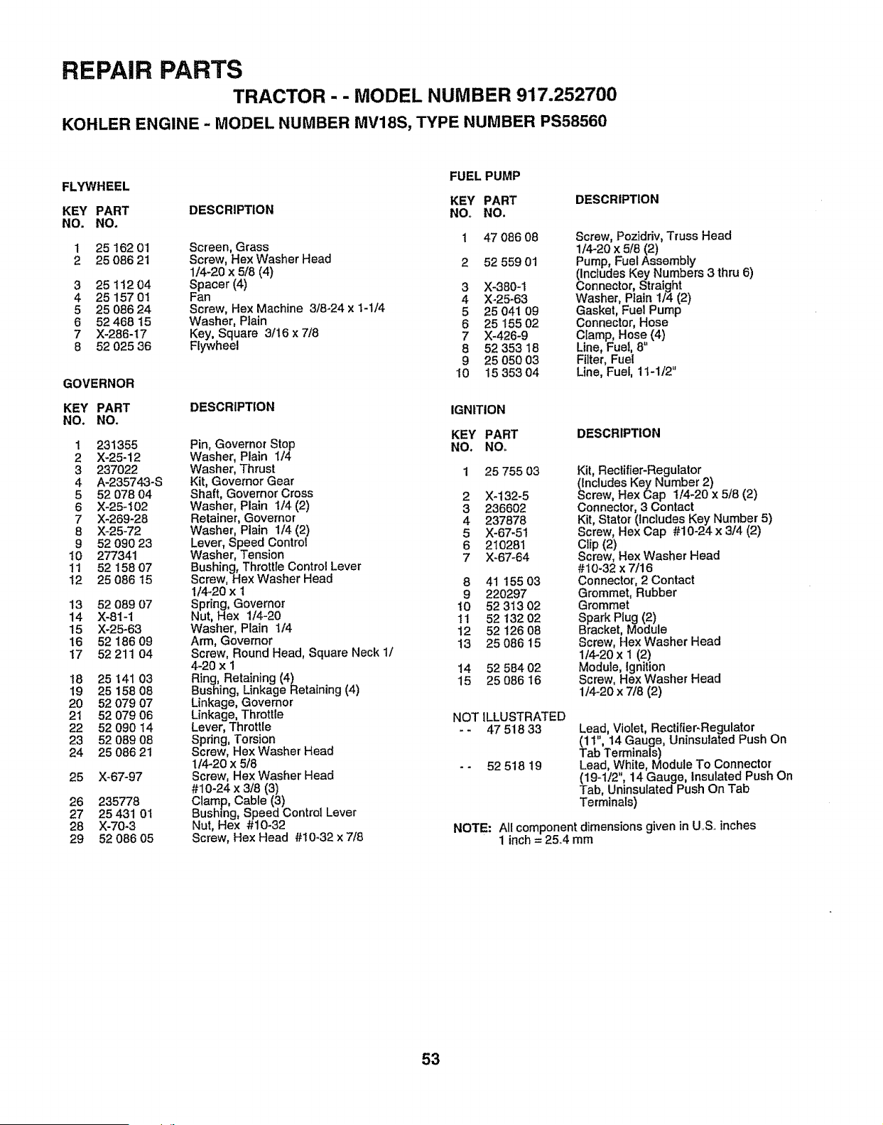
REPAIR PARTS
TRACTOR - - MODEL NUMBER 917.252700
KOHLER ENGINE - MODEL NUMBER MV18S, TYPE NUMBER PS58560
FLYWHEEL
FUEL PUMP
KEY PART DESCRIPTION
KEY PART DESCRIPTION NO+ NO.
NO. NO+
1 25 162 01 Screen, Grass 1 47086 08
2 25 086 21 Screw, HexWasher Head 2 52 559 01
1/4+20 x 5/8 (4)
3 25 112 04 Spacer (4) 3 X-380+1
4 25 157 01 Fan 4 X+25_63
5 25 086 24 Screw, Hex Machine 3/8+24 x 1-1/4 5 25 041 09
6 62 468 t5 Washer, Plain 6 25 155 02
7 X-286+17 Key, Square 3/16 x 7/8 7 X+426-9
8 52 025 36 Flywheel 8 52 353 18
9 25 05003
GOVERNOR 10 15 353 04
KEY PART DESCRIPTION IGNITION
NO. NO.
1 231355 Pin, Governor Stop
2 X+25-12 Washer, Plain 1/4
3 237022 Washer, Thrust
4 A-23574.3-S Kit, Governor Gear
5 52 07804 Shaft, Governor Cross
6 X-25-102 Washer, Plain t/4 (2)
7 X-269-28 Retainer, Governor
8 X+25-72 Washer, Plain 1/4 (2)
9 52 090 23 Lever, Speed Contro!
10 277341 Washer, Tension
11 52 158 07 Bushing, Throttle Control Lever
12 25 086 15 Screw, Hex Washer Head
1/4-20 x 1
13 52 089 07 Spring, Governor
14 X-81-1 Nut, Hex 1/4-20
15 X-25+63 Washer, Plain 1/4
16 52 186 09 Arm, Governor
t7 52 211 04 Screw, Round Head, Square Neck 1/
4-20 x 1
18 25 141 03 Ring, Retaining (4)
19 25 158 08 Bushing, Linkage Retaining (4)
20 52 079 07 Linkage, Governor
21 52 079 06 Linkage, Throttle
22 52 090 14 Lever, Throttle
23 52 089 08 Spring, Torsion
24 25 086 21 Screw, Hex Washer Head
1/4-20 x 5/8
25 X-67-97 Screw, Hex Washer Head
#10-24 x 3/8 (3)
26 235778 Clamp, Cable (3)
27 25 431 01 Bushing, Speed Control Lever
28 X-70+3 Nut, Hex #10-32
29 52 086 05 Screw, Hex Head #10+32 x 7/8
Screw, Pozidriv, Truss Head
1/4-20 x 5/8 (2)
Pump, Fuel Assembly
(Includes Key Numbers 3 thru 6)
Connector, Straight
Washer, Ptain 1/4 (2)
Gasket, Fuel Pump
Connector, Hose
Cramp, Hose (4)
Line, Fuel, 8
Filter, Fuel
Line, Fuel, 11-1/2"
KEY PART
NO+ NO+
DESCRIPTION
1 25 755 03
2 X+132+5
3 236602
4 237878
5 X-67-51
6 210281
7 X-67-64
8 41 15503
9 22o297
10 52 313 02
11 52 13202
12 52 126 08
13 2508615
14 52 584 02
15 25 086 16
NOT iLLUSTRATED
+- 47 518 33
-- 52 518 19
Kit, Rectifier-Regulator
(Includes Key Number 2)
Screw, Hex Cap I14+20 x 5/8 (2)
Connector +,3 Contact
Kit, Stator (Includes Key Number 5)
Screw, Hex Cap #10-24 x 3/4 (2)
Clip (2)
Screw, Hex Washer Head
#10-32 x 7/16
Connector, 2 Contact
Grommet, Rubber
Grommet
Spark Plug (2)
Bracket, Module
Screw, Hex Washer Head
1/4-2ox 1 (2)
Module, Ignition
Screw, Hex Washer Head
1]4-20 x 7/8 (2)
Lead, Violet, Rectifier-Regulator
(11", 14 Gauge, Uninsulated Push On
Tab Terminals)
Lead, White, Module To Connector
(19-112", 14 Gauge, Insulated Push On
Tab, Uninsulated Push On Tab
Terminals)
NOTE: All component dimensions given in U,S. inches
1 inch = 25+4 mm
53
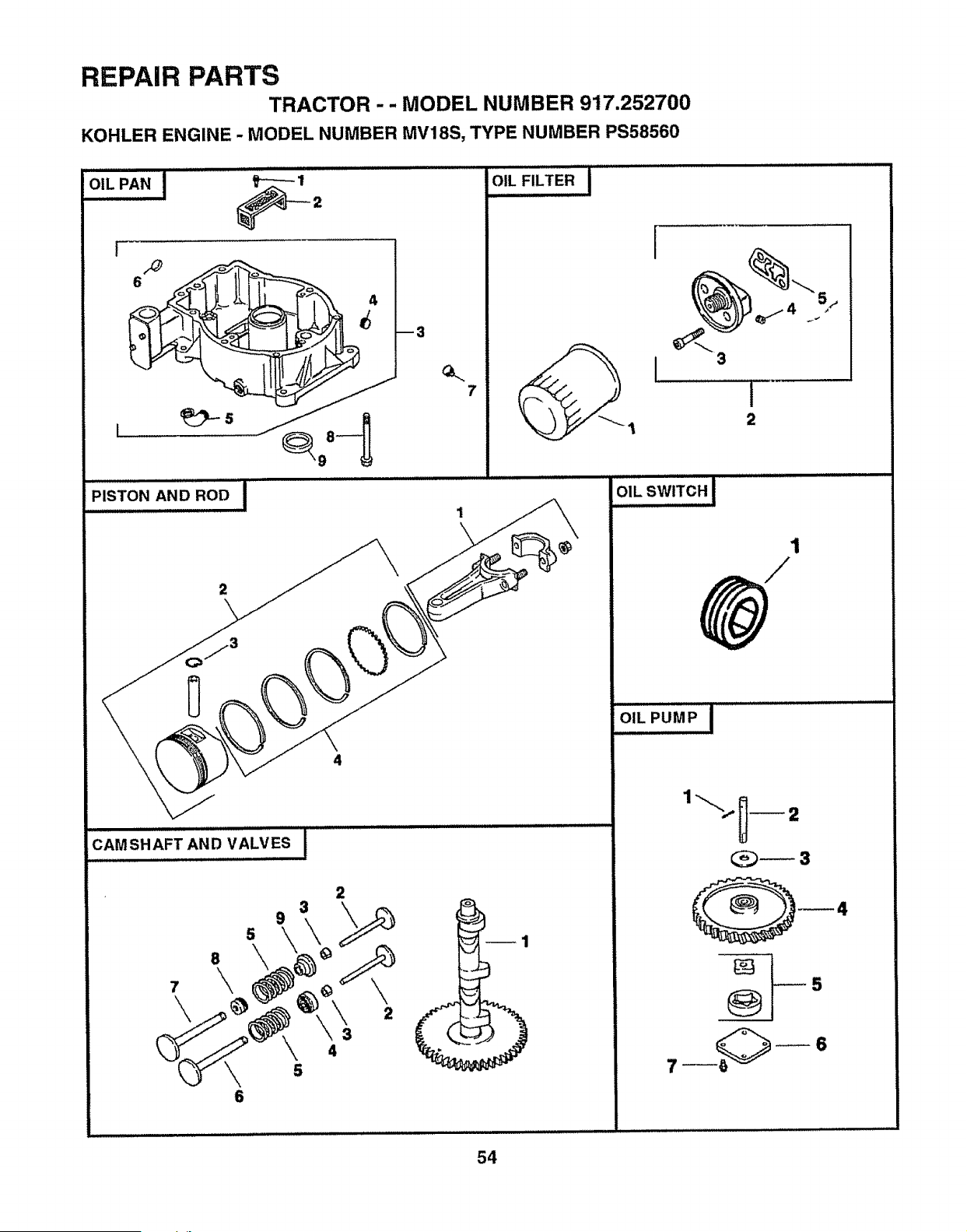
REPAIR PARTS
TRACTOR -- MODEL NUMBER 917.252700
KOHLER ENGINE - MODEL NUMBER MV18S, TYPE NUMBER PS58560
OiL PAN I ......... _ 2
[
PISTON AND ROD
m3
7
4
7
\
8
\
9
5
\
6
3
O,!L,,,,FILTER I
i
3
1
2
OIL SW!TCH l
i .................
1
olLP_Mp i ......
2
b_4
s
7 .... __ 6
54
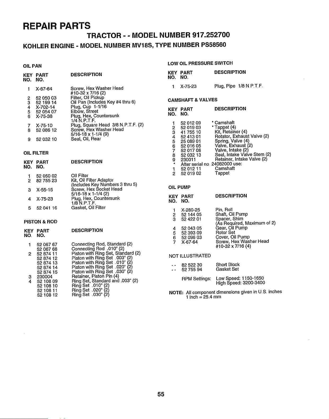
REPAIR PARTS
TRACTOR - - MODEL NUMBER 917.252700
KOHLER ENGINE - MODEL NUMBER MV18S, TYPE NUMBER PS58560
OIL PAN
KEY PART
NO. NO,
1 X-67-64
2 52 050 03
3 52 t99 14
4 )(-702-14
5 52 054 07
6 )(-75-38
7 X-75-10
8 52 066 12
9 52 032 10
OIL FILTER
KEY PART
NO. NO.
1 52050 02
2 82755 23
3 X-55-15
4 X-75-23
5 52 041 t6
PISTON & ROD
KEY PART
NO NO.
1 52 067 67
52 067 68
2 52 B74 11
52 874 12
52 874 13
52 874 14
52 874 15
3 230004
4 52 108 09
52 108 10
52 108 11
52 108 12
DESCRIPTION
Screw, Hex Washer Head
#10-32 x 7/I6 (2)
Filter, Oil Pickup
Oil Pan (Includes Key #4 thru 6)
Plug, Cup t-1/16
Elbow, Street
Plug, Hex, Countersunk
1/4 NoP.T,Fo
Plug, Square Head 3/8 NP_T.Fo (2)
Screw, Hex Washer Head
5/16q8 x 1-1/4 (9)
Seal, Oil, Rear
DESCRIPTION
Oil Filter
Kit, Oil Filter Adaptor
(Includes Key Numbers 3 thru 5)
Screw, Hex Socket Head
5/16-18 x 1-1/4 (2)
Plug, Hex, Countersunk
1/8 N.P.T,F.
Gasket, Oil Filter
DESCRIPTION
Connecting Rod, Standard (2)
Connecting Rod .010" (2)
Piston with Ring Set Standard (2)
Piston with Ring Set ,003' (2)
Piston with Ring Set _010",(2)
Piston with Ring Set _020' (2)
Piston with Ring Set .030" (2)
Retainer, Piston Pin (4)
Ring Set, Standard and .003" (2)
Ring Set .010 (2)
Ring Set ,020" (2)
Ring Set .030" (2)
LOW OIL PRESSURE SWITCH
KEY PART DESCRIPTION
NO. NO,
1 )(-75-23 Plug, Pipe I/8 N P.TF..
CAMSHAFT & VALVES
KEY PART DESCRIPTION
NO. NO.
1 52 01209 * Camshaft
2 52 019 03 * Tappet (4)
3 41 755 10 Kit, Retainer (4)
4 52 413 01 Rotator, Exhaust Valve (2)
5 25 089 01 Spring, Valve (4)
6 52 016 05 Valve, Exhaust (2)
7 52 017 08 Valve, Intake (2)
8 52 032 13 Seal, Intake Valve Stem (2)
9 230011 Retainer', Intake Valve (2)
• After serial no 24082000 use:
1 52 012 tl Camshaft
2 52 019 02 Tappet
OIL PUMP
KEY PART DESCRIPTION
NO, NO.
1 X-280-25 Pin, Roll
2 52 144 05 Shaft, Oil Pump
3 52 422 0! Spacer, Shim
(As Required, Maximum of 2)
4 52 043 05 Gear, Oil Pump
5 52 393 09 Rotor Set
6 52 096 03 Cover, Oil Pump
7 X_67-64 Screw, HexWasher Head
#I0-32 x 7/16 (4)
NOT ILLUSTRATED
- - 82 522 30
- - 52 755 94
Short Block
Gasket Set
RPM Settings: Low Speed: 1150-1650
High Speed: 3200-3400
NOTE: All component dimensions given in US.. inches
1 inch = 25.4 mm
55

SERVICE NOTES
56

NOTES
57

E NOTES
58

SUGGESTED GUIDE FOR SIGHTING SLOPES FOR SAFE OPERATION
SIGHTING
GUIDE
"-- .CU:r
ONLY RIDE UP AND DOWN HILL,
NOT ACROSS HILL
SIGHT AND HOLD THIS LEVEL WITH
SKY LINE OR TREE.
/
15° MAX.
IlJl I IIl'lllJJJl!l IIIII T .......
_i A Operate your Tractor up and down the face of slopes (not I
_1 _i,_ greater than 15°), never across the face. Make turns gradu-
a! O ally to prevent hppmg or loss of control. Exercise extreme i
_1 caution when changing direction on slopes. !
OWNER'S
MANUAL
MODEL NO.
917.252700
IF YOU NEED
REPAIR SERVICE
OR PARTS:
FOR REPAIR SERVICE, CALL
THIS TOLL FREE NUMBER:
1-800-4-REPAIR
(1-800-473-7247)
FOR REPLACEMENT PARTS
INFORMATION AND
ORDERING, CALL THIS
TOLL FREE NUMBER:
1-800-FON-PART
(1-800-366-7278)
FOR CONSUMER ASSISTANCE
HOT LINE, CALL THIS
TOLL FREE NUMBER:
1-800-659-5917
CRA AN®
18.0 HP
ELECTRIC START
3 in One Convertible
42" MOWER
6 SPEED TRANSAXLE
LAWN TRACTOR
Each tractor has its own model number. Each engine has
its own model number.
The model number for your tractor will be found on the
model plate located under the seat_
The model number for your engine will be found on the
blower housing of the engine.
All parts listed herein may be ordered from any Sears,
Roebuck and Co. Service Center/Department and most Re-
tail Stores.
WHEN ORDERING REPAIR PARTS, ALWAYS GIVE THE
FOLLOWING INFORMATION:
• PRODUCT - TRACTOR
° MODEl. NUMBER - 917.252700
° ENGINE MODEL NO.- MV18S- PS58560
° PART NUMBER
° PART DESCRIPTION
Your Sears merchandise has added value when you
consider Sears has service units nationwide staffed with
Sears trained technicians.., professional technicians
specifically trained to insure that we meet our pledge to
you, we service what we sell.
147197 Rew 3 06.28.95 Printed in U.S.A.
IIIIIIIIIIIIIIIIIIIIIIIIIIIIIll


