PRO.FORM"
6E/ARS
Model No. 831.297644
Serial No.
The serialnumbercanbefoundinthe
locationshownbelow.Writetheserial
numberinMespaceabove.
Ex _-- R C i S t=-
EO U I P r_l _=" N T
HELPLINE!
1-800-736-6879
USER'S MANUAL
SEARS, ROEBUCK AND CO., HOFFMAN ESTATES, IL 60179

Pi O:FORM"
TABLE OF CONTENTS
IMPORTANT PRECAUTIONS ................
BEFORE YOU BEGIN ......................
ASSEM'BLY ... ; ..........................
OPERATION AND ADJUSTMENT ............
HOW TO FOLD AND MOVE THE TREADMILL ..
TROUBLE-SHOOTING AND STORAGE ........
• = ..° 6oo1,=oo.o• • =° • .° ,,,,totQ .... ,,,•
• •°•.°. •• • ...°. • .. •••.•• • • o..,.°o°o.oo.
• *•o°o•.• •
.°..•.o . •
• • •••••.*.••.ooo°•Q
oo,.•.°.o•_°°.•**•oo °•o•••oo•.o.°o o.•
oo••leoo.o_
••o•o•.o,°7
......... 10
......... 12
CONDITIONING GUIDELINES ... .. - 14._o •o°oo*•_°°oto*,.=..•..oQ-°-o--ooo••,o°-°--•oo-oo-,.•o-°
ORDERING REPLACEMENT PARTS .................................................. Back Cover
FULL 90 DAY WARRANTY ............. Back Cover• o.•..oo_ t•* ... • =*,Dec ========================
•. Note: An EXPLODED DRAWING and a PART LIST are attached to the center of this manual. S,",vethe
EXPLODED DRAWING and PART LIST for future reference.
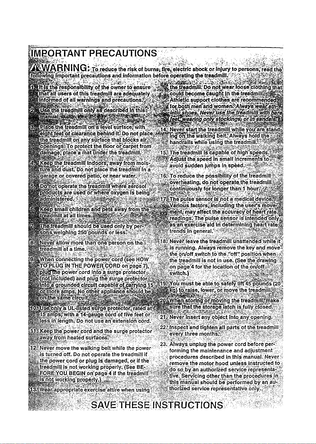
PRECAUTIONS-:" :_'"..
INSTRUCTIONS_
BEFORE YOU BEGIN
Thank you for selectingthe uniquePROFORM ° 580si
treadmill:The 580si treadmillblends advanced technol-
ogy with innovative stylingto let you enjoy an excellent
form ofcardiovascular exemise in the convenience and
privacyofyour home. The 580si offers an impressive
array of features to make yourworkouts more enjoy-
able and effective. Andwhen you're notexercising, the
580si can be folded up, requiringless than half the floor
space of othertreadmills.
For your benefit, read this manual carefully before
using the treadmill. Ifyou have additional questions,
please call our toll-free HELPLINE at 1-800-736-6879,
Monday through Saturday, 7 a.m, until7 p.m. Central
Time (excluding holidays). To help us assistyou,
please note the productmodel number and sedal num-
ber before calling. The model number of the treadmill
is831.297644. The sedal number can be found on a
decal attached tothe treadmill (see the front cover of
this manual for the location),
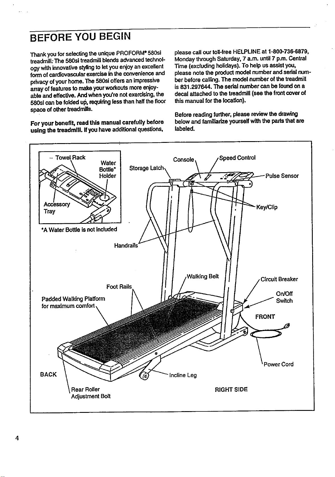
Before reading further, please review the drawing
below and familiarize yourself with the pads that are
labeled.
-- Towel Rack
Tray
Water
Bottle*
Holder
Storage Latch_
Console
*A Water Bottle Is not included
Handrails
Foot Rails
Padded Walking Platform
for maximum comfort
Circuit Breaker
On/Off
Switch
FRONT
BACK
Adjustment Bolt
RIGHT SIDE
4
ASSEMBLY
Assembly requires two people. Set the treadmill in a cleared area and remove all packing materials. Do not dis-
pose of the packing materials until assembly is completed. Tools required for assembly: The included allen
wrench _ and your phillips screwdriver _ and two adjustable wrenches _;;=:_::2_ •
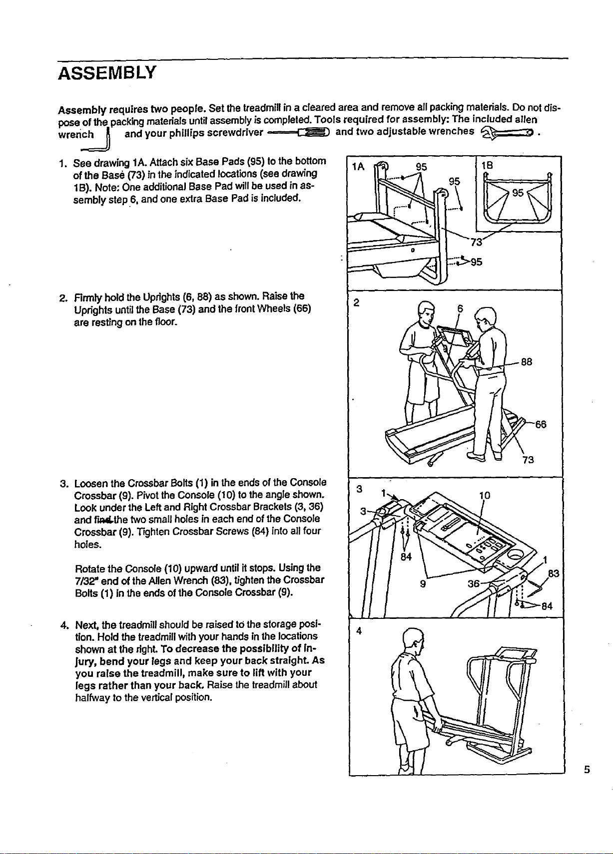
1. See drawing 1A. Attach six Base Pads (95) to the bottom 1A i _ 95 1B
of the Base (73) in the indicated locations (see drawing _ , 95 _..._ _F._t /1B). Note: One additional Base Pad will be used in as- _',,.J t , _ \
sembly step 6, and one extra Base Pad is included.
i
2. Firmly hold the Uprights (6, 88) as shown. Raise the
Uprights until the Base (73) and the frontWheels (66)
are resting on the floor.
3. Loosen the Crossbar Bolts (1) in the ends of the Console
Crossbar (9). Pivot the Console (10) to the angle shown.
Look under the Left and Right Crossbar Brackets (3, 36)
and Fu_d,.thetwo small holes in each end of the Console
Crossbar (9). Tighten Crossbar Screws (84) intoall four
holes.
Rotate the Console (10) upward until itstops. Using the
7/32" end of the Allen Wrench (83), tighten the Crossbar
Bolts (1) in the ends of the Console Crossbar (9).
4. Next, the treadmill should be raised tOthe storage posi-
tion. Hold the treadmill with your hands in the locations
shown at the righLTo decrease the possibility of In-
Jury, bend your legs and keep your back straight. As
you raise the treadmill, make sure to lift with your
legs rather than your back, Raise the treadmill about
halfway to the vertical position.
: ::;_>g5
2
84 _%.V::_-_/1
_/"._ >-'-..-,.3/ 83
,11 //-/j
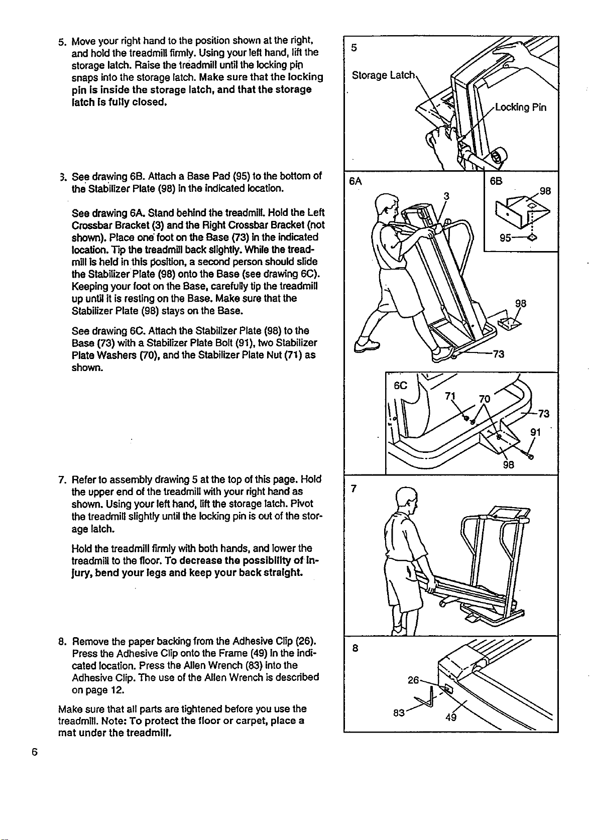
5. Move your right hand to the positionshown at the right,
and hold the treadmill firmly. Using your lefthand, lift the
storage latch. Raise the treadmill until the lockingpiD
snaps into the storage latch. Make sure that the locking
pin Is inside the storage latch, and that the storage
latch is fully closed.
5.
See drawing 6B. Attach a Base Pad (95) to the bottom of
the Stabilizer Plate (98) in the indicated location.
See drawing 6A. Stand behind the treadmill. Hold the Left
Crossbar Bracket (3) and the Right Crossbar Bracket (not
shown). Place one foot on the Base (73) in the indicated
location. Tip the treadmill back slightly.While the tread-
millis held in this I:_osftion,a second person shouldslide
the Stabilizer Plate (98) onto the Base (see drawing 6C).
Keeping your foot on the Base, carefully tip the treadmill
up until it is resting on the Base. Make sure thatthe
Stabilizer Plate (98) stays on the Base.
See drawing 6C. Attach the Stabilizer Plate (98) to the
Base (73) with a Stabilizer Plate Bolt (91), two Stabilizer
Plate Washers (70), and the Stabilizer Plate Nut (71) as
shown.
.
Refer to assembly drawing 5 at the top of this page. Hold
the upper end of the treadmillwith your righthand as
shown. Using your left hand, liftthe storage latch. Pivot
the treadmill slightlyuntilthe locking pin isout of the stor-
age latch.
Hold the treadmill firmly with bothhands, and lower the
treadmill to the floor. To decrease the possibility of in-
Jury, bend your legs and keep your back straight.
8. Remove the paper backing from the Adhesive Clip (26).
Press the Adhesive Clip ontothe Frame (49) In the Indi-
cated location. Press the Allen Wrench (83) intothe
Adhesive Clip. The use of the Allen Wrench is described
on page 12.
Make sure that all parts are tightened before you use the
treadmill. Note: To protect the floor or carpet, place a
mat under the treadmill.
_torage Latch _
6A
3
6B
95---_
6c i<
!"_ 71 70 . 73
_ 98
7
OPERATION AND ADJUSTMENT
THE PERFORMANT LUBE TM WALKING BELT
Your treadmill features a walking belt coated with
PERFORMANT LUBE", a high-performance lubricant.
IMPORTANT: Never apply silicone spray or other
substances to the walking belt or the walking plat-
form. They will deteriorate the walking belt and
cause excessive wear.
NOW TO PLUG IN THE POWER CORD
electric shock. This product is equipped with a cord
having an equipment-grounding conductor and a
grounding plug. Plug the power cord Into a surge
protector, and plug the surge protector Into an ap-
propriate outlet that Is properly Installed and
grounded In accordance with all local codes and
ordinances.
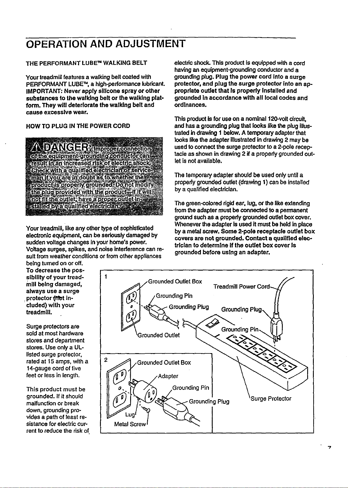
This product is for use on a nominal 120-volt circuit,
and has a grounding plug that looks like the plug illus-
trated in drawing I below. A temporary adaptarthat
]ooks like the adapter illustrated in drawing 2 may be
used to connect the surge protector to a 2-pole recep-
tacle as shown in drawing 2 if a properly grounded out-
let is not available.
The temporary adapter should be used only until a
properly grounded outlet (drawing 1) can be installed
by a qualified electrician.
Your treadmill, like any other type of sophisticated
electronic equipment, can be seriously damaged by
sudden voltage changes in your home's power.
Voltage surges, spikes, and noise interference can re-
suit from weather conditions or from other appliances
being turned on or off.
To decrease the pos-
sibility of your tread- 1
mill being damaged,
always use a surge
protector 0f_t in-
cluded) with your
treadmill.
Surge protectors are
sold at most hardware
stores and department
stores. Use only a UL-
listed surge protector,
rated at 15 stops, with a
14-gauge cord of five
feet or less in length.
This product must be
grounded. If it should
malfunction or break
down, grounding pro-
vides a path of least re-
sistance for electric cur-
rent to reduce the risk of.
The green-colored dgld ear, lug, or the like extending
from the adapter must be connected to a permanent
ground such as a propedy grounded outlet box cover.
Whenever the adapter is used it must be held in place
by a metal screw. Some 2-pole receptacle outlet box
covers are not grounded. Contact a qualified elec-
trician to determine If the outlet box cover Is
grounded before using an adapter.
/Grounded Outlet Box
• /Grounding Pin
unding Plug
3rounded Outlet
Treadmill Power Cord-...
Grounding
Grounded Outlet Box
J_.,/,Adapter
e.._._/_.0>'_ .Grounding Pin
(_ " , Grounding Plug
Metal Screw -_
Surge Protector
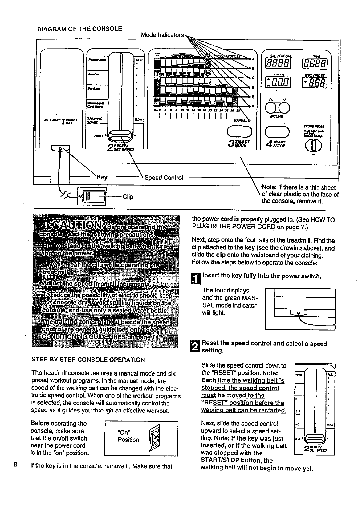
DIAGRAM OF THE CONSOLE
Y'_ -- Clip
Mode
IIIIIIIIIIIII
---\ Speed Control
\
_'Note: If there is a thinshee
\ of clear plastic on the face of
the console, remove it.
8
STEP BY STEP CONSOLE OPERATION
The treadmill console features a manual mode and six
preset workout programs. In the manual mode, the
speed of the walking belt can be changed with the elec-
tronic speed control. When one ofthe workout programs
is selected, the console willautomaticallycontrol the
speed as itguides you throughan effective workout.
console, make sure "On"
that the on/off switch Position
near the power cord
is in the "on" position.
If the key is in the console, remove it. Make sure that
the power cord is properly plugged in. (See HOW TO
PLUG IN THE POWER CORD on page 7.)
Next, step onto the foot rails of the treadmill. Findthe
clip attached to the key (see the drawing above), and
slide the clip ontothe waistband of your clothing.
Follow the steps below to operate the console:
g Insert the key fully into the power switch.
The four displays r-
and the green MAN-
/
UAL mode indicator
will light. L._ ..J
_'_ Reset the speed control and select a speed
setting.
Slide the speed controldown to
the "RESET" position..Note.-
Each time the walking belt ls
stooped, the soeed control
must be moved to the
"RESET" oosltlon before the
walkina belt can be restarted.
H
_L I II
Next, slide the speed control
upward to select a speed set-
ting. Note: If the key was just
Inserted, or if the walking belt
was stopped with the
START/STOP button, the
walking belt will not begin to move yet.
-1(:::===:31.
2r, rtm
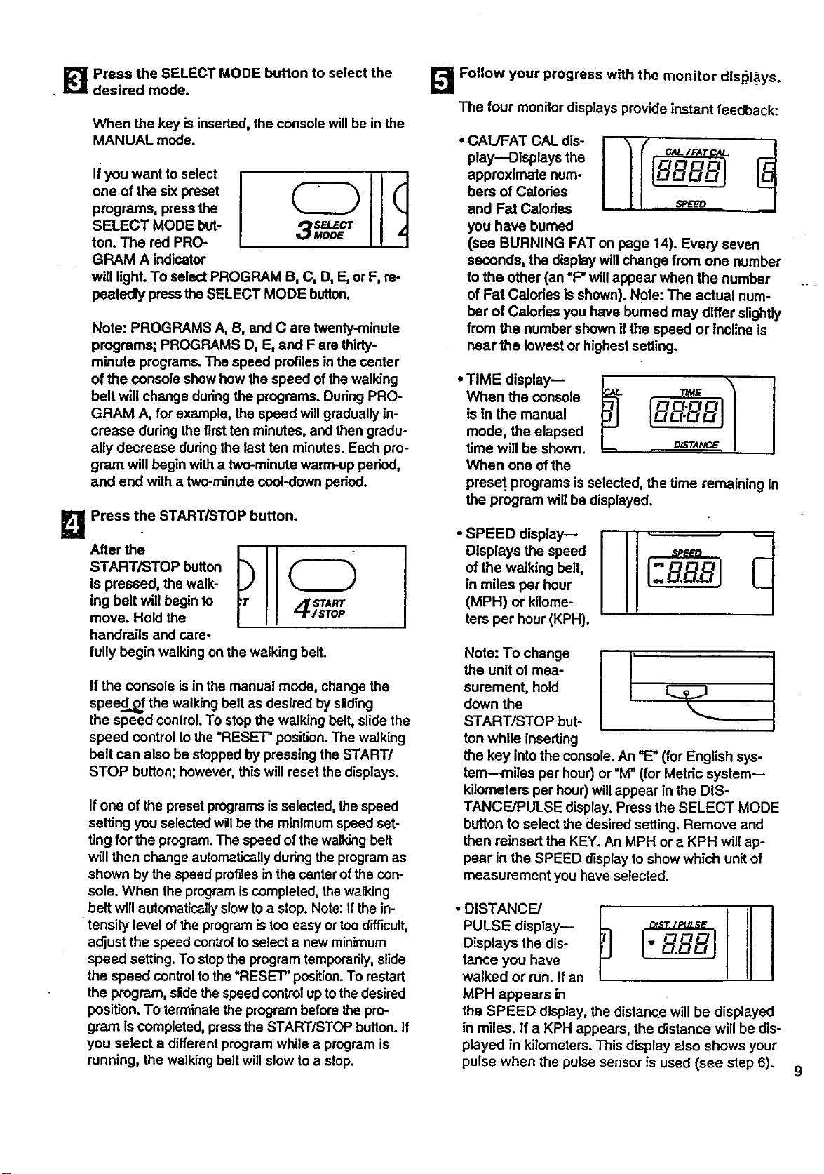
_'_ Press the SELECT MODE button to select the
desired mode.
When the key is inserted, the console willbe in the
MANUAL mode.
li you want to select
one of the six preset
programs, press the
SELECT MODE but-
ton. The red PRO-
GRAM A indicator
will light. To select PROGRAM B, C, D, E, or F, re-
peatedly press the SELECT MODE button.
Note: PROGRAMS A, B, and C are twenty-minute
programs; PROGRAMS D, E, and F are thirty-
minute programs. The speed profiles in the center
of the console show how the speed of the walking
belt will change duringthe programs. Dudng PRO-
GRAM A, for example, the speed willgradually in-
crease during the firstten minutes, and then gradu-
ally decrease during the last ten minutes. Each pro-
gram will begin witha two-minute warm-up pedod,
and end with a two-minute cool-down pedod.
_] Press the START/STOP button.
After the
START/STOP button
is pressed, the walk-
ing belt will begin to
move. Hold the
handrails and care-
fully begin walking on the walking belt.
If the console is in the manual mode, change the
speed...,_ the walking belt as desired by sliding
the speed control. To stop the walking belt, slide the
speed control to the "RESET" position. The walking
belt can also be stopped by pressing the START/
STOP button; however, this will reset thedisplays.
If one of the preset programs isselected, the speed
setting you selected willbe the minimum speed set-
ting for the program. The speed of the walking belt
willthen change automaticallyduring the programas
shown by the speed profilesin the center ofthe con-
sole. When the programiscompleted, the walking
belt will automaticallyslow to a stop. Note: Ifthe in-
tensity level ofthe program istoo easy or ton difficult,
adjust the speed controlto select a new minimum
speed setting. To stopthe program temporarily,slide
the speed controltothe "RESET" position. To restad
the program, sr_e the speed controlup tothe desired
position. To terminatethe program before thepro-
gram iscompleted, pressthe START/STOP button. If
you select a different program while a program is
running, the walking belt will slow to a slop.
[]Follow your progress with the monitor dlsl_l_ys.
The four monitordisplays provide instant feedback:
• CAIJFAT CAL dis-
play--Displays the
approximate num-
bera of Calodss
and Fat Calodes
you have burned
(see BURNING FATon page 14). Every seven
seconds, the display willchange from one number
to the other (an "F" willappear when the number
of Fat Calodss isshown). Note: The actual num-
ber of Calodes you have bumed may differ slightly
from the number shown if the speed or incline is
near the lowest or highest setting.
• TIME display--
When the console
is in the manual
mode, the elapsed
time will be shown.
When one of the
preset, programs is selected, the time remaining in
the program will be displayed.
• SPEED display--
Displays the speed
of the walking belt,
in miles per hour
(MPH) or kilome-
ters per hour (KPH).
Note: To change [ , [_
the unit of mea-
surement, hold
down the
START/STOP but-
ton while inseding
the key into the console. An =E"(for English sys-
tem---miles per hour) or "M" (for Metdc system--
kilometers per hour)will appear in the DIS-
TANCE/PULSE display. Press the SELECT MODE
button to select the desired setting. Remove and
then reinsert the KEY. An MPH or a KPH will ap-
pear in the SPEED display to show which unit of
measurement you have selected.
PULSE display--
Displays the dis-
tance you have
walked or run. If an
MPH appears in
I
the SPEED display, the distance will be displayed
in miles. If a KPH appears, the distance will be dis-
played in kilometers. This display also shows your
pulse when the pulse sensor is used (see step 6).
9
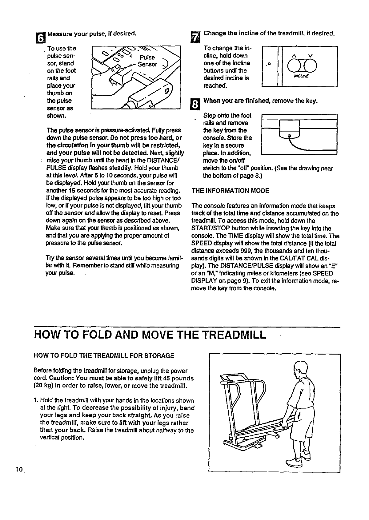
[]Measure your pulse, ifdesired.
To use the
pulse sen-
sor, stand
on the foot
rails and
place your
thumb on
the pulse
sensor as
shown.
The pulse sensor ispressure-activated.Fully pmsa
down the pulse sensor. Do not press too hard, or
the circulation in your thumb will be restricted,
and your pulse will not be detected. Next, slightly
raise your thumb unblthe head in the DISTANCE/
PULSE display flashes steadily. Hold your thumb
at this level. After 5 to 10 seconds, your pulsewill
be displayed. Hold your thumb on the sensorfor
another 15 seconds for the most accurate reading.
Ifthe displayed pulseappears to be too high or too
low,or ifyour pulse isnot displayed, lif_yourthumb
offthe sensor and allowthe display to reset. Press
down again on the sensoras descn'bed above.
Make sure that your thumb ispositioned as shown,
and thatyou are applyingthe properamount of
pressure to the pulsesensor.
Try the sensor several timesunt_lyou become famil-
Iar with it. Remember tostand stillwhile measuring
your pulse.
[]
To change the in-
cline, hold down
one of the incline
buttons until the
desired incline is
reached.
Change the incline of the treadmill, if desired.
.0
0
When you are finished, remove the key.
Step ohtothe foot
railsand remove
the key from the
console. Store the
key In a secure
place. In addition,
move the on/off
switch to the =off"posttlon.(See the drawingnear
the bottom of page 8.)
THE INFORMATION MODE
The console features an informationmode that keeps
track of the total time and distance accumulated on the
treadmill. To access this mode, hold down the
START/STOP button while insertingthe key into the
console. The TIME display willshow the total time. The
SPEED display will show the total distance (ifthe total
distance exceeds 999, the thousands and ten thou-
sands digits will be shown in the CAL/FAT CAL dis-
play). The DISTANCE/PULSE display will show an =E"
or an "M," ind'=catingmiles or kilometers (see SPEED
DISPLAY on page 9). To exit the information mode, re-
move the key from the console.
HOW TO FOLD AND MOVE THE TREADMILL
10
HOW TO FOLD THE TREADMILL FOR STORAGE
Before folding the treadmill for storage, unplug the power
cord. Caution: You must be able to safely lift 45 pounds
(20 kg) In order to raise, lower, or move the treadmill.
1. Hold the treadmill with your hands in the locations shown
at the right.To decrease the possibility of injury, bend
your legs and keep your back straight. As you raise
the treadmill, make sure to lift with your legs rather
than your back. Raise the treadmill about halh,tay to the
vertical position.
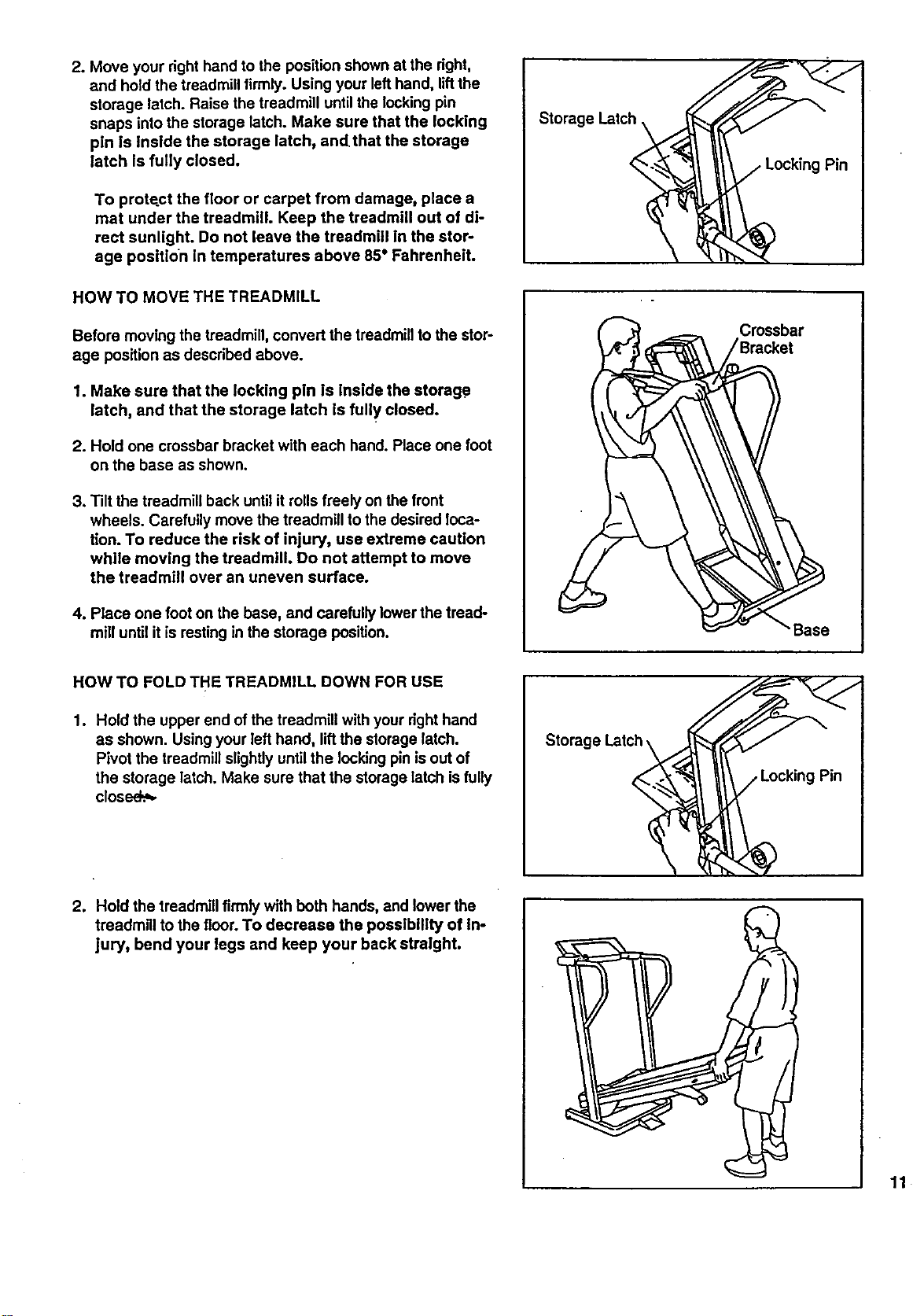
2. Move your right hand to the position shown at the dght,
and hold the treadmill firmly. Using your lefthand, liftthe
storage latch. Raise the treadmill untilthe lockingpin
snaps intothe storage latch. Make sure that the locking
pin Is inside the storage latch, andthat the storage
latch is fully closed.
To protect the floor or carpet from damage, place a
mat under the treadmill. Keep the treadmill out of di-
rect sunlight. Do not leave the treadmill In the stor-
age position in temperatures above 85 ° Fahrenheit.
HOW TO MOVE THE TREADMILL
Before moving the treadmill, convert the treadmillto the stor-
age position as described above.
1. Make sure that the locking pln Is inside the storag.e
latch, and that the storage latch is fully closed.
2. Hold one crossbar bracket with each hand. Place one foot
on the base as shown.
3. Tilt the treadmill back until itrolls freely on the front
wheels. Carefully move the treadmill to the desired loca-
tion. To reduce the risk of injury, use extreme caution
while moving the treadmill. Do not attempt to move
the treadmill over an uneven surface.
4. Place one foot on the base, and carefully lower the tread-
mill until itis resting in the storage position.
HOW TO FOLD THE TREADMILL DOWN FOR USE
1. Hold the upper end ofthe treadmill with your right hand
as shown. Using your left hand, lift the storage latch.
Pivot the treadmill slightlyuntil the locking pinis out of
the storage latch. Make sure that the storage latch is fully
closed_,
Storage Latch
t
Crossbar
•Base
Storage Latch.
Pin
2. Hold the treadmill firmlywith both hands, and lower the
treadmill to the floor. To decrease the posslbltity of In-
jury, bend your legs and keep your back stralght.
11
TROUBLE-SHOOTING AND STORAGE
Most treadmill problems can be solved by following the simple steps below. Find the symptom that ap-
plies, and follow the steps listed. If further assistance Is needed, call our toll-free HELPLINE at 1-800-736.
6879, Monday through Saturday, 7 e.m. until 7 p.m. Central Time (excluding holidays).
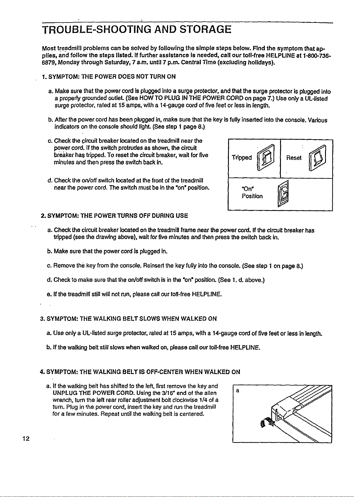
1. SYMPTOM: THE POWER DOES NOT TURN ON
a. Make sure that the power cord is plugged into a surge protector, and that the surge protector is plugged inlo
a properly grounded outlet. (See HOW TO PLUG IN THE POWER CORD on page 7.) Use only a UL-listed
surge protector, rated at 15 amps, with a 14-gauge cord of five feet or less in length.
b. After the power cord has been plugged in, make sure that the key is fully inserted into the console. Various
indicators on the console should light. (See step 1 page 8.)
c. Check the ¢imuit breaker located on the treadmill near the
power cord. If the switch protrudes as shown, the circuit
br-e_,kerha_ tripped. To reset the cimuitbreaker, wait for five
minutes and then press the switch back in.
d. Check the on/off switch located at the front of the treadmill
near the power cord. The switch must be in the "on"position.
Tripped
2. SYMPTOM: THE POWER TURNS OFF DURING USE
a. Check the circuit breaker located on the treadmill frame near the power cord. Ifthe circuit breaker has
tripped (see the drawing above), wait for five minutes and then press the switch back in.
b. Make sure that the power cord is plugged in.
c. Remove the key from the console. Reinsertthe key fully into the console. (See step 1 on page 8.)
d. Check to make sure that the on/off switchis in the "on" position. (See 1. d. above.)
e. If the treadmill stillwill not run, please call ourtoll-free HELPLINE.
3. SYMPTOM: THE WALKING BELT SLOWS WHEN WALKED ON
a. Use only a UL-llsted surge protector, rated at 15 amps, w'rtha 14-gauge cord of five feet or less in length.
b. If the walking belt stillslows when walked on, please call our toll-free HELPLINE.
12
4_.SYMPTOM: THE WALKING BELT IS OFF-CENTER WHEN WALKED ON
a. if the walking belt has shifted to the left,first remove the key and
UNPLUG THE POWER CORD. Using the 3/16" end of the allen
wrench, turn the left rear roller adjustment bolt clockwise 1/4 of a
turn. Plug in the power cord, insertthe key and run the treadmill
for a few minutes. Repeat until the walking belt is centered.
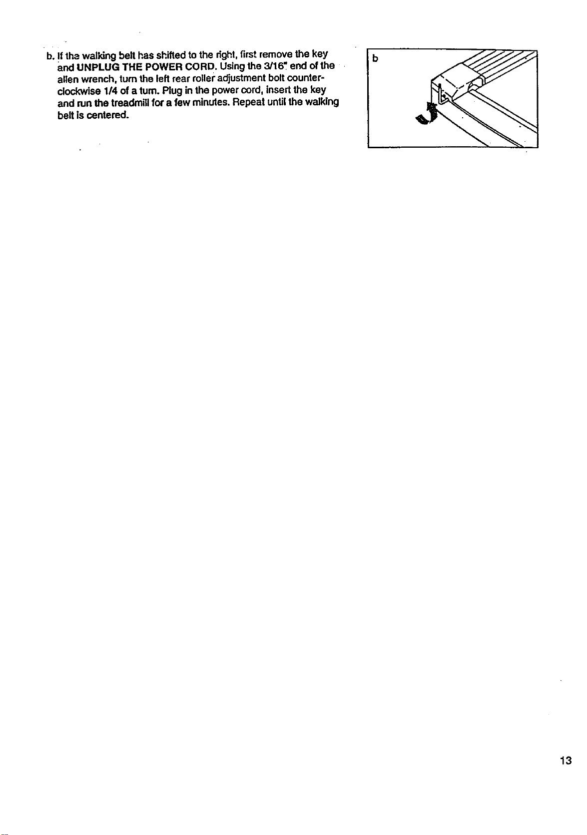
b. If the walking belt has shifted to the right,first remove the key
and UNPLUG THE POWER CORD. Using the 3/16".end of the
allen wrench, turn the left rear roller adjustment bolt counter-
clockwise 1/4 of a turn. Plug in the power cord, insert the key
and run the treadmig for a few minutes. Repeat until the walking
belt is centered.
b
13
CONDITIONING GUIDELINES
The following guidelines will helpyou to plan your ex-
ercise program. Remember--these are general guide-
lines. For more detailed informationabout exercise,
obtain a reputable book or consult yourphysician.
EXERCISE INTENSITY
Whether you want to bum fat, strengthen your cardio-
vascular system, 6r increase yourathletic perfor-
mance, you can tailor your exercise toyour specific
•. goals. The key to achieving the desired results is to ex-
ercise with the proper intensity.
Burning Pet
To burn fat effectively, you mustexercise at a relatively
low intensity level for a sustainedperiod of time.
During the first few minutes of exercise, your body
uses easily accessible carbohydrate calories for en-
ergy. Only after the first few minutesof exercise does
your body begin to use stored fat calories for energy.
Ifyour goal isto bum fat, set the speed control on the
console to FAT BURN tohelp you maintain the proper
intensitylevel. (See pages 8 and 9.)
Aerobic Exercise
If your goal is to strengthen your cardiovascular sys-
tem, your exercise must be =aerobic." Aerobic exercise
is activity that requires large amounts of oxygen for
prolonged periods of time. This increases the demand
on the heart to pump blood to the muscles, and on the
lungs to oxygenate the blood. The proper intensity
level for aerobic exercise can be found by using your
pulse as a guide. As you exercise, your pulse should
be kept at a level between 70% and 85% of your maxi-
mum possible heart rate. This is known as your train-
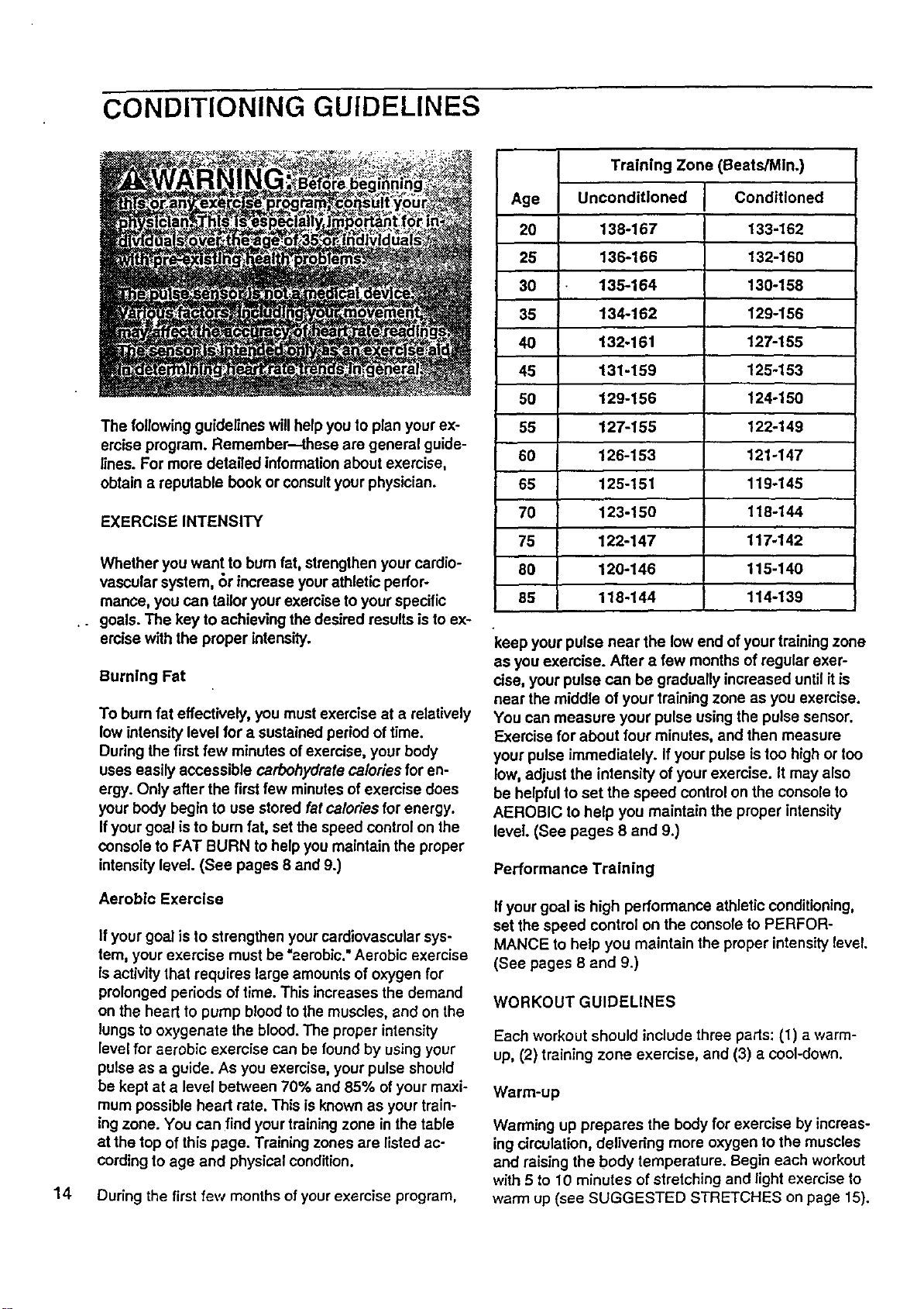
ing zone. You can find your training zone in the table
at the top of this page. Training zones are listed ac-
cording to age and physical condition.
14 During the first few months of your exercise program,
Training Zone (Beats/Mln.)
Age Unconditioned Conditioned
20 138-167 133-162
28 186-166 132-160
30 135-164 130-158
38 134-162 129-156
40 132o161 127-155
45 131-159 125-153
50 129-156 124-150
55 127-155 122-149
60 126-153 121-147
65 125-151 119o145
70 123-150 118-144
75 122-147 117-142
80 120-146 115-140
85 118-144 114-139
keep your pulse near the low end of your training zone
as you exercise. After a few months of regular exer-
cise, your pulse can be gradually increased until itis
near the middle of your training zone as you exercise.
You can measure your pulse using the pulse sensor.
Exercise for about four minutes, and then measure
your pulse immediately. If your pulse istoo high or too
low, adjust the intensity of your exercise. It may also
be helpfulto set the speed controlon the console to
AEROBIC to help you maintain the proper intensity
level. (See pages 8 and 9.)
Performance Training
If your goal is high performance athletic conditioning,
set the speed control on the console to PERFOR-
MANCE to help you maintain the proper intensity level.
(See pages 8 and 9.)
WORKOUT GUIDELINES
Each workout should include three pads: (1) a warm-
up, (2) training zone exercise, and (3) a cool-down.
Warm-up
Warming up prepares the body for exercise by increas-
ing circulation, delivering more oxygen to the muscles
and raising the body temperature. Begin each workout
with 5 to 10 minutes of stretching and light exercise to
warm up (see SUGGESTED STRETCHES on page 15).
Training Zone Exercise
After warming up, increase the intensity ofyour exer-
cise untilyour pulse is in your training zone for 20 to
60 minutes. (During the firstfew weeks of yourexer-
cise program, do not keep your pulse in yourtraining
zone fbr longer than 20 minutes.) Breathe regularly
and deeply as you exercise--never hold your breath.
Cool-down
Finish each workout with 5 to 10 minutes ofstretching
to cool down. This will increase the flexibilityof your.
muscles and willhelpto prevent post-exercise problems.
Exercise Frequency
To maintain or improve your condition, complete three
workouts each week, with at least one day of rest be-
tween workouts. After a few months, you may com-
plete up to five workouts each-week ifdesired.
The key to success is tomake exercise a regular and
enjoyable part of your everyday life.
SUGGESTED STRETCHES
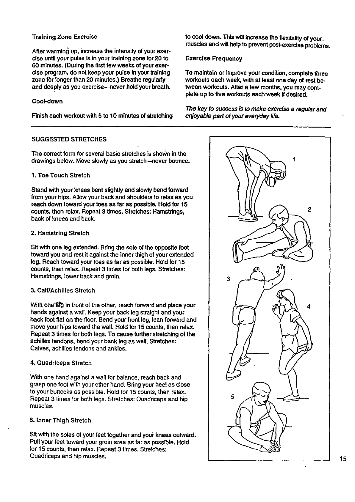
The correct form for several basic stretches is shown in the
drawings below. Move slowly as you stratch- never bounce.
1. Toe Touch Stretch
Stand with your knees bent slightly and slowlybend forward
from your hips. Allow your back and shoulders to relax as you
reach down toward your toes as far as possible. Hold for 15
counts, then relax. Repeat 3 times. Stretches: Hamstrings,
back of knees and back.
2. Hamstring Stretch
Sit with one leg extended. Bring the sole of the opposite foot
toward you and rest it against the inner thigh of your extended
leg. Reach toward your toes as far as possible;Hold for 15
counts, then relax. Repeat 3 times for bothlegs. Stretches:
Hamstrings, lower back and groin.
3, Calf/Achilles Stretch
With one'r_ in front of the other, reach forward and place your
hands against a wall. Keep your back leg straight and your
back foot flat on the floor. Bend your front leg, lean forward and
move your hipstoward the wall. Hold for 15 counts, then relax.
Repeat 3 times for both legs. To cause further stretching of the
achilles tendons, bend your back leg as well Stretches:
Calves, achilles tendons and ankles.
4. Quadriceps Stretch
With one hand against a wall for balance, reach back and
grasp one foot with your other hand. Sdng your heel as close
to your buttocks as possible. Hold for 15 counts, then relax.
Repeat 3 times for beth legs. Stretches: Quadriceps and hip
muscles.
5. inner Thigh Stretch
Sit with the soles ofyour feet together and youi"knees outward.
Pull your feet toward yourgroin area as far as possible, Hold
for 15 counts, then relax, Repeat 3 times. Stretches:
Quaddceps and hip muscles.
2
15
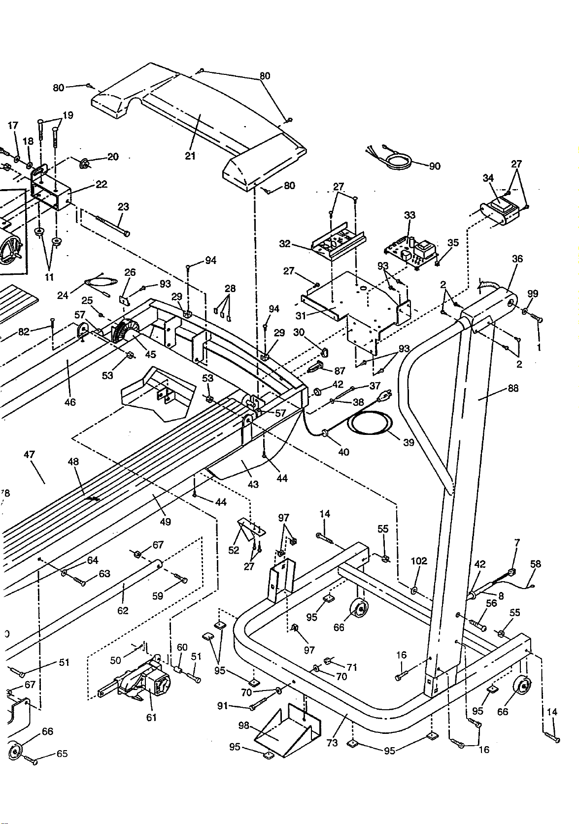
REMOVE THIS EXPLODED DRAWING
AND PART LIST FROM THEMANUAL
Save this EXPLODED DRAWING and PART LIST for future reference.
II I I
Note: Specifications are subject to change without notice. For information about ordering replacement oari._ _,
the back cover of this manl_!
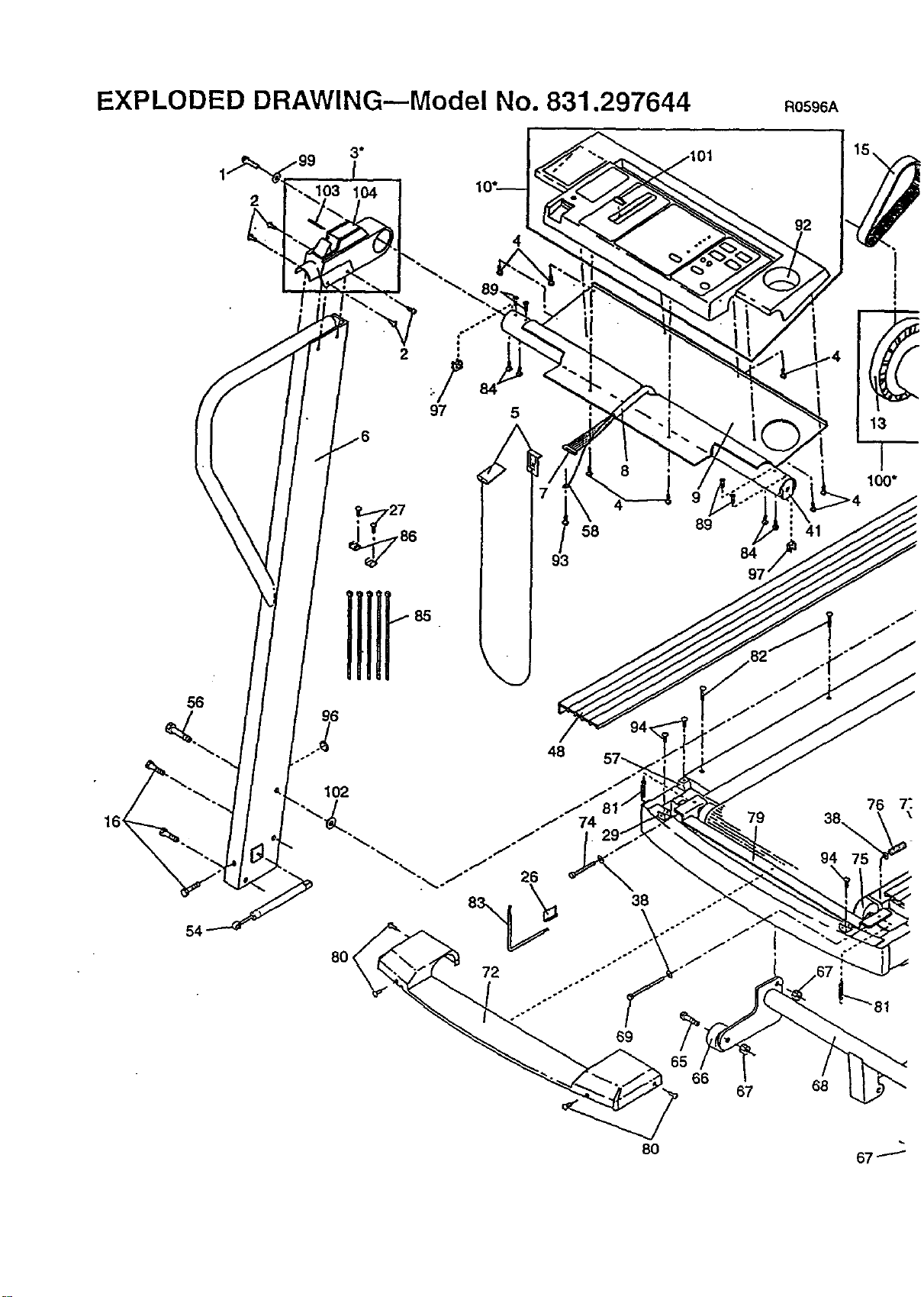
EXPLODED DRAWING--Model No. 831.297644 Ro596A
2
56
4
2
58
89
84
97
48
102
80
92
68
100"
67.--_
19
53
21
_.-94
28
87
46
49
6O
61
44
97
95
97
66
16
42
8
55
95 66
6
7
58
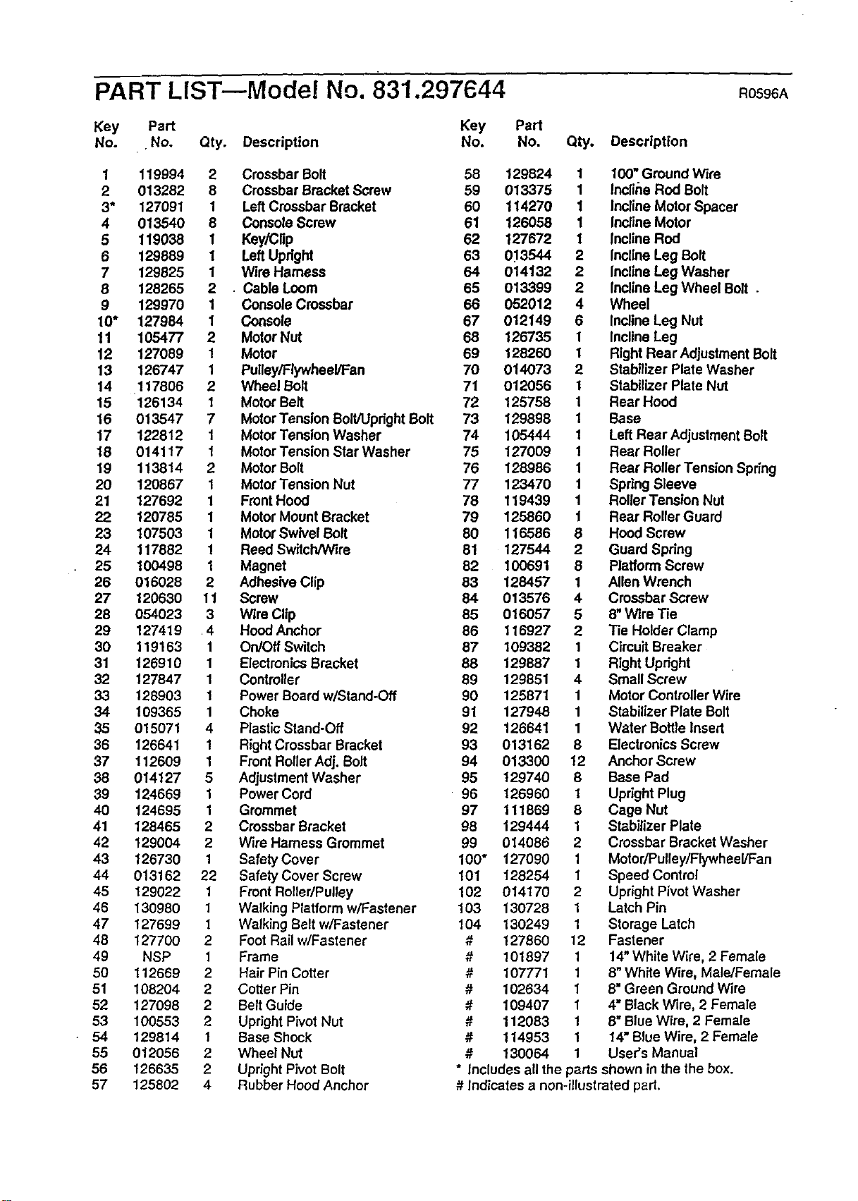
PART LIST--Mode! No. 831.297644 RoS96A
Key Part
No. .No. Qty. Description
Key Part
No. No. Qty. Description
1 119994 2 Crossbar Bolt
2 013282 8 Crossbar Bracket Screw
3" 127091 1 LeftCrossbar Bracket
4 013540 8 Console Screw
5 119038 1 Key/Clip
6 129889 1 Left Upright
7 129825 1 Wire Harness
8 128265 2 • Cable Loom
9 129970 1 Console Crossbar
10" 127984 1 Console
11 105477 2 Motor Nut
12 127089 1 Motor
13 126747 1 Pulley/Flywheel/Fan
14 117808 2 Wheel Bolt
15 126134 1 Motor Belt
16 013547 7 MotorTension Bolt/UprightBolt
17 122812 1 Motor Tension Washer
18 014117 1 MotorTension Star Washer
19 113814 2 Motor Bolt
20 120867 1 Motor Tension Nut
21 127692 1 Front Hood
22 120785 1 Motor Mount Bracket
23 107503 1 Motor Swivel Bolt
24 117882 1 Reed Switch/Wire
25 100498 1 Magnet
26 016028 2 Adhesive Clip
27 120630 11 Screw
28 054023 3 Wire Clip
29 127419 .4 Hood Anchor
30 119163 1 On/Off Switch
31 126910 1 ElectronicsBracket
32 127847 1 Controller
33 128903 1 Power Board w/Stand-Off
34 109365 1 Choke
35 015071 4 Plastic Stand-Off
36 126641 1 Right Crossbar Bracket
37 112609 1 Front Roller Adj. Bolt
38 014127 5 Adjustment Washer
39 124669 1 Power Cord
40 124695 1 Grommet
41 128465 2 Crossbar Bracket
42 129004 2 Wire Hamess Grommet
43 126730 1 Safety Cover
44 013162 22 Safety Cover Screw
45 129022 1 Front Roller/Pulley
46 130980 1 Walking Platform wlFastener
47 127699 1 Walking Belt w/Fastener
48 127700 2 Foot Rail wlFastener
49 NSP 1 Frame
50 112669 2 Hair Pin Cotter
51 108204 2 Cotter Pin
52 127098 2 Belt Guide
53 100553 2 Upright Pivot Nut
• 54 129814 1 Base Shock
55 012056 2 Wheel Nut
56 126635 2 Upright Pivot Bolt
57 125802 4 Rubber Hood Anchor
58 129824 1 100" Ground Wire
59 013375 1 Incliite Rod Bolt
60 114270 1 Incline Motor Spacer
61 126058 1 Incline Motor
62 127672 1 Incline Rod
63 0_13544 2 Incline Leg Bolt
64 014132 2 Incline Leg Washer
65 013399 2 Incline Leg Wheel Bolt .
66 052012 4 Wheel
67 012149 6 Incline Leg Nut
68 126735 1 Incline Leg
69 128260 1 Right Rear Adjustment Bolt
70 014073 2 Stabilizer Plate Washer
71 012056 1 Stabilizer Plate Nut
72 125758 1 Rear Hood
73 129898 1 Base
74 105444 1 Left Rear Adjustment Bolt
75 127009 1 Rear Roller
76 128986 1 Rear Roller Tension Spring
77 123470 1 Spring Sleeve
78 119439 1 Roller Tension Nut
79 125860 1 Rear Roller Guard
80 116586 8 Hood Screw
81 127544 2 Guard Spdng
82 100691 8 Platform Screw
83 128457 1 Allen Wrench
64 013576 4 Crossbar Screw
85 016057 5 8" Wire Tie
86 116927 2 Tie Holder Clamp
87 109382 1 Circuit Breaker
88 129887 1 Right Upright
89 129851 4 Small Screw
90 125871 1 Motor Controller Wire
91 127948 1 Stabilizer Plate Bolt
92 126641 1 Water Bottle Insert
93 013162 8 Electronics Screw
94 013300 12 Anchor Screw
95 129740 8 Base Pad
96 126960 1 Upright Plug
97 111869 8 Cage Nut
98 129444 1 Stabilizer Plate
99 014086 2 Crossbar Bracket Washer
100" 127090 1 Motor/Pulley/Flywheel/Fan
101 128254 1 Speed Control
102 014170 2 Upright Pivot Washer
103 130728 1 Latch Pin
104 130249 1 Storage Latch
# 127860 12 Fastener
# 101897 1 14" White Wire, 2 Female
" 107771 1 8" White Wire, Male/Female
Tt
# 102634 1 6" Green Ground Wire
# 109407 1 4" Black Wire, 2 Female
" 112083 1 8" Blue Wire, 2 Female
T,Z
# 114953 1 14" Blue Wire, 2 Female
# 130064 1 User's Manual
* Includes all the parts shown in the the box.
# Indicates a non-illustrated part.

SEARS
Model No. 831.297644
QUESTIONS?
If you find that:
• you need help assembling or
operating the PROFORM" 580si
treadmill
• a part is missing
• or you need to schedule repair
service
call our toll-free HELPLiNE
1-800-736-6879
Monday-Saturday, 7 am-7 pm
Central Time (excluding holidays)
REPLACEMENT
PARTS
If parts become worn and need
to be replaced, call the following
toll-free number
1-800-FON-PART
(1-800-366-7278)
The model number and serial number of your PROFORM" 580si
treadmill are listed.on a decal attached to the frame. See the front
cover of this manual to find the location of the decal.
All replacement parts are available for immediate purchase or
special order when you visit your nearest SEARS Service Center,
To request service or to Orderparts by telephone, call the toll-free
numbers listedat the left.
When requesting help or service, or ordedng pads, please be pre-
pared to provide the following information:
• The NAME OF THE PRODUCT (PROFORM =580si treadmill)
• The MODEL NUMBER OF THE PRODUCT (831.297644)
• The PART NUMBER OF THE PART (see the EXPLODED
DRAWING and PART LIST attached to the center of this manual)
• The DESCRIPTION OFTHE PART (see the EXPLODED DRAW-
ING and PART LIST attached to the center of this manual)
[ FULL 90 DAY WARRANTY ]
For 90 days from the date of purchase, iffailure occurs due to defect in material or workmanship in this
SEARS TREADMILL EXERCISER, contact the nearest SEARS Service Center throughout the United
States and SEARS will repair or replace the TREADMILL EXERCISER, free of charge.
This warranty does not apply when the TREADMILL EXERCISER is used commercially or for rental pur-
poses.
This warrantygives you specific legal rights, andyoumay also have other rightswhich vary fromstate
to state.
SEARS, ROEBUCK AND CO., DEPT. 817WA, HOFFMAN ESTATES, IL 60179
Part No. 130064 F00667-C R0596A Printed in USA © 1.996 Sears, Roebuck and Co.