
1
SmartRack
®
Enclosure
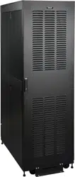
with Zone 4 Seismic Rating
Model: SR42UBZ4
(Series Number: AGAC7761)
Owner’s Manual
Important Safety Instructions 2
Overview 2
Feature Identification 3
Enclosure Installation 4
Preparation 4
Unpacking 4
Placement 5
Ground Connection 5
Enclosure Configuration 6
Adding or Removing Front and Rear Doors 6
Reversing Front Door 6
Adding or Removing Roof Panel 8
Adding or Removing Side Panels 8
Adjusting Mounting Rails and Cable Management Rails 9
Combining (Baying) Enclosures 10
Equipment Installation 11
Installing or Removing Cage Nuts 11
Specifications 12
Storage and Service 12
Warranty and Product Registration 12
Español 13
Français 25
Русский
37
1111 W. 35th Street, Chicago, IL 60609 USA • www.tripplite.com/support
Copyright © 2019 Tripp Lite. All rights reserved. All trademarks are the sole property of their respective owners.
PROTECT YOUR INVESTMENT!
Register your product for quicker service and ultimate peace of mind.
You could also win an ISOBAR6ULTRA surge protector—a $100 value!
www.tripplite.com/warranty

2
Important Safety Instructions
SAVE THESE INSTRUCTIONS
All sections of this manual contain instructions and warnings that should be followed during the installation and use of the SmartRack Enclosures
described in this manual. Read all instructions and warnings thoroughly before attempting to move, install or use the SmartRack Enclosures
described in this manual. Failure to comply will create a risk of personal injury and property damage and may invalidate the warranty.
• Keep the enclosure in a controlled indoor environment, away from moisture, temperature extremes, flammable liquids and gasses, conductive
contaminants, dust and direct sunlight.
• Leave adequate space at the front and rear of the enclosure for proper ventilation. Do not block, cover or insert objects into the external ventilation
openings of the enclosure.
• The enclosure is extremely heavy. Use caution when handling the enclosure. Do not attempt to unpack, move or install it unassisted. Use a
mechanical device such as a forklift or pallet jack to move the enclosure in the shipping container.
• Do not place any object on the enclosure, especially containers of liquid, and do not attempt to stack the enclosures.
• Inspect the shipping container and the enclosure for shipping damage. Do not use the enclosure if it is damaged.
• Leave the enclosure in the shipping container until it has been moved as close to the final installation location as possible.
• Install the enclosure in a structurally sound area with a level floor that is able to bear the weight of the enclosure, all equipment that will be installed
in the enclosure and any other enclosures and/or equipment that will be installed nearby.
• Install the cabinet securely to the building structure, using the shipping brackets as illustrated in the Enclosure Installation section of this
manual.
• Do not push the enclosure from the side panels to move it. Pushing from the side panels will cause a tipping hazard.
• Use caution when cutting packing materials. The enclosure could be scratched, causing damage not covered by the warranty.
• Save all packing materials for later use. Repacking and shipping the enclosure without the original packing materials may cause product damage
that will void the warranty.
• Do not re-ship the enclosure with additional equipment unless the enclosure was shipping with a special shock pallet (“SP1” models only). The
combined weight of the enclosure and the installed equipment must not exceed the load capacity of the pallet. Tripp Lite is not responsible for any
damage that occurs during re-shipment.
• Use of this equipment in life support applications where failure of this equipment can reasonably be expected to cause the failure of the life support
equipment or to significantly affect its safety or effectiveness is not recommended.
Overview
SmartRack Enclosures accommodate all standard 19-inch rackmount equipment, regardless of vendor, and ship fully assembled for quick and easy
deployment. They feature adaptable heavy-duty cabinets with variable mounting depths, making them ideal for servers. The cabinets include quick
release doors and side panels for convenient maintenance. Integrated baying hardware enables cost-effective, orderly and efficient expansion. Front
and rear doors and side panels are lockable.
The SR42UBZ4 is designed for use in earthquake zones. The enclosure features a welded construction, providing more security for use in unstable
environments. Reinforcing Zone 4 Seismic Brackets offer enhanced stability and protection with a Zone 4 seismic rating.

3
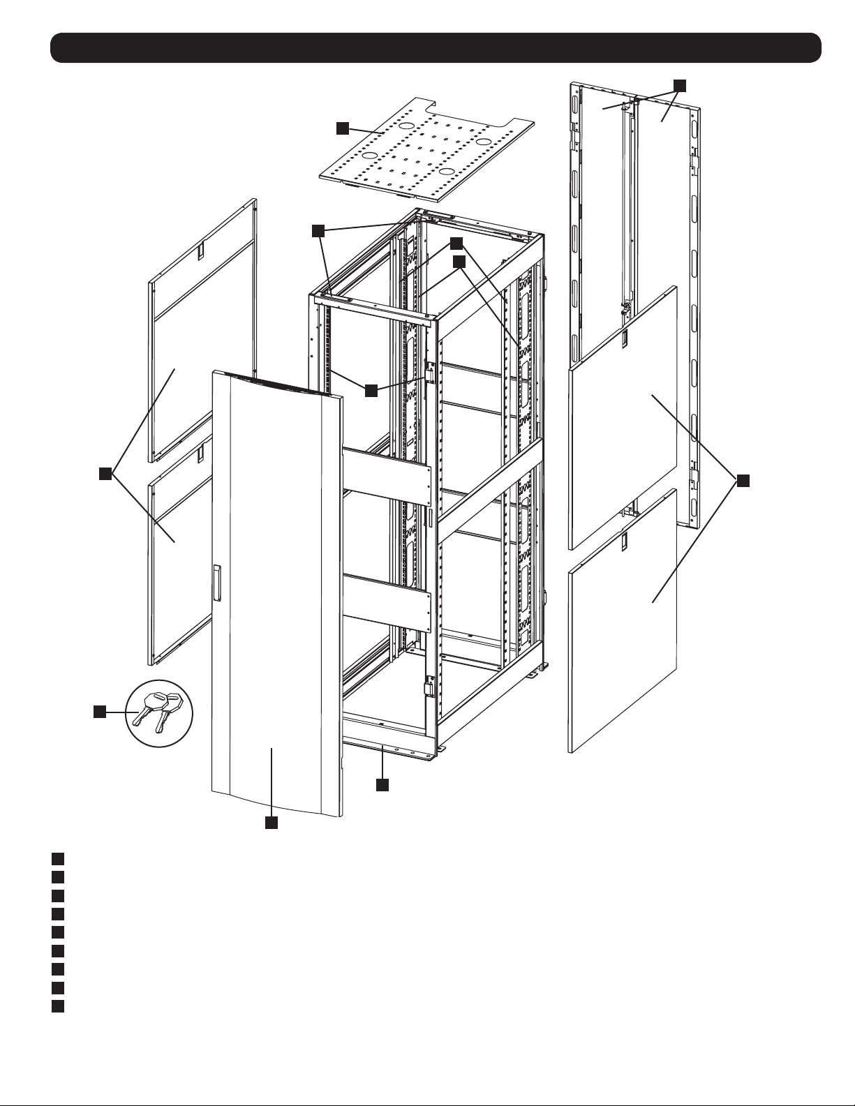
Feature Identification
1
Roof Panel
2
Locking Split Rear Doors
3
Locking Side Panels
4
Cable Management Rails
5
Zone 4 Seismic Brackets
6
Mounting Rails (Provide horizontal and vertical mounting points for equipment.)
7
Keys (One for the doors and one for the side panels.)
8
Locking Reversible Front Door
9
Baying Brackets
Not Shown: Mounting hardware, documentation and other shipping materials.
1
2
7
4
6
5
8
3
3
6
9

4
Enclosure Installation
Caution! Read All Instructions and Warnings Before Installation!
WARNING: The rack enclosure is extremely heavy. Do not attempt to unpack, move or install the enclosure without assistance.
Until it has been properly installed and stabilized, the enclosure is prone to tipping and could cause property damage and/or
personal injury. Use extreme caution when handling the enclosure and be sure to follow all handling and installation instructions.
Do not attempt to install equipment without first stabilizing the enclosure.
Preparation
The enclosure must be installed in a structurally sound area with a level floor that is able to bear the weight of the enclosure, all the equipment that
will be installed in the enclosure, and any other enclosures and/or equipment that will be installed nearby. Before unpacking the enclosure, you should
transport the shipping container closer to the final installation location to minimize the distance you will need to move the unit after the protective
packaging has been removed. If you plan to store the enclosure for an extended period before installation, follow the instructions in the Storage and
Service section.
Unpacking
NOTE: The enclosure should be moved as close to the desired installation location as possible before it is unpacked from the
shipping container. Use a forklift or pallet jack to move the shipping container.
You need several tools (user-supplied):
• 13 mm Open-end Wrench
• Utility Blade
• Carpenter's Level
• Phillips-head Screwdriver
You also need the following hardware (included):
• (50) Phillips-head Mounting Screws (M6 x 5/8")
• (50) Cage Nuts (M6)
• (50) Nylon Cup Washers
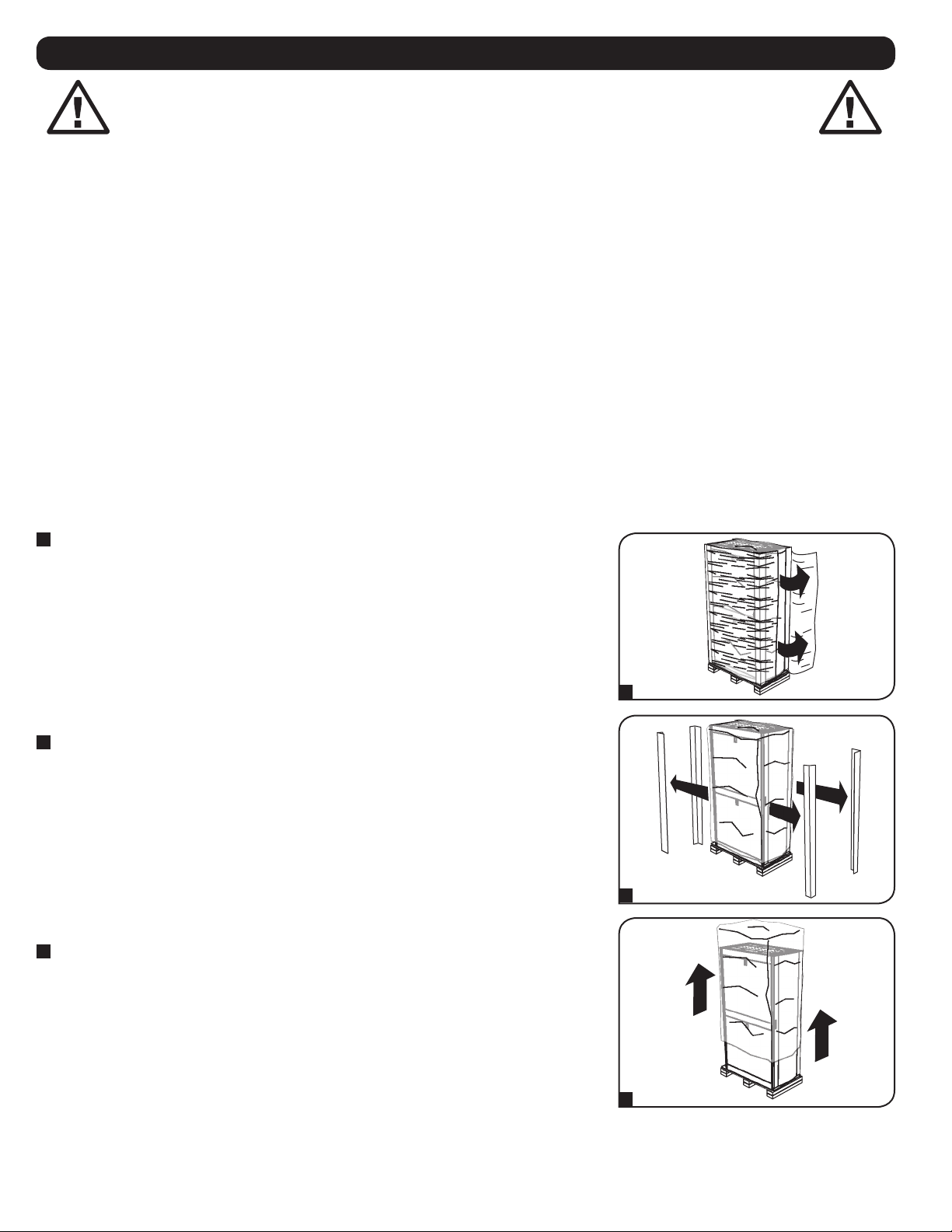
1
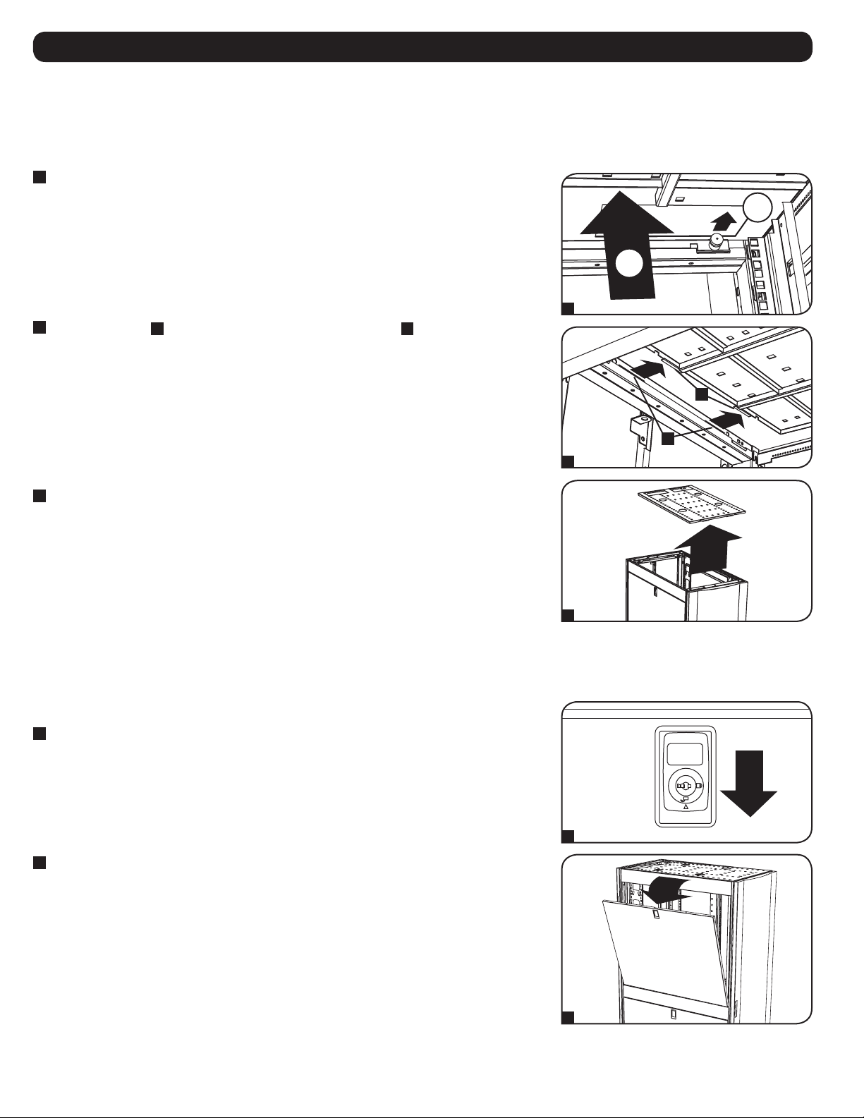
Confirm that the shipping container is upright and stable, then use a utility blade to cut the
shrink-wrap securing the corner protectors. Apply the utility blade directly over the corner
protectors to prevent the utility blade from scratching the enclosure or cutting the protective
heavy plastic bag beneath the shrink-wrap. WARNING: Do not scratch the enclosure or
cut the heavy plastic bag beneath the shrink-wrap. Do not push or pull the
enclosure while unpacking.
2
Remove the corner protectors. Save all packing materials (including the pallet) for later use
unless you are certain they will not be required. The packing materials are recyclable.
3
Remove the heavy plastic bag surrounding the enclosure. Examine the enclosure for any
damage or loose parts. Confirm that all parts are present. If anything is missing or damaged,
contact Tripp Lite for assistance. Do not attempt to use the enclosure if it has been damaged.
1
2
3

5
Enclosure Installation
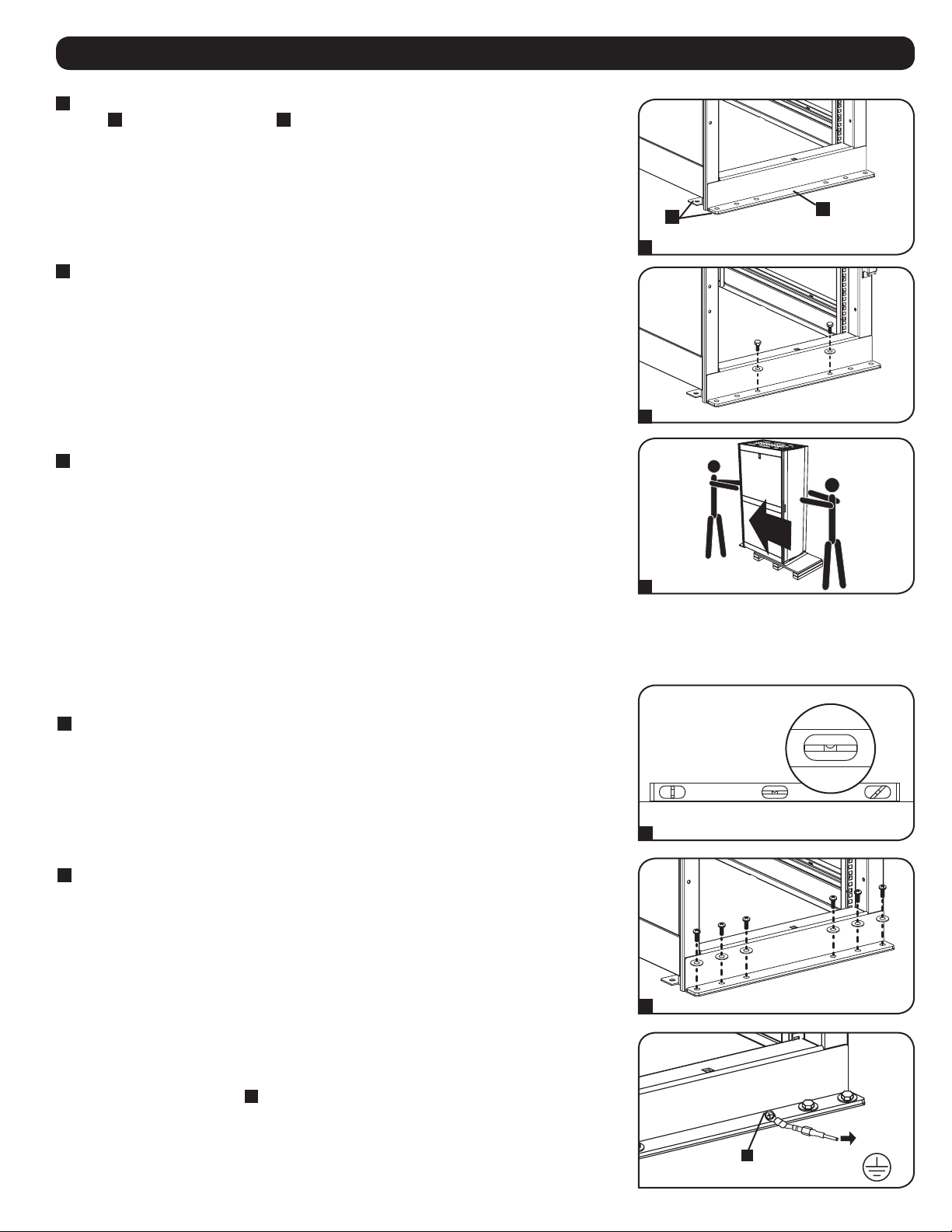
4
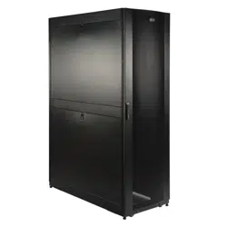
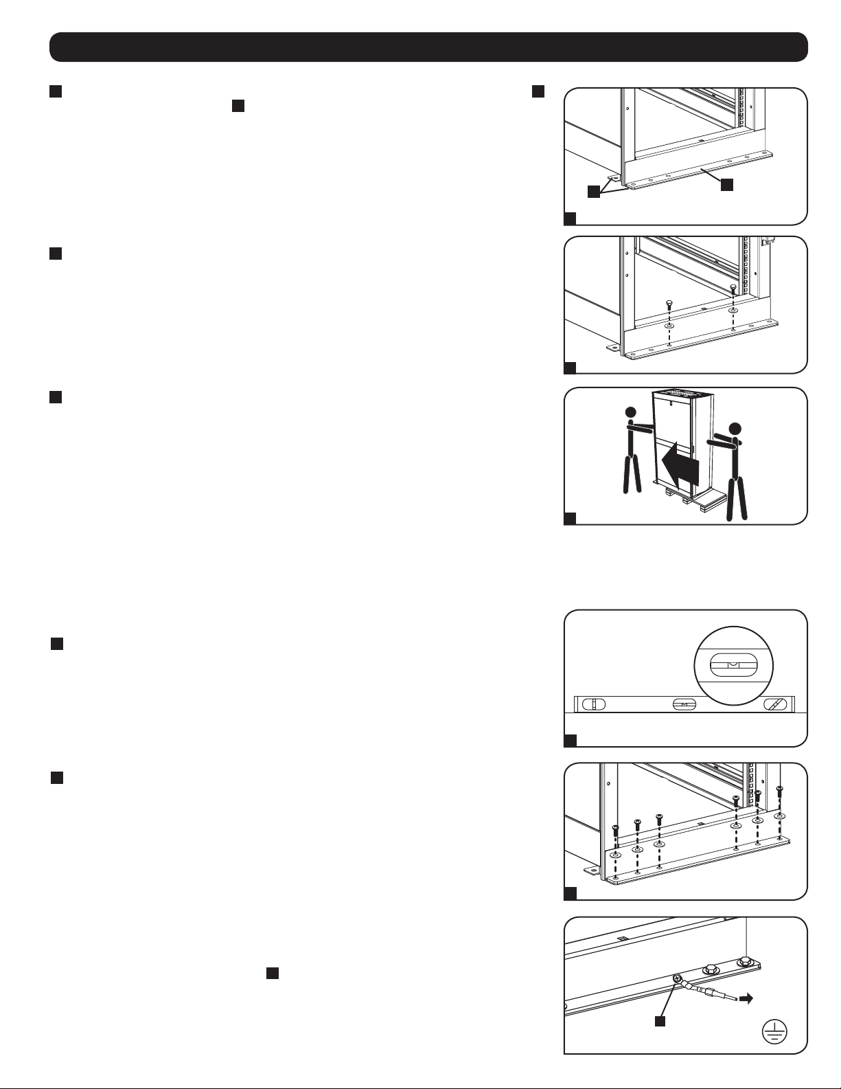
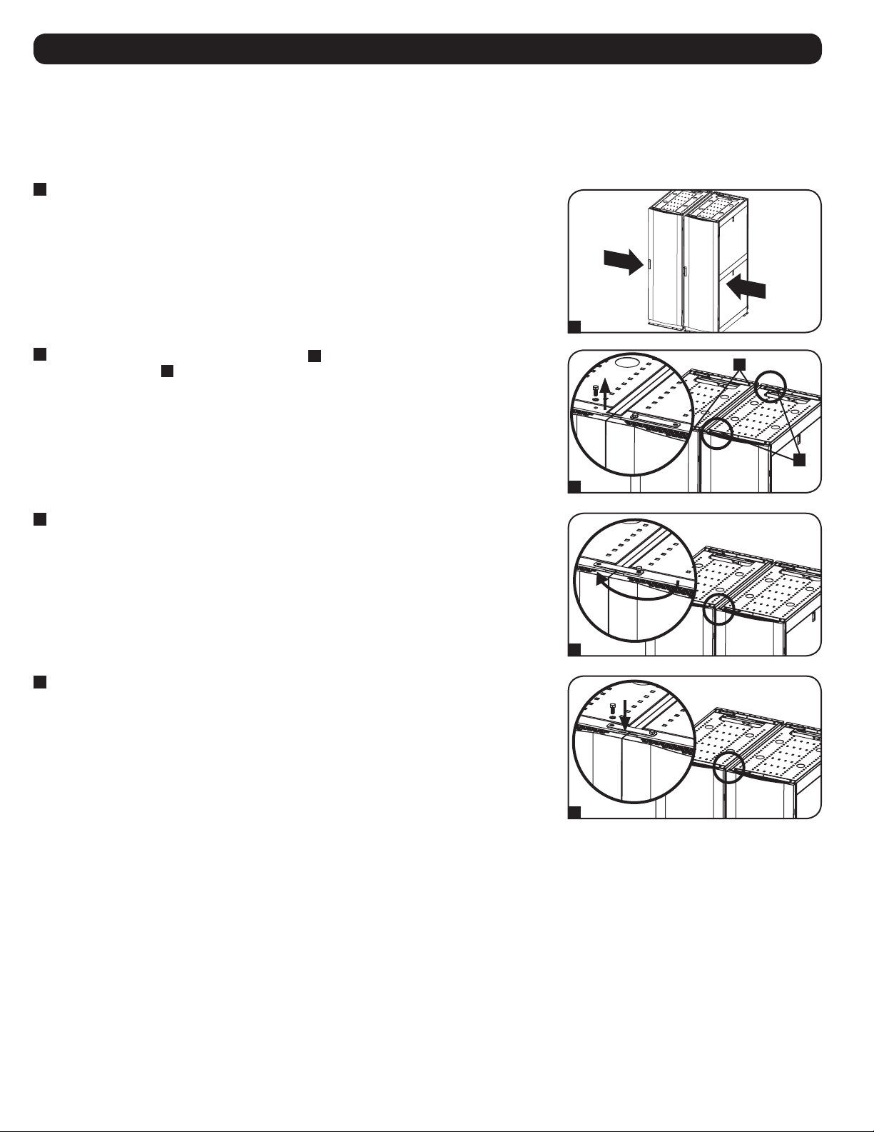
Use the key to open the enclosure's doors and locate the base Zone 4 Seismic Brackets
A
and
reinforcing brackets
B
that are bolted into the shipping pallet. Note: The keys are shipped in
the accessory carton that comes attached to the side panel carton.
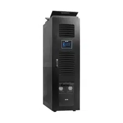
5
Use a 13 mm open-end wrench to remove the bolts attaching the enclosure to the shipping
pallet. Be extremely careful, as the enclosure could shift unexpectedly after bolt removal. Save
the reinforcing brackets and bracket hardware for later use.
6
Position at least one person at the front of the enclosure and one person at the rear of the
enclosure. Carefully lift the enclosure from the pallet and place it in the desired location.
WARNING: Use at least one assistant when removing the enclosure from the pallet.
Be extremely careful when moving the enclosure.
If required, the enclosure can be lifted by attaching 4 user-supplied M8 diameter eye bolts to the
threaded holes near the upper corners of the enclosure frame. Use steel bolts with an ISO strength
rating of 8.8 or higher. The 4 bolts can support the weight of the enclosure and up to 1000 lbs
(450 kg) of installed equipment. WARNING: Only experienced equipment operators should
attempt to lift the enclosure. Use appropriate equipment and follow all applicable
safety procedures and regulations.
Placement
Note: Proper anchoring hardware should already be in place before starting this procedure.
1
Use a carpenter’s level to check the slope of the floor in the desired location. If the floor slopes
more than 1%, choose an alternate installation site.
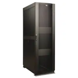
2
In order to secure the cabinet to the building structure for stability, use M8 hardware (user-
supplied) to secure the base of the enclosure and the Zone 4 Seismic Brackets into pre-
installed anchoring hardware in the floor. Tighten the hardware using a torque wrench.
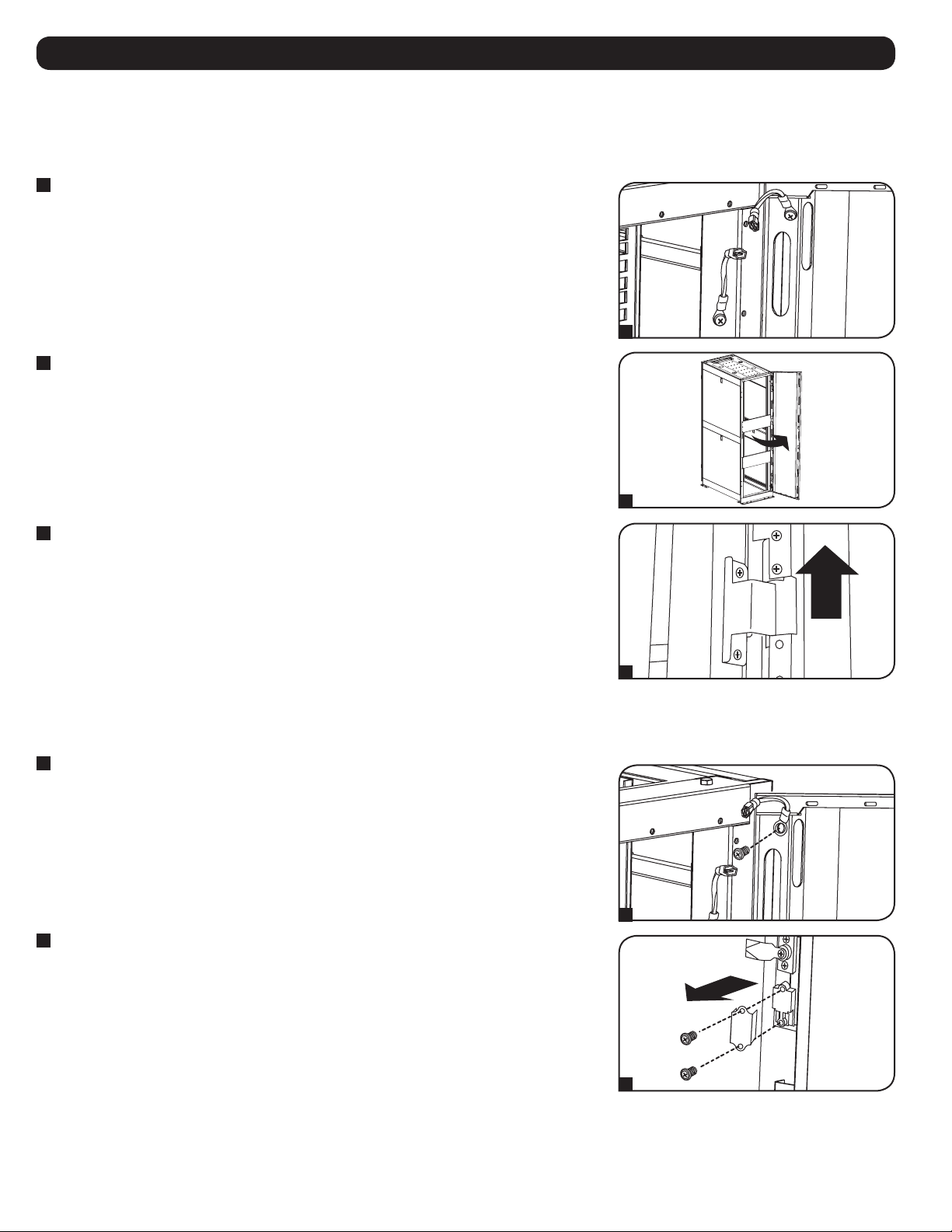
Ground Connection
All the parts of the enclosure are grounded to the frame of the enclosure. Connect the frame of the
enclosure directly to your facility's earth ground connection using an 8 AWG (3.264 mm) wire and
one of the pieces of hardware
A
used to secure the enclosure to the floor
. Remove one of the
pieces of hardware to connect the grounding wire and then re-fasten the hardware to secure the
connection. WARNING: Attach each enclosure to earth ground separately. Do not use
the enclosure without an earth ground connection.
1
2
4
5
6
FLOOR
EARTH
GROUND
A
B
A
6
Enclosure Configuration
Adding or Removing Front and Rear Doors
WARNING: Do not attempt to add or remove doors without assistance.
Removing Door
1
Disconnect the door's ground wire.
2
Open the door until it is perpendicular (90 degrees) to the front of the enclosure.
3
Lift the door from the hinges and remove it from the enclosure.
To Reinstall Door, Reverse Steps 1-3.
(Optional) If the enclosure is joined to another enclosure, turn the door back toward the enclosure
as you lift it from the hinges.
Reversing Front Door
WARNING: Do not attempt to reverse the front door without assistance.
1
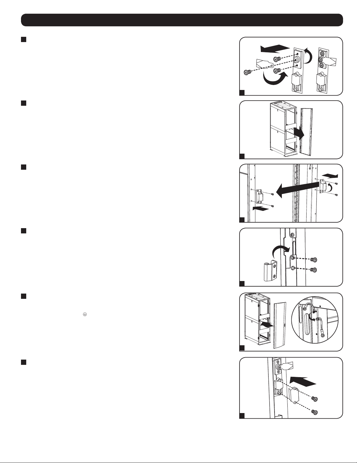
Remove the screw connecting the ground wire to the inside of the door.
2
Remove the 2 screws connecting the door handle to the door. Remove the door handle.
90°
1
1
2
2
3

7
Enclosure Configuration
3
Remove the screw and washer from the rear of the door handle and remove the latching
mechanism. Rotate the latch washer counter-clockwise 90 degrees and reverse the latch so it
points in the opposite direction, then use the screw and washer to re-attach the latch to the
rear of the door handle.
4
Remove the door by following the steps in the previous section.
5
Remove the door hinges from the enclosure, rotate them 180 degrees and attach them on the
opposite side of the enclosure. Note: The alternate door hinge attachment points have plastic
plugs in the screw holes. Remove the plugs and insert them in the original door hinge
attachment points.
6
Unscrew the 2 hinge mechanisms from the hinge openings inside the door, then reattach each
of them using the set of screw holes immediately opposite their original position.
7
Rotate the door 180 degrees and reinstall it on the enclosure. Remember to connect the
ground wire to the inside of the door, using the attachment point nearest the hinge at the top of
the door. The attachment point is marked with the ground connection symbol: .
8
Reinstall the door handle.
3
6
4
7
5
8

8
Adding or Removing Roof Panel
WARNING: Do not attempt to use the roof panel for weight-bearing purposes other than those explicitly described and approved by
Tripp Lite. Do not attempt to add or remove the roof panel without assistance.
Enclosure Configuration
Adding or Removing Side Panels
Removing Side Panel
1
Open the latch by sliding it downward.
2
Tilt the top of the panel away from the enclosure.
Removing Roof Panel
1
Pull the 2 pins near the rear of the roof panel. While holding the pins, push the roof panel
upward.
2
Remove the roof panel tabs
A
from the roof panel attachment slots
B
in the enclosure frame.
3
Lift the roof panel from the enclosure.
To Reinstall Roof Panel, Reverse Steps 1-3.
2
1
1
2
B
A
3
1
2

9
Enclosure Configuration
Adjusting Mounting Rails and Cable Management Rails
WARNING: Do not attempt to adjust rails without assistance. Do not attempt to adjust rails while equipment is installed in the
enclosure. Do not attempt to use rails without screws installed (6 per rail).
The 4 mounting rails are pre-installed to accommodate equipment with a mounting depth of 30 inches (762 mm). Do not adjust the mounting rails
unless your equipment requires a different mounting depth. The front and rear sets of rails can be adjusted independently in ¼-inch (6 mm)
increments for mounting depths between 4 inches (101.6 mm) and 42 inches (1066.8 mm).
3
Lift the panel away from the brace that supports it.
To Reinstall Side Panel, Reverse Steps 1-3.
1
Each rail is connected to the enclosure with 6 screws: 1 pair at the upper beam
A
, 1 pair at
the middle beam
B
and 1 pair at the lower beam
C
.
2
Remove the screws fastening each of the rear mounting rails to the enclosure. (If adjustment of
the front rails is required, you can also remove the screws from the front rails.)
3
Slide the mounting rails to the desired depth and reattach them using the screws you removed
in Step 2. The rail attachment points are numbered
A
to help you align each pair of rails at the
same depth.
The depth of the 2 cable management rails can be adjusted using the
same method.
4 5 6 3 4 5 6 7 8 9 0 1 2
3
8
6 7 8 9 0 1 2 3 4
5 6 0 1 2 3
5
3
1
2
3
A
A
B
C

10
Enclosure Configuration
2
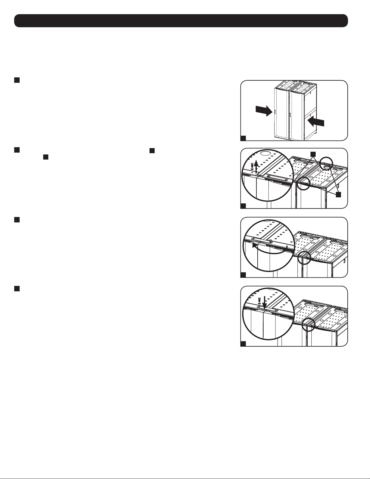
Each enclosure includes 2 baying brackets
A
that correspond to baying connection points
B
on the adjoining enclosure. The baying connection points already contain bolts. Remove the bolt
and washer from each baying connection point in the adjoining enclosure.
3
Loosen the bolt in each baying bracket and turn each bracket 180 degrees toward the adjoining
enclosure, aligning each bracket with the corresponding baying connection point on the
adjoining enclosure.
4
Connect each bracket to the adjoining enclosure using the bolts and washers you removed in
step 2, but do not tighten the bolts completely. Adjust the position of the enclosures as needed.
After connecting all brackets and confirming that the enclosures do not need further
adjustment, tighten all bolts.
Note: You may wish to remove the doors from the enclosures before combining them. Reinstalling
the doors afterward is optional. Remove the interior side panels before baying enclosures if you
wish to enable access between enclosures.
Combining (Baying) Enclosures
WARNING: Combining enclosures is not a substitute for stabilizing the enclosures. Each enclosure in a bay of combined enclosures
requires the same stabilizing measures as a standalone enclosure.
Note: This baying method is specifically for joining SR42UBZ4 enclosures together. Other models have different baying methods. Consult the
appropriate model’s manual.
1
Arrange the enclosures in the correct position for baying.
2
3
4
A
B
180°
1

11
Equipment Installation
WARNING: Do not install equipment until you have stabilized the enclosure. Install heavier equipment first and install it toward the
bottom of the enclosure. Install equipment starting from the bottom of the enclosure and proceeding toward the top of the
enclosure, never the reverse. If using sliding equipment rails, be careful when extending the rails. Do not extend more than one
set of sliding equipment rails at one time. Avoid extending sliding equipment rails near the top of the enclosure.
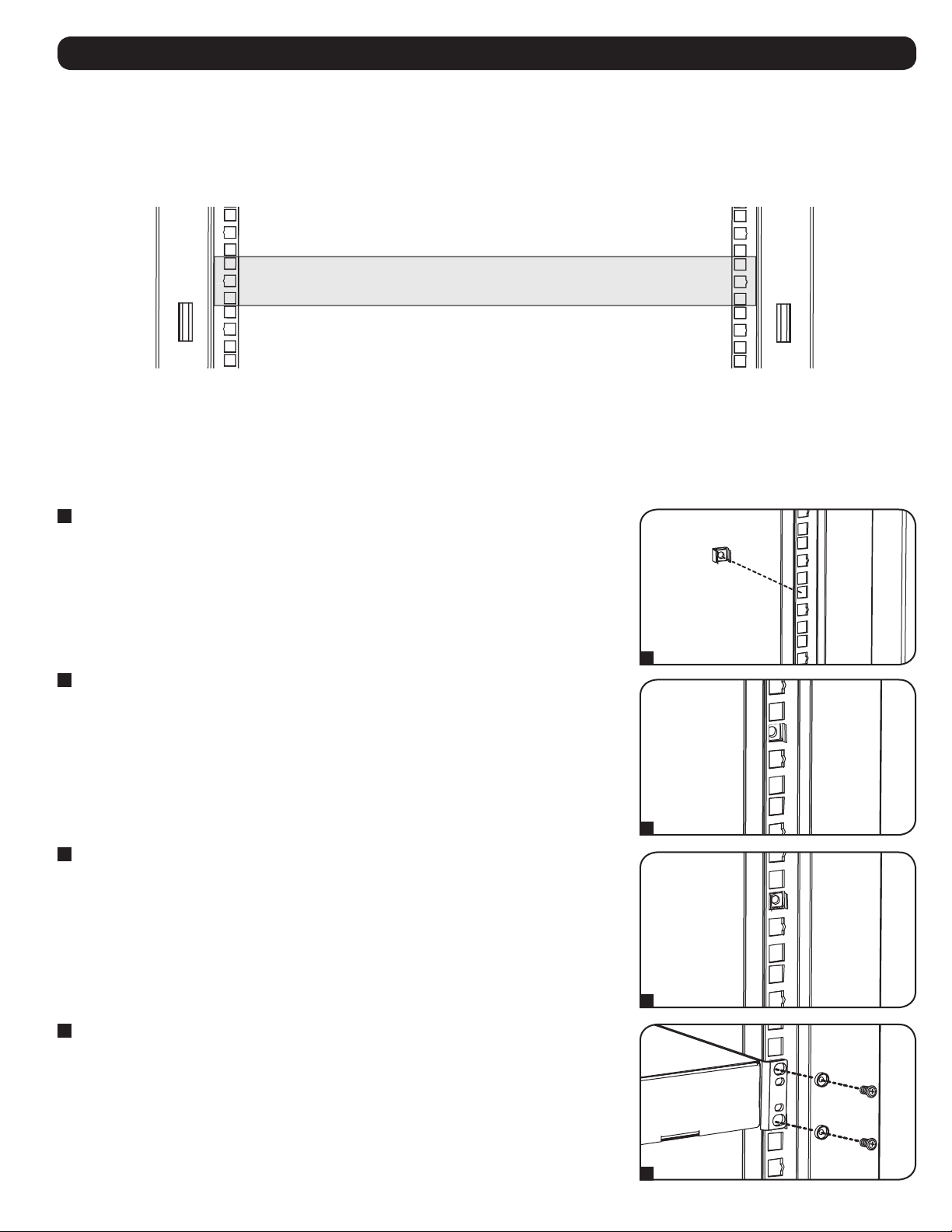
Note: The square holes at the middle of each rack unit are numbered and also include a small notch to aid identification. A single rack unit includes
the space occupied by the numbered hole and the holes directly above and below.
Installing or Removing Cage Nuts
WARNING: The flanges of the cage nuts should engage the sides of the square opening in the rail, not the top and bottom. Follow
the instructions in your equipment documentation to ensure proper installation of your equipment.
Installing Cage Nuts
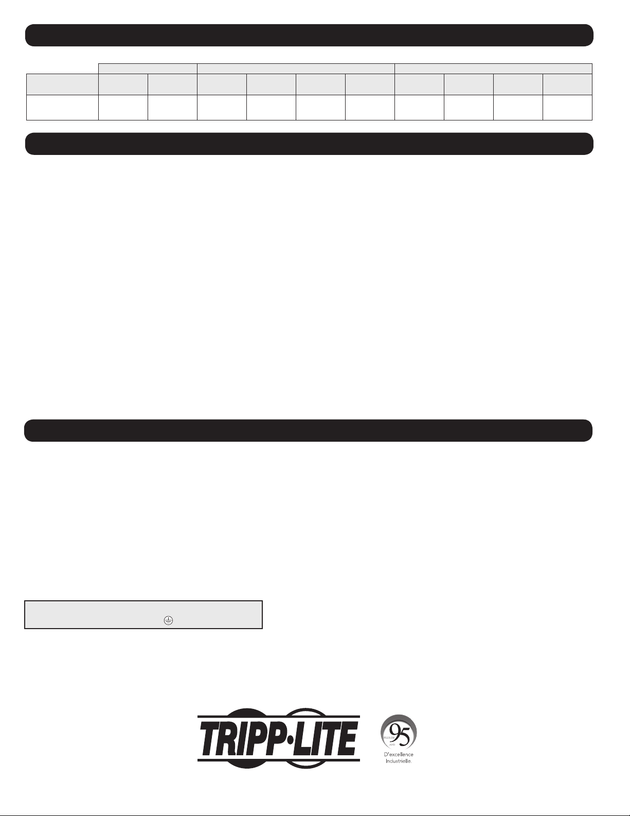
1
Locate the numbered square openings in the mounting rails where you plan to install your
equipment. You will install cage nuts (included) into the square openings in order to provide an
attachment point for the mounting screws (included). Note: Consult your equipment
documentation to determine how many cage nuts will be required and where they will need to
be installed.
2
From the inside of the mounting rail, insert one of the flanges of the cage nut through the
square opening. Press it against the side of the square opening. Each flange should engage one
side of the square opening, not the top or bottom.
3
Compress the cage nut at the sides slightly to allow the remaining flange to fit through the
square opening. When the cage nut is properly installed, both flanges will protrude through the
square opening and will be visible on the outer surface of the mounting rail. Repeat steps 1-3
until all required cage nuts are installed.
4
After installing the required cage nuts, use the included mounting screws and cup washers to
secure your equipment to the rack rail. Place the cup washers between the screws and the
equipment mounting brackets. Note: Your equipment may also include mounting hardware.
Read the mounting instructions that came with your equipment before installing your
equipment.
To Remove Cage Nuts, Reverse Steps 1-3.
Note: You may wish to use a cage nut tool (user-supplied) to aid in cage nut installation and
removal.
24
25
23
24
25
23
24
24
2
1 Rack Unit
20
19
22
21
20
19
21
20
19
21
20
19
21
1
2
3
4
12
1111 W. 35th Street, Chicago, IL 60609 USA • www.tripplite.com/support
Specifications
Load Rating Unit Dimensions Shipping Dimensions
Model Static Rolling Height Width Depth Weight Height Width Depth Weight
SR42UBZ4
3000 lb
(1361 kg)
2250 lb
(1021 kg)
78.5 in
(1994 mm)
23.63 in
(600 mm)
43 in
(1093 mm)
353 lb
(161 kg)
85 in
(2159 mm)
26 in
(661 mm)
45 in
(1143 mm)
395 lb
(179 kg)
Storage and Service
Storage
The enclosure should be stored in a controlled indoor environment, away from moisture, temperature extremes, flammable liquids and gasses,
conductive contaminants, dust and direct sunlight. Store the enclosure in its original shipping container if possible.
Service
Your Tripp Lite product is covered by the warranty described in this manual. A variety of Extended Warranty and On-Site Service Programs are also
available from Tripp Lite. For more information on service, visit www.tripplite.com/support. Before returning your product for service, follow these steps:
1. Review the installation and operation procedures in this manual to ensure that the service problem does not originate from a misreading of the
instructions.
2. If the problem continues, do not contact or return the product to the dealer. Instead, visit www.tripplite.com/support.
3. If the problem requires service, visit www.tripplite.com/support and click the Product Returns link. From here you can request a Returned Material
Authorization (RMA) number, which is required for service. This simple on-line form will ask for your unit’s model and serial numbers, along with
other general purchaser information. The RMA number, along with shipping instructions, will be emailed to you. Any damages (direct, indirect,
special or consequential) to the product incurred during shipment to Tripp Lite or an authorized Tripp Lite service center is not covered under
warranty. Products shipped to Tripp Lite or an authorized Tripp Lite service center must have transportation charges prepaid. Mark the RMA number
on the outside of the package. If the product is within its warranty period, enclose a copy of your sales receipt. Return the product for service using
an insured carrier to the address given to you when you request the RMA.
Warranty and Product Registration
5-Year Limited Warranty
Seller warrants this product, if used in accordance with all applicable instructions, to be free from original defects in material and workmanship for a period of 5 years from the date of
initial purchase. If the product should prove defective in material or workmanship within that period, Seller will repair or replace the product, in its sole discretion.
THIS WARRANTY DOES NOT APPLY TO NORMAL WEAR OR TO DAMAGE RESULTING FROM ACCIDENT, MISUSE, ABUSE OR NEGLECT. SELLER MAKES NO EXPRESS WARRANTIES OTHER
THAN THE WARRANTY EXPRESSLY SET FORTH HEREIN. EXCEPT TO THE EXTENT PROHIBITED BY APPLICABLE LAW, ALL IMPLIED WARRANTIES, INCLUDING ALL WARRANTIES OF
MERCHANTABILITY OR FITNESS, ARE LIMITED IN DURATION TO THE WARRANTY PERIOD SET FORTH ABOVE; AND THIS WARRANTY EXPRESSLY EXCLUDES ALL INCIDENTAL AND
CONSEQUENTIAL DAMAGES. (Some states do not allow limitations on how long an implied warranty lasts, and some states do not allow the exclusion or limitation of incidental or
consequential damages, so the above limitations or exclusions may not apply to you. This warranty gives you specific legal rights, and you may have other rights which vary from
jurisdiction to jurisdiction).
WARNING: The individual user should take care to determine prior to use whether this device is suitable, adequate or safe for the use intended. Since individual applications are
subject to great variation, the manufacturer makes no representation or warranty as to the suitability or fitness of these devices for any specific application.
Product Registration
Visit www.tripplite.com/warranty today to register your new Tripp Lite product. You'll be automatically entered into a drawing for a chance to win a FREE Tripp Lite product!*
* No purchase necessary. Void where prohibited. Some restrictions apply. See Web site for details.
Tripp Lite has a policy of continuous improvement. Product specifications are subject to change without notice.
Note on Labeling
This symbol is used on the product: Ground Connection
19-02-238 93-3065_revC

13
Gabinete SmartRack
®
con Especificación Sísmica de Zona 4
Modelo: SR42UBZ4
(Número de Serie: AGAC7761)
Manual del Propietario
Instrucciones de seguridad importantes 14
Descripción General 14
Identificación de Características 15
Instalación del Gabinete 16
Preparación 16
Desempacado 16
Colocación 17
Conexión a Tierra 17
Configuración del Gabinete 18
Colocación o Remoción de las Puertas Delanteras y 18
Traseras
Inversión de la Puerta Delantera 18
Colocación o Remoción del Panel de Techo 20
Colocación o Remoción de los Paneles Laterales 20
Ajuste de los Rieles de Instalación y Rieles de 21
Administración de Cables
Combinación de Gabinetes (Instalación en Hileras) 22
Instalación del Equipo 23
Instalación o Remoción de Tuercas de Fijación 23
Especificaciones 24
Almacenamiento y Servicio 24
Garantía 24
English 1
Francés 25
Русский
37
1111 W. 35th Street, Chicago, IL 60609 EE UU • www.tripplite.com/support
Copyright © 2019 Tripp Lite. Todos los derechos reservados. Todas las marcas registradas son propiedad de sus respectivos propietarios.

14
Instrucciones de Seguridad Importantes
CONSERVE ESTAS INSTRUCCIONES
Todas las secciones de este manual contienen instrucciones y advertencias que deben observarse durante la instalación y uso de los Gabinetes
SmartRack aquí descritos. Lea cuidadosamente todas las instrucciones y advertencias antes de intentar mover, instalar o utilizar los Gabinetes
SmartRack descritos en este manual. El incumplimiento creará un riesgo de lesiones personales y daños a la propiedad y puede invalidar la
garantía.
• Mantenga el gabinete en un ambiente interior controlado lejos de humedad excesiva, temperaturas extremas, líquidos y gases inflamables,
contaminantes conductores, polvo o luz solar directa.
• Deje un espacio adecuado en la parte delantera y trasera del gabinete para una ventilación adecuada. No bloquee, cubra ni coloque objetos en las
aberturas externas de ventilación del gabinete.
• El gabinete es extremadamente pesado. Tenga cuidado al manejar el gabinete. No intente desempacarlo, moverlo o instalarlo sin ayuda. Utilizar un
dispositivo mecánico como un montacargas o gato para tarimas para mover el gabinete en el contenedor de embarque.
• No coloque objeto alguno sobre el gabinete, especialmente recipientes de líquidos y no intente apilar los gabinetes.
• Inspeccione el contenedor de embarque y el gabinete para detectar daños durante el envío. No use el gabinete si está dañado.
• Deje el gabinete en el contenedor de embarque hasta que haya sido movido tan cerca a su ubicación final como sea posible.
• Instale el gabinete en un área estructuralmente firme con un piso nivelado que pueda soportar la carga del peso del gabinete, de todo el equipo
que se instale en el gabinete y otros gabinetes y otros equipos que se instalen cerca.
• Instale firmemente el gabinete a la estructura del edificio, usando los soportes de embarque como se ilustra en la sección de Instalación del
Gabinete de este manual.
• No empuje el gabinete de sus paneles laterales para moverlo. Empujarlo de sus paneles laterales creará un peligro de vuelco.
• Tenga cuidado cuando corte el material de empaque. El gabinete podría haber sido rasguñado o rayado, causando daños no cubiertos por la
garantía.
• Guarde todo el material de empaque para uso posterior. Volver a empacar y enviar el gabinete sin el material de empaque original puede ocasionar
daños al producto que anularían la garantía.
• No reembarque el gabinete con equipo adicional a menos que el gabinete haya sido embarcado con una tarima especial anti-impacto (solo
modelos “SP1”). El peso combinado del gabinete y el equipo instalado no debe exceder la capacidad de carga de la tarima. Tripp Lite no es
responsable por cualquier daño que se produzca durante el reenvío.
• No se recomienda el uso de este equipo en aplicaciones de soporte de vida en donde razonablemente se pueda esperar que la falla de este equipo
cause la falla del equipo de soporte de vida o afectar significativamente su seguridad o efectividad.
Descripción General
Los Gabinetes SmartRack acomodan todos los equipos para instalación en rack estándar de 19", sin importar el proveedor y se embarcan
completamente ensamblados para una instalación rápida y fácil. Cuentan con gabinetes adaptables de servicio pesado con profundidades de
instalación variables, lo que las hace ideales para servidores. Para comodidad en el mantenimiento, los gabinetes incluyen puertas y paneles laterales
de rápida liberación. El hardware integrado para anclar y unir los gabinetes permite la expansión ordenada, eficiente y rentable. Las puertas frontal,
posterior y los paneles laterales pueden cerrarse con cerradura
El SR42UBZ4 está diseñado para uso en zonas sísmicas. El gabinete cuenta con una construcción soldada, proporcionando más seguridad para uso
en entornos inestables. Los Soportes Sísmicos de Refuerzo para Zona 4 ofrecen estabilidad y protección mejoradas con una especificación para Zona
Sísmica 4.
15
Identificación de Características
1
Panel de Techo
2
Puertas Posteriores Divididas con Cerradura
3
Paneles Laterales con Cerradura
4
Rieles para Manejo del Cableado
5
Soportes Sísmicos para Zona 4
6
Rieles de Instalación (Proporcionan puntos de instalación horizontal y vertical para los equipos.)
7
Llaves (Una para las puertas y una para los paneles laterales).
8
Puerta Frontal Reversible con Cerradura
9
Soportes de Fijación para Colocación en Hieras
No se Muestra: Accesorios de instalación, documentación y otros materiales de embarque.
1
2
7
4
6
5
8
3
3
6
9
16
Instalación del Gabinete
¡Precaución! ¡Lea todas las instrucciones y las
advertencias antes de realizar la instalación!
ADVERTENCIA: El gabinete es extremadamente pesado. No intente desempacar, mover o instalar el gabinete sin asistencia. Hasta que haya sido correctamente
instalado y estabilizado, el gabinete es propenso a vuelcos y podría causar daños a la propiedad y/o lesiones personales. Tenga mucho cuidado al manipular el
gabinete y asegúrese de seguir todas las instrucciones de manejo e instalación. No intente instalar equipo sin estabilizar primero el gabinete.
Preparación
El gabinete debe instalarse en un área estructuralmente firme con un piso nivelado, que pueda soportar la carga del peso del gabinete, de todo el
equipo que se instale en el gabinete, otros gabinetes y otros equipos que se instalen cerca. Antes de desempacar el gabinete, debe transportar el
contenedor de embarque lo más cerca posible a la posición de instalación final para minimizar la distancia que necesite mover la unidad después de
haber retirado el empaque protector. Si va a almacenar el gabinete durante un largo período antes de la instalación, siga las instrucciones en la
sección de Almacenamiento y Servicio.
Desempacado
NOTA: El gabinete debe ser trasladado tan cerca de la ubicación de instalación que desee posible antes de desempacarlo del
contenedor de embarque. Utilice un montacargas o gato para tarimas para mover el contenedor de embarque.
Se necesitan varias herramientas (suministrados por el usuario):
• Llave Española de 13 mm
• Cuchilla
• Nivel de Carpintero
• Desatornillador Phillips
Además necesita los siguientes accesorios (incluidos):
• (50) Tornillos Cabeza Phillips para Instalación (M6 x 5/8")
• (50) Tuercas de Fijación (M6)
• (50) Arandelas de Copa de Nylon
1
Confirme que el contenedor de embarque esté vertical y estable, a continuación, utilice una
cuchilla para cortar la envoltura contráctil asegurando los protectores esquineros. Coloque la
cuchilla de utilidad directamente sobre uno de los protectores esquineros para evitar que la
cuchilla raye el gabinete o corte la pesada bolsa de plástico protectora debajo de la envoltura
retráctil. ADVERTENCIA: No raye el gabinete ni corte la pesada bolsa de plástico
debajo de la película contráctil. No empuje ni jale el gabinete durante el
desempaque.
2
Retire los esquineros protectores. Guarde todos los materiales de empaque (incluyendo la
tarima) para uso posterior a menos que esté seguro de que no los necesitará. Los materiales
de empaque son reciclables.
3
Retire la bolsa de plástico pesado que envuelve al gabinete. Examine el gabinete para detectar
cualquier daño o parte suelta. Confirme que están todas las partes. Si falta algo o está dañado,
póngase en contacto con Tripp Lite para obtener ayuda. No intente usar el gabinete si ha sido
dañado.
1
2
3
17
Instalación del Gabinete
4
Use la llave para abrir las puertas del rack y localizar los soportes para Zona Sísmica 4 de la
base
A
y los soportes de refuerzo
B
que están atornillados a la tarima de embarque. Nota:
Las llaves se envían en la caja que se adjunta a la caja del panel lateral.
5
Use una llave española de 13 mm para retirar los tornillos que sujetan el gabinete a la tarima
de embarque. Sea extremadamente cuidadoso, ya que el gabinete podría volcar
inesperadamente después de retirar el tornillo. Guarde los soportes de refuerzo y sus accesorios
para uso posterior.
6
Coloque al menos una persona en la parte delantera y otra en la parte posterior del gabinete.
Levante cuidadosamente el gabinete de la tarima y colóquelo en la ubicación deseada.
ADVERTENCIA: Use al menos un ayudante al retirar el gabinete de la tarima. Sea
extremadamente cuidadoso al desplazar el gabinete.
Si es necesario, el rack se puede levantar fijando 4 tornillos de argolla de diámetro M8 suministrados
por el usuario en los orificios roscados colocados cerca de los ángulos superiores del marco. Use
tornillos de acero con un grado de resistencia nominal ISO de 8.8 o mayor. Los 4 tornillos pueden
soportar el peso del gabinete y hasta 450 kg [1000 lb] de equipos instalados. ADVERTENCIA: Sólo
operadores de equipos experimentados deben intentar levantar el rack. Use los equipos
adecuados y siga todos los procedimientos y reglamentos de seguridad correspondientes.
Colocación
Nota: Los accesorios de anclaje adecuados ya deben estar en su lugar antes de comenzar este
procedimiento.
1
Utilice un nivel de burbuja para verificar la pendiente del piso en la ubicación deseada. Si el
piso tiene una pendiente mayor del 1%, elija un sitio alternativo de instalación.
2
Para asegurar el gabinete a la estructura del edificio para mayor estabilidad, utilice el
accesorios M8 (suministrados por el usuario) para asegurar la base del gabinete y los Soportes
Sísmicos de Zona 4 sobre el los accesorios de anclaje pre-instalados en el piso. Apriete los
accesorios utilizando una llave de torsión.
Conexión a Tierra
Todas las partes del gabinete se conectan a tierra con el bastidor del gabinete. Conecte el marco
del gabinete directamente a la conexión de tierra física de su instalación con un cable 8 AWG
(3.264 mm) y una de las piezas
A
usadas para asegurar el gabinete al piso
. Retire una de las
piezas que conecta el cable a tierra y luego vuelva a apretar el accesorio para asegurar la
conexión. ADVERTENCIA: Conecte a tierra cada gabinete por separado. No use el
gabinete sin una conexión a tierra física.
1
2
4
5
6
PISO
TIERRA
FÍSICA
A
B
A

18
Configuración del Gabinete
Colocación o Remoción de las Puertas Delanteras y Traseras
ADVERTENCIA: No intente colocar o remover las puertas sin ayuda.
Remoción de la Puerta
1
Desconecte el cable de conexión a tierra de la puerta.
2
Abra la puerta hasta que esté perpendicular (90 grados) con el frente del gabinete.
3
Levante la puerta de las bisagras y retírela del gabinete.
Para Reinstalar la Puerta, Invierta los Pasos 1 ~ 3.
(Opcional) Si el rack está unido a otro, gire la puerta hacia el gabinete mientras la levanta de las
bisagras.
Inversión de la Puerta Delantera
ADVERTENCIA: No intente invertir la puerta frontal sin ayuda.
1
Quite el tornillo que conecta el cable a tierra al interior de la puerta.
2
Quite los 2 tornillos que conectan la manija de la puerta a la puerta. Quite la manija de la
puerta.
90°
1
1
2
2
3

19
Configuración del Gabinete
3
Retire el tornillo y la arandela de la parte trasera de la manija de la puerta y retire el
mecanismo de enganche. Gire 90 grados la arandela de la cerradura en sentido contrario al
sentido de las manecillas del reloj e invierta el mecanismo de enganche para que apunte en la
dirección opuesta, a continuación, utilice el tornillo y la arandela para volver a colocar el
mecanismo de enganche a la parte posterior de la manija de la puerta.
4
Retire la puerta siguiendo los pasos de la sección anterior.
5
Quite las bisagras de la puerta, gírelas 180 grados y fíjelas del lado opuesto del gabinete. Nota:
Los puntos alternos para fijar las bisagras tienen pernos de plástico en los orificios para los
tornillos. Quítelos e insértelos en los puntos originales de fijación de las bisagras.
6
Desatornille los 2 mecanismos de bisagra de las aberturas de la bisagra dentro de la puerta y
fije cada uno de ellos utilizando el conjunto de orificios para tornillos directamente opuestos a
su posición original.
7
Rote la puerta 180 grados y vuelva a instalarla en el gabinete. Recuerde conectar el cable de
conexión a tierra al interior de la puerta usando el punto de fijación más cercano a la bisagra
en la parte superior de la puerta. El punto de fijación está marcado con el símbolo de conexión
a tierra: .
8
Vuelva a instalar la manija de la puerta.
3
6
4
7
5
8
20
Colocación o Remoción del Panel de Techo
ADVERTENCIA: No intente usar el panel de techo para soportar pesos que no sean los descritos explícitamente y aprobados por
Tripp Lite. No intente agregar o quitar el panel de techo sin ayuda.
Configuración del Gabinete
Para volver a instalar el Panel de Techo, Invierta los Pasos 1 ~ 3.
Colocación o Remoción de los Paneles Laterales
Remoción del Panel Lateral
1
Abra el pestillo deslizándolo hacia abajo.
2
Incline la parte superior del panel hacia afuera del gabinete.
Remoción del Panel de Techo
1
Jale las 2 clavijas cercanas a la parte trasera del panel de techo. Mientras las sostiene, empuje
el panel de techo hacia arriba.
2
Quite las pestañas
A
de las ranuras de fijación del panel de techo
B
en el marco del
gabinete.
3
Levante el panel de techo del gabinete.
2
1
1
2
B
A
3
1
2

21
Configuración del Gabinete
Rieles de Instalación con Ajuste y Rieles de Administración de Cables
ADVERTENCIA: No intente ajustar los rieles sin ayuda. No intente ajustar los rieles mientras el equipo está instalado en el
gabinete. No intente usar los rieles sin los tornillos instalados (6 por riel).
Los 4 rieles de instalación están preinstalados para acomodar equipo con una profundidad de instalación de 762 mm [30"]. No ajuste los rieles de
instalación a menos que su equipo requiera una profundidad de instalación diferente. Los juegos de rieles anterior y posterior pueden ajustarse
independientemente en incrementos de 6.35 mm [¼"] para instalación con profundidades entre 101.6 mm [4"] y 1066.8 mm [42"].
3
Levante el panel de la abrazadera que lo sostiene.
Para volver a instalar el Panel Lateral, Invierta los Pasos 1 ~ 3.
1
Cada riel está conectado al gabinete con los 6 tornillos: 1 par en la viga superior
A
, 1 par en
la viga media
B
y 1 par en la viga inferior
C
.
2
Retire los tornillos que sujetan cada uno de los rieles al gabinete. (Si se requiere el ajuste de
los rieles delanteros, puede también quitar los tornillos de los rieles delanteros).
3
Deslice los rieles de instalación a la profundidad deseada y vuélvalos a instalar usando los
tornillos que retiró en el Paso 2. Los puntos de sujeción del riel están numerados
A
para
ayudar a alinear cada par de rieles a la misma profundidad.
La profundidad de los 2 rieles de administración de cables se puede
ajustar utilizando el mismo método.
4 5 6 3 4 5 6 7 8 9 0 1 2
3
8
6 7 8 9 0 1 2 3 4
5 6 0 1 2 3
5
3
1
2
3
A
A
B
C
22
Configuración del Gabinete
2
Cada gabinete incluye 2 soportes para colocar en hileras
A
que corresponden a los puntos de
conexión
B
en el gabinete adyacente. Los puntos de conexión ya tienen tornillos. Retire el
tornillo y la arandela de cada punto de conexión en el gabinete adyacente.
3
Afloje el tornillo de cada soporte de conexión en fila y gire cada soporte a 180 grados hacia el
gabinete adyacente, alienando cada uno con el punto de conexión correspondiente en el
gabinete adyacente.
4
Conecte cada soporte al gabinete adyacente usando los tornillos y arandelas que quitó en el
paso 2, pero no apriete los tornillos por completo. Ajuste la posición de los gabinetes según
sea necesario. Después de conectar todos los soportes de fijación y de confirmar que los
gabinetes no necesitan más ajustes, apriete todos los tornillos.
Nota: Puede quitar las puertas de los gabinetes antes de combinarlos. Volver a instalarlas después
es opcional. Quite los paneles laterales interiores antes de fijar en hileras los gabinetes si desea
habilitar el acceso entre gabinetes.
Unión de Gabinetes (Instalación en Hileras)
ADVERTENCIA: Unir los racks en hileras de racks no sustituye su estabilización. Cada rack en una hilera necesita las mismas
medidas de estabilización que uno independiente.
Nota: Este método para colocar en hileras está especificado para unir los gabinetes SR42UBZ4 entre sí. Otros modelos tienen distintos métodos de
colocación en fila. Consulte el manual del modelo apropiado.
1
Disponga los gabinetes en la posición correcta para su colocación en fila.
2
3
4
A
B
180°
1

23
Instalación del Equipo
ADVERTENCIA: No instale el equipo hasta que haya estabilizado el gabinete. Instale primero los equipos más pesados e instálelos
hacia la parte inferior del gabinete. Instale los equipos a partir de la parte inferior del gabinete y proceda hacia la parte superior del
gabinete, nunca al revés. Si utiliza rieles de equipos deslizantes, tenga cuidado al extender los rieles. No extienda más de un juego
de rieles de equipos deslizantes a la vez. Evite extender los rieles de equipos deslizantes cerca de la parte superior del gabinete.
Nota: Los orificios cuadrados al centro de cada unidad de rack están numerados y también incluyen una pequeña muesca para ayudar a la
identificación. Una sola unidad de rack incluye el espacio ocupado por el orificio numerado y los orificios directamente arriba y abajo.
Instalación o Remoción de Tuercas de Fijación
ADVERTENCIA: Las bridas de las tuercas de fijación deben engarzar con los lados de la abertura del orificio cuadrado en el riel, no
en la parte superior o inferior. Siga las instrucciones en la documentación del equipo para asegurar una instalación adecuada de
su equipo.
Instalación de las Tuercas de Fijación
1
Localice los orificios cuadrados numerados en los rieles de instalación donde planea instalar su
equipo. Instalará tuercas de fijación (incluidas) en las aberturas cuadradas a fin de proporcionar
un punto de fijación para los tornillos de instalación (incluidos). Nota: Consulte la
documentación de su equipo para determinar cuántas tuercas de fijación requerirá y en dónde
necesitan instalarse.
2
Desde la parte interior del riel de instalación, inserte una de las bridas de la tuerca de fijación a
través de la abertura cuadrada. Presione contra el lado de la abertura cuadrada. Cada brida
debe engancharse en un lado de la abertura cuadrada, no en la parte superior o inferior.
3
Presione la tuerca de fijación ligeramente por los costados para permitir que el resto de la brida
se ajuste a través de la abertura cuadrada. Cuando la tuerca de fijación esté correctamente
instalada, ambas bridas sobresaldrán a través de la abertura cuadrada y serán visibles en la
superficie exterior del riel de instalación. Repita los pasos 1 ~ 3 hasta que estén instaladas
todas las tuercas de fijación requeridas.
4
Después de instalar las tuercas de fijación, use los tornillos de instalación y arandelas de
seguridad incluidos para fijar su equipo al riel del rack. Coloque las arandelas de seguridad
entre los tornillos y los soportes de instalación del equipo. Nota: Su equipo puede incluir
también accesorios para instalación. Lea las instrucciones de instalación que vienen con su
equipo antes de instalar su equipo.
Para Retirar las Tuercas de Fijación, Invierta los Pasos 1 ~ 3.
Nota: Usted puede desear usar una herramienta para tuerca de fijación (proporcionada por el
usuario) para ayudar en la instalación y desinstalación de la tuerca de fijación.
24
25
23
24
25
23
2
4
24
2
1 Unidad de Rack
20
19
22
21
20
19
21
20
19
21
20
19
21
1
2
3
4

24
1111 W. 35th Street, Chicago, IL 60609 EE UU • www.tripplite.com/support
Especificaciones
Capacidad de Carga Dimensiones de la Unidad Dimensiones de Envío
Modelo Estática En mov-
imiento
Altura Ancho Profundidad Peso Altura Ancho Profundidad Peso
SR42UBZ4
1361 kg
[3000 lb]
1021 kg
[2250 lb]
1994 mm
[78.5"]
600 mm
[23.63"]
1092 mm
[43"]
160 kg
[353 lb]
2159 mm
[85"]
661 mm
[26"]
1143 mm
[45"]
179 kg
[395 lb]
Almacenamiento y Servicio
Almacenamiento
El gabinete debe guardarse en un ambiente al interior controlado lejos de humedad excesiva, temperaturas extremas, líquidos y gases inflamables,
contaminantes conductores, polvo o luz solar directa. De ser posible, almacene el gabinete en su contenedor de embarque original.
Servicio
Su producto Tripp Lite está cubierto por la garantía descrita en este manual. Está disponible una variedad de Programas de Garantía Extendida y
Servicio En el Sitio por parte de Tripp Lite. Para información adicional acerca del servicio, visite www.tripplite.com/support. Antes de regresar su
producto para servicio, siga estos pasos:
1. Revise los procedimientos de instalación y operación en este manual para asegurar que el problema de servicio no se origina por una mala lectura
de las instrucciones.
2. Si el problema persiste, no se ponga en contacto ni regrese el producto al distribuidor. En vez de ello, visite www.tripplite.com/support.
3. Si el problema requiere servicio, visite www.tripplite.com/support y haga click en la liga Product Returns. Desde aquí usted puede solicitar un
número de Autorización de Devolución de Mercancía [RMA] que se requiere para servicio. Esta sencilla forma en línea le solicitará los números de
modelo y serie de su unidad junto con otra información general del comprador. El número de RMA junto con las instrucciones de embarque le serán
enviadas por correo electrónico. Cualquier daño (directo, indirecto, especial o consecuente) al producto incurrido durante el embarque a Tripp Lite o
un Centro de Servicio Autorizado de Tripp Lite no está cubierto bajo la garantía. Los productos embarcados a Tripp Lite o un Centro de Servicio
Autorizado de Tripp Lite deben tener cargos de transporte prepagados. Marque el número de RMA en el exterior del empaque. Si el producto está
dentro del período de garantía, adjunte una copia de su recibo de venta. Regrese el producto para servicio usando un transportista asegurado a la
dirección proporcionada a usted cuando solicitó la RMA.
Garantía
Garantía Limitada por 5 Años
El vendedor garantiza este producto, si se usa de acuerdo con todas las instrucciones aplicables, de que está libre de defectos en material y mano de obra por un período de 5 años
a partir de la fecha de compra inicial. Si el producto resultara defectuoso en material o mano de obra dentro de ese período, el vendedor reparará o reemplazará el producto a su
entera discreción.
ESTA GARANTÍA NO SE APLICA AL DESGASTE NORMAL O A LOS DAÑOS QUE RESULTEN DE ACCIDENTES, USO INCORRECTO, USO INDEBIDO O NEGLIGENCIA. EL VENDEDOR NO
OTORGA GARANTÍAS EXPRESAS DISTINTAS A LA ESTIPULADA EN EL PRESENTE. SALVO EN LA MEDIDA EN QUE LO PROHÍBAN LAS LEYES APLICABLES, TODAS LAS GARANTÍAS
IMPLÍCITAS, INCLUYENDO TODAS LAS GARANTÍAS DE COMERCIALIZACIÓN O IDONEIDAD, ESTÁN LIMITADAS EN DURACIÓN AL PERÍODO DE GARANTÍA ESTABLECIDO; ASIMISMO, ESTA
GARANTÍA EXCLUYE EXPRESAMENTE TODOS LOS DAÑOS INCIDENTALES E INDIRECTOS. (Algunos estados no permiten limitaciones en cuanto a la duración de una garantía y algunos
estados no permiten la exclusión o limitación de daños incidentales o indirectos, de modo que las limitaciones anteriores pueden no aplicar para usted. Esta garantía le otorga
derechos legales específicos y usted puede tener otros derechos que pueden variar de una jurisdicción a otra).
ADVERTENCIA: antes de usarlo, cada usuario debe tener cuidado al determinar si este dispositivo es adecuado o seguro para el uso previsto. Ya que las aplicaciones individuales
están sujetas a gran variación, el fabricante no garantiza la adecuación de estos dispositivos para alguna aplicación específica.
Notas sobre la Etiqueta
Este símbolo se usa en el producto: Conexión a Tierra
19-02-238 93-3065_revC

25
Boîtier SmartRack
®
avec une zone sismique d'une capacité
nominale de 4
Modèle : SR42UBZ4
(numéro de série : AGAC7761)
Manuel de l'utilisateur
Consignes de sécurité importantes 26
Vue d'ensemble 26
Identification des caractéristiques 27
Installation du boîtier 28
Préparation 28
Déballage 28
Placement 29
Connexion à la terre 29
Configuration du boîtier 30
Ajout ou retrait des portes avant et arrière 30
Inverser la porte avant 30
Ajout ou retrait de panneau de toit 32
Ajout ou retrait de panneaux latéraux 32
Ajustement des rails de montage et des rails 33
de gestion des câbles
Combinaison des boîtiers (juxtaposition) 34
Installation de l'équipement 35
Installer ou retirer les écrous à cage 35
Caractéristiques techniques 36
Entreposage et entretien 36
Garantie 36
English 1
Español 13
Русский
37
1111 W. 35th Street, Chicago, IL 60609 USA • www.tripplite.com/support
Droits d'auteur © 2019 Tripp Lite. Tous droits réservés. Toutes les marques de commerce sont la propriété exclusive de leurs propriétaires respectifs.

26
Consignes de sécurité importantes
CONSERVEZ CES INSTRUCTIONS
Toutes les sections de ce manuel contiennent des instructions et des avertissements qui doivent être suivis pendant l'installation et l'utilisation des
boîtiers SmartRack décrits dans ce manuel. Lire attentivement toutes les instructions et les avertissements avant d'essayer de déplacer, d'installer
ou d'utiliser les boîtiers SmartRack décrits dans ce manuel. Le non-respect de ces instructions et de ces avertissements créera un risque de lésions
corporelles et de dommages matériels, et pourrait annuler la garantie.
• Garder le boîtier dans un environnement intérieur contrôlé, à l'écart de l'humidité, des températures extrêmes, des liquides et des gaz inflammables,
des contaminants conducteurs, de la poussière et de la lumière directe du soleil.
• Allouer suffisamment d’espace à l’avant et à l’arrière du boîtier pour assurer une ventilation adéquate. Ne pas bloquer, couvrir ou insérer des objets
dans les ouvertures de ventilation externes du boîtier.
• Le boîtier est extrêmement lourd. Faire preuve de vigilance lors de la manutention du boîtier. Ne pas tenter de le déballer, de le déplacer ou de
l'installer sans assistance. Utiliser un dispositif mécanique comme un chariot élévateur à fourche ou un transpalette manuel pour déplacer le boîtier
dans le conteneur d'expédition.
• Ne placer aucun objet sur le boîtier, en particulier des récipients contenant un liquide, et ne pas empiler d'objets sur les boîtiers.
• Inspecter le conteneur d'expédition et le boîtier pour s'assurer qu'ils n'ont subi aucun dommage durant le transport. Ne pas utiliser le boîtier s'il est
endommagé.
• Laisser le boîtier dans le conteneur d'expédition jusqu'à ce qu'il soit déplacé aussi près que possible de l'emplacement d'installation final.
• Installer le boîtier dans un endroit solidement construit capable de supporter la charge, ou sur un plancher au niveau capable de supporter le poids
du boîtier, de tout l'équipement qui sera installé dans le boîtier et de tout autre boîtier ou équipement qui sera installé à proximité.
• Installer l'armoire de façon sécuritaire à la structure du bâtiment en utilisant les supports d'expédition comme illustré dans la section Installation
du boîtier de ce manuel.
• Ne pas déplacer le boîtier en poussant sur ses panneaux latéraux. Le fait de pousser sur les panneaux latéraux crée un risque de basculement.
• Faire preuve de vigilance au moment de couper le matériel d'emballage. Le boîtier pourrait être égratigné, causant des dommages qui ne sont pas
couverts par la garantie.
• Conserver tout le matériel d'emballage en vue d'une utilisation ultérieure. Remballer et expédier le boîtier sans le matériel d'emballage d'origine
pourrait causer des dommages au produit et annuler la garantie.
• Ne pas réexpédier le boîtier avec de l'équipement supplémentaire à moins que le boîtier n'ait été expédié avec une palette antichoc spéciale
(modèles « SP1 » seulement). Le poids combiné du boîtier et de l'équipement installé ne doit pas excéder la capacité de charge de la palette. Tripp
Lite n'est pas responsable des dommages qui peuvent survenir pendant la réexpédition.
• Il n'est pas recommandé d'utiliser cet équipement pour des appareils de survie où une défaillance de cet équipement peut, selon toute
vraisemblance, entraîner la défaillance de l’appareil de maintien de la vie ou nuire de façon majeure à sa sécurité ou à son efficacité.
Vue d'ensemble
Les boîtiers SmarthRack sont compatibles avec tout équipement pour montage en bâti standard de 48,26 cm (19 po), peu importe le fournisseur, et
sont expédiés complètement assemblés pour un déploiement simple et rapide. Ils sont équipés d'armoires robustes polyvalentes avec des profondeurs
de montage variables, ce qui les rend idéaux pour les serveurs. Les armoires incluent des portes et des panneaux latéraux à déclenchement rapide
pour un entretien pratique. La quincaillerie intégrée pour la juxtaposition permet une expansion rentable, ordonnée et efficace. Les portes avant et
arrière et les panneaux latéraux sont verrouillables.
Le SR42UBZ4 est conçu pour une utilisation dans les zones sismiques. Le boîtier est de construction soudée, offrant davantage de sécurité pour une
utilisation dans des environnements instables. Les supports sismiques renforcés pour zone 4 offrent une stabilité et une protection accrues avec une
zone sismique d'une capacité nominale de 4.

27
Identification des caractéristiques
1
Panneau de toit
2
Portes arrière en deux parties verrouillables
3
Panneaux latéraux verrouillables
4
Rails de gestion des câbles
5
Supports sismiques pour zone 4
6
Rails de montage (fournissent des points de montage horizontaux et verticaux pour l'équipement)
7
Clés (une pour les portes et l'autre pour les panneaux latéraux)
8
Porte avant verrouillable/réversible
9
Supports de juxtaposition
Non illustrés : quincaillerie de montage, documentation et autre matériel d'expédition.
1
2
7
4
6
5
8
3
3
6
9

28
Installation du boîtier
Mise en garde! Lire toutes les instructions et les avertissements
avant de procéder à l'installation!
AVERTISSEMENT : Le boîtier pour bâti est extrêmement lourd. Ne pas tenter de déballer, déplacer ou installer le boîtier sans aide.
Avant qu'il ne soit correctement installé et stabilisé, le boîtier est sujet à basculer et pourrait causer des dommages graves à la
propriété ou des blessures. Faire preuve de vigilance lors de la manutention du boîtier et s'assurer de respecter toutes les
instructions concernant la manutention et l'installation. Ne pas tenter d'installer l'équipement sans d'abord stabiliser le boîtier.
Préparation
Le boîtier doit être installé dans un endroit solidement construit capable de supporter la charge, ou sur un plancher plan capable de supporter le poids
du boîtier, de tout l'équipement qui sera installé dans le boîtier et de tout autre boîtier ou équipement qui sera installé à proximité. Avant de déballer
l'appareil, il est recommandé de transporter le conteneur d'expédition à proximité de l'emplacement d'installation finale afin de minimiser la distance
sur laquelle l'appareil devra être déplacé une fois que le conteneur d'expédition de protection aura été enlevé. S'il est prévu que le boîtier soit
entreposé pendant une période prolongée avant l'installation, suivre les instructions de la section Entreposage et entretien.
Déballage
REMARQUE : Le boîtier doit être déplacé aussi près que possible de son emplacement d'installation avant qu'il ne soit déballé de
son conteneur d'expédition. Utiliser un chariot élévateur à fourche ou un transpalette manuel pour déplacer le conteneur.
Plusieurs outils sont requis (fournis par l'utilisateur) :
• Clé à fourche de 13 mm
• Lame utilitaire
• Niveau de menuisier
• Tournevis Phillips
La quincaillerie suivante est également nécessaire (incluse) :
• (50) Vis de montage à tête cruciforme (M6 x 5/8 po)
• (50) Écrous à cage (M6)
• (50) Rondelles à collerette en nylon
1
Confirmer que le conteneur d'expédition est en position debout et stable, puis utiliser une lame
utilitaire pour couper le film thermorétractable qui retient les cornières de protection. Appliquer
la lame utilitaire directement sur les cornières de protection pour empêcher la lame utilitaire
d'égratigner le boîtier ou de couper le sac de protection en plastique épais sous le film
thermorétractable. AVERTISSEMENT : Ne pas égratigner le boîtier ou couper le sac en
plastique épais sous le film thermorétractable. Ne pas pousser ni tirer sur le
boîtier pendant qu'il se trouve dans l'emballage.
2
Retirer les cornières de protection. Conserver le matériel d'emballage (y compris la palette) pour
un usage ultérieur à moins d'avoir la certitude que cela ne sera pas nécessaire. Le matériel
d'emballage est recyclable.
3
Retirer le sac en plastique épais entourant le boîtier. Vérifier que le boîtier n’est pas
endommagé et qu'il n'y a pas de pièces desserrées. Confirmer qu'il ne manque aucune pièce. Si
quoi que ce soit manque ou est endommagé, contacter Tripp Lite pour obtenir de l'aide. Ne pas
tenter d'utiliser le boîtier s'il a été endommagé.
1
2
3
29
Installation du boîtier
4
Utiliser la clé pour ouvrir les portes du boîtier, puis trouver les supports sismiques de zone 4
A
et les supports de renforcement
B
qui sont boulonnés à la palette d'expédition. Remarque :
Les clés sont expédiées dans la boîte des accessoires qui est fixée à la boîte des panneaux
latéraux.
5
Utiliser une clé à fourche de 13 mm pour retirer les boulons retenant le boîtier à la palette
d'expédition. Faire preuve d'une prudence extrême, car le boîtier risque de se déplacer de
manière imprévue après le retrait des boulons. Conserver les supports de renforcement et la
quincaillerie des supports pour une utilisation ultérieure.
6
Placer au moins une personne à l'avant du boîtier et une personne à l'arrière du boîtier. Soulever
délicatement le boîtier de la palette, puis le placer à l'endroit désiré. AVERTISSEMENT : Utiliser
l'aide d'au moins un assistant au moment d'enlever le boîtier de la palette. Faire
preuve d'une très grande prudence en déplaçant le boîtier.
Si nécessaire, le boîtier peut être soulevé en fixant 4 boulons à œil de diamètre M8 fournis par
l'utilisateur dans les trous filetés près des coins supérieurs du cadre du boîtier. Utiliser des boulons
en acier avec une valeur nominale de solidité ISO de 8,8 ou plus. Les 4 boulons peuvent supporter
le poids du boîtier et jusqu'à 450 kg (1 000 lb) d'équipement installé. AVERTISSEMENT : Seuls
des opérateurs d'équipement expérimentés devraient tenter de soulever le boîtier.
Utiliser de l'équipement approprié et suivre tous les procédures et règlements
applicables en matière de sécurité.
Placement
Remarque : La quincaillerie d'ancrage appropriée devrait déjà être en place avant de commencer
cette procédure.
1
Utiliser un niveau de menuisier pour vérifier la pente du plancher à l'endroit désiré. Si la pente
du plancher est supérieure à 1 %, choisir un autre site d'installation.
2
Pour fixer l'armoire à la structure du bâtiment pour fournir une stabilité, utiliser de la
quincaillerie M8 (fournie par l'utilisateur) pour fixer la base du boîtier et les supports sismiques
pour zone 4 dans la quincaillerie d'ancrage préinstallée dans le plancher. Serrer la quincaillerie
à l'aide d'une clé dynamométrique.
Connexion à la terre
Toutes les parties du boîtier sont mises à la masse sur le cadre du boîtier. Raccorder le cadre du
boîtier directement à la connexion à la terre de l'établissement à l'aide d'un fil de 8 AWG (3,264
mm) et l'une des pièces de la quincaillerie
A
utilisée pour fixer le boîtier au plancher. Retirer l'une
des pièces de quincaillerie pour raccorder le fil de mise à la terre, puis remettre la quincaillerie en
place pour fixer la connexion. AVERTISSEMENT : Fixer séparément chaque boîtier à une
mise à la masse. Ne pas utiliser le boîtier sans une connexion de mise à la masse.
1
2
4
5
6
PLANCHER
MISE À LA
MASSE
A
B
A

30
Configuration du boîtier
Ajout ou retrait des portes avant et arrière
AVERTISSEMENT : Ne pas tenter d'ajouter ou de retirer les portes sans aide.
Retirer la porte
1
Débrancher le fil de mise à la terre de la porte.
2
Ouvrir la porte jusqu'à ce qu'elle soit perpendiculaire (90 degrés) à l'avant du boîtier.
3
Soulever la porte hors des charnières, puis la retirer du boîtier.
Pour réinstaller la porte, répéter les étapes 1 à 3 dans l'ordre inverse.
(facultatif) Si le boîtier est joint à un autre boîtier, tourner la porte vers l'arrière vers le boîtier tout
en la soulevant hors de ses charnières.
Inverser la porte avant
AVERTISSEMENT : Ne pas tenter d'inverser la porte avant sans aide.
1
Retirer la vis retenant la vis de mise à la terre à l'intérieur de la porte.
2
Retirer les 2 vis connectant la poignée de la porte à la porte. Retirer la poignée de la porte.
90°
1
1
2
2
3
31
Configuration du boîtier
3
Retirer la vis et la rondelle de l'arrière de la poignée de la porte, puis retirer le mécanisme de
verrouillage. Tourner la rondelle du loquet de 90 degrés dans le sens contraire des aiguilles
d'une montre, puis inverser le loquet de manière à ce qu'il pointe dans la direction opposée,
puis utiliser la vis et la rondelle pour rattacher le loquet à l'arrière de la poignée de la porte.
4
Retirer la porte en suivant les étapes de la section précédente.
5
Retirer les charnières de la porte du boîtier, les tourner de 180 degrés, et les fixer sur le côté
opposé du boîtier. Remarque : Les autres points de fixation des charnières de la porte sont
dotés de bouchons en plastique dans les trous de vis. Retirer les bouchons, puis les insérer
dans les points de fixation d'origine des charnières de la porte.
6
Dévisser les 2 mécanismes des charnières des ouvertures pour les charnières à l'intérieur de la
porte, puis rattacher chacune d'entre elles en utilisant l'ensemble des trous de vis se trouvant
directement opposées à leur position d'origine.
7
Tourner la porte de 180 degrés, puis la réinstaller dans le boîtier. Ne pas oublier de raccorder le
fil de mise à la terre à l'intérieur de la porte en utilisant le point de fixation le plus près de la
charnière dans la partie supérieure de la porte. Le point de fixation est identifié par le symbole
de connexion à la terre : .
8
Réinstaller la poignée de la porte.
3
6
4
7
5
8

32
Ajout ou retrait de panneau de toit
AVERTISSEMENT : Ne pas tenter d'utiliser le panneau de toit à des fins de mise en charge autres que celles explicitement décrites
et approuvées par Tripp Lite. Ne pas tenter d'ajouter ou de retirer le panneau de toit sans aide.
Configuration du boîtier
Ajout ou retrait de panneaux latéraux
Retrait des panneaux latéraux
1
Ouvrir le loquet en le faisant glisser vers le bas.
2
Incliner la partie supérieure du panneau en l'éloignant du boîtier.
Retrait du panneau de toit
1
Tirer sur les 2 goupilles près de l'arrière du panneau de toit. Tout en retenant les goupilles,
pousser le panneau de toit vers le haut.
2
Retirer les languettes du panneau de toit
A
des fentes de fixation du panneau de toit
B
dans
le cadre du boîtier.
3
Soulever le panneau de toit hors du boîtier.
Pour réinstaller le panneau de toit, répéter les étapes 1 à 3 dans l'ordre inverse.
2
1
1
2
B
A
3
1
2

33
Configuration du boîtier
Ajustement des rails de montage et des rails de gestion des câbles
AVERTISSEMENT : Ne pas tenter d'ajuster les rails sans aide. Ne pas tenter d'ajuster les rails lorsque l'équipement est installé
dans le boîtier. Ne pas tenter d'utiliser les rails sans avoir posé les vis (6 par rail).
Les 4 rails de montage sont préinstallés pour accueillir de l'équipement avec une profondeur de montage de 762 mm (30 po). Ne pas régler les supports
de montage à moins que l'équipement ne nécessite une profondeur de montage différente. Les ensembles de rails avant et arrière peuvent être ajustés de
façon indépendante par incréments de 6 mm (¼ po) pour différentes profondeurs de montage variant entre 101,4 mm (4 po) et 1 066,8 mm (42 po).
3
Soulever le panneau en l'éloignant de l'entretoise qui le soutient.
Pour réinstaller le panneau latéral, répéter les étapes 1 à 3 dans l'ordre
inverse.
1
Chaque rail est fixé au boîtier au moyen de 6 vis : 1 paire au niveau du montant supérieur
A
,
1 paire au niveau du montant du milieu
B
et 1 paire au niveau du montant inférieur
C
.
2
Retirer les vis qui retiennent chaque rail de montage arrière au boîtier. (Si le rail avant doit être
ajusté, il est possible de retirer les vis des rails avant.)
3
Glisser les rails de montage à la profondeur désirée, puis les rattacher en utilisant les vis
retirées à l'étape 2. Les points de fixation des rails sont numérotés
A
pour aider l'utilisateur à
aligner chaque paire de rails à la même profondeur.
La profondeur des 2 rails de gestion des câbles peut être ajustée en
utilisant la même méthode.
4 5 6 3 4 5 6 7 8 9 0 1 2
3
8
6 7 8 9 0 1 2 3 4
5 6 0 1 2 3
5
3
1
2
3
A
A
B
C
34
Configuration du boîtier
2
Chaque boîtier inclut 2 supports de juxtaposition
A
qui correspondent aux points de connexions
pour la juxtaposition
B
sur le boîtier adjacent. Les points de connexion pour la juxtaposition
sont déjà dotés de boulons. Retirer le boulon et la rondelle de chaque point de connexion pour
la juxtaposition dans le boîtier adjacent.
3
Desserrer le boulon de chaque support de juxtaposition, puis tourner chaque support de 180
degrés vers le boîtier adjacent en alignant chaque support avec le point de connexion pour la
juxtaposition correspondant sur le boîtier adjacent.
4
Connecter chaque support au boîtier adjacent en utilisant les boulons et les rondelles retirés à
l'étape 2, mais ne pas serrer les boulons complètement. Ajuster la position des boîtiers au
besoin. Après avoir connecté tous les supports et avoir confirmé que les boîtiers n'ont besoin
d'aucun autre réglage, serrer tous les boulons.
Remarque : Il peut être souhaitable de retirer les portes des boîtiers avant de les combiner. La
réinstallation des portes par la suite est facultative. Retirer les panneaux latéraux intérieurs avant
de juxtaposer les boîtiers si l'utilisateur souhaite permettre l'accès entre les boîtiers.
Combinaison des boîtiers (juxtaposition)
AVERTISSEMENT : La combinaison des boîtiers ne remplace pas la stabilisation des boîtiers. Chaque boîtier dans une baie de
boîtiers combinés exige les mêmes mesures de stabilisation qu'un boîtier autonome.
Remarque : Cette méthode de juxtaposition sert spécifiquement à joindre des boîtiers SR42UBZ4. D'autres modèles ont des méthodes de juxtaposition
différentes. Consulter le manuel approprié au modèle.
1
Mettre les boîtiers dans la bonne position pour la juxtaposition.
2
3
4
A
B
180°
1
35
Installation de l'équipement
AVERTISSEMENT : Ne pas installer l'équipement avant d'avoir stabilisé le boîtier. Installer d'abord l'équipement le plus lourd et l'installer dans
la partie inférieure du boîtier. Installer l'équipement à partir de la partie inférieure du boîtier en continuant vers le haut du boîtier, jamais le
contraire. Si des rails coulissants sont utilisés, faire preuve de prudence au moment de prolonger les rails. Ne pas prolonger les rails de
plus d'un ensemble de rails coulissants à la fois. Éviter de prolonger les rails coulissants à proximité de la partie supérieure du boîtier.
Remarque : Les trous carrés au milieu de chaque bâti sont numérotés et incluent également une petite encoche pour aider à l'identification. Un seul
bâti inclut l'espace occupé par le trou numéroté et les trous directement au-dessus et en dessous.
Installer ou retirer les écrous à cage
AVERTISSEMENT : Les brides des écrous à cage devraient engager les côtés de l'ouverture carrée dans le rail et non pas les
parties supérieure et inférieure. Suivre les instructions dans la documentation de l'équipement pour assurer une installation
adéquate de l'équipement.
Installer les écrous à cage
1
Trouver les ouvertures carrées numérotées dans les rails de montage où l'équipement sera
installé. Les écrous à cage (inclus) seront installés dans les ouvertures carrées afin de fournir
un point de fixation pour les vis de montage (incluses). Remarque : Consulter la documentation
de l'équipement pour déterminer combien d'écrous à cage seront requis et où ils doivent être
installés.
2
Depuis l'intérieur du rail de montage, insérer l'une des brides de l'écrou à cage dans l'ouverture
carrée. La presser contre le côté de l'ouverture carrée. Chaque bride devrait engager un côté de
l'ouverture carrée et non pas la partie supérieure ou inférieure.
3
Comprimer légèrement l'écrou à cage sur les côtés pour permettre à la bride restante de passer
à travers l'ouverture carrée. Une fois l'écrou à cage correctement installé, les deux brides
dépasseront de l’ouverture carrée et seront visibles sur la surface extérieure du rail de montage.
Répéter les étapes 1 à 3 jusqu'à ce que tous les écrous à cage requis soient installés.
4
Après avoir posé les écrous à cage requis, utiliser les vis de montages incluses et les rondelles
à collerette pour fixer votre équipement au rail du support. Placer les rondelles à collerettes
entre les vis et les supports de montage de l'équipement. Remarque : L'équipement peut
également inclure des pièces de montage. Lire les instructions de montage fournies avec
l'équipement avant d'installer l'équipement.
Pour retirer les écrous à cage, effectuer les étapes 1 à 3 dans l'ordre inverse.
Remarque : Il peut être souhaitable d'utiliser un outil pour écrou à cage (fourni par l'utilisateur)
pour aider à la pose et la dépose d'écrous à cage.
24
25
23
24
25
23
2
4
24
2
Appareil à 1 bâti
20
19
22
21
20
19
21
20
19
21
20
19
21
1
2
3
4
36
1111 W. 35th Street, Chicago, IL 60609 USA • www.tripplite.com/support
Caractéristiques techniques
Capacité de charge Dimensions de l'appareil Dimensions à l'expédition
Modèle Statique Sur
roulettes
Hauteur Largeur Profondeur Poids Hauteur Largeur Profondeur Poids
SR42UBZ4
1 361 kg
(3 000 lb)
1 021 kg
(2 250 lb)
1 994 mm
(78,5 po)
600 mm
(23,63 po)
1 093 mm
(43 po)
161 kg
(353 lb)
2 159 mm
(85 po)
661 mm
(26 po)
1 143 mm
(45 po)
179 kg
(395 lb)
Entreposage et entretien
Entreposage
Le boîtier doit être entreposé dans un environnement intérieur contrôlé, à l'écart de l'humidité, des températures extrêmes, des liquides et des gaz
inflammables, des contaminants conducteurs, de la poussière et de la lumière directe du soleil. Entreposer le boîtier dans son conteneur d'expédition
original si possible.
Entretien
Le produit Tripp Lite est couvert par la garantie décrite dans ce manuel. Une variété de programmes de garantie prolongée et de service d'entretien
sont également offerts par Tripp Lite. Pour obtenir plus de renseignements sur le service, visitez www.tripplite.com/support. Avant de retourner le
produit pour la réparation, procéder comme suit :
1. Passer en revue les procédures d'installation et de fonctionnement dans ce manuel afin de s'assurer que le problème ne provient pas d'une
mauvaise interprétation des instructions.
2. Si le problème persiste, ne pas communiquer avec le fournisseur et ne pas lui renvoyer le produit. Visiter plutôt www.tripplite.com/support.
3. Si le problème nécessite une réparation, visiter www.tripplite.com/support et cliquer sur le lien de retours de produit. À partir de ce point, il est
possible de demander une autorisation de retour de matériel (RMA), qui est requise pour le service. Ce simple formulaire en ligne demandera le
modèle de l'appareil et le numéro de série, ainsi que d'autres informations générales. Le numéro d'autorisation du retour du matériel ainsi que les
instructions pour l'expédition seront envoyés par courrier électronique. Les dommages (directs, indirects, particuliers ou consécutifs) encourus par le
produit lors du transport à Tripp Lite ou à un service autorisé Tripp Lite ne sont pas couverts par la garantie. Les frais liés au transport des produits
expédiés à Tripp Lite ou à un centre de service autorisé Tripp Lite doivent être entièrement payés d'avance. Inscrire le numéro de RMA à l'extérieur
de l'emballage. Si le produit est dans sa période de garantie, joindre une copie du reçu de caisse. Retourner le produit pour réparation par un
transporteur assuré à l'adresse fournie lors de la demande de « RMA ».
Garantie
Garantie limitée de 5 ans
Le vendeur garantit ce produit, s'il est utilisé conformément à toutes les instructions applicables, est exempt de tous défauts de matériaux et de fabrication pour une période de 5 ans
à partir de la date d'achat initiale. Si le produit s'avère défectueux en raison d'un vice de matériaux ou de fabrication au cours de cette période, le vendeur s'engage à réparer ou
remplacer le produit, à sa seule discrétion.
CETTE GARANTIE NE S'APPLIQUE PAS À L'USURE NORMALE OU AUX DOMMAGES RÉSULTANT D'UNE MAUVAISE UTILISATION, D'UN ABUS OU D'UNE NÉGLIGENCE. LE VENDEUR
N'ACCORDE AUCUNE GARANTIE EXPRESSE AUTRE QUE LA GARANTIE EXPRESSÉMENT DÉCRITE DANS LE PRÉSENT DOCUMENT. SAUF DANS LA MESURE OÙ CELA EST INTERDIT PAR
LA LOI EN VIGUEUR, TOUTE GARANTIE IMPLICITE, Y COMPRIS TOUTES LES GARANTIES DE QUALITÉ MARCHANDE OU D'ADAPTATION, SONT LIMITÉES À LA PÉRIODE DE GARANTIE
CI-DESSUS ET CETTE GARANTIE EXCLUT EXPRESSÉMENT TOUS DOMMAGES DIRECTS ET INDIRECTS. (Certains États ne permettent pas de limitations sur la durée d'une garantie
implicite, et certains États ne permettent pas l'exclusion ou la limitation des dommages fortuits ou consécutifs, de sorte que les limitations ou exclusions susmentionnées peuvent ne
pas s'appliquer à vous. Cette garantie vous accorde des droits légaux spécifiques, et vous pouvez avoir d'autres droits qui varient d'une compétence à l'autre).
AVERTISSEMENT : L'utilisateur individuel doit prendre soin de déterminer avant l'utilisation si cet appareil est approprié, adéquat et sûr pour l'usage prévu. Puisque les utilisations
individuelles sont sujettes à des variations importantes, le fabricant ne fait aucune déclaration ou garantie quant à l'aptitude ou l'adaptation de ces dispositifs pour une application
spécifique.
Remarque au sujet de l'étiquetage
Ce symbole est utilisé sur le produit : connexion à la terre
19-02-238 93-3065_revC

37
Шкаф серии SmartRack
®
сейсмостойкий (зона 4)
Модель: SR42UBZ4
(номер серии: AGAC7761)
Руководство пользователя
Важные указания по технике безопасности 38
Краткое описание 38
Схема расположения функциональных элементов 39
Порядок установки шкафа 40
Подготовка 40
Распаковка 40
Размещение 41
Заземление 41
Компоновка шкафа 42
Установка/снятие передней и задней дверец 42
Перестановка передней дверцы 42
Установка/снятие верхней панели 44
Установка/снятие боковых панелей 44
Регулировка монтажных и кабельных направляющих 45
Совмещение шкафов (установка в ряд) 46
Установка оборудования 47
Установка/снятие закладных гаек 47
Технические характеристики 48
Хранение и техническое обслуживание 48
Гарантия и регистрация изделия 48
English 1
Español 13
Français 25
1111 W. 35th Street, Chicago, IL 60609 USA • www.tripplite.com/support
Охраняется авторским правом © 2019 Tripp Lite. Перепечатка запрещается. Все торговые знаки являются исключительной собственностью своих соответствующих владельцев.

38
Важные указания по технике безопасности
СОХРАНИТЕ НАСТОЯЩИЕ УКАЗАНИЯ
Во всех разделах настоящего руководства содержатся указания и предупреждения, которые необходимо соблюдать в процессе установки и эксплуатации описанных в нем шкафов серии
SmartRack. Внимательно ознакомьтесь со всеми указаниями и предупреждениями перед выполнением любых действий, связанных с перемещением, установкой или эксплуатацией шкафов
серии SmartRack, описанных в настоящем руководстве. Несоблюдение данного требования создаст опасность получения травм или возникновения имущественного ущерба и может привести к
аннулированию гарантии.
• Шкаф должен находиться в помещении с контролируемым микроклиматом вдали от источников влаги, экстремальных температур, воспламеняющихся жидкостей и газов, электропроводных
загрязнителей, пыли и прямого солнечного света.
• Перед шкафом и позади него необходимо обеспечить достаточно свободного пространства для его надлежащего проветривания. Не загораживайте и не накрывайте внешние вентиляционные
отверстия шкафа, а также не вставляйте в них какие-либо предметы.
• Шкаф является крайне тяжеловесным. При перемещении шкафа соблюдайте осторожность. Не пытайтесь распаковывать, перемещать или устанавливать его в одиночку. Для перемещения
шкафа внутри транспортировочного контейнера используйте механическое устройство типа вилочного погрузчика или вилочной гидравлической тележки.
• Не кладите на шкаф какие-либо предметы, особенно емкости с жидкостями, а также не устанавливайте шкафы друг на друга.
• Осмотрите транспортировочный контейнер и шкаф на предмет наличия повреждений, полученных при транспортировке. Не пользуйтесь шкафом в случае его повреждения.
• Не извлекайте шкаф из транспортировочного контейнера до его перемещения на максимально близкое расстояние к месту окончательной установки.
• Шкаф должен быть установлен в конструкционно прочном месте с ровным основанием, способным выдерживать вес самого шкафа, всего оборудования, которое будет установлено внутри него,
а также любых других шкафов и/или оборудования, которые будут установлены вблизи него.
• Прочно установите шкаф на строительную конструкцию с помощью транспортировочных кронштейнов, как показано на рисунке в разделе Порядок установки шкафа данного руководства.
• При перемещении шкафа не следует толкать его со стороны боковых панелей. При толкании корпуса со стороны боковых панелей существует опасность его опрокидывания.
• При разрезании упаковочных материалов соблюдайте осторожность. Это может привести к нанесению царапин на поверхность шкафа, что представляет собой ущерб, не покрываемый
действующей гарантией.
• Сохраняйте все упаковочные материалы для последующего использования. Повторная упаковка и транспортировка шкафа без использования оригинальных упаковочных материалов может
привести к повреждению изделия, которое повлечет за собой аннулирование действующей гарантии.
• Не допускается последующая транспортировка шкафа с дополнительным оборудованием за исключением случаев первоначальной поставки шкафа со специальным ударозащищенным
поддоном (только для моделей SP1). Суммарный вес шкафа и установленного в нем оборудования не должен превышать грузоподъемность поддона. Компания Tripp Lite не несет
ответственности за какой-либо ущерб, причиненный в процессе последующей транспортировки.
• Не рекомендуется использование данного оборудования в системах жизнеобеспечения, где его выход из строя предположительно может привести к перебоям в работе оборудования
жизнеобеспечения или в значительной мере снизить его безопасность или эффективность.
Краткое описание
Шкафы семейства SmartRack вмещают в себя все стандартное 19-дюймовое оборудование независимо от его производителя и поставляются полностью в сборе для обеспечения быстроты и легкости
ввода в эксплуатацию. В состав этой серии входят адаптируемые шкафы с повышенной прочностью конструкции и регулируемой глубиной монтажа, идеально подходящие для серверов. Шкафы
комплектуются быстросъемными дверцами и боковыми панелями для удобства технического обслуживания. Встроенная оснастка для установки в ряд обеспечивает возможность экономичного,
планомерного и эффективного расширения. Передние и задние дверцы и боковые панели запираются на замок.
Модель SR42UBZ4 рассчитана на эксплуатацию в сейсмоопасных зонах. Отличительной особенностью шкафа является сварная конструкция, обеспечивающая повышенную степень безопасности при
работе в неустойчивых условиях окружающей среды. Сейсмостойкие (зона 4) усиливающие кронштейны обеспечивают повышенную устойчивость и защищенность в условиях, соответствующих 4-й
зоне сейсмичности.

39
Схема расположения функциональных элементов
1
Верхняя панель
2
Запираемые задние дверцы разрезной конструкции
3
Запираемые боковые панели
4
Направляющие для оптимизации кабельных соединений
5
Сейсмостойкие (4-я зона) кронштейны
6
Монтажные направляющие (с точками крепления для горизонтального и вертикального монтажа оборудования).
7
Ключи (один для дверец и один для боковых панелей).
8
Запираемая/переставляемая передняя дверца
9
Кронштейны для секционирования
На иллюстрации не представлены: монтажная оснастка, документация и другие транспортировочные материалы.
1
2
7
4
6
5
8
3
3
6
9
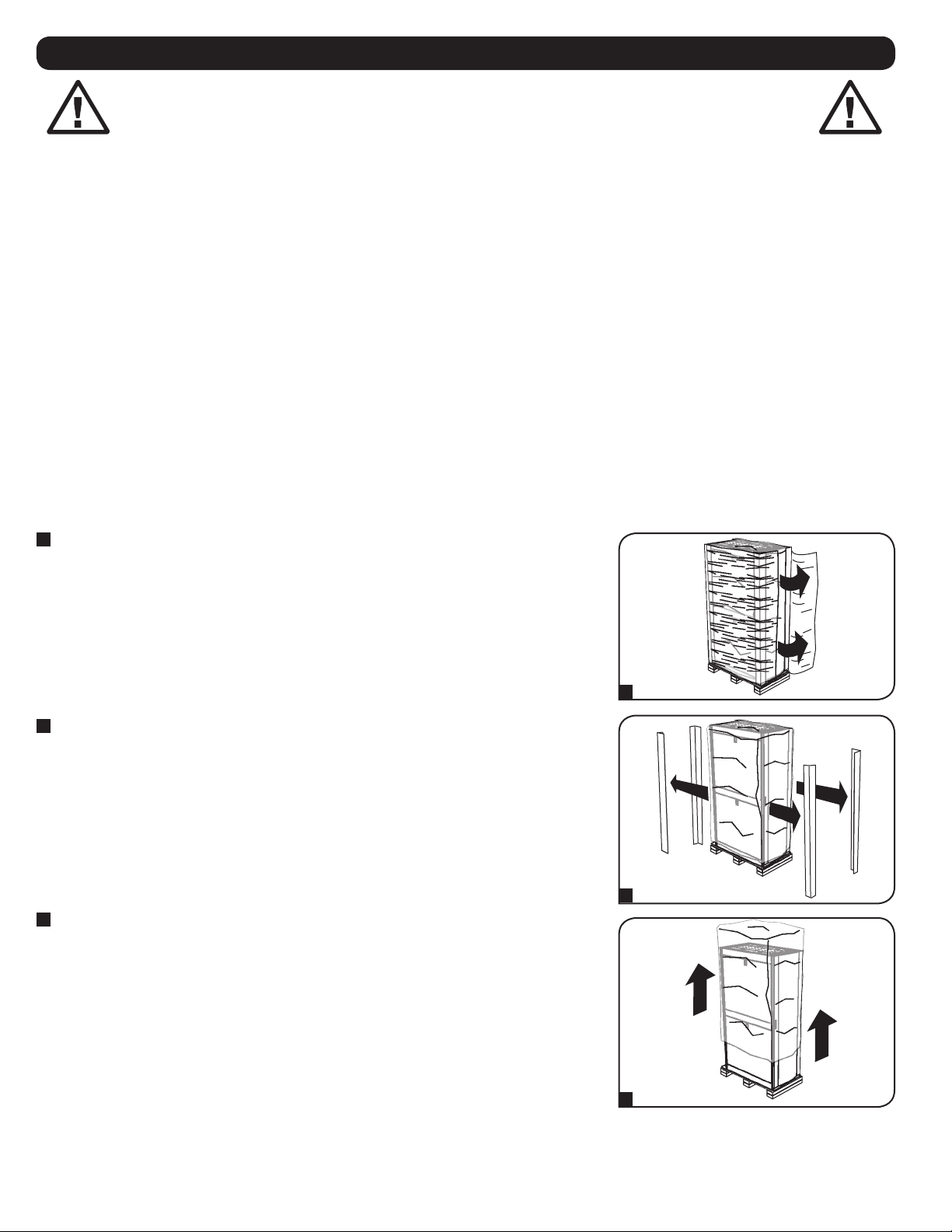
40
Порядок установки шкафа
Внимание! Перед установкой внимательно ознакомьтесь со всеми указаниями и предупреждениями!
ВНИМАНИЕ! Шкаф является крайне тяжеловесным. Не пытайтесь распаковывать, перемещать или устанавливать шкаф в одиночку. До момента надлежащей установки и
уравновешивания шкафа существует опасность его опрокидывания с возможным причинением травм и/или имущественного ущерба. Будьте предельно осторожны при
перемещении шкафа и обязательно следуйте всем указаниям по обращению со шкафом и его установке. Не производите установку оборудования в шкаф до полного
обеспечения его устойчивости.
Подготовка
Шкаф должен быть установлен в конструкционно прочном месте с ровным основанием, способным выдерживать вес самого шкафа, всего оборудования, которое будет установлено внутри него, а
также любых других шкафов и/или оборудования, которые будут установлены вблизи него. Перед распаковкой шкафа следует доставить транспортировочный контейнер как можно ближе к месту
окончательной установки с целью минимизации расстояния, на которое потребуется перемещать модуль после снятия защитной упаковки. Если вы планируете хранение шкафа в течение
длительного периода времени до или после установки, следуйте указаниям, изложенным в разделе Хранение и техническое обслуживание.
Распаковка
ПРИМЕЧАНИЕ. Шкаф следует доставить как можно ближе к предполагаемому месту установки до извлечения из транспортировочного контейнера. Для перемещения
транспортировочного контейнера используйте вилочный погрузчик или вилочную гидравлическую тележку.
Вам потребуются несколько инструментов (в комплект поставки не входят):
• Ключ гаечный рожковый на 13 мм
• Универсальный нож
• Строительный уровень
• Крестообразная отвертка
Кроме того, потребуется следующая оснастка (поставляется в комплекте):
• Винты крепежные с крестообразным шлицем (M6 x 5/8") – 50 шт.
• Гайки закладные (M6) – 50 шт.
• Шайбы чашеобразные нейлоновые – 50 шт.
1
Убедитесь в том, что транспортировочный контейнер находится в устойчивом вертикальном положении, после чего с
помощью универсального ножа разрежьте усадочную пленку, фиксирующую угловые амортизаторы. Во избежание нанесения
царапин на поверхность шкафа или разрезания плотного защитного полиэтиленового мешка под усадочной пленкой
проводите лезвием ножа непосредственно по поверхности угловых амортизаторов. ВНИМАНИЕ! Не наносите царапин на
поверхность шкафа и не разрезайте плотный полиэтиленовый мешок, расположенный под усадочной пленкой.
Не толкайте шкаф и не тяните его на себя в процессе распаковки.
2
Снимите угловые амортизаторы. Сохраните все упаковочные материалы (включая поддон) для последующего использования,
если вы не убеждены в том, что они более не потребуются. Упаковочные материалы подлежат вторичной переработке.
3
Снимите со шкафа плотный полиэтиленовый мешок. Осмотрите шкаф на предмет наличия каких-либо повреждений или
незакрепленных деталей. Убедитесь в наличии всех деталей. В случае отсутствия или повреждения каких-либо деталей
обратитесь за помощью в компанию Tripp Lite. Не пользуйтесь шкафом в случае его повреждения.
1
2
3
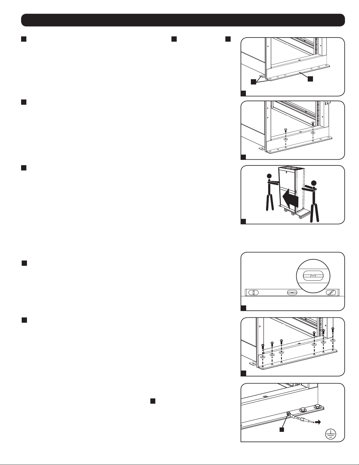
41
Порядок установки шкафа
4
Откройте ключом дверцы шкафа и найдите сейсмостойкие (для 4-й зоны) кронштейны
A
и усиливающие кронштейны
B
, с
помощью которых он прикреплен к транспортировочному поддону. Примечание. Ключи поставляются в дополнительной
коробке, прикрепленной к коробке с боковыми панелями.
5
С помощью рожкового гаечного ключа на 13 мм выверните болты, которыми шкаф прикреплен к транспортировочному
поддону. Соблюдайте предельную осторожность, поскольку после вывертывания болтов возможно непредвиденное
перемещение шкафа. Сохраните усиливающие кронштейны и детали для их крепления с целью последующего использования.
6
По меньшей мере один человек должен находиться перед шкафом и один человек — позади него. Осторожно снимите шкаф
с поддона и расположите его в желаемом месте. ВНИМАНИЕ! Для снятия шкафа с поддона требуется не менее двух
человек. При перемещении шкафа соблюдайте предельную осторожность.
При необходимости шкаф можно приподнять путем ввертывания 4 рым-болтов диаметром M8 (в комплект поставки не входят) в
резьбовые отверстия вблизи верхних углов каркаса шкафа. Для этой цели следует использовать стальные болты с классом
прочности по ISO не ниже 8.8. 4 таких болта способны выдерживать вес шкафа и до 450 кг установленного в нем оборудования.
ВНИМАНИЕ! Подъем шкафа должен осуществляться только опытными специалистами по обслуживанию
оборудования. Следуйте всем применимым к данному случаю указаниям по технике безопасности и нормативным
предписаниям, используя для этого соответствующее оборудование и оснастку.
Размещение
Примечание. Перед началом данной процедуры необходимо обеспечить наличие надлежащих анкерных приспособлений.
1
Для проверки уклона пола в предполагаемом месте установки используйте строительный уровень. Если уклон пола
превышает 1%, выберите для установки другое место.
2
Для крепления шкафа к строительной конструкции с целью обеспечения устойчивости прикрепите основание шкафа и
сейсмостойкие (для 4-й зоны) кронштейны к предварительно закрепленным в полу анкерным приспособлениям с помощью
крепежных изделий диаметром M8 (в комплект поставки не входят). Затяните крепежные изделия с помощью
динамометрического ключа.
Заземление
Все детали шкафа заземляются через его каркас. Соедините каркас шкафа непосредственно с шиной заземления своего объекта
при помощи провода калибром 8 AWG (3,264 мм) и одного из приспособлений
A
, использовавшихся для крепления шкафа к
полу
. Выверните одно из приспособлений для подключения заземляющего провода, а затем снова затяните его для обеспечения
надежного соединения. ВНИМАНИЕ! Каждый шкаф должен подсоединяться к шине заземления по отдельности.
Пользование незаземленным шкафом не допускается.
1
2
4
5
6
ПОЛ
ЗАЗЕМЛЕНИЕ
A
B
A

42
Компоновка шкафа
Установка/снятие передней и задней дверец
ВНИМАНИЕ! Не пытайтесь навешивать и снимать дверцы шкафа в одиночку
Снятие дверцы
1
Отсоедините провод заземления дверцы.
2
Откройте дверцу до того положения, в котором она окажется перпендикулярной (под углом 90 градусов к) передней
плоскости шкафа.
3
Поднимите дверцу и снимите ее с петель шкафа.
Для установки дверцы на место следует повторить шаги 1-3 в обратном порядке.
(Опционально) Если этот шкаф соединен с другим шкафом, поверните дверцу обратно в сторону шкафа при ее снятии с петель.
Перестановка передней дверцы
ВНИМАНИЕ! Не пытайтесь перевешивать переднюю дверцу на другую сторону в одиночку.
1
Выверните винт, соединяющий провод заземления с внутренней поверхностью дверцы.
2
Выверните 2 винта, обеспечивающие крепление дверной ручки к дверце. Снимите дверную ручку.
90°
1
1
2
2
3
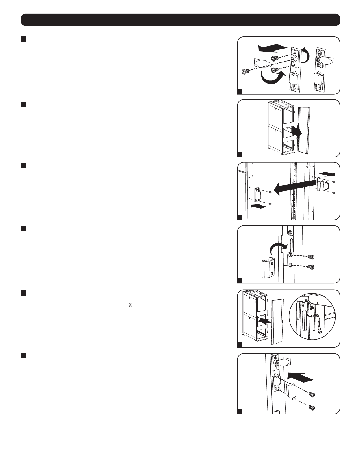
43
Компоновка шкафа
3
Выверните винт и снимите шайбу с тыльной стороны дверной ручки, после чего выньте запорный механизм. Поверните
шайбу запорного механизма на 90 градусов против часовой стрелки и разверните защелку таким образом, чтобы она была
обращена в противоположную сторону, а затем с помощью винта и шайбы прикрепите защелку обратно к тыльной стороне
дверной ручки.
4
Снимите дверцу в порядке, изложенном в предыдущем разделе.
5
Снимите дверные петли со шкафа, разверните их на 180 градусов и закрепите на противоположной стороне шкафа.
Примечание. В точках крепления дверных петель на противоположной стороне находятся пластмассовые заглушки,
вставленные в резьбовые отверстия. Выньте заглушки и вставьте их в отверстия, первоначально использовавшиеся для
крепления дверных петель.
6
Выверните 2 петлевых механизма из петлевых пазов с внутренней стороны дверцы и закрепите каждый из них, используя
для этой цели группу резьбовых отверстий, расположенную непосредственно напротив тех, которые использовались
первоначально.
7
Разверните дверцу на 180 градусов и установите ее обратно на шкаф. Не забудьте подсоединить провод заземления к
внутренней поверхности дверцы в точке крепления, расположенной ближе всех к петле в верхней части дверцы. Эта точка
крепления обозначена символом заземляющего соединения: .
8
Установите на место дверную ручку.
3
6
4
7
5
8

44
Установка/снятие верхней панели
ВНИМАНИЕ! Не пытайтесь использовать верхнюю панель шкафа для размещения тяжелых предметов за исключением случаев, явным образом описанных и одобренных
компанией Tripp Lite. Не пытайтесь устанавливать и снимать верхнюю панель шкафа в одиночку.
Компоновка шкафа
Установка/снятие боковых панелей
Снятие боковой панели
1
Откройте защелку, сдвинув ее по направлению вниз.
2
Наклоните верхнюю часть панели по направлению от шкафа.
Снятие верхней панели
1
Потяните на себя 2 штифта, расположенные в задней части верхней панели. Удерживая штифты, вытолкните верхнюю панель
по направлению вверх.
2
Выньте язычки верхней панели
A
из ее монтажных пазов
B
в каркасе шкафа.
3
Снимите верхнюю панель со шкафа.
Для установки верхней панели на место следует повторить шаги 1-3 в обратном порядке.
2
1
1
2
B
A
3
1
2
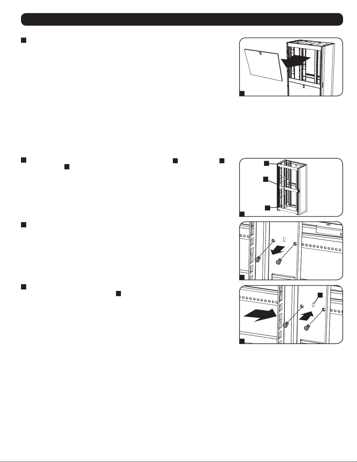
45
Компоновка шкафа
Регулировка монтажных и кабельных направляющих
ВНИМАНИЕ! Не пытайтесь регулировать направляющие в одиночку. Не пытайтесь регулировать направляющие при установленном в шкаф оборудовании. Не пытайтесь
использовать направляющие без установки винтов (по 6 на каждую направляющую).
4 монтажные направляющие устанавливаются на заводе-изготовителе и рассчитаны на размещение оборудования с монтажной глубиной 30" (762 мм). Не регулируйте монтажные направляющие
за исключением тех случаев, когда для устанавливаемого вами оборудования требуется другая монтажная глубина. Передняя и задняя группы направляющих могут регулироваться независимо
друг от друга с шагом 6 мм для получения глубины монтажа от 101,6 до 1066,8 мм.
3
Выньте панель из фиксатора.
Для установки боковой панели на место следует повторить шаги 1-3 в обратном порядке.
1
Каждая направляющая крепится к шкафу при помощи 6 винтов: 1 пары у верхней балки
A
, 1 пары у средней балки
B
и 1
пары у нижней балки
C
.
2
Выверните винты, которыми каждая из задних монтажных направляющих крепится к шкафу. (При необходимости
регулировки передних направляющих вы также можете вывернуть винты, отвечающие за их крепление).
3
Сдвиньте монтажные направляющие на желаемую глубину и снова закрепите их с помощью винтов, вывернутых на Шаге 2.
Точки крепления направляющих имеют обозначение
A
, что поможет вам установить каждую пару направляющих на одной
и той же глубине.
Глубина установки двух направляющих для оптимизации кабельных соединений регулируется
аналогичным образом.
4 5 6 3 4 5 6 7 8 9 0 1 2
3
8
6 7 8 9 0 1 2 3 4
5 6 0 1 2 3
5
3
1
2
3
A
A
B
C

46
Компоновка шкафа
2
Каждый шкаф оснащен 2 скобами для секционирования
A
, соответствующими точкам секционирования
B
на соседнем
шкафу. В точках секционирования уже находятся крепежные болты. Извлеките болт и шайбу из каждой точки
секционирования в соседнем шкафу.
3
Ослабьте все болты, обеспечивающие крепление скоб для секционирования, и поверните каждую из них на 180 градусов в
сторону соседнего шкафа, совместив каждую скобу с соответствующей точкой секционирования на соседнем шкафу.
4
Присоедините каждую скобу к соседнему шкафу с помощью болтов и шайб, извлеченных на шаге 2, но не затягивайте болты
полностью. При необходимости отрегулируйте положение шкафов. После присоединения всех скоб и подтверждения того, что
шкафы не нуждаются в дальнейшей корректировке положения, затяните все болты.
Примечание: при желании перед объединением шкафов можно снять дверцы. Последующая установка дверец на место не
является обязательной. Если вы желаете обеспечить возможность свободного перемещения между шкафами, то перед их
установкой в ряд следует демонтировать внутренние боковые панели.
Совмещение шкафов (установка в ряд)
ВНИМАНИЕ! Объединение шкафов не может служить заменой обеспечению их устойчивости. Каждый шкаф, установленный в ряд с объединенными с ним шкафами, требует
тех же действий по обеспечению устойчивости, что и отдельно стоящий шкаф.
Примечание. Данный метод составления секционного шкафа предназначен специально для объединения шкафов модели SR42UBZ4. Для шкафов других моделей используются иные способы
объединения. См. руководство пользователя шкафа соответствующей модели.
1
Расположите шкафы таким образом, чтобы они могли быть установлены в ряд.
2
3
4
A
B
180°
1

47
Установка оборудования
ВНИМАНИЕ! Не устанавливайте оборудование до обеспечения устойчивости шкафа. Сначала установите оборудование, которое следует разместить в нижней части шкафа.
Устанавливайте оборудование начиная с низа шкафа по направлению вверх — и ни в коем случае не наоборот. При использовании направляющих для установки
оборудования соблюдайте осторожность при их выдвижении. Не выдвигайте более одной группы направляющих одновременно. Старайтесь не выдвигать направляющие для
установки оборудования, расположенные в верхней части шкафа.
Примечание. Квадратные отверстия в середине каждого шкафа пронумерованы и имеют небольшую надсечку для удобства распознавания. В каждом отдельном шкафу имеется место, где
располагается нумерованное отверстие и отверстия, находящиеся непосредственно над и под ним.
Установка/снятие закладных гаек
ВНИМАНИЕ! Отгибы кромок закладных гаек должны зацепляться за боковые, а не верхний и нижний края квадратного отверстия в направляющей. Для обеспечения
правильности установки оборудования следуйте указаниям, изложенным в сопроводительной документации к нему.
Установка закладных гаек
1
Найдите нумерованные квадратные отверстия в монтажных направляющих, которые планируется использовать для
установки оборудования. Вставьте закладные гайки (из комплекта) в квадратные отверстия с целью обеспечения точки
крепления для монтажных винтов (поставляемых в комплекте). Примечание. Для определения необходимого количества
закладных гаек и мест их установки ознакомьтесь с сопроводительной документацией к вашему оборудованию.
2
Проденьте один из отгибов кромки закладной гайки через квадратное отверстие с внутренней стороны монтажной
направляющей. Вдавите ее по направлению к боковому краю квадратного отверстия. Отгибы кромок закладных гаек должны
зацепляться за боковые, а не верхний и нижний края квадратного отверстия.
3
Слегка надавите на закладную гайку по бокам, что позволит другому отгибу кромки пройти через квадратное отверстие. При
правильной установке закладной гайки оба отгиба ее кромок выдаются с обратной стороны квадратного отверстия и видны
на внешней поверхности монтажной направляющей. Повторяйте шаги 1-3 до тех пор, пока не будут установлены все
необходимые закладные гайки.
4
После установки необходимых закладных гаек прикрепите свое оборудование к стоечной направляющей с помощью
монтажных винтов и чашеобразных шайб из комплекта. Поместите чашеобразные шайбы между винтами и монтажными
кронштейнами для крепления оборудования. Примечание. В комплект поставки вашего оборудования могут также входить
монтажные приспособления. Перед установкой своего оборудования ознакомьтесь с указаниями по монтажу, поставляемыми
в комплекте с ним.
Для извлечения закладных гаек повторите шаги 1-3 в обратном порядке.
Примечание. При желании установку и извлечение закладных гаек можно производить с помощью специального инструмента (в
комплект поставки не входит).
24
25
23
24
25
23
2
4
24
2
1 шкаф
20
19
22
21
20
19
21
20
19
21
20
19
21
1
2
3
4

48
1111 W. 35th Street, Chicago, IL 60609 USA • www.tripplite.com/support
Технические характеристики
Максимально допустимая
нагрузка
Габаритные размеры Транспортные габариты
Модель Стационарная Роликовая Высота Ширина Глубина Масса Высота Ширина Глубина Масса
SR42UBZ4 1361 кг 1021 кг 1994 мм 600 мм 1093 мм 161 кг 2159 мм 661 мм 1143 мм 179 кг
Хранение и техническое обслуживание
Хранение
Корпус должен храниться в помещении с контролируемым микроклиматом вдали от источников влаги, экстремальных температур, воспламеняющихся жидкостей и газов, электропроводных
загрязнителей, пыли и прямого солнечного света. По возможности храните шкаф в его заводской транспортной упаковке.
Техническое обслуживание
На приобретенное вами изделие марки Tripp Lite распространяется действие гарантии, условия которой изложены в настоящем руководстве. Кроме того, компания Tripp Lite предлагает ряд
Программ расширенной гарантии и обслуживания на объекте. Более подробная информация о техническом обслуживании изложена на странице www.tripplite.com/support. Перед возвратом своего
изделия в целях технического обслуживания просьба выполнить следующие действия:
1. Внимательно изучите порядок монтажа и эксплуатации устройства, приведенный в настоящем руководстве, во избежание проблем, которые могут возникнуть в ходе работы из-за
неправильного понимания приведенных в руководстве указаний.
2. Если проблему решить не удалось, не обращайтесь к продавцу и не возвращайте изделие ему. В этом случае посетите интернет-страницу по адресу: www.tripplite.com/support.
3. Если возникшая проблема требует проведения ремонта или технического обслуживания, зайдите на страницу www.tripplite.com/support и нажмите на ссылку Product Returns (Возврат изделий).
Здесь вы можете запросить номер Returned Material Authorization (RMA) (разрешение на возврат материалов), который необходим для проведения технического обслуживания. Для заполнения
этой простой онлайн-формы потребуется указать номер модели и серийный номер изделия, а также общие сведения о покупателе. Номер RMA вместе с указаниями по транспортировке будет
направлен вам по электронной почте. Действие гарантии не распространяется на какие бы то ни было убытки (прямые, косвенные, последующие или вызванные особыми обстоятельствами),
связанные с транспортировкой изделия в адрес компании Tripp Lite или ее уполномоченного сервисного центра. Стоимость транспортировки изделий в адрес компании Tripp Lite или ее
уполномоченного сервисного центра должна быть оплачена авансом. Номер RMA должен быть указан на внешней стороне упаковки. Если возврат изделия производится в период действия
гарантии, то необходимо приложить копию товарного чека продавца. Возврат изделия для проведения ремонта или технического обслуживания должен производиться застрахованным
перевозчиком по адресу, указанному в ответе на ваш запрос номера RMA.
Гарантийные обязательства
Условия 5-летней ограниченной гарантии
Продавец гарантирует отсутствие изначальных дефектов материала или изготовления в течение 5 лет с момента первоначальной покупки данного изделия при условии его использования в соответствии со всеми применимыми к нему
указаниями. В случае проявления каких-либо дефектов материала или изготовления в течение указанного периода Продавец осуществляет ремонт или замену данного изделия исключительно по своему усмотрению.
ДЕЙСТВИЕ НАСТОЯЩЕЙ ГАРАНТИИ НЕ РАСПРОСТРАНЯЕТСЯ НА СЛУЧАИ ЕСТЕСТВЕННОГО ИЗНОСА ИЛИ ПОВРЕЖДЕНИЯ В РЕЗУЛЬТАТЕ АВАРИИ, НЕНАДЛЕЖАЩЕГО ИСПОЛЬЗОВАНИЯ, НАРУШЕНИЯ ПРАВИЛ ЭКСПЛУАТАЦИИ ИЛИ ХАЛАТНОСТИ. ПРОДАВЕЦ НЕ
ПРЕДОСТАВЛЯЕТ НИКАКИХ ЯВНО ВЫРАЖЕННЫХ ГАРАНТИЙ ЗА ИСКЛЮЧЕНИЕМ ПРЯМО ИЗЛОЖЕННОЙ В НАСТОЯЩЕМ ДОКУМЕНТЕ. ЗА ИСКЛЮЧЕНИЕМ СЛУЧАЕВ, ЗАПРЕЩЕННЫХ ДЕЙСТВУЮЩИМ ЗАКОНОДАТЕЛЬСТВОМ, ВСЕ ПОДРАЗУМЕВАЕМЫЕ
ГАРАНТИИ, ВКЛЮЧАЯ ВСЕ ГАРАНТИИ ПРИГОДНОСТИ ДЛЯ ПРОДАЖИ ИЛИ ИСПОЛЬЗОВАНИЯ ПО НАЗНАЧЕНИЮ, ОГРАНИЧЕНЫ ПО ПРОДОЛЖИТЕЛЬНОСТИ ДЕЙСТВИЯ ВЫШЕУКАЗАННЫМ ГАРАНТИЙНЫМ СРОКОМ; КРОМЕ ТОГО, ИЗ НАСТОЯЩЕЙ ГАРАНТИИ
ЯВНЫМ ОБРАЗОМ ИСКЛЮЧАЮТСЯ ВСЕ ПОБОЧНЫЕ, СЛУЧАЙНЫЕ И КОСВЕННЫЕ УБЫТКИ. (В некоторых штатах не допускается введение ограничений на продолжительность действия тех или иных подразумеваемых гарантий, а в некоторых -
исключение или ограничение размера побочных или косвенных убытков. В этих случаях вышеизложенные ограничения или исключения могут на вас не распространяться. Настоящая гарантия предоставляет вам конкретные юридические
права, а набор других ваших прав может быть различным в зависимости от юрисдикции).
ВНИМАНИЕ! До начала использования данного устройства пользователь должен убедиться в том, что оно является пригодным, соответствующим или безопасным для предполагаемого применения. В связи с большим разнообразием
конкретных применений производитель не дает каких-либо заверений или гарантий относительно пригодности данных изделий для какого-либо конкретного применения или их соответствия каким-либо конкретным требованиям.
Примечание относительно маркировки
На данное изделие нанесен следующий символ: Заземление
19-02-238 93-3065_revC