User Manual
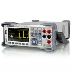
SDM3055 Digital Multimeter
UM06035-E02A
2014 SIGLENT TECHNOLOGIES CO., LTD

SIGLENT
Copyright and Statement
Copyright
SIGLENT TECHNOLOGIES CO., LTD. All rights reserved.
Trademark Information
SIGLENT is registered trademark of SIGLENT TECHNOLOGIES CO., LTD.
Statement
● SIGLENT products are protected by patent laws in and outside of the P.R.
China.
● SIGLENT reserves the rights to change the specification and price.
● Information in this publication replaces all previous corresponding
published material.
● Contents in this manual are not allowed to be copied, extracted or
translated in any form or by any means without SIGLENT’s permission.

SIGLENT
II SDM3055 Digital Multimeter
General Safety Summary
Read the following safety precautions carefully to avoid any personal injuries
or damages to the instrument and any products connected to it. To avoid
potential hazards, please use the instrument as specified.
Use proper power line.
It’s only allowed to use the special power line which is approved by local
state.
Ground the instrument.
The instrument is grounded through the protective terra conductor of the
power line. The ground conductor must be connected to the earth to avoid
electric shock. Make sure the instrument is grounded correctly before
connecting its input or output terminals.
Connect the signal wire correctly
The potential of the signal wire is equal to the earth, so do not connect the
signal wire to a high voltage.
Observe all terminal ratings
Please observe all ratings and sign instructions on the instrument to avoid fire
or electric shock. Before connecting the instrument, please read the manual
carefully to gain more information about the ratings.
Do not operate with suspected failures
If you suspect that the product is damaged, please contact SIGLENT’s
qualified service personnel to inspect it. Any repair and adjustment to the
product or replacing a component should be done by qualified personnel
only.
Avoid circuit or wire exposure
Don’t touch exposed contacts or components when the power is on.
Don’t operate without covers.
Don’t operate the instrument with covers or panels removed.
Use proper fuse.
It’s only allowed to use the specified fuse for the instrument.
Use proper over-voltage protection.
Make sure there is no over-voltage (like voltage caused by thunder and
lightning) reaching to the instrument, otherwise the operator may suffer an
electric shock.

SIGLENT
SDM3055 Digital Multimeter III
Antistatic protection.
Static electricity will cause damages to the instrument, so test in antistatic
areas as far as possible. Ground its inner and outer conductors to release the
static electricity temporarily before connecting the cable to the instrument.
Keep good ventilation.
Improper ventilation will cause the rise of the instrument’s temperature. Keep
good ventilation and check the vent and fan regularly when using it.
Keep the surface of the instrument clean and dry.
Do not operate in wet or damp conditions.
Do not operate in flammable or explosive environment.
The disturbance test of all the models meets the limit values of A in the
standard of EN 61326-1:2013.
Input terminal protection limitation
Protection limitation is defined for the input terminal:
1. Main input
(HI and LO)terminal
HI and LO terminals are used for Voltage, Resistance, Capacitance,
Continuity, Frequency and Diode measurement. Two protection limitations
are defined:
HI-LO protection limitation: 1000VDC or 750AVC. It’s the maximum
measurable voltage. The limitation can be expressed as 1000Vpk.
LO-ground protection limitation : LO terminal can “float” 500Vpk
relative to the ground safely. The maximum protection limitation of HI terminal
relative to the ground is 1000Vpk. Therefore, the sum of the “float” voltage
and the measured voltage can’t exceed 1000Vpk.
2. Sampling (HI Sense and LO Sense) terminal
HI Sense and LO Sense are used for 4-wire Resistance measurement. Two
protection limitations are defined:
HI Sense-LO Sense protection limitation: 2000Vpk.
LO Sense-LO Sense protection limitation: 2Vpk.

SIGLENT
IV SDM3055 Digital Multimeter
3. Current input (I) terminal
I and LO terminals are used for current measurement. The maximum
current which go through the I terminal is limited to 10A by the fuse on the
back panel.
NOTE:
Voltage on the current input terminal corresponds to voltage on LO terminal.
To keep good protection, only use the fuse of specified type and level to
replace this fuse.
IEC Measurement Category II Over-voltage Protection
SDM3055 Digital Multimeter provides over-voltage protection for line-voltage
mains connections meeting both of the following conditions to avoid the
danger of electric shock:
The HI and LO input terminals are connected to the mains under
Measurement Category II conditions as following.
The maximum line voltage of the mains is 600VAC.
WARNING:
IEC Measurement Category II includes electrical devices connected to mains
at an outlet on a branch circuit, such as most small appliances, test
equipments, and other devices that plug into a branch outlet or socket.
SDM3055 is capable of making measurements with the HI and LO inputs
connected to mains in such devices (up to 600VAC) or the branch outlet itself.
However, the HI and LO terminals of SDM3055 can’t be connected to mains
in permanently installed electrical devices such as the main circuit-breaker
panels, sub-panel disconnected boxes and permanently wired motors. Such
devices and circuits are prone to exceed the protection limits of SDM3055.
NOTE:
Voltages above 600VAC only can be measured in circuits that are isolated
from mains. However, there may be transient over-voltage in circuits that are
isolated from mains. SDM3055 is able to withstand occasional transient
over-voltage up to 4000Vpk. Please don’t use this instrument to measure
circuits that transient over-voltage may exceed this level.
SIGLENT
SDM3055 Digital Multimeter V
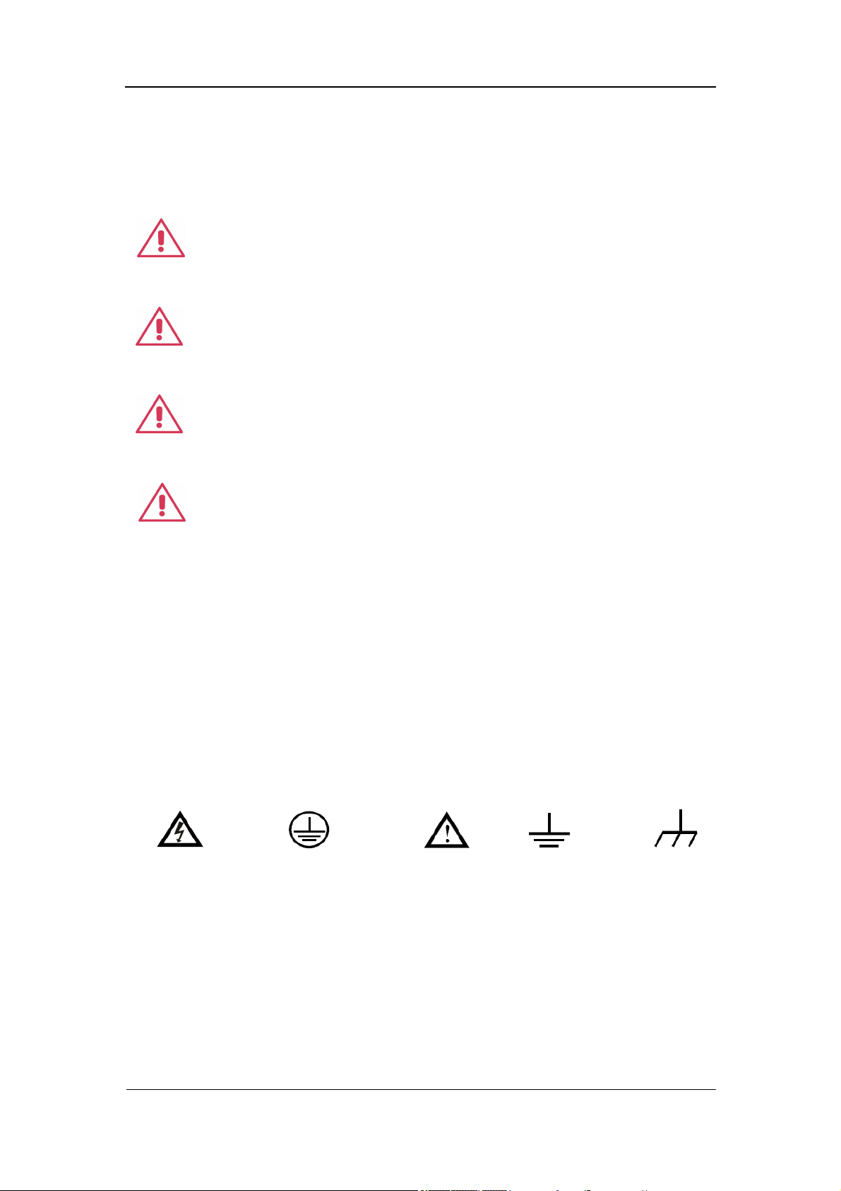
Safety Terms and Symbols
Terms in this manual. Terms may appear in this manual.
Terms used on the instrument. Terms may appear on the instrument:
DANGER indicates an injury or hazard that may immediately happen.
WARNING indicates an injury or hazard that may not immediately happen.
CAUTION indicates that a potential damage to the instrument or other
property might occur.
Symbols used on the instrument. Symbols may appear on the instrument.
WARNING: Warning statements indicate the conditions and
behaviors that could result in injury or loss of life.
CAUTION: Caution statements indicate the conditions and
behaviors that could result in damage to this product or other
properties.
CAT I (1000V): IEC Measurement Category I. The highest
measurable voltage is 1000Vpk in the HI-LO terminal.
properties.
CAT II (600V): IEC Measurement Category II. Inputs may be
connected to mains (up to 600VAC) under Category II overvoltage
conditions.
Hazardous
Voltage
Protective Earth
Ground
Warning Test
Ground
Chassis
Ground

SIGLENT
VI SDM3055 Digital Multimeter
Introduction of SDM3055
SDM3055 is a 5½ dual-display instrument designed with 5½ digits readings
resolution and dual-display, especially fitting to the needs of high-precision,
multifunction, and automation measurements. It realized a combination of
basic measurement functions, multiple math functions, and display functions,
etc.
SDM3055 holds a 4.3 inch color TFT-LCD display screen. Its clear keyboard
layout and operation hints make it easier and agility to use. Besides, it
supports multi-interface such as USB Device & Host, LAN and GPIB (only for
SDM3055A), which can meet users’ demand furthest.
Main Features:
4.3 inch color TFT-LCD display screen with 480*272 high resolutions
Real 5½ digits readings resolution
Up to 150rdgs/S measurement speed
True-RMS AC Voltage and AC Current measurements
1 Gb Nand Flash size, mass storage configuration files and data files
Built-in cold terminal compensation for thermocouple
Support standard SCPI and control software on PC, compatible with
commands of main stream multimeters
Supports dual-display function, Chinese and English menu
Built-in help system, convenient to acquire information
Support USB Device, USB Host, LAN, and GPIB (only for SDM3055A)
interfaces
Configuration and measured data can be imported or exported via VXI 11,
USBTMC and USB flash drive, which is convenient for users to modify,
view and backup

SIGLENT
SDM3055 Digital Multimeter VII
Abstract
The manual mainly introduces corresponding information of operating the
SDM3055 Digital Multimeter. It contains these chapters:
Chapter 1 Quick Start
Guide you to prepare the SDM3055 Digital Multimeter and know about the
Front/Back panel and user interface.
Chapter 2 Function and Operation
Introduce the functions and operations of SDM3055 in details.
Chapter 3 Application Examples
Introduce you how to use strong measurement functions of this instrument
easily through some examples.
Chapter 4 Measurement Tutorial
Guide you to eliminate the errors that may appear during your measurement
and obtain accurate result.
Chapter 5 General Troubleshooting
Provide you some general troubleshooting.
Chapter 6 Appendix
Provide you information about accessories, warranties, troubleshooting,
services and supports.

SIGLENT
VIII SDM3055 Digital Multimeter
Content
Copyright and Statement .............................................................................. II
General Safety Summary............................................................................... II
Safety Terms and Symbols .......................................................................... V
Introduction of SDM3055 ............................................................................. VI
Abstract ....................................................................................................... VII
Content ....................................................................................................... VIII
Chapter 1 Quick Start ................................................................................ 1
General Inspection .................................................................................... 2
To adjust the Handle ................................................................................. 3
Front Panel ............................................................................................... 4
Back Panel ................................................................................................ 5
Power On .................................................................................................. 6
User Interface ........................................................................................... 7
Chapter 2 Function and Operation ........................................................... 8
To Select Measurement Range ................................................................ 9
To Select Measurement Speed .............................................................. 11
Basic Measurement Functions ................................................................ 12
To Measure DC Voltage .................................................................. 13
To Measure DC Current .................................................................. 15
To Measure AC Voltage .................................................................. 17
To Measure AC Current ................................................................... 19
To Measure 2-Wire/4-Wire Resistance ............................................ 21
To Measure Capacitance ................................................................. 25
To Measure Frequency or Period .................................................... 27
To Test Continuity............................................................................ 31
To Test Diode .................................................................................. 33
To Measure Temperature ................................................................ 35
Measurement Parameters ...................................................................... 38
AC Filter ........................................................................................... 38
DC Input Impedance ........................................................................ 39
Short-circuit Resistance ................................................................... 40
Dual-display Function ............................................................................. 41
Utility Function ........................................................................................ 43
Store and Recall .............................................................................. 44
Manage File ..................................................................................... 46
I/O Configuration.............................................................................. 48
Board Test ....................................................................................... 50
Firmware Update ............................................................................. 53
System Setup .................................................................................. 54
Acquire.................................................................................................... 56

SIGLENT
SDM3055 Digital Multimeter IX
Auto Trigger ..................................................................................... 57
Single Trigger .................................................................................. 58
External Trigger ............................................................................... 59
Help System ........................................................................................... 60
Math Function ......................................................................................... 62
Statistics .......................................................................................... 64
Limits ............................................................................................... 66
dBm ................................................................................................. 68
dB .................................................................................................... 69
Relative Value.................................................................................. 70
Display Mode .......................................................................................... 71
Trigger .................................................................................................... 77
Hold Measurement Function ................................................................... 78
Chapter 3 Application Examples ............................................................ 79
Example 1: Reading Statistic Functions.................................................. 80
Example 2: To Eliminate Leads Impedance ............................................ 81
Example 3: dBm Measurement ............................................................... 83
Example 4: dB Measurement .................................................................. 84
Example 5: Limits Test............................................................................ 86
Example 6: Thermocouple setting and measurement ............................. 88
Example 7: To Use Hold Measurement Function ................................... 90
Example 8: To Use Application Software EasySDM ............................... 92
Chapter 4 Measurement Tutorial ............................................................ 93
True RMS AC Measurement ................................................................... 93
Crest Factor Errors (non-sinusoidal inputs) ............................................ 94
Loading Errors (AC Voltage) ................................................................... 95
Application of the Analog Filter ............................................................... 96
Chapter 5 General Troubleshooting....................................................... 97
Chapter 6 Appendix ................................................................................. 98
Appendix A: Accessories ........................................................................ 98
Appendix B: Warranty summary ............................................................. 99
Appendix C: Daily Maintenance and Cleaning ...................................... 100
Appendix D: Contact SIGLENT ............................................................. 101

SIGLENT
SDM3055 Digital Multimeter 1
Chapter 1 Quick Start
General Inspection
Handle Adjustment
The Front Panel
The Back Panel
To Connect Power Line
User Interface
To Use Safety Lock

SIGLENT
2 SDM3055 Digital Multimeter
General Inspection
1. Inspect the shipping container.
Please keep the damaged container or cushioning material until the contents
of the shipment have been checked completely and the instrument has passed
the electrical and mechanical test.
Damages of the instrument caused by the shipment will be compensated by
the shipper or carrier. SIGLENT will not be responsible for the free repair or
replacement.
2. Inspect the instrument.
If there exit any mechanical damages or lacking of components, or the
instrument fails the electrical and mechanical test, please contact your
SIGLENT sales.
3. Check the accessories.
Check the accessories according to the packing list carefully. If there exit any
accessories damaged or missing, please contact your SIGLENT sales.
SIGLENT
SDM3055 Digital Multimeter 3
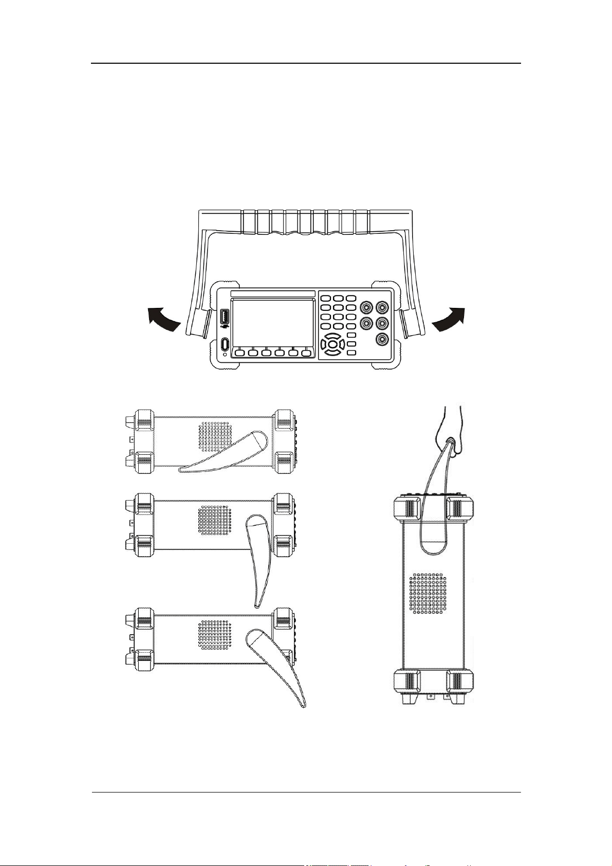
To adjust the Handle
Adjust the handle position of SDM3055 properly to place the instrument stably
so that users can manipulate and observe the display better. Please grip the
handle by the two sides and pull it outward. Then rotate the handle to the
appropriate position. Please operate as the following diagram.
Diagram 1- 1 Handle adjustment
Diagram 1- 2 Horizontal Position Diagram 1- 3 Carrying Position
SIGLENT
4 SDM3055 Digital Multimeter
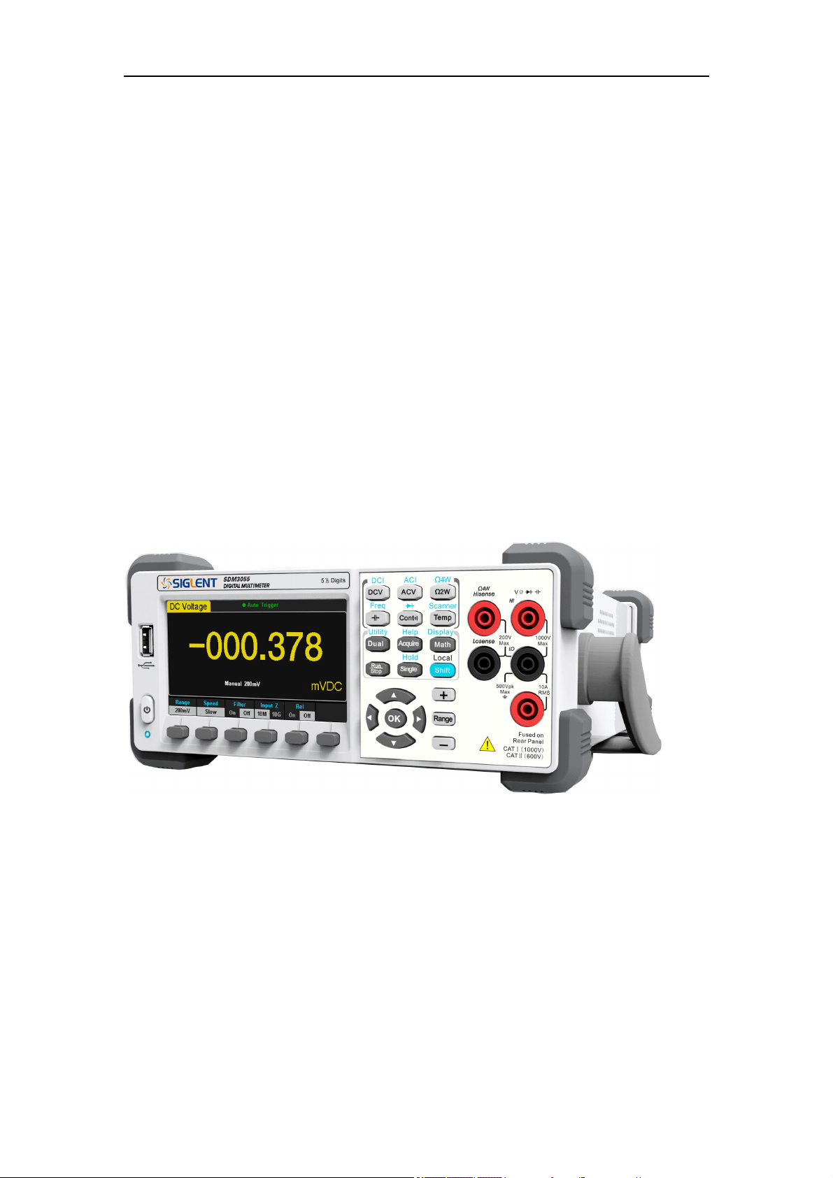
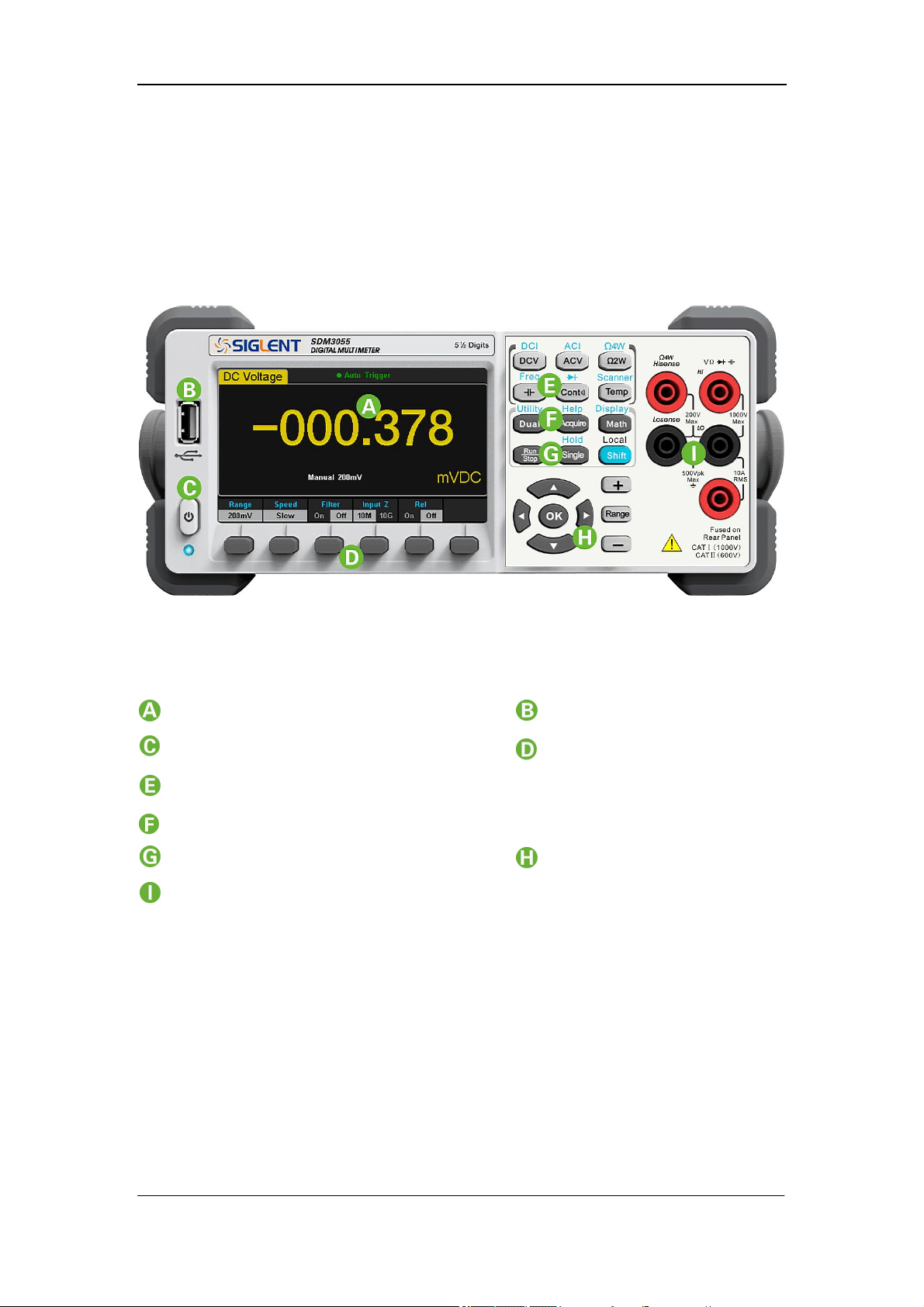
Front Panel
SDM3055 Digital Multimeter provides users with brief and clear front panel.
These control buttons are group by logic and users only need choose
corresponding buttons to carry out basic operations, as shown in Diagram
1-4.
Diagram 1- 4 Front Panel Overview
LCD Display USB Host
Power Key Menu Keys
Basic Measurement Function Keys
Auxiliary Measurement Function Keys
Enable Trig Keys Direction Keys
Signal Input Port
SIGLENT
SDM3055 Digital Multimeter 5
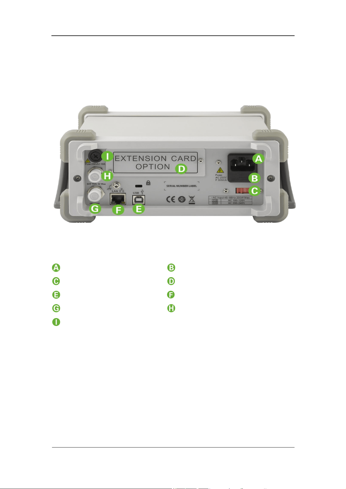
Back Panel
SDM3055 Digital Multimeter’s Back Panel provides users with abundant
interfaces, including USB Device、USB Host、LAN and GPIB(Only for
SDM3055A), as shown in the following diagram.
Diagram 1- 5 Back Panel Overview
Power Socket Power Fuse
AC Voltage Selector Inspection card interface
USB Device(USBTMC) 10/100 Ethernet
VMC Output Ext Trig
Current Input Fuse
NOTE:
SDM3055 doesn’t support GPIB and Inspection Card;
SDM3055A doesn’t support Inspection Card;
SDM3055S doesn’t support GPIB.

SIGLENT
6 SDM3055 Digital Multimeter
Power On
Please power on the instrument as the following steps:
1. Adjust AC Voltage Selector to 110 (100~120V, 45~440Hz, AC) or 220
(200~240V, 50/60Hz, AC) in accordance with power standards in your
country;
2. Connect the instrument to AC supply via power cord supplied by
SIGLENT;
3. The power indicator light on the front panel will glitter slowly;
4. Press the power key on the front panel, the instrument will be started a few
seconds later.
SIGLENT
SDM3055 Digital Multimeter 7
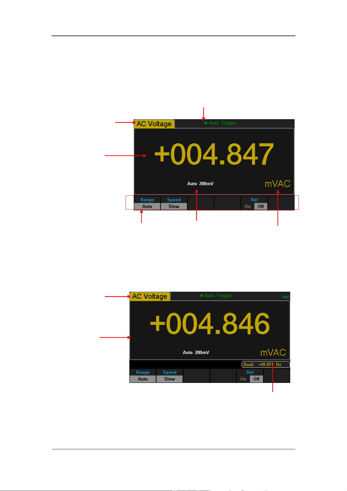
User Interface
Single Display:
Diagram 1- 6 Single Display Interface
Dual-Display:
Diagram 1-7 User Interface
Main Display
Function
Reading
Display
Measurement Range
Trigger Mode
Unit Softkey Menu
Vice-display
Main
Display
Function
Main
Display
SIGLENT
8 SDM3055 Digital Multimeter
Chapter 2 Function and Operation
To Measure DC Voltage / Current
To Measure AC Voltage / Current
To Measure 2-Wire / 4-Wire Resistance
To Measure Frequency / Capacitance
To Test Continuity / Diode
To Measure Temperature / Optional Multiple Scan Card
To use Dual-display Function or Set Up the Utility
Acquire Function or Help System
Math Function or Display Function
Run / Stop
Single Trigger / Hold Measurement Function
To Switch Functions or Return to Local Menu
To Select Measurement Range
SIGLENT
SDM3055 Digital Multimeter 9
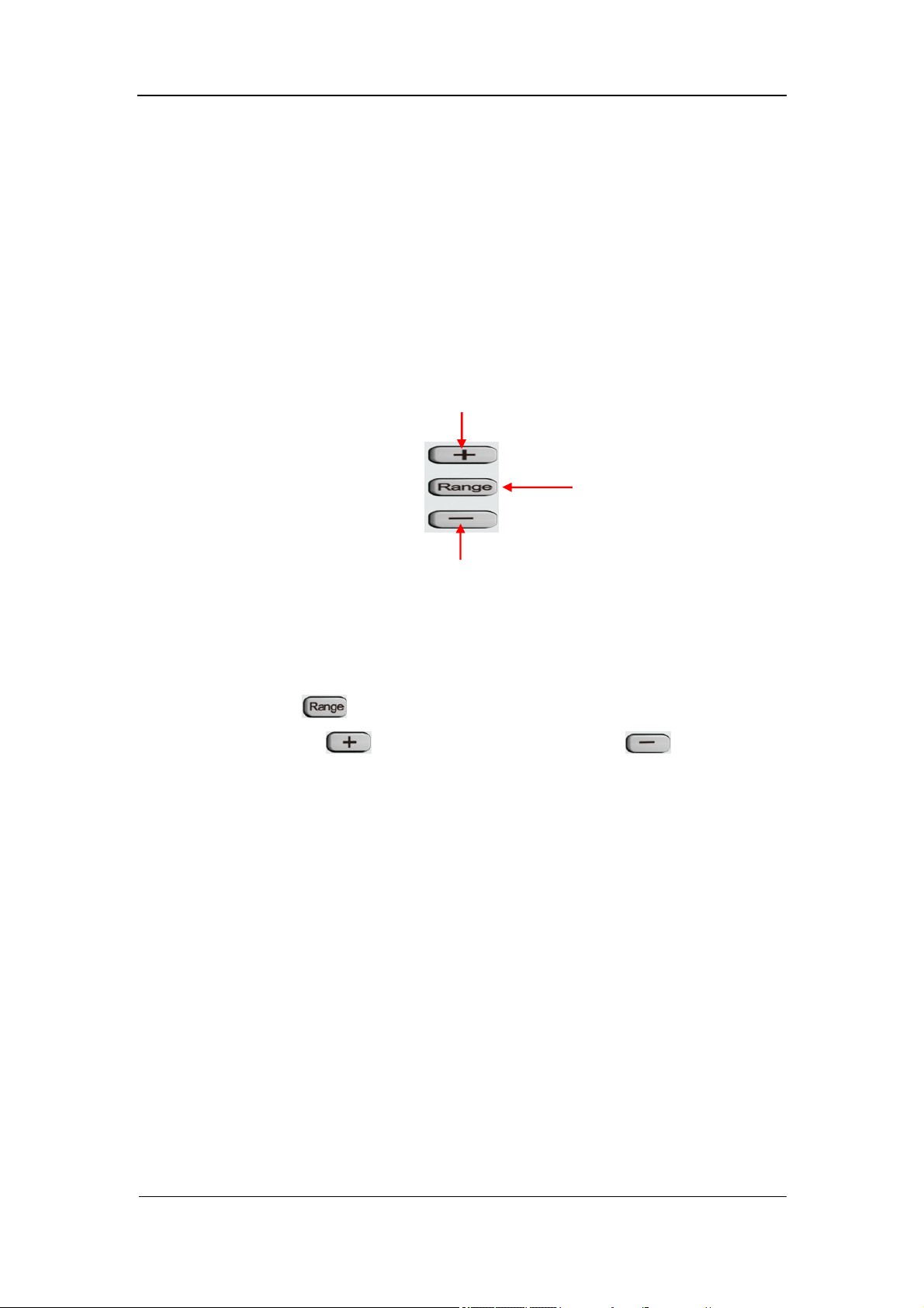
To Select Measurement Range
The Multimeter has two kinds of modes of selecting measurement range:
“Auto” and “Manual”. It can select appropriate range according to the signals
input in Auto mode, which is very convenient for users. While in Manual mode,
you can obtain higher reading precision. Range selection keys are on the right
side of the front panel as the following diagram.
To increase range
To decrease range
Diagram 2- 1 Range Selection Keys
Method 1: By Function keys on the Front Panel
Auto Range: Press to switch between Auto Range and Manual Range.
Manual Range: Press to increase range and press to decrease
range.
Method 2: By softkeys on the measurement main interface as Diagram 2-2.
Auto Range: Press【Auto】to choose Auto Range, meanwhile Manual Range is
forbidden.
Manual Range: Press【200mV】、【2V】、【20V】、【200V】or【1000V】
to choose required range manually. Auto Range is forbidden at this moment.
To switch modes

SIGLENT
10 SDM3055 Digital Multimeter
Diagram 2- 2 Range selection menus
Explanations:
1. When the input signal is beyond the current scope of the measurement
range, the Multimeter will show “overload”.
2. Range option will turn back to default setting “Auto” after restarting and
remote reset.
3. Users are suggested to select “Auto” range so as to protect the instrument
against damage and get exact data as much as possible when it’s hard to
predict the range of measurement.
4. For Dual-display Function, the measurement ranges of Main display and
vice display are similar and can’t be changed independently
5. The range is fixed during testing the Continuity and Diode. The range of
continuity is selected as 2kΩ, while the Diode is 2V.
6. Auto Range is not suitable for measuring current up to 10A. If the signal is
used to I Terminal, users need to choose range manually.
SIGLENT
SDM3055 Digital Multimeter 11
To Select Measurement Speed
The instrument provides three types of measurement rate: 5 reading/s, 50
reading/s and 150 reading/s. 5 reading/s belongs to “Slow” rate; 50 reading/s
belongs to “Middle” rate; 150 reading/s belongs to “Fast” rate.
Measurement speed can be controlled by softkey menu. Press 【Speed】 and
then press 【Slow】,【Middle】or【Fast】to choose measurement speed.
Diagram 2- 3 Range selection menu
Explanations:
1. Three reading rates are available for DCV, ACV, DCI, ACI and 2-Wire/
4-Wire Resistance: “Slow”, “Middle” and “Fast”.
2. There is a linkage for both reading resolution and reading (measurement)
rate.
3. 5 reading/s belongs to 5.5 digit resolution.
4. Both 20 reading/s and 123 reading/s belong to 4.5 digit resolution.
5. The reading resolution of Temperature is fixed at 5.5 digit and “Slow”
respectively.
6. The reading resolutions and measurement rates of both Diode and
Continuity are fixed at 4.5 digit and “Fast” respectively.
7. The reading resolution and measurement rate of the Frequency function
are fixed 5.5 digit and “Slow” respectively.
8. The reading resolution and measurement rate of the Capacitance function
are fixed at 5.5 digit and “Slow” respectively.

SIGLENT
12 SDM3055 Digital Multimeter
Basic Measurement Functions
SDM3055 Digital Multimeters have following basic functions:
To Measure DC Voltage
To Measure AC Voltage
To Measure DC Current
To Measure AC Current
To Measure 2/4-Wire Resistance
To Measure Capacitance
To Test Continuity
To Test Diode
To Measure Frequency or Period
To Measure Temperature
SIGLENT
SDM3055 Digital Multimeter 13
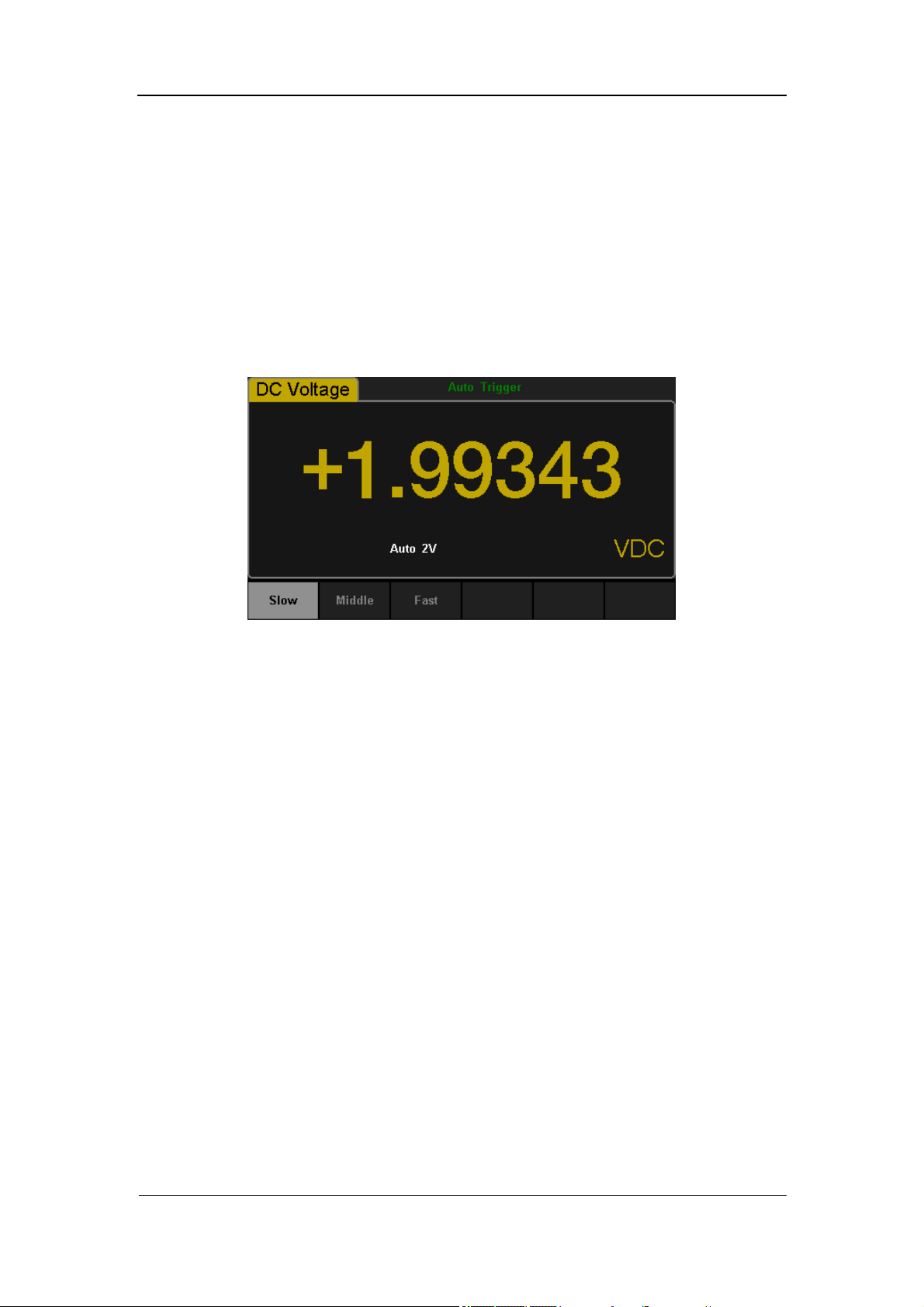
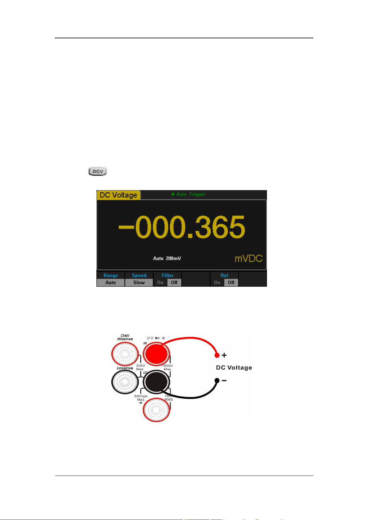
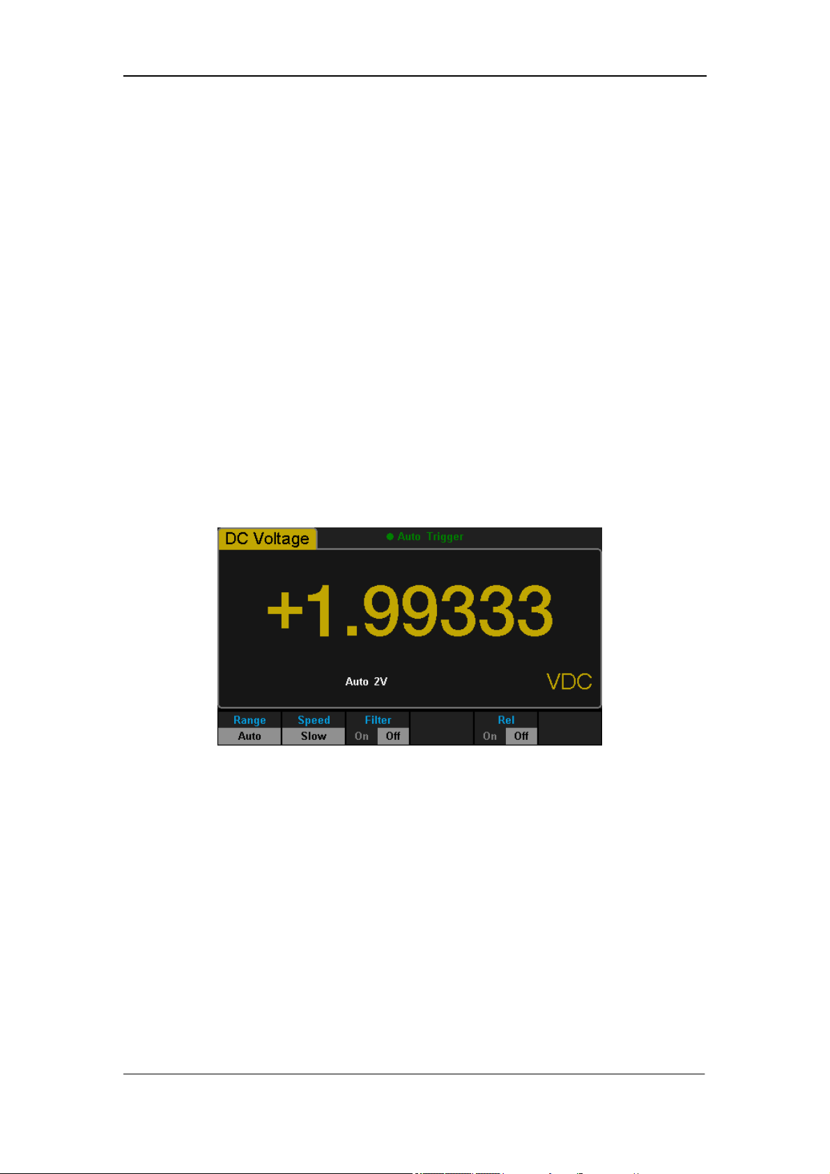
To Measure DC Voltage
The Multimeter enables to measure DC Voltage up to 1000V. The method to
connect and measure DC Voltage will be introduced in details as the following
steps. (NOTE: DC Voltage is always the selected function when the
Multimeter is turned on)
Operating Steps:
1. Press on the front panel to enter the DC Voltage measurement
interface, as shown in Diagram 2- 4.
Diagram 2- 4 DC Voltage Measurement Interface
2. Connect the red lead to terminal Input-HI and black lead to terminal
Input-LO as the following diagram.
Diagram 2- 5 Sketch Map for Measuring DC Voltage

SIGLENT
14 SDM3055 Digital Multimeter
3. Choose a proper voltage range according to the measured circuit.
Table 2- 1 Measurement Characteristics of DC Voltage
Ranges*
200mV、2V、20V、200V、1000V
Input Protection
1000V on all ranges(HI terminal)
Configurable
Range, DC input impedance, Rel
NOTE*:
All the ranges enable to obtain 20% value higher than original except
1000V. Besides, both Manual and Auto are available for setting every
range.
When inputting range is higher than 1000V at 1000V Level, “overload” will
be shown on the screen.
1000V input protection exists in every range.
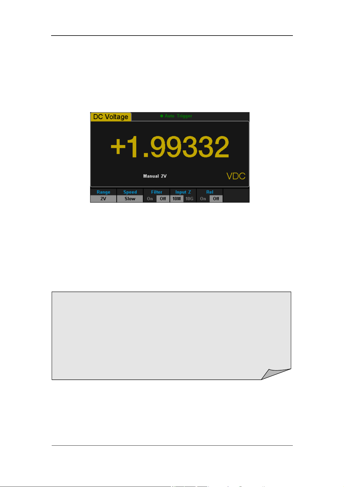
4. Set the DC input impedance (Only for Manual 200mV and 2V ranges).
Press 【Input Z】to set the DC resistance as “10M” (default value) or
“>10G”. Users can execute DC voltage measurement directly without
modifying this parameter which has been setup before leaving factory.
5. Set AC Filter function.
Press 【Filter】to open or close the AC Filter. (NOTE: Only DC Voltage and
DC Current have this function.)
6. Set relative value (Optional operation).
Press 【Rel】to open or close Relative math function. When it is opened, the
reading displayed is a relative value which comes from the result of actual
measurement value subtracts the value that has been set. (Please refer to
“ Math Functions” in Chapter 2 to know about the details.)
7. Read measurement result.
Select required measurement rate (reading rate) by pressing 【Speed】
and read the measurement result.
8. View history data.
There are four types of way to view historical data: “Number”, “Bar
Meter” ”Trend Chart” and “Histogram”.

SIGLENT
SDM3055 Digital Multimeter 15
To Measure DC Current
The Multimeter enables to measure DC Current up to 10A. The method to
connect and measure DC Current will be introduced in details as the following
steps.
Operating Steps:
1. Press and on the front panel to enter the DC Current
measurement interface, as shown in Diagram 2- 6.
Diagram 2- 6 DC Voltage Measurement Interface
2. Connect the red lead to terminal Input-I and black lead to terminal
Input-LO as the following diagram.
Diagram 2- 7 Sketch Map for Measuring DC Current

SIGLENT
16 SDM3055 Digital Multimeter
3. Choose a proper current range according to the measured circuit.
Table 2- 2 Measurement Characteristics of DC Current
Ranges*
200μA、2mA、20mA、200mA、2A、10A
Input Protection 10A(back panel), 12A(inside the instrument)
Configurable
Range, Rel
NOTE*:
All the ranges enable to obtain 20% value higher than original except 10A.
Besides, both Manual and Auto are available for setting every range.
4. Set AC Filter function.
Press 【Filter】to open or close the AC Filter.
5. Set relative value (Optional operation).
Press 【Rel】to open or close Relative math function. When it is opened, the
reading displayed is a relative value which comes from the result of actual
measurement value subtracts the value that has been set. (Please refer to
“ Math Functions” in Chapter 2 to know about the details.)
6. Read measurement result.
Select required measurement rate (reading rate) by pressing【Speed】and
read the measurement result.
7. View history data.
There are four types of way to view historical data: “Number”, “Bar
Meter” ”Trend Chart” and “Histogram”.

SIGLENT
SDM3055 Digital Multimeter 17
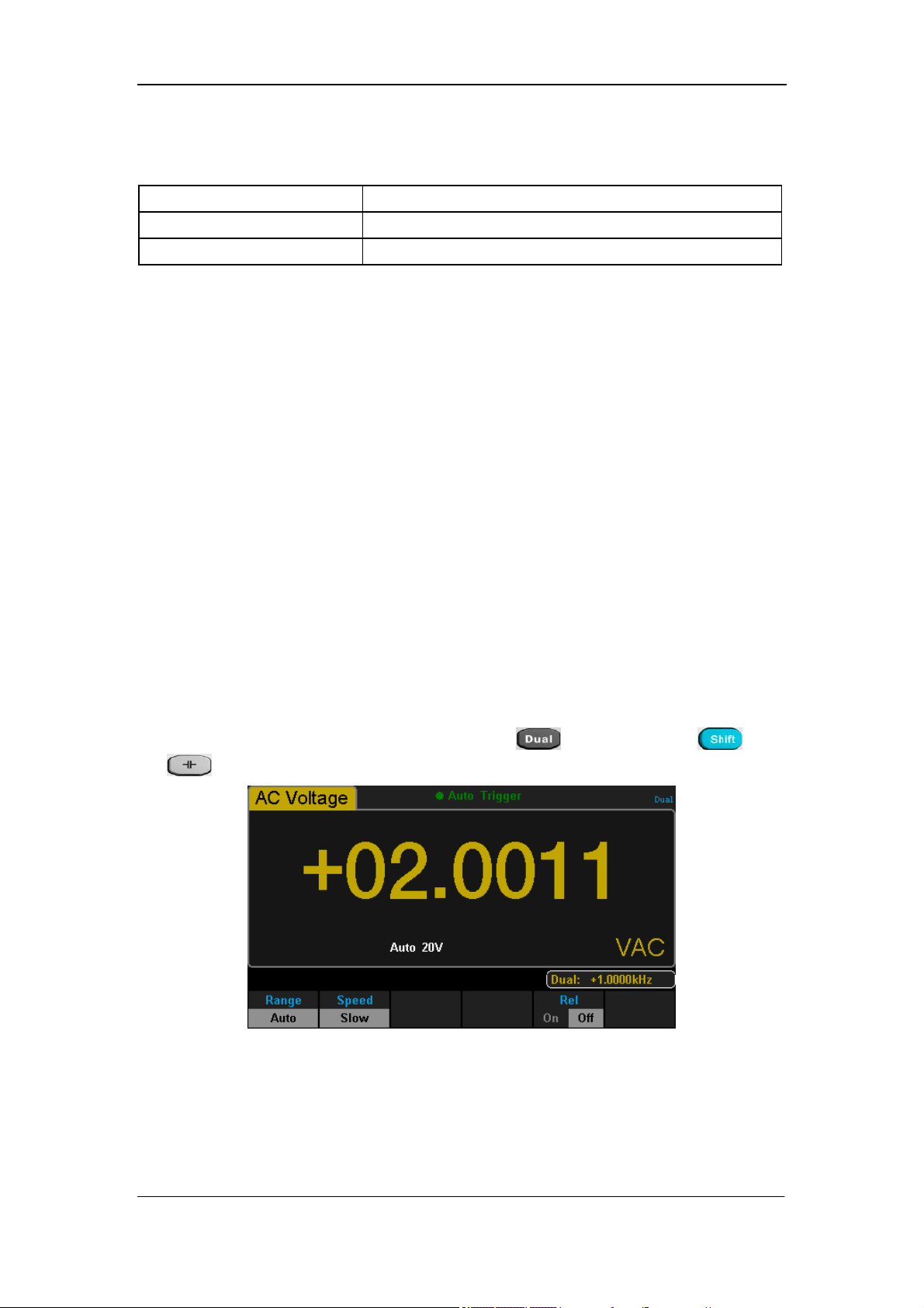
To Measure AC Voltage
The Multimeter enables to measure AC Voltage up to 750V. The method to
connect and measure DC Voltage will be introduced in details as the following
steps.
Operating Steps:
1. Press on the front panel to enter the AC Voltage measurement
interface, as shown in Diagram 2- 8.
Diagram 2- 8 AC Voltage Measurement Interface
2. Connect the red lead to terminal Input-HI and black lead to terminal
Input-LO as the following diagram.
Diagram 2- 9 Sketch Map for Measuring AC Voltage
SIGLENT
18 SDM3055 Digital Multimeter
3. Choose a proper voltage range according to the measured circuit.
Table 2- 3 Measurement Characteristics of AC Voltage
Ranges*
200mV、2V、20V、200V、750V
Input Protection
750Vrms on all ranges(HI terminal)
Configurable
Range, Rel
NOTE*:
All the ranges enable to obtain 20% value higher than original except
750V. Besides, both Manual and Auto are available for setting every
range.
When inputting range is higher than 750V at 750V Level, “overload” will be
shown on the screen.
750V input protection exists in every range.
4. Set relative value (Optional operation).
Press【Rel】to open or close Relative math function. When it is opened, the
reading displayed is a relative value which comes from the result of actual
measurement value subtracts the value that has been set. (Please refer to
“ Math Functions” in Chapter 2 to know about the details.)
5. Read measurement result.
Select required measurement rate (reading rate) by pressing 【Speed】and
read the measurement result. If you press and then press and
to get the frequency value measured from input AC signal.
Diagram 2- 10 Dual-display
6. View history data.
There are four types of way to view historical data: “Number”, “Bar
Meter” ”Trend Chart” and “Histogram”.
SIGLENT
SDM3055 Digital Multimeter 19
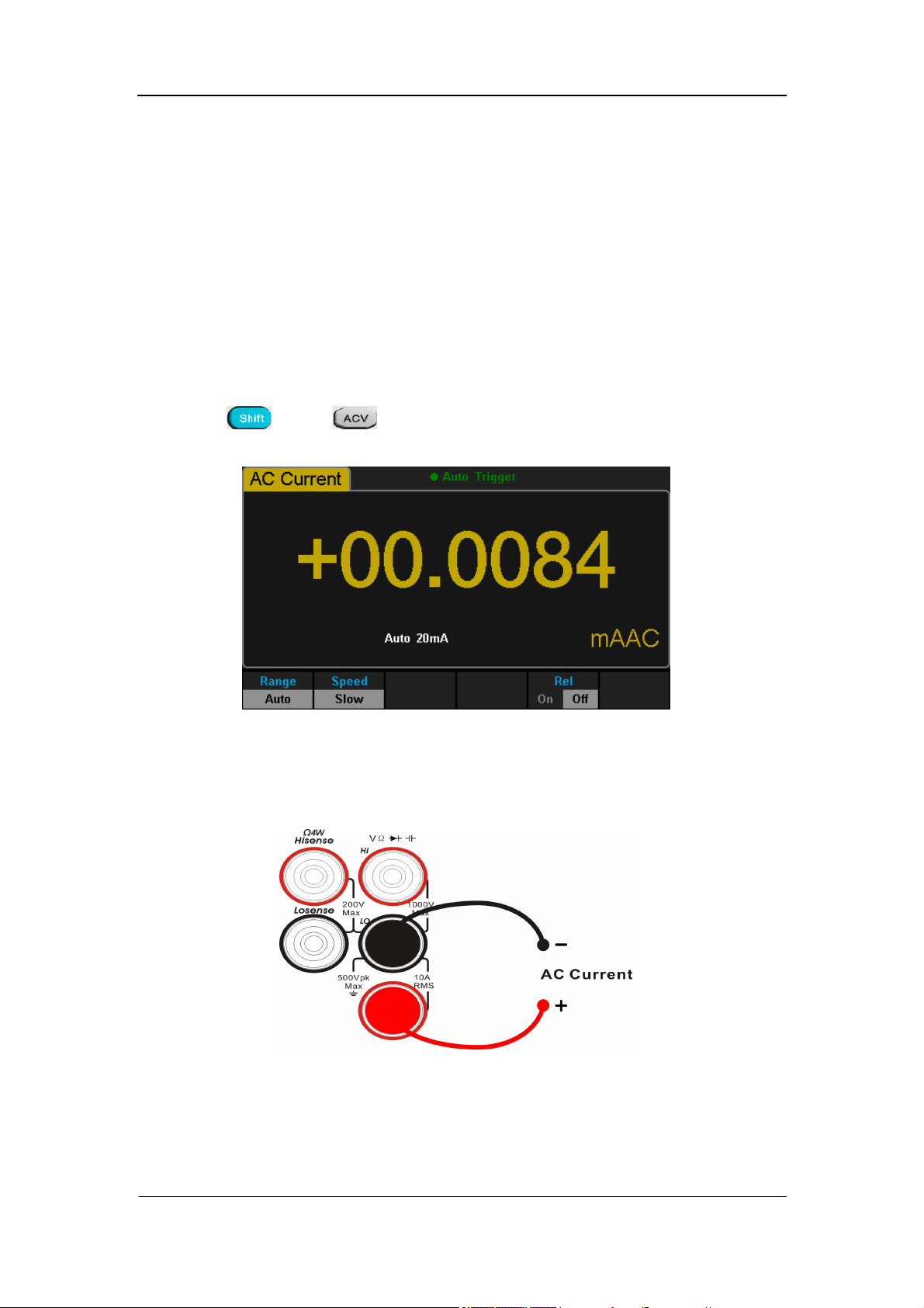
To Measure AC Current
The Multimeter enables to measure AC Current up to 10A. The method to
connect and measure AC Current will be introduced in details as the following
steps.
Operating Steps:
1. Press and on the front panel to enter the AC Current
measurement interface, as shown in Diagram 2- 11.
Diagram 2- 11 AC Voltage Measurement Interface
2. Connect the red lead to terminal Input-I and black lead to terminal
Input-LO as the following diagram.
Diagram 2- 12 Sketch Map for Measuring AC Current

SIGLENT
20 SDM3055 Digital Multimeter
3. Choose a proper current range according to the measured circuit.
Table 2- 4 Measurement Characteristics of AC Current
Ranges*
200μA、2mA、20mA、200mA、2A、10A
Input Protection
10A(back panel), 250V(fuse), 12A(inside the
instrument)
Configurable
Range, Rel
NOTE*:
All the ranges enable to obtain 20% value higher than original except 10A.
Besides, both Manual and Auto are available for setting every range.
4. Set relative value (Optional operation).
Press 【Rel】to open or close Relative math function. When it is opened, the
reading displayed is a relative value which comes from the result of actual
measurement value subtracts the value that has been set. (Please refer to
“ Math Functions” in Chapter 2 to know about the details.)
5. Read measurement result.
Select required measurement rate (reading rate) by pressing 【Speed】
and read the measurement result.
6. View history data.
There are four types of way to view historical data: “Number”, “Bar
Meter” ”Trend Chart” and “Histogram”.
SIGLENT
SDM3055 Digital Multimeter 21
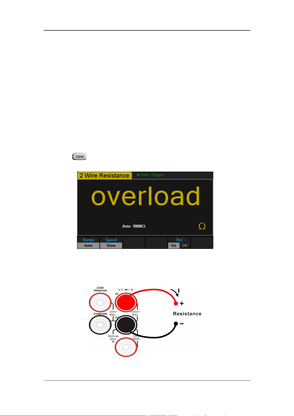
To Measure 2-Wire/4-Wire Resistance
The Multimeter enables to measure 2-Wire Resistance and 4-Wire Resistance.
The method to connect and measure 2-Wire/4-Wire Resistance will be
introduced in details separately.
2-Wire Resistance
Operating Steps:
1. Press on the front panel to enter the 2-Wire Resistance
measurement interface, as shown in Diagram 2- 13.
Diagram 2- 13 2-Wire Resistance Measurement Interface
2. Connect the red lead to terminal Input-HI and black lead to terminal
Input-LO as the following diagram.
Diagram 2- 14 Sketch Map for Measuring 2-Wire Resistance
SIGLENT
22 SDM3055 Digital Multimeter
3. Choose a proper resistance range according to the scope.
Table 2- 5 Measurement Characteristics of 2-Wire Resistance
Ranges*
200μA、2mA、20mA、200mA、2A、10A
Open-circuit Voltage <8V
Input Protection 1000V on every range (HI terminal)
Configurable
Range, Rel
NOTE*:
All the ranges enable to obtain 20% value higher than original. Besides, both
Manual and Auto are available for setting every range.
4. Set relative value (Optional operation).
Press 【Rel】to open or close Relative math function. When it is opened, the
reading displayed is a relative value which comes from the result of actual
measurement value subtracts the value that has been set. (Please refer to
“ Math Functions” in Chapter 2 to know about the details.)
5. Read measurement result.
Select required measurement rate (reading rate) by pressing 【Speed】
and read the measurement result.
6. View history data.
There are four types of way to view historical data: “Number”, “Bar
Meter” ”Trend Chart” and “Histogram”.
NOTE:
You are suggested to make use of Relative function when measuring small
resistance to reduce or escape impedance error from Test leads.
SIGLENT
SDM3055 Digital Multimeter 23
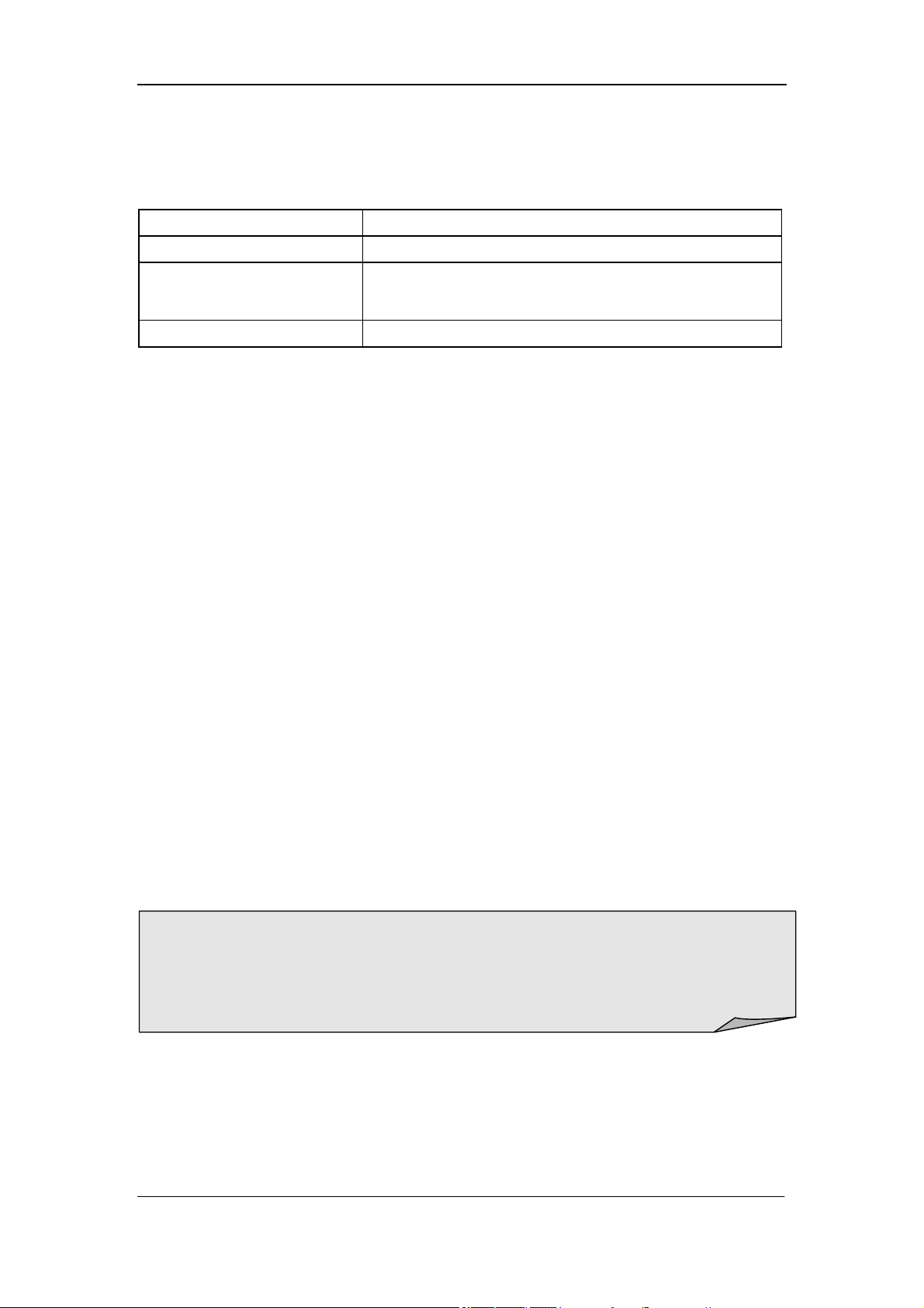
4-Wire Resistance
Operating Steps:
1. Press and on the front panel to enter the 4-Wire Resistance
measurement interface, as shown in Diagram 2- 14.
Diagram 2- 15 4-Wire Resistance Measurement Interface
2. Connect the red lead to terminal Input-HI and black lead to terminal
Input-LO as the following diagram.
Diagram 2- 16 Sketch Map for Measuring 4-Wire Resistance
SIGLENT
24 SDM3055 Digital Multimeter
3. Choose a proper resistance range according to the scope.
Table 2- 6 Measurement Characteristics of 4-Wire Resistance
Ranges*
200Ω、2kΩ、20kΩ、200kΩ、2MΩ、10MΩ、100MΩ
Open-circuit Voltage <8V
Input Protection
(1)
1000V on each range (HI terminal)
(2)
200V on each range (HI Sense, LO Sense)
Configurable Parameters Range, Rel
NOTE*:
All the ranges enable to obtain 20% value higher than original. Besides, both
Manual and Auto are available for setting every range.
4. Set relative value (Optional operation).
Press 【Rel】to open or close Relative math function. When it is open, the
reading displayed is a relative value which comes from the result of actual
measurement value subtracts the value that has been set. (Please refer to
“ Math Functions” in Chapter 2 to know about the details.)
5. Read measurement result.
Select required measurement rate (reading rate) by pressing 【Speed】
and read the measurement result.
6. View history data.
There are four types of way to view historical data: “Number”, “Bar
Meter” ”Trend Chart” and “Histogram”.
NOTE:
Please do not put the terminals of the resistance on the conductive plane or
in your hand to avoid error. The bigger of the resistance, the more affection it
will be brought.
SIGLENT
SDM3055 Digital Multimeter 25
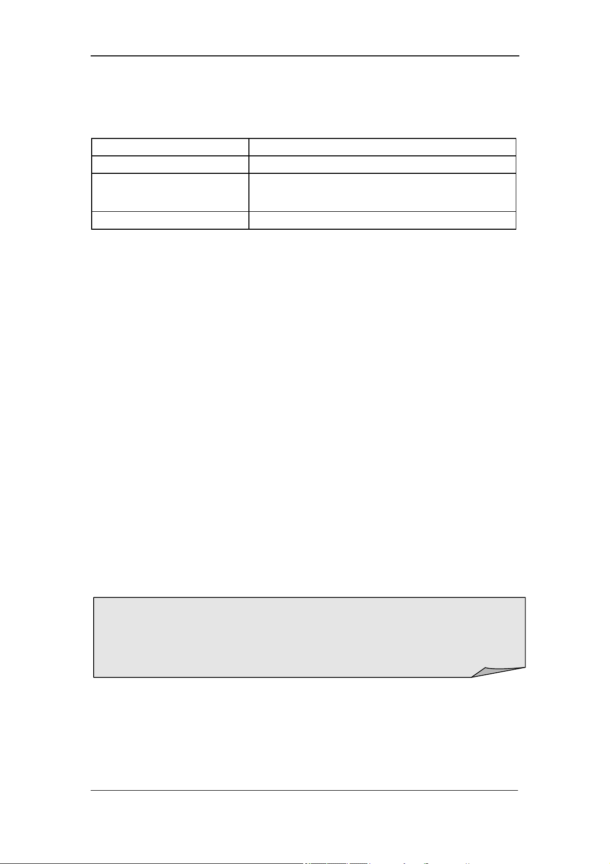
To Measure Capacitance
The Multimeter enables to measure Capacitance up to 1000μF. The method to
connect and measure Capacitance will be introduced in details as the following
steps.
Operating Steps:
1. Press on the front panel to enter the Capacitance measurement
interface, as shown in Diagram 2- 16.
Diagram 2- 17 Capacitance Measurement Interface
2. Connect the red lead to terminal Input-HI and black lead to terminal
Input-LO as the following diagram.
Diagram 2- 18 Sketch Map for Measuring Capacitance
SIGLENT
26 SDM3055 Digital Multimeter
3. Choose a proper capacitance range according to the measured circuit.
Table 2- 7 Measurement Characteristics of Capacitance
Ranges*
2nF、20nF、200nF、2μF、200μF、200μF、10000μF
Input Protection 1000V on all ranges (HI terminal)
Configurable Parameters Range, Rel
NOTE*:
All the ranges enable to obtain 20% value higher than original. Besides, both
Manual and Auto are available for setting every range.
4. Set relative value (Optional operation).
Press 【Rel】to open or close Relative math function. When it is opened, the
reading displayed is a relative value which comes from the result of actual
measurement value subtracts the value that has been set. (Please refer to
“ Math Functions” in Chapter 2 to know about the details.)
5. Read measurement result.
Capacitance measurement is fixed at “Slow” rate. Therefore, you can’t
adjust the reading rate when reading the result.
6. View history data.
There are four types of way to view historical data: “Number”, “Bar
Meter” ”Trend Chart” and “Histogram”.
NOTE:
Before measuring the electrolytic capacitance, you should make the two legs
of the electrolytic capacitance short circuit and let it be discharged.
SIGLENT
SDM3055 Digital Multimeter 27
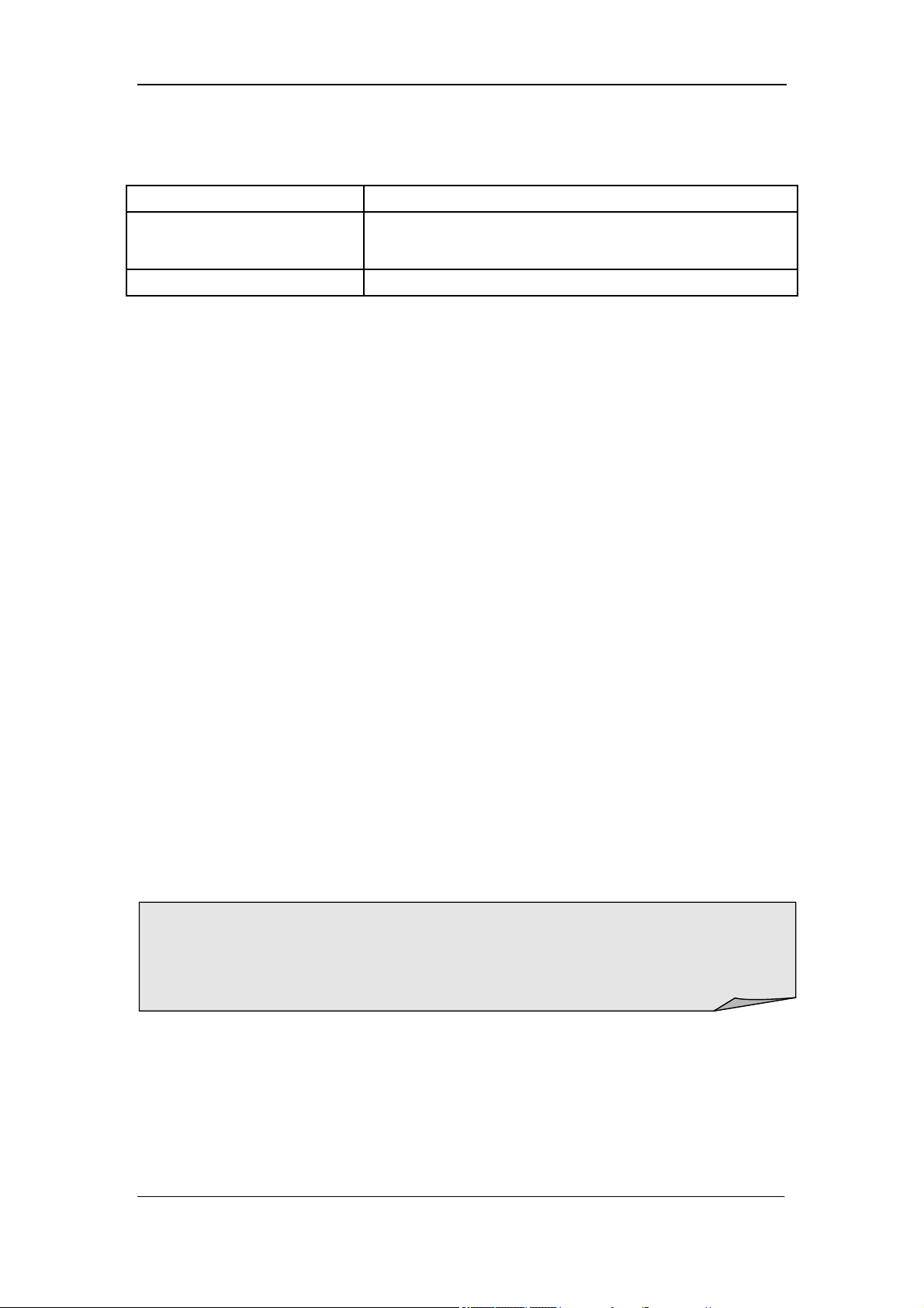
To Measure Frequency or Period
The Frequency or Period of a signal could be obtained by Dual-display
Function during measuring its voltage or current or by the function button on
the front panel. The method to connect and measure Frequency or Period will
be introduced in details as the following steps.
To Measure Frequency
Operating Steps:
1. Press and on the front panel to enter the Frequency
measurement interface. The lower right corner of the screen shows the
unit of Frequency, as shown in Diagram 2- 17.
Diagram 2- 19 Frequency Measurement Interface
2. Connect the red lead to terminal Input-HI and black lead to terminal
Input-LO as the following diagram.
Diagram 2- 20 Sketch Map for Measuring Frequency

SIGLENT
28 SDM3055 Digital Multimeter
3. Choose a proper voltage range according to the measured circuit.
Table 2- 8 Measurement Characteristics of Frequency
Ranges 200mV, 2V, 20V, 200V, 750V
Measurement Range 20Hz ~ 1MHz
Input Protection 750Vrms on all ranges (HI terminal)
Configurable Rel
4. Set relative value (Optional operation).
Press 【Rel】to open or close Relative math function. When it is opened, the
reading displayed is a relative value which comes from the result of actual
measurement value subtracts the value that has been set. (Please refer to
“ Math Functions” in Chapter 2 to know about the details.)
5. Read measurement result.
Frequency measurement is fixed at “Slow” rate. Therefore, you can’t adjust
the reading rate while reading the result.
6. View history data.
There are four types of way to view historical data: “Number”, “Bar
Meter” ”Trend Chart” and “Histogram”.
SIGLENT
SDM3055 Digital Multimeter 29
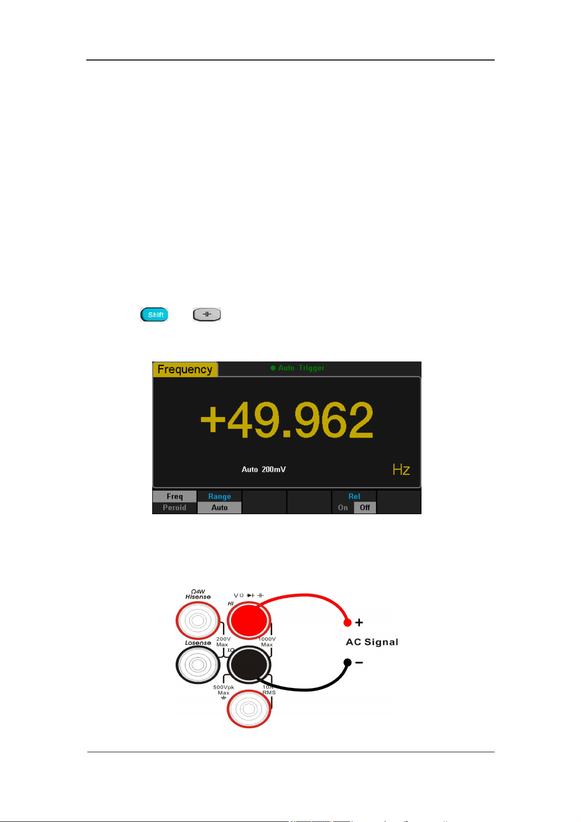
To Measure Period
Operating Steps:
1. Press and on the front panel and select 【Period】to enter
the Period measurement interface. The lower right corner of the screen
shows the unit of Period, as shown in Diagram 2- 21.
Diagram 2- 21 Period Measurement Interface
2. Connect the red lead to terminal Input-HI and black lead to terminal
Input-LO as the following diagram.
Diagram 2- 22 Sketch Map for Measuring Period
3. Choose a proper voltage range according to the measured circuit.
Table 2- 9 Measurement Characteristics of Period
Ranges 200mV, 2V, 20V, 200V, 750V
Measurement Range 20Hz ~ 1MHz
Input Protection 750Vrms on all ranges (HI terminal)
Configurable Rel

SIGLENT
30 SDM3055 Digital Multimeter
4. Set relative value (Optional operation).
Press 【Rel】to open or close Relative math function. When it is open, the
reading displayed is a relative value which comes from the result of actual
measurement value subtracts the value that has been set. (Please refer to
“ Math Functions” in Chapter 2 to know about the details.)
5. Read measurement result.
Period measurement is fixed at “Slow” rate. Therefore, you can’t adjust the
reading rate while reading the result.
6. View history data.
There are four types of way to view historical data: “Number”, “Bar
Meter” ”Trend Chart” and “Histogram”.
SIGLENT
SDM3055 Digital Multimeter 31
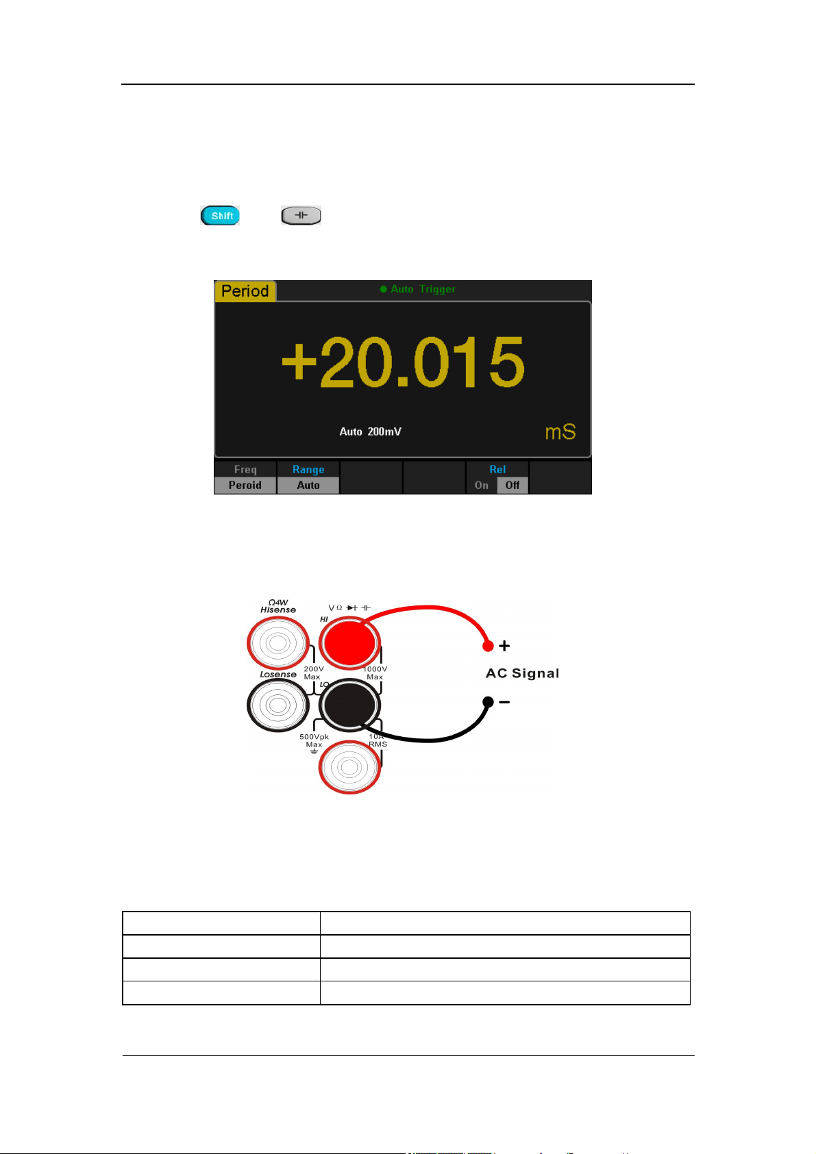
To Test Continuity
Continuity test uses double leads method to measure the resistance of the
measured circuit via about 0.5mA current. When the measured resistance in
circuit is lower than the selected one, it is considered being connected with
instrument. The method to test Continuity will be introduced in details as the
following steps.
Operating Steps:
1. Press on the front panel to enter the Continuity test interface, as
shown in Diagram 2- 23.
Diagram 2- 23 Continuity Measurement Interface
2. Connect the red lead to terminal Input-HI and black lead to terminal
Input-LO as the following diagram.
Diagram 2- 24 Sketch Map for Testing Continuity
SIGLENT
32 SDM3055 Digital Multimeter
3. Set the Short-circuit resistance.
The default value is set as 50Ω before leaving factory. The value can be
changed by using direction keys. You also can execute the Continuity
measurement directly without modification.
Table 2- 10 Measurement Characteristics of Continuity
Test Current 1mA
Ranges* Fixed at 2kΩ
Open-circuit Voltage <8V
Input Protection 1000V on all ranges (HI terminal)
Beep Condition
0≤R
testing
≤Short-circuit impedance
1Ω≤Short-circuit impedance≤2kΩ
4. Set the Beeper function.
Press 【Beeper】to turn on or off the Beeper. If the circuit is continuous, the
instrument will beep once when the Beeper is turned on.
5. Search for the test point and read measurement result.
NOTE:
Before testing continuity, please cut off the power and discharge all the
high-voltage containers to avoid damages to the Multimeter.
SIGLENT
SDM3055 Digital Multimeter 33
To Test Diode
If input voltage is under +0.7V (about 1.4kΩ), the Beeper will beep one time. If
input voltage is under 50mV (about 100Ω) the Beeper will beep persistently.
The method to test Diode will be introduced in details as the following steps.
Operating Steps:
1. Press and on the front panel to enter the Diode test
interface, as shown in Diagram 2- 25.
Diagram 2- 25 Diode Test Interface
2. Connect red lead to both terminal Input-HI and anode of the Diode and
black lead to both terminal Input-LO and cathode of the Diode as the
following diagram.
Diagram 2- 26 Sketch Map for testing Diode
SIGLENT
34 SDM3055 Digital Multimeter
3. Set the Beeper function.
Press 【Beeper】to turn on or off the Beeper. If the circuit is continuous, the
nstrument will beep once when the Beeper is turned on.
Table 2- 11 Characteristics of Checking Diodes
Test Current 1mA
Ranges* Fixed at 2V
Open-circuit Voltage <8V
Input Protection 1000V (HI terminal)
Beep Condition
0.1V≤V measured≤2.0V
4. Read measurement result.
5. Reverse the probes and measure the voltage in the diode once more.
Evaluate the diode according to the following rules:
If the Multimeter shows “overload” when in reverse bias model, it indicates
that the diode is normal.
If the Multimeter shows voltage about 0V and the instrument beeps
persistently when in forward and reverse bias model, it indicates that the
diode is short.
If the Multimeter shows “overload” when in forward and reverse model, it
indicates that the diode is open.
Note:
Before testing diode, please cut off the power and discharge all the
high-voltage containers to avoid damages to the Multimeter.
SIGLENT
SDM3055 Digital Multimeter 35
To Measure Temperature
The Multimeter supports for two types of temperature sensor: TC and RTD.
The method to connect and measure Temperature will be introduced in details
as the following steps.
Operating Steps:
1. Press on the front panel to enter the Temperature measurement
interface, as shown in Diagram 2- 27.
Diagram 2- 27 Temperature Measurement Interface
2. Connect the red lead to terminal Input-HI and black lead to terminal
Input-LO as the following diagram.
Diagram 2- 28 Sketch Map for Measuring Temperature
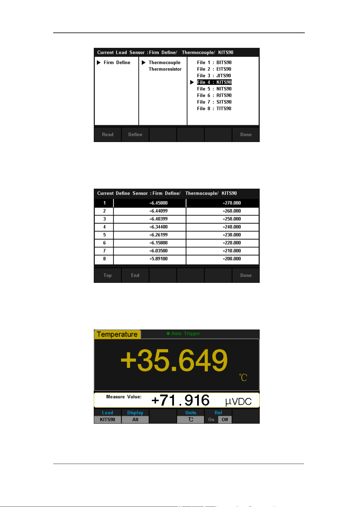
3. Press 【Load】and use direction keys to select the required file. Then
press 【Read】to recall an existing configuration file.
SIGLENT
36 SDM3055 Digital Multimeter
Diagram 2- 29 Load a Configuration File
4. Press 【Define】to view the configuration, as shown in the following
diagram:
Diagram 2- 30 Configuration of the Sensor
5. Press 【Display】to choose a display mode. The Multimeter supports three
display modes: Temperature Value, Measured Value and All.
Diagram 2- 31 Choose Display Mode of Temperature Measurement
SIGLENT
SDM3055 Digital Multimeter 37
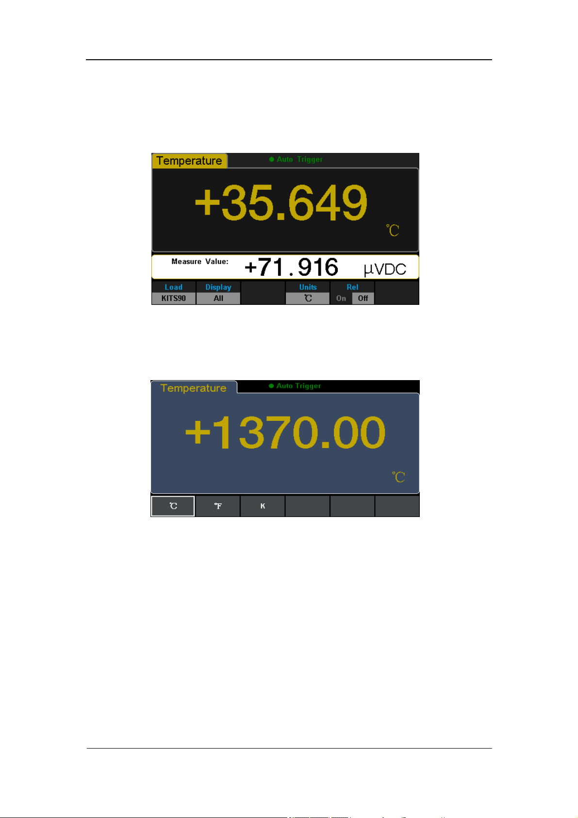
Press 【All】, the measured value will be shown on the Vice display and
the corresponding value will be shown on the Main display at the same
time, which is convenient for users to observe temperature and voltage
values.
Diagram 2- 32 Show Temperature And Voltage Values
6. Press 【Units】to choose the unit of temperature. The Multimeter supports
three units: °C 、 °F 、 K.
Diagram 2- 33 Unit Selection Interface
7. Set relative value (Optional operation).
Press 【Rel】to open or close Relative math function. When it is opened,
the reading displayed is a relative value which comes from the result of
actual measurement value subtracts the value that has been set. (Please
refer to “ Math Functions” in Chapter 2 to know about the details.)
SIGLENT
38 SDM3055 Digital Multimeter
Measurement Parameters
The parameters have been configured before the Multimeter leaving factory.
Users can either measure directly or modify them to meet your own
requirements.
AC Filter
AC Filter is applicable for DC Voltage and DC Current measurement. When
DC Voltage or DC Current function is selected, press 【Filter】 to open the filter,
as shown in the following diagram. If AC component existing in inputted DC
signal, it can be filtered by AC Filter so as to make the data more exactly.
Diagram 2- 34 Turn on or off AC Filter
SIGLENT
SDM3055 Digital Multimeter 39
DC Input Impedance
DC input impedance is only applicable for DC voltage measurement. When DC
Voltage function is selected, press【Range】 and select 【200mV】 or 【2V】
to show the menu【Input Z】, as the following diagram shows.
Diagram 2- 35 Choose DC Input Impedance
The options of input impedance for DC voltage measurements are 10MΩ and
10GΩ. 10MΩ impedance is general for the Multimeter, but for 200mV and 2V
manual ranges, 10GΩ should be chosen for better result. The current selection
will be saved in nonvolatile memory.
DC input impedance selection:
While the DC input impedance is selected as 10MΩ, the input
impedance of all measurement range is 10MΩ;
While the DC input impedance is selected to 10GΩ, the input
impedance for 200mV and 2V measurement range is 10GΩ; for 20V,
200V and 1000V measurement range is kept at 10MΩ.
The default value of DC input impedance is 10MΩ; settings of DC input
impedance are stored in the nonvolatile memory.

SIGLENT
40 SDM3055 Digital Multimeter
Short-circuit Resistance
Set up the short-circuit resistance value in the short-circuit test menu. When
the measured resistance is lower than the short-circuit resistance, the circuit is
considered as connected, and the beeper sounds (if sound is turned on). The
short-circuit resistance is only applicable to the continuity test.
Operating Steps:
1. When Continuity function is selected, press【Threshold】to enter interface
as the following diagram.
Diagram 2- 36 Set Up the Short-circuit Resistance
2. Use direction keys to change the parameter values.
Press left and right directional keys to choose different digits. Each press
for the Left key, former number will be selected, vice versa. Press up and
down keys to change the current digit value. Each press for the up key,
value will be increased 1, vice versa.
Short-circuit Resistance:
The range of short-circuit resistance is 0Ω~2000Ω. The default value is
50Ω.
The value of short-circuit resistance is stored in the nonvolatile memory
and the resistance remains unchanged after the power is off.
SIGLENT
SDM3055 Digital Multimeter 41
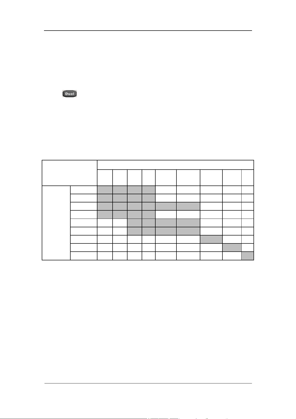
Dual-display Function
Dual-display function is used to improve test and measurement functions.
Press to open Dual-display function and the upper right corner will
show “Dual”. By this time, press a function key if this function can be used as
the vice display, it will be displayed in the Vice Display. The Main Display will
display the function that is selected before the Dual-display function is turned
on. All the available combinations are listed in table 2-12.
Table 2- 12 Available Main/Vice Function Combinations (shade is available)
Main Display Function
DCV DCI ACV ACI FREQ PERIOD
2-Wire
R
4-Wire
R
Cap
Vice
Display
Function
DCV
DCI
ACV
ACI
FREQ
PERIOD
2-Wire R
4-Wire R
Cap
Explanations:
1. If the same measurement function is used in both Main and Vice Display.
The readings in both of the display will update at the same time.
If math function (dBm, dB) is used in Main Display, when opening Vice
Display, math operation will be closed automatically and Vice Display will
show the same measurement result as Main Display.
If math function (Statistics, Limits, Relative) is used in Main Display, when
opening Vice Display, the result will still be shown in Main Display and
Vice Display will show the same measurement result as Main Display.

SIGLENT
42 SDM3055 Digital Multimeter
2. If different measurement functions are used in both Main and Vice Display.
The readings in both of the display will update alternately.
If math function (dBm, dB) is used in Main Display, when opening Vice
Display, math operation will be closed automatically and Vice Display will
show the second selected function normally.
If math function (Statistics, Limits, Relative) is used in Main Display, when
opening Vice Display, the result will still be shown in Main Display and
Vice Display will show the second selected function normally.
3. If Temperature function is used in Main Display, set the display mode
( →【Display】→【All】). Then the result (corresponding value) will
be shown in Main Display and the current measurement value is shown in
Vice Display.
4. Auto Range is adopted by Vice Display. If the same measurement function
is used in both the display, so does the range.
5. Measured data in Vice Display cannot be saved into “History”.
SIGLENT
SDM3055 Digital Multimeter 43
Utility Function
The Utility function enables users to set up system parameters, interface
parameters of the multimeters.
Press and to enter the operating menu of Utility function, as
the following diagram shows.
Diagram 2- 37 Utility Function Configuration Interface
Table 2- 13 Utility Function Menu Description
Function Menu Description
Store/Recall Store or recall setting files.
Manage File Create a new file, copy, rename or delete a file.
I/O Config Set up LAN and GPIB parameters.
Test/Admin Provide board test and firmware update function.
System Setup Set up system information configuration.
SIGLENT
44 SDM3055 Digital Multimeter
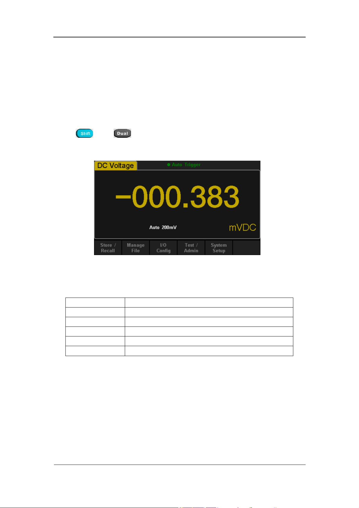
Store and Recall
The Store/Recall function enables users to store and recall the instrument
parameters and data files in the local storage as well as in USB storage.
Operating Steps:
1. After entering into the function menu of Utility, press 【Store/Recall】to
enter the interface as shown in diagram 2-38.
Diagram 2- 38 Store and Recall Interface
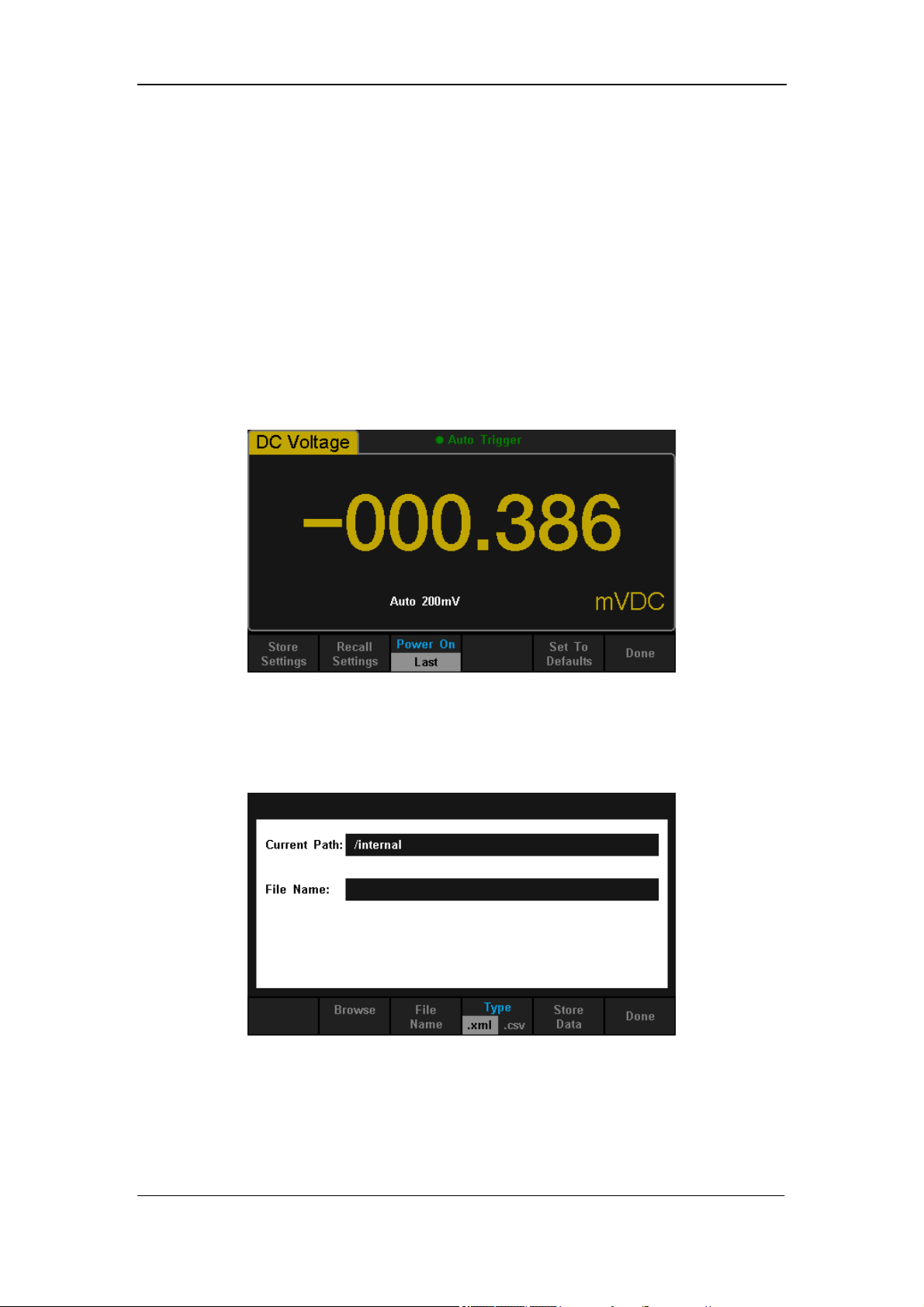
2. Press【Store Settings】to enter the following interface.
Diagram 2- 39 Store Settings Interface
SIGLENT
SDM3055 Digital Multimeter 45
Table 2- 14 Storage Function Menu Description
Function
Menu
Settings Description
Browse Choose the location that file will be saved.
File
Name
Input a file name.
Type .xml / .csv Choose the type that the file is saved.
Store
MS Data
Save the file as input file name to the current
selected location.
Done
Save all changes and return to the higher level
menu.
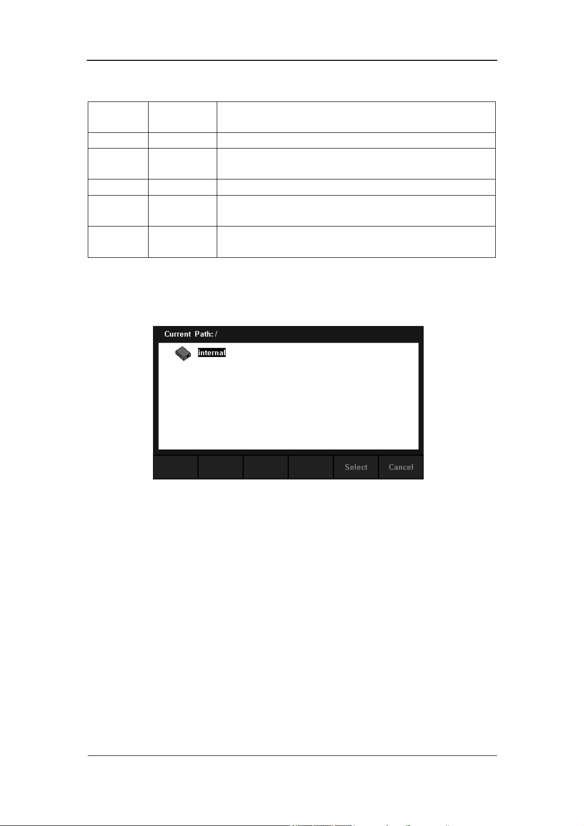
3. Press【Recall Settings】to enter the following interface. Use direction keys
to choose storage path and location, and press【Select】to recall the
corresponding file.
Diagram 2- 40 Recall Function Interface
4. Press【Power on】to set the Power On state of the instrument.
You can choose【Last】 or 【Factory Default】as the initial state when the
instrument is turned on.
The configuration is effective when you restart the Multimeter.
DC Voltage is always the selected function when the instrument is turned
on even if you have selected【Last】 or 【Factory Default】as the Power
On state.
5. Press【Set to Defaults】to select “Factory Default” as the Power On state.
SIGLENT
46 SDM3055 Digital Multimeter
Manage File
The Manage File function enables users to create a new folder and save, copy,
rename or delete files in the local storage as well as in USB storage.
Operating Steps:
1. After entering into the function menu of Utility, press【Manage File】to
enter the interface as shown in diagram 2-41.
Diagram 2- 41 Manage File Interface
2. Choose the file location.
Press【Browse】and use direction keys to select the corresponding file.
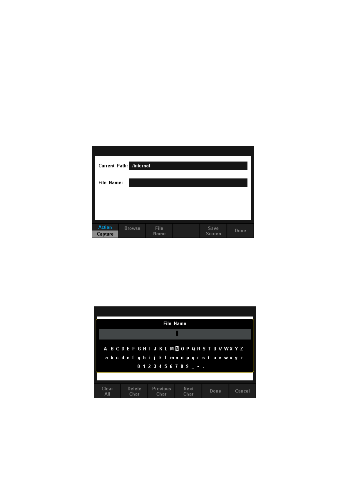
3. Press【File Name】to enter the following interface.
Diagram 2- 42 Input File Name
SIGLENT
SDM3055 Digital Multimeter 47
The method of inputting file name:
Press direction keys to select a desired char in the input area.
Press “OK” key on the front panel to input selected char in the input area.
Press【Clear All】to clear all input chars.
Press【Delete Char】to delete the letter on which the cursor taking place.
Press【Previous Char】to move the cursor in the file name area to the
previous char.
Press【Next Char】to move the cursor in the file name area to the next char.
Press【Done】to save the current file and return to the higher level menu.
Press【Cancel】to cancel the current operation and return to the higher
level menu.
4. Press【Action】and select【Folder】, 【Capture Display】, 【Copy】,
【Rename】or【Delete】to do the corresponding operation.
Table 2- 15 Action Settings
Function
Menu
Description
Folder
Press【Create Folder】to create a new folder.
Capture
Display
Press【Save Screen】to save current captured screen picture
as standard BMP format.
Copy
Press【Perform Copy】to copy the selected file.
Rename
Press【Perform Rename】to rename the selected file.
Delete
Press【Perform Delete】to delete the selected file.
Done Save all changes and return to the higher level menu.
SIGLENT
48 SDM3055 Digital Multimeter
I/O Configuration
Press【I/O Config】to enter the following interface and set up the parameters.
Diagram 2- 43 I/O Configuration Interface
LAN Settings
The Multimeter enables users to operate instrument remotely by LAN
interface and store or recall internet settings. You can look over current LAN
settings and set up IP address and subnet mask.
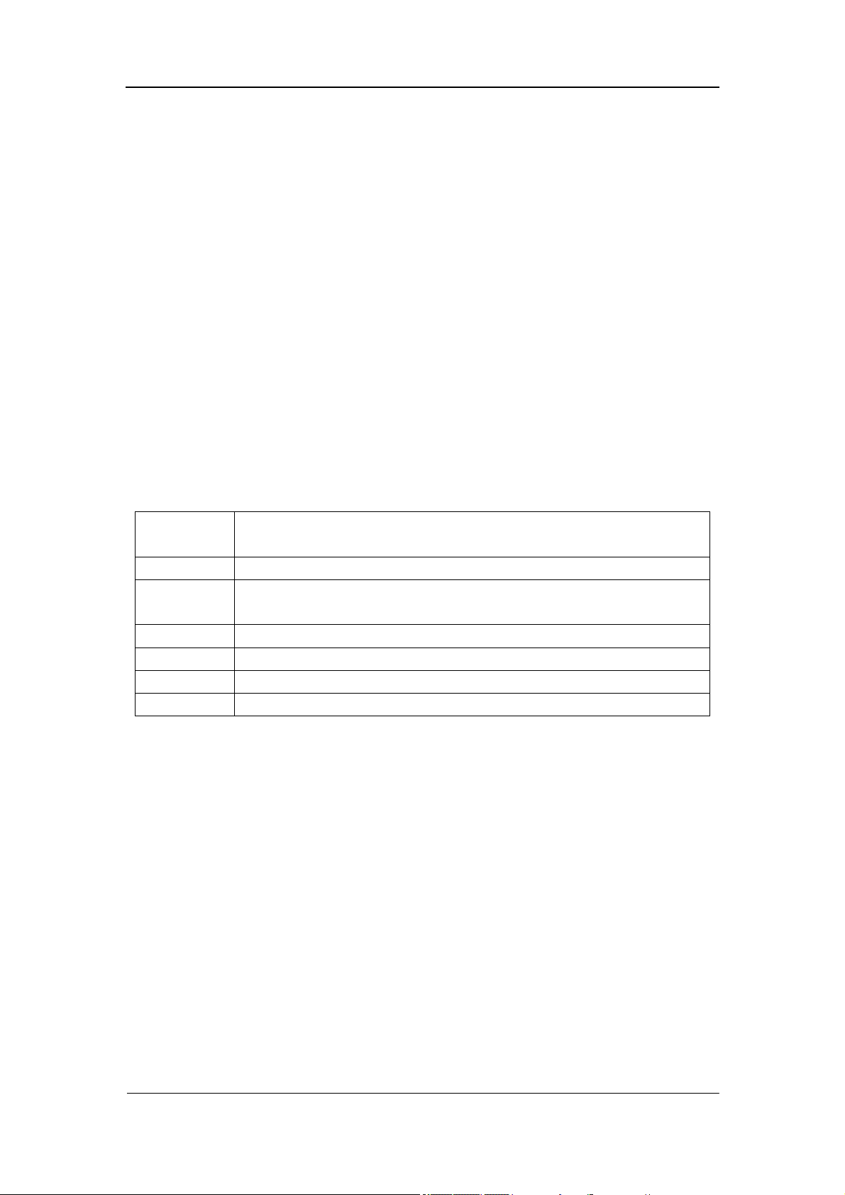
After entering into the function menu of Utility, press 【I/O Config】. Select【On】
→【LAN Settings】→【Modify Settings】to enter the following interface.
Diagram 2- 44 LAN Settings Interface
SIGLENT
SDM3055 Digital Multimeter 49
Table 2- 16 LAN Settings
Function
Menu
Description
IP Address
Set up IP address and the default setting is 10.11.11.104.
Subnet
Mask
Set up subnet mask and the default setting is 255.0.0.0.
Cancel Cancel current operation and return to the higher level menu.
Done Save all changes and return to the higher level menu.
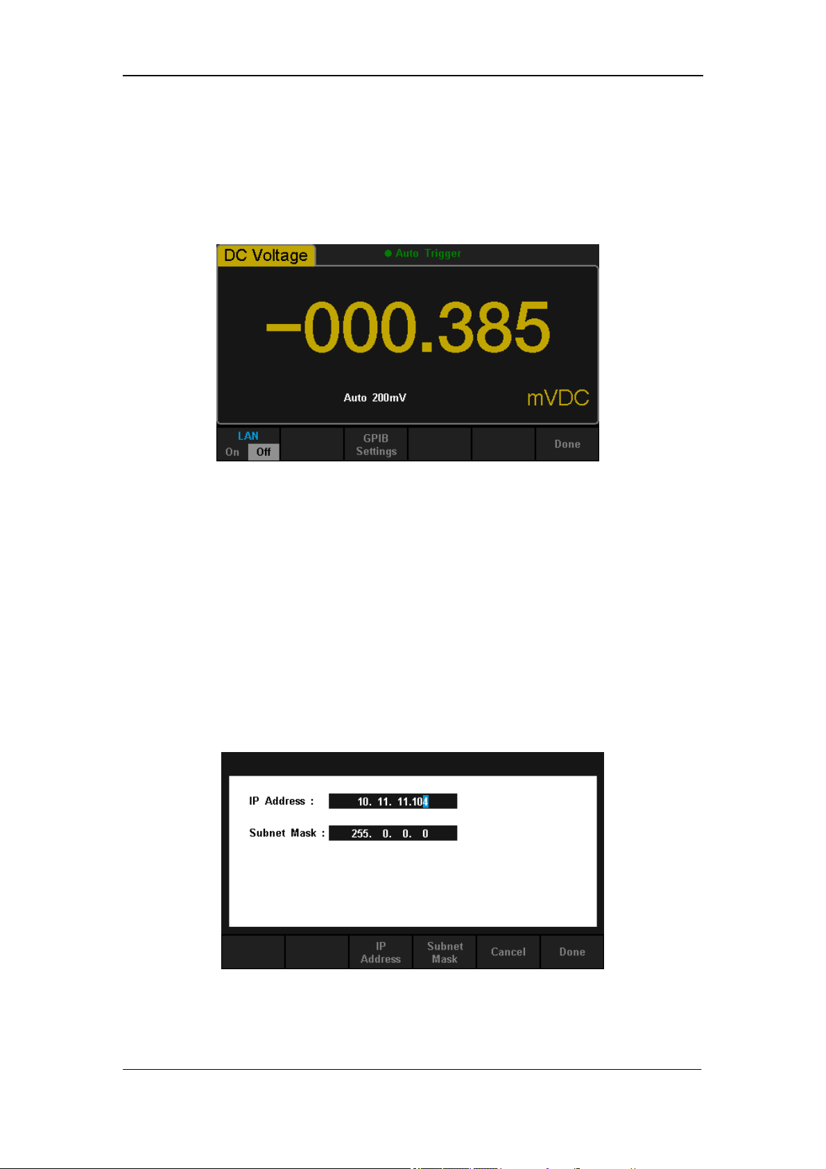
GPIB Settings (Only for SDM3055A)
Each device on the GPIB (IEEE–488) interface must have a unique address.
The default address is 30 when the instrument is leaving the factory. The
address of Multimeter can be any integral value between 1 and 30.
Operating Steps:
1. After entering into the function menu of I/O configuration, press
【GPIB Settings】to enter the interface shown in diagram 2-45.
Diagram 2- 45 GPIB Settings
2. Users can change the value of GPIB address by direction keys.
3. Press【Select】to set the input value as GPIB address and return to the
higher level menu.
SIGLENT
50 SDM3055 Digital Multimeter
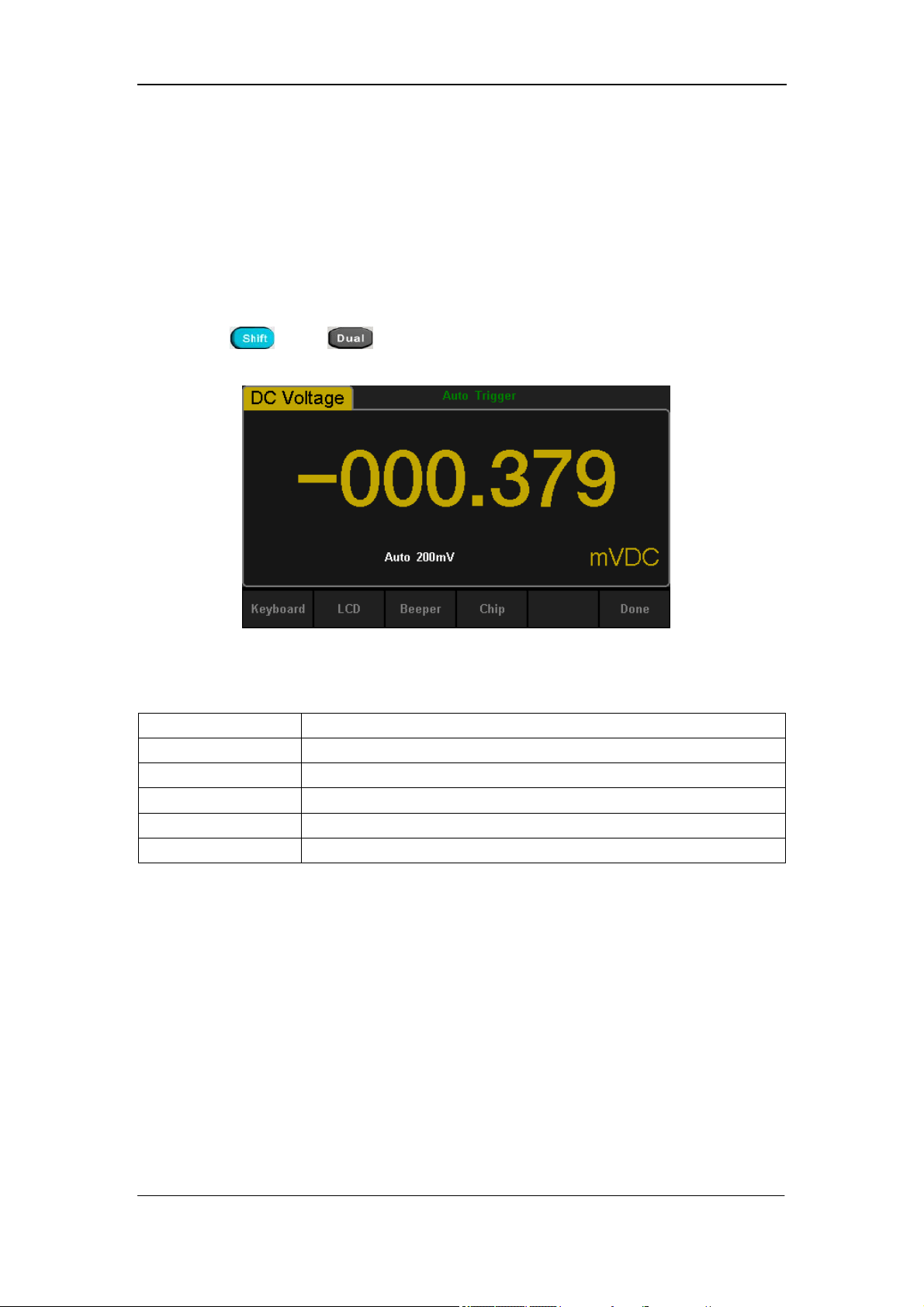
Board Test
SDM3055 provides self-test functions, including Key Test, LCD Test, Beeper
Test and Chip Test.
Operating Steps:
1. Press and , then choose【Test/Admin】→【Board Test】
to enter the following interface.
Diagram 2- 46 Board Test Interface
Table 2- 17 Board Test Function Description
Function Menu Description
Key Test the instrument’s keys.
LCD Test the instrument’s LCD screen.
Beeper Test the instrument’s beeper.
Chip Test the instrument’s chips.
Done Return the higher level menu.
2. Test the keys.
Select【Key】to enter the key test interface, as the Diagram 2-47 shows. The
on-screen lathy rectangle shapes represent the keys on the front panel. Test
all keys and knobs and you should also verify that all the backlit buttons
illuminate correctly.
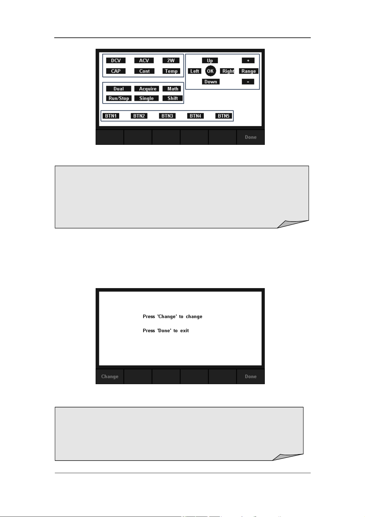
SIGLENT
SDM3055 Digital Multimeter 51
Diagram 2- 47 Key Test Interface
3. Test the LCD screen.
Select【LCD】to enter the screen test interface, the screen shows the
message:” Press ‘Change’ to change Press ‘Done’ to exit“. Press【Change】
to start the test and observe if the screen has severe color or other display
error. As the Diagram 2-48 shows.
Diagram 2- 48 LCD Test Interface
NOTE:
Before you operate, the shapes on the screen display blue color.
The corresponding area of tested buttons or knobs would display green
color.
Press【Done】to exit the test.
NOTE:
Press【Change】to change the color of the screen. There are three
colors: red, blue and green.
Press【Done】to exit the test.
SIGLENT
52 SDM3055 Digital Multimeter
4. Test the beeper.
Press 【Beeper】to test the beeper. Under regular circumstance, press
【Beeper】 one time and the instrument will beep one time.
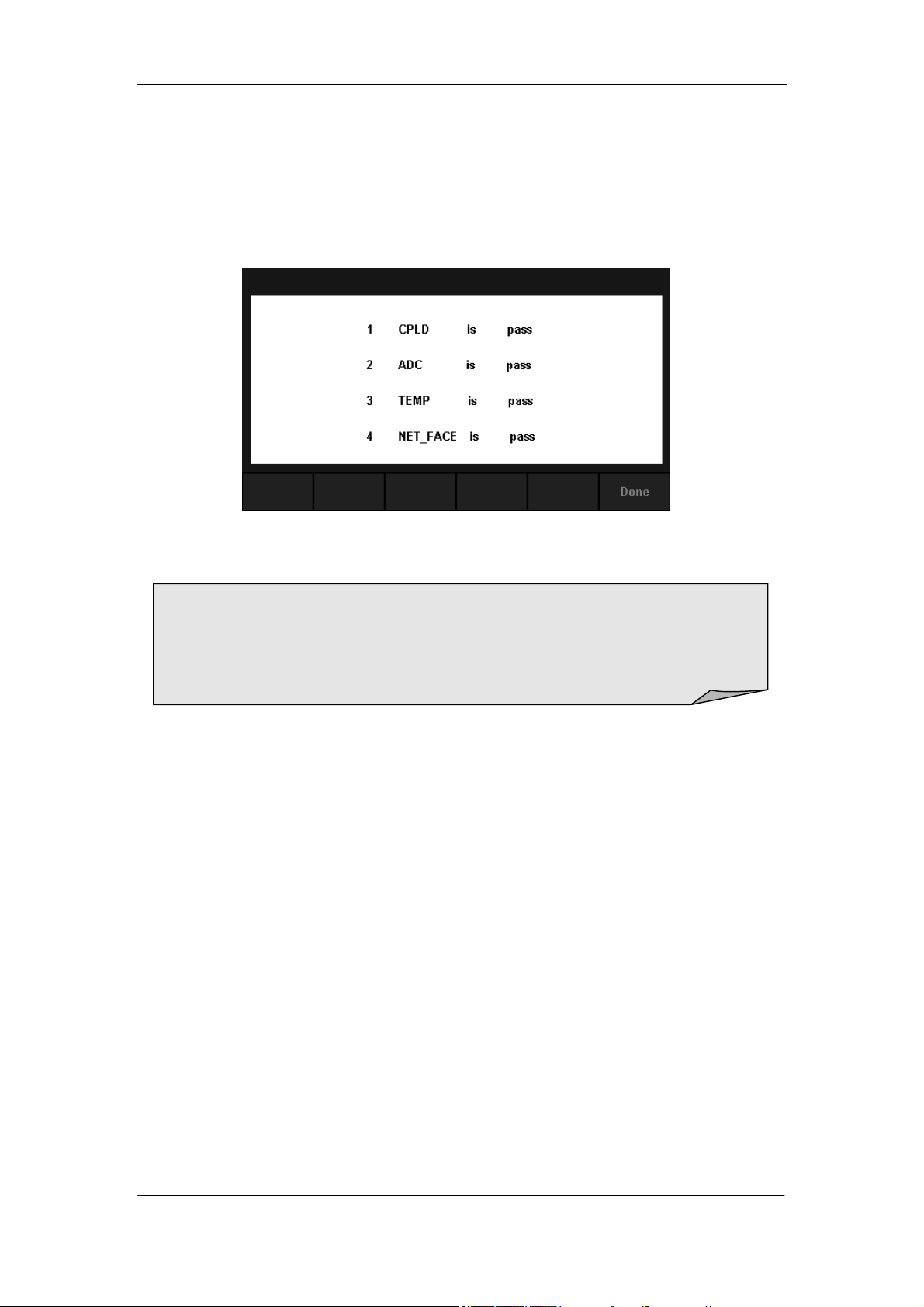
5. Test the chips.
Press【Chip】→【Start】to enter chip test interface, as Diagram 2-49 shows.
Diagram 2- 49 Chip Test Interface
6. Press【Done】to exit the board test.
NOTE:
If the test is passed, the corresponding result shows “pass”.
If the test is failed, the corresponding result shows “fail”.
SIGLENT
SDM3055 Digital Multimeter 53
Firmware Update
The software of the Multimeter can be updated directly via USB flash drive,
updating current software version to desired software version.
Operating Steps:
1. Copy the update file to the USB flash drive.
2. Insert USB flash drive to USB host interface on the front panel of the
Multimeter.
3. Press → →【Test/Admin】→【Firmware Update】, then press
【Browse】and select the update file. Next, press【Update】→【Yes】to
start updating the system software.
4. After accomplishing update, the screen shows message:
” Firmware Update Done!” Then you can move the USB flash drive
away.
5. Restart the Multimeter and check the version information.
Press → →【System Setup】→【System Info】to check if
the software and hardware version after updating is in accordance with
the desired version. If not, the updating is failed and you need update
once more as the above steps.
6. After checking, press【Done】to exit the system information interface.
NOTE:
Don’t cut off the power during the instrument is updating
SIGLENT
54 SDM3055 Digital Multimeter
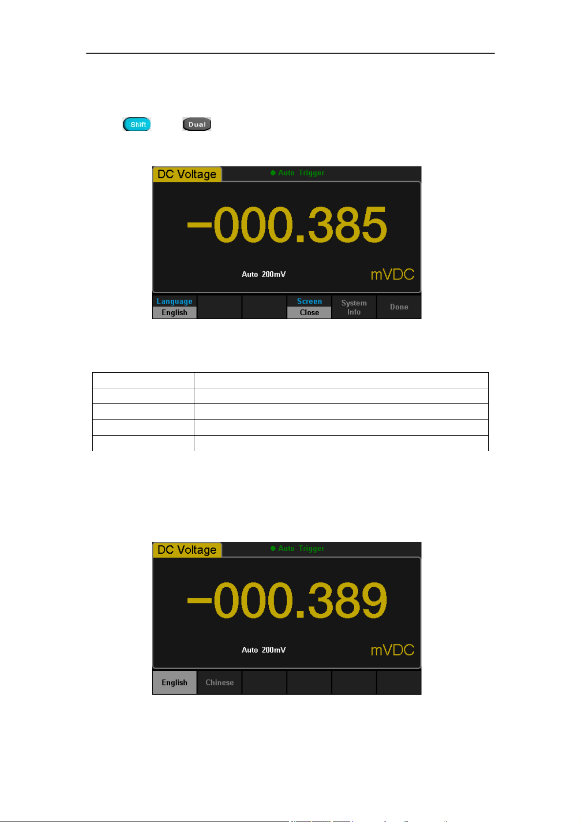
System Setup
Press and , then select【System Setup】to enter the following
interface.
Diagram 2- 51 System Setup Interface
Table 2- 18 System Settings Menu Description
Function Menu Description
Language Select the display interface language.
Screen Set up the screen protection function.
System Info View system information.
Done Return to the higher level menu.
1. Select language.
The Multimeter supports two kinds of languages, English and Chinese. Press
【Language】to enter the following interface.
Diagram 2- 52 Choose Language

SIGLENT
SDM3055 Digital Multimeter 55
2. Set up the time of screen protection.
Press【Screen】to set screen protection as 1 Min, 5 Mins, 15 Mins, 30 Mins,
1 Hour, 2 Hours or 5 Hours according to different demands. Activate the
screen saver program and screen saver will be on if no action is taken within
the time that you have selected. Press any button the resume.
3. View system information.
Press【System Info】to view system information, including startup times,
software version, hardware version, production ID and serial number, as
shown in the following diagram.
Diagram 2- 53 System Information
SIGLENT
56 SDM3055 Digital Multimeter
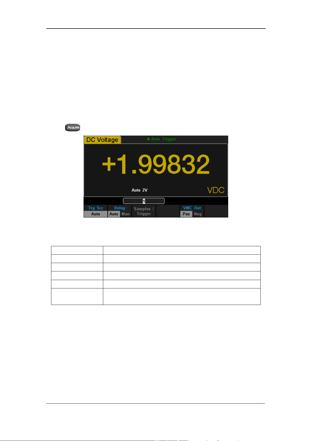
Acquire
Sampling is a process of acquiring and digitizing signal. The optional Trigger
methods of the Multimeter include Auto Trigger, Single Trigger and External
Trigger.
Press to enter the interface shown as the following diagram:
Diagram 2- 52 Acquire Interface
Table 2- 19 Function Menu of triggering parameter
Function Menu Description
Trg Src Set the source of trigger.
Slope Set the slope polarity of external trigger.
Delay Set the delay.
Samples/Trigger Set the number of samples or trigger.
VMC Out
Set the polarity of output pulse signal when sampling
signal is finished.
SIGLENT
SDM3055 Digital Multimeter 57
Auto Trigger
Auto Trigger parameters that need to be set up include delay, samples/
trigger and VMC out.
Operating Steps:
1. Press , then select 【Trg Src】→【Auto】or press on the front
panel directly to enable Auto Trigger.
2. Set the delay.
Delay is the waiting time after the trigger signal is sent out and before the
auquiring starts. Press 【Delay】to select Auto or Manual mode. When
choosing Manual mode,Left and Right keys are used to switch the
number of a numerical value, Up and Down keys are used to change the
selected value.
3. Set the number of samples or trigger.
Press 【Samples/Trigger】to set the sample count. Left and Right keys are
used to switch the number of a numerical value, Up and Down keys are
used to change the selected value.
4. Set the VMC Out.
Press 【VMC Out】to choose Positive or Negative polarity.
Sample Count
Sample Count indicates the count of point sampled while the
Multimeter getting a signal of Single Trigger.
The range of sampling point should be between 1 and 599999999.
The default value of Sample Count is 1.
SIGLENT
58 SDM3055 Digital Multimeter
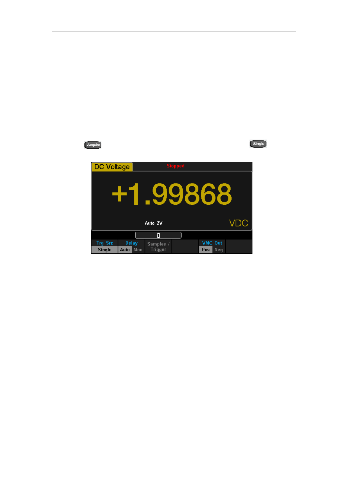
Single Trigger
Single Trigger parameters that need to be set up include delay, samples
/trigger and VMC out.
Operating Steps:
1. Press , then select 【Trg Src】→【Single】or press on the
front panel directly to enable Single Trigger. See the diagram below.
Diagram 2- 53 Setting interface of Auto Trigger
2. Set the delay.
Press 【Delay】to select Auto or Manual mode.
3. Set the number of samples or trigger.
Press 【Samples/Trigger】to set sample count.
4. Set the VMC Out.
Press 【VMC Out】to choose Positive or Negative polarity.
SIGLENT
SDM3055 Digital Multimeter 59
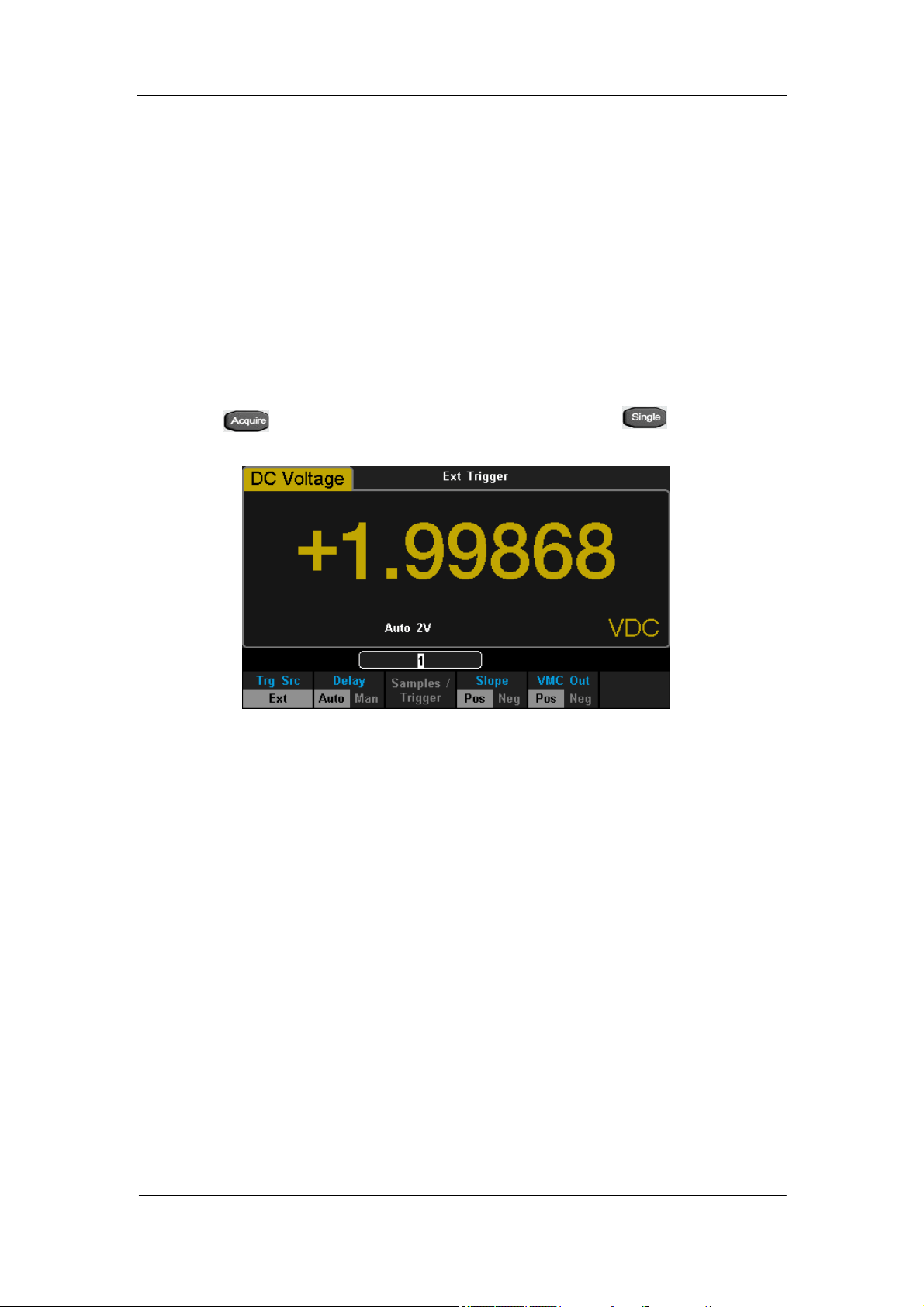
External Trigger
The external trigger signal will be input via EXT TRIG interface on the rear
panel. External trigger parameters that need to be set up include delay,
samples /trigger, slope and VMC out.
Operating Steps:
1. Press , then select 【Trg Src】→【Ext】or press on the front
panel directly to enable External Trigger.
Diagram 2- 54 Setting interface of Ext Trigger
2. Set the polarity of slope.
Press 【Slope】to choose Positive or Negative polarity.
3. Set the delay.
Press 【Delay】to choose Auto or Manual mode.
4. Set the number of samples or trigger.
Press 【Samples/Trigger】to set sample count.
5. Set the VMC Out.
In External Trigger mode, the Multimeter could output a pulse signal
through the VM COMP interface on the rear panel after sampling signal is
finished.
SIGLENT
60 SDM3055 Digital Multimeter
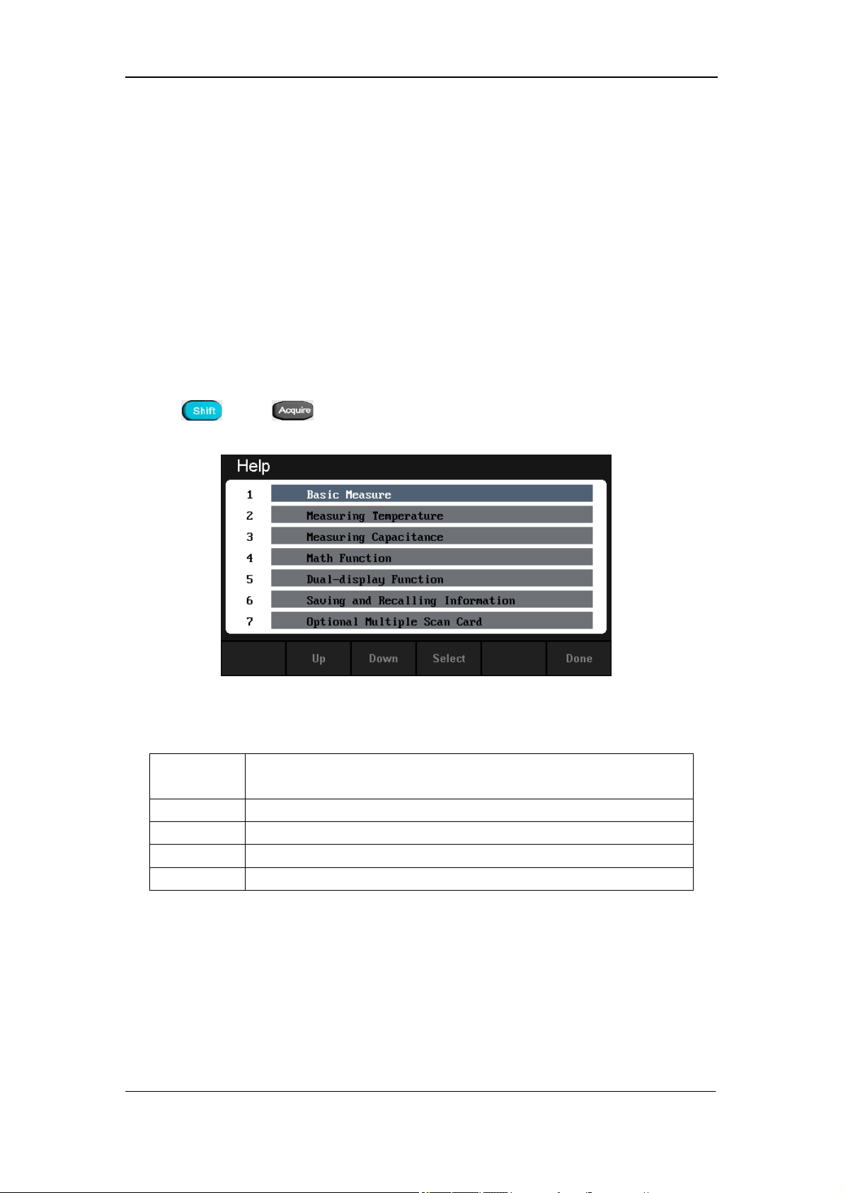
Help System
SDM3055 provides powerful built-in help system. You can recall help
information at any time during using the instrument. You also can get a
particularly help for every button on the front panel or menu softkey by using
the built-in help system. Or you can get help about familiar operations with
the help list.
Press and to enter the help list, as the following diagram
shows.
Diagram 2- 55 Help Menu
Table 2- 20 Help System Operating Menu
Function
Menu
Description
Up Move up the cursor and select the help menu.
Down Move down the cursor and select the help menu.
Select Select the help information you want and read it.
Done Return to the higher menu.
1. Basic Measure.
Get basic measurement types and methods to connect the leads in different
measurements.
2. Measuring Temperature.
Get the method to measure temperature.

SIGLENT
SDM3055 Digital Multimeter 61
3. Measuring Capacitance.
Get the method to measure temperature.
4. Math Function.
Introduce how to use the math function while you are measuring.
5. Dual-display Function.
Get the method to use the dual-display function while you are measuring.
6. Saving and Recalling Information.
Introduce how to store and recall the data/parameter/ sensors files.
7. Optional Multiple Scan Card.
Get help about operating optional multiple scan cards.
8. The convention and Tips of Softkeys.
Get help about the convention and tips of softkeys.
9. Technical Support.
Get the method to obtain technical support.
Explanation:
In the help menu interface, you also can move cursor and select the
corresponding menu by up and down direction keys and press ”OK” to
read the help information.
While reading help information, you also can look up and down the
information by up and down direction keys.
SIGLENT
62 SDM3055 Digital Multimeter
Math Function
The Multimeter provides five math functions: Statistics, Limits, dBm, dB and
Relative. Choose different math functions to meet different measurement
demands. Math functions can only be used in DC Voltage, AC Voltage, DC
Current, AC Current, Resistance, Frequency, Period and Temperature
measurement. Among these functions, dBm and dB are only used in DC
Voltage and AC Voltage measurement.
Press to show the operating menu of math functions on the screen, as
shown in the following diagram.
Diagram 2- 56 Math Function Menu of DC Voltage
Diagram 2- 57 Math Function Menu of AC Current
SIGLENT
SDM3055 Digital Multimeter 63
Table 2- 21 Math Function Menu Description
Function
Menu
Settings Description
Statistics
Reading statistic functions, including: max, min,
average, span, std dev and samples.
Limits
The Limits function performs Pass/Fail testing
according to the specified upper and lower limits.
dBm
The dBm is based on a calculation of power delivered
to a reference resistance, 0dBm = 1mW.
dB
The dB measurement is the difference between the
input signal and a stored relative value.
Rel Value
Value/Off
Turn on the relative value function and set up the
value. Or turn off the function.
Explanations:
Math function can only be applicable to the main display.
If measurement function is changed, all math functions will be
closed except Statistics.
SIGLENT
64 SDM3055 Digital Multimeter
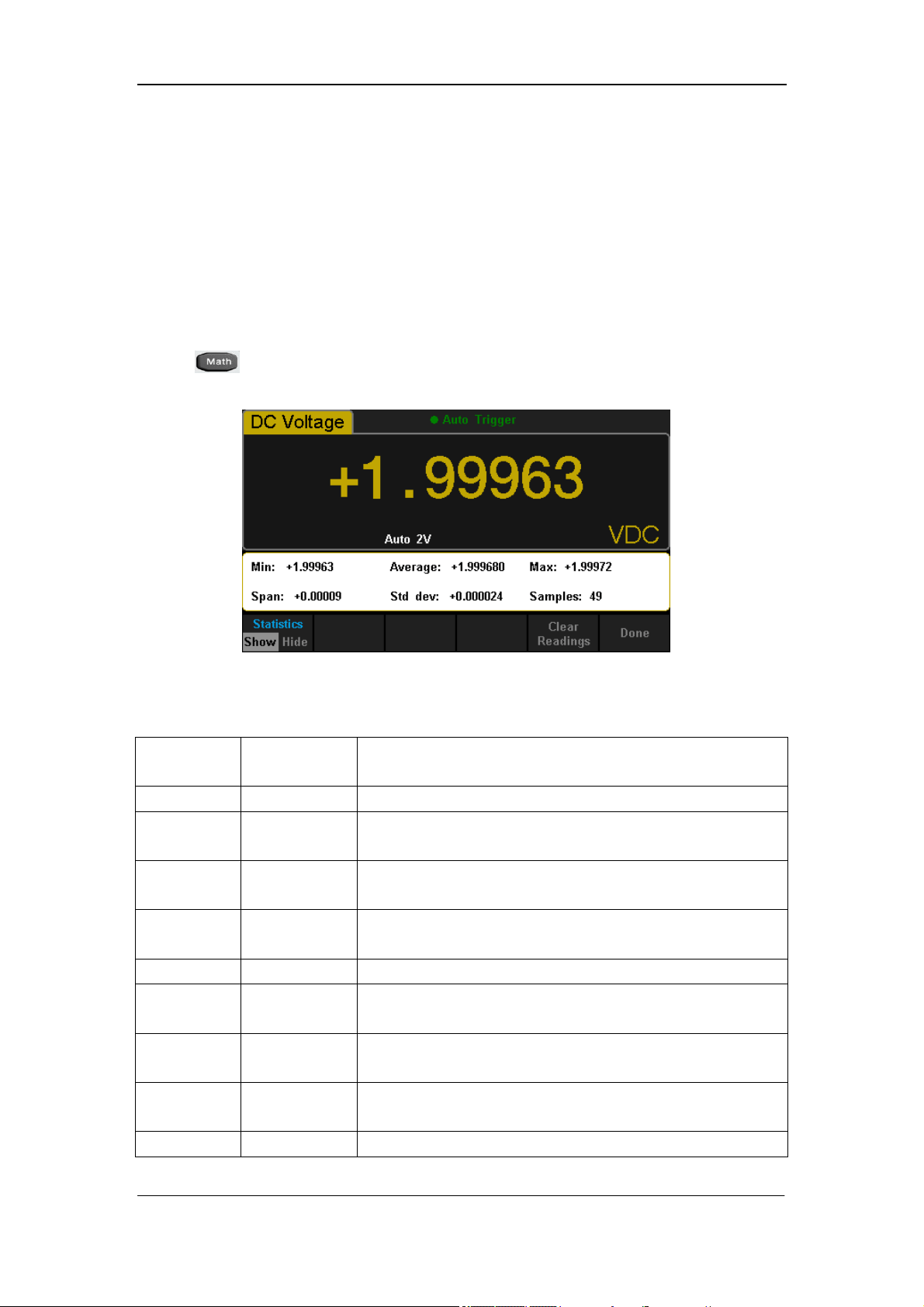
Statistics
There are many kinds of reading statistic functions, including: Max, Min,
Average, Standard deviation and so on. The Statistic function is available for
DC Voltage, AC Voltage, DC Current, AC Current, Resistance, Frequency,
Period, Capacitance and Temperature measurement.
Press →【Statistics】→【Show】 to enter the interface shown in the
following diagram.
Diagram 2- 58 Statistics
Table 2- 22 Statistic Measurement Menu Function Description
Function
Menu
Settings Description
Statistics Show/Hide Show or hide the statistics function interface.
Min
Show the minimum statistics value of current
measurement.
Average
Show the average statistics value of current
measurement.
Max
Show the maximum statistics value of current
measurement.
Span Show the span of current measurement.
Std dev
Show the std dev statistics value of current
measurement.
Samples
Show the maximum statistics value of current
measurement.
Clear
Readings
Clear all current readings and restart statistics.
Done Return to the higher level menu.

SIGLENT
SDM3055 Digital Multimeter 65
Statistics Function:
In statistic function, the first reading is usually set to the maximum or
minimum value. When getting more readings, current displaying value
is always the maximum/minimum reading among all the measured
values.
The maximum, minimum, average and reading quantities are stored in
volatile memory.
SIGLENT
66 SDM3055 Digital Multimeter
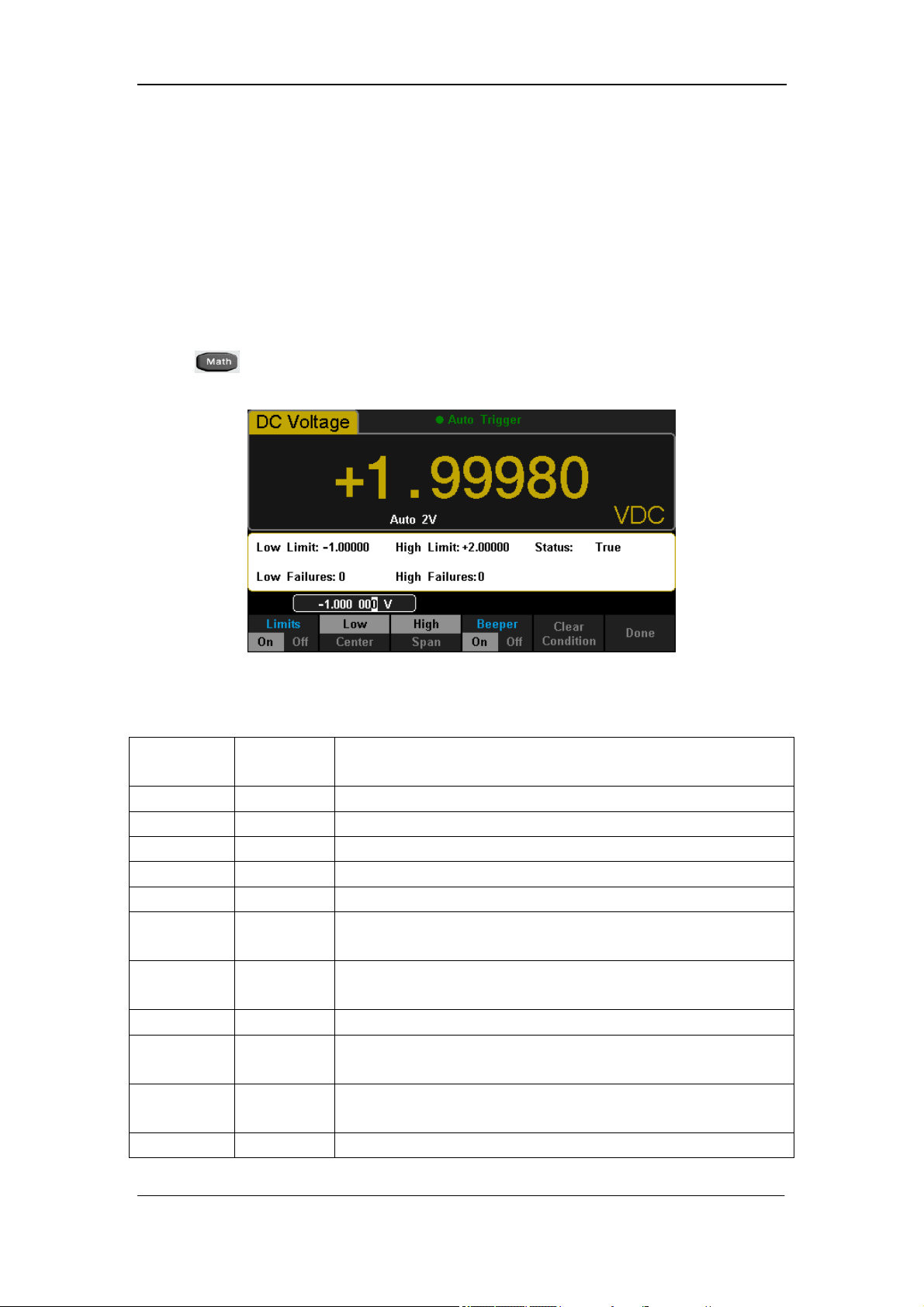
Limits
Limits function is available to prompt signals beyond ranges according to the
upper and lower parameters. Following are some measurement functions
which are able to do limit operation: DC Voltage, AC Voltage, DC Current, AC
Current, Resistance, Frequency, Period, Capacitance and Temperature.
Press →【Limits】→【On】 to enter the interface shown in the following
diagram.
Diagram 2- 59 Limits
Table 2- 23 Limits Measurement Menu Function Description
Function
Menu
Settings Description
Limits On/Off Turn on or turn off the Limits function.
Low Set the desired lower limit.
Center Set the desired center value
High Set the desired upper limit.
Status Show the status of limit test.
Low
Failures
Show the times that reading is lower than the limit.
High
Failures
Show the times that reading is higher than the limit.
Span Set the desired span.
Beeper On/Off
When the beeper is on, if the reading is lower or
higher than limits, the instrument will beep once.
Clear
Condition
Clear all current readings and restart to test.
Done Save all changes and return to the higher level menu.

SIGLENT
SDM3055 Digital Multimeter 67
1. How to Set Limits
Select 【High】,【Low】,【Center】or【Span】 and then switch to the needed
digit by Left or Right Direction keys and input numerical value by Up and Down
Direction keys.
2. Unit
The unit of Limits is decided by the current measurement function.
3. Over hint
When the reading is lower than the set lower limit, the color of main display
will switch blue to red.
When the reading is higher than the set higher limit, the color of main
display will switch blue to red.
When the reading is lower or higher than the set limits, the Beeper will
beep once. (The beeper is turned on.)
The range of Limits function:
The Limits range is -120% ~ +120% of the current measurement range.
The upper limit value should be always bigger than the lower limit
value.
The upper and lower values are stored in volatile memory. They will be
set to default values when the power is on.
SIGLENT
68 SDM3055 Digital Multimeter
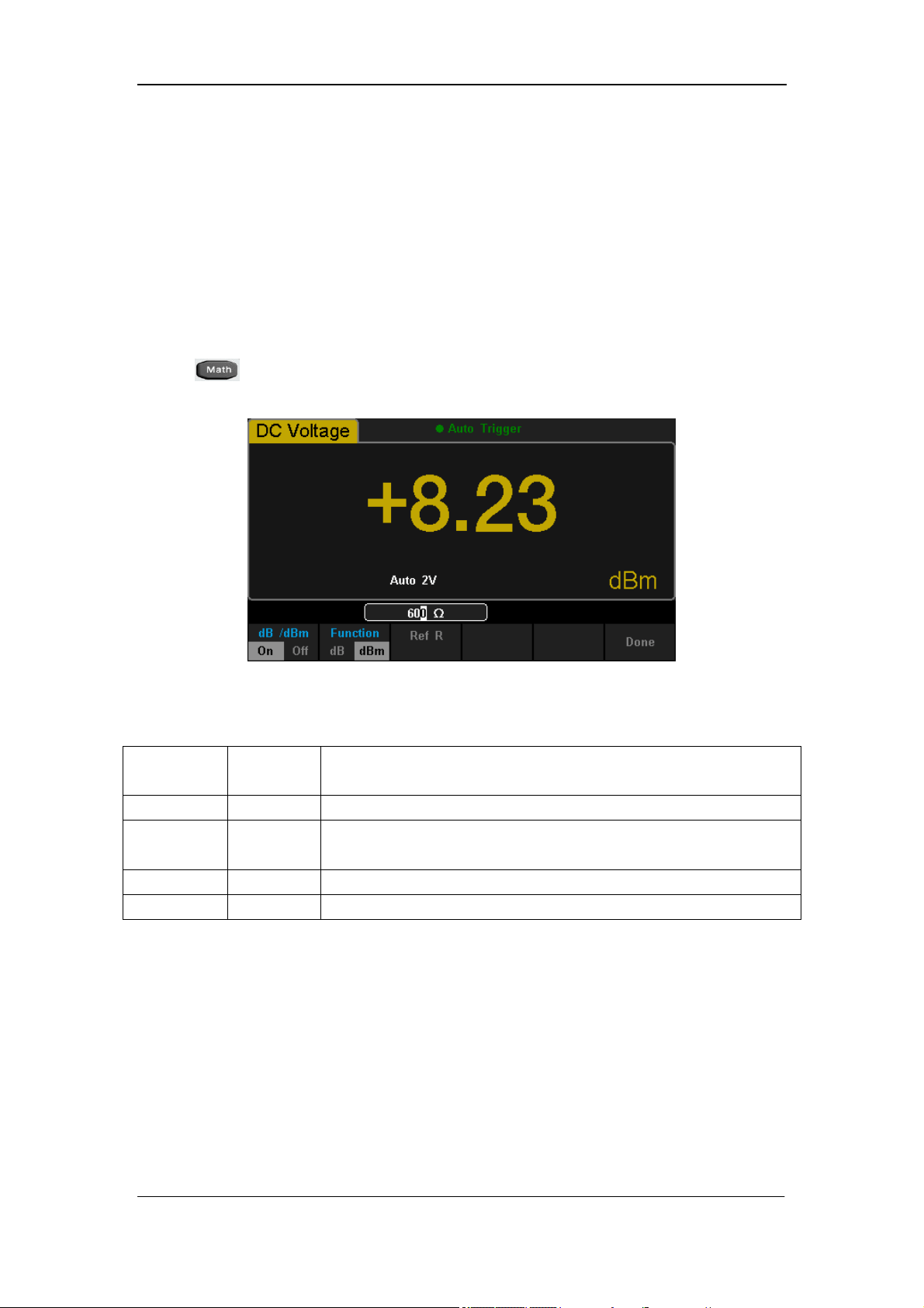
dBm
The dBm function is logarithmic and based on a calculation of power delivered
to a reference resistance, relative to 1 mill watt. Besides,this function only
applies to AC voltage and DC voltage measurements.
Press →【dB/dBm】→【On】and select【Function dBm】to enter the
interface shown in the following diagram.
Diagram 2- 60 dBm Function Interface
Table 2- 24 dB Measurement Function Menu Function Description
Function
Menu
Settings
Description
dB/dBm On/Off Turn on or turn off dB or dBm function.
Function
dBm
Open dBm function and the lower right corner of the
main display show “dBm”.
Ref R Set the parameter via direction keys: 50Ω ~ 8000Ω.
Done Save all changes and return to the higher level menu.
The computation method of the dBm:
When dBm function is turned on, the measured value of voltage is transformed
into dBm according to the following formula.
dBm = 10 x Log
10
[(Reading
2
/ R
REF
) / 0.001W]
SIGLENT
SDM3055 Digital Multimeter 69
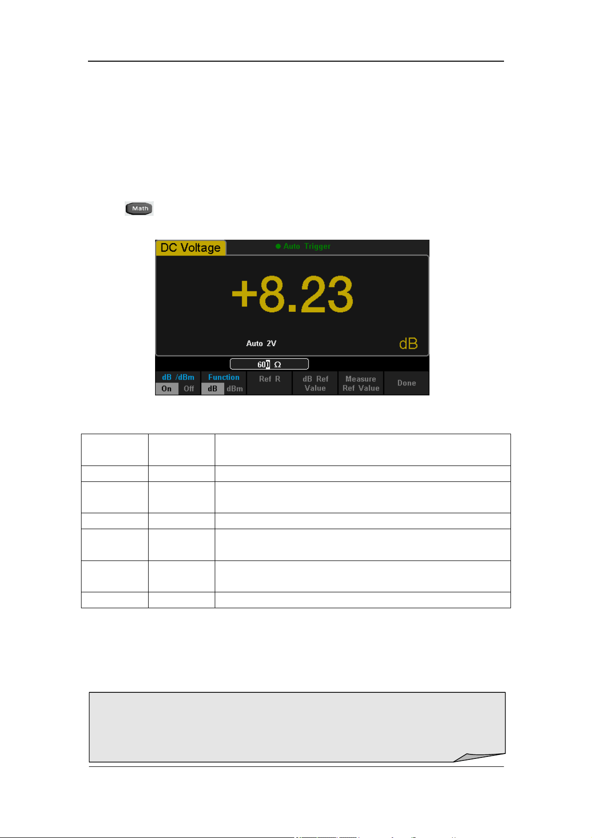
dB
Each dB measurement is different between the input signal and a stored
relative value, with both values converted to dBm. The dB function applies to
AC voltage and DC voltage measurements only.
Press →【dB/dBm On】and select【Function dB】to enter the interface
shown in the following diagram.
Diagram 2- 61 dB Function Interface
Table 2- 25 dB Measurement Function Menu Function Description
Function
Menu
Settings Description
dB/dBm On/Off Turn on or turn off dB or dBm function.
Function
dB
Open dB function and the lower right corner of the
main display show “dB”.
Ref R Set the parameter via direction keys: 50Ω ~ 8000Ω.
dB Ref
Value
Set the referred value of dB.
Measure
Ref Value
Set the referred value of measurement.
Done Save all changes and return to the higher level menu.
The computation method of the dB:
dB = 10 x Log
10
[(Reading
2
/ R
REF
) / 0.001W] – (dB setting value)
R
REF
expressed measuring the resistance value in the actual electric circuit.
Range of the dB setting value: -120 dBm ~ +120 dBm. The default is 0 dBm.
dB value:
Input a value in dB setting interface by direction button, and then store it as
dB setting value.
Settings of dB value are stored in volatile memory.
SIGLENT
70 SDM3055 Digital Multimeter
Relative Value
Relative value is used for relative measurement. Actual measurement reading
is the depression between measurement value and preset value.
The Multimeter allows operating for the following parameters: DC Voltage, AC
Voltage, DC Current, AC Current, Resistance, Frequency, Period,
Capacitance and Temperature.
Press →【Rel Value】to enter the interface shown in the following
diagram.
Diagram 2- 62 Relative Operation
Table 2- 26 Rel Value Operation Function Menu
Function
Menu
Description
Value Select current measurement value as preset value.
Off Turn off the relative operation function.
The computation method of the dB:
When dBm function is turned on, the result of relative measurement will show
on the screen.
Main display = Measurement value – Preset value
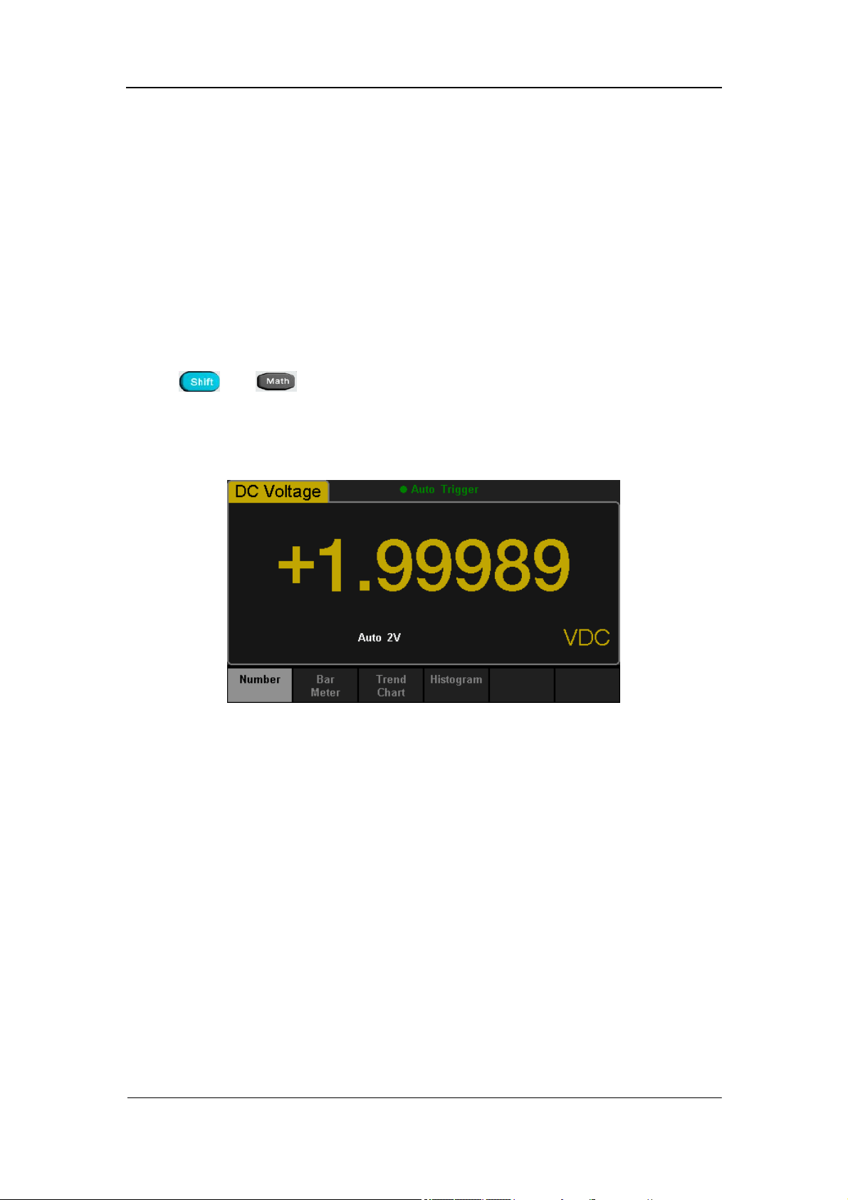
SIGLENT
SDM3055 Digital Multimeter 71
Display Mode
The Multimeter supports four types of way to view measured data: “Number”,
“Bar Meter” ”Trend Chart” and “Histogram”.
Number
Press and to open the menu of display mode and press【Display】
to enter the following interface. “Number” is always the selected mode when
the Multimeter is turned on.
Diagram 2- 63 Number Display Mode
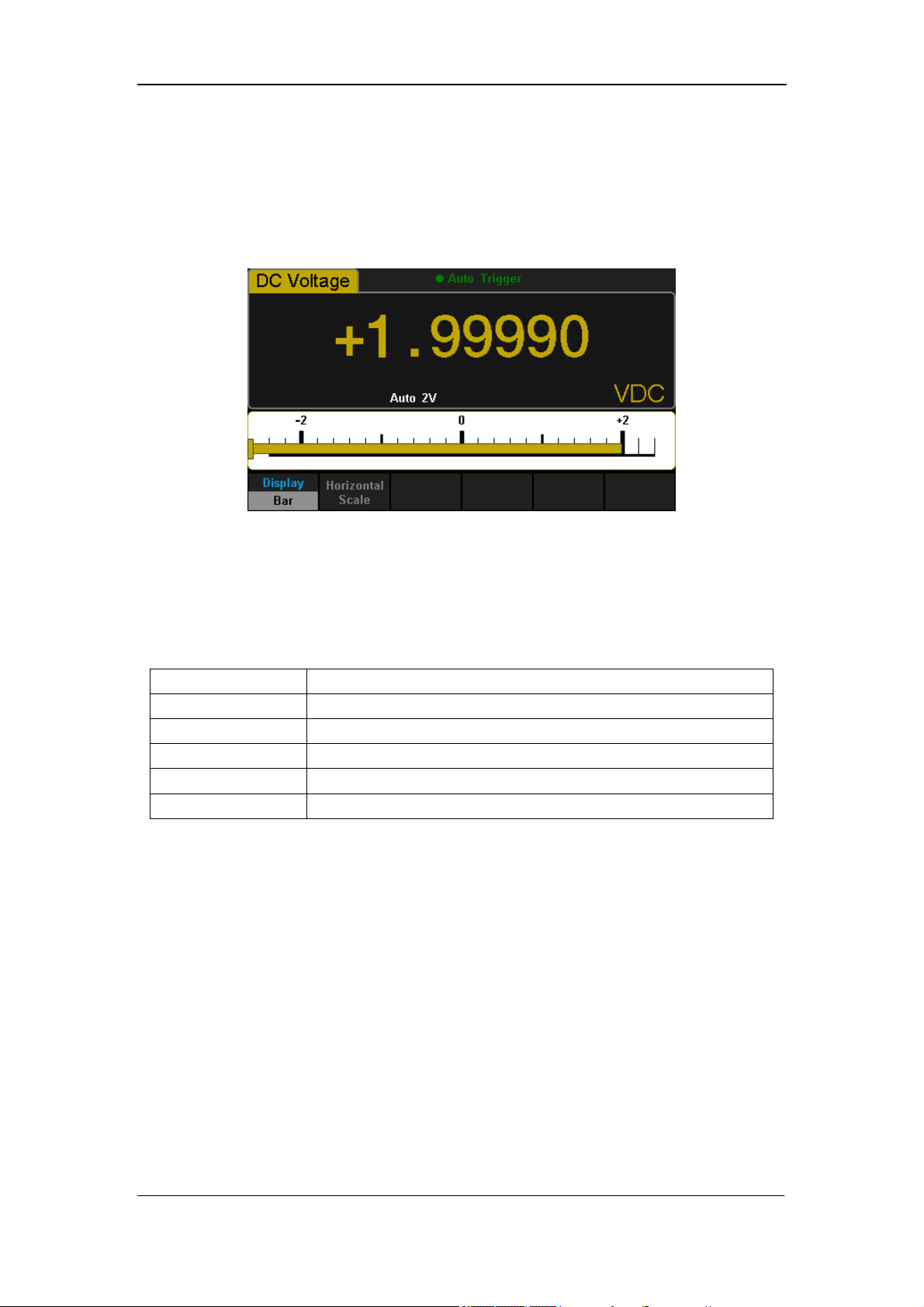
SIGLENT
72 SDM3055 Digital Multimeter
Bar Meter
Operating Steps:
1. Press【Bar Meter】to enter Bar Meter display mode.
Diagram 2- 64 Bar Meter Display Mode
2. Press【Horizontal Scale】to choose the way to set the vertical scale as
Default or Manual mode.
Table 2- 27 To Set the Vertical Scale of Bar Meter manually
Function Menu Description
Low Set the low value of horizontal scale.
High Set the high value of horizontal scale.
Center Set the center value of horizontal scale.
Span Set the span of horizontal scale.
Done Save all changes and return to the higher level menu.
SIGLENT
SDM3055 Digital Multimeter 73
Trend Chart
Operating Steps:
1. Press【Trend Chart】to enter Trend Chart display mode. The default vertical
scale is -2V to 2V when DC Voltage measurement is selected.
Diagram 2- 65 Trend Chart Display Mode
Table 2- 28 Trend Chart Display Mode
Function Menu Description
Display
Trend
Currently selected display mode is Trend Chart.
Recent
All
Show recent or all readings.
Horizontal Scale
Choose the mode of Horizontal Scale.
Autoscale Once Automatically set the horizontal scale once.
Clear Readings Clear all current readings and restart statistics.
2. Press【Horizontal Scale】to choose the way to set the horizontal scale as
Default , Auto or Manual mode.
Press【Auto】and the Multimeter will set the vertical scale automatically.
Diagram 2- 66 Auto Vertical Scale
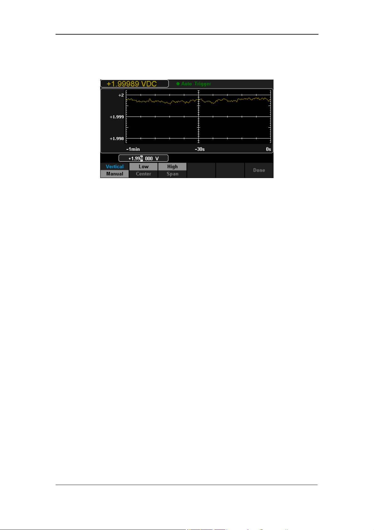
SIGLENT
74 SDM3055 Digital Multimeter
Press【Manual】and you can set the vertical scale manually, as the following
diagram shows.
Diagram 2- 67 Manual Vertical Scale
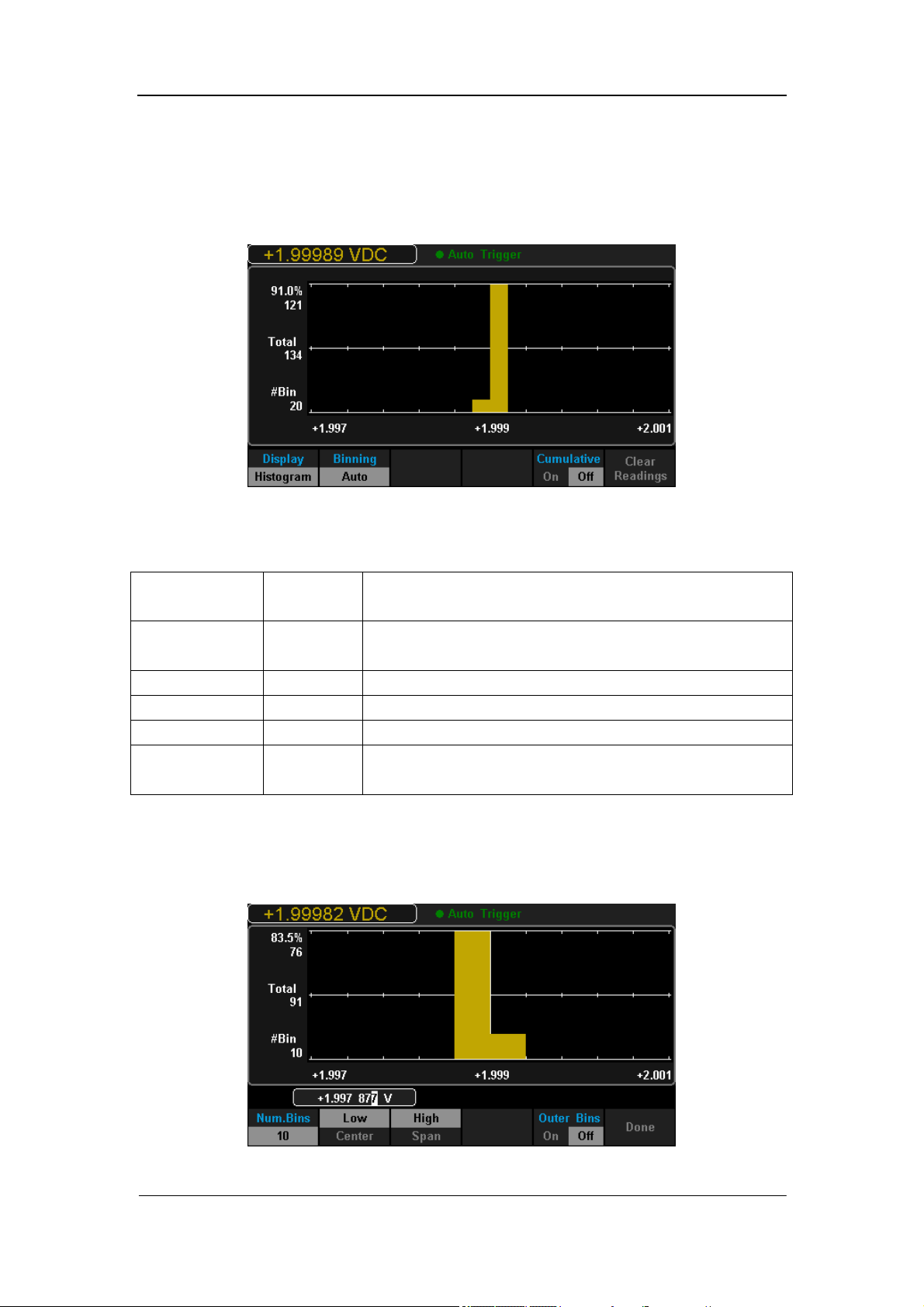
SIGLENT
SDM3055 Digital Multimeter 75
Histogram
Operating Steps:
1. Press【Histogram】to enter Histogram display mode.
Diagram 2- 68 Histogram Display Mode
Table 2- 29 Histogram Display Mode
Function
Menu
Settings Description
Display
Histogram
Currently selected display mode is Histogram.
Binning Set Binning as Auto or Manual mode.
Bin Set Set the parameters of Bin.
Cumulative On/Off Turn on or off Cumulative function.
Clear
Readings
Clear all current readings and restart statistics.
2. Press【Binning】to choose the way to set Binning as Auto or Manual mode.
When in Manual mode, press【Bin Settings】to enter the following interface.
Diagram 2- 69 Bin Set Interface

SIGLENT
76 SDM3055 Digital Multimeter
Table 2- 30 Bin Set
Function
Menu
Settings Description
Num.Bins
Set the number of Bins, 10, 20, 40, 100, 200 or 400
selected.
Low Set the low value of horizontal scale.
High Set the high value of horizontal scale.
Center Set the center value of horizontal scale.
Span Set the span of horizontal scale.
Outer Bins
On/Off Show the bins beyond the scope or not.
Done Save all changes and return to the higher level menu.
SIGLENT
SDM3055 Digital Multimeter 77
Trigger
The Multimeter supports Trigger function. Press or on the front
panel to trigger the Multimeter by Auto or Single mode .Auto trigger is
considered as a default when the power is on.
Auto Trigger
Press on the front panel one time and Auto Trigger will be started to
capture continuous readings automatically. By the time, the black field of the
screen will show “·Auto Trigger”. Press again and the trigger is stopped.
Single Trigger
Press on the front panel, Single Trigger will be started one time and
generate an effective reading. By the time, the black field of the screen will
show “·Single Trigger”.
Explanation
:
In Remote Mode, the black field just above the screen will show “·Immediate
Trigger”. Press to switch back to the local mode and the Multimeter will
choose Auto Trigger automatically.
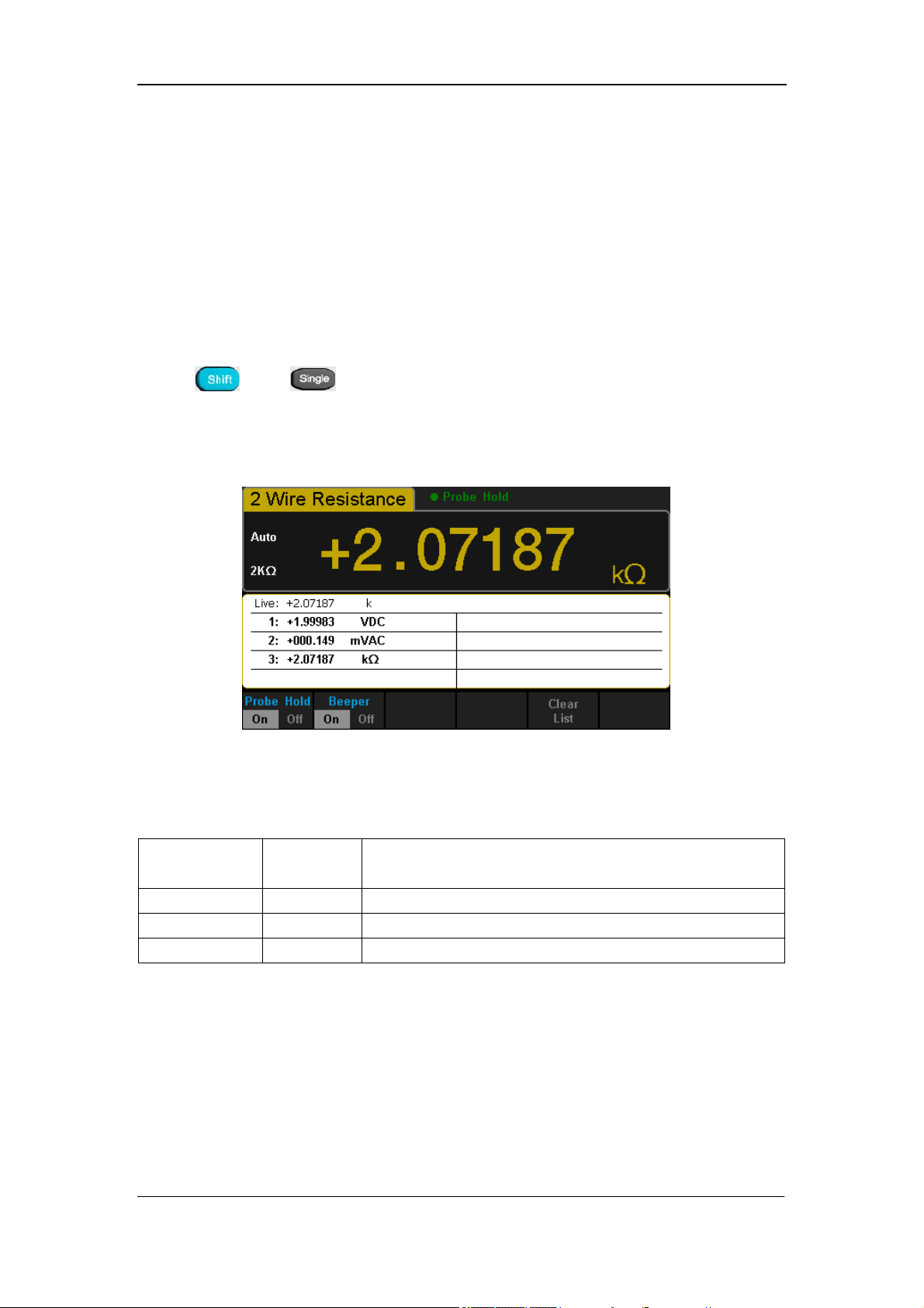
SIGLENT
78 SDM3055 Digital Multimeter
Hold Measurement Function
Hold Measurement function provides users with a stable reading on the
screen of the front panel. When the test leads are put away, the reading is
still held on the screen, which makes users can view measured history data.
Press and to open Hold measurement function interface, the
black field just above the screen will show “·Probe Hold”, as shown in the
following diagram.
Diagram 2- 70 Hold Measurement Function Interface
Table 2- 31 Hold Measurement Function
Function
Menu
Settings Description
Probe Hold On/Off Turn on or off Probe Hold function.
Beeper On/Off Turn on or off the Beeper.
Clear List Clear all current readings and restart to statistics.

SIGLENT
SDM3055 Digital Multimeter 79
Chapter 3 Application Examples
This chapter mainly introduces few application examples to help users
control and manipulate SDM3055 quickly.
Example 1: Reading Statistic Functions
Example 2: To Eliminate Leads Impedance
Example 3: dBm Measurement
Example 4: dB Measurement
Example 5: Limits Test
Example 6: Thermocouple Setting and Measurement
Example 7: To Use Hold Measurement Function
Example 8: To Use Application Software EasySDM
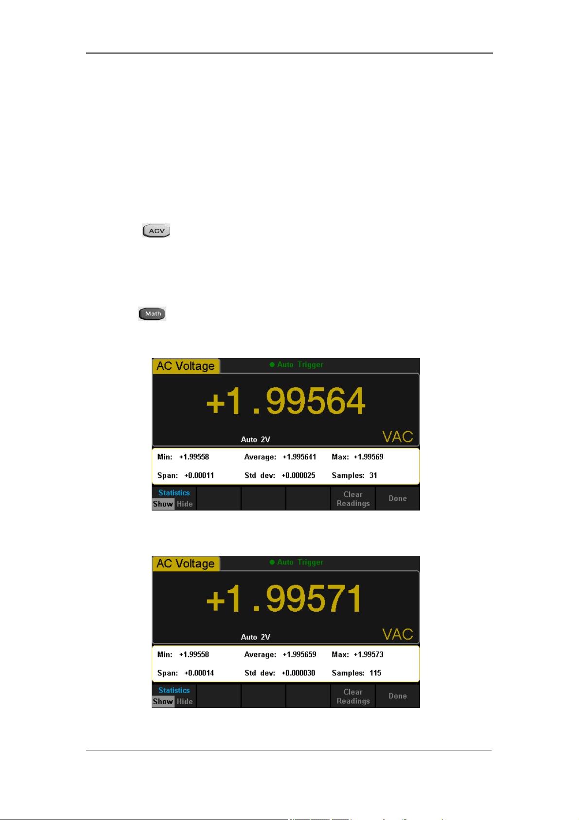
SIGLENT
80 SDM3055 Digital Multimeter
Example 1: Reading Statistic Functions
Introduce how to realize the statistic function during measuring. When
continually measuring few readings, the Multimeter will update statistic values
constantly.
Operating Steps:
1. Press on the front panel to select AC Voltage measurement
function and choose a proper voltage range.
2. Connect the red lead to terminal Input-HI and black lead to terminal
Input-LO as Diagram 2-9.
3. Set the Statistics function parameters.
Press →【Statistics】to turn on the statistics function.
4. Lead test leads into the circuit and start to measure. Statistics will update
with the increasement of samples, as the following diagram shows.
Diagram 3- 1 Statistics 1
Diagram 3- 2 Statistics 2
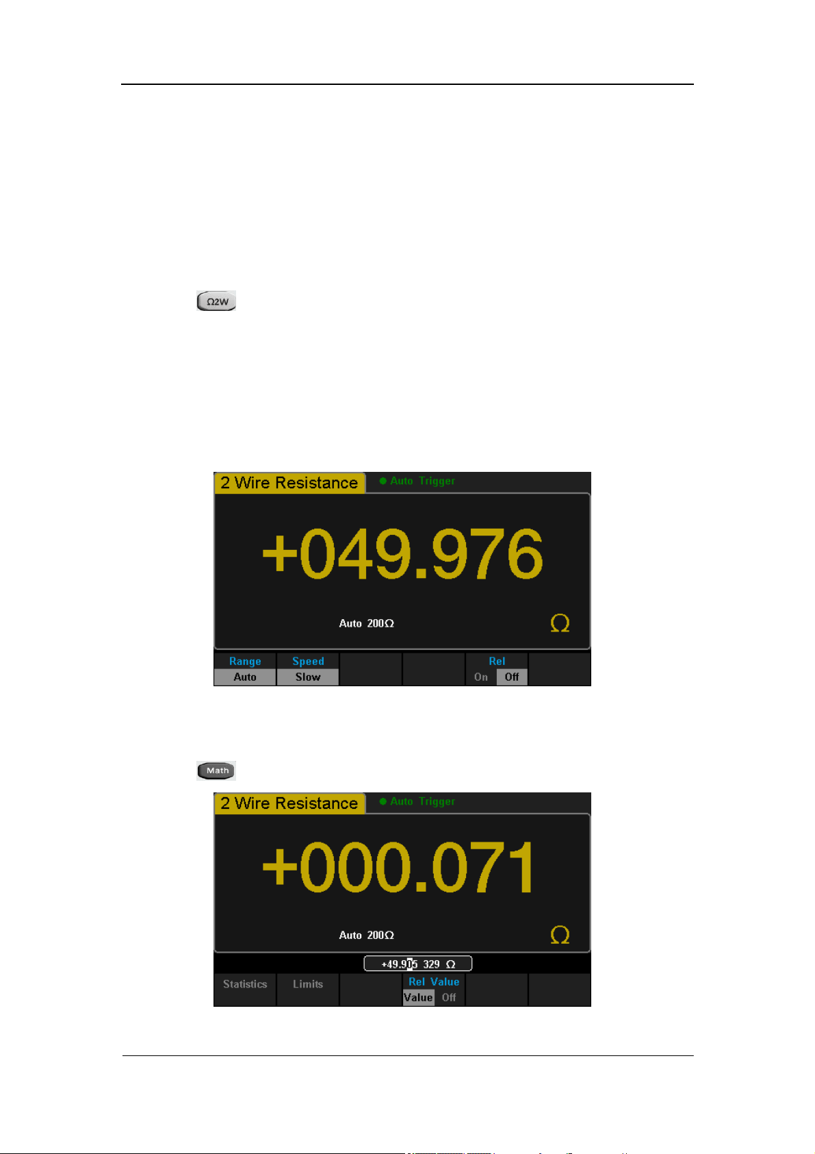
SIGLENT
SDM3055 Digital Multimeter 81
Example 2: To Eliminate Leads Impedance
Relative Operation could eliminate impedance errors from leads when
measuring smaller resistance.
Operating Steps:
1. Press on the front panel to select 2-Wire Resistance measurement
function.
2. Connect the red lead to terminal Input-HI and black lead to terminal
Input-LO as Diagram 2-14.
3. Choose a proper resistance range according to the scope. The default is
Auto Range.
4. Lead impedance will be shown on the screen as follow after connecting
with two leads together.
Diagram 3- 3 Test Lead Impedance
5. Set parameters for Relative operation.
Press →【Rel Value】set relative value as current measured value.
Diagram 3- 4 Set Relative Value
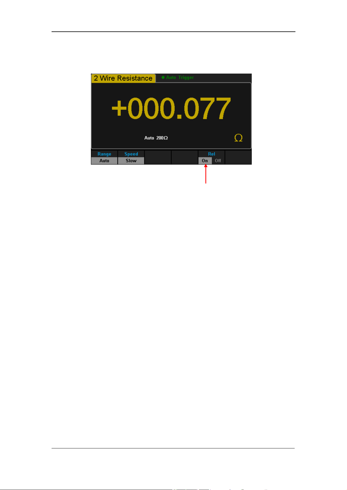
SIGLENT
82 SDM3055 Digital Multimeter
6. Besides, pressing【Rel】on the softkey menu could also open Relative
operation.
The Relative Operation has been turned on.
Diagram 3- 5 Lead Impedance after Operation
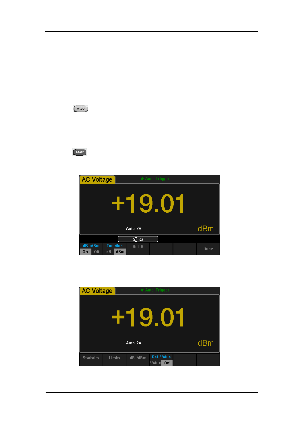
SIGLENT
SDM3055 Digital Multimeter 83
Example 3: dBm Measurement
dBm is commonly used in audio signal measurement. The following will
introduce you how to measure dBm value.
Operating Steps:
1. Press on the front panel to select AC Voltage measurement
function and choose a proper voltage range.
2. Connect the red lead to terminal Input-HI and black lead to terminal
Input-LO as Diagram 2-9.
3. Set the dBm parameters.
Press →【Statistics】to turn on the statistics function and set the
selective value of dBm as a reference value within supposed circuit by
using direction keys: 50Ω.
Diagram 3- 6 Select Reference Resistance as Measurement Value
4. Press【Done】to return to the higher level menu. At this time, the reading
shown on the screen is the Power value of reference resistance.
Diagram 3- 7 dBm Operation Result
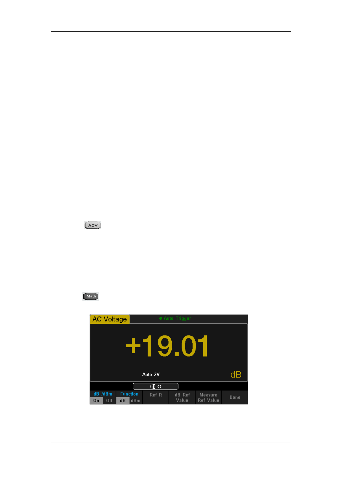
SIGLENT
84 SDM3055 Digital Multimeter
Example 4: dB Measurement
As a common measuring unit, dB has been widely used in electrical
engineering, radio science, mechanics, shock and vibration, mechanical power
and acoustics areas. The following will introduce you how to measure dB
between two circuits.
Operating Steps:
Method 1:
Measure dBm
1
and dBm
2
existing in two circuits separately according to
Example 3, and then dB could be got:.
dB = dBm
1
-dBm
2
Method 2:
1. Press on the front panel to select AC Voltage measurement
function and choose a proper voltage range.
2. Connect the red lead to terminal Input-HI and black lead to terminal
Input-LO as Diagram 2-9.
3. Set up dBm
2
according to Example 3.
4. Press →【dB/dBm】to turn on the dB function and Set parameters
of dB operation (dBm
1
).
Diagram 3- 8 Set the Parameters of dB
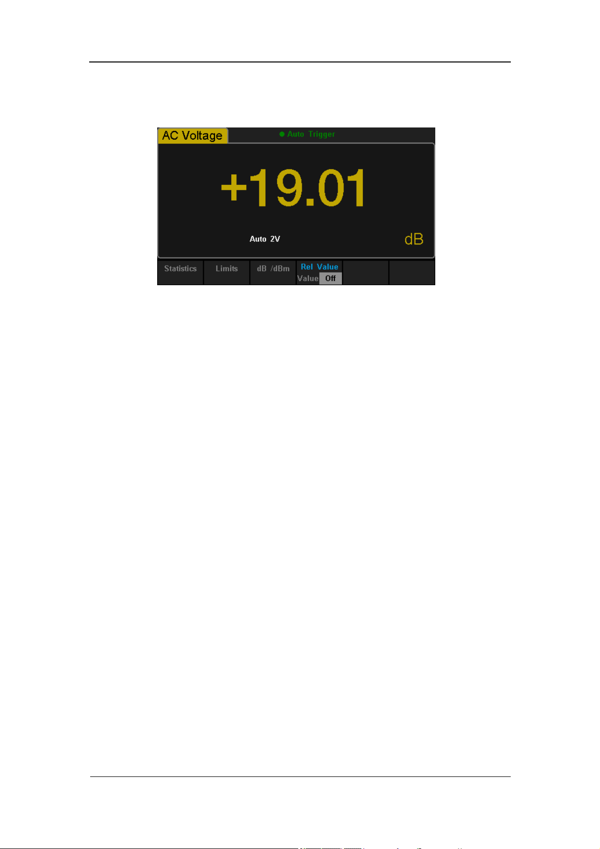
SIGLENT
SDM3055 Digital Multimeter 85
5. Press【Done】to return to the higher level menu. At this time, the reading
shown on the screen is the power difference between two circuits.
Diagram 3- 9 dB Operation Result
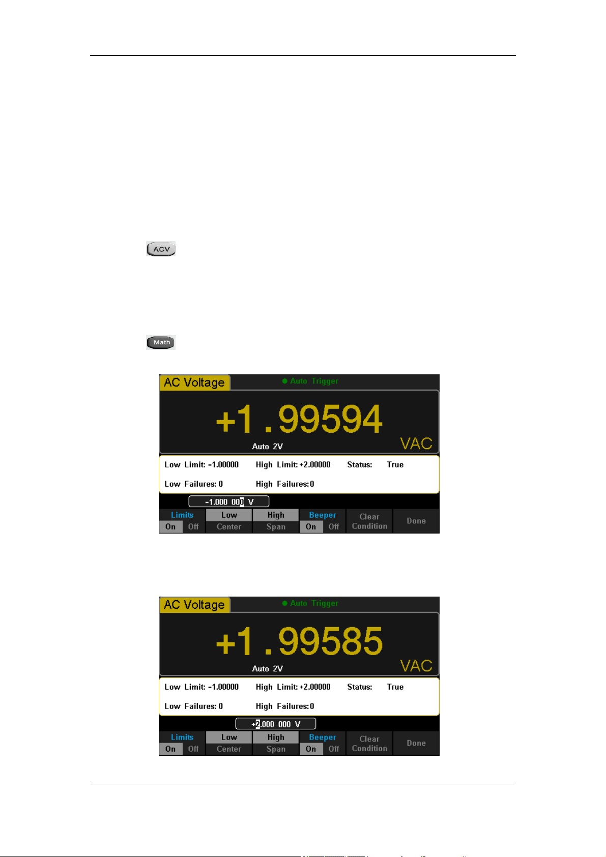
SIGLENT
86 SDM3055 Digital Multimeter
Example 5: Limits Test
Limits Operation hints you the signal is overstep its range according to the
selected High and Low Limit parameters; meanwhile the beeper makes a
sound to alarm (if sound is on.)
Operating Steps:
1. Press on the front panel to select AC Voltage measurement
function and choose a proper voltage range.
2. Connect the red lead to terminal Input-HI and black lead to terminal
Input-LO as Diagram 2-9.
3. Press →【Limits】to set the Limits parameters.
Press【Low】to set the low limit value.
Diagram 3- 10 Set the Low Limit Value
Press【High】to set the high limit value.
Diagram 3- 11 Set the High Limit Value
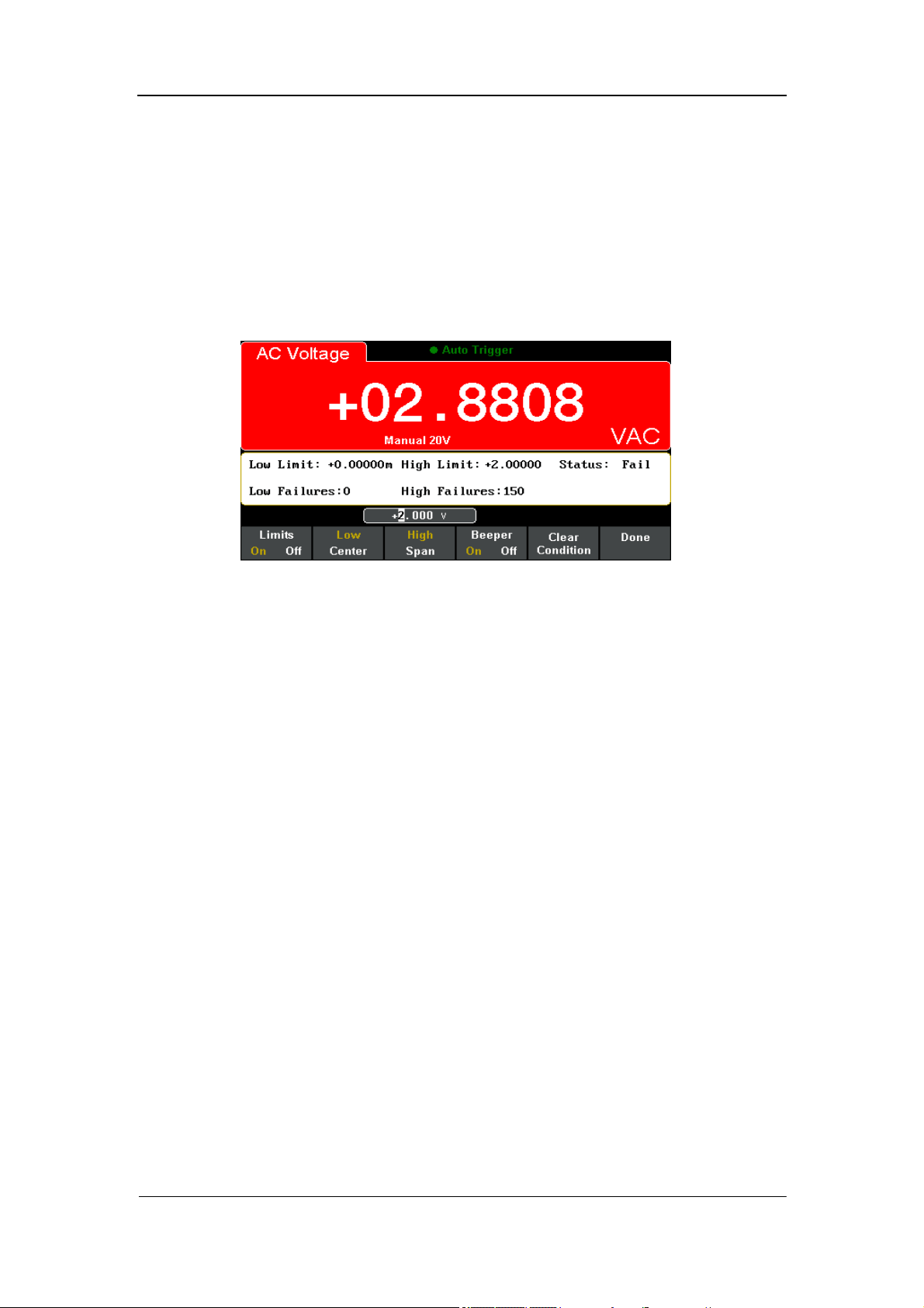
SIGLENT
SDM3055 Digital Multimeter 87
4. Turn on the beeper and start Limits Test. As shown in Diagram 3-11. The
measured result is between the Low and High limits, so the test status is
“True”.
5. If changing the high limit value to 1V, the measured result is not between
the Low and High limits. So the instrument beep once, and the main
display is red. The test status is “Fail” and High Failures is shown. As the
following diagram shows.
Diagram 3- 12 Limits Test Result
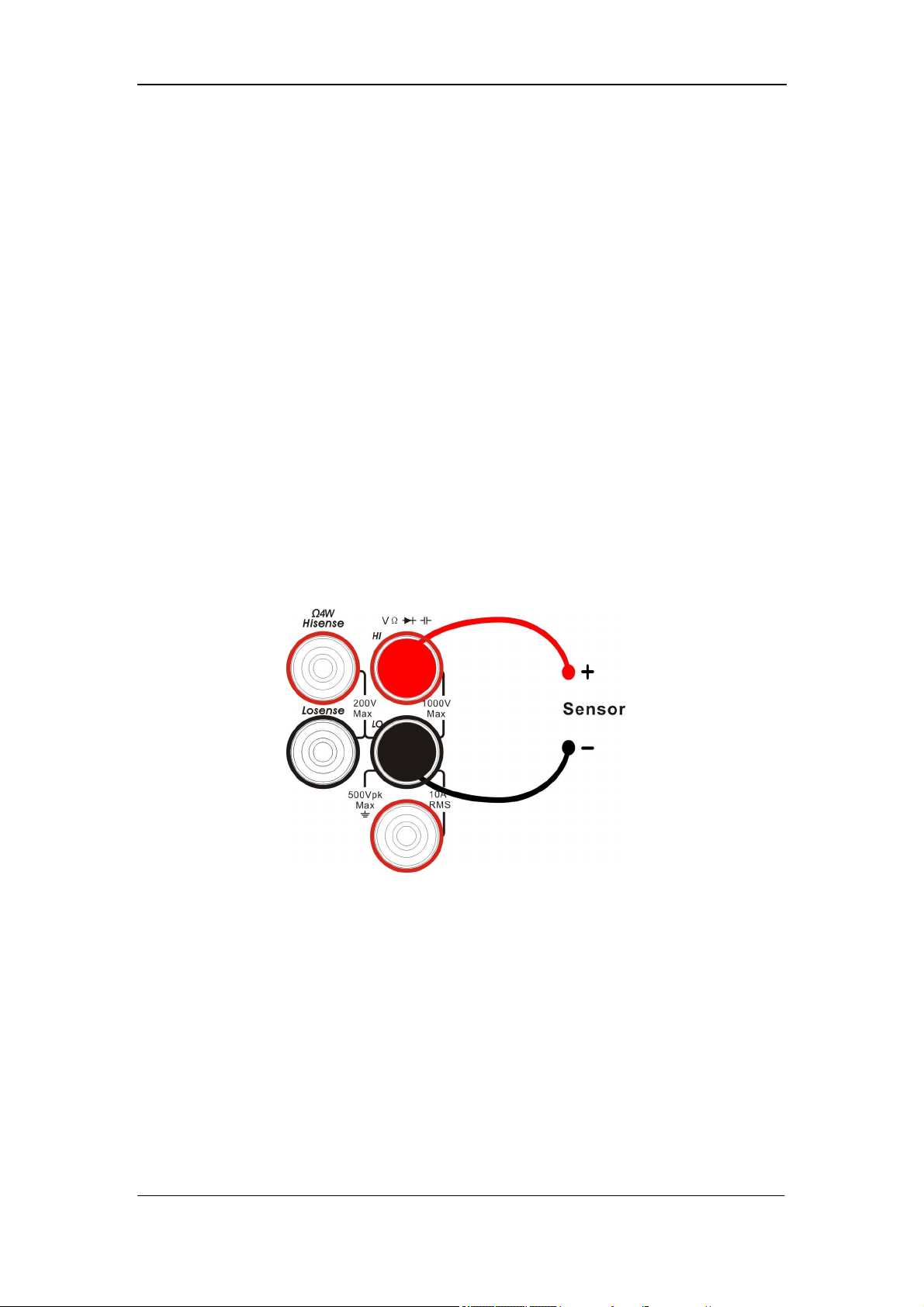
SIGLENT
88 SDM3055 Digital Multimeter
Example 6: Thermocouple setting and
measurement
Thermocouple is a common temperature sensor. Type, voltage and cold-side
temperature are required for thermocouple measurement.
The instrument can measure temperature of HI and LO terminals (cold-side),
and calculate absolute temperature of hot-side. Besides, only the relationship
between thermocouple voltage and cold-side temperature is need to be input
according thermocouple type when you set the thermocouple sensor.
Operating Steps:
1. Please refer to “To Measure Temperature” in chapter 2 to know about the
connection of Sensor.
Diagram 3- 13 Sketch map for connecting the sensor
2. Select the type of thermocouple.
Press【Load】and choose thermocouple measurement. The Multimeter
supports 8 kinds of probe type: B、E、J、K、N、R、S and T.
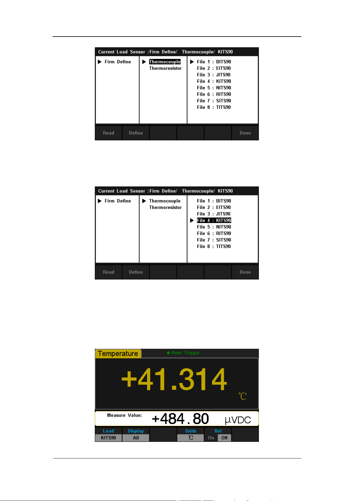
SIGLENT
SDM3055 Digital Multimeter 89
Diagram 3- 14 Select the Type of Thermocouple
3. Use direction keys to select corresponding file and press【Read】to recall
the sensor settings file.
Diagram 3- 15 Select Sensor Settings File
4. Press 【Units】to choose the unit of temperature.
5. View measured result.
Press 【Display】and select display mode of measurement result as “All”
to view measurement value and its corresponding value.
Diagram 3- 16 View measured result
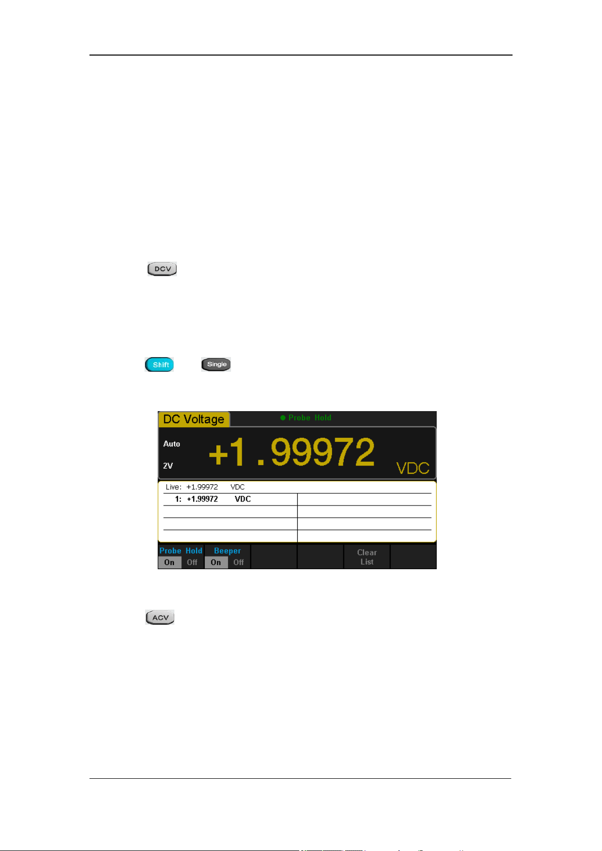
SIGLENT
90 SDM3055 Digital Multimeter
Example 7: To Use Hold Measurement Function
Reading Hold can help user to obtain a stable reading and hold it on the
display of Front Panel. The reading would be held all the same although
testing pen had been moved away. Then we will introduce how to keep the
readings displayed on screen.
Operating Steps:
1. Press on the front panel to select DC Voltage measurement
function and choose a proper voltage range.
2. Connect the red lead to terminal Input-HI and black lead to terminal
Input-LO as Diagram 2-4.
3. Press and to open Hold measurement function interface.
By the time, the screen will record the result of measuring DC voltage, as
shown in the following diagram.
Diagram 3- 17 Result 1
4. Press on the front panel to select AC Voltage measurement
function and choose a proper voltage range.
5. Connect the red lead to terminal Input-HI and black lead to terminal
Input-LO as Diagram 2-9. By the time, the screen will record the result of
measuring AC voltage, as shown in the following diagram.
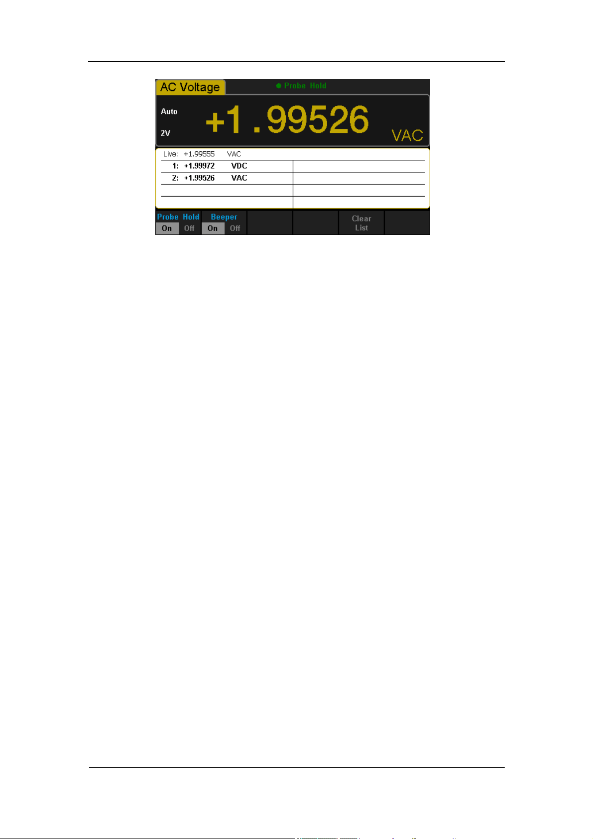
SIGLENT
SDM3055 Digital Multimeter 91
Diagram 3- 18 Result 2
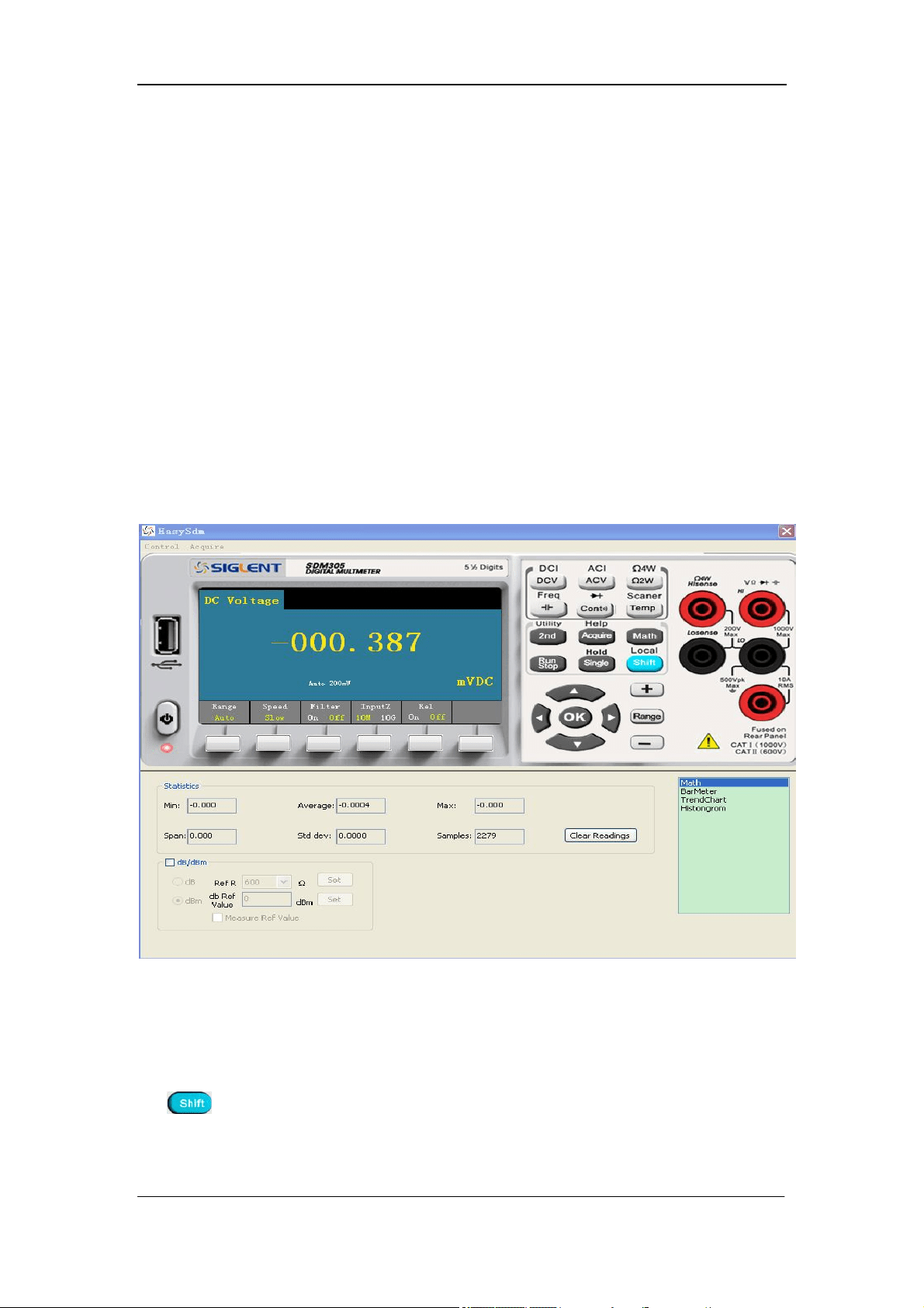
SIGLENT
92 SDM3055 Digital Multimeter
Example 8: To Use Application Software
EasySDM
Remote Control function based on EasySDM enables users to operate
instrument remotely. The software supports basic measurements, Acquire,
Statistics, Trend Chart and Histogram, etc. The method to use the software will
be introduced in details as the following steps.
Operating Steps:
1. Connect the Multimeter to your computer by using USB data wire.
2. Open the main interface of EasySDM, Click【Control】on the upper left
corner and choose【Connect】to contact the instrument with the software.
As shown in the following diagram.
Diagram 3- 19 The Main Interface of EasySDM
3. Click any button on the operating interface to do corresponding operating.
4. If you want to exit the remote control, turn off the software, and then press
on the front panel to close the remote function.
SIGLENT
SDM3055 Digital Multimeter 93
Chapter 4 Measurement Tutorial
True RMS AC Measurement
The AC measurement of the Multimeter has true RMS response. The power
dissipated in a resistor within a time is proportional to the square of the
measured true RMS voltage, independent of wave shape. The instrument can
accurately measure true RMS voltage or current, as long as the wave shape
contains negligible energy above the effective bandwidth.
The AC voltage and AC current functions measure the “AC coupled” true RMS
value, which is to measure the RMS value of the AC component (DC
component is rejected) of the input signal. For sine waves, triangle waves, and
square waves, the AC and AC+DC values are equal since these waveforms do
not contain a DC offset. See the following table 5-1.
Table 5- 1 True RMS AC Measurement of Sine, Triangle and Square waves
Waveform
Crest Factor
(C.F.)
AC RMS
AC+DC
RMS
Sine
Triangle
Square
Non-symmetrical waveforms, such as pulse trains, contain DC voltages which
are rejected by AC coupled true RMS measurements.
An AC coupled true RMS measurement is desirable in situations where you
are measuring small AC signals in the presence of DC offsets. For instance,
measuring AC ripple present on DC power supplies. There are situations,
however, where you might want to know the AC+DC true RMS value. You can
determine this value by combining results from DC and AC measurements as
the following shows. You should perform the DC measurement using 5.5 digit
mode for best AC rejection.
RMS
(AC+DC)
= √ AC
2
+ DC
2
SIGLENT
94 SDM3055 Digital Multimeter
Crest Factor Errors (non-sinusoidal inputs)
A common misconception is that "since an ac Multimeter is true RMS, its sine
wave accuracy specifications apply to all waveforms." Actually, the shape of
the input signal can dramatically affect measurement accuracy. A common
way to describe signal wave shapes is “crest factor”. Crest factor is the ratio of
the peak value to RMS value of a waveform.
Generally speaking, the greater the crest factor, the greater the energy
contained in high frequency harmonics. All Multimeters have errors that are
crest factor dependent. Crest factor errors of SDM3055 are listed in the AC
Characteristics section of chapter 6. (The crest factor errors do not apply for
input signals below 100Hz.)
You can estimate the measurement error due to signal crest factor as shown
below:
Total Error=Error (Sine wave) + Error (Crest factor) + Error (Bandwidth)
Error (Sine wave): error for sine wave as shown in chapter 6.
Error (Crest factor): crest factor additional error as shown in chapter 6. Error
(Bandwidth): estimated bandwidth error as shown below:
Bandwidth error =
×100%(% reading)
C.F.: signal crest factor
F: fundamental frequency of pulse
BW: effective bandwidth of the Multimeter
Example:
Calculate the approximate measurement error for a pulse train input with a
crest factor of 2 and a fundamental frequency of 20 kHz. For this example,
assume 1-year accuracy specifications of the Multimeter: ± (0.05%× reading +
0.03%×range).
Total Error = (0.05%×reading+0.03%×range) + (0.05%×range) +
(0.8%×reading)
=0.85%×reading + 0.08%×range
SIGLENT
SDM3055 Digital Multimeter 95
Loading Errors (AC Voltage)
In the AC Voltage function, the input of SDM3055 appears as a 1MΩ
resistance in parallel with 100pF of capacitance. The test lead that you use to
connect signals to the Multimeter will also add additional capacitance and
loading. The approximate input resistances of the Multimeter at different
frequencies are listed in the following table.
Table 5- 2 Approximate Input Resistances at Different Frequencies
Input Frequency Input Resistance
100Hz 1MΩ
1kHz 850kΩ
10kHz 160kΩ
100kHz 16kΩ
For low frequencies:
Error(%)=
×100%
For high frequencies:
Error(%)=[
-1] ×100%
F: input frequency
R
s
: source resistance
C
m
: input capacitance (100pF) plus test lead capacitance
SIGLENT
96 SDM3055 Digital Multimeter
Application of the Analog Filter
The analog filter of the Multimeter can be used to reduce the influence of the
AC component in DC measurement. Generally the filter may not be required,
but sometimes it can improve the DC measurement. For example, if the
measured DC electrical source has a big AC ripple, the analog filter can
reduce the influence.
The analog filter can’t be used to filter the internal noise of the instrument. It
has no use in DCI opening measurement, DCV short measurement or in
measurement of the output from a precise DC calibration instrument. On the
contrary, it may lead in additional noise and a bigger reading offset. The
Multimeter should be cleared under the selected range and reading rate to
decrease the offset when using the analog filter. If you cannot clear the
instrument, the measured results will have errors. For other ranges and
reading rates, the additional error generated by the filter can be omitted.
Table 5- 3 Analog Filter Error in DCV measurement
Range Reading Rate Additional Analog Filter Error
200mV
Slow 10μV
Middle 20μV
Fast 20μV
2V
Slow 15μV
Middle 20μV
Fast 20μV
20V
Slow 0.8mV
Middle 1mV
Fast 1mV
Table 5- 4 Analog Filter Error in DCI measurement
Range Reading Rate Additional Analog Filter Error
200μA
Slow 0.002% range
Middle 0.005% range
Fast 0.005% range
20mA,2A
Slow 0.040% range
Middle 0.060% range
Fast 0.080% range
200mA
Slow 0.004% range
Middle 0.010% range
Fast 0.010% range
10A
Slow 0.008% range
Middle 0.010% range
Fast 0.010% range

SIGLENT
SDM3055 Digital Multimeter 97
Chapter 5 General Troubleshooting
The following is a list of the troubles that you may meet while using the
Multimeter and their solutions. Please handle as the corresponding steps
when meeting these troubles. If you still can’t handle them, please contact
SIGLENT in time.
1. If the screen of the Multimeter is still dark with nothing displaying
after pressing the power key:
(1) Check if the power has been connected correctly.
(2) Check if the main power switch on the back panel has been turned on
already.
(3) Check if the power fuse has blown. Replace it as desired if it has blown.
(4) Restart the Multimeter after all above steps have been done.
(5) If the instrument still can’t start up properly, please contact SIGLENT.
2. The reading doesn’t change when connecting an AC current signal:
(1) Check if the test lead has been connected to the current jack or LO jack
correctly.
(2) Check if the fuse in the current location on the back panel has blown.
(3) Check if the measuring location has switched to the DCI or ACI place
correctly.
(4) Check if the input is ACI but the measuring location is in DCI place.
3. The reading doesn’t change when connecting a DC current signal:
(1) Check if the test lead has been connected to the current jack or LO jack
correctly.
(2) Check if the fuse in the current location on the back panel has blown.
(3) Check if the measuring location has switched to the DCI or ACI place
correctly.
(4) Check if the input is DCI but the measuring location is in ACI place.
4. USB Disks can’t be recognized by the instrument.
(1) Check if the USB disk can work properly.
(2) Make sure the used USB disk is of Flash type. The instrument doesn’t
support USB disks of hard disk type.
(3) Check if the capacity of the used USB disk is too large. The Multimeter is
recommended not to use USB disks which exceed 4GB.
(4) After restarting the instrument, insert the USB disk again to inspect.
(5) If you still can’t use the USB disk properly, please contact SIGLENT.

SIGLENT
98 SDM3055 Digital Multimeter
Chapter 6 Appendix
Appendix A: Accessories
Standard Accessories:
A Power Cord that fits the standard of destination country.
Two test leads (black and red)
An USB Cable
One backup fuses
A Quick Start
An Application software
NOTE:
We suggest that the length of USB data wire and LAN cable connected to
the instrument should be less than 3m to avoid affecting the product
performance.
All the accessories are available by contacting your local SIGLENT
office.

SIGLENT
SDM3055 Digital Multimeter 99
Appendix B: Warranty summary
SIGLENT warrants that the products that it manufactures and sells will be
free from defects in materials and workmanship for a period of three years
from the date of shipment from an authorized SIGLENT distributor. If a
product proves defective within the respective period, SIGLENT will provide
repair or replacement as described in the complete warranty statement.
To arrange for service or obtain a copy of the complete warranty statement,
please contact your nearest SIGLENT sales and service office. Except as
provided in this summary or the applicable warranty statement, SIGLENT
makes no warranty of any kind, express or implied, including without
limitation the implied warranties of merchantability and fitness for a particular
purpose. In no event shall SIGLENT be liable for indirect, special or
consequential damages.

SIGLENT
100 SDM3055 Digital Multimeter
Appendix C: Daily Maintenance and Cleaning
Maintenance
When storing or placing the instrument, please avoid the liquid crystal display
from direct sunlight for a long time.
NOTE:
To avoid damages to the instrument or probe, please don’t place them in mist,
liquid or solvent.
Cleaning
Please often clean the instrument or probe according to the use of them.
Wipe the external ash of the instrument and probe by a soft rag. Be
careful not to scratch the transparent plastic protective screen when cleaning
the liquid crystal screen.
Use a soft rag that has been soaked by water to clean the instrument
after cutting off the power. Or use 75% isopropyl alcohol of water solvent to
get a more thorough cleaning.
NOTE:
To prevent the surface of the instrument or probe from damages, please
don’t use any corrosive or chemical cleaning reagents.
Please make sure the instrument is already dry before restarting it to
avoid short circuits or personal injuries caused by water.

SIGLENT
SDM3055 Digital Multimeter 101
Appendix D: Contact SIGLENT
SIGLENT TECHNOLOGIES CO., LTD.
Address: 3F, NO.4 building, Antongda Industrial Zone, 3rd Liuxian
Road, 68th District, Baoan District, Shenzhen, P.R.
China
Tel: +86-755-36615186
Fax: +86-755-3591582
Post Code: 518101
E-mail: sales@siglent.com
Http://www.siglent.com

Quick Strat
SDM3055 Digital Multimeter
QS06035-E02A
2014 SIGLENT TECHNOLOGIES CO.,LTD


SIGLENT
SDM3055 Quick start I
Copyright Information
● SIGLENT TECHNOLOGIES CO., LTD. All rights reserved.
● The information provided in this manual replaces all
information printed before.
● SIGLENT Company has the rights to change the
specification and the price.
● Contents in this manual are not allowed to be copied,
extracted and translated without permission by the
company.

SIGLENT
II SDM3055 Quick Start
General Safety Summary
Read the following safety precautions carefully to avoid any
personal injuries or damages to the instrument and any
products connected to it. To avoid potential hazards, please
use the instrument as specified.
Use proper power line.
It’s only allowed to use the special power line which is
approved by local state.
Ground the instrument.
The instrument is grounded through the protective terra
conductor of the power line. The ground conductor must be
connected to the earth to avoid electric shock. Make sure the
instrument is grounded correctly before connecting its input or
output terminals.
Connect the signal wire correctly
The potential of the signal wire is equal to the earth, so do not
connect the signal wire to a high voltage.
Observe all terminal ratings
Please observe all ratings and sign instructions on the
instrument to avoid fire or electric shock. Before connecting
the instrument, please read the manual carefully to gain more
information about the ratings.
Do not operate with suspected failures
If you suspect that the product is damaged, please contact
SIGLENT’s qualified service personnel to inspect it. Any repair
and adjustment to the product or replacing a component
should be done by qualified personnel only.

SIGLENT
SDM3055 Quick Start III
Avoid circuit or wire exposure
Don’t touch exposed contacts or components when the power
is on.
Don’t operate without covers.
Don’t operate the instrument with covers or panels removed.
Use proper fuse.
It’s only allowed to use the specified fuse for the instrument.
Use proper overvoltage protection.
Make sure there is no overvoltage (like voltage caused by
thunder and lightning) reaching to the instrument, otherwise
the operator may suffer an electric shock.
Antistatic protection.
Static electricity will cause damages to the instrument, so test
in antistatic areas as far as possible. Ground its inner and
outer conductors to release the static electricity temporarily
before connecting the cable to the instrument.
Keep good ventilation.
Improper ventilation will cause the rise of the instrument’s
temperature. Keep good ventilation and check the vent and
fan regularly when using it.
Keep the surface of the instrument clean and dry.
Do not operate in wet or damp conditions.
Do not operate in flammable or explosive environment.
The disturbance test of all the models meets the limit
values of A in the standard of EN 61326-1:2013.

SIGLENT
IV SDM3055 Quick Start
Input terminal protection limitation
Protection limitation is defined for the input terminal:
1. Main input(HI and LO)terminal
HI and LO terminals are used for Voltage, Resistance,
Capacitance, Continuity, Frequency, Diode and temperture
measurement. Two protection limitations are defined:
HI-LO protection limitation: 1000VDC or 750AVC. It’s
the maximum measurable voltage. The limitation can be
expressed as 1000Vpk.
LO-ground protection limitation:LO terminal can “float”
500Vpk relative to the ground safely. The maximum
protection limitation of HI terminal relative to the ground is
1000Vpk. Therefore, the sum of the “float” voltage and the
measured voltage can’t exceed 1000Vpk.
2. Sampling (HISense and LOSense) terminal
HISense and LOSense are used for 4-wire Resistance
measurement. Two protection limitations are defined:
HISense-LOSense protection limitation: 2000Vpk.
LOSense-LOSense protection limitation: 2Vpk.
3. Current input (I) terminal
I and LO terminals are used for current measurement. The
maximum current which go through the I terminal is limited to
10A by the fuse on the back panel.
NOTE:
Voltage on the current input terminal corresponds to voltage
on LO terminal. To keep good protection, only use the fuse of
specified type and level to replace this fuse.

SIGLENT
SDM3055 Quick Start V
IEC Measurement Category II Overvoltage Protection
SDM3055 Digital Multimeter provides overvoltage protection
for line-voltage mains connections meeting both of the
following conditions to avoid the danger of electric shock:
1. The HI and LO input terminals are connected to the
mains under Measurement Category II conditions as
following.
2. The maximum line voltage of the mains is 600VAC.
WARNING:
IEC Measurement Category II includes electrical devices
connected to mains at an outlet on a branch circuit, such as
most small appliances, test equipments, and other devices
that plug into a branch outlet or socket.
SDM3055 is capable of making measurements with the HI
and LO inputs connected to mains in such devices (up to
600VAC) or the branch outlet itself. However, the HI and LO
terminals of SDM3055 can’t be connected to mains in
permanently installed electrical devices such as the main
circuit-breaker panels, sub-panel disconnected boxes and
permanently wired motors. Such devices and circuits are
prone to exceed the protection limits of SDM3055.
NOTE:
Voltages above 600VAC only can be measured in circuits that
are isolated from mains. However, there may be transient
overvoltage in circuits that are isolated from mains. SDM3055
is able to withstand occasional transient overvoltage up to
4000Vpk. Please don’t use this instrument to measure circuits
that transient overvoltage may exceed this level.

SIGLENT
VI SDM3055 Quick Start
Safety Terms and Symbols
Terms in this manual. Terms may appear in this manual:
WARNING: Warning statements indicate the conditions and
behaviors that could result in injury or loss of life.
CAUTION: Caution statements indicate the conditions and
behaviors that could result in damage to this product
or other properties.
CAT I (1000V): IEC Measurement Category I. The highest
measurable voltage is 1000Vpk in the HI-LO terminal.
CAT II (600V): IEC Measurement Category II. Inputs may be
connected to mains (up to 600VAC) under Category II overvoltage
conditions.
Terms used on the instrument. Terms may appear on the
instrument:
DANGER indicates an injury or hazard that may immediately
happen.
WARNING indicates an injury or hazard that may not immediately
happen.
CAUTION indicates that a potential damage to the instrument or
other property might occur.
Symbols used on the instrument. Symbols may appear on the
instrument:
Hazardous Protective Warning Test Chassis
Voltage Earth Ground Ground Ground

SIGLENT
SDM3055 Quick Start VII
Daily Maintenance and Cleaning
Maintenance
When storing or placing the instrument, please avoid the
liquid crystal display from direct sunlight for a long time.
NOTE:
To avoid damages to the instrument or test leads, please
don’t place them in mist, liquid or solvent.
Cleaning
Please often clean the instrument and test leads according
to the use of them.
Wipe the external ash of the instrument and test leads by a
soft rag. Be careful not to scratch the transparent plastic
protective screen when cleaning the liquid crystal screen.
Use a soft rag that has been soaked by water to clean the
instrument after cutting off the power. Or use 75%
isopropyl alcohol of water solvent to get a more thorough
cleaning.
NOTE:
To prevent the surface of the instrument or test leads from
damages, please don’t use any corrosive or chemical
cleaning reagents.
Please make sure the instrument is already dry before
restarting it to avoid short circuits or personal injuries
caused by water.

SIGLENT
SDM3055 Quick Start VIII
Content
Copyright Information .................................................................................... I
General Safety Summary ............................................................................. II
Safety Terms and Symbols ......................................................................... VI
Daily Maintenance and Cleaning .............................................................. VII
General Inspection ........................................................................................ 1
1. Inspect the shipping container. ............................................................ 1
2. Inspect the instrument. .......................................................................... 1
3. Check the accessories. .......................................................................... 1
Appearance and Size .................................................................................... 2
To adjust the Handle ..................................................................................... 3
Front Panel ...................................................................................................... 4
Rear Panel ....................................................................................................... 5
Connect Power Cord ..................................................................................... 6
Power Selection ............................................................................................. 7
Change the Power Fuse ............................................................................... 7
Connect Test Leads ....................................................................................... 8
Connect USB and LAN Ports ..................................................................... 14
Use Safety Lock ........................................................................................... 15
Troubleshooting ........................................................................................... 16
Contact SIGLENT ......................................................................................... 18

SIGLENT
SDM3055 Quick Start 1
General Inspection
1. Inspect the shipping container.
Please keep the damaged container or cushioning material
until the contents of the shipment have been checked
completely and the instrument has passed the electrical and
mechanical test.
Damages of the instrument caused by the shipment will be
compensated by the shipper or carrier. SIGLENT will not be
responsible for the free repair or replacement.
2. Inspect the instrument.
If there exit any mechanical damages or lacking of
components, or the instrument fails the electrical and
mechanical test, please contact your SIGLENT sales.
3. Check the accessories.
Check the accessories according to the packing list carefully.
If there exit any accessories damaged or missing, please
contact your SIGLENT sales.
SIGLENT
2 SDM3055 Quick Start
Appearance and Size
Front View
Side View
260 mm
105 mm
282 mm
SIGLENT
SDM3055 Quick Start 3
To adjust the Handle
Please grip the handle by the two sides and pull it outward to
adjust the handle position of SDM3055. Then rotate the handle
to the appropriate position. Please operate as the following
figure:
Handle Adjustment
Horizontal Position Carrying Position
SIGLENT
4 SDM3055 Quick Start
Front Panel
LCD Display USB Host
Power Key Menu Operation Keys
Basic measurement keys Auxiliary Measurement Keys
Enable trigger key Range/Direction Keys
Signal input terminals
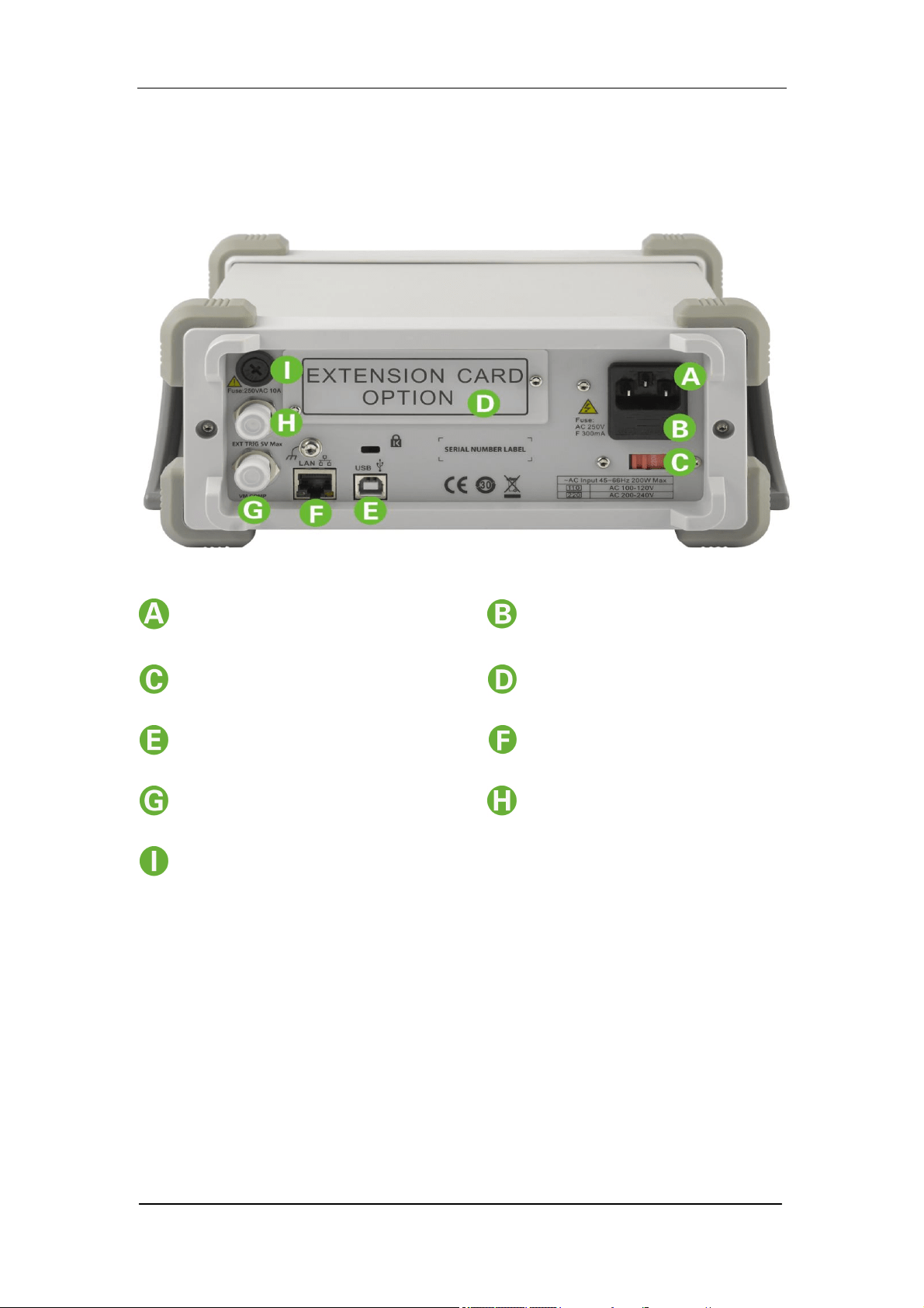
SIGLENT
SDM3055 Quick Start 5
Rear Panel
Power Socket Power Fuse
AC Voltage Selector Inspection card
[1]
USB Device(USBTMC) LAN
VMC Output Ext trigger
Current Input Fuse
Explanation:[1] Only SDM3055S support inspection card.
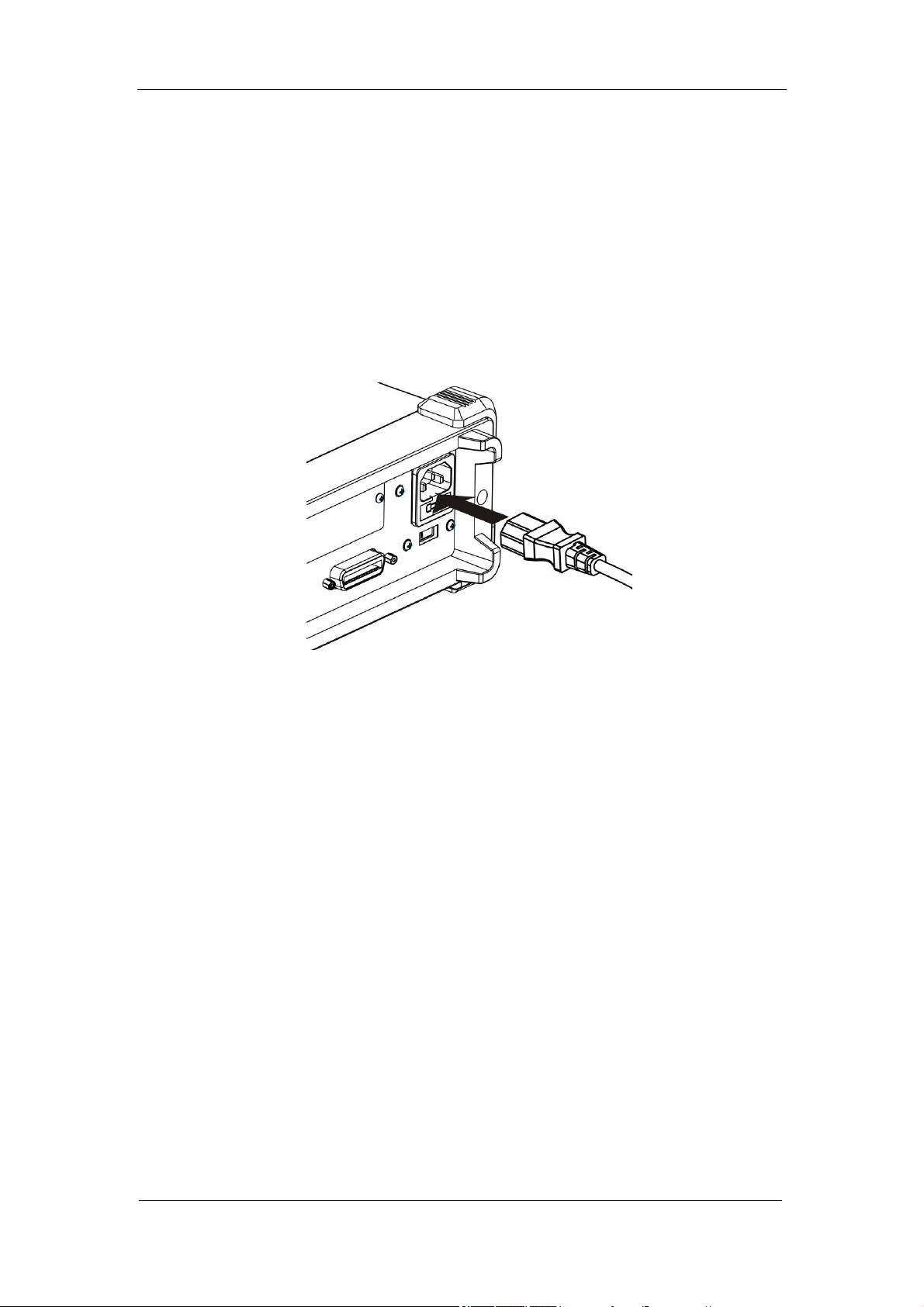
SIGLENT
6 SDM3055 Quick Start
Connect Power Cord
Before connect the instrument to a power source, please
select the AC voltage selector on the rear panel of your
multimeter according to the power supply.Then connect the
power cord as shown in the following figure.
Connect Power Cord
Press the Power key on the front panel to start up the
multimeter.
If unable to start up the multimeter, take the follow steps:
1. Check the power cord connection.
2. After the inspection, if the power key is not lit, please take
out the fuse and check, refer to the fuse specification shown
in the User Manual to change the fuse if needed.
4. After the above inspections, the power key is still not lit,
please contact SIGLENT for help.
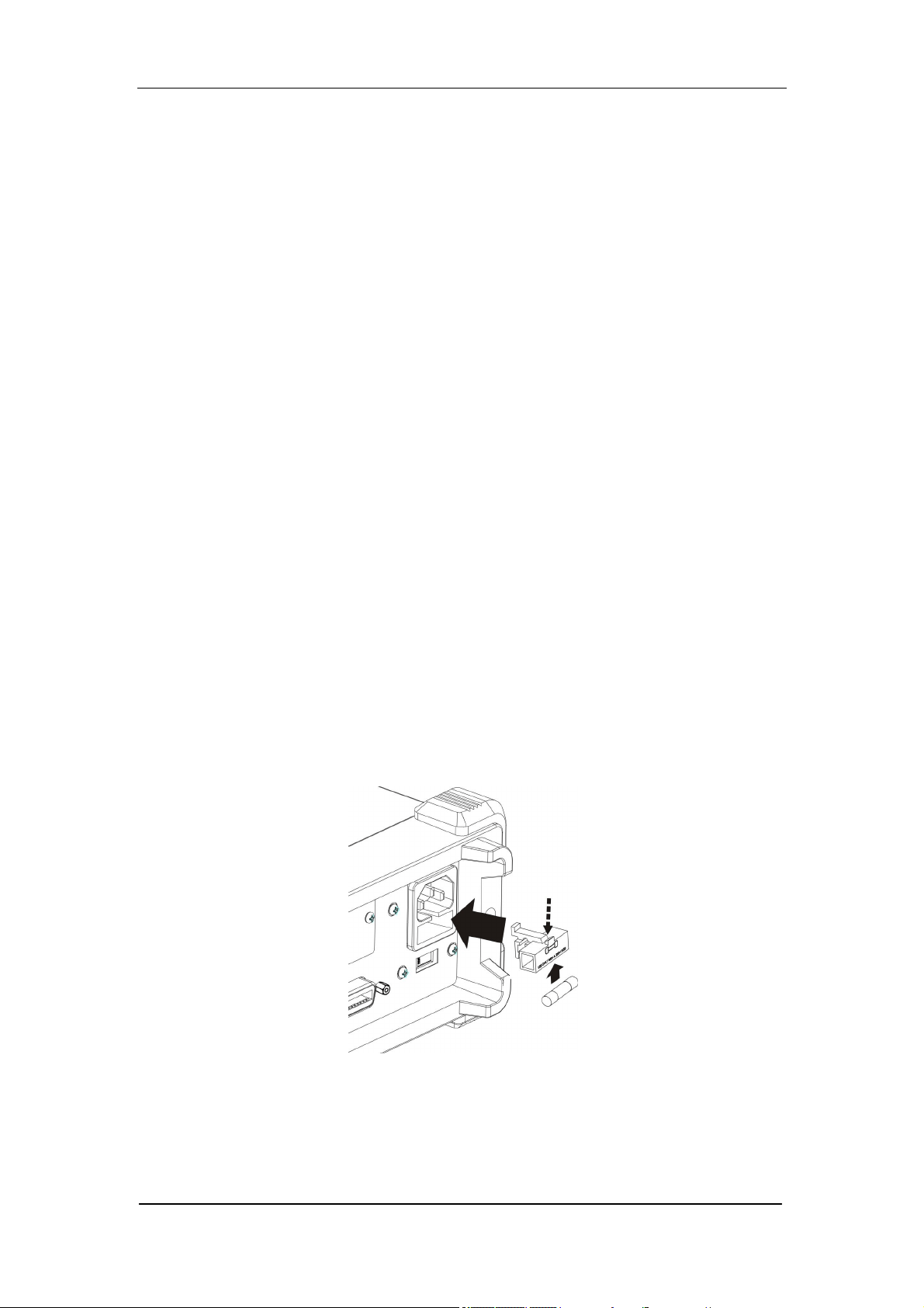
SIGLENT
SDM3055 Quick Start 7
Power Selection
The Multimeter is able to operate on multiple power
distribution standards and must be set up according to the
supply voltage. If the selected supply voltage doesn’t match
the working voltage while using, the setting of the Multimeter’s
supply voltage must be changed. The power selector is
located under the power fuse on the rear panel.
Change the Power Fuse
The power fuse is located in the fuse block on the back panel.
The Multimeter has installed a power fuse before leaving the
factory. It’s a kind of fast-melt, no-burst, F300mA, 5×20mm
one.
Change the fuse
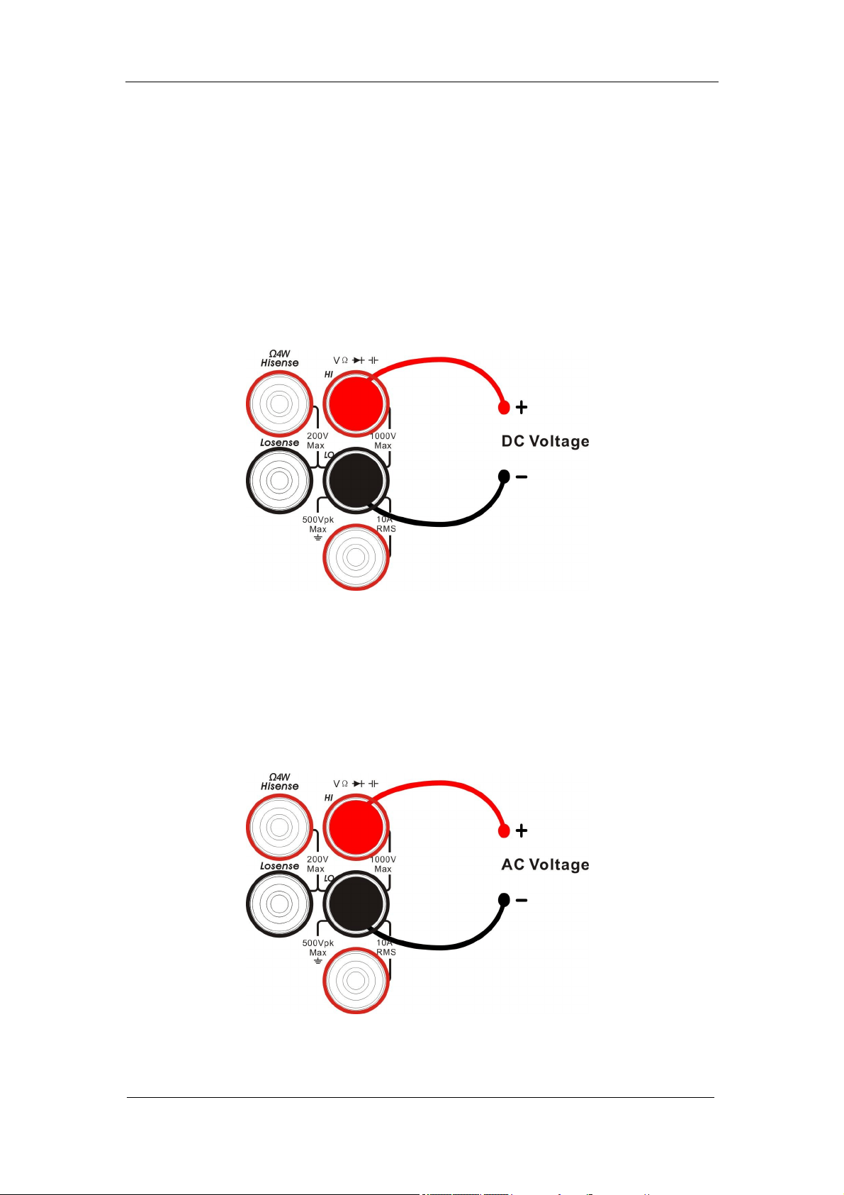
SIGLENT
8 SDM3055 Quick Start
Connect Test Leads
1. DC Voltage Measurement
Connect the test leads and tested circuit as the following
figure, red test lead to the HI Terminal and black lead to the
LO Terminal.
2. AC Voltage Measurement
Connect the test leads and tested circuit as the following
diagram, red test lead to the HI Terminal and black lead to
the LO Terminal.
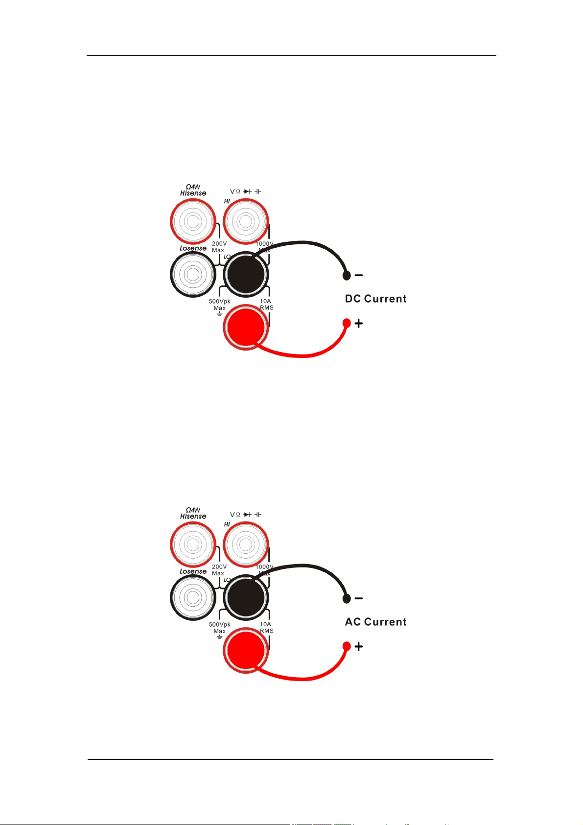
SIGLENT
SDM3055 Quick Start 9
3. DC Current Measurement
Connect the test leads and tested circuit as the following
diagram, red test lead to the HI Terminal and black lead to
the LO Terminal.
4. AC Current Measurement
Connect the test leads and tested circuit as the following
diagram, red test lead to the HI Terminal and black lead to
the LO Terminal.
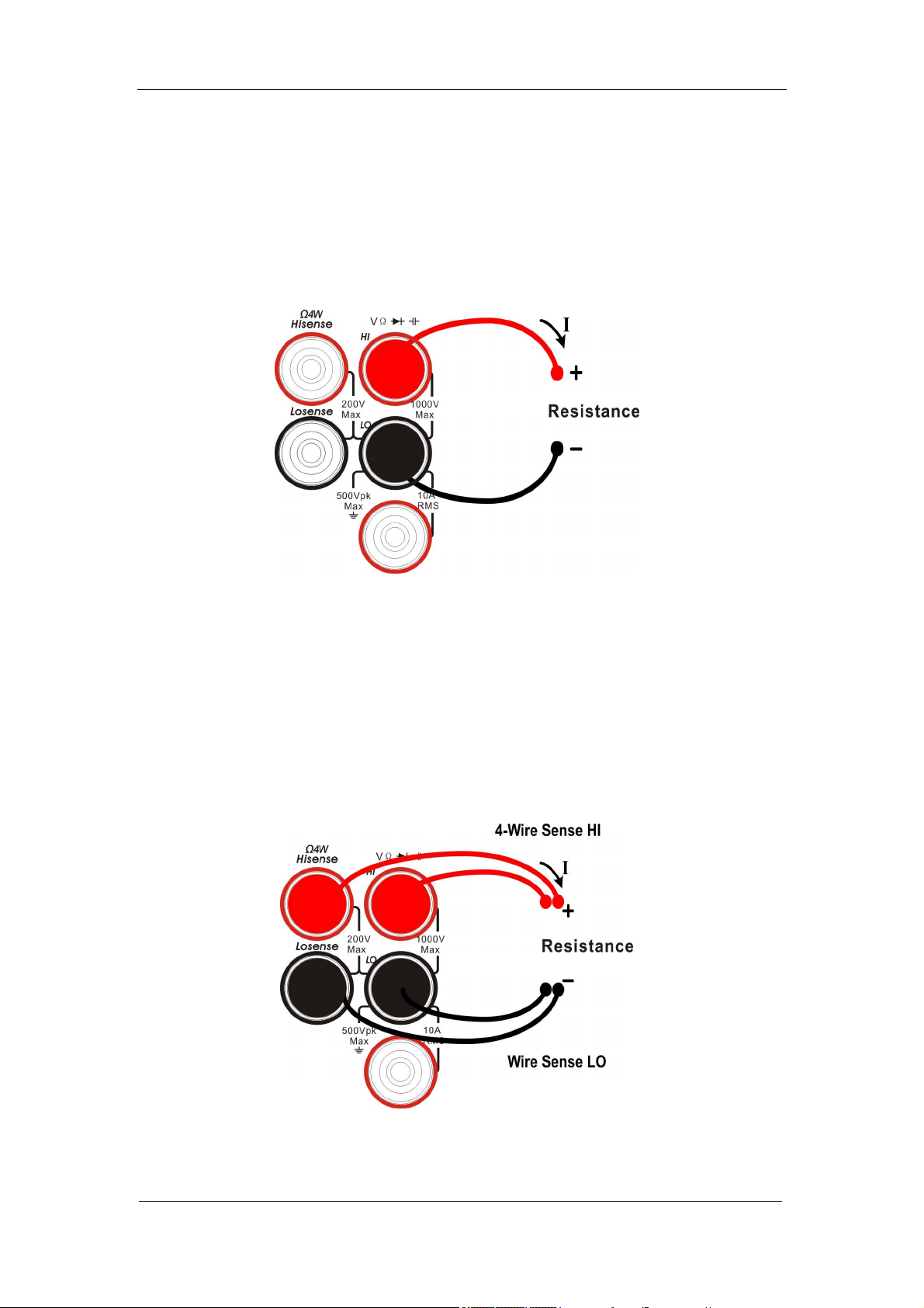
SIGLENT
10 SDM3055 Quick Start
5. 2-Wire Resistance Measurement
Connect the test leads and tested circuit as the following
diagram, red test lead to the HI Terminal and black lead to
the LO Terminal.
6. 4-Wire Resistance Measurement
Connect the test leads and tested circuit as the following
diagram, red test lead to the HI Terminal and black lead to
the LO Terminal.
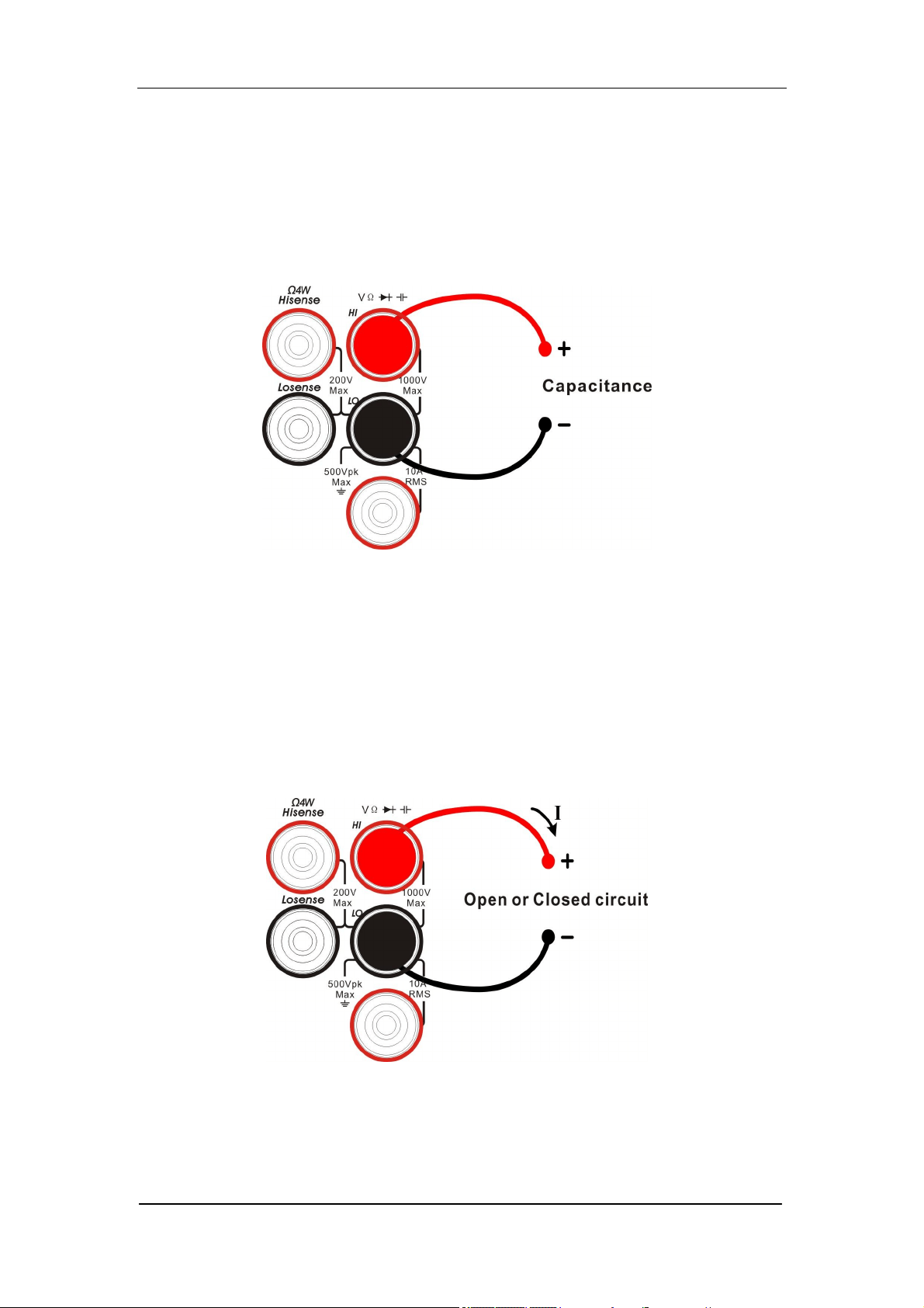
SIGLENT
SDM3055 Quick Start 11
7. Capacitance Measurement
Connect the test leads and tested capacitor as the
following diagram, red test lead to the positive pole of the
capacitor and black lead to the negative pole.
8. Continuity Testing
Connect the test leads and tested circuit as the following
diagram, red test lead to the HI Terminal and black lead to
the LO Terminal.
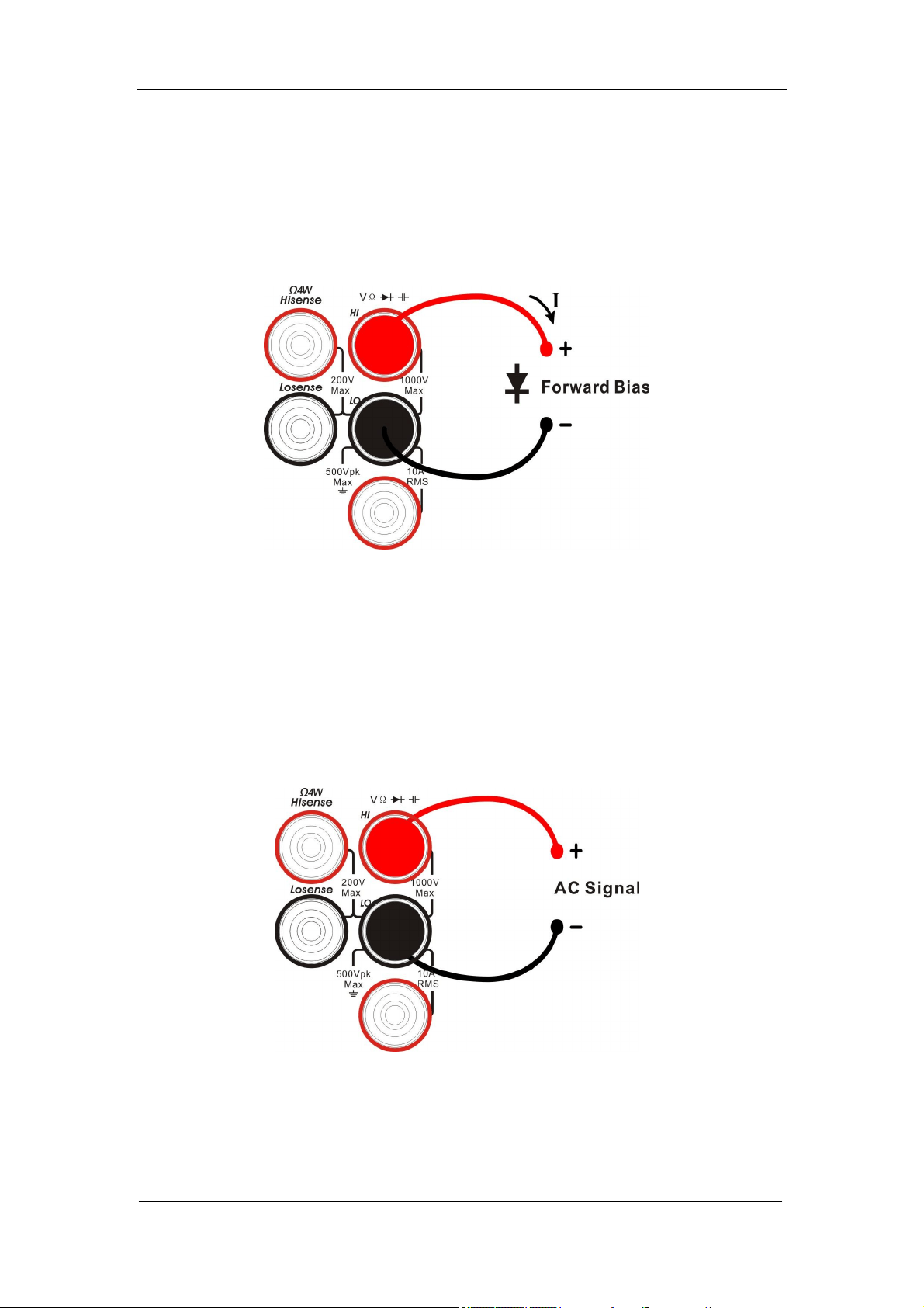
SIGLENT
12 SDM3055 Quick Start
9. Diode Testing
Connect the test leads and tested diode as the following
diagram, red test lead to the HI Terminal and black lead to
the LO Terminal.
10. Frequency/Period Measurement
Connect the test leads as the following diagram, red test
lead to the HI Terminal and black lead to the LO Terminal.
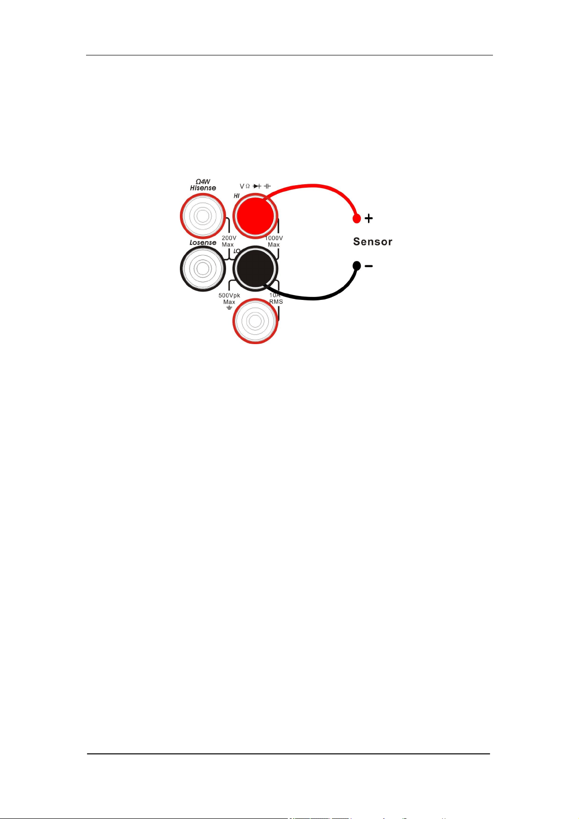
SIGLENT
SDM3055 Quick Start 13
11. Temperture Measurement
Connect the test leads and tested circuit as the following
diagram, red test lead to the HI Terminal and black lead to
the LO Terminal.
TC and RTD Sensor

SIGLENT
14 SDM3055 Quick Start
Connect USB and LAN Ports
SDM3055 has plenty of I/O ports. To use any of the ports,
follow the next instruction:
Connect USB Host Connect USB Device
Connect LAN

SIGLENT
SDM3055 Quick Start 15
Use Safety Lock
You can use the safety lock to lock the multimeter in a fixed
place if necessary. The methods are as the following:
1. Align the key into the keyhole in the vertical direction of the
back panel.
2. Then rotate clockwise to lock the multimeter.
3. Remove the key at last.

SIGLENT
16 SDM3055 Quick Start
Troubleshooting
The general failures and consequential solutions are listed
below. When you find them, please deal with them in the
following corresponding ways. If the problem proves to be
unsolvable by yourself, please contact SIGLENT for help.
1. If the screen is still dark with nothing displayed after
pressing the power key:
(1) Check if the power is correctly connected.
(2) Check if the power fuse has blown. Replace it if
necessary.
(3) If the instrument still can’t start up properly, please
contact SIGLENT.
2. The reading doesn’t change when connecting an AC
current signal:
(1) Check if the test lead is correctly connected to the
current jack or LO jack .
(2) Check if the fuse in the current location on the back
panel has blown.
(3) Check if the measure location has switched to the DCI or
ACI place correctly.
(4) Check if the input is ACI but the measure location is in
DCI place。

SIGLENT
SDM3055 Quick Start 17
3. The reading doesn’t change when connecting a DC
current signal:
(1) Check if the test lead is correctly connected to the
current jack or LO jack.
(2) Check if the fuse in the current location on the back
panel has blown.
(3) Check if the measure location has switched to the DCI or
ACI place correctly.
(4) Check if the input is DCI but the measure location is in
ACI place.
4. USB storage can’t be recognized:
(1) Check if the USB can work normally.
(2) Make sure that the USB storage being used is of flash
type, the instrument does not support USB of hardware
type.
(3) Make sure that the capacity of the USB storage is not too
large. It is suggested that the capacity of the USB
matches to the multimeter is no larger than 4 G.
(4) Restart the instrument and then insert the USB to check
it.
(5) If it is still in abnormal use, please contact SIGLENT.

SIGLENT
18 SDM3055 Quick Start
Contact SIGLENT
SIGLENT TECHNOLOGIES CO.,LTD
Address:3/F, building NO.4, Antongda Industrial Zone, 3rd
Liuxian Road, Bao’an District, Shenzhen, P.R.China
Tel:0086-755-3661 5186
E-mail:sales@siglent.com
Http://www.siglent.com

Remote Manual
SDM3055/SDM3055A
Digital Mulimeter
RC06035-E01A
2014 SIGLENT TECHNOLOGIES CO.,LTD

SIGLENT Remote Manual
1 SDM3055/SDM3055A
Catalogue
SCPI Command ................................................................................................................................ 2
Introduction to the SCPI Language ........................................................................................... 2
Syntax Conventions .................................................................................................................. 2
Command Separators ................................................................................................................ 3
Using the MIN, MAX and DEF Parameters ............................................................................. 3
Querying Parameter Settings..................................................................................................... 3
IEEE-488.2 Common Commands ............................................................................................. 4
SCPI Parameter Types....................................................................................................................... 5
Command in this Manual .................................................................................................................. 6
1.1. ABORt ...................................................................................................................... 6
1.2. FETCh? ..................................................................................................................... 7
1.3. INITiate[:IMMediate] ............................................................................................... 8
1.4. OUTPut:TRIGger:SLOPe ......................................................................................... 9
1.5. R? ............................................................................................................................ 10
1.6. READ? .................................................................................................................... 11
1.7. SAMPle:COUNt ..................................................................................................... 12
1.8. UNIT:TEMPerature {C|F|K} UNIT:TEMPerature?................................................ 13
System Command ........................................................................................................................ 14
2.1 CALCulate Subsystem ...................................................................................................... 14
2.2 CALCulate:LIMit Subsystem ........................................................................................... 15
2.3 CALCulate:TRANsform:HISTogram Subsystem .......................................................... 19
2.4 CALCulate:SCALe Subsystem ......................................................................................... 26
2.5 CALCulate:AVERage Subsystem ..................................................................................... 31
2.6 CONFigure Subsystem ..................................................................................................... 35
2.7 DATA Subsystem .............................................................................................................. 44
2.8 MEASure Subsystem ........................................................................................................ 46
2.9 SENSe Subsystem Introduction ........................................................................................ 54
2.10 SYSTem Subsystem ........................................................................................................ 90
2.11 TRIGger Subsystem ........................................................................................................ 92

Remote Manual SIGLENT
SDM3055/SDM3055A 2
SCPI Command
Introduction to the SCPI Language
SCPI (Standard Commands for Programmable Instruments) is an ASCII-based
programming language for test and measurement instruments. SCPI commands use a
hierarchical structure known as a tree system. Associated commands are grouped under
a common node or root, thus forming subsystems. A portion of the SENSe subsystem
illustrates this, below.
SENSe:
VOLTage:
DC:RANGe {<range>|MIN|MAX|DEF}
DC:RANGe? [MINimum | MAXimum | DEFault]
SENSe is the root keyword of the command, VOLTage is a second-level keyword, and DC
is a third-level keyword. A colon ( : ) separates consecutive keywords.
Syntax Conventions
The command syntax format is illustrated below:
VOLTage:DC:RANGe {<range>|MIN|MAX|DEF}
Most commands (and some parameters) are a mixture of upper- and lower-case letters.
The upper-case letters indicate the command's abbreviated spelling, which yields shorter
program lines. For better program readability, use the long form.
For example, consider the keyword VOLTage, above. You can type VOLT or VOLTage in
any combination of upper- or lower-case letters. Therefore, VolTaGe, volt and Volt are all
acceptable. Other forms, such as VOL and VOLTAG, will generate an error.
Braces ( { } ) enclose the parameter choices. The braces are not sent with the
command string.
A vertical bar ( | ) separates parameter choices. For example,
{<range>|MIN|MAX|DEF} in the above command indicates that you can specify a
numeric range parameter, or "MIN", "MAX" or "DEF". The bar is not sent with the
command string.
Angle brackets ( < > ) indicate that you must specify a value for the enclosed
parameter. For example, the above syntax statement shows the <range> parameter
in angle brackets. Do not send the brackets with the command string. You must
specify a value for the parameter (for example "VOLT:DC:RANG 10") unless you
select one of the other options shown in the syntax (for example "VOLT:DC:RANG
MIN").
Optional parameters are enclosed in square brackets ( [ ] ). The brackets are not sent
with the command string. If you do not specify a value for an optional parameter, the
instrument uses a default value.

SIGLENT Remote Manual
3 SDM3055/SDM3055A
Command Separators
A colon ( : ) separates consecutive different levels of keywords.. You must insert a blank
space to separate a parameter from a command keyword. If a command requires more
than one parameter, separate adjacent parameters using a comma:
CONF:VOLT:DC 20,1
A semicolon ( ; ) separates commands within the same subsystem and can also
minimize typing. For example, the following string:
TRIG:COUNT 2;SOUR EXT
Equivalent to the following two commands:
TRIG:COUNT 2
TRIG:SOUR EXT
Use a colon and a semicolon to link commands from different subsystems. For example,
in the following example, an error is generated if you do not use both the colon and
semicolon:
TRIG:COUN 2;:SAMP:COUN 2
Using the MIN, MAX and DEF Parameters
For many commands, you can substitute "MIN" or "MAX" in place of a parameter. In some
cases you may also substitute "DEF". For example, consider The following example:
VOLTage:DC:RANGe {<range>|MIN|MAX|DEF}
Instead of selecting a specific value for the <range> parameter, you can substitute MIN to
set the range to its minimum value, MAX to set the range to its maximum value or DEF to
set the range to its default value.
Querying Parameter Settings
You can query the current value of most parameters by adding a question mark ( ? ) to the
command. For example,The following example sets the trigger count to 10
measurements:
TRIG:COUN 10
You can then query the count value by sending:
TRIG:COUN?
You can also query the minimum or maximum count allowed as follows:
TRIG:COUN? MIN
TRIG:COUN? MAX

Remote Manual SIGLENT
SDM3055/SDM3055A 4
IEEE-488.2 Common Commands
The IEEE-488.2 standard defines a set of common commands that perform functions
such as reset, self-test and
status operations. Common commands always begin with an asterisk ( * ), are three
characters in length and may
include one or more parameters. The command keyword is separated from the first
parameter by a blank space. Use a
semicolon ( ; ) to separate multiple commands as shown below:
*RST; *CLS; *ESE 32; *OPC?

SIGLENT Remote Manual
5 SDM3055/SDM3055A
SCPI Parameter Types
The SCPI language defines several data formats to be used in program messages and
response messages.
Numeric Parameters
Commands that require numeric parameters will accept all commonly used decimal
representations of numbers including optional signs, decimal points, and scientific
notation. Special values for numeric parameters such as MIN,MAX and DEF are also
accepted. You can also send engineering unit suffixes with numeric parameters (e.g., M, k,
m or u). If a command accepts only certain specific values, the instrument will
automatically round the input numeric parameters to the accepted values. The following
command requires a numeric parameter for the range value:
VOLTage:DC:RANGe {<range>|MIN|MAX|DEF}
Because the SCPI parser is case-insensitive, there is some confusion over the letter "M"
(or "m"). For your convenience, the instrument interprets "mV" (or "MV") as millivolts,
but "MHZ" (or "mhz") as megahertz. Likewise "MΩ" (or "mΩ") is interpreted as megΩ.
You can use the prefix "MA" for mega. For example, "MAV" is interpreted as megavolts.
Discrete Parameters
Discrete parameters are used to program settings that have a limited number of values
(like IMMediate, EXTernal or BUS). They have a short form and a long form just like
command keywords. You can mix upper- and lower-case letters. Query responses will
always return the short form in all upper-case letters. The following example requires
discrete parameters for the temperature units:
UNIT:TEMPerature{C|F|K}
Boolean Parameters
Boolean parameters represent a single binary condition that is either true or false. For a
false condition, the instrument will accept "OFF" or "0". For a true condition, the instrument
will accept "ON" or "1". When you query a Boolean setting, the instrument will always
return "0" or "1". The following example requires a Boolean parameter:
DISPlay:STATe {ON|1|OFF|0}
Remote Manual SIGLENT
SDM3055/SDM3055A 6
Command in this Manual
1.1. ABORt
Aborts a measurement in progress, returning the instrument to the trigger idle state.
Pameter Typical Return
(none) (none)
Abort a measurement in progress:
TRIG:SOUR IMM //Set the trigger source for immediate trigger
TRIG:COUN 10 //Set the trigger source for 10 times
INIT //Set the trigger state for “wait for trigger”
ABOR //Interrupt the measurement
This command may be used to abort a measurement when the instrument is waiting for a
trigger, or for aborting a long measurement or series of measurements.

SIGLENT Remote Manual
7 SDM3055/SDM3055A
1.2. FETCh?
Waits for measurements to complete and copies all available measurements to the
instrument's output buffer. The readings remain in reading memory.
Parameter Typical Return
(none)
-5.75122019E-04, -5.77518360E-04,
-5.73923848E-04, -5.76020647E-04
Set the trigger source for immediate trigger,the INIT command will instrument in
"waiting for trigger" state, in the immediate trigger condition, measurements will
immediately be triggered and the measurement results are sent to the
measurement of memory,The FETCh? query transfers the measurement from
reading memory to the
instrument's output buffer.
TRIG:SOUR IMM //Set the trigger source for immediate trigger
TRIG:COUN 10 //Set the trigger source for 10 times
INIT //Set the trigger state for “wait for trigger”
FETC? //Read the resulting measurement value
The FETch? query does not erase measurements from the reading memory. You can
send the query multiple times to retrieve the same data.
You can store up to 1,000 measurements in the reading memory of theSDM3055x . If
reading memory overflows, new measurements will overwrite the oldest
measurements stored; the most recent measurements are always preserved. No
error is generated, but the Reading Mem Ovfl bit (bit 14) is set in the Questionable
Data Register's condition register (see Status System Introduction).
The instrument clears all measurements from reading memory when the
measurement configuration changes, or when any of these commands is executed:
INITiate
MEASure:<function>?
READ?
*RST
SYSTem:PRESet

Remote Manual SIGLENT
SDM3055/SDM3055A 8
1.3. INITiate[:IMMediate]
Set the trigger state for “wait for trigger”.Measurements will begin when the specified
trigger conditions are satisfied following the receipt of the INITiate command. This
command also clears the previous set of measurements from reading memory.
Parameter Typical Return
(none) (none)
Set the trigger source for “wait for trigger”,it can effectively receives the
triggersignal:
TRIG:SOUR BUS //Set the trigger source to trigger bus
TRIG:COUN 10 //Set the trigger source for 10 times
INIT //Set the trigger state for “wait for trigger”
*TRG //Send a trigger signal
FETCh? //After measuring can read the measured memory
Storing measurements in reading memory with INITiate is faster than sending
measurements to the instrument's output buffer using READ? (provided you do not
send FETCh? until done). The INITiate command is also an "overlapped" command.
This means that after executing INITiate, you can send other commands that do not
affect the measurements.
You can store up to 1,000 measurements in the reading memory of the SDM3055x. If
reading memory overflows, new measurements will overwrite the oldest
measurements stored; the most recent measurements are always preserved. No
error is generated, but the Reading Mem Ovfl bit (bit 14) is set in the Questionable
Data Register's condition register (see Status System Introduction).
To retrieve the measurements from the reading memory, use FETCh?. Use
DATA:REMove? or R? to read and erase all or part of the available measurements.
The ABORt command may be used to return to idle.

SIGLENT Remote Manual
9 SDM3055/SDM3055A
1.4. OUTPut:TRIGger:SLOPe {POSitive|NEGative}
OUTPut:TRIGger:SLOPe?
Selects the slope of the voltmeter complete output signal on the rear-panel VM Comp
BNC connector.
Parameter Typical Return
{POSitive|NEGative}, default NEGative (none)
Configure DC voltage measurements and make two measurements. The signal
on the rear-panel VM Comp connector will output a positive pulse as each
measurement is completed:
CONF:VOLT:DC 10
SAMP:COUN 2
OUTP:TRIG:SLOP POS
INIT
This parameter is set to its default value after a Factory Reset (*RST) or Instrument Preset
(SYSTem:PRESet).

Remote Manual SIGLENT
SDM3055/SDM3055A 10
1.5. R? [<max_readings>]
Reads and erases all measurements from the reading memory up to the specified
<max_readings>. The measurements are read and erased from the reading memory
starting with the oldest measurement first.
Parameter Typical Return
1 to 10,000
readings
Default is all
readings in
memory
#247-1.06469770E-03,-1.08160033E-03,-1.22469433E-03
The "#2" means that the next 2 digits indicate how many characters will
be in the returned memory string. These two digits are the "47" after the
"#2". Therefore, the remainder of the string is 47 digits long:
-1.06469770E-03,-1.08160033E-03,-1.22469433E-03
Read and remove the three oldest readings:
TRIG:COUN 3
INIT
R? 3
The R? and DATA:REMove? queries allow you to periodically remove measurements
from the reading memory that would normally cause the reading memory to overflow.
You can store up to 1,000 measurements in the reading memory of the SDM3055x. If
reading memory overflows, new measurements will overwrite the oldest
measurements stored; the most recent measurements are always preserved. No
error is generated, but the Reading Mem Ovfl bit (bit 14) is set in the Questionable
Data Register's condition register (see Status System Introduction).
The instrument clears all measurements from reading memory when the
measurement configuration changes, or when any of these commands is executed:
INITiate
MEASure:<function>?
READ?
*RST
SYSTem:PRESet

SIGLENT Remote Manual
11 SDM3055/SDM3055A
1.6. READ?
Read and erase measurement results from reading storage ,up to the specified <
max_readings >.This command reads the data will begin with the first measurement
results.
Parameter Typical Return
(none)
-1.23006735E-03,-1.30991641E-03,-1.32756530E-03,
-1.32002814E-03
Transmission measurements from the reading memory:
TRIG:COUN 4
SAMP:COUN 1
READ?
The FETch? query does not erase measurements from the reading memory. You can
send the query multiple times to retrieve the same data.
You can store up to 1,000 measurements in the reading memory of the SDM3055x. If
reading memory overflows, new measurements will overwrite the oldest
measurements stored; the most recent measurements are always preserved. No
error is generated, but the Reading Mem Ovfl bit (bit 14) is set in the Questionable
Data Register's condition register .
It is important to note that the following command will measurements to empty,
leading to FETCh? The return value of the change:
INITiate
MEASure:<function>?
READ?
*RST
SYSTem:PRESet

Remote Manual SIGLENT
SDM3055/SDM3055A 12
1.7. SAMPle:COUNt {<count>|MIN|MAX|DEF}
SAMPle:COUNt? [{MIN|MAX|DEF}]
Specifies the number of measurements (samples) the instrument will take per trigger.
Parameter Typical Return
1( default) 至 100,000 1
Set a single trigger sampling frequency for 10 times, the back
panel of the VM Comp BNC connector on the oscilloscope will only
observe a pulse:
SAMP:COUN 10 //Set the sampling frequency for 10
times
TRIG:COUN 1 //Set the trigger for 1 times
TRIG:SOUR EXT;SLOP NEG //Set the trigger source to the
external trigger and trigger signal
is set to the falling edge
OUTP:TRIG:SLOP POS //Set the trigger output signal to rise
READ? //Start the wheel measurement and
reading
You can use the specified sample count in conjunction with a trigger count
(TRIGger:COUNt), which sets the number of triggers to be accepted before returning
to the "idle" trigger state. The total number of measurements returned will be the
product of the sample count and trigger count.
You can store up to 1,000 measurements in the reading memory of the SDM3055x. If
reading memory overflows, new measurements will overwrite the oldest
measurements stored; the most recent measurements are always preserved. No
error is generated, but the Reading Mem Ovfl bit (bit 14) is set in the Questionable
Data Register's condition register .
This parameter is set to its default value after a Factory Reset (*RST) or Instrument
Preset (SYSTem:PRESet).

SIGLENT Remote Manual
13 SDM3055/SDM3055A
1.8. UNIT:TEMPerature {C|F|K}
UNIT:TEMPerature?
Selects the units (°C, °F or Kelvin) to be used for all temperature measurements.
Parameter Typical Return
{C|F|K},default C C, F or K
Set to return the result in °F
UNIT:TEMP F //Set the temperature measurement unit in °F
MEAS:TEMP? //Recovery temperature default configuration
and read a set of temperaturemeasurements
The command also accepts CEL or FAR, but the query returns C or F.
This parameter is set to its default value after a Factory Reset (*RST) or Instrument
Preset (SYSTem:PRESet).
Remote Manual SIGLENT
SDM3055/SDM3055A 14
System Command
2.1 CALCulate Subsystem
2.1.1 CALCulate:CLEar[:IMMediate]
Clears all limits, histogram data, statistics and measurements.
Parameter Typical Return
(none) (none)
Clear all limits, histogram data, statistics, and measurements:
CALC:CLE:IMM CALC:CLE:IMM
The items cleared by this command are cleared synchronously, so that the histogram,
statistics, and limit data all restart at the same time that measurements restart.

SIGLENT Remote Manual
15 SDM3055/SDM3055A
2.2 CALCulate:LIMit Subsystem
This subsystem specifies measurements and indicates when a limit has been exceeded.
Example
The following example enables limit testing of 100 DC voltage measurements and
indicates whether measurements were outside the range of 2.4 to 3.6 V. Measurements
above 3.6 V will set bit 12 (Upper Limit Failed) of the Questionable Status Register;
measurements below 2.4 V will set bit 11 (Lower Limit Failed).
*CLS
STAT:PRES
CONF:VOLT 10,.001
SAMP:COUN 100
CALC:LIM:LOW 2.4
CALC:LIM:UPP 3.6
CALC:LIM:STAT ON
INIT
*WAI
STAT:QUES?
Typical Response: +4096 (at least one measurement was above the upper limit)
Command Summary
CALCulate:LIMit:CLEar[:IMMediate]
CALCulate:LIMit:{LOWer|UPPer}[:DATA]
CALCulate:LIMit[:STATe]
Remote Manual SIGLENT
SDM3055/SDM3055A 16
2.2.1 CALCulate:LIMit:CLEar[:IMMediate]
Clears front-panel indications of limits being exceeded and clears bit 11 ("Lower Limit
Failed") and bit 12 ("Upper Limit Failed") in the Condition Register of the Questionable
Data Register event register group. The corresponding event register bits are unaffected.
A condition register continuously monitors the state of the instrument. Condition register
bits are updated in real time;they are neither latched nor buffered.
An event register is a read-only register that latches events from the condition register.
While an event bit is set,subsequent events corresponding to that bit are ignored.
Parameter Typical Return
(none) (none)
Clear the limit test results:
CALC:LIM:CLECALC:LIM:CLE:IMM
This command does not clear measurements in reading memory.
The instrument clears front-panel indications of limits being exceeded and clears bits
11 and 12 in the Questionable Data Register when the measurement function
changes, or when any of the executed:
CALCulate:LIMit:STATe ON
INITiate
MEASure:<function>?
READ?
CALCulate:LIMit:CLEar
*RST
SYSTem:PRESet
To clear statistics, limits, histogram data, and measurement data, use
CALCulate:CLEar[:IMMediate].

SIGLENT Remote Manual
17 SDM3055/SDM3055A
2.2.2 CALCulate:LIMit:{LOWer|UPPer}[:DATA] {<value>|MIN|MAX|DEF}
CALCulate:LIMit:{LOWer|UPPer}[:DATA]? [{MIN|MAX|DEF}]
Sets an upper or lower limit.
Parameter Typical Return
-1.0E+15to-1.0E-15,
Or 0.0(default)
To +1.0E-15 至 1.0E+15
+1.00000000E+00
See Example.
You can assign a lower limit, an upper limit or both. Do not set the lower limit above
the upper limit.If the limit set is higher than the upper limit, the limit value is set to the
same limitwill force the same value.
Limit crossing: If a measurement is less than the specified lower limit, bit 11 ("Lower
Limit Failed") is set in the Questionable Data Condition Register. A measurement
greater than the specified upper limit sets bit 12 ("Upper Limit Failed"). See STATus
Subsystem Introduction for further information.
A CONFigure command resets both limits to 0.
This parameter is set to its default value after a Factory Reset (*RST) or Instrument
Preset (SYSTem:PRESet).

Remote Manual SIGLENT
SDM3055/SDM3055A 18
2.2.3 CALCulate:LIMit[:STATe]{ON|1|OFF|0}
CALCulate:LIMit[:STATe]?
Enables or disables limit testing.
Parameter Typical Return
{ON|1|OFF|0}, default OFF 0 (OFF) or 1 (ON)
See Example.
The instrument clears front-panel indications of limits being exceeded and clears bits
11 and 12 in the Questionable Data Register when the measurement function
changes, or when any of the following commands is executed:
CALCulate:LIMit:STATe ON
INITiate
MEASure:<function>?
READ?
CALCulate:LIMit:CLEar
*RST
SYSTem:PRESet
The instrument turns this setting OFF when the measurement function is changed or
after *RST or SYSTem:PRESet.

SIGLENT Remote Manual
19 SDM3055/SDM3055A
2.3 CALCulate:TRANsform:HISTogram Subsystem
The HISTogram subsystem configures the histogram display. The instrument clears
histogram data when the measurement function changes and when any of the following
commands is sent:
CALCulate:TRANsform:HISTogram:CLEar[:IMMediate]
CALCulate:TRANsform:HISTogram:POINts
CALCulate:TRANsform:HISTogram:RANGe:AUTO
CALCulate:TRANsform:HISTogram:RANGe:{LOWer|UPPer}
CALCulate:TRANsform:HISTogram[:STATe]
INITiate[:IMMediate]
MEASure:<function>?
READ?
*RST
SYSTem:PRESet
Command Summary
CALCulate:TRANsform:HISTogram:ALL?
CALCulate:TRANsform:HISTogram:CLEar[:IMMediate]
CALCulate:TRANsform:HISTogram:COUNt?
CALCulate:TRANsform:HISTogram:DATA?
CALCulate:TRANsform:HISTogram:POINts
CALCulate:TRANsform:HISTogram:RANGe:AUTO
Example
This example enables an automatically scaled, 100-bin histogram of 1000 DCV
measurements. It then returns the computed histogram, including the lower and upper
range values, the total measurement count, and the bin data.
CONF:VOLT:DC 10,0.001
SAMP:COUN 1000
CALC:TRAN:HIST:RANG:AUTO ON
CALC:TRAN:HIST:POIN 100
CALC:TRAN:HIST:STAT ON
INIT
*WAI
CALC:TRAN:HIST:ALL?
Typical Response: +9.99383828E+00,+1.00513398E+01,+1000,<102 bin counts>
Note: The above response indicates 102 bin counts because the histogram includes bins
for values below and above the histogram range.

Remote Manual SIGLENT
SDM3055/SDM3055A 20
2.3.1 CALCulate:TRANsform:HISTogram:ALL?
CALCulate:TRANsform:HISTogram:DATA?
The ALL form of the query returns a comma-separated list of the lower and upper range
values, the number of measurements, and the bin data collected since the last time the
histogram data was cleared. The DATA form returns only the bin data.
Parameter Typical Return
(none) See Example.
See Example.
The bin data includes the following, in order:
The number of measurements less than the lower range value .
The number of measurements in the each of the bins, starting at the lower range
value bin
The number of measurements greater than the upper range value
Range values are real numbers returned in the form +1.00000000E+00. The number
of measurements and bin data are signed, positive integers returned in the form
+100.

SIGLENT Remote Manual
21 SDM3055/SDM3055A
2.3.2 CALCulate:TRANsform:HISTogram:CLEar[:IMMediate]
Clears the histogram data and restarts histogram ranging if it is enabled
(CALCulate:TRANsform:HISTogram:RANGe:AUTO ON).
Parameter Typical Return
(none) (none)
Clear the histogramdata:
CALC:TRAN:HIST:CLE
This command does not clear measurements in reading memory.
To clear statistics, limits, histogram data, and measurement data, use
CALCulate:CLEar[:IMMediate].
2.3.3 CALCulate:TRANsform:HISTogram:COUNt?
Returns the number of measurements collected since the last time the histogram was
cleared.
Parameter Typical Return
(none) +96
Return the number of measurements used to
compute the current histogram:
CALC:TRAN:HIST:COUN?
Remote Manual SIGLENT
SDM3055/SDM3055A 22
2.3.4 CALCulate:TRANsform:HISTogram:POINts{<value>|MIN|MAX|DEF}
CALCulate:TRANsform:HISTogram:POINts?[{MIN|MAX|DEF}]
Sets the number of bins between the lower and upper range values for the histogram. Two
additional bins always exist:one for measurements below the lower range and one for
measurements above the upper range.
Parameter
Typical
Return
{10|20|40|100|200|400|MIN|MAX|DEF},default
100 +100
See Example.
You can specify the lower and upper range values using
CALCulate:TRANsform:HISTogram:RANGe: {LOWer|UPPer}. Lower and upper
range values are computed automatically if
CALCulate:TRANsform:HISTogram:RANGe:AUTO is ON.
This parameter is set to its default value after a Factory Reset (*RST) or Instrument
Preset (SYSTem:PRESet).

SIGLENT Remote Manual
23 SDM3055/SDM3055A
2.3.5 CALCulate:TRANsform:HISTogram:RANGe:AUTO{ON|1|OFF|0}
CALCulate:TRANsform:HISTogram:RANGe:AUTO?
Enables or disables automatic selection of the histogram's lower and upper range values.
Parameter Typical Return
{ON|1|OFF|0},default ON
0 (OFF) or 1 (ON)
See Example.
ON: the instrument uses the first 1,000 measurements to set the lower and upper
range values.
OFF: the lower and upper range values are specified by
CALCulate:TRANsform:HISTogram:RANGe:{LOWer|UPPer}.
Setting the lower or upper range value
(CALCulate:TRANsform:HISTogram:RANGe:{LOWer|UPPer) disables automatic
selection of the lower and upper range values
(CALCulate:TRANsform:HISTogram:RANGe:AUTO OFF).
The instrument restarts automatic range value selection (if enabled) when INITiate,
MEASure? or READ? is
executed.
This parameter is set to its default value after a Factory Reset (*RST) or Instrument
Preset (SYSTem:PRESet).

Remote Manual SIGLENT
SDM3055/SDM3055A 24
2.3.6
CALCulate:TRANsform:HISTogram:RANGe:{LOWer|UPPer}{<valu
e>|MIN|MAX|DEF}
CALCulate:TRANsform:HISTogram:RANGe:{LOWer|UPPer}?[{MIN|
MAX|DEF}]
Sets the histogram's lower and upper range values. Setting the lower or upper range
value. (CALCulate:TRANsform:HISTogram:RANGe:{LOWer|UPPer) disables automatic
selection of the lower and upper range values
(CALCulate:TRANsform:HISTogram:RANGe:AUTO OFF).
Parameter Typical Return
-1.0E+15 to -1.0E-15,
or
0.0 (default)
or
+1.0E-15 to 1.0E+15
+1.00000000E+06
See Example.
If automatic range value selection is enabled
(CALCulate:TRANsform:HISTogram:RANGe:AUTO ON), the query returns the
computed range value. If no histogram data exists, 9.91E37 (Not a Number) is
returned.
Lower and upper range values are computed automatically if
CALCulate:TRANsform:HISTogram:RANGe:AUTO is ON.
This parameter is set to its default value after a Factory Reset (*RST) or Instrument
Preset (SYSTem:PRESet).

SIGLENT Remote Manual
25 SDM3055/SDM3055A
2.3.7 CALCulate:TRANsform:HISTogram[:ST·ATe]{ON|1|OFF|0}
CALCulate:TRANsform:HISTogram[:STATe]?
Enables or disables histogram computation.
Parameter Typical Return
{ON|1|OFF|0}, default OFF
0 (OFF) or 1 (ON)
See Example.
The instrument turns this setting OFF when the measurement function is changed or
after *RST or SYSTem:PRESet.

Remote Manual SIGLENT
SDM3055/SDM3055A 26
2.4 CALCulate:SCALe Subsystem
This subsystem scales ACV and DCV measurements.
Command Summary
CALCulate:SCALe:DB:REFerence
CALCulate:SCALe:DBM:REFerence
CALCulate:SCALe:FUNCtion
CALCulate:SCALe:REFerence:AUTO
CALCulate:SCALe[:STATe]
2.4.1 CALCulate:SCALe:DB:REFerence {<reference>|MIN|MAX|DEF}
CALCulate:SCALe:DB:REFerence? [{MIN|MAX}]
Stores a relative value in the multimeter's dB Relative Register, which is used for the dB
function in CALCulate:SCALe:FUNCtion. When the dB function is enabled, this value will
be subtracted from the each voltage measurement after the measurement is converted to
dBm.
Note: This command applies only to ACV and DCV measurement functions.
Parameter Typical Return
-200.0 dBm to +200.0 dBm, default 0
+5.00000000E+02
Enable dB scaling with a -10 dB reference reference resistance:
CALC:SCAL:DB:REF -10.0
CALC:SCAL:FUNC DB
CALC:SCAL:STAT ON
Specifying a reference value disables automatic reference selection
(CALCulate:SCALe:REFerence:AUTO OFF).
The dB relative value parameter is relative to the dBm reference set with
CALCulate:SCALe:DBM:REFerence.
The instrument sets the reference value to 0.0 with automatic reference selection
enabled after a Factory Reset (*RST), an Instrument Preset (SYSTem:PRESet), a
change in math function, or a change in measurement function.
SIGLENT Remote Manual
27 SDM3055/SDM3055A
2.4.2 CALCulate:SCALe:DBM:REFerence {<reference>|MIN|MAX|DEF}
CALCulate:SCALe:DBM:REFerence? [{MIN|MAX}]
Selects the reference resistance for converting voltage measurements to dBm. This
reference value affects the dBm and dB scaling functions.
Note:This command applies only to ACV and DCV measurement functions.
Parameter Typical Return
50、75、93、110、124、125、135、
150、250、300、500、600((default)、
800、900、1000、1200 or 8000Ω
+6.00000000E+02
Enable dBm scaling with a reference resistance of 600 Ω:
CALC:SCAL:DBM:REF 600
CALC:SCAL:FUNC DBM
CALC:SCAL:STAT ON
The instrument sets the reference value to its default value after a Factory Reset
(*RST), an Instrument Preset (SYSTem:PRESet), a change in math function, or a
change in measurement function.
Remote Manual SIGLENT
SDM3055/SDM3055A 28
2.4.3 CALCulate:SCALe:FUNCtion {DB|DBM}
CALCulate:SCALe:FUNCtion?
Selects the operation that will be performed by the scaling function:
DB performs a relative dB computation. The result will be the difference between the
input signal and the stored DB relative value (CALCulate:SCALe:DB:REFerence),
with both values converted to dBm (dB = measurement indBm – relative value in
dBm).
DBM performs a dBM computation. The result is logarithmic and is based on a
calculation of power delivered to a reference resistance
(CALCulate:SCALe:DBM:REFerence), relative to 1 milliwatt. (dBm = 10 × log10
(measurement 2 / reference resistance / 1 mW)).
Note: This command applies only to ACV and DCV measurement functions.
Parameter Typical Return
{DB|DBM} DBorDBM
Enable the DB scaling function referenced to the next
measurement taken:
CALC:SCAL:FUNC DBM
CALC:SCAL:STAT ON
For the dB function, the reference value can be automatically selected using the first
measurement converted to dBm as the reference value
(see CALCulate:SCALe:REFerence:AUTO), or it can be specified by
CALCulate:SCALe:DB:REFerence.
Scaling function results must be in the range of -1.0E+24 to -1.0E-24, or +1.0E-24 to
1.0E+24. Results outside these limits will be replaced with -9.9E37 (negative infinity),
0, or 9.9E37 (positive infinity).
This parameter is set to its default value after a Factory Reset (*RST) or Instrument
Preset (SYSTem:PRESet).

SIGLENT Remote Manual
29 SDM3055/SDM3055A
2.4.4 CALCulate:SCALe:REFerence:AUTO {ON|1|OFF|0}
CALCulate:SCALe:REFerence:AUTO?
Enables or disables automatic reference selection for the dB scaling functions
Note:This command applies only to ACV and DCV measurement functions.
Parameter Typical Return
{ON|1|OFF|0}, default ON 0(OFF)or1(ON)
Enable the DB function with automatic reference
selection and use the first measurement as the reference
value:
CALC:SCAL:DBM:REF 50
CALC:SCAL:FUNC DB
CALC:SCAL:REF:AUTO ON
CALC:SCAL:STAT ON
READ?
ON: the first measurement made will be used as the reference for all subsequent
measurements, and automatic reference selection will be disabled:
For the dB scaling function, the first measurement is converted to dBm, and
CALCulate:SCALe:DB:REFerence is set to the result.
OFF:CALCulate:SCALe:DB:REFerence specifies the reference for DB scaling.
The instrument enables automatic reference selection when the scaling function is
enabled (CALCulate:SCALe:STATe ON).
This parameter is set to its default value after a Factory Reset (*RST) or Instrument
Preset (SYSTem:PRESet).

Remote Manual SIGLENT
SDM3055/SDM3055A 30
2.4.5 CALCulate:SCALe[:STATe] {ON|1|OFF|0}
CALCulate:SCALe[:STATe]?
Enables or disables the scaling function.
Note :This command applies only to ACV and DCV measurement functions.
Parameter Typical Return
{ON|1|OFF|0},default ON
0 (OFF) or 1 (ON)
Enable the DB function with automatic reference
selection and use the first measurement as the reference
value:
CALC:SCAL:DBM:REF 50
CALC:SCAL:FUNC DB
CALC:SCAL:REF:AUTO ON
CALC:SCAL:STAT ON
READ?
Enabling the scaling function also enables automatic null value selection
(CALCulate:SCALe:REFerence:AUTO).
The instrument turns this setting OFF when the measurement function is changed or
after *RST or SYSTem:PRESet.

SIGLENT Remote Manual
31 SDM3055/SDM3055A
2.5 CALCulate:AVERage Subsystem
This subsystem calculates measurement statistics.
Command Summary
CALCulate:AVERage[:STATe]
CALCulate:AVERage:CLEar[:IMMediate]
CALCulate:AVERage:ALL?
CALCulate:AVERage:AVERage?
CALCulate:AVERage:COUNt?
CALCulate:AVERage:MAXimum?
CALCulate:AVERage:MINimum?
CALCulate:AVERage:PTPeak?
CALCulate:AVERage:SDEViation?

Remote Manual SIGLENT
SDM3055/SDM3055A 32
2.5.1 CALCulate:AVERage[:STATe]{ON|1|OFF|0}
CALCulate:AVERage[:STATe]?
Enables or disables statistics computation.
Parameter Typical Return
{ON|1|OFF|0}, default OFF 0 (OFF) or 1 (ON)
Return the statistics of 100 frequency measurements:
CONF:FREQ
SAMP:COUN 100
CALC:AVER:STAT ON
INIT
CALC:AVER:ALL?
Typical Response:
-4.10466677E-04,+3.13684184E-04,+1.75743178E-02,-6.74799085E-04
Statistics are cleared when the measurement function changes or when any of these
commands is executed:
CALCulate:AVERage:STATe ON
CALCulate:AVERage:CLEar
INITiate
MEASure:<function>?
READ?
*RST
SYSTem:PRESet
The instrument turns this setting OFF when the measurement function is changed or
after *RST or SYSTem:PRESet.

SIGLENT Remote Manual
33 SDM3055/SDM3055A
2.5.2 CALCulate:AVERage:ALL?
CALCulate:AVERage:AVERage?
CALCulate:AVERage:COUNt?
CALCulate:AVERage:MAXimum?
CALCulate:AVERage:MINimum?
CALCulate:AVERage:PTPeak?
CALCulate:AVERage:SDEViation?
The CALCulate:AVERage:ALL? query returns the arithmetic mean (average), standard
deviation, minimum value and maximum value of all measurements taken since the
statistics were last cleared. The count and peak-to-peak statistics are not returned by
CALCulate:AVERage:ALL?.
The other six queries listed above return individual values.
Parameter Typical Return
(none) (see below)
Return the statistics of 100 frequency measurements:
CONF:FREQ
SAMP:COUN 100
CALC:AVER:STAT ON
INIT
CALC:AVER:ALL?
Typical Response:
-4.10466677E-04,+3.13684184E-04,+1.75743178E-02,-6.74799085E-04
Statistics are cleared when the measurement function changes or when any of these
commands is executed:
CALCulate:AVERage:STATe ON
CALCulate:AVERage:CLEar
INITiate
MEASure:<function>?
READ?
*RST
SYSTem:PRESet
All values except the COUNt are returned in the form +1.23450000E+01. The count is
as a signed, positive integer: +129.
When dB or dBm scaling is used, the CALC:AVER:AVER and CALC:AVER:SDEV
queries return +9.91000000E+37 (not a number).

Remote Manual SIGLENT
SDM3055/SDM3055A 34
2.5.3 CALCulate:AVERage:CLEar[:IMMediate]
Clears all computed statistics: minimum, maximum, average, peak-to-peak, count and
standard deviation.
Parameter Typical Return
(none) (none)
Clear the stored statistical
data:
CALC:AVER:CLE
This command does not clear measurements in reading memory.
Statistics are cleared when the measurement function changes or when any of these
commands is executed:
CALCulate:AVERage:STATe ON
CALCulate:AVERage:CLEar
INITiate
MEASure:<function>?
READ?
*RST
SYSTem:PRESet
To clear statistics, limits, histogram data, and measurement data, use
CALCulate:CLEar[:IMMediate].

SIGLENT Remote Manual
35 SDM3055/SDM3055A
2.6 CONFigure Subsystem
The CONFigure commands are the most concise way to configure measurements.These
commands use default measurement configuration values. However, these commands do
not automatically start measurements, so you can modify measurement attributes before
initiating the measurement.
Use INITiate or READ? to initiate measurements.
Command Summary
CONFigure?
CONFigure:CONTinuity
CONFigure:CURRent:{AC|DC}
CONFigure:DIODe
CONFigure:{FREQuency|PERiod}
CONFigure:{RESistance|FRESistance}
CONFigure:TEMPerature
CONFigure[:VOLTage]:{AC|DC}
CONFigure[:VOLTage][:DC]:RATio
Default Settings for the CONFigure Command
The CONFigure commands select the function, range and sampling rate in one command.All other
parameters are set to their default values (below).If no range and sampling speed settings, which
will restore the default value.
Measurement Parameter Default Setting
Autozero OFF
Range
AUTO
Samples per Trigger 1 sample
Trigger Count 1 trigger
Trigger Delay 1 trigger
Trigger Source Immediate
Trigger Slope
NEGative
Math Functions Disabled
Using CONFigure
The following example uses CONFigure and READ? to make an externally-triggered
measurement. The CONFigure command configures DC voltage measurements but does
not place the instrument in the "wait-for-trigger" state.
The READ? query places the instrument in the "wait-for-trigger" state, initiates a
measurement when the rear-panel Ext Trig input is pulsed (low by default), stores the
measurement in reading memory, and transfers the measurement to the instrument's
output buffer. The default range (autorange) and resolution (10 PLC) are used for the
measurement.

Remote Manual SIGLENT
SDM3055/SDM3055A 36
CONF:VOLT:DC
TRIG:SOUR EXT
READ?
Typical Response: -5.21391630E-04
The following example is like the previous one, but it uses INITiate and FETCh? instead of
READ?. The INITiatecommand places the instrument in the "wait-for-trigger" state,
triggers a measurement when the rear-panel Ext Trig input is pulsed (low by default), and
sends the measurement to reading memory. The FETCh? query transfers the
measurement from reading memory to the instrument's output buffer.
CONF:VOLT:DC
TRIG:SOUR EXT
INIT
FETC?
Typical Response: -5.21205366E-04
Storing measurements in reading memory with INITiate is faster than sending
measurements to the instrument's output buffer using READ? (provided you do not send
FETCh? until done). The INITiate command is also an "overlapped" command. This
means that after executing INITiate, you can send other commands that do not affect the
measurements. This allows you to check for data availability before initiating a read
attempt that might otherwise time out. Note that the FETCh? query waits until all
measurements are complete to terminate. You can store up to 1,000 measurements in the
reading memory of the SDM3055x.
The following example configures the instrument for 2-wire resistance measurements,
triggers the instrument to make one measurement using INITiate, and stores the
measurement in reading memory. The 10 kΩ range is selected with 100 Ω resolution.
CONF:RES 10000,100
INIT
FETC?
Typical Response:+5.21209585E+04
SIGLENT Remote Manual
37 SDM3055/SDM3055A
2.6.1 CONFigure?
Returns a quoted string indicating the present function, range, and resolution. The short
form of the function name (CURR:AC, FREQ) is always returned.
Parameter Typical Return
(none) “VOLT +2.00000000E-01”
Return the present function, range, and resolution.
CONF?
2.6.2 CONFigure:CONTinuity
Sets all measurement parameters and trigger parameters to their default values for
continuity measurements.
Parameter Typical Return
(none) (none)
Configure the instrument for continuity measurements.Then make a measurement using an
external trigger with positive slope (rising edge) and read the measurement:
CONF:CONT
TRIG:SOUR EXT;SLOP POS
READ?
The range and resolution are fixed at 1 kΩ for continuity tests (a 2-wire resistance
measurement).
The instrument beeps (if the beeper is enabled) for each measurement less than or
equal to the continuity threshold (The threshold can be passed by [: SENSe]:
CONTinuity:THReshold:VALue command ), and the actual resistance measurement
appears on the display.
From 10 Ω to 1.2 kΩ, the instrument displays the actual resistance measurement
with no beep. Above 1.2 kΩ,the instrument displays "OPEN" with no beep.
The FETCh?, READ?, and MEASure:CONTinuity? queries return the measured
resistance, regardless of its value.
Use READ? or INITiate to start the measurement.
Remote Manual SIGLENT
SDM3055/SDM3055A 38
2.6.3 CONFigure:CURRent:{AC|DC} [{<range>|AUTO|MIN|MAX|DEF}]
Sets all measurement parameters and trigger parameters to their default values for AC or
DC current measurements. Also specifies the range and resolution through the incoming
parameters.
Parameter Typical Return
<range>:{200uA|2mA|20mA|200mA|2A|10A|AUTO},
default AUTO (autorange),The 200uA and 2mA file can be
set only in DC current mode , The minimum gear for 20mA
in AC mode .
(none)
Using 2 a range configuration ac current measurements. Two measurement and
reading:
CONF:CURR:AC 2
SAMP:COUN 2
READ?
Typical Response: +4.32133675E-04,+4.18424606E-04
You can let autoranging select the measurement range, or you can manually select a
fixed range. Autoranging conveniently selects the range for each measurement
based on the input signal. For fastest measurements, use manual ranging
(autoranging may require additional time for range selection).
If the input signal is greater than can be measured on the specified manual range, the
instrument displays the word Overload on front panel and returns "9.9E37" from the
remote interface.
Use READ? or INITiate to start the measurement.
SIGLENT Remote Manual
39 SDM3055/SDM3055A
2.6.4 CONFigure:DIODe
Sets all measurement parameters and trigger parameters to their default values for diode
tests.
Parameter Typical Return
(none) (none)
Configure, make, and read a default diode
measurement:
CONF:DIOD
READ?
Typical Response: +1.32130000E-01
The range and resolution are fixed for diode tests: the range is 1 VDC.
The FETCh?, READ?, and MEASure:DIODe? queries return the measured voltage,
regardless of its value.
Use READ? or INITiate to start the measurement.
2.6.5 CONFigure:{FREQuency|PERiod}
Sets all measurement parameters and trigger parameters to their default values in the
frequency/cycle mode.
Parameter Typical Return
(none) (none)
Configure, make, and read a default
frequency measurement:
CONF:FREQ
READ?
Typical Response: +7.79645018E+01
If the input signal is greater than can be measured on the specified manual range, the
instrument displays the word Overload on front panel and returns
"+9.90000000E+37" from the remote interface.
Remote Manual SIGLENT
SDM3055/SDM3055A 40
2.6.6 CONFigure:{RESistance|FRESistance}
[{<range>|AUTO|MIN|MAX|DEF}]
Sets all measurement parameters and trigger parameters to their default values for 4-wire
(FRESistance) or 2-wire (RESistance) resistance measurements.Also specifies the range
and resolution.
Parameter Typical Return
<range> : {200 Ω|2 kΩ|20 kΩ|200 kΩ|2 MΩ|10
MΩ|100 MΩ},AUTO(default)
(none)
Configure 4-wire resistance measurements using the 200 Ω range with default
resolution.Make and read two measurementsCONF:FRES 200
SAMP:COUN 2
READ?
Typical Response: +6.71881065E+01,+6.83543086E+01
You can let autoranging select the measurement range, or you can manually select a
fixed range. Autoranging conveniently selects the range for each measurement
based on the input signal. For fastest measurements, use manual ranging
(autoranging may require additional time for range selection).
If the input signal is greater than can be measured on the specified manual range, the
instrument displays the word Overload on front panel and returns "9.9E37" from the
remote interface.
Use READ? or INITiate to start the measurement.
SIGLENT Remote Manual
41 SDM3055/SDM3055A
2.6.7 CONFigure:TEMPerature [{RTD|THER|DEFault}
[,{<type>|DEFault}]]
Sets all measurement parameters and trigger parameters to their default values in On-off
mode.
Parameter Typical Return
<probe_type> : {RTD|THER} , default THER. The default
command can only choose the built-in sensormanufacturers,
does not support user defined sensor selection.
none
<type> : PT100 (for RTD only choice) or
{BITS90|EITS90|JITS90|KITS90|NITS90|RITS90|SITS90|TITS9
0} (for THER can choose the sensor)
Configuration RTD measurement. Then read measurement results:
CONF:TEMP RTD,PT100
READ?
Typical Response: -2.00000000E+02
To change temperature units, use UNIT:TEMPerature.
If the input signal is greater than can be measured on the specified manual range, the
instrument displays the word Overload on front panel and returns "9.9E37" from the
remote interface.
Use READ? or INITiate to start the measurement.

Remote Manual SIGLENT
SDM3055/SDM3055A 42
2.6.8 CONFigure[:VOLTage]:{AC|DC} [{<range>|AUTO|MIN|MAX|DEF}]
Sets all measurement parameters and trigger parameters to their default values for AC or
DC voltage measurements. Also specifies the stalls through the incomingparameters.
Parameter Typical Return
<range>:{200 mV|2 V|20 V|200 V|1000 V(DC)/750V(AC)},default
AUTO (autorange)
(none)
Configure AC voltage measurements using the 200 V range.Make and read two
measurements:
CONF:VOLT:AC 200
SAMP:COUN 2
READ?
Typical Response: +2.43186951E-02,+2.56896019E-02
You can let autoranging select the measurement range, or you can manually select a
fixed range. Autoranging conveniently selects the range for each measurement
based on the input signal. For fastest measurements, use manual ranging
(autoranging may require additional time for range selection).
If the input signal is greater than can be measured on the specified manual range, the
instrument displays the word Overload on front panel and returns "9.9E37" from the
remote interface.
Use READ? or INITiate to start the measurement.

SIGLENT Remote Manual
43 SDM3055/SDM3055A
2.6.9 CONFigure:CAPacitance[{<range>|AUTO|MIN|MAX|DEF}]
Sets all measurement parameters and trigger parameters to their default values for
capacitance measurement. Also specifies the stalls through the incoming parameters.
Parameter Typical Return
<range>:{2nF|20nF|200nF|2uF |20uF| 200uF|10000uF},
default AUTO (autorange)
(none)
Configure capacitance measurement using the 2uv range.Make and read two
measurements:
CONF:CAP 2uF
SAMP:COUN 2
READ?
Typical Response: +7.26141264E-10,+7.26109188E-10
You can let autoranging select the measurement range, or you can manually select a
fixed range. Autoranging conveniently selects the range for each measurement
based on the input signal. For fastest measurements, use manual ranging
(autoranging may require additional time for range selection).
If the input signal is greater than can be measured on the specified manual range, the
instrument displays the word Overload on front panel and returns "9.9E37" from the
remote interface.
Use READ? or INITiate to start the measurement.
Remote Manual SIGLENT
SDM3055/SDM3055A 44
2.7 DATA Subsystem
This subsystem allows you to configure and remove data from reading memory. The
instrument clears all measurements from reading memory when the measurement
configuration changes, or when any of these commands is executed:
INITiate
MEASure:<function>?
READ?
*RST
SYSTem:PRESet
Command Summary
DATA:LAST?
DATA:POINts?
DATA:POINts:EVENt:THReshold
DATA:REMove?
2.7.1 DATA:LAST?
Returns the last measurement taken. You can execute this query at any time, even during
a series of measurements.
Parameter Typical Return
(none)
One measurement with units. If no data is available, 9.91E37 (Not a
Number) is returned with units
Example: -4.79221344E-04 VDC
Return the last measurement:
DATA:LAST?
SIGLENT Remote Manual
45 SDM3055/SDM3055A
2.7.2 DATA: POINts?
Returns the total number of measurements currently in reading memory. You can execute
this query at any time, even during a series of measurements.
Parameter Typical Return
(none) +20
Return the number of measurements in
reading memory:DATA:POIN?DATA:POIN?
You can store up to 1,000 measurements in the reading memory on the SDM3055x.
2.7.3 DATA:REMove?<num_readings> [,WAIT]
Reads and erases <num_readings> measurements from the reading memory. If fewer
than <num_readings> measurements are available, the query will return an error unless
the WAIT parameter is specified, in which case the query will wait until <num_readings
measurements are available.
Parameter Typical Return
1~10000
-4.55379486E-04,-4.55975533E-04,-4.56273556E-04,
-4.53591347E-04,-4.55379486E-04
Read and erase the five oldest readings from reading memory::
DATA:REMove? 5
The R? and DATA:REMove? queries allow you to periodically remove measurements
from the reading memory that would normally cause the reading memory to overflow.

Remote Manual SIGLENT
SDM3055/SDM3055A 46
2.8 MEASure Subsystem
The MEASure queries are the easiest way to program measurements because they
always use default measurement parameters. You set the function, range, and resolution
in one command, but you cannot change other parameters from their default values. The
results are sent directly to the instrument's output buffer.
Note: A MEASure query is functionally equivalent to sending CONFigure followed
immediately by READ?. The difference is that CONFigure commands allow you to change
parameters between the CONFigure and the READ?
Command Summary
MEASure:CONTinuity?
MEASure:CURRent:{AC|DC}?
MEASure:DIODe?
MEASure:{FREQuency|PERiod}?
MEASure:{RESistance|FRESistance}?
MEASure:TEMPerature?
MEASure[:VOLTage]:{AC|DC}?
MEASure[:VOLTage][:DC]:RATio?
Default Settings for MEASure?
With the MEASure? queries, you can select the function, range and resolution in one
command. All other parameters are set to their default values (below).
Parameter Default Setting
OFF OFF
Range AUTO
Samples per Trigger 1 sample
Trigger Count 1 trigger
Trigger Delay Automatic delay
Trigger Source Immediate
Trigger Slope NEGative
Math Functions Disabled
Using the MEASure? Query
The following example configures DC voltage measurements, internally triggers the
instrument to take a measurement, and reads the measurement. The default range
(autorange) and resolution (10 PLC) are used for the measurement.
MEAS:VOLT:DC?
Typical Response: +4.23450000E-03
The following example configures the instrument for 2-wire resistance measurements,
triggers the instrument to take a measurement, and reads the measurement. The 1 kΩ
range is selected with 0.1 Ω resolution.
MEAS:RES? 1000,0.1
Typical Response: +3.27150000E+02

SIGLENT Remote Manual
47 SDM3055/SDM3055A
2.8.1 MEASure:CONTinuity?
Sets all measurement parameters and trigger parameters to their default values for
continuity test and immediately triggers a measurement. The results are sent directly to
the instrument's output buffer.
Parameter Typical Return
(none) +9.84739065E+02
Configure the instrument for continuity measurements. Then make and read one
measurement:
MEAS:CONT?
The range and resolution are fixed at 1 kΩ for continuity tests (a 2-wire resistance
measurement).
The instrument beeps (if the beeper is enabled) for each measurement less than or
equal to the continuity threshold (≤10 Ω), and the actual resistance measurement
appears on the display.
From 10 Ω to 1.2 kΩ, the instrument displays the actual resistance measurement with
no beep. Above 1.2 kΩ, the instrument displays "OPEN" with no beep.
The FETCh?, READ?, and MEASure:CONTinuity? queries return the measured
resistance, regardless of its value.

Remote Manual SIGLENT
SDM3055/SDM3055A 48
2.8.2 MEASure:CURRent:{AC|DC}? [{<range>|AUTO|MIN|MAX|DEF}]
Sets all measurement parameters and trigger parameters to their default values for AC or
DC current measurements and immediately triggers a measurement. Also specifies the
stalls through the incoming parameters.
Parameter Typical Return
<range> : {200uA|2mA|20mA|200mA|2A|10A|AUTO} ,
default AUTO(autorange).The 200uA and 2mA file can only
be set in DC current mode,AC mode minimum gear for
20mA
None
Configure AC current measurement using the 2A range.Make and read two
measurements:
CONF:CURR:AC 2
SAMP:COUN 2
READ?
Typical Response: +4.32133675E-04,+4.18424606E-04
You can let autoranging select the measurement range, or you can manually select
a fixed range. Autoranging conveniently selects the range for each measurement
based on the input signal. For fastest measurements, use manual ranging
(autoranging may require additional time for range selection).
Autoranging (AUTO or DEFault), will generate an error if you specify a <resolution>
because the instrument cannot accurately resolve the integration time (especially if
the input continuously changes). If your application requires autoranging, specify
DEFault for the <resolution> or omit the <resolution> altogether.
If the input signal is greater than can be measured on the specified manual range,
the instrument displays the word Overload on front panel and returns "9.9E37" from
the remote interface.

SIGLENT Remote Manual
49 SDM3055/SDM3055A
2.8.3 MEASure:DIODe?
Sets all measurement parameters and trigger parameters to their default values for diode
test measurements and immediately triggers a measurement. The results are sent directly
to the instrument's output buffer.
Parameter Typical Return
(none) +9.84733701E-01
Configure, make, and read a default diode
measurement:
MEAS:DIOD?
The range and resolution are fixed for diode tests: the range is 2 VDC.
The FETCh?, READ?, and MEASure:DIODe? queries return the measured voltage,
regardless of its value.
Remote Manual SIGLENT
SDM3055/SDM3055A 50
2.8.4 MEASure:{FREQuency|PERiod}?
Sets all measurement parameters and trigger parameters to their default values for
frequency or period measurements and immediately triggers a measurement. The results
are sent directly to the instrument's output buffer.
Parameter Typical Return
(none) +7.19480528E+01
configure and read the default frequency measurements:
MEAS:FREQ?
If the input voltage is too large for the selected voltage range (manual ranging), the
instrument displays the word Overload on the front panel and returns "9.9E37" from
the remote interface. Autoranging can be enabled for the input voltage.
2.8.5 MEASure:{RESistance|FRESistance}?
[{<range>|AUTO|MIN|MAX|DEF}]
Sets all measurement and trigger parameters to their default values for 4-wire resistance
(FRESistance) or 2-wire (RESistance) measurements, and immediately triggers a
measurement. The results are sent directly to the instrument's output buffer.Also specifies
the stalls through the incoming parameters.
Parameter Typical Return
<range>:{200 Ω|2 kΩ|20 kΩ|200 kΩ|2 MΩ|10
MΩ|100 MΩ},AUTO
(default) or DEFault
(none)
Configure 4-wire resistance measurements using the 200 Ω range with
default resolution. Then make and read one measurement::
MEAS:FRES? 200
Typical Response: +6.71881065E+01

SIGLENT Remote Manual
51 SDM3055/SDM3055A
2.8.6 MEASure:TEMPerature?[{RTD|THER|DEFault} [,{<type>|DEFault}]]
Sets all measurement parameters and trigger parameters to their default values and
immediately triggers a measurement. The results are sent directly to the instrument's
output buffer.
Parameter Typical Return
<probe_type>:{RTD|THER},default FRTD.The
default command can only choose the built-in
sensor manufacturers, does not support user
defined sensor selection.
(none)
<type> : PT100(only possible value for
RTD/FRTD) or
{BITS90|EITS90|JITS90|KITS90|NITS90|RITS9
0|SITS90|TITS90}(The sensor can be selected
for THER)
Configure the RTD measurement. Then read out the measuring results:
MEAS:TEMP? RTD,PT100
Typical Response: -2.00000000E+02
To change temperature units, use UNIT:TEMPerature.
For RTD measurements, the instrument autoranges to the correct range for the
transducer resistance measurement.
For 4-wire RTD measurements, the instrument always enables the autozero function.
Remote Manual SIGLENT
SDM3055/SDM3055A 52
2.8.7 MEASure[:VOLTage]:{AC|DC}? [{<range>|AUTO|MIN|MAX|DEF}]
Sets all measurement parameters and trigger parameters to their default values and
immediately triggers a measurement. The results are sent directly to the instrument's
output buffer.Also specifies the stalls through the incoming parameters.
Parameter Typical Return
<range>:{200 mV|2 V|20 V|200 V|1000
V(DC)/750V(AC)},default AUTO (automatic adjustment
range)
(none)
Configure AC voltage measurements using the 200 V range. Then make and read
one measurement:
MEAS:VOLT:AC? 200
Typical Response: +2.43186951E-02,+2.56896019E-02
You can let autoranging select the measurement range, or you can manually select a
fixed range. Autoranging conveniently selects the range for each measurement
based on the input signal. For fastest measurements, use manual ranging
(autoranging may require additional time for range selection).
If the input signal is greater than can be measured on the specified manual range, the
instrument displays the word Overload on front panel and returns "9.9E37" from the
remote interface.

SIGLENT Remote Manual
53 SDM3055/SDM3055A
2.8.8 MEASure:CAPacitance [{<range>|AUTO|MIN|MAX|DEF}]
Sets all measurement parameters and trigger parameters to their default values for
capacitance measurement.Also specifies the stalls through the incoming parameters
.
Parameter Typical Return
<range>:{2nF|20nF|200nF|2uF |20uF|
200uF|10000uF},AUTO (default) or DEFault
(none)
Configure DC voltage ratio measurements using the 2uF resolution. Then make
and read one
measurement:
MEAS:CAP? 2uF
READ?
Typical Response: +7.26141264E-10
For the Input terminals, you can allow the instrument to select the measurement
range by autoranging or you can select a fixed range using manual ranging.
Autoranging decides which range to use for each measurement based on the input
signal. For faster measurements, use manual ranging on each measurement
(additional time is required for autoranging to select a range).
If the input signal is greater than can be measured on the specified manual range, the
instrument displays the word Overload on front panel and returns "9.9E37" from the
remote interface.

Remote Manual SIGLENT
SDM3055/SDM3055A 54
2.9 SENSe Subsystem Introduction
The SENSe subsystem configures measurements. The most basic SENSe command is
[SENSe:]FUNCtion[:ON], which
selects the measurement function. All other SENSe commands are associated with
specific measurement types:
Current
Frequency and Period
Resistance
Temperature
Voltage
[SENSe:]FUNCtion[:ON] "<function>"
[SENSe:]FUNCtion[:ON]?
Selects the measurement function (all function-related measurement attributes are
retained).
Parameter Typical Return
CONTinuity
CURRent:AC
CURRent[:DC]
DIODe
FREQuency
FRESistance
PERiod
RESistance
TEMPerature
VOLTage:AC
VOLTage[:DC]
CAPacitance
The default is VOLTage
[: DC].
The short form of the selected function is returned in quotation
marks, with no optional keywords:
"CONT"、"CURR:AC"、"CURR"、"DIOD" and so on.
Select the AC voltage function:
FUNC "VOLT:AC"
If you change the measurement function, all measurement attributes of the previous
function (range, resolution,etc.) are remembered. If you return to the original function,
those measurement attributes will be restored.
Changing the measurement function disables scaling, limit testing, histogram, and
statistics (CALC:SCAL:STAT,CALC:LIM:STAT, CALC:TRAN:HIST:STAT, and
CALC:AVER:STAT set to OFF).
This parameter is set to its default value after a Factory Reset (*RST) or Instrument
Preset (SYSTem:PRESet).

SIGLENT Remote Manual
55 SDM3055/SDM3055A
[SENSe:]CURRent Subsystem
This subsystem configures AC and DC current measurements.
Command Summary
[SENSe:]CURRent:{AC|DC}:NULL[:STATe]
[SENSe:]CURRent:{AC|DC}:NULL:VALue
[SENSe:]CURRent:{AC|DC}:NULL:VALue:AUTO
[SENSe:]CURRent:{AC|DC}:RANGe
[SENSe:]CURRent:{AC|DC}:RANGe:AUTO
[SENSe:]CURRent[:DC]:NPLC
[SENSe]:CURRent[:DC]:FILTer[:STATe]
2.9.1 [SENSe:]CURRent:{AC|DC}:NULL[:STATe] {ON|1|OFF|0}
[SENSe:]CURRent:{AC|DC}:NULL[:STATe]?
Enables or disables the null function for AC or DC current measurements.
Note:This parameter is not shared between AC and DC measurements. The parameters
are independent for AC and DC measurements.
Parameter Typical Return
{ON|1|OFF|0},default OFF 0 (OFF) or 1 (ON)
Configure AC current measurements, using the null function to subtract 100 mA
from the measurements. Then make two measurements and send them to the
instrument's output buffer:CONF:CURR:AC
CURR:AC:NULL:STAT ON;VAL 100mA
SAMP:COUN 2
READ?
Typical Response: -9.92150377E-02,-9.98499843E-02
Enabling the scaling function also enables automatic null value selection
([SENSe:]CURRent: {AC|DC}:NULL:VALue:AUTO ON).
To set a fixed null value, use this command:
[SENSe:]CURRent:{AC|DC}:NULL:VALue.
The instrument disables the null function after a Factory Reset (*RST), Instrument
Preset (SYSTem:PRESet), or CONFigure function.

Remote Manual SIGLENT
SDM3055/SDM3055A 56
2.9.2 [SENSe:]CURRent:{AC|DC}:NULL:VALue {<value>|MIN|MAX|DEF}
[SENSe:]CURRent:{AC|DC}:NULL:VALue? [{MIN|MAX|DEF}]
Sets the null value for AC or DC current measurements.
Note:This parameter is not shared between AC and DC measurements. The parameters
are independent for AC and DC measurements.
Parameter Typical Return
-12 to 12 A, default 0 +1.00000000E-01
Configure AC current measurements, using the null function to subtract 100 mA
from the measurements. Then
make two measurements and send them to the instrument's output buffer:
CONF:CURR:AC
CURR:AC:NULL:STAT ON;VAL 100mA
SAMP:COUN 2
READ?
Typical Response: -9.92150377E-02,-9.98499843E-02
Specifying a null value disables automatic null value selection
([SENSe:]CURRent:{AC|DC}:NULL:VALue:AUTO OFF).
To use the null value, the null state must be on
([SENSe:]CURRent:{AC|DC}:NULL:STATe ON).
This parameter is set to its default value after a Factory Reset (*RST), Instrument
Preset (SYSTem:PRESet), or CONFigure function.

SIGLENT Remote Manual
57 SDM3055/SDM3055A
2.9.3 [SENSe:]CURRent:{AC|DC}:NULL:VALue:AUTO{ON|1|OFF|0}
[SENSe:]CURRent:{AC|DC}:NULL:VALue:AUTO?
Enables or disables automatic null value selection for AC or DC current measurements.
Note:This parameter is not shared between AC and DC measurements. The parameters
are independent for AC and DC measurements.
Parameter Typical Return
{ON|1|OFF|0},default ON 0 (OFF) or 1 (ON)
Using automatic selection of zero value to measure:
CURR:AC:NULL:VAL:AUTO ON
READ?
Typical Response: -4.67956379E-08,+2.33978190E-08
When automatic reference selection is ON, the first measurement made is used as
the null value for all subsequent measurements.
[SENSe:]CURRent:{AC|DC}:NULL:VALue will be set to this value. Automatic null
value selection will be disabled.
When automatic null value selection is disabled (OFF), the null value is specified by
this command: [SENSe:] CURRent:{AC|DC}:NULL:VALue.
The instrument enables automatic null value selection when the null function is
enabled ([SENSe:]CURRent:{AC|DC}:NULL:STATe ON).
This parameter is set to its default value after a Factory Reset (*RST), Instrument
Preset (SYSTem:PRESet), or CONFigure function.
Remote Manual SIGLENT
SDM3055/SDM3055A 58
2.9.4 [SENSe:]CURRent:{AC|DC}:RANGe {<range>|MIN|MAX|DEF}
[SENSe:]CURRent:{AC|DC}:RANGe? [{MIN|MAX|DEF}]
Manually choose measurement range.
Note:This parameter is not shared between AC and DC measurements. The parameters
are independent for AC and DC measurements.
Parameter Typical Return
<range>:{200uA|2mA|20mA|200mA|2A|10A|AUTO},
default is AUTO(autorange).
+2.00000000E-01
Configure AC current measurements using the 2 A range. Make and read two
measurements:
CONF:CURR:AC
CURR:AC:RANG 2
SAMP:COUN 2
READ?
Typical Response: +3.53049833E-04,+3.54828343E-04
Selecting a fixed range ([SENSe:]<function>:RANGe) disables autoranging.
If the input signal is greater than can be measured on the specified manual range, the
instrument displays the word Overload on front panel and returns "9.9E37" from the
remote interface.
This parameter is set to its default value after a Factory Reset (*RST) or Instrument
Preset (SYSTem:PRESet).
SIGLENT Remote Manual
59 SDM3055/SDM3055A
2.9.5 [SENSe:]CURRent:{AC|DC}:RANGe:AUTO {OFF|ON|ONCE}
[SENSe:]CURRent:{AC|DC}:RANGe:AUTO?
Disables or enables autoranging for AC or DC current measurements.
Note:This parameter is not shared between AC and DC measurements. The parameters
are independent for AC and DC measurements.
Parameter Typical Return
{ON|1|OFF|0},default ON 0 (OFF) or 1 (ON)
Configure AC current measurements and perform an immediate autorange.
Make and read two measurements:
CONF:CURR:AC
CURR:AC:RANG:AUTO ONCE
SAMP:COUN 2
READ?
Typical Response: +5.79294185E-06,+5.79294185E-06
With autoranging enabled, the instrument selects the range based on the input signal.
This parameter is set to its default value after a Factory Reset (*RST) or Instrument
Preset (SYSTem:PRESet).
2.9.6 [SENSe:]CURRent[:DC]:NPLC {<PLC>|MIN|MAX|DEF}
[SENSe:]CURRent[:DC]:NPLC? [{MIN|MAX|DEF}]
Sets the integration time in number of power line cycles (PLC) for DC current
measurements. Integration time is the period that the instrument's analog-to-digital (A/D)
converter samples the input signal for a measurement.
Parameter Typical Return
{0.3|1|10},default 1
On the front panel, 0.3|1|10 corresponds to the Speed
menu under fast|middle|slow
+1.00000000E+01
Configure DC current measurements using a 10 PLC integration time.:
CONF:CURR:DC
CURR:DC:NPLC 10
This parameter is set to its default value after a Factory Reset (*RST) or Instrument
Preset (SYSTem:PRESet).

Remote Manual SIGLENT
SDM3055/SDM3055A 60
2.9.7 [SENSe]:CURRent[:DC]:FILTer[:STATe] {ON|1|OFF|0}
[SENSe]:CURRent[:DC]:FILTer[:STATe]?
Dc current measurement mode filter switch configuration.
Parameter Typical Return
{ON|1|OFF|0},default ON 0 (OFF) or 1 (ON)
Open the dc current mode filter:
CONF:CURR:AC
CURR:FILTER ON
This parameter is set to its default value after a Factory Reset (*RST) or Instrument
Preset (SYSTem:PRESet).
SIGLENT Remote Manual
61 SDM3055/SDM3055A
[SENSe:]{FREQuency|PERiod}
This subsystem configures frequency and period measurements.
Command Summary
[SENSe:]{FREQuency|PERiod}:NULL[:STATe] {ON|1|OFF|0}
[SENSe:]{FREQuency|PERiod}:NULL:VALue {<value>| minimum | maximum |
default}[SENSe:]{FREQuency|PERiod}:NULL:VALue:AUTO {ON|1|OFF|0}
[SENSe:]{FREQuency|PERiod}:RANGe:LOWer {<filter>|MIN|MAX|DEF}
[SENSe:]{FREQuency|PERiod}:VOLTage:RANGe {<range>|MIN|MAX|DEF}
[SENSe:]{FREQuency|PERiod}:VOLTage:RANGe:AUTO {OFF|ON|ONCE}
2.9.8 [SENSe:]{FREQuency|PERiod}:NULL[:STATe] {ON|1|OFF|0}
[SENSe:]{FREQuency|PERiod}:NULL[:STATe]?
Enables or disables the null function for frequency and period measurements.
This parameter is shared between frequency and period measurements.
Parameter Typical Return
{ON|1|OFF|0},default OFF 0 (OFF) or 1 (ON)
Configure frequency measurements, using the null function to subtract 1kHz
from the measurements. Make and read two measurements:
CONF:FREQ
FREQ:NULL:STAT ON;VAL 1 kHz
SAMP:COUN 2
READ?
Typical Response: +1.15953012E+02,+1.07954466E+02
Enabling the scaling function also enables automatic null value selection ([SENSe:]
{FREQuency|PERiod}:NULL:VALue:AUTO ON).
To set a fixed null value, use this command:
[SENSe:]{FREQuency|PERiod}:NULL:VALue.
The instrument disables the null function after a Factory Reset (*RST), Instrument
Preset (SYSTem:PRESet), or CONFigure function.

Remote Manual SIGLENT
SDM3055/SDM3055A 62
2.9.9 [SENSe:]{FREQuency|PERiod}:NULL:VALue
{<value>|MIN|MAX|DEF}
[SENSe:]{FREQuency|PERiod}:NULL:VALue? [{MIN|MAX|DEF}]
Set to zero
This parameter is shared between frequency and period measurements.
Parameter Typical Return
-1.2E6 to +1.2E6, default 0 +1.00000000E-02
Configure frequency measurements, using the null function to subtract 1kHz
from the measurements. Make and read two measurements:
FREQ:NULL:STAT ON;VAL 1 kHz
SAMP:COUN 2
READ?
Typical Response: +1.15953012E+02,+1.07954466E+02
Specifying a null value disables automatic null value selection
([SENSe:]{FREQuency|PERiod}:NULL:VALue:AUTO OFF).
To use the null value, the null state must be on
([SENSe:]{FREQuency|PERiod}:NULL:STATe ON).
This parameter is set to its default value after a Factory Reset (*RST), Instrument
Preset (SYSTem:PRESet), or CONFigure function.

SIGLENT Remote Manual
63 SDM3055/SDM3055A
2.9.10 [SENSe:]{FREQuency|PERiod}:NULL:VALue:AUTO {ON|1|OFF|0}
[SENSe:]{FREQuency|PERiod}:NULL:VALue:AUTO?
Enables or disables automatic null value selection for frequency and period
measurements.
This parameter is shared between frequency and period measurements.
Parameter Typical Return
{ON|1|OFF|0},default ON 0 (OFF) or 1 (ON)
Using automatic selection of zero value measurement:
FREQ:NULL:VAL:AUTO ON
READ?
Typical Response: +1.15953012E+02,+1.07954466E+02
When automatic reference selection is ON, the first measurement made is used as
the null value for all subsequent measurements.
[SENSe:]{FREQuency|PERiod}:NULL:VALue will be set to this value. Automatic null
value selection will be disabled.
When automatic null value selection is disabled (OFF), the null value is specified by
this command: [SENSe:]{FREQuency|PERiod}:NULL:VALue.
The instrument enables automatic null value selection when the null function is
enabled ([SENSe:]{FREQuency|PERiod}:NULL:STATe ON).
This parameter is set to its default value after a Factory Reset (*RST), Instrument
Preset (SYSTem:PRESet), or CONFigure function.

Remote Manual SIGLENT
SDM3055/SDM3055A 64
2.9.11 [SENSe:]{FREQuency|PERiod}:VOLTage:RANGe
{<range>|MIN|MAX|DEF}
[SENSe:]{FREQuency|PERiod}:VOLTage:RANGe? [{MIN|MAX|DEF}]
Manually choose frequency/cycle measurement mode voltage range:
Note:This parameter is shared between frequency and period measurements.
Parameter Typical Return
<range>:{200 mV|2 V|20 V|200 V|750V},default20V +2.00000000E+01
Configures frequency measurements using the 10 VAC range. Make and read two
measurements:CONF:FREQ
FREQ:VOLT:RANG 20
SAMP:COUN 2
READ?
Selecting a fixed range ([SENSe:]<function>:RANGe) disables autoranging.
If the input voltage is too large for the selected voltage range (manual ranging), the
instrument displays the word Overload on the front panel and returns "9.9E37" from
the remote interface. Autoranging can be enabled for the input voltage.
This parameter is set to its default value after a Factory Reset (*RST) or Instrument
Preset (SYSTem:PRESet).
SIGLENT Remote Manual
65 SDM3055/SDM3055A
2.9.12 [SENSe:]{FREQuency|PERiod}:VOLTage:RANGe:AUTO
{OFF|ON|ONCE}
[SENSe:]{FREQuency|PERiod}:VOLTage:RANGe:AUTO?
Disables or enables voltage autoranging for frequency and period measurements.
Note:This parameter is shared between frequency and period measurements.
Parameter Typical Return
{ON|1|OFF|0},default ON 0 (OFF) or 1 (ON)
Configure frequency measurements and perform an immediate AC voltage
autorange. Make and read two measurements:
CONF:FREQ
FREQ:VOLT:RANG:AUTO ONCE
SAMP:COUN 2
READ?
With autoranging enabled, the instrument selects the range based on the input signal.
Selecting a fixed range ([SENSe:]<function>:RANGe) disables autoranging.
This parameter is set to its default value after a Factory Reset (*RST) or Instrument
Preset (SYSTem:PRESet).

Remote Manual SIGLENT
SDM3055/SDM3055A 66
[SENSe:]{RESistance|FRESistance} Subsystem
This subsystem configures two- and four-wire resistance measurements.
Command Summary
[SENSe:]{RESistance|FRESistance}:NPLC
[SENSe:]{RESistance|FRESistance}:NULL[:STATe]
[SENSe:]{RESistance|FRESistance}:NULL:VALue
[SENSe:]{RESistance|FRESistance}:NULL:VALue:AUTO
[SENSe:]{RESistance|FRESistance}:RANGe
[SENSe:]{RESistance|FRESistance}:RANGe:AUTO
2.9.13 [SENSe:]{RESistance|FRESistance}:NPLC {<PLC>|MIN|MAX|DEF}
[SENSe:]{RESistance|FRESistance}:NPLC? [{MIN|MAX|DEF}]
Sets the integration time in number of power line cycles (PLC) for all alternating current
measurements.Integration time is the period that the instrument's analog-to-digital (A/D)
converter samples the input signal for a measurement.
Parameter Typical Return
{0.3|1|10},default 1
On the front panel, 0.3|1|10 corresponds to the
Speed menu under fast|middle|slow
+1.00000000E+01
Configure 4-wire resistance measurements using a 10 PLC integration time.
CONF:RES
CURR:DC:NPLC 10
This parameter is set to its default value after a Factory Reset (*RST) or Instrument Preset
(SYSTem:PRESet).

SIGLENT Remote Manual
67 SDM3055/SDM3055A
2.9.14 [SENSe:]{RESistance|FRESistance}:NULL[:STATe] {ON|1|OFF|0}
[SENSe:]{RESistance|FRESistance}:NULL[:STATe]?
Enables or disables the null function for all resistance measurements.
Parameter Typical Return
{ON|1|OFF|0},default OFF 0 (OFF) or 1 (ON)
Configure 2-wire resistance measurements, using the null function to remove
100 mΩ of wiring resistance. Make and
read two measurements
CONF:RES
RES:NULL:STAT ON;VAL 0.1
SAMP:COUN 2
READ?
Enabling the scaling function also enables automatic null value selection
([SENSe:]{RESistance/FRESistance}:NULL:VALue:AUTO ON).
To set a fixed null value, use this command:
[SENSe:]{RESistance/FRESistance}:NULL:VALue.
The instrument disables the null function after a Factory Reset (*RST), Instrument
Preset (SYSTem:PRESet), or CONFigure function.

Remote Manual SIGLENT
SDM3055/SDM3055A 68
2.9.15 [SENSe:]{RESistance|FRESistance}:NULL:VALue
{<value>|MIN|MAX|DEF}
[SENSe:]{RESistance|FRESistance}:NULL:VALue? [{MIN|MAX|DEF}]
Stores a null value for all resistance measurements.
Parameter Typical Return
-120 MΩ to +120 MΩ,default 为 0 +1.00000000E+02
Configure 2-wire resistance measurements, using the null function to remove
100 mΩ of wiring resistance. Make and read two measurements:
CONF:RES
RES:NULL:STAT ON;VAL 0.1
SAMP:COUN 2
READ?
Typical Return: +1.04530000E+02,+1.04570000E+02
Specifying a null value disables automatic null value selection
([SENSe:]{RESistance/FRESistance}:NULL:VALue:AUTO OFF).
To use the null value, the null state must be on
([SENSe:]{RESistance|FRESistance}:NULL:STATe ON).
This parameter is set to its default value after a Factory Reset (*RST), Instrument
Preset (SYSTem:PRESet), or CONFigure function.

SIGLENT Remote Manual
69 SDM3055/SDM3055A
2.9.16 [SENSe:]{RESistance|FRESistance}:NULL:VALue:AUTO
{ON|1|OFF|0}
[SENSe:]{RESistance|FRESistance}:NULL:VALue:AUTO?
Enables or disables automatic null value selection for all resistance measurements.
Parameter Typical Return
{ON|1|OFF|0},default on 0 (OFF) or 1 (ON)
Using automatic selection of zero value to measuret:
RES:NULL:VAL:AUTO ON
READ?
Typical Return: +1.23765203E+02,+1.16564762E+02
When automatic reference selection is ON, the first measurement made is used as
the null value for all subsequent measurements.
[SENSe:]{RESistance/FRESistance}:NULL:VALue will be set to this value. Automatic
null value selection will be disabled.
When automatic null value selection is disabled (OFF), the null value is specified by
this command: [SENSe:] {RESistance/FRESistance}:NULL:VALue.
The instrument enables automatic null value selection when the null function is
enabled ([SENSe:] {RESistance/FRESistance}:NULL:STATe ON).
This parameter is set to its default value after a Factory Reset (*RST), Instrument
Preset (SYSTem:PRESet), or CONFigure function.

Remote Manual SIGLENT
SDM3055/SDM3055A 70
2.9.17 [SENSe:]{RESistance|FRESistance}:RANGe
{<range>|MIN|MAX|DEF}
[SENSe:]{RESistance|FRESistance}:RANGe? [{MIN|MAX|DEF}]
Selects a fixed measurement range for all resistance measurements.
Parameter Typical Return
<range>:{200 Ω|2 kΩ|20 kΩ|200 kΩ|2 MΩ|10 MΩ|100
MΩ},default 2 kΩ +2.00000000E+03
Configure 2-wire resistance measurements using the 10 kΩ range. Then make and
read one measurement:
CONF:RES
RES:RANG 2E3
SAMP:COUN 2
READ?
Selecting a fixed range ([SENSe:]<function>:RANGe) disables auto ranging.
If the input signal is greater than can be measured on the specified manual range, the
instrument displays the word Overload on front panel and returns "9.9E37" from the
remote interface.
SIGLENT Remote Manual
71 SDM3055/SDM3055A
2.9.18 [SENSe:]{RESistance|FRESistance}:RANGe:AUTO
{OFF|ON|ONCE}
[SENSe:]{RESistance|FRESistance}:RANGe:AUTO?
Disables or enables autoranging for all resistance measurements. Autoranging is
convenient because it automatically selects the range for each measurement based on
the input signal. Specifying ONCE performs an immediate autorange and then turns
autoranging off.
Parameter Typical Return
{ON|1|OFF|0},default ON 0(OFF) or 1(ON)
Configure 2-wire resistance measurements and perform an immediate
autorange. Make and read two measurements:
CONF:RES
RES:RANG:AUTO ONCE
SAMP:COUN 2
READ?
Autoranging goes down a range at less than 10% of range and up a range at greater
than 120% of range.
Selecting a fixed range ([SENSe:]<function>:RANGe) disables autoranging.
This parameter is set to its default value after a Factory Reset (*RST) or Instrument
Preset (SYSTem:PRESet).
Remote Manual SIGLENT
SDM3055/SDM3055A 72
[SENSe:]TEMPerature Subsystem
This subsystem configures temperature measurements.
Command Summary
[SENSe:]TEMPerature:NULL[:STATe]
[SENSe:]TEMPerature:NULL:VALue
[SENSe:]TEMPerature:NULL:VALue:AUTO
[SENSe:]TEMPerature:TRANsducer?
[SENSe:]TEMPerature:{UDEFine|MDEFine}:{THER|RTD}:TRANsducer:LIST?
[SENSe:]TEMPerature:{UDEFine|MDEFine}:{THER|RTD}:TRANsducer
[SENSe:]TEMPerature:{UDEFine|MDEFine}:{THER|RTD}:TRANsducer:POINt?
2.9.19 [SENSe:]TEMPerature:NULL[:STATe] {ON|1|OFF|0}
[SENSe:]TEMPerature:NULL[:STATe]?
Enables or disables the null function for temperature measurements.
Parameter Typical Return
{ON|1|OFF|0},default ON 0(OFF)or1(ON)
Configure 4-wire RTD measurements, using the null function to subtract 25°.
TEMP:NULL:STAT ON;VAL 25
Enabling the scaling function also enables automatic null value selection
([SENSe:]TEMPerature:NULL:VALue:AUTO ON).
To set a fixed null value, use this command: [SENSe:]TEMPerature:NULL:VALue.
The instrument disables the null function after a Factory Reset (*RST), Instrument
Preset (SYSTem:PRESet), or CONFigure function.

SIGLENT Remote Manual
73 SDM3055/SDM3055A
2.9.20 [SENSe:]TEMPerature:NULL:VALue {<value>|MIN|MAX|DEF}
[SENSe:]TEMPerature:NULL:VALue? [{MIN|MAX|DEF}]
Stores a null value for temperature measurements.
Parameter Typical Return
-1.0E15 TO +1.0E15,default 0 +0.00000000E+00
Configure 4-wire RTD measurements, using the null function to subtract 25°.
TEMP:NULL:STAT ON;VAL 25
Specifying a null value disables automatic null value selection
([SENSe:]TEMPerature:NULL:VALue:AUTO OFF).
To use the null value, the null state must be on ([SENSe:]TEMPerature:NULL:STATe
ON).
This parameter is set to its default value after a Factory Reset (*RST), Instrument
Preset (SYSTem:PRESet), or CONFigure function.

Remote Manual SIGLENT
SDM3055/SDM3055A 74
2.9.21 [SENSe:]TEMPerature:NULL:VALue:AUTO {ON|1|OFF|0}
[SENSe:]TEMPerature:NULL:VALue:AUTO?
Enable or disable the automatic zero value choice
Parameter Typical Return
{ON|1|OFF|0},default ON 0(OFF)or1(ON)
Using automatic zero value choice for measurement:
TEMP:NULL:VAL:AUTO ON
When automatic reference selection is ON, the first measurement made is used as
the null value for all subsequent measurements. [SENSe:]TEMPerature:NULL:VALue
will be set to this value. Automatic null value selection will be disabled.
When automatic null value selection is disabled (OFF), the null value is specified by
this command: [SENSe:] TEMPerature:NULL:VALue.
The instrument enables automatic null value selection when the null function is
enabled ([SENSe:] TEMPerature:NULL:STATe ON).
This parameter is set to its default value after a Factory Reset (*RST), Instrument
Preset (SYSTem:PRESet), or CONFigure function.
SIGLENT Remote Manual
75 SDM3055/SDM3055A
2.9.22 [SENSe:]TEMPerature:TRANsducer?
Query user-defined/manufacturer curing RTD/THER sensor list.
Parameter Typical Return
(none ) MANU DEFINE,THER,BITS90
Query current effective sensor:
TEMP:TRAN?
Typical Response:PT100
2.9.23 [SENSe:]TEMPerature:{UDEFine|MDEFine}
:{THER|RTD}:TRANsducer <transducer>
Set the current effect of sensors.
Parameter Typical Return
PT100(RTD)/{BITS90|EITS90|JITS90|KITS90|NIT
S90|RITS90|SITS90|TITS90}(THER)
(none)
Set the THER KITS90 as the current sensor:
TEMP:MDEF:THER:TRAN KITS90
The information can be obtained through the
[SENSe:]TEMPerature:{UDEFine|MDEFine}:{THER|RTD}:TRANsducer:LIST?
This command will respond to the defaultsensor(KITS90) after a Factory Reset
(*RST), Instrument Preset (SYSTem:PRESet), or CONFigure function.

Remote Manual SIGLENT
SDM3055/SDM3055A 76
2.9.24 [SENSe:]TEMPerature:{UDEFine|MDEFine}
:{THER|RTD}:TRANsducer:POINt?
Inquiry definition of information sensor.
Parameter Typical Return
PT100(RTD)/{BITS90|EITS90|JITS90|KITS90|NIT
S90|RITS90|SITS90|TITS90}(THER)
1|-6.45800|-270.0000,2|-
6.44100|-260.0000…
The return value to serial
number voltage value | |
temperature (point) of
the format arrangement,
comma-separated
between different points.
Inquiry detailed information of THER KITS90 definition
TEMP:MDEF:THER:TRAN:POIN? KITS90
SIGLENT Remote Manual
77 SDM3055/SDM3055A
[SENSe:]VOLTage Subsystem
This subsystem configures AC voltage measurements and DC voltage and ratio
measurements.
Command Summary
[SENSe:]VOLTage:{AC|DC}:NULL[:STATe]
[SENSe:]VOLTage:{AC|DC}:NULL:VALue
[SENSe:]VOLTage:{AC|DC}:NULL:VALue:AUTO
[SENSe:]VOLTage:{AC|DC}:RANGe
[SENSe:]VOLTage:{AC|DC}:RANGe:AUTO
[SENSe:]VOLTage[:DC]:NPLC
[SENSe]:VOLTage[:DC]:FILTer[:STATe]
[SENSe:]VOLTage[:DC]:IMPedance
2.9.25 [SENSe:] VOLTage:{AC|DC}:NULL[:STATe] {ON|1|OFF|0}
[SENSe:] VOLTage:{AC|DC}:NULL[:STATe]?
Enables or disables the null function for AC or DC voltage measurements.
Note:This parameter is not shared between AC and DC measurements. The parameters
are independent for ACand DC measurements.
Parameter Typical Return
{ON|1|OFF|0},default OFF 0(OFF)or1(ON)
Configure AC voltage measurements, using the null function to subtract 100
mV from the measurements. Make and read two measurements:
CONF:VOLT:AC
VOLT:AC:NULL:STAT ON;VAL 100mV
SAMP:COUN 2
READ?
Typical Response: +1.03625390E+00,+1.03641200E+00
Enabling the scaling function also enables automatic null value selection
([SENSe:]VOLTage: {AC|DC}:NULL:VALue:AUTO ON).
To set a fixed null value, use this command:
[SENSe:]VOLTage:{AC|DC}:NULL:VALue.
The instrument disables the null function after a Factory Reset (*RST), Instrument
Preset (SYSTem:PRESet), or CONFigure function.

Remote Manual SIGLENT
SDM3055/SDM3055A 78
2.9.26 [SENSe:]VOLTage:{AC|DC}:NULL:VALue {<value>|MIN|MAX|DEF}
[SENSe:]VOLTage:{AC|DC}:NULL:VALue? [{MIN|MAX|DEF}]
Stores a null value for voltage measurements.
NOTE: This parameter is not shared between AC and DC measurements. The
parameters are independent for AC and DC measurements.
Parameter Typical Return
-1200 TO +1,200 V,default 0 +1.00000000E+01
Configure AC voltage measurements, using the null function to subtract 100 mV
from the measurements. Make and read two measurements:CONF:VOLT:AC
VOLT:AC:NULL:STAT ON;VAL 100mV
SAMP:COUN 2
READ?
Typical Response: +1.03625390E+00,+1.03641200E+00
Specifying a null value disables automatic null value selection
([SENSe:]VOLTage:{AC|DC}:NULL:VALue:AUTO OFF).
To use the null value, the null state must be on
([SENSe:]VOLTage:{AC|DC}:NULL:STATe ON).
This parameter is set to its default value after a Factory Reset (*RST), Instrument
Preset (SYSTem:PRESet), or CONFigure function.
SIGLENT Remote Manual
79 SDM3055/SDM3055A
2.9.27 [SENSe:]VOLTage:{AC|DC}:NULL:VALue:AUTO {ON|1|OFF|0}
[SENSe:]VOLTage:{AC|DC}:NULL:VALue:AUTO?
Enables or disables automatic null value selection for AC voltage or DC voltage and ratio
measurements.
Note:This parameter is not shared between AC and DC measurements. The parameters
are independent for AC and DC measurements.
Parameter Typical Return
{ON|1|OFF|0},default ON 0OFF)or1(ON)
Make a second set of measurements using automatic null value
selection:VOLT:AC:NULL:VAL:AUTO ON
READ?
Typical Response: +0.00000000E+00,+0.01230000E+00
When automatic reference selection is ON, the first measurement made is used as
the null value for all subsequent measurements.
[SENSe:]VOLTage:{AC|DC}:NULL:VALue will be set to this value. Automatic null
value selection will be disabled.
When automatic null value selection is disabled (OFF), the null value is specified by
this command:[SENSe:]VOLTage:{AC|DC}:NULL:VALue.
The instrument enables automatic null value selection when the null function is
enabled ([SENSe:]VOLTage: {AC|DC}:NULL:STATe ON).
This parameter is set to its default value after a Factory Reset (*RST), Instrument
Preset (SYSTem:PRESet), or CONFigure function.

Remote Manual SIGLENT
SDM3055/SDM3055A 80
2.9.28 [SENSe:]VOLTage:{AC|DC}:RANGe {<range>|MIN|MAX|DEF}
[SENSe:]VOLTage:{AC|DC}:RANGe? [{MIN|MAX|DEF}]
Manually choose measurement range
Note:This parameter is not shared between AC and DC measurements. The parameters
are independent for AC and DC measurements.
Parameter Typical Return
<range>:{200 mV|2 V|20 V|200 V|1000
V(DC)/750V(AC)}
AC default:20V.
DC default:1000V.
+2.00000000E+00
Configure AC voltage measurements using the 100 V range. Make and read two
measurements:
CONF:VOLT:AC
VOLT:AC:RANG 2
SAMP:COUN 2
READ?
Typical Response: +8.21650028E-03,+8.17775726E-03
Selecting a fixed range ([SENSe:]<function>:RANGe) disables autoranging.
If the input signal is greater than can be measured on the specified manual range, the
instrument displays the word Overload on front panel and returns "9.9E37" from the
remote interface.
The instrument is set to the default range, with autoranging enabled
([SENSe:]VOLTage:{AC|DC}:RANGe:AUTO ON), after a Factory Reset (*RST) or an
Instrument Preset (SYSTem:PRESet)
SIGLENT Remote Manual
81 SDM3055/SDM3055A
2.9.29 [SENSe:]VOLTage:{AC|DC}:RANGe:AUTO {OFF|ON|ONCE}
[SENSe:]VOLTage:{AC|DC}:RANGe:AUTO?
Disables or enables autoranging for AC and DC voltage measurements and for DC ratio
measurements.
Note:This parameter is not shared between AC and DC measurements. The parameters
are independent for AC and DC measurements.
Parameter Typical Return
{ON|1|OFF|0},default ON 0(OFF)or1(ON)
Configure DC voltage measurements and perform an immediate autorange.
Make and read two measurements:CONF:VOLT:AC
VOLT:AC:RANG:AUTO ONCE
SAMP:COUN 2
READ?
Typical Response: +8.36187601E-03,+8.34387541E-03
Under the condition of opening in automatic adjustment range, the instrument is
based on the input signal selection range.
This parameter is set to its default value after a Factory Reset (*RST) or Instrument
Preset (SYSTem:PRESet).

Remote Manual SIGLENT
SDM3055/SDM3055A 82
2.9.30 [SENSe:]VOLTage[:DC]:NPLC {<PLC>|MIN|MAX|DEF}
[SENSe:]VOLTage[:DC]:NPLC? [{MIN|MAX|DEF}]
Sets the integration time in number of power line cycles (PLC) for DC voltage and ratio
measurements. Integration time is the period that the instrument's analog-to-digital (A/D)
converter samples the input signal for a measurement. A longer integration time gives
better measurement resolution but slower measurement speed.
Parameter Typical Return
{0.3|1|10},default 1
On the front panel, 0.3|1|10 corresponds to the
Speed menu under fast|middle|slow
+1.00000000E+01
Configure DC voltage measurements using a 10 PLC integration time.
CONF:VOLT:DC
VOLT:DC:NPLC 10
This parameter is set to its default value after a Factory Reset (*RST) or Instrument Preset
(SYSTem:PRESet).
SIGLENT Remote Manual
83 SDM3055/SDM3055A
2.9.31 [SENSe]:VOLTage[:DC]:FILTer[:STATe] {ON|1|OFF|0}
[SENSe]:VOLTage[:DC]:FILTer[:STATe]?
Dc voltage measurement mode filter switch configuration.
Parameter Typical Return
{ON|1|OFF|0},default ON 0(OFF)or(ON)
Open the dc current mode filter
CONF:VOLT:AC
VOLT:FILTER ON
This parameter is set to its default value after a Factory Reset (*RST) or Instrument
Preset (SYSTem:PRESet).
2.9.32 [SENSe:]VOLTage[:DC]:IMPedance <impedance>
[SENSe:]VOLTage[:DC]:IMPedance?
Select the input impedance of DC voltage measurement mode
Parameter Typical Return
{10M|10G},default open 10M
Select 10M as the input impedance:
VOLT:DC:IMP 10M
This parameter is only valid in the 200mV and 2V gear to.
This parameter is set to its default value after a Factory Reset (*RST) or Instrument
Preset (SYSTem:PRESet).
Remote Manual SIGLENT
SDM3055/SDM3055A 84
[SENSe:]CAPacitance Subsystem
This subsystem is configured capacitance measurement.
.
Command Summary
[SENSe:]CAPacitance:NULL[:STATe]
[SENSe:]CAPacitance:NULL:VALue
[SENSe:]CAPacitance:NULL:VALue:AUTO
[SENSe:]CAPacitance:RANGe
[SENSe:]CAPacitance:RANGe:AUTO
2.9.33 [SENSe:]CAPacitance:NULL[:STATe] {ON|1|OFF|0}
[SENSe:]CAPacitance:NULL[:STATe]?
Enable or disable the zero function.
Parameter Typical Return
{ON|1|OFF|0},default ON 0(OFF)or1(ON)
Use zero functions from the measured value minus 100 nf to configure the
capacitance measurement.Make and read two measurements,sent the results
to the output buffer of the instrument.
CONF:CAP
CAP:NULL:STAT ON;VAL 100nF
SAMP:COUN 2
READ?
Typical Response: +4.79899595E-10,+4.79906446E-10
Enable the scaling function will also enable automatic zero value
choice.([SENSe:]Capacitance:{AC|DC}:NULL:VALue:AUTO ON).
To set a fixedr eturn null,use this
command:[SENSe:]Capacitance:{AC|DC}:NULL:VALue.
This parameter is set to its default value after a Factory Reset (*RST) or Instrument
Preset (SYSTem:PRESet).

SIGLENT Remote Manual
85 SDM3055/SDM3055A
2.9.34 [SENSe:]CAPacitance:NULL:VALue {<value>|MIN|MAX|DEF}
[SENSe:]CAPacitance:NULL:VALue? [{MIN|MAX|DEF}]
Set to zero.
Parameter Typical Return
-12 to +12 mF,default 0. +1.20000000E-02
Using zero function from the measured value minus 100 nf to configure the ac
current measurements.Make and read two measurements,sent the results to the
output buffer of the instrument.
CONF:CAP
CAP:NULL:STAT ON;VAL 100nF
SAMP:COUN 2
READ?
Typical Response: +4.79899595E-10,+4.79906446E-10
Specifies the return to zero will disable automatic selection to zero
([SENSe:]Capacitance:NULL:VALue:AUTO OFF).
To use the zero value, must first open thezeroswitching
([SENSe:]Capacitance:NULL:STATeON).
This parameter is set to its default value after a Factory Reset (*RST) or Instrument
Preset (SYSTem:PRESet).

Remote Manual SIGLENT
SDM3055/SDM3055A 86
2.9.35 [SENSe:]CAPacitance:NULL:VALue:AUTO {ON|1|OFF|0}
[SENSe:]CAPacitance:NULL:VALue:AUTO?
Enable or disable the automatic zero value choice.
Parameter Typical Return
{ON|1|OFF|0},default ON 0(OFF)or1(ON)
Using the automatic selection of zero value to measure.
CAP:NULL:VAL:AUTO ON
READ?
Typical Response: +0.00000000E+00,+1.02300000E-01
When automatic reference selection is ON, the first measurement made is used as
the null value for all subsequent measurements. [SENSe:]Capacitance:NULL:VALue
will be set to this value. Automatic null value selection will be disabled.
When automatic null value selection is disabled (OFF), the null value is specified by
this command:[SENSe:]Capacitance:NULL:VALue.
The instrument enables automatic null value selection when the null function is
enabled ([SENSe:]Capacitance:NULL:STATe ON).
This parameter is set to its default value after a Factory Reset (*RST), Instrument
Preset (SYSTem:PRESet), or CONFigure function.

SIGLENT Remote Manual
87 SDM3055/SDM3055A
2.9.36 [SENSe:]CAPacitance:RANGe {<range>|MIN|MAX|DEF}
[SENSe:]CAPacitance:RANGe? [{MIN|MAX|DEF}]
Manually choose measurement range.
Parameter Typical Return
<range>:{2nF|20nF|200nF|2uF|20uF|200uF|10000uF|AUTO}
Default 2uF.
+2.00000000E-06
Using the 2uFfileconfigurationcapacitance to measure.Make and read two measurements.
CONF:CAP
CAP:RANG 2E-6
SAMP:COUN 2
READ?
Typical Response: +7.28283777E-10,+7.28268544E-10
Choose the fixed range ([SENSe:]<function>:RANGe) ,disable the automatic
adjustment range.
If the input signal is greater than can be measured on the specified manual range, the
instrument displays the word Overload on front panel and returns "9.9E37" from the
remote interface.
This parameter is set to its default value after a Factory Reset (*RST), Instrument
Preset (SYSTem:PRESet), or CONFigure function.

Remote Manual SIGLENT
SDM3055/SDM3055A 88
2.9.37 [SENSe:]CAPacitance:RANGe:AUTO {OFF|ON|ONCE}
[SENSe:]CAPacitance:RANGe:AUTO?
Enable or disable automatic adjustment range.
Parameter Typical Return
{ON|1|OFF|0},default ON 0(OFF)or1ON)
Configure AC current measurement and executed immediately
.Make and read two measurements.
CONF:VOLT:AC
VOLT:AC:RANG:AUTO ONCE
SAMP:COUN 2
READ?
Typical Response: +8.36187601E-03,+8.34387541E-03
The situation in the automatic adjustment range enabled, the input signal range
based on the instrument.
This parameter is set to its default value after a Factory Reset (*RST), Instrument
Preset (SYSTem:PRESet), or CONFigure function.
SIGLENT Remote Manual
89 SDM3055/SDM3055A
[SENSe:]CONTinuity
This subsystem is configured continuity measurement.
Command Summary
[SENSe:]CONTinuity:THReshold:VALue
2.9.37 [SENSe:]CONTinuity:THReshold:VALue {<value>|MIN|MAX|DEF}
[SENSe:]CONTinuity:THReshold:VALue?
Disable or enable automatic adjustment range.
Parameter Typical Return
0~2000 Ω,default 0 +2.00000000E+03
Sets the threshold resistance to 2000
CONT:THR:VAL 2000
This parameter is set to its default value after a Factory Reset (*RST), Instrument
Preset (SYSTem:PRESet), or CONFigure function.

Remote Manual SIGLENT
SDM3055/SDM3055A 90
2.10 SYSTem Subsystem
2.10.1 SYSTem:BEEPer:STATe {ON|1|OFF|0}
SYSTem:BEEPer:STATe?
Disables or enables the beep heard during continuity, diode, or Probe Hold measurements,
or when an error is generated from the front panel or remote interface.
Parameter Typical Return
{ON|1|OFF|0},default ON 0(OFF)or1(ON)
Disable keyboard click:
SYST:BEEP:STAT OFF
This command not affect the beeper heard associated with diode and continuity
tests, errors and so on.
This setting is non-volatile; it is not changed by power cycling, a Factory Reset
(*RST), or an Instrument Preset (SYSTem:PRESet).
2.10.2 SYSTem:COMMunicate:LAN:IPADdress "<address>"
SYSTem:COMMunicate:LAN:IPADdress? [{CURRent|STATic}]]
Assigns a static Internet Protocol (IP) address for the instrument.
Parameter Typical Return
Command: "nnn.nnn.nnn.nnn"
Query: {CURRent|STATic},default CURRent
Default:169.254.3.5
“192.168.1.101”
Set a static IP address:
SYST:COMM:LAN:IPAD "10.11.13.212"
This setting is non-volatile; it is not changed by power cycling, a Factory Reset
(*RST), or an Instrument Preset.(SYSTem:PRESet).
This parameter is set to its default value when the instrument is shipped from the
factory and after SYSTem:SECurity:IMMediate.

SIGLENT Remote Manual
91 SDM3055/SDM3055A
2.10.3 SYSTem:COMMunicate:LAN:SMASk "<mask>"
SYSTem:COMMunicate:LAN:SMASk? [{CURRent|STATic}]]
Assigns a subnet mask for the instrument to use in determining whether a client IP
address is on the same local subnet.
Parameter Typical Return
Command"nnn.nnn.nnn.nnn",default"255.255.
0.0"
Query: {CURRent|STATic},default CURRent
“255.255.255.0”
Set the subnet mask:
SYST:COMM:LAN:SMAS "255.255.255.0"
A value of "0.0.0.0" or "255.255.255.255" indicates that subnetting is not being used.
CURRent: returns address currently being used by the instrument.
STATic: returns static address from non-volatile memory. This address is used if
DHCP is disabled or unavailable.
This setting is non-volatile; it is not changed by power cycling, a Factory Reset
(*RST), or an Instrument Preset(SYSTem:PRESet).

Remote Manual SIGLENT
SDM3055/SDM3055A 92
2.11 TRIGger Subsystem
The TRIGger subsystem configures the triggering that controls measurement acquisition.
Command Summary
TRIGger:COUNt
TRIGger:DELay
TRIGger:DELay:AUTO
TRIGger:SLOPe
TRIGger:SOURce
2.11.1 TRIGger:COUNt {<count>|MIN|MAX|DEF|INFinity} TRIGger:COUNt?
[{MIN|MAX|DEF}]
Selects the number of triggers that will be accepted by the instrument before returning to
the "idle" trigger state.
Parameter Typical Return
1 to 1,000,000 or continuous (INFinity).
Default 1
+1.00000000E+00
For a continuous trigger (INFinity),
the query returns
"9.9E37".
Return ten sets of five DC voltage measurements,
CONF:VOLT:DC
SAMP:COUN 5
TRIG:COUN 10
READ?
Typical Response: -1.85425399E-04, … (50 measurements)
You can use the specified trigger count in conjunction with a sample count
(SAMPle:COUNt), which sets the number of samples to be made per trigger. In this
case, the number of measurements returned will be the sample count multiplied by
the trigger count.
You can store up to 1,000 measurements in the reading memory of the SDM3055x. If
reading memory overflows, new measurements will overwrite the oldest
measurements stored; the most recent measurements are always preserved. No
error is generated, but the Reading Mem Ovfl bit (bit 14) is set in the Questionable
Data Register's condition register (see Status System Introduction).
This parameter is set to its default value after a Factory Reset (*RST) or Instrument
Preset (SYSTem:PRESet).

SIGLENT Remote Manual
93 SDM3055/SDM3055A
2.11.2 TRIGger:DELay {<seconds>|MIN|MAX|DEF} TRIGger:DELay?
[{MIN|MAX|DEF}]
Sets the delay between the trigger signal and the first measurement.
Parameter Typical Return
0 to ~3600 seconds (~1 μs steps), default
1 s +1.00000000E-06
Return five DC voltage measurements. There is a 2 second delay before each
measurement.
CONF:VOLT:DC 10
SAMP:COUN 5
TRIG:DEL 2
READ?
Typical Response:
+3.07761360E-03,-1.16041169E-03,+5.60585356E-06,+1.21460160E-04,+2.85898
531E-04
Due to internal quantization, the actual delay that you set may be slightly different
than your specified value. The increment is approximately 1 μs. Use the query to
determine the exact delay. For example, if you send TRIG:DEL 500 ms and then
TRIG:DEL? the actual delay may be +5.00000753E-01.
By default, TRIGger:DELay:AUTO is ON. The instrument automatically determines
the delay based on function, range and integration time (see Automatic Trigger
Delays). However, you may need to set a delay longer than the automatic delay for
long cables, high capacitance or high impedance signals.
If you specify a trigger delay with this command, that delay is used for all functions
(except CONTinuity and DIODe) and ranges. The CONTinuity and DIODe tests
ignore the trigger delay setting.
If you have configured the instrument for more than one measurement per trigger
(SAMPle:COUNt >1), the delay is inserted after the trigger and between consecutive
measurements.
The instrument selects automatic trigger delay after a Factory Reset (*RST) or an
Instrument Preset (SYSTem:PRESet).

Remote Manual SIGLENT
SDM3055/SDM3055A 94
2.11.3 TRIGger:DELay:AUTO {ON|1|OFF|0} TRIGger:DELay:AUTO?
Disables or enables automatic trigger delay.
Parameter Typical Return
{ON|1|OFF|0},default ON 0(OFF)or1(ON)
Return 5 DC voltage measurements, with an automatic delay between each
measurement.
CONF:VOLT:DC 10
SAMP:COUN 5
TRIG:DEL:AUTO 1
READ?
Typical Response:
+3.07761360E-03,-1.16041169E-03,+5.60585356E-06,+1.21460160E-04,+2.85898
531E-04
Selecting a specific trigger delay using TRIGger:DELay disables the automatic trigger
delay.
This parameter is set to its default value after a Factory Reset (*RST) or Instrument
Preset (SYSTem:PRESet).

SIGLENT Remote Manual
95 SDM3055/SDM3055A
2.11.4 TRIGger:SLOPe {POSitive|NEGative} TRIGger:SLOPe?
Selects whether the instrument uses the rising edge (POS) or the falling edge (NEG) of
the trigger signal on the rearpanel Ext Trig BNC connector.
Parameter Typical Return
{POSitive|NEGative} ,default
NEGative POS orNEG
Return ten sets of five DC voltage measurements, using a positive-going
external trigger to start each measurement set:
CONF:VOLT:DC
SAMP:COUN 5
TRIG:COUN 10
TRIG:SOUR EXT;SLOP POS
READ?
Typical Response: -1.85425399E-04, …(50 measurements)
This parameter is set to its default value after a Factory Reset (*RST) or Instrument
Preset (SYSTem:PRESet).
Remote Manual SIGLENT
SDM3055/SDM3055A 96
2.11.5 TRIGger:SOURce {IMMediate|EXTernal|BUS} TRIGger:SOURce?
Selects the trigger source for measurements:
Source Description
IMMediat
e
The trigger signal is always present. When you place the
instrument in the "wait-for-trigger" state, the trigger is issued
immediately..
BUS
The instrument is triggered by *TRG over the remote interface
once the DMM is in the "wait-for-trigger" state.
EXTernal
The instrument accepts hardware triggers applied to the
rear-panel Ext Trig input and takes the specified number of
measurements (SAMPle:COUNt), each time a TTL pulse specified
by OUTPut:TRIGger:SLOPe is received. If the instrument receives
an external trigger before it is ready, it will buffer one trigger.
Parameter Typical Return
{IMMediate|EXTernal|BUS} ,default
IMMediate IMM、EXT or BUS
Return ten sets of five DC voltage measurements, using a positive-going
external trigger to start each measurement set:
CONF:VOLT:DC
SAMP:COUN 5
TRIG:COUN 10
TRIG:SOUR EXT;SLOP POS
READ?
Typical Response: -1.85425399E-04, … ( 50 measurements)
After selecting the trigger source, you must place the instrument in the
"wait-for-trigger" state by sending INITiate or READ?. A trigger will not be accepted
from the selected trigger source until the instrument is in the "wait-for-trigger" state.
This parameter is set to its default value after a Factory Reset (*RST) or Instrument
Preset (SYSTem:PRESet).