
User Manual
SDM3065X Digital Multimeter
UM06036-E01B
2017 SIGLENT TECHNOLOGIES CO., LTD


SIGLENT
SDM3065X Digital Multimeter I
Copyright and Statement
Copyright
SIGLENT TECHNOLOGIES CO., LTD. All rights reserved.
Trademark Information
SIGLENT is registered trademark of SIGLENT TECHNOLOGIES CO., LTD.
Statement
● SIGLENT products are protected by patent laws in and outside of the P.R.
China.
● SIGLENT reserves the rights to change the specification and price.
● Information in this publication replaces all previous corresponding
published material.
● Contents in this manual are not allowed to be copied, extracted or
translated in any form or by any means without SIGLENT‟s permission.

SIGLENT
II SDM3065X Digital Multimeter
General Safety Summary
Read the following safety precautions carefully to avoid any personal injuries
or damages to the instrument and any products connected to it. To avoid
potential hazards, please use the instrument as specified.
Use proper power line.
It‟s only allowed to use the special power line which is approved by local
state.
Ground the instrument.
The instrument is grounded through the protective terra conductor of the
power line. The ground conductor must be connected to the earth to avoid
electric shock. Make sure the instrument is grounded correctly before
connecting its input or output terminals.
Connect the signal wire correctly
The potential of the signal wire is equal to the earth, so do not connect the
signal wire to a high voltage.
Observe all terminal ratings
Please observe all ratings and sign instructions on the instrument to avoid fire
or electric shock. Before connecting the instrument, please read the manual
carefully to gain more information about the ratings.
Do not operate with suspected failures
If you suspect that the product is damaged, please contact SIGLENT‟s
qualified service personnel to inspect it. Any repair and adjustment to the
product or replacing a component should be done by qualified personnel
only.
Avoid circuit or wire exposure
Don‟t touch exposed contacts or components when the power is on.
Don’t operate without covers.
Don‟t operate the instrument with covers or panels removed.
Use proper fuse.
It‟s only allowed to use the specified fuse for the instrument.
Use proper over-voltage protection.
Make sure there is no over-voltage (like voltage caused by thunder and
lightning) reaching to the instrument, otherwise the operator may suffer an
electric shock.

SIGLENT
SDM3065X Digital Multimeter III
Antistatic protection.
Static electricity will cause damages to the instrument, so test in antistatic
areas as far as possible. Ground its inner and outer conductors to release the
static electricity temporarily before connecting the cable to the instrument.
Keep good ventilation.
Improper ventilation will cause the rise of the instrument‟s temperature. Keep
good ventilation and check the vent and fan regularly when using it.
Keep the surface of the instrument clean and dry.
Do not operate in wet or damp conditions.
Do not operate in flammable or explosive environment.
The disturbance test of all the models meets the limit values of A in the
standard of EN 61326-1:2013.
Input terminal protection limitation
Protection limitation is defined for the input terminal:
1. Main input(HI and LO)terminal
HI and LO terminals are used for Voltage, Resistance, Capacitance,
Continuity, Frequency and Diode measurement. Two protection limitations
are defined:
HI-LO protection limitation: 1000VDC or 750AVC. It‟s the maximum
measurable voltage. The limitation can be expressed as 1000Vpk.
LO-ground protection limitation: LO terminal can “float” 500Vpk
relative to the ground safely. The maximum protection limitation of HI terminal
relative to the ground is 1000Vpk. Therefore, the sum of the “float” voltage
and the measured voltage can‟t exceed 1000Vpk.
2. Sampling (HIsense and LOsense) terminal
HIsense and LOsense are used for 4-wire Resistance measurement. Two
protection limitations are defined:
HIsense-LOsense protection limitation: 2000Vpk.
LOsense-LOsense protection limitation: 2Vpk.

SIGLENT
IV SDM3065X Digital Multimeter
3. Current input (I) terminal
I and LO terminals are used for current measurement. The maximum
current which go through the I terminal is limited to 10A by the fuse on the
back panel.
NOTE:
Voltage on the current input terminal corresponds to voltage on LO terminal.
To keep good protection, only use the fuse of specified type and level to
replace this fuse.
IEC Measurement Category II Over-voltage Protection
SDM3065X Digital Multimeter provides over-voltage protection for
line-voltage mains connections meeting both of the following conditions to
avoid the danger of electric shock:
The HI and LO input terminals are connected to the mains under
Measurement Category II conditions as following.
The maximum line voltage of the mains is 600VAC.
WARNING:
IEC Measurement Category II includes electrical devices connected to mains
at an outlet on a branch circuit, such as most small appliances, test
equipments, and other devices that plug into a branch outlet or socket.
SDM3065X is capable of making measurements with the HI and LO inputs
connected to mains in such devices (up to 600VAC) or the branch outlet itself.
However, the HI and LO terminals of SDM3065X can‟t be connected to
mains in permanently installed electrical devices such as the main
circuit-breaker panels, sub-panel disconnected boxes and permanently wired
motors. Such devices and circuits are prone to exceed the protection limits of
SDM3065X.
NOTE:
Voltages above 600VAC only can be measured in circuits that are isolated
from mains. However, there may be transient over-voltage in circuits that are
isolated from mains. SDM3065X is able to withstand occasional transient
over-voltage up to 4000Vpk. Please don‟t use this instrument to measure
circuits that transient over-voltage may exceed this level.
SIGLENT
SDM3065X Digital Multimeter V
Safety Terms and Symbols
Terms in this manual. Terms may appear in this manual.
Terms used on the instrument. Terms may appear on the instrument:
DANGER indicates an injury or hazard that may immediately happen.
WARNING indicates an injury or hazard that may not immediately happen.
CAUTION indicates that a potential damage to the instrument or other
property might occur.
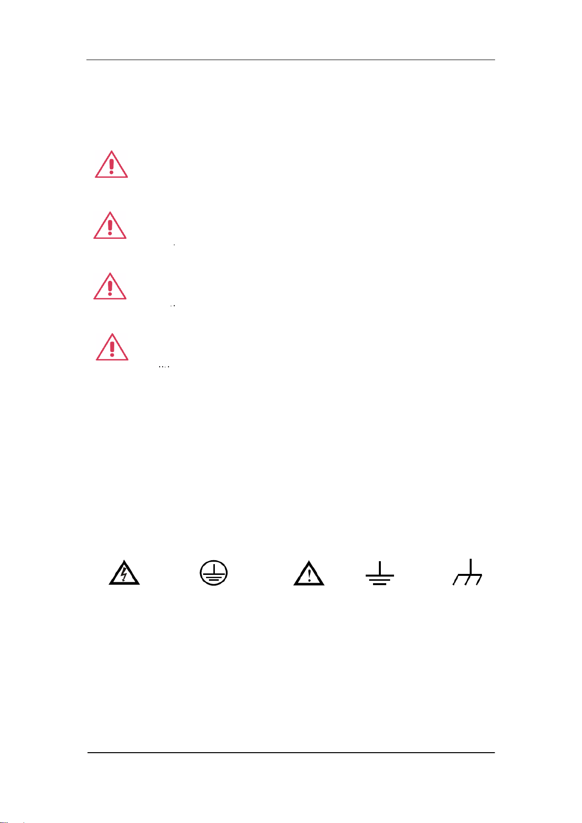
Symbols used on the instrument. Symbols may appear on the instrument.
WARNING: Warning statements indicate the conditions and
behaviors that could result in injury or loss of life.
CAUTION: Caution statements indicate the conditions and
behaviors that could result in damage to this product or other
properties.
CAT I (1000V): IEC Measurement Category I. The highest
measurable voltage is 1000Vpk in the HI-LO terminal.
properties.
CAT II (600V): IEC Measurement Category II. Inputs may be
connected to mains (up to 600VAC) under Category II overvoltage
conditions.
properties.
Hazardous
Voltage
Protective Earth
Ground
Warning
Test
Ground
Chassis
Ground

SIGLENT
VI SDM3065X Digital Multimeter
Daily Maintenance and Cleaning
Maintenance
When storing or placing the instrument, please avoid the liquid crystal display
from direct sunlight for a long time.
NOTE:
To avoid damages to the instrument or probe, please don‟t place them in mist,
liquid or solvent.
Cleaning
Please often clean the instrument or probe according to the use of them.
Wipe the external ash of the instrument and probe by a soft rag. Be
careful not to scratch the transparent plastic protective screen when cleaning
the liquid crystal screen.
Use a soft rag that has been soaked by water to clean the instrument
after cutting off the power. Or use 75% isopropyl alcohol of water solvent to
get a more thorough cleaning.
NOTE:
To prevent the surface of the instrument or probe from damages, please
don‟t use any corrosive or chemical cleaning reagents.
Please make sure the instrument is already dry before restarting it to
avoid short circuits or personal injuries caused by water.

SIGLENT
SDM3065X Digital Multimeter VII
Introduction of SDM3065X
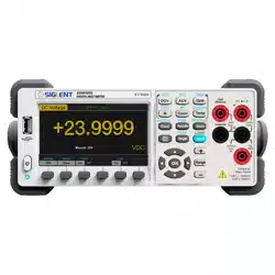
SDM3065X is a 6½ dual-display instrument, especially fitting to the needs of
high-precision, multifunction, and automation measurements. It realized a
combination of basic measurement functions, multiple math functions, and
display functions, etc.
SDM3065X holds a 4.3 inch color TFT-LCD display screen with 480*272 high
resolutions. Its clear keyboard layout and operation hints make it easier and
agility to use. Besides, it supports multi-interface such as USB Device & Host,
LAN and USB-GPIB (optional), which can meet users‟ demand furthest.
Main Features:
4.3 inch color TFT-LCD display screen with 480*272 high resolutions
Real 6½ digits readings resolution
Up to 150rdgs/S measurement speed
True-RMS AC Voltage and AC Current measurements
1 Gb Nand Flash size, mass storage configuration files and data files
Built-in cold terminal compensation for thermocouple
Support standard SCPI and control software on PC, compatible with
commands of main stream multimeters
Supports dual-display function, Chinese and English menu
Built-in help system, convenient to acquire information
Support USB Device, USB Host, LAN, and GPIB (only for SDM3065XA)
interfaces
Configuration and measured data can be imported or exported via VXI 11,
USBTMC and USB flash drive, which is convenient for users to modify,
view and backup

SIGLENT
VIII SDM3065X Digital Multimeter
Abstract
The manual mainly introduces corresponding information of operating the
SDM3065X Digital Multimeter. It contains these chapters:
Chapter 1 Quick Start
Guide you to prepare the SDM3065X Digital Multimeter and know about the
Front/Back panel and user interface.
Chapter 2 Function and Operation
Introduce the functions and operations of SDM3065X in details.
Chapter 3 Application Examples
Introduce you how to use strong measurement functions of this instrument
easily through some examples.
.
Chapter 4 General Troubleshooting
Provide you some general troubleshooting.
Chapter 5 Appendix
Provide you information about accessories, warranties, troubleshooting,
services and supports.

SIGLENT
SDM3065X Digital Multimeter IX
Content
Copyright and Statement .................................................................................. I
General Safety Summary ................................................................................. II
Safety Terms and Symbols ............................................................................. V
Daily Maintenance and Cleaning ................................................................... VI
Introduction of SDM3065X ............................................................................ VII
Abstract ........................................................................................................ VIII
Chapter 1 Quick Start .................................................................................. 1
General Inspection .................................................................................... 2
To adjust the Handle ................................................................................. 3
Appearance and Size................................................................................ 4
Front Panel ............................................................................................... 5
Back Panel ................................................................................................ 8
Start the Multimeter................................................................................. 11
User Interface ......................................................................................... 12
Measurement Connections ..................................................................... 13
To Use the Built-in Help System ............................................................. 16
Chapter 2 Function and Operation ............................................................ 17
Measurement Configuration .................................................................... 18
Range .............................................................................................. 19
Intergration Time and Resolution ..................................................... 21
DC Impedance ................................................................................. 23
Auto Zero ......................................................................................... 24
AC Filter ........................................................................................... 25
Short-circuit Resistance ................................................................... 26
Gate Time ........................................................................................ 27
Basic Measurement Functions ................................................................ 28
To Measure DC Voltage .................................................................. 29
To Measure DC Current .................................................................. 31
To Measure AC Voltage .................................................................. 33
To Measure AC Current ................................................................... 35
To Measure Resistance ................................................................... 37
To Measure Capacitance ................................................................. 40
To Measure Frequency or Period .................................................... 42
To Test Continuity............................................................................ 44
To Test Diode .................................................................................. 46
To Measure Temperature ................................................................ 48
Dual-display Function ............................................................................. 51
Utility Function ........................................................................................ 53
Store and Recall .............................................................................. 54
Manage File ..................................................................................... 58
I/O Configuration.............................................................................. 59
Board Test ....................................................................................... 61

SIGLENT
X SDM3065X Digital Multimeter
Firmware Update ............................................................................. 64
System Setup .................................................................................. 65
Acquire.................................................................................................... 67
Auto Trigger ..................................................................................... 68
Sample Count .................................................................................. 68
Single Trigger .................................................................................. 69
External Trigger ............................................................................... 70
Help System ........................................................................................... 71
Math Function ......................................................................................... 73
Statistics .......................................................................................... 75
Limits ............................................................................................... 77
dBm ................................................................................................. 79
dB .................................................................................................... 80
Relative Value.................................................................................. 81
Display Mode .......................................................................................... 82
Trigger .................................................................................................... 88
Hold Measurement Function ................................................................... 89
Chapter 3 Measurement Tutorial ............................................................... 90
True RMS AC Measurement ................................................................... 90
Crest Factor Errors (non-sinusoidal inputs) ............................................ 91
Loading Errors (AC Voltage) ................................................................... 92
Chapter 4 General Troubleshooting .......................................................... 93
Chapter 5 Appendix ................................................................................... 94
Appendix A: Accessories ........................................................................ 94
Appendix B: Warranty summary ............................................................. 95
Appendix C: Contact SIGLENT ............................................................... 96

SIGLENT
SDM3065X Digital Multimeter 1
Chapter 1 Quick Start
This chapter guides users to quicky get familar with the front and rear panles,
user interface and measurement connections of the multimeter.
This chapter contains the following topics:
General Inspection
Handle Adjustment
Appearance and Size
The Front Panel
The Back Panel
Start the Multimeter
User Interface
Measurement Connections
To Use the Built-in Help System

SIGLENT
2 SDM3065X Digital Multimeter
General Inspection
1. Inspect the shipping container.
Please keep the damaged container or cushioning material until the contents
of the shipment have been checked for completeness and the instrument has
passed both electrical and mechanical tests.
The consigner or carrier shall be liable for the damage to instrument resulting
from shipment. SIGLENT would not be responsible for free maintenance/
rework or replacement of the unit.
2. Inspect the instrument.
In case of any damage, or defect, or failure, notify your SIGLENT sales
representative.
3. Check the accessories.
Check the accessories according to the packing list. If the accessories are
incomplete or damaged, please contact your SIGLENT sales representative.
SIGLENT
SDM3065X Digital Multimeter 3
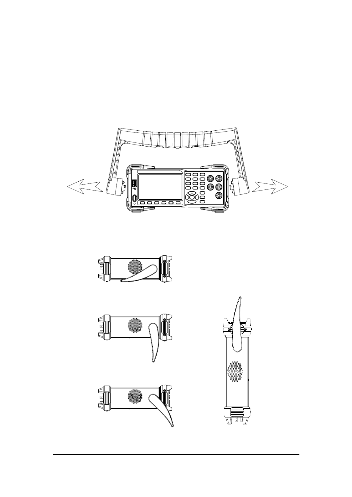
To adjust the Handle
Adjust the handle position of SDM3065X properly to place the instrument
stably so that users can manipulate and observe the display better. Please grip
the handle by the two sides and pull it outward. Then rotate the handle to the
appropriate position. Please operate as the following diagram.
Diagram 1- 1 Handle adjustment
Diagram 1- 2 Horizontal Position Diagram 1- 3 Carrying Position
SIGLENT
4 SDM3065X Digital Multimeter
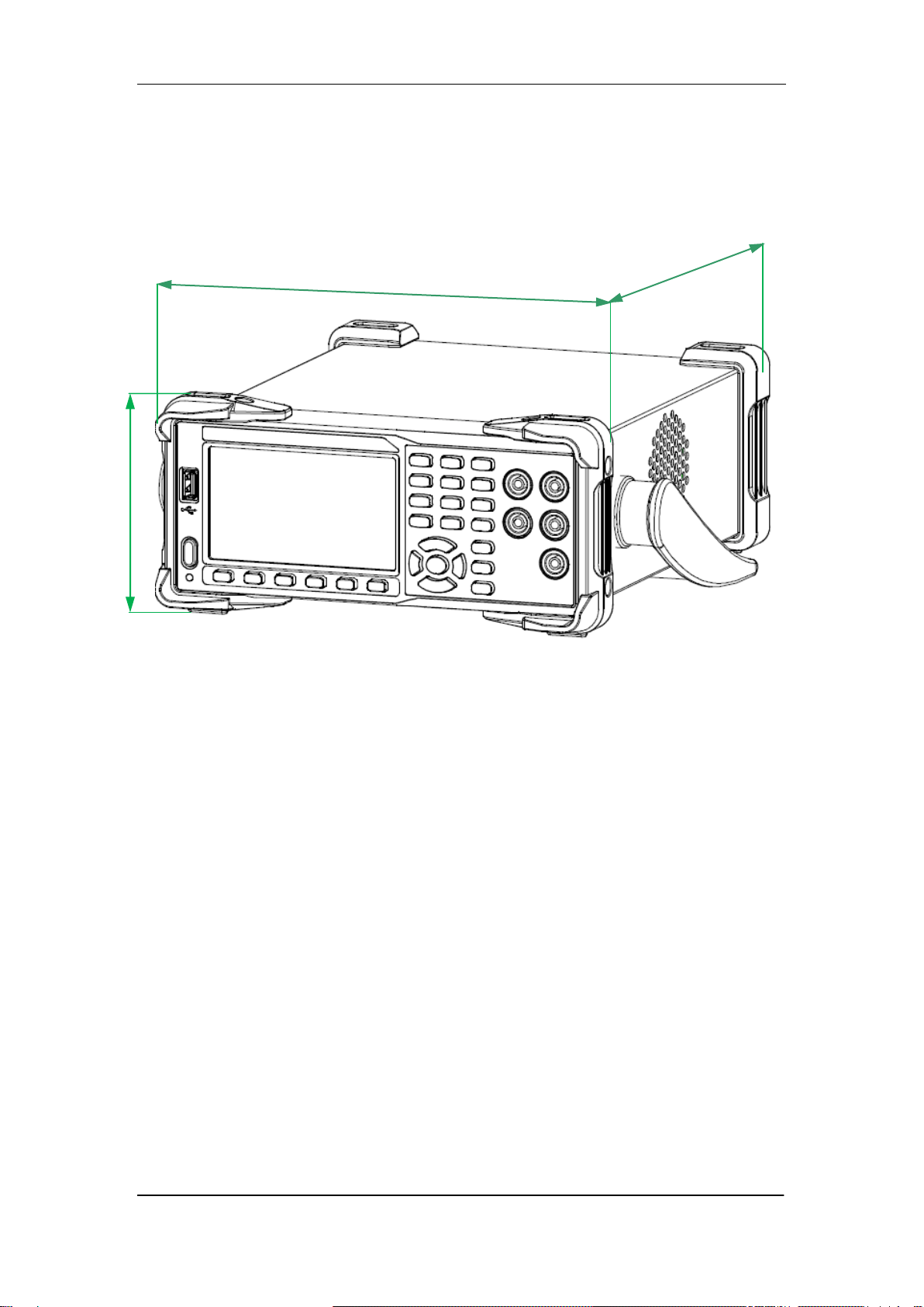
Appearance and Size
Diagram 1- 4 Appearance and Size
260 .27mm
107.21 mm
293.75mm
SIGLENT
SDM3065X Digital Multimeter 5
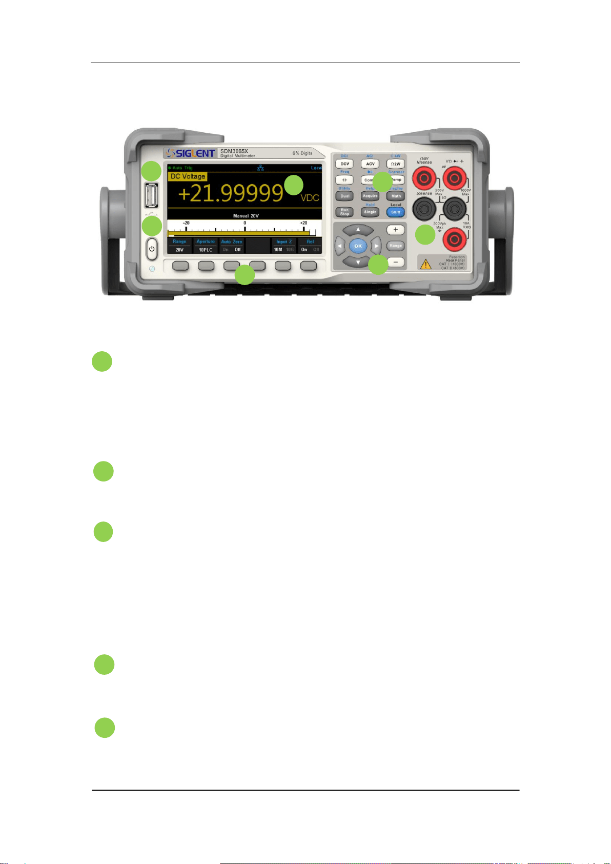
Front Panel
Diagram 1- 5 Front Panel Overview
USB Host
By using this interface, users can store the current state or
measurement data into USB storage device. Users can also read the
state files or updated firmware from USB storage device.
Power Key
Long/short press the key to turn on/off the instrument.
LCD Display
The instrument provides a 4.3 inch color TFT-LCD display screen with
480*272 high resolutions that can the current function menus,
measurement parameter settings, system status, prompt messages and
so on.
Menu Operation Keys
Press any softkey to activate the corresponding menu.
Measurement and Assistant Function Keys
B
A
H
B
C
D
E
F
B
G
B
C
D
E
A
H
B
B
SIGLENT
6 SDM3065X Digital Multimeter
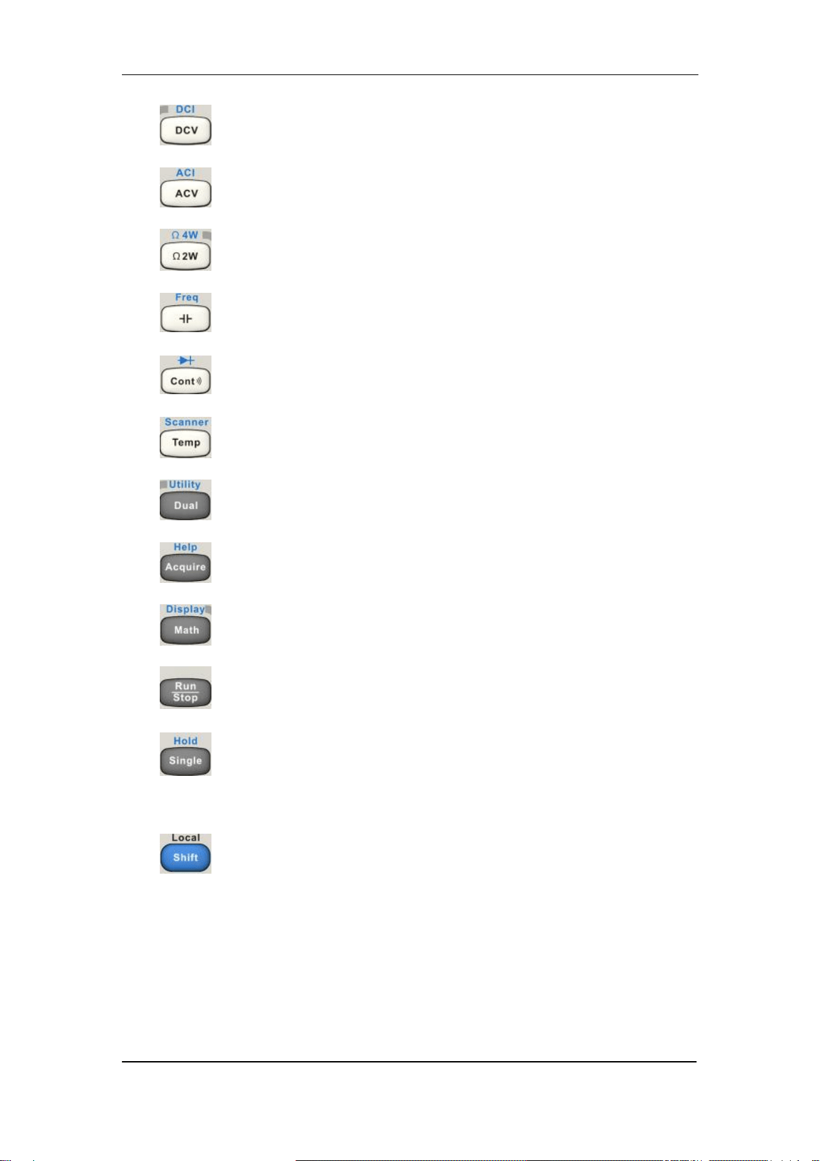
DC Voltage /Current Measurement
AC Voltage/ Current Measurement
2-Wire /4-Wire Resistance Measurement
Frequency /Capacitance Measurement
Continuity /Diode Test
Temperature Measurement/
Enable Multiple Scan Card Function
Enable Dual-display Function /Set Up the Utility
Acquire Function /Help System
Math Function /Display Function
Auto Trigger/ Stop
Single Trigger/ Hold Measurement Function
Return to local control of the instrument (when in
Remote mode).
Some of the front panel keys have text above
them. This indicates that the key has a function
that you can access by pressing and releasing
[Shift] before pressing the key.
SIGLENT
SDM3065X Digital Multimeter 7
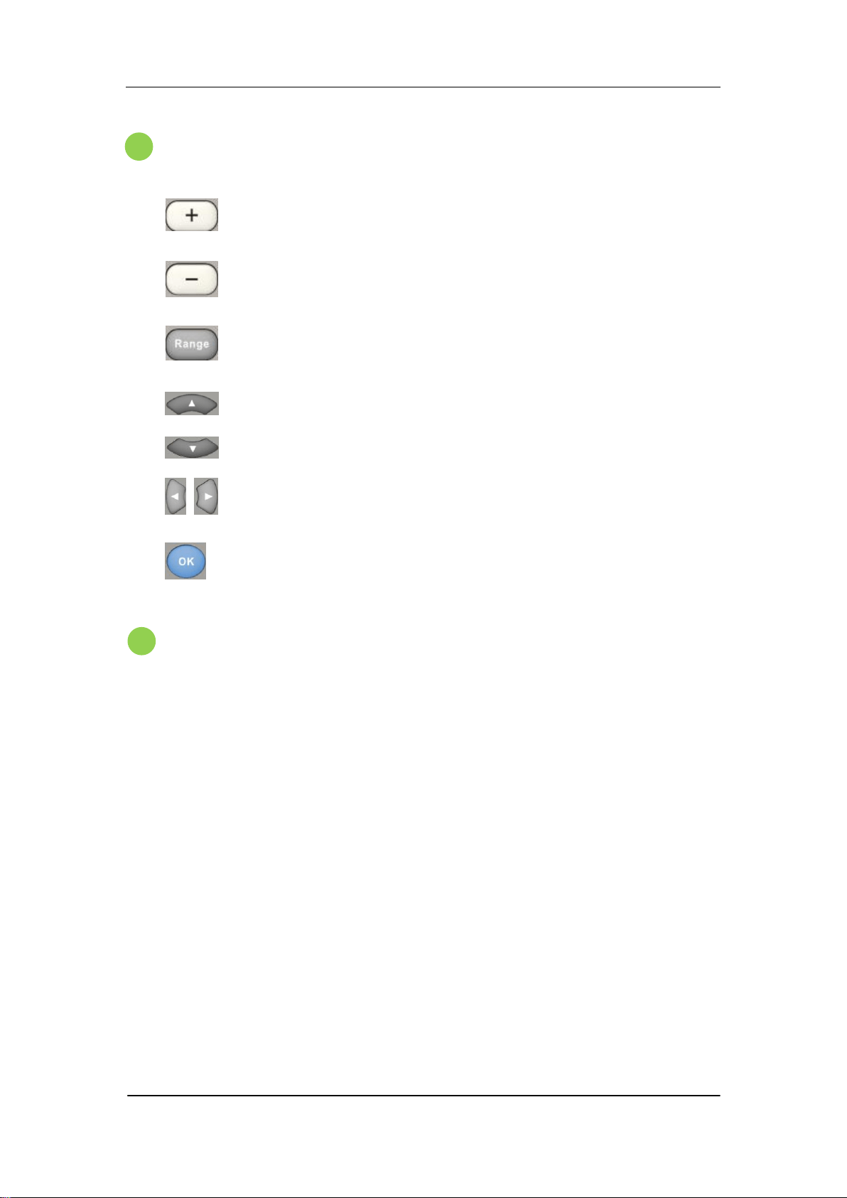
Range and Direction Keys
Increase the measurement range
Decrease the measurement range
Select auto or manual range
Set up measurement parameter
Move the cursor
Page or down
Set up measurement parameter
Move the cursor
Apply the current setting
Signal Input Terminals
The measured signal (device) will be connected into the multimeter
through these terminals. Different measurement objects have different
connection methods. For details, please refer to “Measurement
Connections”.
G
B
F
B
SIGLENT
8 SDM3065X Digital Multimeter
Back Panel
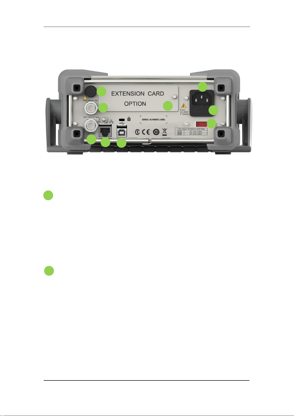
Diagram 1- 6 Back Panel Overview
Power Socket
The multimeter accepts two types of AC supplies. Please use the
power cord provided in the accessories to connect the multimeter to the
AC power through this socket.
Note: a proper voltage scale must be first selected (through the Voltage
Selector) before power connection.
Power Fuse
The multimeter is already installed with a power fuse before leaving
factory. To replace a new one, please:
1) Turn off the multimeter and remove the power cord.
2) Press down the block tongue using a straight screwdriver (in the
direction of the dotted arrow in the figure below) and pull out of the
fuse seat.
3) Select a proper voltage scale.
4) Replace a specified fuse.
5) Reinstall the fuse seat into the slot.
I
B
G
B
H
B
F
B
E
A
H
B
B
C
D
A
H
B
B

SIGLENT
SDM3065X Digital Multimeter 9
Diagram 1- 7 Change the fuse
AC Voltage Selector
Select a proper voltage scale (110 V or 220 V) according to the AC
supply used.
Inspection card
(option)
An optional 16-channel Data Acquisition Module can be installed in
the instrument.
USB Device
Connect the PC through this interface. You can use SCPI commands
or PC software to control SDM3065X remotely.
LAN
Through this interface, the multimeter can be connected to the
network for remote control.
VMC Output
The mutlimeter outputs a low-true pulse from the [VM Comp]
connector after every measurement
Ext trigger
Trigger the multimeter by connecting a trigger pulse through the [Ext
E
G
B
F
B
D
H
B
C

SIGLENT
10 SDM3065X Digital Multimeter
Trig] connector. Note the external trigger source must be selected.
Current Input Fuse
The multimeter is already installed with a current Input fuse to provide
10 A maximum input protection before leaving factory. To replace a
new one, please:
1) Turn off the multimeter and remove the power cord.
2) Turn the fuse seat counterclockwise as shown in the
figure using a straight screw driver and then pull out the fuse seat
3) Place a new specified fuse.
4) Reinstall the fuse seat into the slot.
Instrument Lockhole
You can use the safety lock to lock the multimeter in a fixed place if
necessary.
I
B
J
SIGLENT
SDM3065X Digital Multimeter 11
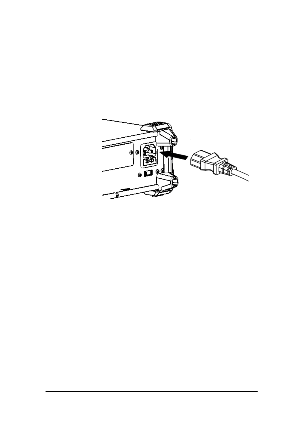
Start the Multimeter
Before connect the instrument to a power source, please select the AC
voltage selector on the rear panel of your multimeter according to the power
supply.Then connect the power cord as shown in the following figure.
Diagram 1- 8 Connect Power Cord
Press the Power key on the front panel to start up the multimeter. If the
multimeter does not starts normally, please:
1. Make sure the power cord is in good connection.
2. Try to restart the multimeter, if it fails, check the power fuse
and replace a new one when necessary.
3. If the problem still remains, please contact SIGLENT.
SIGLENT
12 SDM3065X Digital Multimeter
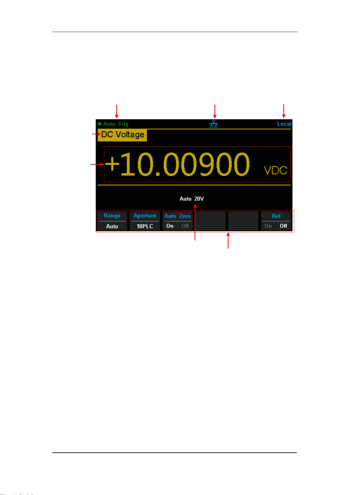
User Interface
Diagram 1- 9 User Interface
Measureme
t
Function
Measureme
t
Result
Trigger
Mode
Control Mode
LAN Status Icon
Range
Operation Menu
SIGLENT
SDM3065X Digital Multimeter 13
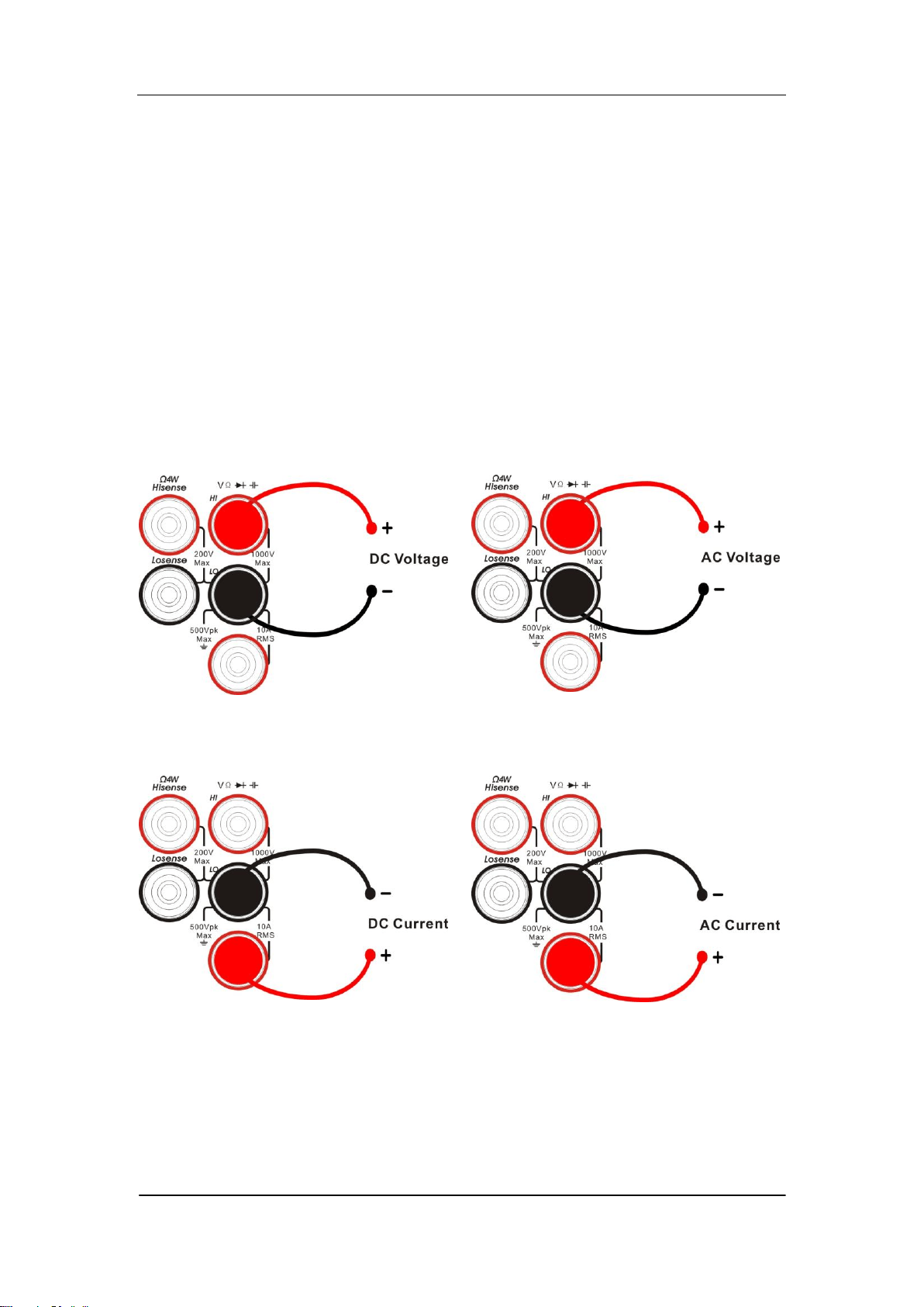
Measurement Connections
SDM3065X is designed with many measurement functions. After selecting
the desired measurement function, please connect the signal (device) under
test to the multimeter according to the method below. Do not discretionarily
switch the measurement function when measuring as it may cause damage
to the multimeter. For example, when the test leads are connected to the
related current terminals, AC voltage measurement should not be taken.
DCV Measurement ACV Measurement
DCI Measurement ACI Measurement
SIGLENT
14 SDM3065X Digital Multimeter
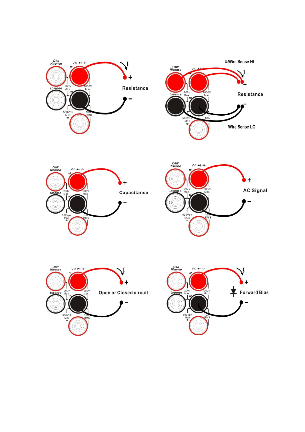
Resistance Measurement (2-wire) Resistance Measurement
(2-wire)
Capacitance Measurement Frequency/Period Measurement
Continuity Measurement Diode Measurement
SIGLENT
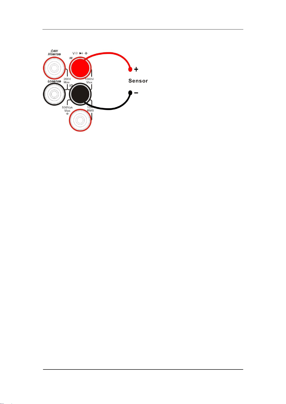
SDM3065X Digital Multimeter 15
Temperature Measurement
(For RTD and thermcouple sensors)

SIGLENT
16 SDM3065X Digital Multimeter
To Use the Built-in Help System
To obtain built-in help information of the product, please press 【shift】+
【Acquire】to enter help system, then use the direction keys to choose the help
item you want, finally press 【OK】to obtain help information
The common help information is listed as the following:
1. Basic Measure.
2. Measuring Temperature.
3. Measuring Capacitance.
4. Math Function.
5. Dual-display Function.
6. Saving and Recalling Information.
7. Optional Multiple Scan Card.
8. The convention and Tips of Softkeys.
9. Technical Support.

SIGLENT
SDM3065X Digital Multimeter 17
Chapter 2 Function and Operation
This chapter introduces how to use the functions of the multimeter from the
front panel. The chapter contains the following topics:
To Set the Range
To Set the Resolution
Basic Measurement Functions
Any Sensor Measurement
Preset Mode
Secondary Function Key
Measurement Configuration
Math Operations
Trigger
Save and Recall
Utility
SIGLENT
18 SDM3065X Digital Multimeter
Measurement Configuration
Most measurement parameters are user-defined. Changing a measurement
parameter will change the measurement precision and speed as well as the
input impedance. An appropriate measurement parameter based on the actual
application will ensure faster measurement or higher measurement precision.
The default measurement configurations of the multimeter can ensure the
accuracy of the measurement results in most cases. Users can directly use
these defaults for any measurement or modify the parameters of the
measurement function as required.
The parameters for different measurement function differ, see table below.
Table 2-1 Measurement parameter
Functions
Parameters
DCV
Range, Integration Time, DC impedance, Auto zero
ACV
Range, AC filiter
DCI
Range, Integration Time, Auto zero
ACI
Range, AC filiter
OHM(2WR、4WR)
Range, Integration Time, Auto zero
CAP
Range
CONT
Short-circuit resistance
DIODE
Breakover voltage
FREQ/PREIOD
Gate time
TEMP
N/A
SIGLENT
SDM3065X Digital Multimeter 19
Range
SDM3065X provides auto and manual range selecting modes. In auto mode,
the multimeter selects a proper range automatically according to the input
signal; in manual mode, you can use the front panel key or menu key to set the
range. The auto mode can bring a lot of convenience for users while the
manual mode provides higher reading precision.
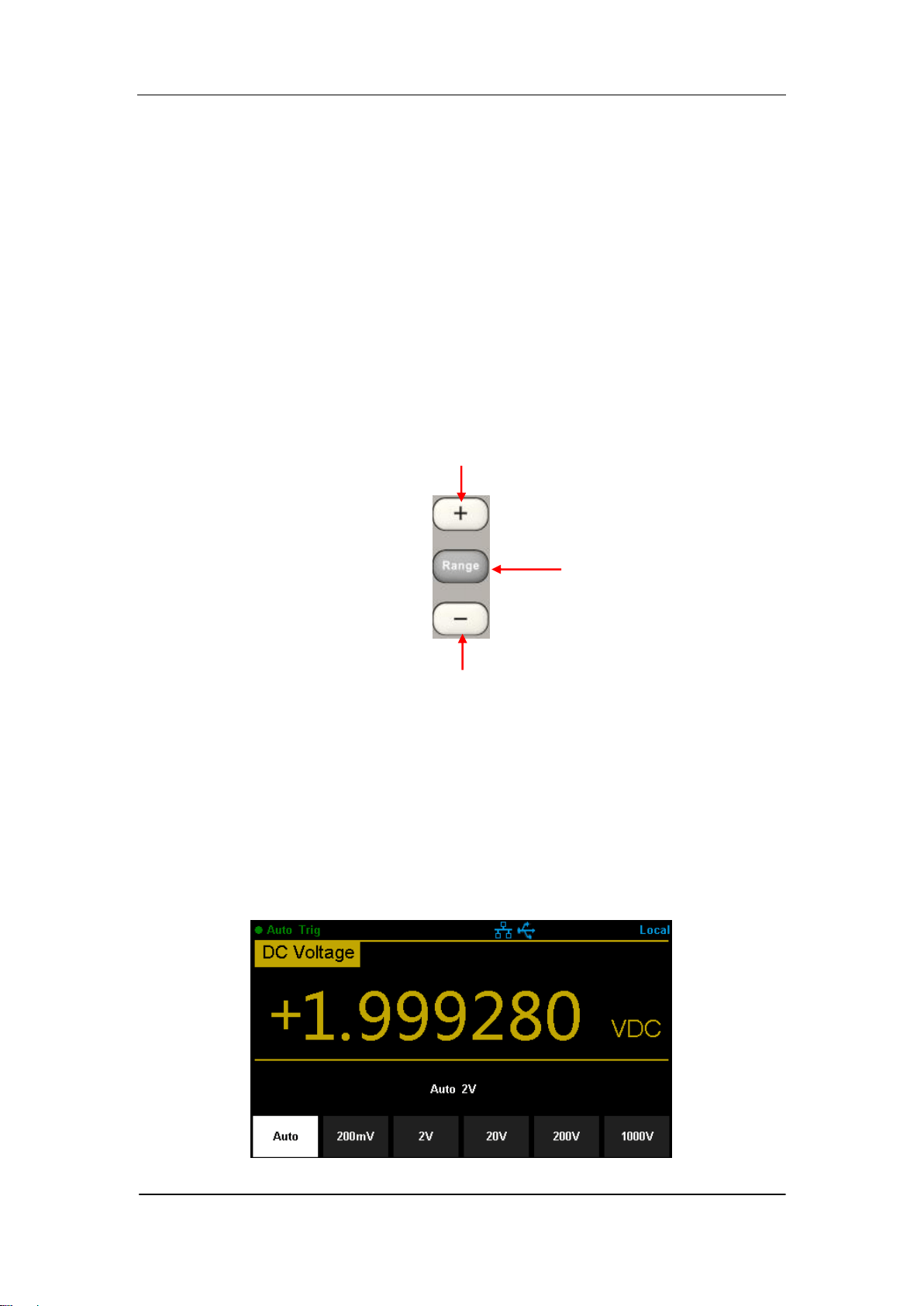
Method 1: use the front panel key to set the range
Manual Range, to increase range
Manual Range, to decrease range
Diagram 2- 1 Range Selection Keys
Method 2: use the menu key to select the range
Enter the specific measurement function and select 【Range】in the menu to
show the range setting options, as shown in Diagram 2-2 ( take DCV
measuremt for instance). Then press the menu operation key to activate the
corresponding configuration.
Diagram 2- 2 Range selection menu
To switch modes between
Auto Range and Manual
Range

SIGLENT
20 SDM3065X Digital Multimeter
Note:
1. “overload” will be displayed when the input signal exceeds the current
range.
2. By default, the range is set to Auto at power-on or after a reset.
3. Auto mode is recommended if you are not sure about the measurement
range in order to protect the instrument and obtain accurate data.
4. The range of CONT measurement is fixed at 2 kΩ.
SIGLENT
SDM3065X Digital Multimeter 21
Intergration Time and Resolution
Integration time is the period during which the multimeter‟s analog-to-digital
(A/D) converter samples the input signal for a measurement. The longer the
integration time is, the slower the measurement speed will be and the higher
the resolution will be; the shorter the integration time is, the faster the
measurement will be and the lower the resolution will be. The integration time
applies to DCV, DCI, 2WR and 4WR measurements.
SDM3065X express the integration time by the power line cycles, the unit is
PLC. The multimeter automatically detects the input power frequency at
power-on. I f the frequency is 50Hz, the intergration time can be set to
0.005PLC, 0.05 PLC, 0.5 PLC, 1 PLC, 10 PLC, 100 PLC and the default is 10
PLC. If the frequency is 60Hz, the intergration time can be set to 0.006PLC,
0.06 PLC, 0.6 PLC, 1 PLC, 10 PLC, 100 PLC and the default is 10 PLC .
SDM3065X holds reading resolutions of 4½ , 5½ and 6½ digits. It automatically
selects a reading resolution according to the current measurement settings.
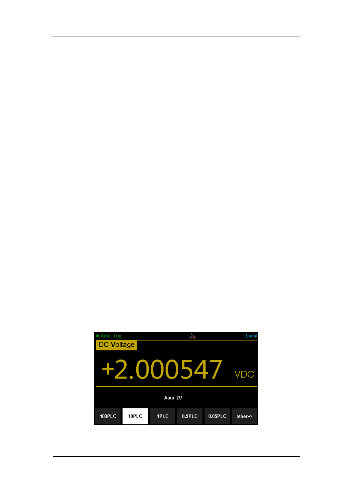
1. In DCV, DCI and OHM measurements, press 【Aperture】 to set the
intergration time, as shown in Diagram 2-5 (take DCV measurement for
instance). The integration time affects the resolution.
Diagram 2- 3 Intergration time selection menu

SIGLENT
22 SDM3065X Digital Multimeter
Table 2-2 Relationship between reading resolution and integration time
Resolution
Intergration time
4½
0.005 PLC / 0.006PLC
0.05 PLC / 0.06PLC
5½
0.5 PLC / 0.6PLC
6½
1 PLC
10 PLC
100 C
2. In ACV, ACI ,FREQ/PERIOD measurements, the resolution is fixed at 6½
digits.
3. In CAP measurements, the resolution is fixed at 4½
4. The instrument always displays 2 digit after the decimal point in CONT
measurement.
5. In DIODE measurements, the resolution is fixed at 5½ .
6. In TEMP measurements, the resolution is fixed at 5½ .
SIGLENT
SDM3065X Digital Multimeter 23
DC Impedance
DC impedance applies to DCV measurement. The default is “10MΩ”. In the
range of 200 mV, 2 V or 20 V, you can choose “>10GΩ” to reduce the loading
error to the measured object caused by the multimeter
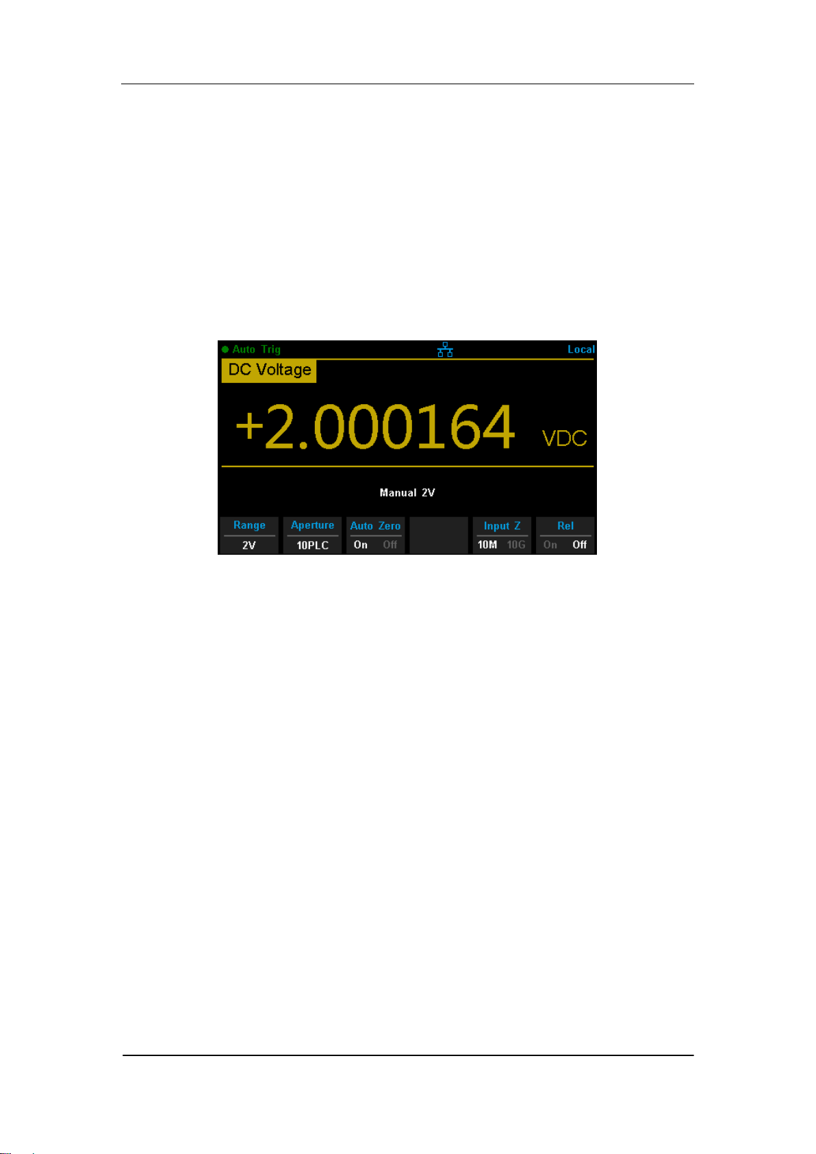
In the range of 200 mV, 2 V or 20 V under DCV measurement, press 【Input Z】
in the menu to perform the setting, as shown in Diagram 2-4.
Diagram 2-4 Choose DC Input Impedance
10MΩ: set the input impedances in all ranges to 10 MΩ.
10GΩ: set the input impedances in ranges of 200 mV, 2 V and 20 V to 10
GΩ, while in ranges of 200 V and 1000 V, the impedances are still
10 MΩ.
SIGLENT
24 SDM3065X Digital Multimeter
Auto Zero
Auto zero (Auto Zero) applies to DCV, DCI, 2WR and 4WR measurements.
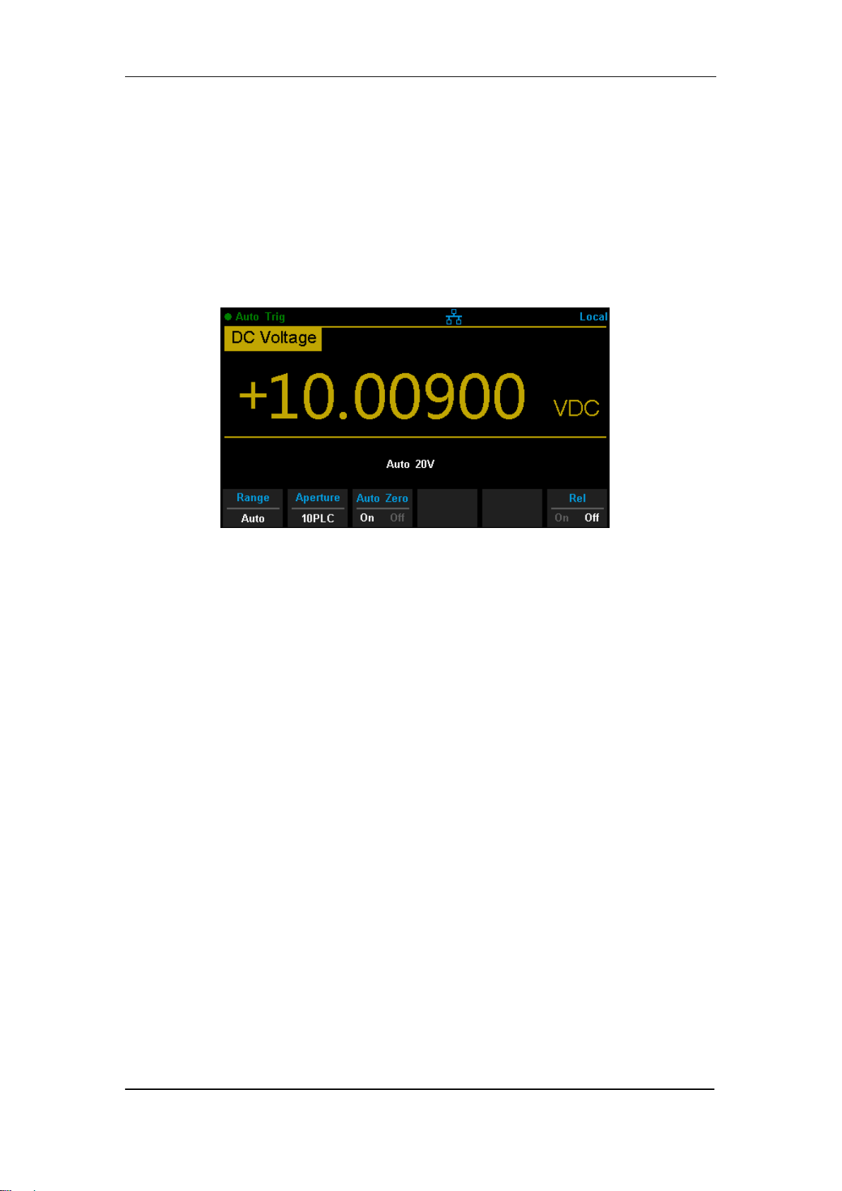
Enter the specific measurement function and press【Auto Zero】in the menu
to perform the setting, as shown in Diagram 2-5 (take DCV measurement for
instance).
Diagram 2-5 Turn on or off Auto Zero
ON: the multimeter internally disconnects the input signal and measured
circuit after each measurement, and takes a zero reading. It then
subtracts the zero reading from the preceding reading (displaying the
difference between the measurement value and zero value during the
measurement), in order to reduce the impact of offset voltage from input
circuit on measurement result.
OFF:disable the auto zero function.
SIGLENT
SDM3065X Digital Multimeter 25
AC Filter
AC filter applies to ACV and ACI measurements. It can optimize the
low-frequency accuracy and minimize the AC settling time. SDM3065X
provides three types of AC filters (>3Hz, >20Hz, >200Hz).
The AC filter to be used is determined by the input signal frequency. You
should generally select the highest frequency filter whose frequency is less
than that of the signal you are measuring, because higher frequency filters
result in faster measurements. For example, when measuring a signal
between 20 and 200 Hz, use the 20 Hz filter. If measurement speed is not an
issue, choosing a lower frequency filter may result in quieter measurements,
depending on the signal that you are measuring.
Press 【Filter】in the menu of ACV or ACI measurement to show the setting
options, as shown in Diagram 2-6 (take ACV measurement for instance).
Then press the menu operation key to activate the corresponding
configuration.
Diagram 2-6 AC Filter setting interface
SIGLENT
26 SDM3065X Digital Multimeter
Short-circuit Resistance
This function only applies to continuity test. When the measured circuit has a
resistance lower than the short-circuit resistance, the circuit is considered as
connected, and the beeper sounds (if sound is on). The default short-circuit
resistance is 50 Ω and the setting is stored in nonvolatile memory.
When continuity test is enabled, Set the 【Threshold】(equal to short-circuit
resistance) using the direction keys. The range is from 1 Ω to 2000 Ω .
Diagram 2- 7 Set Up the Short-circuit Resistance
SIGLENT
SDM3065X Digital Multimeter 27
Gate Time
Gate time (also called Aperture Time) applies to FREQ/PERIOD function. It
decides the resolution of low-frequency measurement. The longer the gate
time is, the higher the resolution of the low-frequency measurement is and
the slower the measurement is, and vice versa.
In FREQ/PERIOD measurement, press 【Gate Time】to show the setting
options, as shown in Diagram 2-8 (take FREQ measurement for instance).
The gate time can be set to 1 ms, 10 ms, 100 ms or 1 s and the default is 100
ms. You can select a desired gate time by pressing the corresponding
softkey.
Diagram 2- 8 Set Up the Gate Time

SIGLENT
28 SDM3065X Digital Multimeter
Basic Measurement Functions
SDM3065X Digital Multimeters have following basic functions:
To Measure DC Voltage
To Measure AC Voltage
To Measure DC Current
To Measure AC Current
To Measure 2/4-Wire Resistance
To Measure Capacitance
To Test Continuity
To Test Diode
To Measure Frequency or Period
To Measure Temperature

SIGLENT
SDM3065X Digital Multimeter 29
To Measure DC Voltage
Range: 200mV, 2V, 20V, 200V, 1000V
Max Resolution: 100nV (in the range of 200mV)
Input Protection: a 1000 V protection is available in all ranges and a 10%
overrange for all ranges except 1000 V range. If the reading exceeds the
range, “overload” will be displayed.
Operating Steps:
1. Enable the DCV measurement
Press on the front panel to enter the DC Voltage measurement
interface, as shown in Diagram 2- 9.
Diagram 2- 9 DC Voltage Measurement Interface
2. Make connection
Connect the test leads with the measured signal by referring to
“Measurement Connections”.
3. Set the range
Press 【Range】to select a range for the measurement. You can also use
the , , and keys on the front panel to select the range.
Auto (autorange) automatically selects the range for the measurement
based on the input. Autoranging is convenient, but it results in slower
measurements than using a manual range. Autoranging goes up a range
at 110% of the present range, and down a range below 10% of the
present range.
4. Set the intergration

SIGLENT
30 SDM3065X Digital Multimeter
Press 【Aperture】and choose the number of power-line cycles (PLCs) to
use for the measurement. Selecting 100 PLC provides the best noise
rejection and resolution, but the slowest measurements
5. Autozero setting
Press 【Auto Zero】to enable or disable this function. Autozero provides the
most accurate measurements, but requires additional time to perform the
zero measurement.With autozero enabled (On), the DMM internally
measures the offset following each measurement. It then subtracts that
measurement from the preceding reading. This prevents offset voltages
present on the DMM‟s input circuitry from affecting measurement accuracy.
6. Specify the DC input impedance (Only for Manual 200mV,2V and 20V
ranges)
Press 【Input Z】to set the DC resistance as “10M” (default value) or
“10G”. Users can execute DC voltage measurement directly without
modifying this parameter which has been setup before leaving factory.
7. Set the relative value (Optional operation)
Press 【Rel】 to open or close Relative math function. When it is opened,
the reading displayed is a value which comes from the result of actual
measurement value subtracts the relative value that has been set. The
default relative value is the measurement value when the function is
opened.(Please refer to “ Math Functions” in Chapter 2 to know about the
details.)
8. Read the measurement value
The multimeter measures the input signal according to the current
measurement settings and displays the measurement result on the
screen.
9. Make math operation (advanced)
You can perform math operation (Statistics, Limit, dBm, dB and REL) on
every DCV measurement reading. For details, please refer to “Math
Operations”.
10. Display the graph (advanced)
You can analyze the measurement data by using “Bar Meter”, “Trend
Char” or “Histogram display”. For details, please refer to “Display Mode”.
SIGLENT
SDM3065X Digital Multimeter 31
To Measure DC Current
Range: 200μA, 2 mA, 20 mA, 200 mA, 2A, 10A
Max Resolution: 0.1nA (in the range of 200μA)
Input Protection: a 10A protection is available in all ranges and a 10%
overrange for all ranges except 10A range. If the reading exceeds the
range, “overload” will be displayed.
Operating Steps:
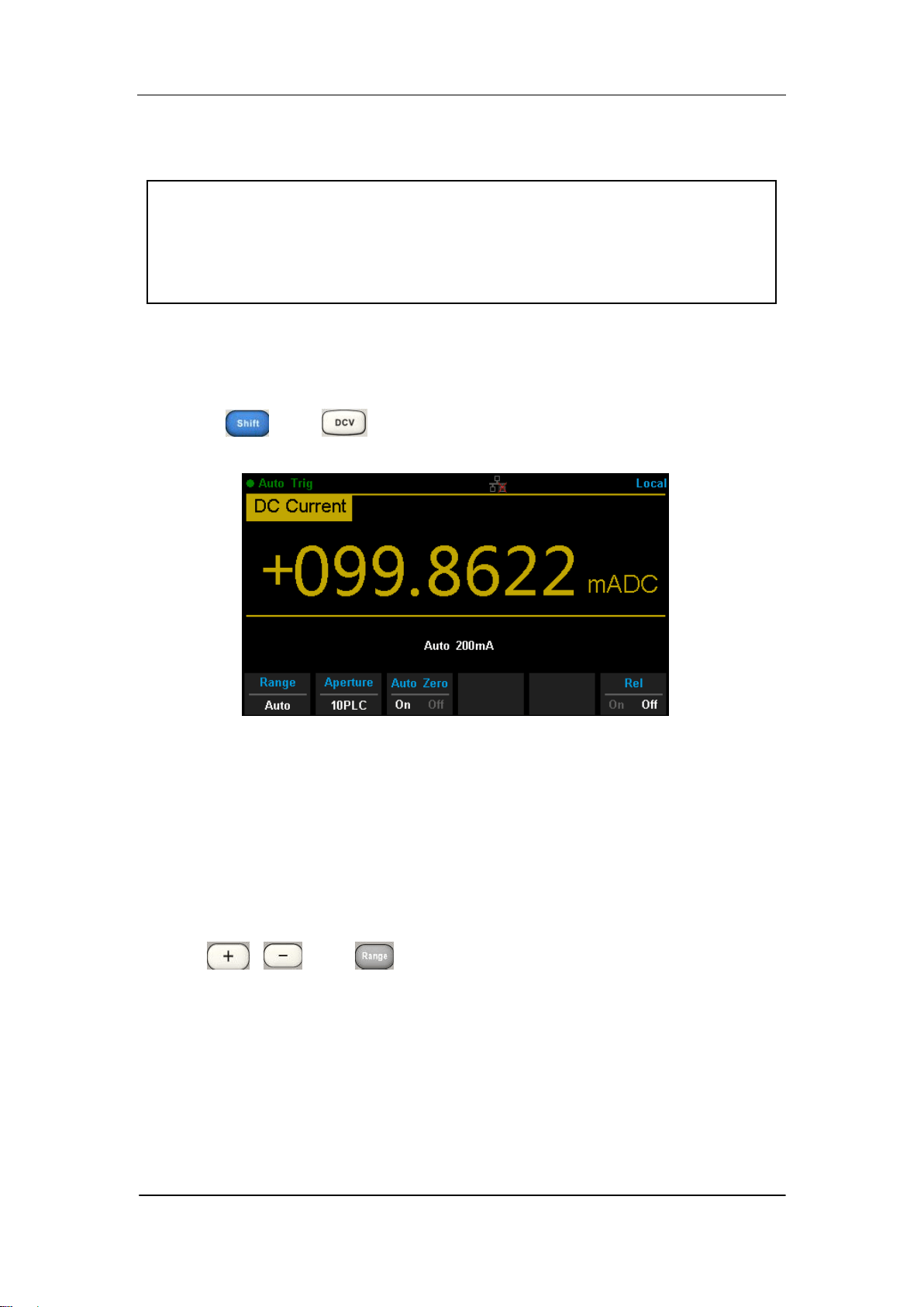
1. Enable the DCI measurement
Press and on the front panel to enter the DC Current
measurement interface, as shown in Diagram 2- 10.
Diagram 2- 10 DC Current Measurement Interface
2. Make connection
Connect the test leads with the measured signal by referring to
“Measurement Connections”.
3. Set the range
Press 【Range】to select a range for the measurement. You can also use
the , , and keys on the front panel to select the range.
Auto (autorange) automatically selects the range for the measurement
based on the input. Autoranging is convenient, but it results in slower
measurements than using a manual range. Autoranging goes up a range
at 110% of the present range, and down a range below 10% of the
present range.
4. Set the intergration Time

SIGLENT
32 SDM3065X Digital Multimeter
Press 【Aperture】and choose the number of power-line cycles (PLCs) to
use for the measurement. Selecting 100 PLC provides the best noise
rejection and resolution, but the slowest measurements
5. Autozero setting
Press 【Auto Zero】to enable or disable this function. Autozero provides the
most accurate measurements, but requires additional time to perform the
zero measurement.With autozero enabled (On), the DMM internally
measures the offset following each measurement. It then subtracts that
measurement from the preceding reading. This prevents offset voltages
present on the DMM‟s input circuitry from affecting measurement accuracy.
6. Set the relative value (Optional operation)
Press 【Rel】 to open or close Relative math function. When it is opened,
the reading displayed is a value which comes from the result of actual
measurement value subtracts the relative value that has been set. The
default relative value is the measurement value when the function is
opened.(Please refer to “ Math Functions” in Chapter 2 to know about the
details.)
7. Read the measurement value
The multimeter measures the input signal according to the current
measurement settings and displays the measurement result on the
screen.
8. Make math operation (advanced)
You can perform math operation (Statistics, Limit and REL) on every DCI
measurement reading. For details, please refer to “Math Operations”.
9. Display the graph (advanced)
You can analyze the measurement data by using “Bar Meter”, “Trend
Char” or “Histogram display”. For details, please refer to “Display Mode”.
SIGLENT
SDM3065X Digital Multimeter 33
To Measure AC Voltage
Range: 200mV, 2V, 20V, 200V, 750V
Max Resolution: 100nV (in the range of 200mV)
Input Protection: a 750 V protection is available in all ranges and a 10%
overrange for all ranges except 750 V range. If the reading exceeds the
range, “overload” will be displayed.
Operating Steps:
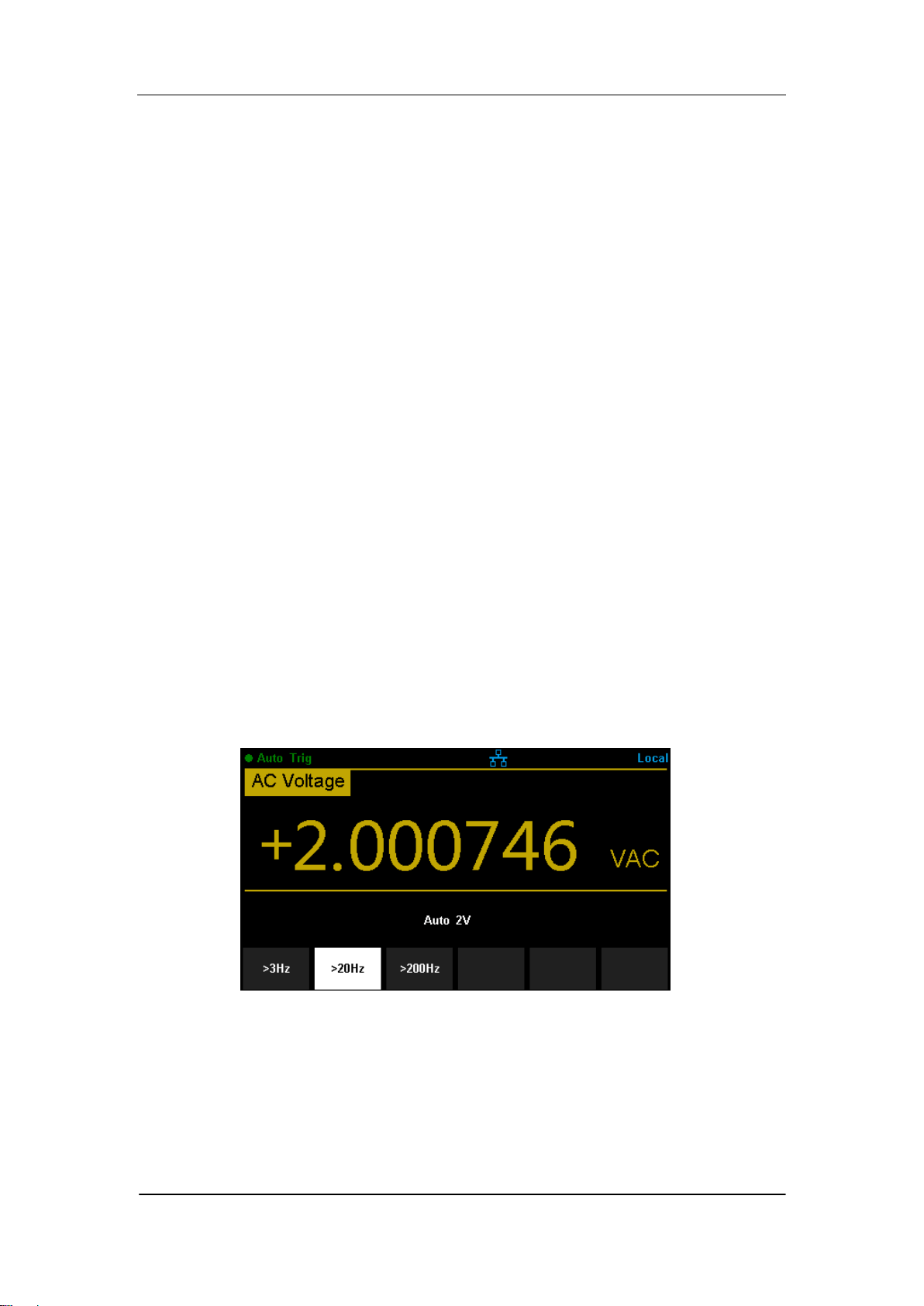
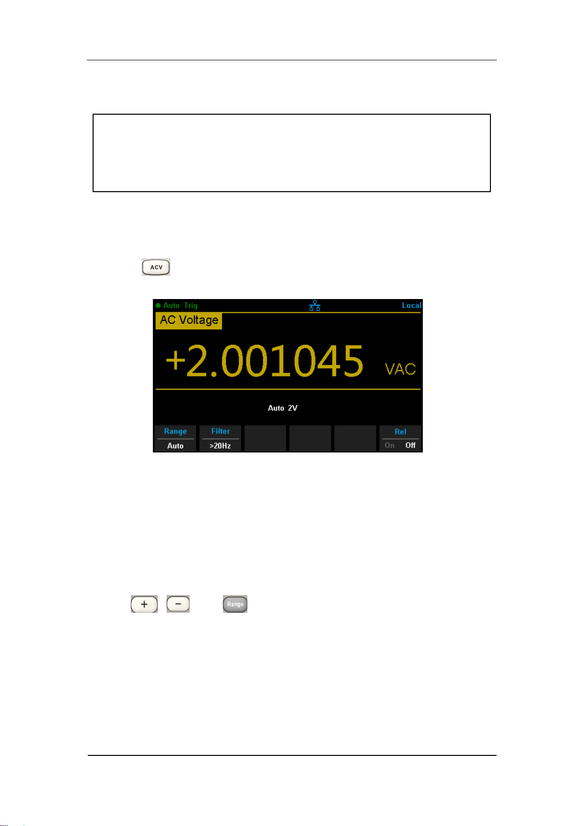
1. Enable the ACV measurement
Press on the front panel to enter the AC Voltage measurement
interface, as shown in Diagram 2- 11.
Diagram 2- 11 AC Voltage Measurement Interface
2. Make connection
Connect the test leads with the measured signal by referring to
“Measurement Connections”.
3. Set the range
Press 【Range】to select a range for the measurement. You can also use
the , , and keys on the front panel to select the range.
Auto (autorange) automatically selects the range for the measurement
based on the input. Autoranging is convenient, but it results in slower
measurements than using a manual range. Autoranging goes up a range
at 110% of the present range, and down a range below 10% of the
present range.
4. Set the filter

SIGLENT
34 SDM3065X Digital Multimeter
Press【Filter】and choose the filter for the measurement. The instrument
provides three different AC filters --“>3Hz”, “>20Hz” and “>200Hz”. You
should generally select the highest frequency filter whose frequency is less
than that of the signal you are measuring,
5. Set the relative value (Optional operation)
Press 【Rel】 to open or close Relative math function. When it is opened,
the reading displayed is a value which comes from the result of actual
measurement value subtracts the relative value that has been set. The
default relative value is the measurement value when the function is
opened.(Please refer to “ Math Functions” in Chapter 2 to know about the
details.)
6. Read the measurement value
The multimeter measures the input signal according to the current
measurement settings and displays the measurement result on the
screen.
7. Make math operation (advanced)
You can perform math operation (Statistics, Limit, dBm, dB and REL) on
every ACV measurement reading. For details, please refer to “Math
Operations”.
8. Display the graph (advanced)
You can analyze the measurement data by using “Bar Meter”, “Trend Char” or
“Histogram display”. For details, please refer to “Display Mode”.
SIGLENT
SDM3065X Digital Multimeter 35
To Measure AC Current
Range: 200μA, 2 mA, 20 mA, 200 mA, 2A, 10A
Max Resolution: 0.1nA (in the range of 200μA)
Input Protection: a 10A protection is available in all ranges and a 10%
overrange for all ranges except 10A range. If the reading exceeds the
range, “overload” will be displayed.
Operating Steps:
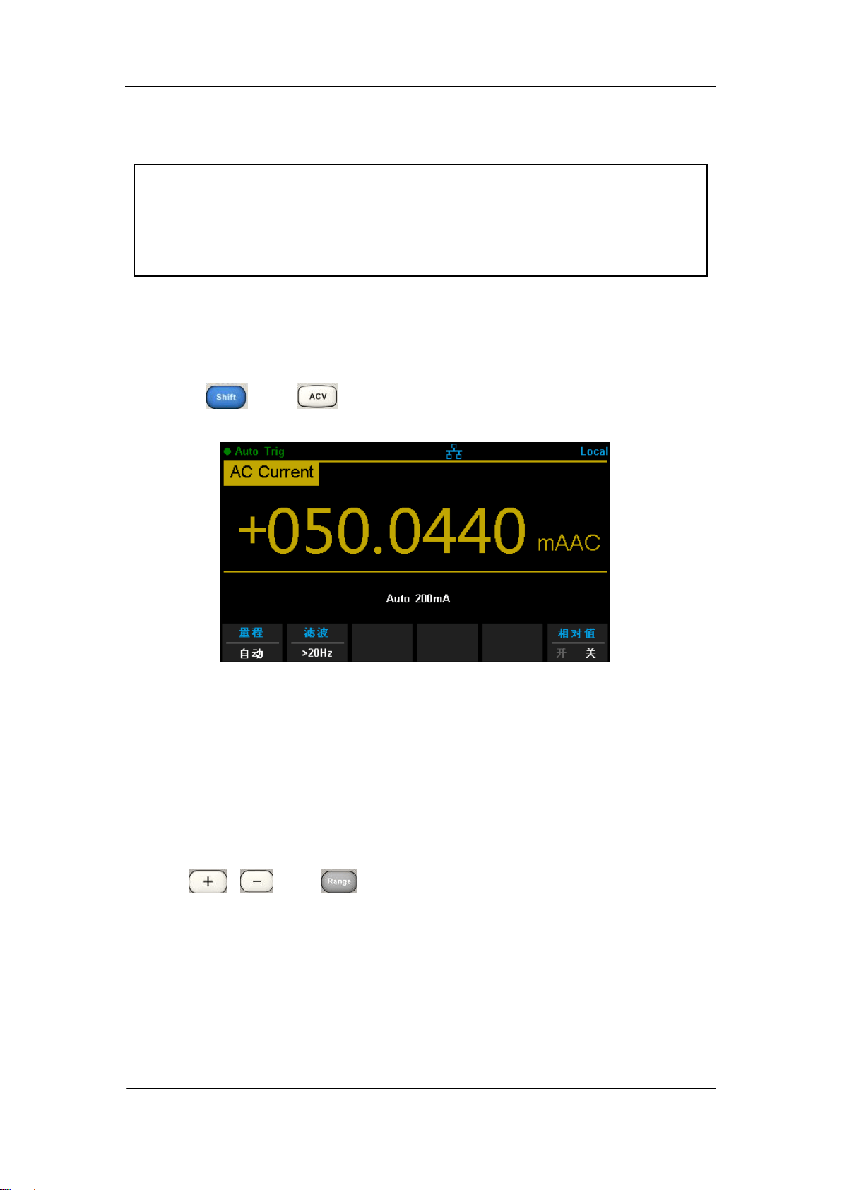
1. Enable the ACI measurement
Press and on the front panel to enter the AC current
measurement interface, as shown in Diagram 2- 12.
Diagram 2- 12 AC Current Measurement Interface
2. Make connection
Connect the test leads with the measured signal by referring to
“Measurement Connections”.
3. Set the range
Press 【Range】to select a range for the measurement. You can also use
the , , and keys on the front panel to select the range.
Auto (autorange) automatically selects the range for the measurement
based on the input. Autoranging is convenient, but it results in slower
measurements than using a manual range. Autoranging goes up a range
at 110% of the present range, and down a range below 10% of the
present range.
4. Set the filter

SIGLENT
36 SDM3065X Digital Multimeter
Press【Filter】and choose the filter for the measurement. The instrument
provides three different AC filters --“>3Hz”, “>20Hz” and “>200Hz”. You
should generally select the highest frequency filter whose frequency is less
than that of the signal you are measuring,
5. Set the relative value (Optional operation)
Press 【Rel】 to open or close Relative math function. When it is opened,
the reading displayed is a value which comes from the result of actual
measurement value subtracts the relative value that has been set. The
default relative value is the measurement value when the function is
opened.(Please refer to “ Math Functions” in Chapter 2 to know about the
details.)
6. Read the measurement value
The multimeter measures the input signal according to the current
measurement settings and displays the measurement result on the
screen.
7. Make math operation (advanced)
You can perform math operation (Statistics, Limit and REL) on every ACI
measurement reading. For details, please refer to “Math Operations”.
8. Display the graph (advanced)
You can analyze the measurement data by using “Bar Meter”, “Trend Char” or
“Histogram display”. For details, please refer to “Display Mode”.
SIGLENT
SDM3065X Digital Multimeter 37
To Measure Resistance
Range: 200Ω, 2kΩ, 20kΩ, 200kΩ, 1MΩ, 10MΩ, 100MΩ
Max Resolution: 100μΩ (in the range of 200Ω)
Input Protection: a 1000 V protection is available in all ranges and a 10%
overrange for all ranges. If the reading exceeds the range, “overload”
will be displayed.
SDM3065X provides 2-wire and 4-wire resistance measurements. When the
measured resistance is lower than 100 kΩ, the 4-wire resistance measurement
is recommended to reduce the measurement error caused by test lead
resistance and contact resistance between the probe and the testing point
because these two resistances cannot be ignored any more, compared to the
measured resistance.
Operating Steps:
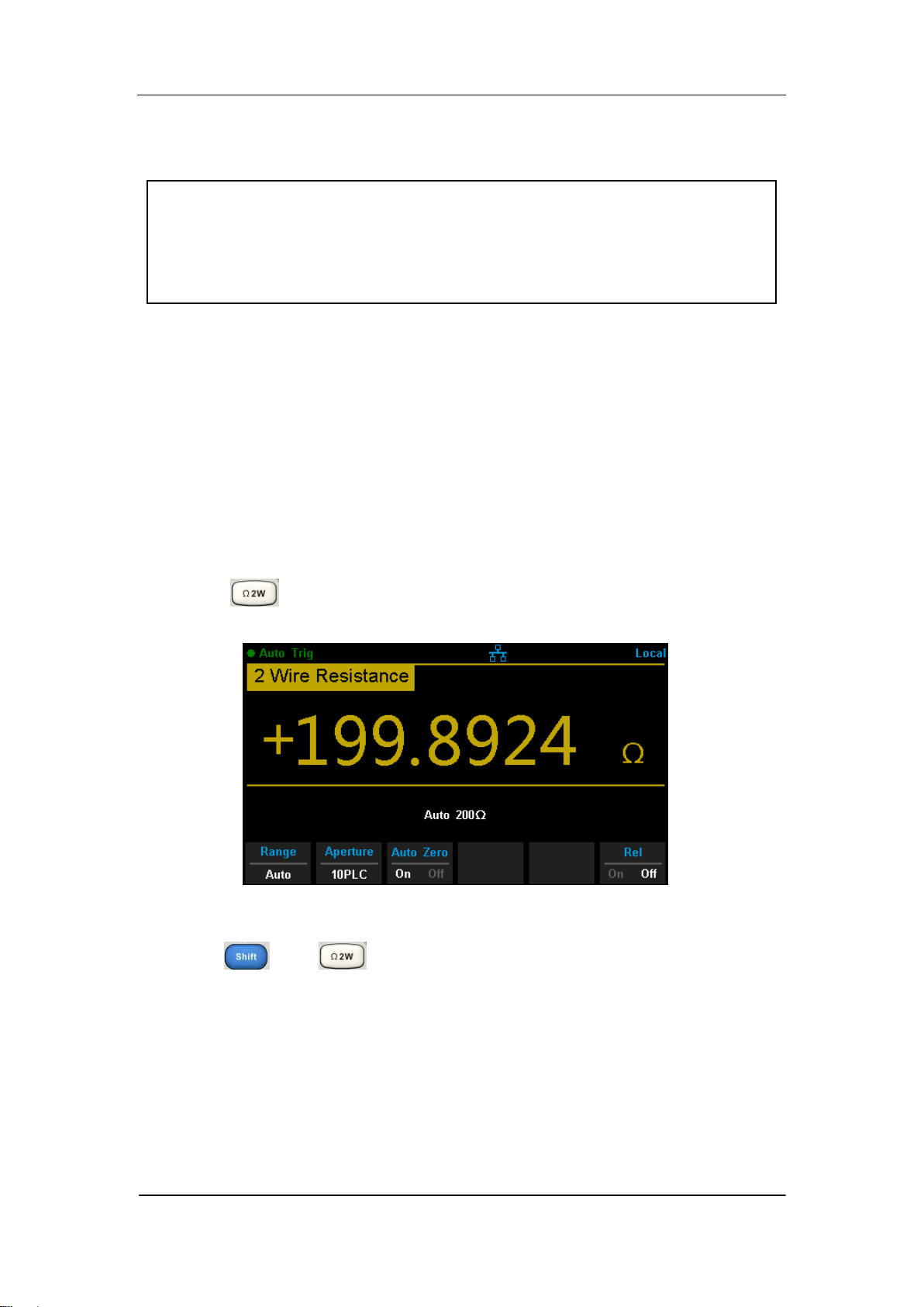
1. Enable 2-wire / 4-wire resistance measurement
Press on the front panel to enter the 2-wire resistance
measurement interface, as shown in Diagram 2- 13.
Diagram 2- 13 2 Wire Resistance Measurement Interface
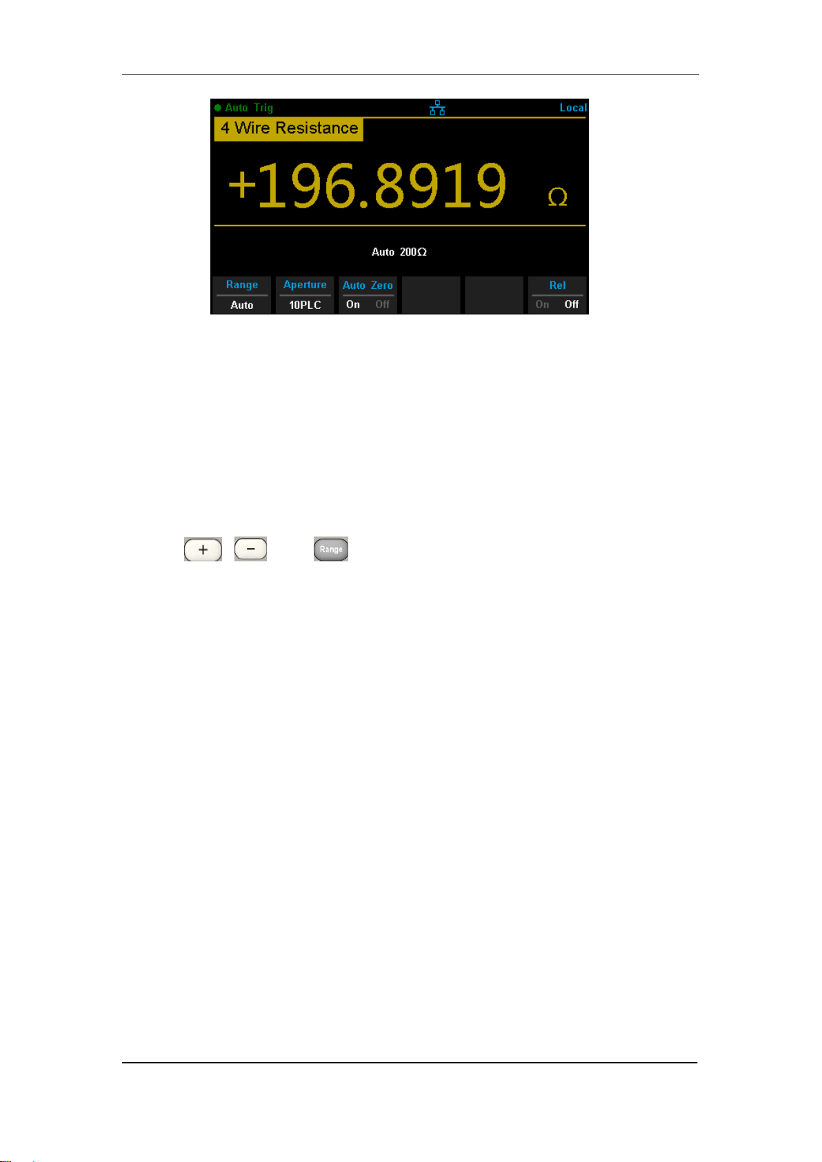
Press and on the front panel to enter the 4-wire resistance
measurement interface, as shown in Diagram 2- 14.
SIGLENT
38 SDM3065X Digital Multimeter
Diagram 2- 14 4 Wire Resistance Measurement Interface
2. Make connection
Connect the test leads with the measured signal by referring to
“Measurement Connections”.
3. Set the range
Press 【Range】to select a range for the measurement. You can also use
the , , and keys on the front panel to select the range.
Auto (autorange) automatically selects the range for the measurement
based on the input. Autoranging is convenient, but it results in slower
measurements than using a manual range. Autoranging goes up a range
at 110% of the present range, and down a range below 10% of the
present range.
4. Set the intergration
Press 【Aperture】and choose the number of power-line cycles (PLCs) to
use for the measurement. Selecting 100 PLC provides the best noise
rejection and resolution, but the slowest measurements
5. Autozero setting
Press 【Auto Zero】to enable or disable this function. Autozero provides the
most accurate measurements, but requires additional time to perform the
zero measurement.With autozero enabled (On), the DMM internally
measures the offset following each measurement. It then subtracts that
measurement from the preceding reading. This prevents offset voltages
present on the DMM‟s input circuitry from affecting measurement accuracy.
6. Set the relative value (Optional operation)
Press 【Rel】 to open or close Relative math function. When it is opened,

SIGLENT
SDM3065X Digital Multimeter 39
the reading displayed is a value which comes from the result of actual
measurement value subtracts the relative value that has been set. The
default relative value is the measurement value when the function is
opened.(Please refer to “ Math Functions” in Chapter 2 to know about the
details.)
7. Read the measurement value
The multimeter measures the input signal according to the current
measurement settings and displays the measurement result on the
screen.
8. Make math operation (advanced)
You can perform math operation (Statistics, Limit and REL) on every
resistance measurement reading. For details, please refer to “Math
Operations”.
9. Display the graph (advanced)
You can analyze the measurement data by using “Bar Meter”, “Trend
Char” or “Histogram display”. For details, please refer to “Display Mode”.

SIGLENT
40 SDM3065X Digital Multimeter
To Measure Capacitance
Range: 2nF, 20nF, 200nF, 2μF, 20μF, 200μF, 2mF, 20mF, 100mF
Max Resolution: 1pF (in the range of 2nF)
Input Protection: a 1000 V protection is available in all ranges. If the
reading exceeds the range, “overload” will be displayed.
Operating Steps:
1. Enable the Capacitance measurement
Press on the front panel to enter the Capacitance measurement
interface, as shown in Diagram 2- 15.
Diagram 2- 15 Capacitance Measurement Interface
2. Make connection
Connect the test leads with the measured signal by referring to
“Measurement Connections”.
3. Set the range
Press 【Range】to select a range for the measurement. You can also use
the , , and keys on the front panel to select the range.
Auto (autorange) automatically selects the range for the measurement
based on the input. Autoranging is convenient, but it results in slower
measurements than using a manual range. Autoranging goes up a range
at 110% of the present range, and down a range below 10% of the
present range.
4. Set the relative value (Optional operation)
Press 【Rel】 to open or close Relative math function. When it is opened,

SIGLENT
SDM3065X Digital Multimeter 41
the reading displayed is a value which comes from the result of actual
measurement value subtracts the relative value that has been set. The
default relative value is the measurement value when the function is
opened.(Please refer to “ Math Functions” in Chapter 2 to know about the
details.)
5. Read the measurement value
The multimeter measures the input signal according to the current
measurement settings and displays the measurement result on the
screen.
6. Make math operation (advanced)
You can perform math operation (Statistics, Limit and REL) on every ACI
measurement reading. For details, please refer to “Math Operations”.
7. Display the graph (advanced)
You can analyze the measurement data by using “Bar Meter”, “Trend Char”
or “Histogram display”. For details, please refer to “Display Mode”.
NOTE:
Please short contact the two feet of an electrolytic capacitor by using a test
lead before measuring the electrolytic capacitor.
SIGLENT
42 SDM3065X Digital Multimeter
To Measure Frequency or Period
Frequency (Period) Range: From 3 Hz to 1MHz (from 0.33s to 1μs)
Input Signal Range: 200mV, 2V, 20V, 200V, 750V
Input Protection: a 750 V protection is available in all ranges.
Operating Steps:
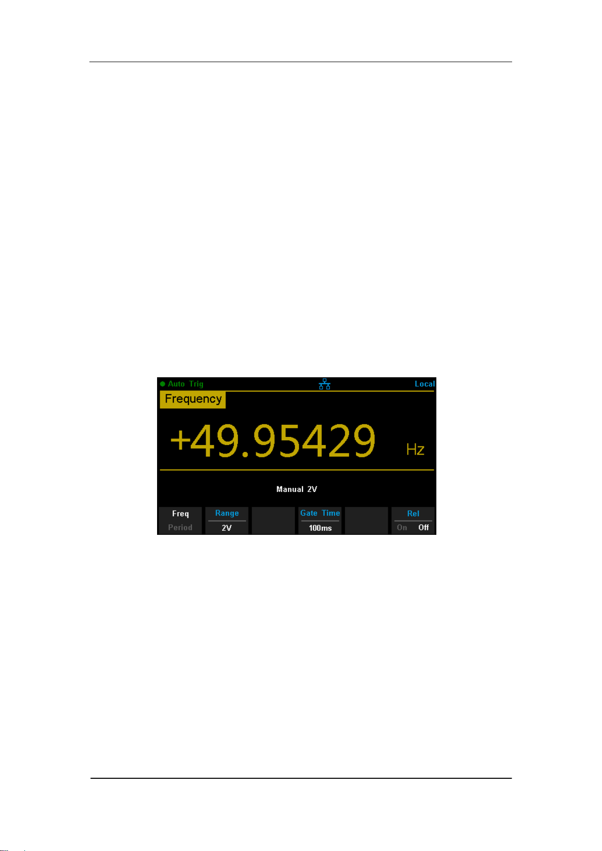
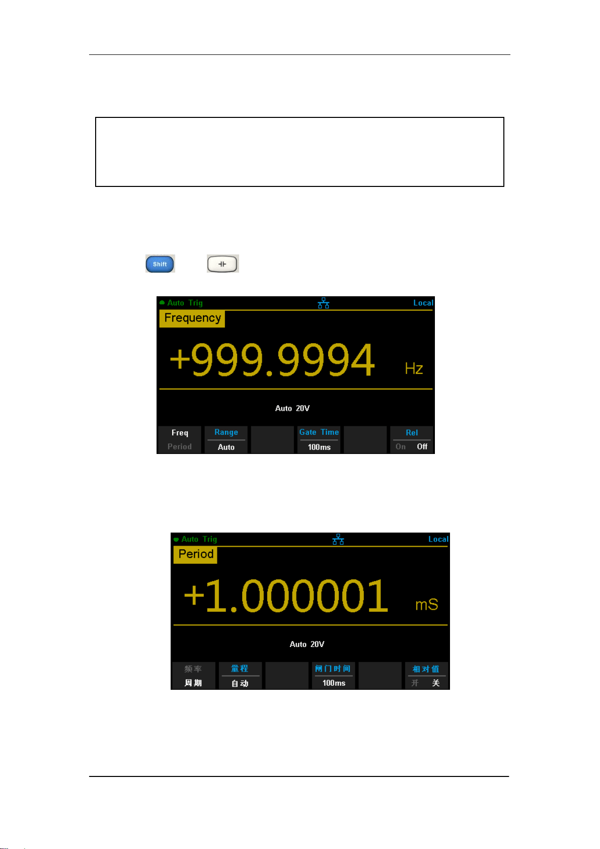
1. Enable the Freq/Period measurement
Press and on the front panel, then select 【Freq】 to enter
the frequency measurement interface, as shown in Diagram 2- 16.
Diagram 2- 16 Fequency Measurement Interface
Select 【Period】to enter the period measurement interface, as shown in
Diagram
Diagram 2- 17 Period Measurement Interface
2. Make connection
Connect the test leads with the measured signal by referring to
“Measurement Connections”.

SIGLENT
SDM3065X Digital Multimeter 43
3. Set the range
Press 【Range】to select a range for the measurement. You can also use
the , , and keys on the front panel to select the range.
Auto (autorange) automatically selects the range for the measurement
based on the input. Autoranging is convenient, but it results in slower
measurements than using a manual range. Autoranging goes up a range
at 110% of the present range, and down a range below 10% of the
present range.
4. Set the gate time
Press 【Gate Time】and choose the measurement aperture of 1 ms , 10 ms,
100 ms (default), or 1 s.
5. Set the relative value (Optional operation)
Press 【Rel】 to open or close Relative math function. When it is opened,
the reading displayed is a value which comes from the result of actual
measurement value subtracts the relative value that has been set. The
default relative value is the measurement value when the function is
opened.(Please refer to “ Math Functions” in Chapter 2 to know about the
details.)
6. Read the measurement value
The multimeter measures the input signal according to the current
measurement settings and displays the measurement result on the
screen.
7. Make math operation (advanced)
You can perform math operation (Statistics, Limit and REL) on every
measurement reading. For details, please refer to “Math Operations”.
8. Display the graph (advanced)
You can analyze the measurement data by using “Bar Meter”, “Trend Char”
or “Histogram display”. For details, please refer to “Display Mode”.
SIGLENT
44 SDM3065X Digital Multimeter
To Test Continuity
Test Current Source: 1mA
Max Resolution: 0.01Ω
Input Protection: 1000V Input Protection
Open-circuit Voltage: <8V
Beep Threshold (short-circuit resistance):from 0Ω to 2000Ω
This function measures the resistance of the circuit with about 1mA curren
source. When the measured resistance is lower than the short-circuit
resistance (Threshold), the beeper sounds(if the Beeper is on). Otherwise,
“open” is displayed on the screen
Operating Steps:
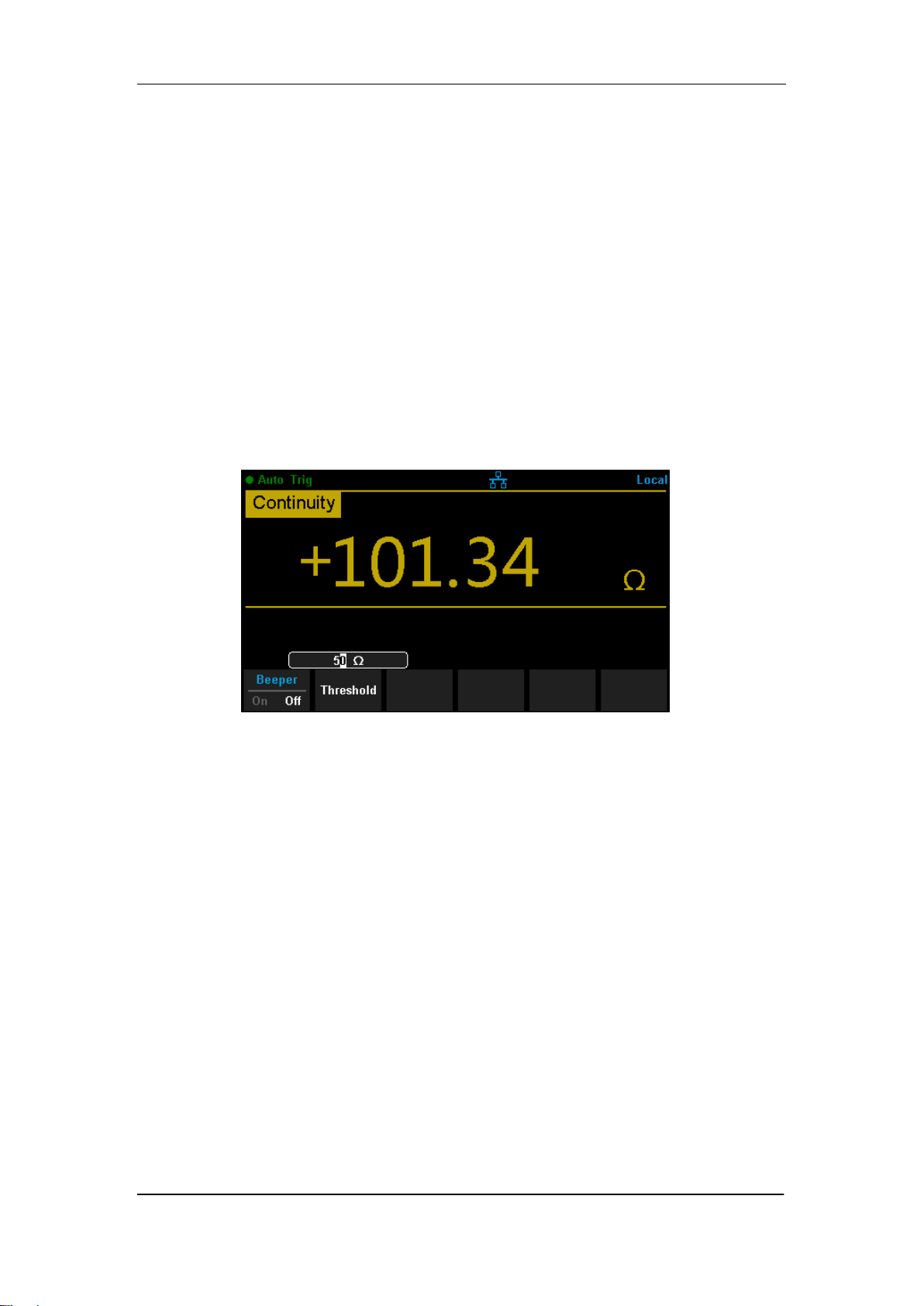
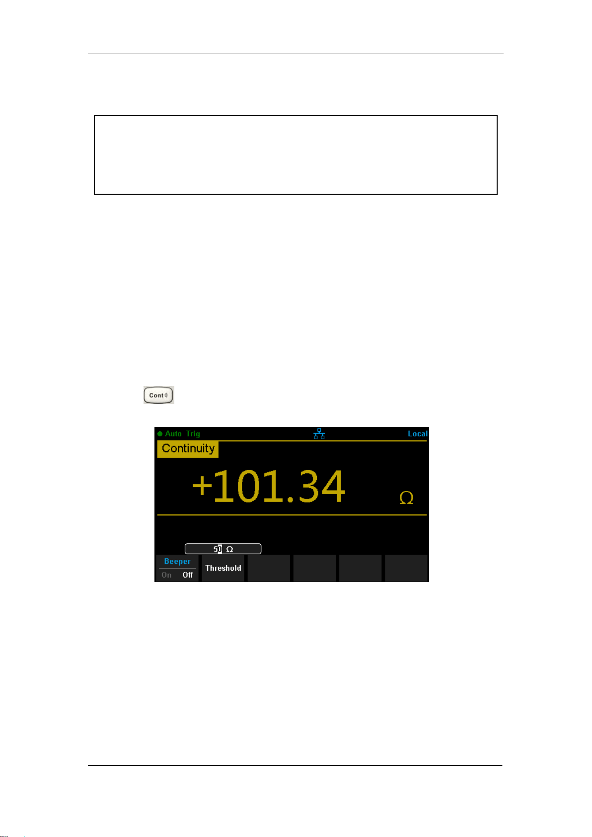
1. Enable the Cont measurement
Press on the front panel to enter the Continuity test interface, as
shown in Diagram 2- 18.
Diagram 2- 18 Continuity Measurement Interface
2. Make connection
Connect the test leads with the measured signal by referring to
“Measurement Connections”.
3. Set the short-circuit resistance (Threshold)
Enter a desired value using the direction keys. The range is from 0 Ω to
2000 Ω and the default is 50 Ω.

SIGLENT
SDM3065X Digital Multimeter 45
4. Read the measurement value
The multimeter measures the input signal according to the current
measurement settings and displays the measurement result on the screen.
5. Make math operation (advanced)
You can perform math operation (Statistics, Limit) on every measurement
reading. For details, please refer to “Math Operations”.
6. Display the graph (advanced)
You can analyze the measurement data by using “Bar Meter”, “Trend Char”
or “Histogram display”. For details, please refer to “Display Mode”.
NOTE:
Before testing continuity, please cut off the power and discharge all the
high-voltage containers to avoid damages to the Multimeter.
SIGLENT
46 SDM3065X Digital Multimeter
To Test Diode
Test Current Source:1mA
Voltage Measurement Range:0V~4V
Max Resolution:10μV
Input Protection: 1000V Input Protection
Open-circuit Voltage:<8V
This function measures the forward voltage drop on the diode. When the
voltage is lower than Threshold, the beeper sounds (if the beeper is on).
Operating Steps:
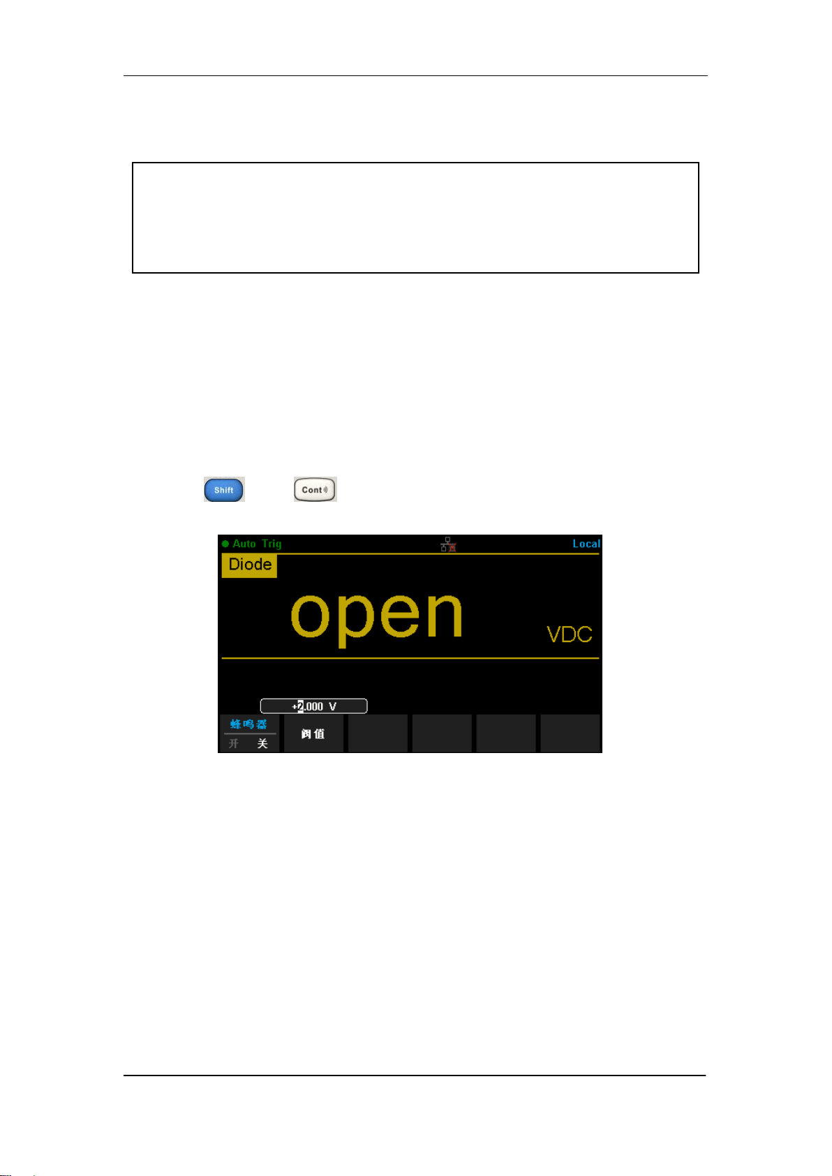
1. Enable the Diode measurement
Press and on the front panel to enter the Diode test
interface, as shown in Diagram 2- 19.
Diagram 2- 19 Diode Measurement Interface
2. Make connection
Connect the test leads with the measured signal by referring to
“Measurement Connections”.
3. Set the Threshold
Enter a desired value using the direction keys. The range is from 0 to 4V
and the default is 2V.
4. Read the measurement value
The multimeter measures the input signal according to the current
measurement settings and displays the measurement result on the screen. If

SIGLENT
SDM3065X Digital Multimeter 47
the reading exceeds the threshold, “open” will be displayed.
5. Evaluate the results of measurement
Reverse the probes and measure the forward voltage drop on the diode
again. Evaluate the diode according to the following rules:
If the Multimeter displays “open” when in reverse bias model, it
indicates that the diode is normal.
If the Multimeter shows voltage about 0V and the instrument beeps
persistently when in forward and reverse bias model, it indicates that the
diode is short.
If the Multimeter shows “open” when in forward and reverse model, it
indicates that the diode is open.
6. Make math operation (advanced)
You can perform math operation (Statistics, Limit) on every measurement
reading. For details, please refer to “Math Operations”.
7. Display the graph (advanced)
You can analyze the measurement data by using “Bar Meter”, “Trend Char”
or “Histogram display”. For details, please refer to “Display Mode”.
Note:
Before testing diode, please cut off the power and discharge all the
high-voltage containers to avoid damages to the Multimeter.
SIGLENT
48 SDM3065X Digital Multimeter
To Measure Temperature
SDM3065X can directly measure the temperature using TC (Thermocouple)
and THERM (Thermistor) sensors.
Operating Steps:
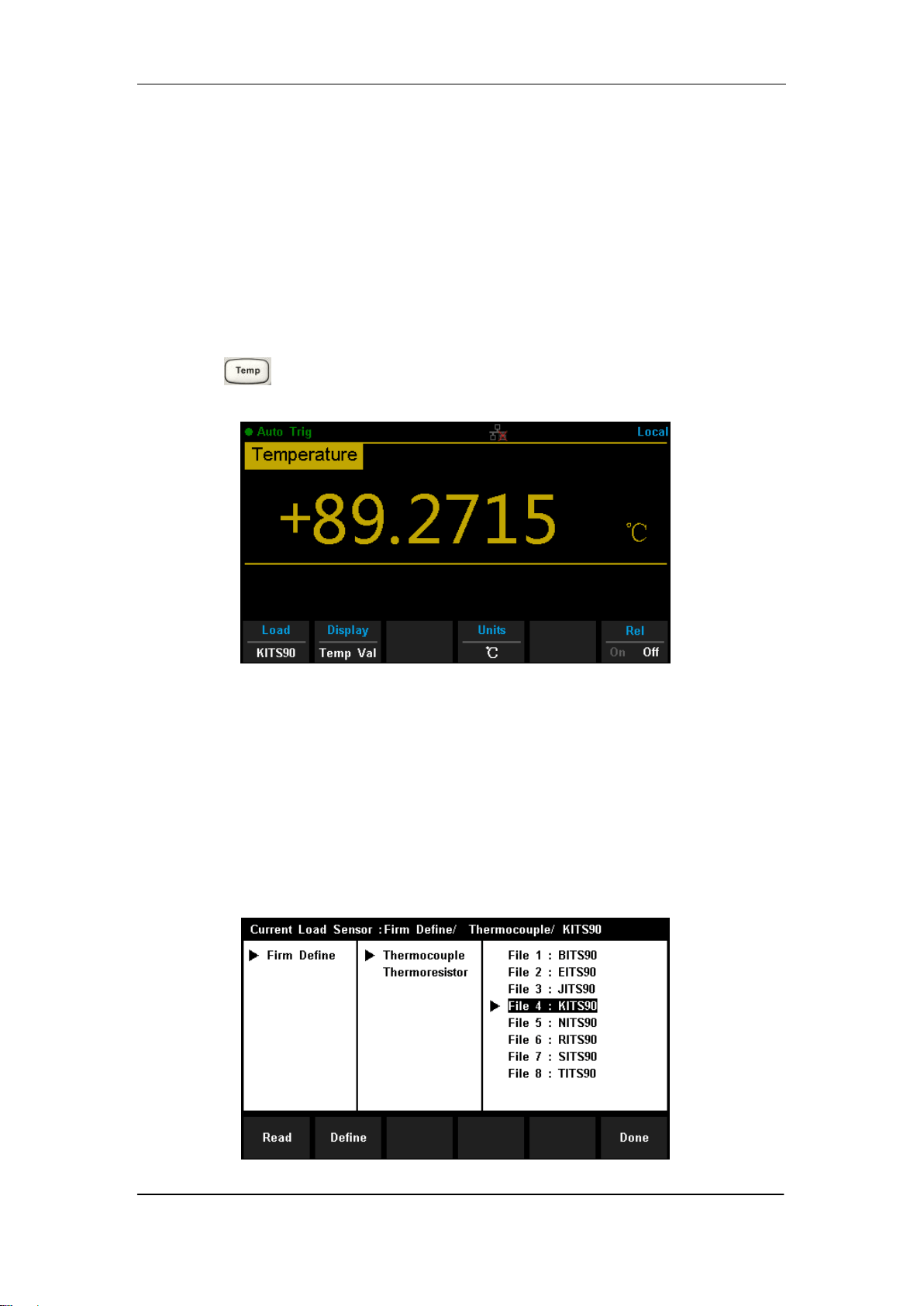
1. Enable the Diode measurement
Press on the front panel to enter the Temperature measurement
interface, as shown in Diagram 2- 20.
Diagram 2- 20 Temperature Measurement Interface
2. Make connection
Connect the test leads with the measured signal by referring to
“Measurement Connections”.
3. Set the type of sensor
Press 【Load】and use direction keys to choose a desired temperature
sensor. Press 【Define】to view the configurations .Then press 【Read】
to apply the current temperature sensor configurations.
Diagram 2- 21 Load a Configuration File
SIGLENT
SDM3065X Digital Multimeter 49
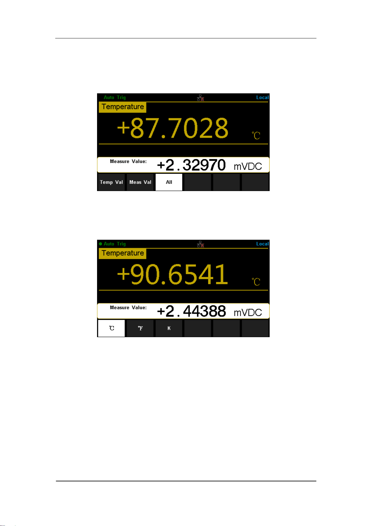
4. Set the display mode
Press 【Display】to choose the display mode. The Multimeter supports
three display modes: Temperature Value, Measured Value and All
(Temperature Value and Measured Value will be shown on the display
together).
Diagram 2- 22 Choose Display Mode of Temperature Measurement
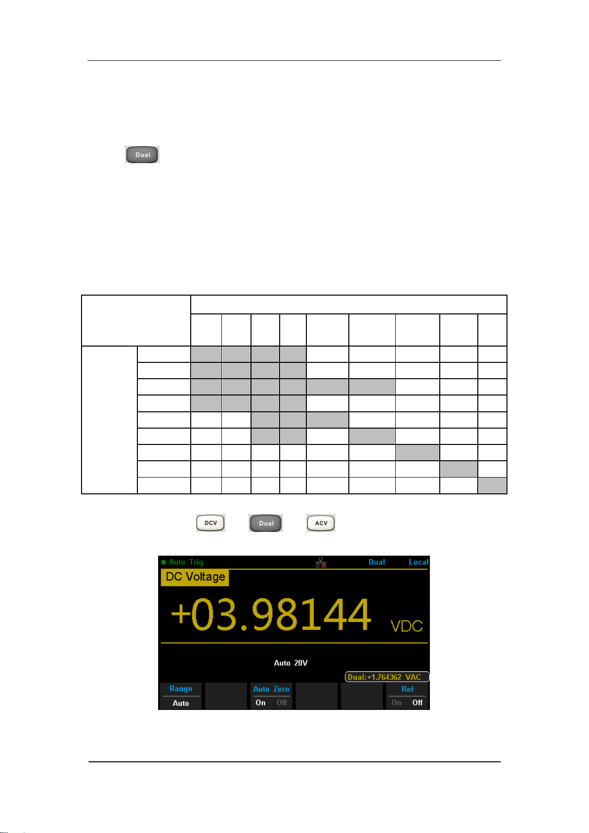
5. Set the unit of temperture
Press 【Units】to choose the unit of temperature. The Multimeter supports
three units: °C ,°F , K.
Diagram 2- 23 Unit Selection Interface
6. Set the relative value (Optional operation)
Press 【Rel】 to open or close Relative math function. When it is opened,
the reading displayed is a value which comes from the result of actual
measurement value subtracts the relative value that has been set. The
default relative value is the measurement value when the function is
opened.(Please refer to “ Math Functions” in Chapter 2 to know about the
details.)
7. Read the measurement value
The multimeter measures the input signal according to the current
measurement settings and displays the measurement result on the

SIGLENT
50 SDM3065X Digital Multimeter
screen.
8. Make math operation (advanced)
You can perform math operation (Statistics, Limit and REL) on every
measurement reading. For details, please refer to “Math Operations”.
9. Display the graph (advanced)
You can analyze the measurement data by using “Bar Meter”, “Trend Char”
or “Histogram display”. For details, please refer to “Display Mode”.
SIGLENT
SDM3065X Digital Multimeter 51
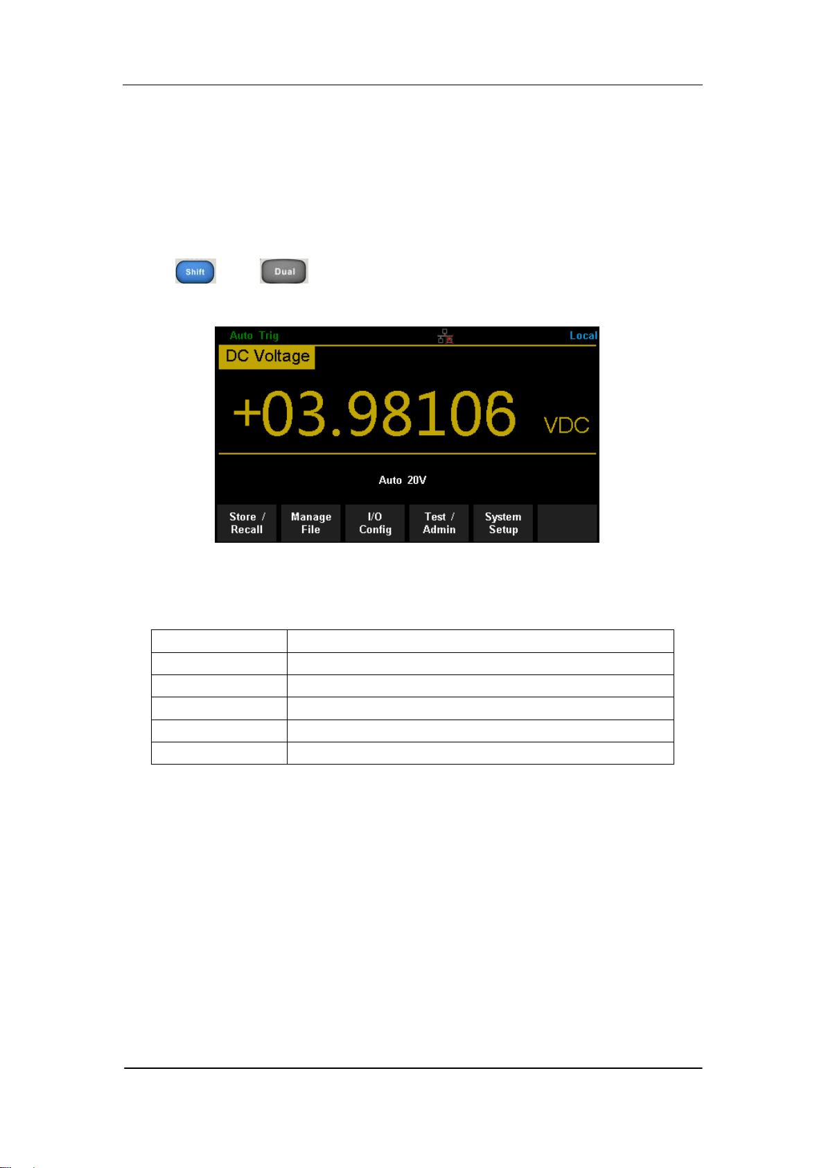
Dual-display Function
Dual-display function is used to improve test and measurement functions.
Press to open Dual-display function and the upper right corner will
show “Dual”. By this time, press a function key if this function can be used as
the vice display, it will be displayed in the Vice Display. The Main Display will
display the function that is selected before the Dual-display function is turned
on. All the available combinations are listed in table 2-3.
Table 2- 3 Available Main/Vice Function Combinations (shade is available)
Main Display Function
DCV
DCI
ACV
ACI
FREQ
PERIOD
2-Wire
R
4-Wire
R
Cap
Vice
Display
Function
DCV
DCI
ACV
ACI
FREQ
PERIOD
2-Wire R
4-Wire R
Cap
For example, press → → to enter the follwing interface
Diagram 2- 23 Dual-display Interface

SIGLENT
52 SDM3065X Digital Multimeter
Instruction:
1. If the same measurement function is used in both Main and Vice Display.
The readings in both of the display will update at the same time.
If math function (dBm, dB) is used in Main Display, when opening Vice
Display, math operation will be closed automatically and Vice Display will
show the same measurement result as Main Display.
If math function (Statistics, Limits, Relative) is used in Main Display, when
opening Vice Display, the result will still be shown in Main Display and
Vice Display will show the same measurement result as Main Display.
2. If different measurement functions are used in both Main and Vice Display.
The readings in both of the display will update alternately.
If math function (dBm, dB) is used in Main Display, when opening Vice
Display, math operation will be closed automatically and Vice Display will
show the second selected function normally.
If math function (Statistics, Limits, Relative) is used in Main Display, when
opening Vice Display, the result will still be shown in Main Display and
Vice Display will show the second selected function normally.
3. If Temperature function is used in Main Display, set the display mode
( →【Display】→【All】). Then the result will be shown in Main
Display and the current measurement value is shown in Vice Display.
4. Auto Range is adopted by Vice Display. If the same measurement function
is used in both the display, so does the range.
5. Measured data in Vice Display cannot be saved into “History”.
SIGLENT
SDM3065X Digital Multimeter 53
Utility Function
The Utility function enables users to set up system parameters, interface
parameters of the multimeters.
Press and to enter the operating menu of Utility function, as
the following diagram shows.
Diagram 2- 24 Utility Function Configuration Interface
Table 2- 1 Utility Function Menu Description
Function Menu
Description
Store/Recall
Store or recall state files.
Manage File
Create a new file, copy, rename or delete a file.
I/O Config
Configure LAN and GPIB interface.
Test/Admin
Provide board test function.
System Setup
Configure instrument‟s user settings.

SIGLENT
54 SDM3065X Digital Multimeter
Store and Recall
The Store/Recall function enables users to store and recall the instrument
state and data files in the local storage as well as in USB storage. After
entering into the function menu of Utility, press 【Store/Recall】to enter the
interface as shown in diagram 2-25.
Diagram 2- 25 Store and Recall Interface
Table 2- 2 Store/Recall Function Menu Description
Function Menu
Description
Store Settings
Store state or data files.
Recall Settings
Recall state files.
Power On
Select the state that is loaded at power-up.
Security Ercase
Delete all the files stored in local storage and
restore the instrument to factory default state.
Set to Defaults
Restore the instrument to factory default state.
Done
Return to the higher level menu.
Store Settings
Store settings allows you to save the system configuration (in the form
of .xml ) or measurement data (in the form of .csv ) into the internal memory
or an external USB storage device. After entering into the function menu of
Store/Recall , press【Store Settings】to enter the following interface.
SIGLENT
SDM3065X Digital Multimeter 55
Diagram 2- 26 Store Settings Interface
Table 2- 3 Storage Function Menu Description
Function
Menu
Settings
Description
Browse
Choose the location that file will be saved.
File Name
Input the file name.
Type
.xml / .csv
Choose the type of file that will be saved.
Store Data
Store the specified file.
Done
Return to the higher level menu.
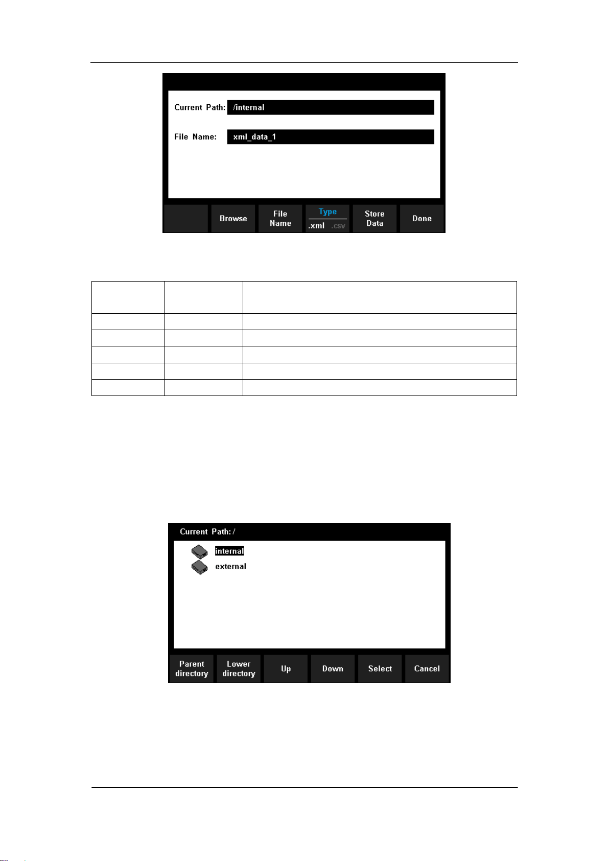
Operating Steps:
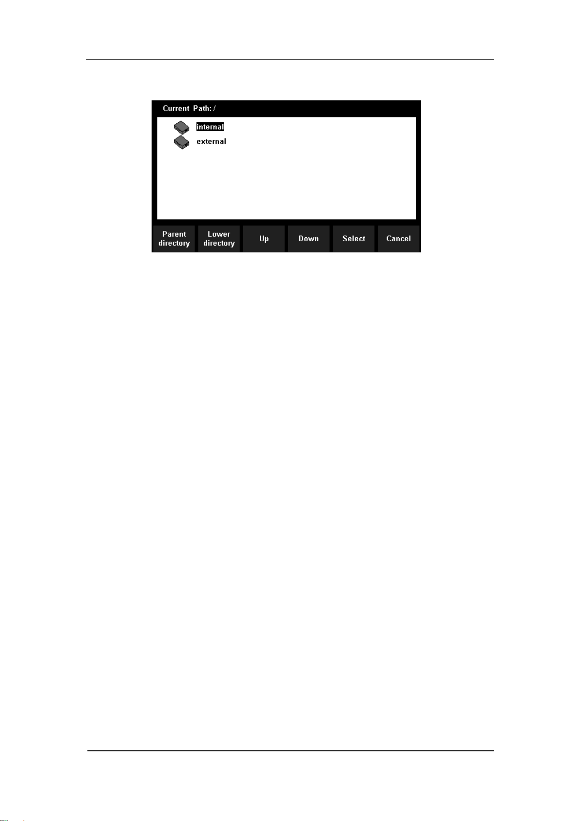
1. Set the storage directoty
Press 【Browse】to enter the following interface, then use direction keys
or menu operation keys to choose the storage directory. Press 【Select】
to set the current directory as storage location and Return to higher level
menu.
Diagram 2- 27 storage directory Settings Interface
2. Set the file name
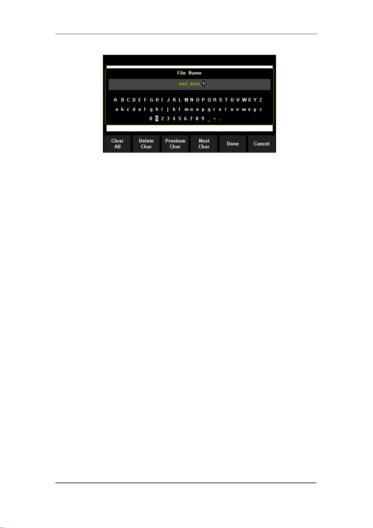
Press 【File Name】to enter the following interface and input the name of
the stored file.
SIGLENT
56 SDM3065X Digital Multimeter
Diagram 2- 28 Input Fire name
The method of inputting file name:
Press direction keys to select a desired char in the input area.
Press “OK” key on the front panel to input selected char in the input
area.
Press【Clear All】to clear all input chars.
Press【Delete Char】to delete the letter on which the cursor taking
place.
Press【Previous Char】to move the cursor in the file name area to the
previous char.
Press【Next Char】to move the cursor in the file name area to the next
char.
Press【Done】to save the current file and return to the higher level
menu.
Press【Cancel】to cancel the current operation and return to the
higher level menu.
.
3. Set the type of stored file
Press 【Type】to set the type of stored file.
.xml: save the current system configuration as an “.xml” file.
.csv: save the current measurement result as a “.csv” file.
4. Save the file
Press 【Store Data】 to store the specified file
5. Exit
Press 【Done】to return to the higher level menu.
Recall Settings
Recall settings allows you to read the system configuration from the internal
memory or an external USB storage device. After entering into the function
SIGLENT
SDM3065X Digital Multimeter 57
menu of Store/Recall , press【Recall Settings】to enter the following interface.
Diagram 2- 29 Recall Settings Interface
Use direction keys or menu operation keys to choose the state file with the
suffix “.xml”. Press【Select】to read the file and retore the instrument to
specified state. Press 【Cancel】to return to higher level menu.
Power On
Select a system configuration to be used at power-on from “Default” and
“Last” (configuration at last power-off). The setting will be available at the
next power-on.
Security Erase
Press 【Security Erase】, the instrument will display prompt message „Are you
sure to delete all stored files?‟ Then press 【Yes】, the instrument will delete all
the files stored in local storage and restore the instrument to factory default
state.
Set to Defaults
Press 【Set to Defaults】the instrument will be restored to factory default state
SIGLENT
58 SDM3065X Digital Multimeter
Manage File
The Manage Files function allows you to create, copy, delete, and rename
files and folders in the instrument's internal flash memory or on a USB drive
attached to the front panel. It also allows you to capture the current screen to a
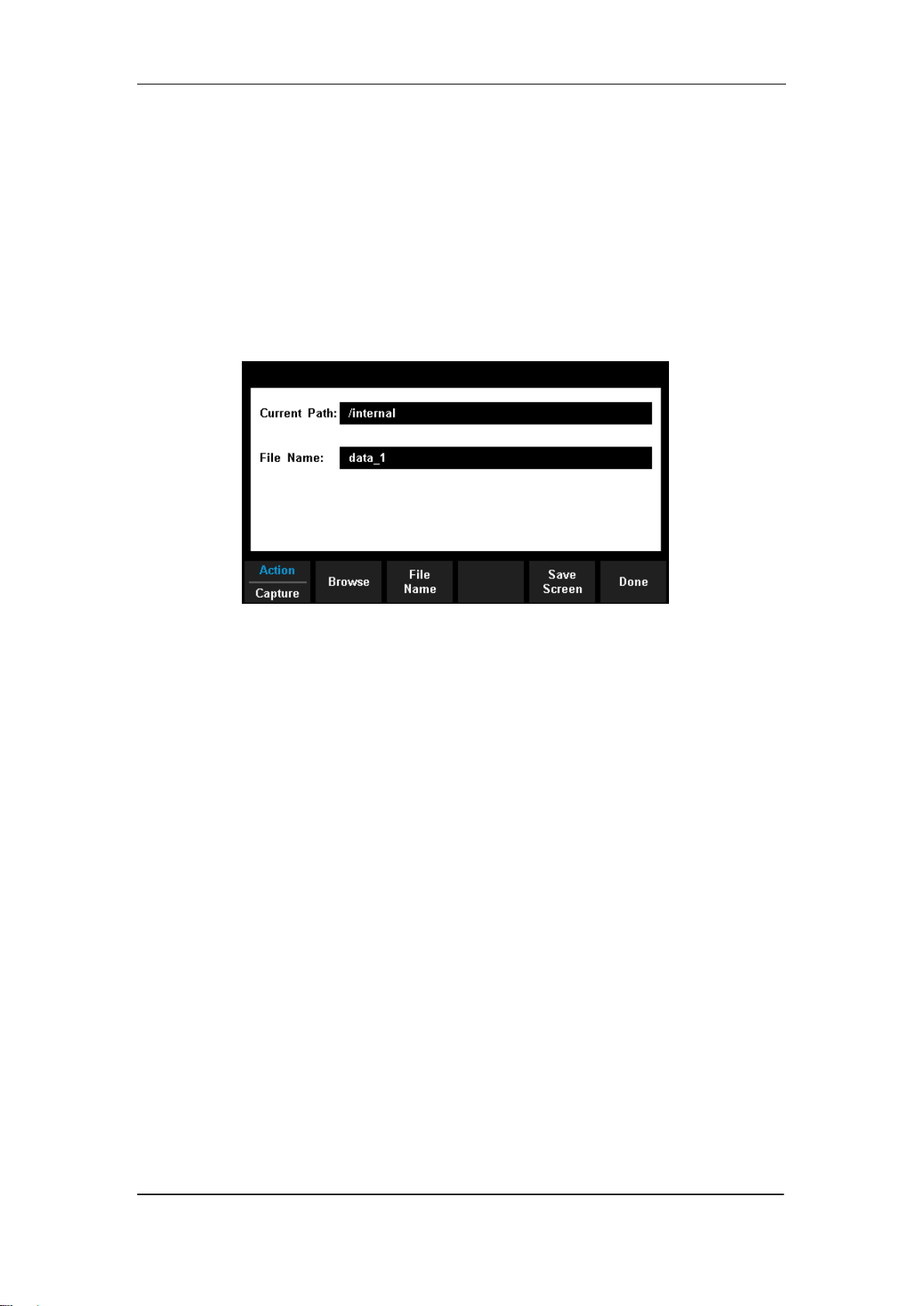
bitmap (*.bmp) file. After entering into the function menu of Utility, press
【Manage File】to enter the interface as shown in diagram 2-30.
Diagram 2- 30 Manage File Interface
Press 【Action】and select 【Folder】, 【Capture Display】, 【Copy】,
【Rename】or【Delete】to do the corresponding operation.
Folder - To create a folder, Browse to the internal or external location for
the folder, press File Name, enter a folder name and press Done. Press
Create Folder > Done.
Capture Display- To saves a screen capture, Browse to the internal or
external location for the screen capture, press File Name, enter a name
and press Done. Press Save Screen > Done.
Copy - To copy a file or folder, press Copy. Browse to the folder or file to
be copied and press Select. Press Copy Path and select an internal or
external path for copying. Press Perform Copy > Done.
Rename - To rename a file or folder, press Rename. Browse to the
folder or file to be renamed and press Select. Press New Name, enter a
new name and press Done. Press Perform Rename > Done.
Delete - To delete a file or folder, press Delete and Browse to the folder
or file to delete. Press Select >Perform Delete > Done.
SIGLENT
SDM3065X Digital Multimeter 59
I/O Configuration
Press【I/O Config】to enter the following interface and set up the parameters.
Diagram 2- 31 I/O Configuration Interface
LAN Settings
The Multimeter enables users to operate instrument remotely by LAN
interface and store or recall internet settings. You can look over current LAN
settings and set up IP address and subnet mask.
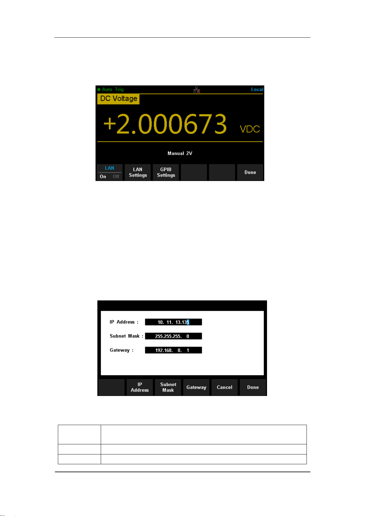
After entering into the function menu of Utility, press 【I/O Config】. Select【On】
→【LAN Settings】→【Modify Settings】to enter the following interface.
Diagram 2- 32 LAN Settings Interface
Table 2- 4 LAN Settings
Function
Menu
Description
IP Address
Set up IP address.
Subnet
Set up subnet mask.
SIGLENT
60 SDM3065X Digital Multimeter
Mask
Gateway
Set up gateway
Cancel
Cancel current operation and return to the higher level menu.
Done
Save all changes and return to the higher level menu.
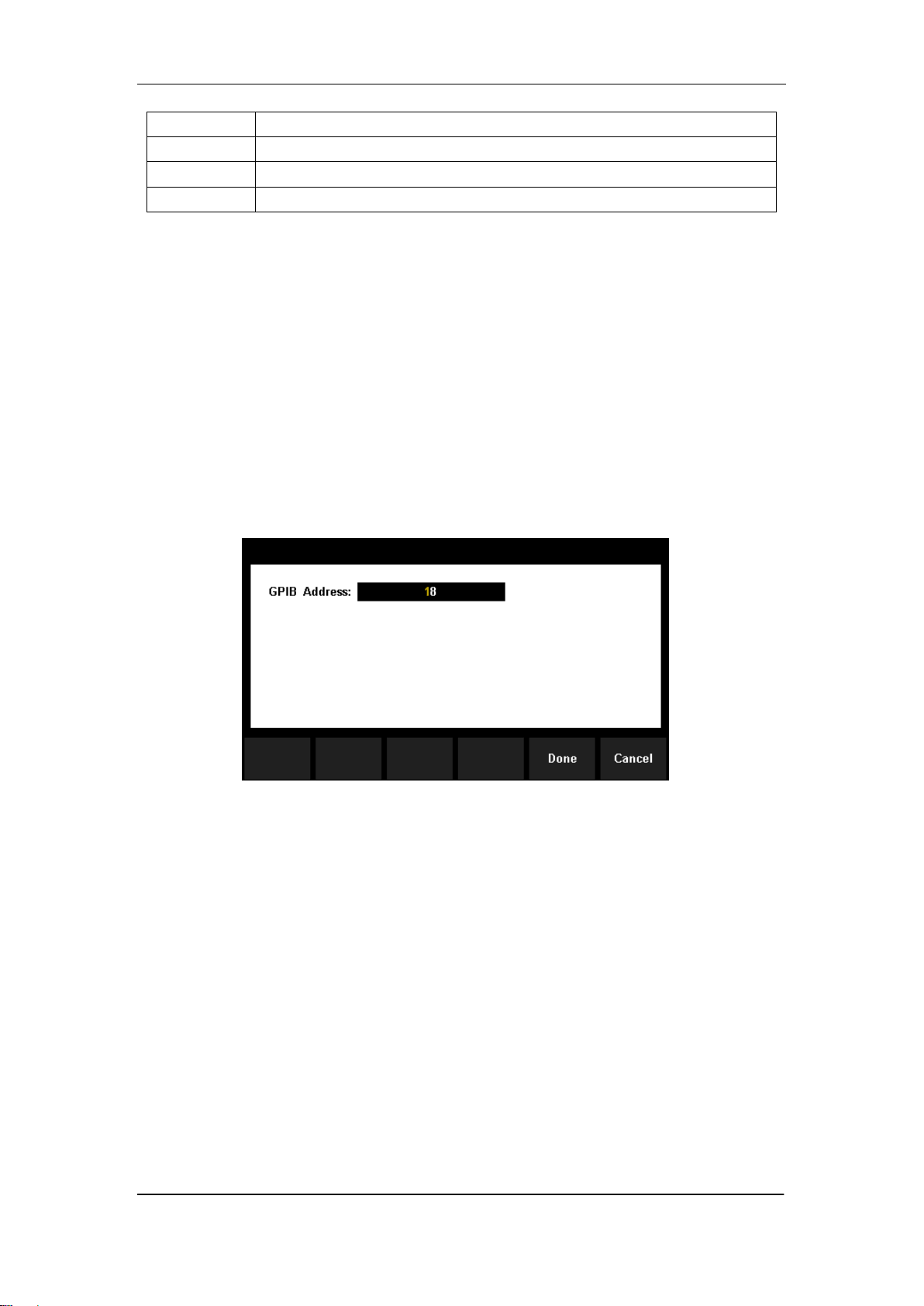
GPIB Settings
Each device on the GPIB (IEEE–488) interface must have a unique address.
The default address is 30 when the instrument is leaving the factory. The
address of Multimeter can be any integral value between 1 and 30.
Operating Steps:
1. After entering into the function menu of I/O configuration, press
【GPIB Settings】to enter the interface shown in diagram 2-33.
Diagram 2- 33 GPIB Settings
2. Users can change the value of GPIB address by direction keys.
3. Press【Select】to set the input value as GPIB address and return to the
higher level menu.
SIGLENT
SDM3065X Digital Multimeter 61
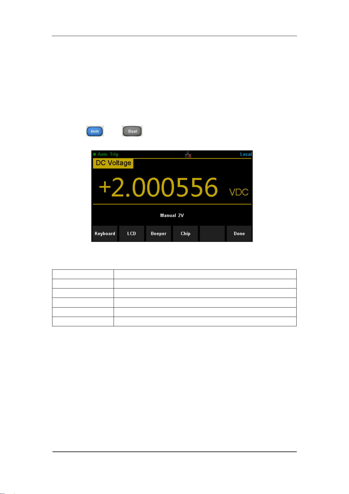
Board Test
SDM3065X provides self-test functions, including Key Test, LCD Test,
Beeper Test and Chip Test.
Operating Steps:
1. Press and , then choose【Test/Admin】→【Board Test】
to enter the following interface.
Diagram 2- 34 Board Test Interface
Table 2- 5 Board Test Function Description
Function Menu
Description
Key
Test the instrument‟s keys.
LCD
Test the instrument‟s LCD screen.
Beeper
Test the instrument‟s beeper.
Chip
Test the instrument‟s chips.
Done
Return the higher level menu.
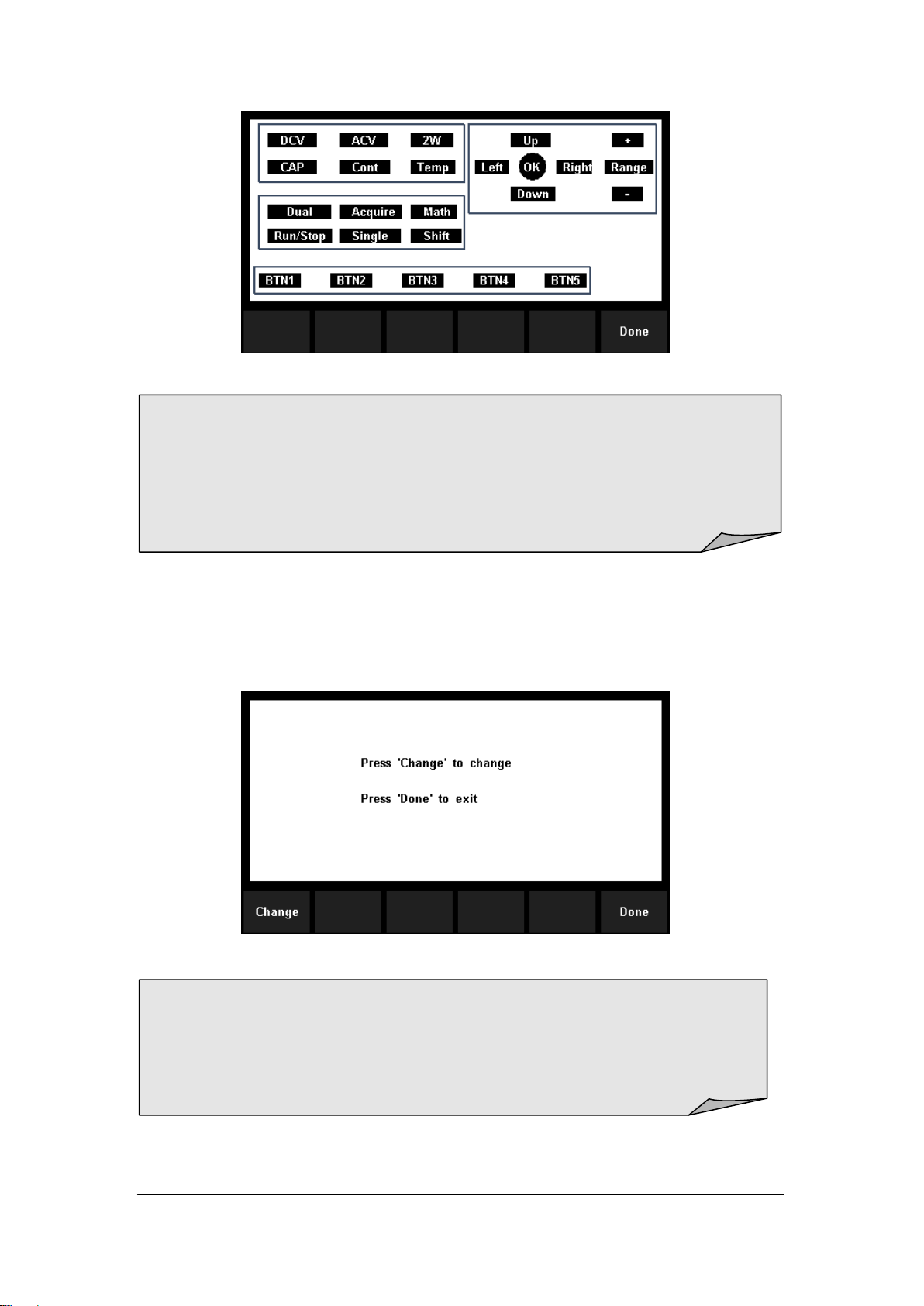
2. Test the keys.
Select【Key】to enter the key test interface, as the Diagram 2-47 shows. The
on-screen lathy rectangle shapes represent the keys on the front panel. Test
all keys and knobs and you should also verify that all the backlit buttons
illuminate correctly.
SIGLENT
62 SDM3065X Digital Multimeter
Diagram 2- 35 Key Test Interface
3. Test the LCD screen.
Select【LCD】to enter the screen test interface, the screen shows the
message:” Press „Change‟ to change Press „Done‟ to exit“. Press【Change】
to start the test and observe if the screen has severe color or other display
error. As the Diagram 2-36 shows.
Diagram 2- 36 LCD Test Interface
4. Test the beeper.
Press 【Beeper】to test the beeper. Under regular circumstance, press
NOTE:
Before you operate, the shapes on the screen display blue color.
The corresponding area of tested buttons or knobs would display green
color.
Press【Done】to exit the test.
NOTE:
Press【Change】to change the color of the screen. There are three
colors: red, blue and green.
Press【Done】to exit the test.
SIGLENT
SDM3065X Digital Multimeter 63
【Beeper】 one time and the instrument will beep one time.
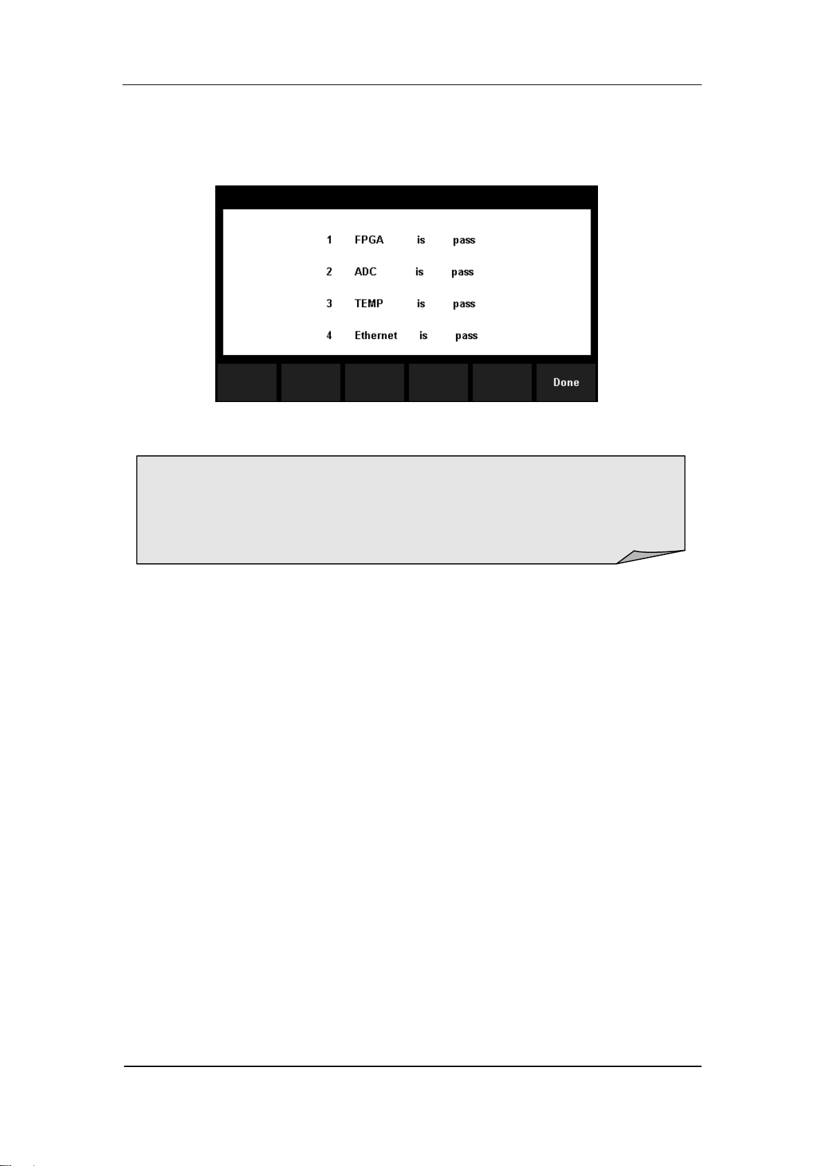
5. Test the chips.
Press【Chip】→【Start】to enter chip test interface, as Diagram 2-37 shows.
Diagram 2- 37 Chip Test Interface
6. Press【Done】to exit the board test.
NOTE:
If the test is passed, the corresponding result shows “pass”.
If the test is failed, the corresponding result shows “fail”.
SIGLENT
64 SDM3065X Digital Multimeter
Firmware Update
The software of the Multimeter can be updated directly via USB flash drive,
updating current software version to desired software version.
Operating Steps:
1. Copy the update file to the USB flash drive.
2. Insert USB flash drive to USB host interface on the front panel of the
Multimeter.
3. Press → →【System Setup】→【Firmware Update】, then
press 【Browse】and select the update file. Next, press【Update】→【 Yes】
to start updating the system software.
4. After accomplishing update, the screen shows message:
” Firmware Update Done!” Then you can move the USB flash drive
away.
5. Restart the Multimeter and check the version information.
Press → →【System Setup】→【System Info】to check if
the software and hardware version after updating is in accordance with
the desired version. If not, the updating is failed and you need update
once more as the above steps.
6. After checking, press【Done】to exit the system information interface.
NOTE:
Don‟t cut off the power during the instrument is updating
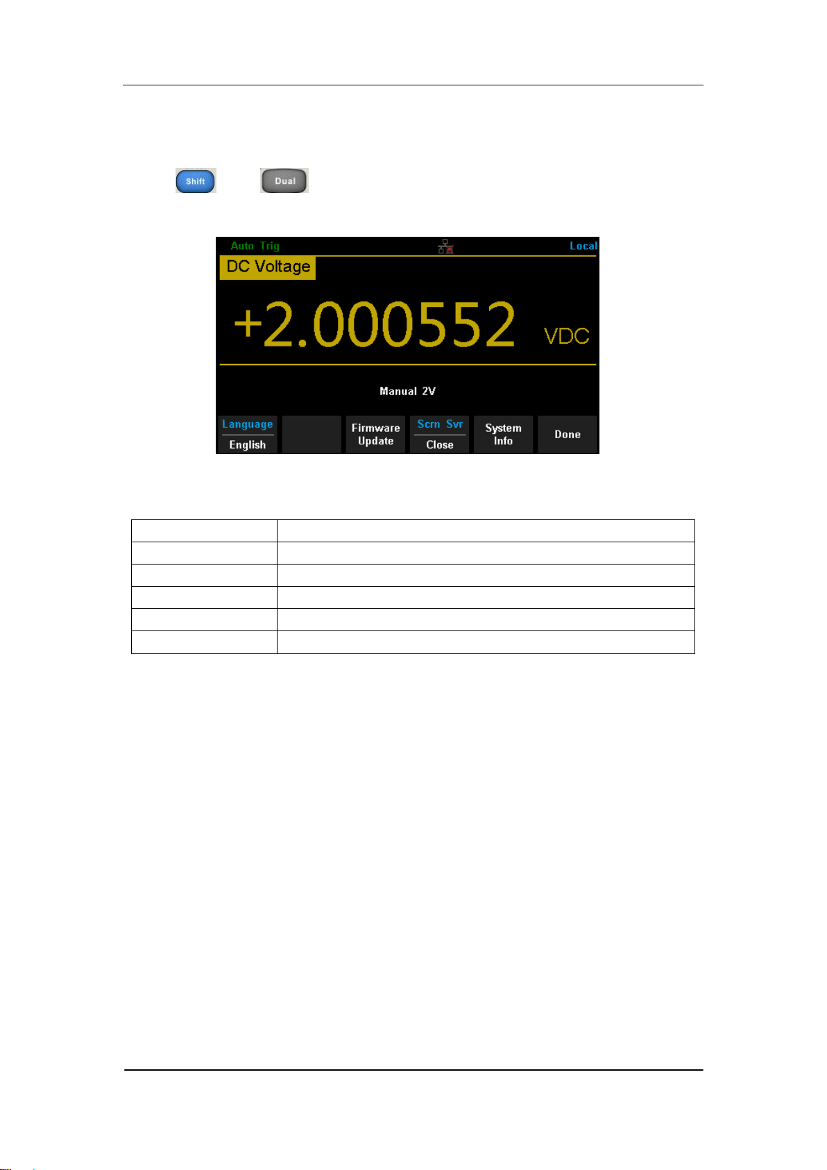
SIGLENT
SDM3065X Digital Multimeter 65
System Setup
Press and , then select【System Setup】to enter the following
interface.
Diagram 2- 38 System Setup Interface
Table 2- 6 System Settings Menu Description
Function Menu
Description
Language
Select the display interface language.
Firmware Update
Update software version,
Screen
Set up the screen protection function.
System Info
View system information.
Done
Return to the higher level menu.
1. Select language.
The Multimeter supports two kinds of languages, English and Chinese. Press
【Language】to select the Language of the menu..
2. Set up the time of screen protection.
Press【Screen】to set screen protection as 1 Min, 5 Mins, 15 Mins, 30 Mins,
1 Hour, 2 Hours or 5 Hours according to different demands. Activate the
screen saver program and screen saver will be on if no action is taken within
the time that you have selected. Press any button the resume.
3. View system information.
Press【System Info】to view system information, including startup times,
software version, hardware version, production ID and serial number, as
shown in the following diagram.
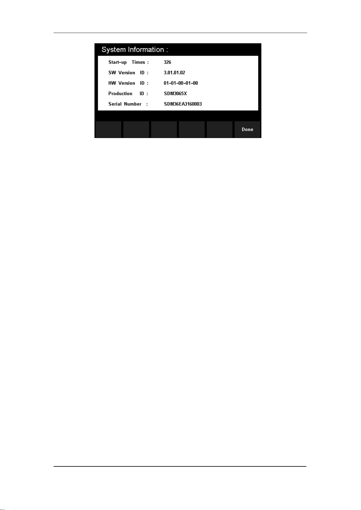
SIGLENT
66 SDM3065X Digital Multimeter
Diagram 2- 39 System Information
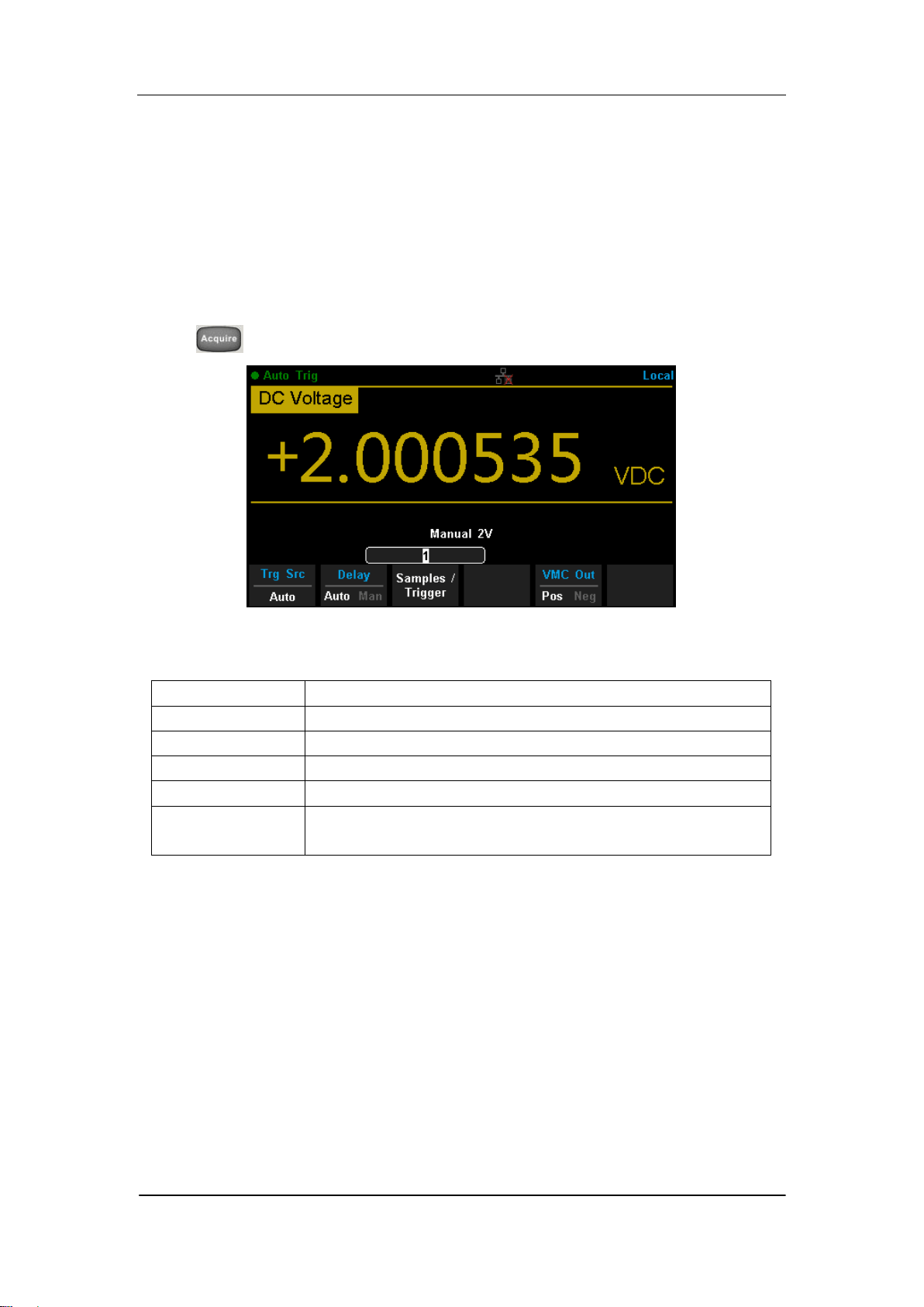
SIGLENT
SDM3065X Digital Multimeter 67
Acquire
Sampling is a process of acquiring and digitizing signal. The optional Trigger
methods of the Multimeter include Auto Trigger, Single Trigger and External
Trigger.
Press to enter the interface shown as the following diagram:
Diagram 2- 40 Acquire Interface
Table 2- 7 Function Menu of triggering parameter
Function Menu
Description
Trg Src
Set the source of trigger.
Slope
Set the slope polarity of external trigger.
Delay
Set the delay.
Samples/Trigger
Set the number of samples or trigger.
VMC Out
Set the polarity of output pulse signal when sampling
signal is finished.
SIGLENT
68 SDM3065X Digital Multimeter
Auto Trigger
Auto Trigger parameters that need to be set up include delay, samples/
trigger and VMC out.
Operating Steps:
1. Press , then select 【Trg Src】→【Auto】or press on the front
panel directly to enable Auto Trigger.
2. Set the delay.
Delay is the waiting time after the trigger signal is sent out and before the
auquiring starts. Press 【Delay】to select Auto or Manual mode. When
choosing Manual mode,Left and Right keys are used to switch the
number of a numerical value, Up and Down keys are used to change the
selected value.
3. Set the number of samples or trigger.
Press 【Samples/Trigger】to set the sample count. Left and Right keys are
used to switch the number of a numerical value, Up and Down keys are
used to change the selected value.
4. Set the VMC Out.
The Multimeter output a pulse signal through the VM COMP interface on
the rear panel after sampling signal is finished Press 【VMC Out】to choose
Positive or Negative polarity.
Sample Count
Sample Count indicates the count of point sampled while the
Multimeter getting a signal of Single Trigger.
The range of sampling point should be between 1 and 599999999.
The default value of Sample Count is 1.

SIGLENT
SDM3065X Digital Multimeter 69
Single Trigger
Single Trigger parameters that need to be set up include delay, samples
/trigger and VMC out.
Operating Steps:
1. Press , then select 【Trg Src】→【Single】or press on the
front panel directly to enable Single Trigger.
2. Set the delay.
Press 【Delay】to select Auto or Manual mode.
3. Set the number of samples or trigger.
Press 【Samples/Trigger】to set sample count.
4. Set the VMC Out.
The Multimeter output a pulse signal through the VM COMP interface on
the rear panel after sampling signal is finished.
Press 【VMC Out】to choose Positive or Negative polarity.

SIGLENT
70 SDM3065X Digital Multimeter
External Trigger
The external trigger signal will be input via EXT TRIG interface on the rear
panel. External trigger parameters that need to be set up include delay,
samples /trigger, slope and VMC out.
Operating Steps:
1. Press , then select 【Trg Src】→【Ext】enable External Trigger.
2. Set the polarity of slope.
Press 【Slope】to choose Positive or Negative polarity.
3. Set the delay.
Press 【Delay】to choose Auto or Manual mode.
4. Set the number of samples or trigger.
Press 【Samples/Trigger】to set sample count.
5. Set the VMC Out.
In External Trigger mode, the Multimeter could output a pulse signal
through the VM COMP interface on the rear panel after sampling signal is
finished.
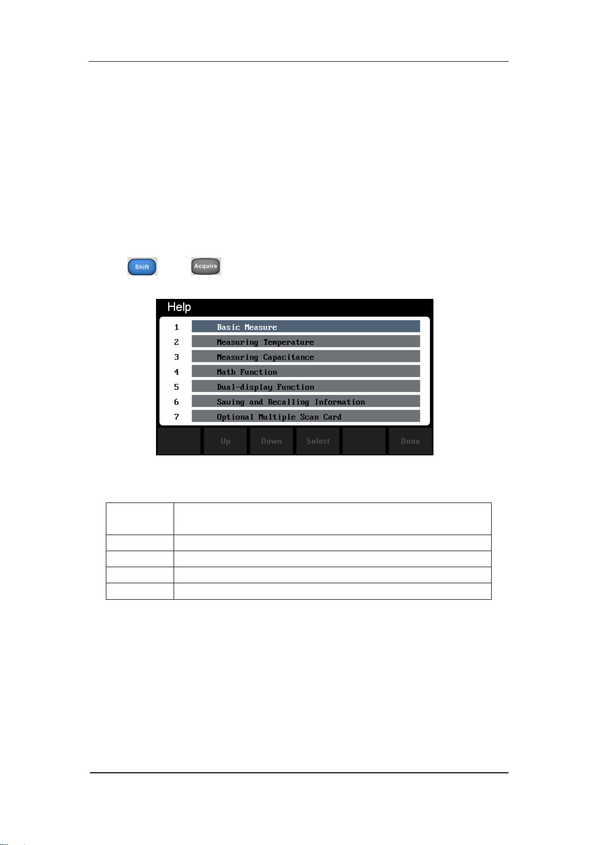
SIGLENT
SDM3065X Digital Multimeter 71
Help System
SDM3065X provides powerful built-in help system. You can recall help
information at any time during using the instrument. You also can get a
particularly help for every button on the front panel or menu softkey by using
the built-in help system. Or you can get help about familiar operations with
the help list.
Press and to enter the help list, as the following diagram
shows.
Diagram 2- 41 Help Menu
Table 2- 8 Help System Operating Menu
Function
Menu
Description
Up
Move up the cursor and select the help menu.
Down
Move down the cursor and select the help menu.
Select
Select the help information you want and read it.
Done
Return to the higher menu.
1. Basic Measure.
Get basic measurement types and methods to connect the leads in different
measurements.
2. Measuring Temperature.
Get the method to measure temperature.

SIGLENT
72 SDM3065X Digital Multimeter
3. Measuring Capacitance.
Get the method to measure temperature.
4. Math Function.
Introduce how to use the math function while you are measuring.
5. Dual-display Function.
Get the method to use the dual-display function while you are measuring.
6. Saving and Recalling Information.
Introduce how to store and recall the data/parameter/ sensors files.
7. Optional Multiple Scan Card.
Get help about operating optional multiple scan cards.
8. The convention and Tips of Softkeys.
Get help about the convention and tips of softkeys.
9. Technical Support.
Get the method to obtain technical support.
Explanation:
In the help menu interface, you also can move cursor and select the
corresponding menu by up and down direction keys and press ”OK” to
read the help information.
While reading help information, you also can look up and down the
information by up and down direction keys.
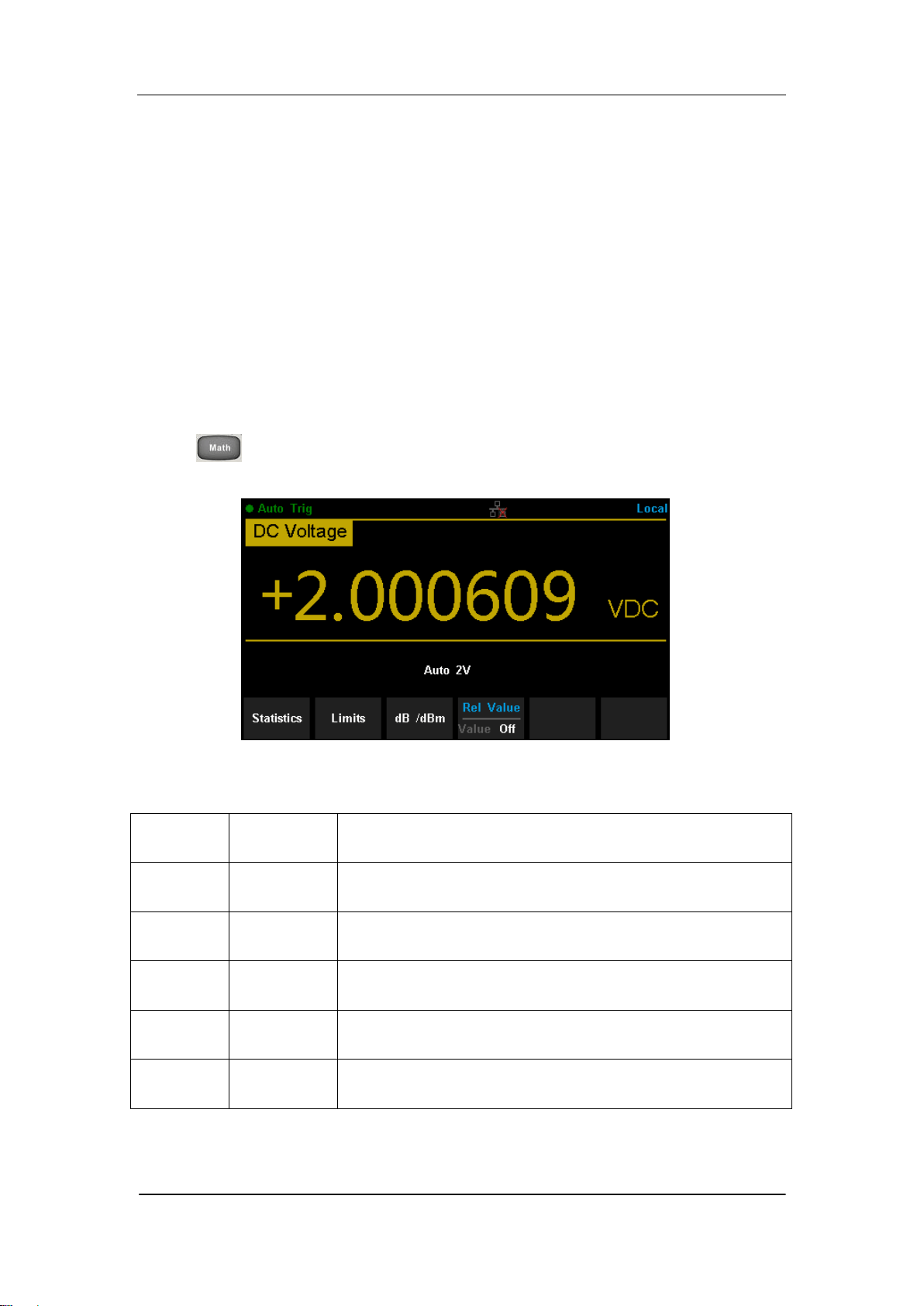
SIGLENT
SDM3065X Digital Multimeter 73
Math Function
The Multimeter provides five math functions: Statistics, Limits, dBm, dB and
Relative. Choose different math functions to meet different measurement
demands. Math functions can only be used in DC Voltage, AC Voltage, DC
Current, AC Current, Resistance, Frequency, Period and Temperature
measurement. Among these functions, dBm and dB are only used in DC
Voltage and AC Voltage measurement.
Press to show the operating menu of math functions on the screen, as
shown in the following diagram.
Diagram 2- 42 Math Function Menu
Table 2- 9 Math Function Menu Description
Function
Menu
Settings
Description
Statistics
Reading statistic functions, including: max, min,
average, span, std dev and samples.
Limits
The Limits function performs Pass/Fail testing
according to the specified upper and lower limits.
dBm
The dBm is based on a calculation of power delivered
to a reference resistance, 0dBm = 1mW.
dB
The dB measurement is the difference between the
input signal and a stored relative value.
Rel Value
Value/Off
Turn on the relative value function and set up the
value. Or turn off the function.

SIGLENT
74 SDM3065X Digital Multimeter
Explanations:
Math function can only be applicable to the main display.
If measurement function is changed, all math functions will be
closed except Statistics.
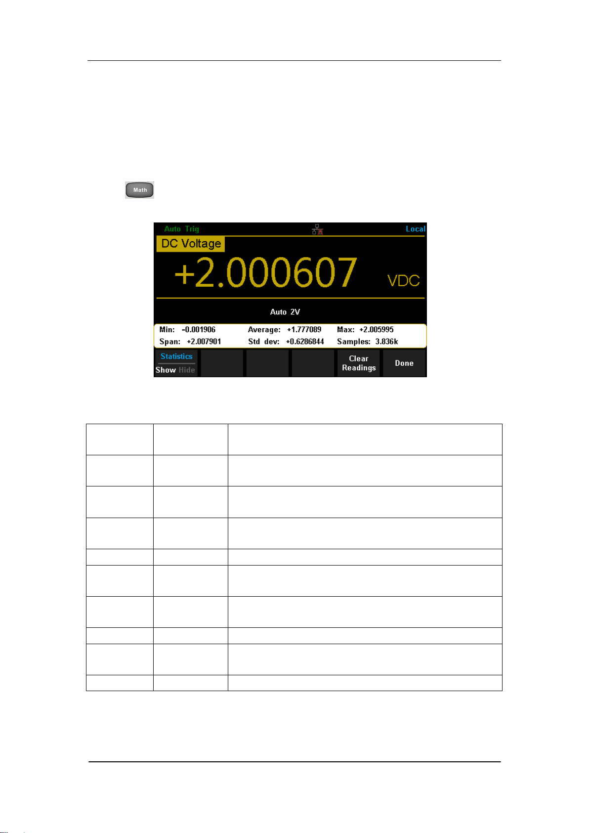
SIGLENT
SDM3065X Digital Multimeter 75
Statistics
There are many kinds of reading statistic functions, including: Max, Min,
Average, Standard deviation and so on.
Press →【Statistics】→【Show】 to enter the interface shown in the
following diagram.
Diagram 2- 43 Statistics
Table 2- 10 Statistic Measurement Menu Function Description
Function
Menu
Settings
Description
Min
Show the minimum statistics value of current
measurement.
Average
Show the average statistics value of current
measurement.
Max
Show the maximum statistics value of current
measurement.
Span
Show the span of current measurement.
Std dev
Show the std dev statistics value of current
measurement.
Samples
Show the maximum statistics value of current
measurement.
Statistics
Show/Hide
Show or hide the statistics function interface.
Clear
Readings
Clear all current readings and restart statistics.
Done
Return to the higher level menu.

SIGLENT
76 SDM3065X Digital Multimeter
Statistics Function:
In statistic function, the first reading is usually set to the maximum or
minimum value. When getting more readings, current displaying value
is always the maximum/minimum reading among all the measured
values.
The maximum, minimum, average and reading quantities are stored in
volatile memory.
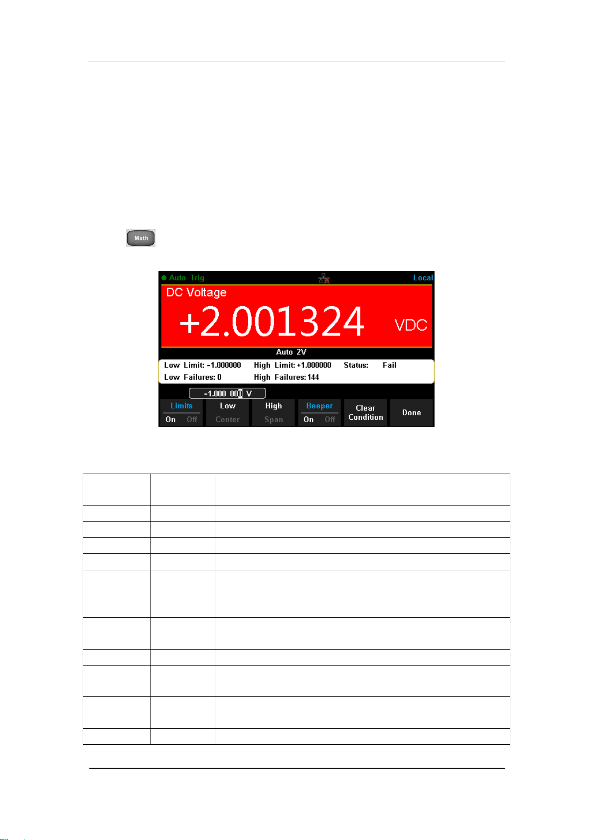
SIGLENT
SDM3065X Digital Multimeter 77
Limits
Limits function is available to prompt signals beyond ranges according to the
upper and lower parameters. Following are some measurement functions
which are able to do limit operation: DC Voltage, AC Voltage, DC Current, AC
Current, Resistance, Frequency, Period, Capacitance and Temperature.
Press →【Limits】→【On】 to enter the interface shown in the following
diagram.
Diagram 2- 44 Limits
Table 2- 11 Limits Measurement Menu Function Description
Function
Menu
Settings
Description
Limits
On/Off
Turn on or turn off the Limits function.
Low
Set the desired lower limit.
Center
Set the desired center value
High
Set the desired upper limit.
Status
Show the status of limit test.
Low
Failures
Show the times that reading is lower than the limit.
High
Failures
Show the times that reading is higher than the limit.
Span
Set the desired span.
Beeper
On/Off
When the beeper is on, if the reading is lower or
higher than limits, the instrument will beep once.
Clear
Condition
Clear all current readings and restart to test.
Done
Save all changes and return to the higher level menu.

SIGLENT
78 SDM3065X Digital Multimeter
1. How to Set Limits
Select 【High】,【Low】,【Center】or【Span】 and then switch to the needed
digit by Left or Right Direction keys and input numerical value by Up and Down
Direction keys.
2. Unit
The unit of Limits is decided by the current measurement function.
3. Over hint
When the reading is lower than the set lower limit, the color of main display
will switch blue to red.
When the reading is higher than the set higher limit, the color of main
display will switch blue to red.
When the reading is lower or higher than the set limits, the Beeper will
beep once. (The beeper is turned on.)
The range of Limits function:
The Limits range is -120% ~ +120% of the current measurement range.
The upper limit value should be always bigger than the lower limit
value.
The upper and lower values are stored in volatile memory. They will be
set to default values when the power is on.
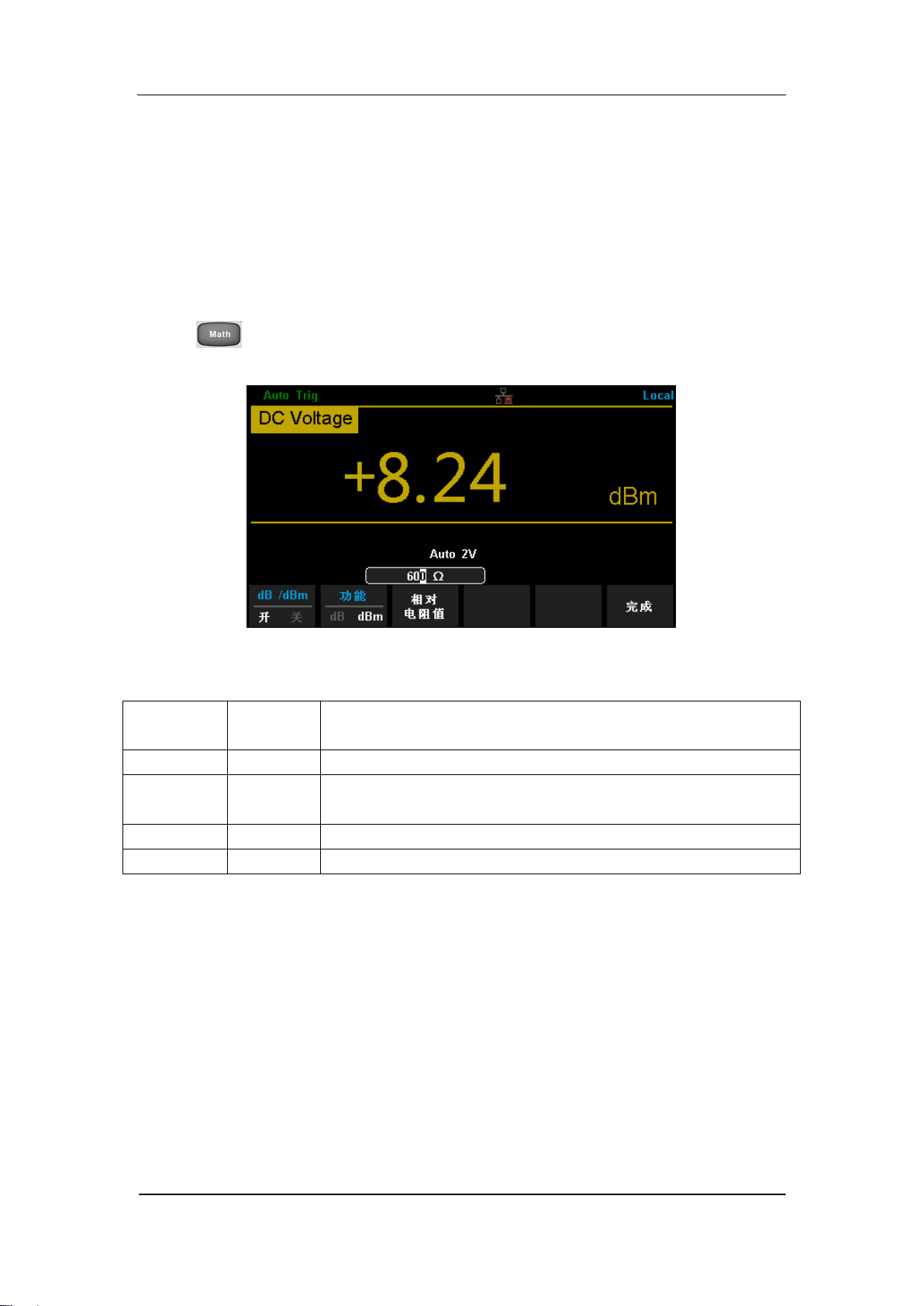
SIGLENT
SDM3065X Digital Multimeter 79
dBm
The dBm function is logarithmic and based on a calculation of power delivered
to a reference resistance, relative to 1 mill watt. Besides,this function only
applies to AC voltage and DC voltage measurements.
Press →【dB/dBm】→【On】and select【Function dBm】to enter the
interface shown in the following diagram.
Diagram 2- 45 dBm Function Interface
Table 2- 12 dB Measurement Function Menu Function Description
Function
Menu
Settings
Description
dB/dBm
On/Off
Turn on or turn off dB or dBm function.
Function
dBm
Open dBm function and the lower right corner of the
main display show “dBm”.
Ref R
Set the parameter via direction keys: 50Ω ~ 8000Ω.
Done
Save all changes and return to the higher level menu.
The computation method of the dBm:
When dBm function is turned on, the measured value of voltage is transformed
into dBm according to the following formula.
dBm = 10 x Log
10
[(Reading
2
/ R
REF
) / 0.001W]
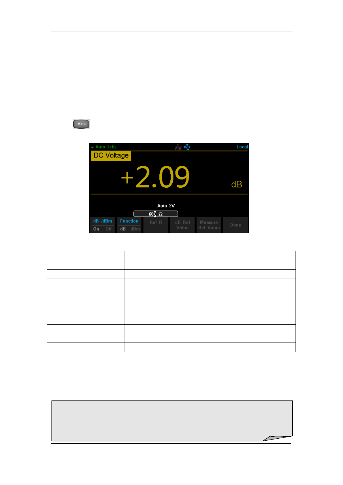
SIGLENT
80 SDM3065X Digital Multimeter
dB
Each dB measurement is different between the input signal and a stored
relative value, with both values converted to dBm. The dB function applies to
AC voltage and DC voltage measurements only.
Press →【 dB/dBm On】and select【Function dB】to enter the interface
shown in the following diagram.
Diagram 2- 45 dB Function Interface
Table 2- 13 dB Measurement Function Menu Function Description
Function
Menu
Settings
Description
dB/dBm
On/Off
Turn on or turn off dB or dBm function.
Function
dB
Open dB function and the lower right corner of the
main display show “dB”.
Ref R
Set the parameter via direction keys: 50Ω ~ 8000Ω.
dB Ref
Value
Set the referred value of dB.
Measure
Ref Value
Set the referred value of measurement.
Done
Save all changes and return to the higher level menu.
The computation method of the dB:
dB = 10 x Log
10
[(Reading
2
/ R
REF
) / 0.001W] – (dB setting value)
R
REF
expressed measuring the resistance value in the actual electric circuit.
Range of the dB setting value: -200 dBm ~ +200 dBm. The default is 0 dBm.
dB value:
Input a value in dB setting interface by direction button, and then store it as
dB setting value.
Settings of dB value are stored in volatile memory.

SIGLENT
SDM3065X Digital Multimeter 81
Relative Value
Relative value is used for relative measurement. Actual measurement reading
is the depression between measurement value and preset value.
The Multimeter allows operating for the following parameters: DC Voltage, AC
Voltage, DC Current, AC Current, Resistance, Frequency, Period,
Capacitance and Temperature.
Press →【Rel Value】to enter the interface shown in the following
diagram.
Diagram 2- 46 Relative Operation
Table 2- 14 Rel Value Operation Function Menu
Function
Menu
Description
Value
Select current measurement value as preset value.
Off
Turn off the relative operation function.
When Rel Value function is turned on, the result of relative measurement will
show on the screen.
Main display = Measurement value – Preset value
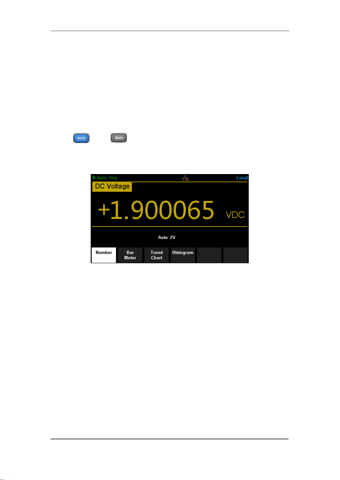
SIGLENT
82 SDM3065X Digital Multimeter
Display Mode
The Multimeter supports four types of way to view measured data: “Number”,
“Bar Meter” ”Trend Chart” and “Histogram”.
Number
Press and to open the menu of display mode and press
【Display】to enter the following interface. “Number” is always the selected
mode when the Multimeter is turned on.
Diagram 2- 47 Number Display Mode
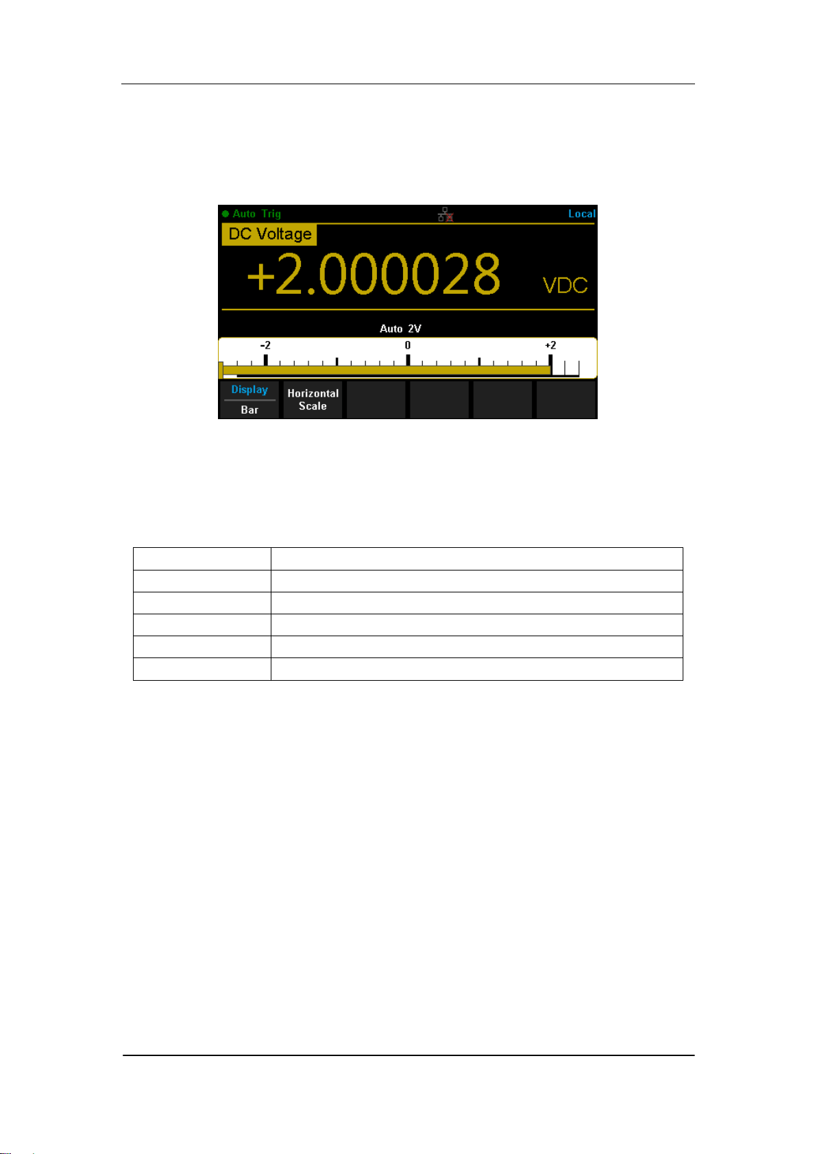
SIGLENT
SDM3065X Digital Multimeter 83
Bar Meter
Operating Steps:
1. Press【Bar Meter】to enter Bar Meter display mode.
Diagram 2- 48 Bar Meter Display Mode
2. Press【Horizontal Scale】to choose the way to set the vertical scale as
Default or Manual mode.
Table 2- 15 To Set the Vertical Scale of Bar Meter manually
Function Menu
Description
Low
Set the low value of horizontal scale.
High
Set the high value of horizontal scale.
Center
Set the center value of horizontal scale.
Span
Set the span of horizontal scale.
Done
Save all changes and return to the higher level menu.
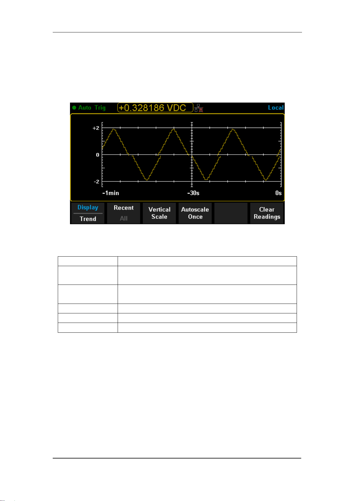
SIGLENT
84 SDM3065X Digital Multimeter
Trend Chart
Operating Steps:
1. Press【Trend Chart】to enter Trend Chart display mode.
Diagram 2- 49 Trend Chart Display Mode
Table 2- 16 Trend Chart Display Mode
Function Menu
Description
Display
Trend
Currently selected display mode is Trend Chart.
Recent
All
Show recent or all readings.
Horizontal Scale
Choose the mode of Horizontal Scale.
Autoscale Once
Automatically set the horizontal scale once.
Clear Readings
Clear all current readings and restart statistics.
2. Press【Horizontal Scale】to choose the way to set the horizontal scale as
Default , Auto or Manual mode.
Press【Auto】and the Multimeter will set the vertical scale automatically.
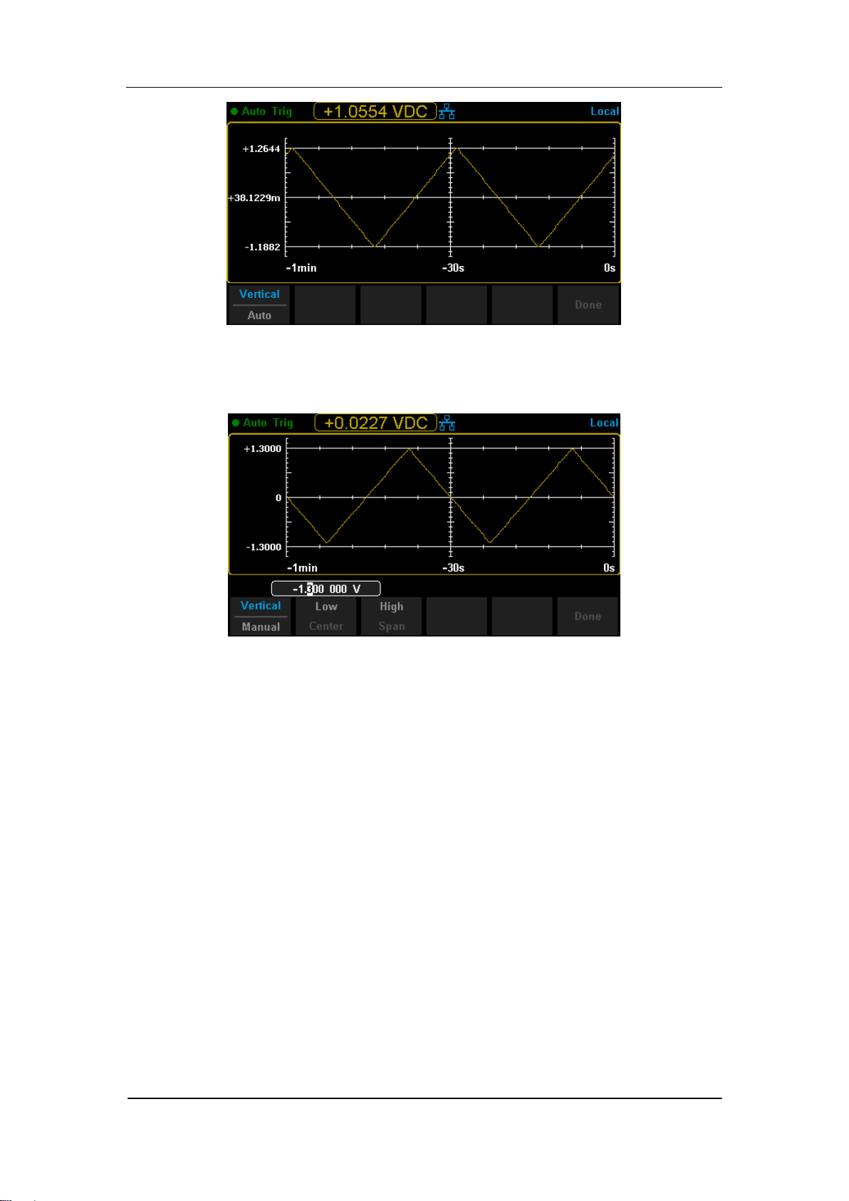
SIGLENT
SDM3065X Digital Multimeter 85
Diagram 2- 50 Auto Vertical Scale
Press【Manual】and you can set the vertical scale manually, as the following
diagram shows.
Diagram 2- 51 Manual Vertical Scale
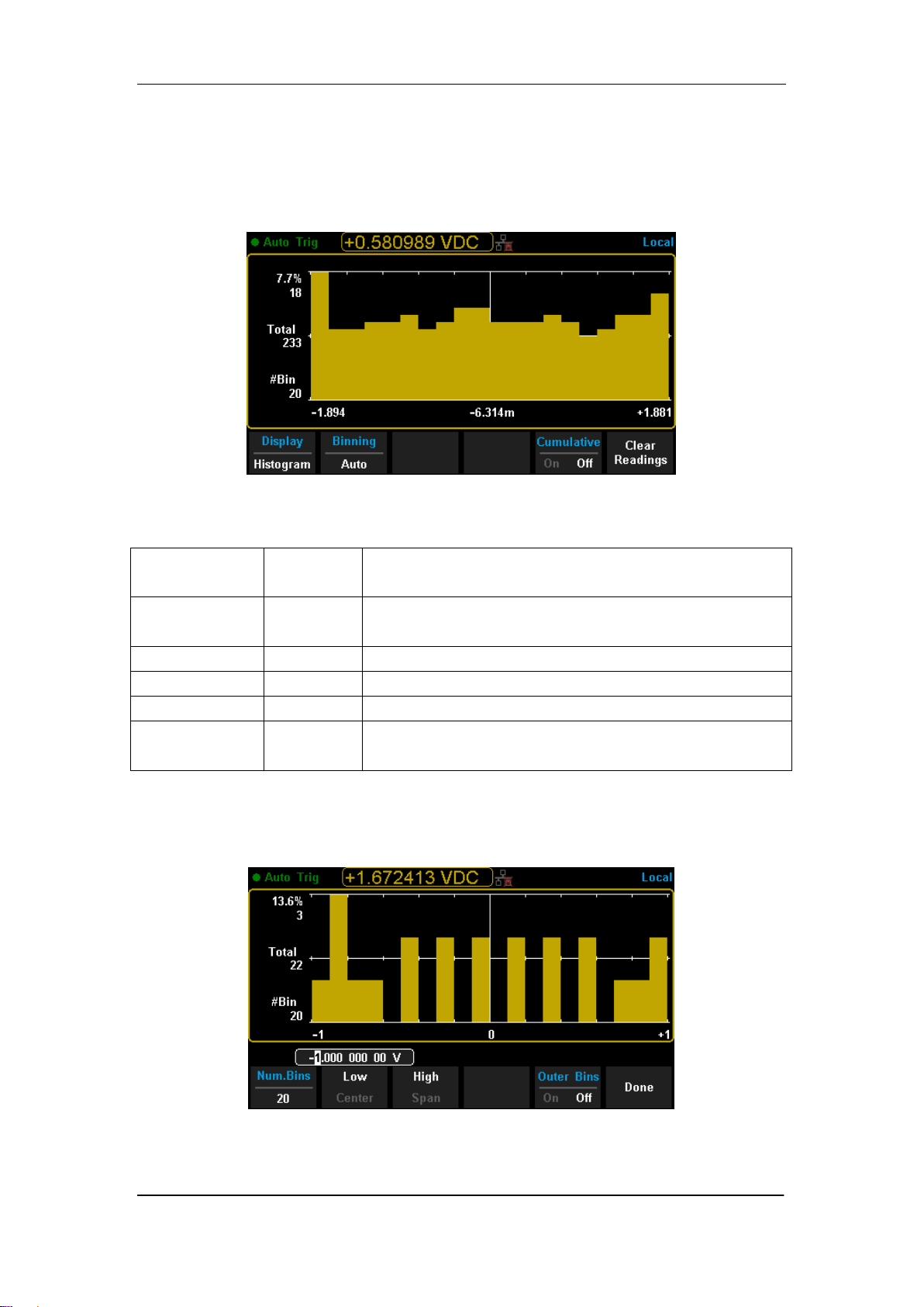
SIGLENT
86 SDM3065X Digital Multimeter
Histogram
Operating Steps:
1. Press【Histogram】to enter Histogram display mode.
Diagram 2- 52 Histogram Display Mode
Table 2- 17 Histogram Display Mode
Function
Menu
Settings
Description
Display
Histogram
Currently selected display mode is Histogram.
Binning
Set Binning as Auto or Manual mode.
Bin Set
Set the parameters of Bin.
Cumulative
On/Off
Turn on or off Cumulative function.
Clear
Readings
Clear all current readings and restart statistics.
2. Press【Binning】to choose the way to set Binning as Auto or Manual mode.
When in Manual mode, press【Bin Settings】to enter the following interface.
Diagram 2- 53 Bin Set Interface
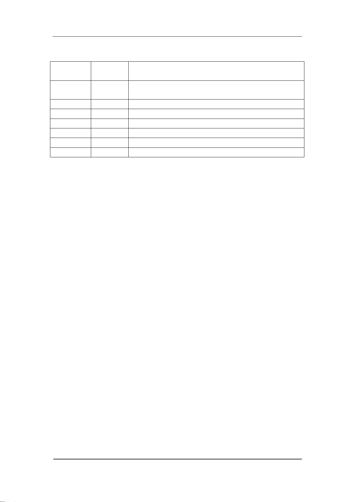
SIGLENT
SDM3065X Digital Multimeter 87
Table 2- 18 Bin Set
Function
Menu
Settings
Description
Num.Bins
Set the number of Bins, 10, 20, 40, 100, 200 or 400
selected.
Low
Set the low value of horizontal scale.
High
Set the high value of horizontal scale.
Center
Set the center value of horizontal scale.
Span
Set the span of horizontal scale.
Outer Bins
On/Off
Show the bins beyond the scope or not.
Done
Save all changes and return to the higher level menu.
SIGLENT
88 SDM3065X Digital Multimeter
Trigger
The Multimeter supports Trigger function. Press or on the front
panel to trigger the Multimeter by Auto or Single mode .Auto trigger is
considered as a default when the power is on.
Auto Trigger
Press on the front panel one time and Auto Trigger will be started to
capture continuous readings automatically. By the time, the black field of the
screen will show “● Auto Trigger”. Press again and the trigger is
stopped.
Single Trigger
Press on the front panel, Single Trigger will be started one time and
generate an effective reading. By the time, the black field of the screen will
show “● Single Trig”.
Explanation:
In Remote Mode, the black field just above the screen will show “● Imme Trig”.
Press to switch back to the local mode and the Multimeter will choose
Auto Trigger automatically.
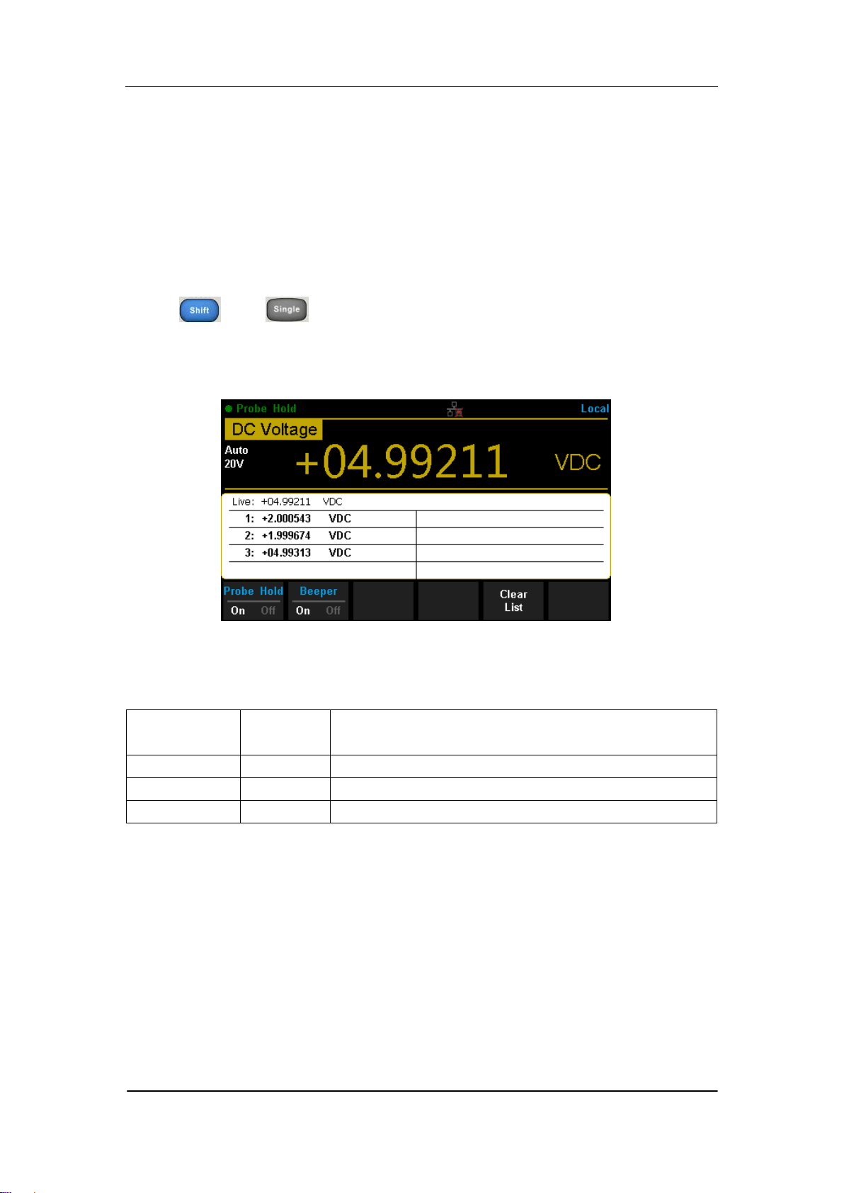
SIGLENT
SDM3065X Digital Multimeter 89
Hold Measurement Function
Hold Measurement function provides users with a stable reading on the
screen of the front panel. When the test leads are put away, the reading is
still held on the screen, which makes users can view measured history data.
Press and to open Hold measurement function interface, the
black field just above the screen will show “·Probe Hold”, as shown in the
following diagram.
Diagram 2- 54 Hold Measurement Function Interface
Table 2- 19 Hold Measurement Function
Function
Menu
Settings
Description
Probe Hold
On/Off
Turn on or off Probe Hold function.
Beeper
On/Off
Turn on or off the Beeper.
Clear List
Clear all current readings and restart to statistics.
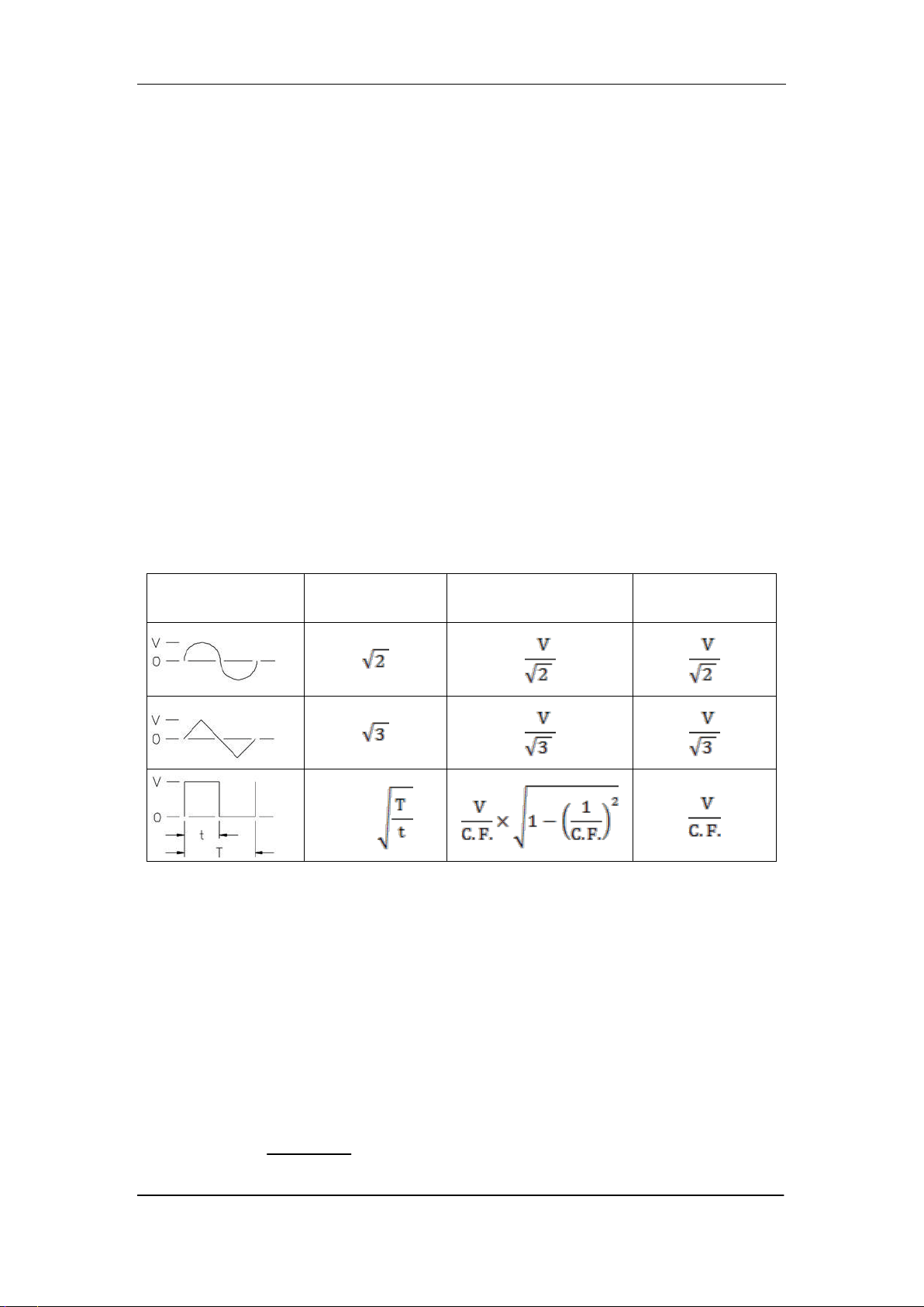
SIGLENT
90 SDM3065X Digital Multimeter
Chapter 3 Measurement Tutorial
True RMS AC Measurement
The AC measurement of the Multimeter has true RMS response. The power
dissipated in a resistor within a time is proportional to the square of the
measured true RMS voltage, independent of wave shape. The instrument can
accurately measure true RMS voltage or current, as long as the wave shape
contains negligible energy above the effective bandwidth.
The AC voltage and AC current functions measure the “AC coupled” true RMS
value, which is to measure the RMS value of the AC component (DC
component is rejected) of the input signal. For sine waves, triangle waves, and
square waves, the AC and AC+DC values are equal since these waveforms do
not contain a DC offset. See the following table 5-1.
Table 3- 1 True RMS AC Measurement of Sine, Triangle and Square waves
Waveform
Crest Factor
(C.F.)
AC RMS
AC+DC
RMS
Non-symmetrical waveforms, such as pulse trains, contain DC voltages which
are rejected by AC coupled true RMS measurements.
An AC coupled true RMS measurement is desirable in situations where you
are measuring small AC signals in the presence of DC offsets. For instance,
measuring AC ripple present on DC power supplies. There are situations,
however, where you might want to know the AC+DC true RMS value. You can
determine this value by combining results from DC and AC measurements as
the following shows. You should perform the DC measurement using 6.5 digit
mode for best AC rejection.
RMS
(AC+DC)
= √ AC
2
+ DC
2

SIGLENT
SDM3065X Digital Multimeter 91
Crest Factor Errors (non-sinusoidal inputs)
A common misconception is that "since an ac Multimeter is true RMS, its sine
wave accuracy specifications apply to all waveforms." Actually, the shape of
the input signal can dramatically affect measurement accuracy. A common
way to describe signal wave shapes is “crest factor”. Crest factor is the ratio of
the peak value to RMS value of a waveform.
Generally speaking, the greater the crest factor, the greater the energy
contained in high frequency harmonics. All Multimeters have errors that are
crest factor dependent. (The crest factor errors do not apply for input signals
below 100Hz.)
You can estimate the measurement error due to signal crest factor as shown
below:
Total Error=Error (Sine wave) + Error (Crest factor) + Error (Bandwidth)
Error (Sine wave): error for sine wave
Error (Crest factor): crest factor additional error.
Error (Bandwidth): estimated bandwidth error as shown below:
Bandwidth error = ×100%(% reading)
C.F.: signal crest factor
F: fundamental frequency of pulse
BW: effective bandwidth of the Multimeter
Example:
Calculate the approximate measurement error for a pulse train input with a
crest factor of 2 and a fundamental frequency of 20 kHz. For this example,
assume 1-year accuracy specifications of the Multimeter: ± (0.05%× reading +
0.03%×range).
Total Error = (0.05%×reading+0.03%×range) + (0.05%×range) +
(0.8%×reading)
=0.85%×reading + 0.08%×range
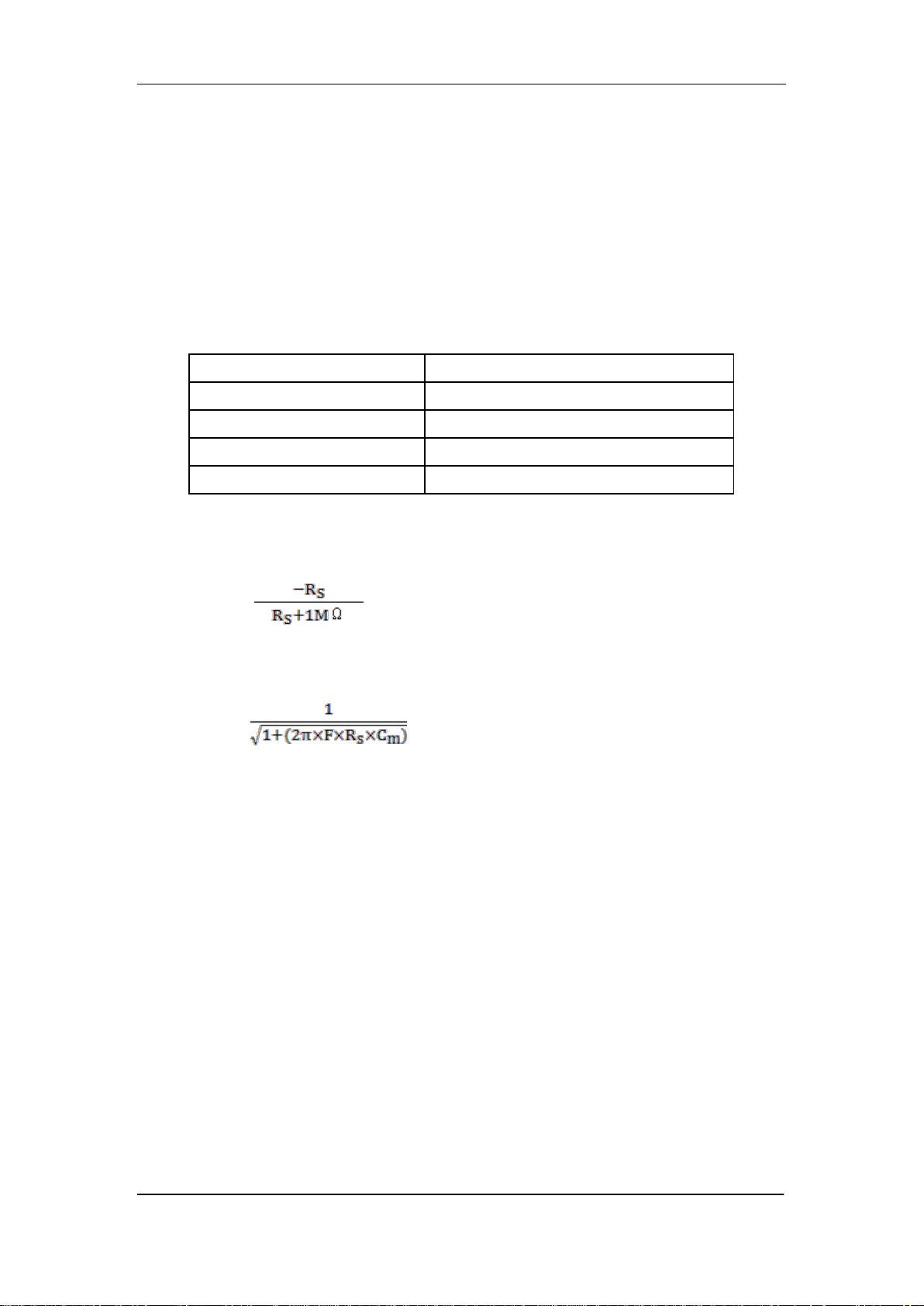
SIGLENT
92 SDM3065X Digital Multimeter
Loading Errors (AC Voltage)
In the AC Voltage function, the input of SDM3065X appears as a 1MΩ
resistance in parallel with 100pF of capacitance. The test lead that you use to
connect signals to the Multimeter will also add additional capacitance and
loading. The approximate input resistances of the Multimeter at different
frequencies are listed in the following table.
Table 5- 2 Approximate Input Resistances at Different Frequencies
Input Frequency
Input Resistance
100Hz
1MΩ
1kHz
850kΩ
10kHz
160kΩ
100kHz
16kΩ
For low frequencies:
Error(%)= ×100%
For high frequencies:
Error(%)=[ -1] ×100%
F: input frequency
R
s
: source resistance
C
m
: input capacitance (100pF) plus test lead capacitance

SIGLENT
SDM3065X Digital Multimeter 93
Chapter 4 General Troubleshooting
The following is a list of the troubles that you may meet while using the
Multimeter and their solutions. Please handle as the corresponding steps
when meeting these troubles. If you still can‟t handle them, please contact
SIGLENT in time.
1. If the screen of the Multimeter is still dark with nothing displaying
after pressing the power key:
(1) Check if the power has been connected correctly.
(2) Check if the main power switch on the back panel has been turned on
already.
(3) Check if the power fuse has blown. Replace it as desired if it has blown.
(4) Restart the Multimeter after all above steps have been done.
(5) If the instrument still can‟t start up properly, please contact SIGLENT.
2. The reading doesn’t change when connecting an AC current signal:
(1) Check if the test lead has been connected to the current jack or LO jack
correctly.
(2) Check if the fuse in the current location on the back panel has blown.
(3) Check if the measuring location has switched to the DCI or ACI place
correctly.
(4) Check if the input is ACI but the measuring location is in DCI place.
3. The reading doesn’t change when connecting a DC current signal:
(1) Check if the test lead has been connected to the current jack or LO jack
correctly.
(2) Check if the fuse in the current location on the back panel has blown.
(3) Check if the measuring location has switched to the DCI or ACI place
correctly.
(4) Check if the input is DCI but the measuring location is in ACI place.
4. USB Disks can’t be recognized by the instrument.
(1) Check if the USB disk can work properly.
(2) Make sure the used USB disk is of Flash type. The instrument doesn‟t
support USB disks of hard disk type.
(3) Check if the capacity of the used USB disk is too large. The Multimeter is
recommended not to use USB disks which exceed 8GB.
(4) After restarting the instrument, insert the USB disk again to inspect.
(5) If you still can‟t use the USB disk properly, please contact SIGLENT.

SIGLENT
94 SDM3065X Digital Multimeter
Chapter 5 Appendix
Appendix A: Accessories
Standard Accessories:
A Power Cord that fits the standard of destination country.
Two test leads (black and red)
An USB Cable
One backup fuses
A Quick Start
A CD-ROM
NOTE:
We suggest that the length of USB data wire and LAN cable connected to
the instrument should be less than 3m to avoid affecting the product
performance.
All the accessories are available by contacting your local SIGLENT
office.

SIGLENT
SDM3065X Digital Multimeter 95
Appendix B: Warranty summary
SIGLENT warrants that the products that it manufactures and sells will be
free from defects in materials and workmanship for a period of three years
from the date of shipment from an authorized SIGLENT distributor. If a
product proves defective within the respective period, SIGLENT will provide
repair or replacement as described in the complete warranty statement.
To arrange for service or obtain a copy of the complete warranty statement,
please contact your nearest SIGLENT sales and service office. Except as
provided in this summary or the applicable warranty statement, SIGLENT
makes no warranty of any kind, express or implied, including without
limitation the implied warranties of merchantability and fitness for a particular
purpose. In no event shall SIGLENT be liable for indirect, special or
consequential damages.

SIGLENT
96 SDM3065X Digital Multimeter
Appendix C: Contact SIGLENT
SIGLENT TECHNOLOGIES CO., LTD.
Address: 3F, NO.4 building, Antongda Industrial Zone, 3rd
Liuxian Road, 68th District, Baoan District, Shenzhen,
P.R. China
Tel: +86-755-36615186
Fax: +86-755-3591582
Post Code: 518101
E-mail: sales@siglent.com
Http://www.siglent.com