
Loading ...
Loading ...
Loading ...
INSTA LLAiTION INSTRUCTIONS 25
Connecfing Elecfric Dryers (conf.}
USA only
_WARNING
• Connect the power cord to the terminal block.
Connect each power cord wire to the terminal block
screw that has the same colored wire. For example,
connect the black power cord wire to the terminal
block screw with the black wire.
Failure to follow these instructions may result in a
short, overload, fire or death.
• Grounding through the neutral conductor is
prohibited for: (1) new branch-circuit installations,
(2) mobile homes, (3} recreational vehicles, and
(4) areas where local codes prohibit grounding
through the neutral conductor.
Four-wire connection for electric dryers: Direct wire
• A 4-wire connection is required for all mobile and
manufactured home installations, as well as all new
construction after January 1, 1996.
. A UL-listed strain relief is required.
1. Remove 5 inches (12.7 cm) of the outer covering from
the wire. Remove S inches of insulation from the
ground wire. Cut offapproximately 11/2inches (3.8 cm)
from the other three wires and strip 1 inch (2.5 cm)
insulation from each wire. Bend the ends of the three
shorter wires into a hook shape.
1" (2.5 crn)
I---t
__ Ground Wire
(12.ST'cm)
2. Remove the terminal block access cover on the upper
back of the dryer. Install a UL-listed strain relief into
the power cord through-hole; then thread the power
cable prepared in Step 1 through the strain reliefl
Term na
I Block
?@__ | _UL-Listed
L _ --_ ,_--_ Strain Relief
UL-Listed 4-Wire /
Power Cord
. Use UL-listed 4-wire #10 AWG-minimum copper
conductor cable.
. Allow at least S ft. (1.S m) length to allow for removal
and reinstallation of the dryer.
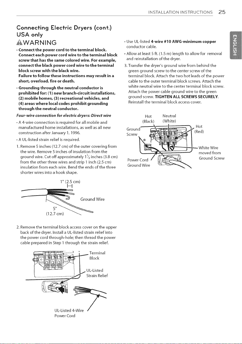
3. Transfer the dryer's ground wire from behind the
green ground screw to the center screw of the
terminal block. Attach the two hot leads of the power
cable to the outer terminal block screws. Attach the
white neutral wire to the center terminal block screw.
Attach the power cable ground wire to the green
ground screw, TIGHTEN ALL SCREWS SECURELY.
Reinstall the terminal block access cover.
Hot Neutral
(Black) (White)
.ot
Screw i (Red)
--- White Wire
moved from
PowerCord " _\_ Ground Screw
Ground Wire ,_x.._ "_
Loading ...
Loading ...
Loading ...