p/n: P-164000669
Revision 10
Eaton 9PXM UPS
4–20kVA Users Guide
Eaton 9PXM UPS

Eaton reserves the right to change specifications without prior notice. Eaton reserves the right to change specifications without prior
notice. Modbus is a registered trademark of Schneider Automation, Inc. MOXA is a registered trademark and MGate is a trademark of
MOXA, Inc. Spiralock is a registered trademark of Spiralock Corporation. KIRK is a registered trademark of Kirk Key Interlock company,
LLC, a subsidiary of Halma plc. National Electrical Code and NEC are registered trademarks of National Fire Protection Association, Inc.
ERIFLEX and FLEXIBAR are registered trademark of Erico International Corporation. All other trademarks are property of their respective
companies. All other trademarks are property of their respective companies.
©Copyright 2020 Eaton, Raleigh, NC, USA. All rights reserved. No part of this document may be reproduced in any way without the
express written approval of Eaton.
CCllaassss AA EEMMCC SSttaatteemmeennttss
FCC Part 15
NOTE This equipment has been tested and found to comply with the limits for a Class
A digital device, pursuant to part 15 of the FCC Rules. These limits are designed
to provide reasonable protection against harmful interference when the
equipment is operated in a commercial environment. This equipment
generates, uses, and can radiate radio frequency energy and, if not installed and
used in accordance with the instruction manual, may cause harmful
interference to radio communications. Operation of this equipment in a
residential area is likely to cause harmful interference in which case the user
will be required to correct the interference at his own expense.
ICES-003
This Class A Interference Causing Equipment meets all requirements of the Canadian Interference
Causing Equipment Regulations ICES 003.
Cet appareil numérique de la classe A respect et outes les exigences du Reglement sur le matériel
brouilleur du Canada.
IEC 62040-2
Some configurations are classified under IEC 62040-2 as “C2 UPS for Unrestricted Sales
Distribution.”

SSppeecciiaall SSyymmbboollss
The following are examples of symbols used on the product to alert you to important information:
RISK OF ELECTRIC SHOCK - Observe the warning associated with the risk of
electric shock symbol.
CAUTION: REFER TO OPERATOR'S MANUAL - Refer to your operator's
manual for additional information, such as important operating and maintenance
instructions.
This symbol indicates that you should not discard the product in the trash. This
product must be disposed of properly. For more information, contact your local
recycling/reuse or hazardous waste center.
This symbol indicates that you should not discard waste electrical or electronic
equipment (WEEE) in the trash. For proper disposal, contact your local recycling/
reuse or hazardous waste center.
!
IMPORTANT
To ensure you have the most up-to-date content and information for this product, please review the
latest manual revision on our website, Eaton.com/9PXM .


4–20kVA Users Guide P-164000669 4–20kVA Users Guide P-164000669—Rev 10 v
TTaabbllee ooff CCoonntteennttss
11 IInnttrroodduuccttiioonn....................................................................................................................................................................................................................................................................................................11
1.1 Introduction...............................................................................................................................................1
1.2 Safety Warnings.........................................................................................................................................1
1.3 Physical Features .......................................................................................................................................3
22 IInnssttaallllaattiioonn SSeettuupp ....................................................................................................................................................................................................................................................................................99
2.1 Preparing for Installation...............................................................................................................................9
2.2 Equipment Clearances.................................................................................................................................9
2.3 Location Requirements................................................................................................................................9
2.4 UPS Setup ................................................................................................................................................9
2.5 Anchor Bracket Installation ......................................................................................................................... 11
2.6 Rack-Mount Installation ............................................................................................................................. 12
33 UUPPSS WWiitthh EExxtteerrnnaall BByyppaassss IInnssttaallllaattiioonn .................................................................................................................................................................................................................... 1155
3.1 Installation of the UPS with an External Bypass Switch ..................................................................................... 15
3.2 Circuit Breaker Input Ratings....................................................................................................................... 16
3.3 UPS Connections ..................................................................................................................................... 17
3.4 BPM Signal Input Wire Routing.................................................................................................................... 22
3.5 System Wiring Diagrams............................................................................................................................ 25
3.6 Bypass Overview ..................................................................................................................................... 28
3.7 No Break Transfer from UPS Mode to Service Mode ........................................................................................ 29
3.8 Lock-out/Tag-out ...................................................................................................................................... 30
3.9 No Break Transfer from Service Bypass to UPS Mode ...................................................................................... 31
44 UUPPSS EElleeccttrriiccaall IInnssttaallllaattiioonn........................................................................................................................................................................................................................................................ 3355
4.1 UPS Input Current Ratings.......................................................................................................................... 35
4.2 UPS Electrical Installation ........................................................................................................................... 37
4.3 System Wiring Diagram ............................................................................................................................. 40
55 BBaatttteerryy CCaabbiinneett IInnssttaallllaattiioonn.................................................................................................................................................................................................................................................... 4433
5.1 Battery Cabinet Options............................................................................................................................. 43
5.2 Standard Battery Cabinet Installation ............................................................................................................ 43
5.3 Connected Battery Cabinet With No AC Input................................................................................................. 46
5.4 Connected Battery Cabinet With 120VAC Input............................................................................................... 49
5.5 Connected Battery Cabinet With Split Phase Input........................................................................................... 53
66 UUPPSS SSttaarrttuupp ................................................................................................................................................................................................................................................................................................ 5599
6.1 UPS Startup ............................................................................................................................................ 59
6.2 UPS Startup Without an External Bypass Switch ............................................................................................. 61
6.3 Startup for Units Installed with an Eaton BPM Bypass Switch ............................................................................ 62
6.4 Startup for Units installed with a BPE Type Switch........................................................................................... 63
6.5 Initial Startup Parameters ........................................................................................................................... 65

vi 4–20kVA Users Guide P-164000669 4–20kVA Users Guide P-164000669—Rev 10
77 OOppeerraattiioonn........................................................................................................................................................................................................................................................................................................ 6677
7.1 Normal Operation ..................................................................................................................................... 67
7.2 UPS Standby Mode................................................................................................................................... 67
7.3 UPS Shutdown ........................................................................................................................................ 67
7.4 Operating Modes ..................................................................................................................................... 67
7.4.1 Online Mode...................................................................................................................................... 67
7.4.2 Battery Mode..................................................................................................................................... 68
7.4.3 Low Battery Warning........................................................................................................................... 68
7.4.4 Bypass Mode..................................................................................................................................... 68
7.5 Return of AC Input Power........................................................................................................................... 69
7.6 Configuring Bypass Settings ....................................................................................................................... 69
7.7 Configuring Battery Settings ....................................................................................................................... 70
7.7.1 Advanced Battery Management............................................................................................................. 70
7.7.2 Auto Battery Test................................................................................................................................ 70
7.7.3 Low Battery Warning........................................................................................................................... 70
7.7.4 External Battery Setting ....................................................................................................................... 70
7.7.5 Deep Discharge Protection ................................................................................................................... 70
7.8 Retrieving the Event Log ............................................................................................................................ 70
7.9 Retrieving the Fault Log ............................................................................................................................. 70
7.10 Control Panel Operation ........................................................................................................................... 70
7.11 Display Functions.................................................................................................................................... 71
7.12 LCD Description ..................................................................................................................................... 72
7.13 Display Status Indicators .......................................................................................................................... 72
7.14 Changing Parameter Settings .................................................................................................................... 73
7.15 Display Menu Screens ............................................................................................................................. 73
88 CCoommmmuunniiccaattiioonn ...................................................................................................................................................................................................................................................................................... 8877
8.1 Intelligent Power Manager.......................................................................................................................... 87
8.2 Optional Interface Kits ............................................................................................................................... 87
8.3 Communication Ports ................................................................................................................................ 87
8.4 Dedicated Input Signals ............................................................................................................................. 88
8.5 DB-9 Communication Port .......................................................................................................................... 90
8.6 Communication Slots ................................................................................................................................ 90
99 MMaaiinntteennaannccee.............................................................................................................................................................................................................................................................................................. 9933
9.1 Routine Maintenance ................................................................................................................................ 93
9.2 Storage Temperature ................................................................................................................................ 93
9.3 External Bypass Switch (Make Before Break Only) Operation............................................................................. 93
9.4 Battery Replacement................................................................................................................................. 94
9.5 Power Module Replacement....................................................................................................................... 95
9.6 UPS Firmware Upgrade ............................................................................................................................. 96
1100 SSppeecciiffiiccaattiioonnss ...................................................................................................................................................................................................................................................................................... 9977
Table of Contents

4–20kVA Users Guide P-164000669 4–20kVA Users Guide P-164000669—Rev 10 vii
10.1 Nominal Electrical Input and Output ............................................................................................................ 97
10.2 Combined UPM Power Ratings.................................................................................................................. 97
10.3 Circuit Breakers ..................................................................................................................................... 98
10.4 Environmental and Safety ......................................................................................................................... 98
10.5 Battery Ratings....................................................................................................................................... 99
10.6 Output Run Times................................................................................................................................... 99
10.7 Weights and Dimensions.......................................................................................................................... 99
10.8 Output Receptacles............................................................................................................................... 100
10.9 Receptacle Circuit Breaker Ratings ........................................................................................................... 101
1111 TTrroouubblleesshhoooottiinngg................................................................................................................................................................................................................................................................................110033
11.1 Troubleshooting.................................................................................................................................... 103
11.2 Service and Support .............................................................................................................................. 106
11.3 Two-Year Limited Warranty..................................................................................................................... 106
Table of Contents

viii 4–20kVA Users Guide P-164000669 4–20kVA Users Guide P-164000669—Rev 10
Table of Contents

4–20kVA Users Guide P-164000669 4–20kVA Users Guide P-164000669—Rev 10 ix
LLiisstt ooff FFiigguurreess
Figure 1. Eight and Twelve-Slot Cabinets ( Front View) .......................................................................................3
Figure 2. Twelve-Slot Rear View Access..........................................................................................................4
Figure 3. Power Modules and Battery Slots......................................................................................................5
Figure 4. Battery Modules per Slot .................................................................................................................6
Figure 5. Uninterruptible Power Module ..........................................................................................................6
Figure 6. UPS Control Panel ..........................................................................................................................7
Figure 7. UPS on Shipping Pallet .................................................................................................................. 10
Figure 8. Moving the UPS from the Pallet ...................................................................................................... 11
Figure 9. Floor Anchor Bracket Installation ..................................................................................................... 12
Figure 10. Rack-Mount Ear installation ............................................................................................................ 13
Figure 11. Rack Tray Location ....................................................................................................................... 13
Figure 12. Remove Cabinet from Castor Tray ................................................................................................... 14
Figure 13. Securing the UPS in the Rack.......................................................................................................... 14
Figure 14. Typical Installation with a Bypass Switch........................................................................................... 15
Figure 15. BPM Bypass Bottom .................................................................................................................... 17
Figure 16. UPS AC Power Terminal Access...................................................................................................... 18
Figure 17. Split-Phase Power Modules............................................................................................................ 19
Figure 18. UPS Input and Output Terminals ..................................................................................................... 20
Figure 19. Bypass Switch Wiring Label and Terminal Blocks ................................................................................ 21
Figure 20. UPS Input Control Signal Wiring for Maintenance Bypass ..................................................................... 22
Figure 21. BPE to UPS Connector .................................................................................................................. 23
Figure 22. Three-Pin BPM to UPS Connector.................................................................................................... 23
Figure 23. Forced and Maintenance Bypass Screens ......................................................................................... 24
Figure 24. Wiring Diagram- UPS with External Bypass Switch (BPM) (L1, L2, N) ...................................................... 26
Figure 25. Wiring Diagram- UPS with External Bypass Switch (BPE) (L1, L2, N) ....................................................... 27
Figure 26. Bypass Switch Positions................................................................................................................ 28
Figure 27. Bypass From UPS to LINE.............................................................................................................. 30
Figure 28. Bypass From LINE to SERVICE ....................................................................................................... 30
Figure 29. LOTO Feature ............................................................................................................................. 31
Figure 30. From SERVICE to LINE.................................................................................................................. 32
Figure 31. From LINE to UPS ........................................................................................................................ 32
Figure 32. Typical Installation without a Bypass Switch....................................................................................... 35
Figure 33. UPS Power Terminals ................................................................................................................... 37
Figure 34. Split-Phase Power Modules............................................................................................................ 38
Figure 35. UPS Input and Output Terminal Connections...................................................................................... 39
Figure 36. UPS with No External Bypass (L1,L2,N) ............................................................................................ 41
Figure 37. Standard EBM Front and Back ........................................................................................................ 44
Figure 38. Standard EBM to UPS Connections.................................................................................................. 45
Figure 39. EBM Emergency Disconnect Switch ................................................................................................ 46

x 4–20kVA Users Guide P-164000669 4–20kVA Users Guide P-164000669—Rev 10
Figure 40. Connected EBM Front And Back ..................................................................................................... 47
Figure 41. Connected EBM (No AC Input Option) .............................................................................................. 48
Figure 42. EBM Emergency Disconnect Switch ................................................................................................ 49
Figure 43. Connected EBM Front And Back ..................................................................................................... 50
Figure 44. Connected EBM (120V AC Option)................................................................................................... 51
Figure 45. UPS Input Control Signal Wiring (For External Controls) ........................................................................ 52
Figure 46. Securing The CAN Ground Wire ...................................................................................................... 52
Figure 47. EBM Emergency Disconnect Switch ................................................................................................ 53
Figure 48. Connected EBM Front And Back ..................................................................................................... 54
Figure 49. Connected EBM ( Split Phase Input)................................................................................................. 55
Figure 50. UPS Input Control Signal Wiring (For External Controls) ........................................................................ 56
Figure 51. Securing The CAN Ground Wire ...................................................................................................... 56
Figure 52. EBM Emergency Disconnect Switch ................................................................................................ 57
Figure 53. Inserting the Modules ................................................................................................................... 60
Figure 54. EBM Battery Modules and Charger .................................................................................................. 60
Figure 55. Communication Ports.................................................................................................................... 61
Figure 56. UPS Control Panel ........................................................................................................................ 71
Figure 57. LCD Display Status Indicators ......................................................................................................... 72
Figure 58. Display Status Indicators................................................................................................................ 73
Figure 59. Start Screen................................................................................................................................ 74
Figure 60. Status Screen Menu ..................................................................................................................... 74
Figure 61. Measurements Menu ................................................................................................................... 75
Figure 62. Control Menu .............................................................................................................................. 76
Figure 63. Local Setting Menu ...................................................................................................................... 77
Figure 64. In/Out Settings Menu.................................................................................................................... 78
Figure 65. On/Off Settings Menu................................................................................................................... 79
Figure 66. Battery Settings Menu .................................................................................................................. 80
Figure 67. Input Signals Menu....................................................................................................................... 81
Figure 68. Comm Settings Menu ................................................................................................................... 82
Figure 69. Password Menus ......................................................................................................................... 83
Figure 70. Event Log................................................................................................................................... 83
Figure 71. Fault Log Menu ........................................................................................................................... 83
Figure 72. Identification Menu....................................................................................................................... 84
Figure 73. Register Product Menu ................................................................................................................. 85
Figure 74. UPS Communications Ports ........................................................................................................... 88
Figure 75. EBM Communication Port.............................................................................................................. 88
Figure 76. Normally Open Connections ........................................................................................................... 89
Figure 77. EPO Normally Closed Connections .................................................................................................. 89
Figure 78. Battery Replacement .................................................................................................................... 94
Figure 79. Power Module Replacement .......................................................................................................... 95
Figure 80. Compatible Output Receptacles .................................................................................................... 100
List of Figures

4–20kVA Users Guide P-164000669 4–20kVA Users Guide P-164000669—Rev 10 xi
LLiisstt ooff TTaabblleess
Table 1. Recommended Breaker Sizes .......................................................................................................... 16
Table 2. Recommended Wire Sizes .............................................................................................................. 16
Table 3. Bypass Switch Positions ................................................................................................................. 29
Table 4. BPM Dimensions .......................................................................................................................... 33
Table 5. UPS Recommended Breaker Sizes.................................................................................................... 36
Table 6. UPS Recommended Wire Sizes........................................................................................................ 36
Table 7. Electrical Input and Output .............................................................................................................. 97
Table 8. Power Ratings .............................................................................................................................. 97
Table 9. Circuit Breaker Sizes ...................................................................................................................... 98
Table 10. Environmental and Safety................................................................................................................ 98
Table 11. Battery Ratings ............................................................................................................................. 99
Table 12. Weights and Dimensions ................................................................................................................ 99
Table 13. Receptacle Circuit Breaker Ratings.................................................................................................. 101
Table 14. Typicial Alarm Conditions .............................................................................................................. 103

xii 4–20kVA Users Guide P-164000669 4–20kVA Users Guide P-164000669—Rev 10
List of Tables

4–20kVA Users Guide P-164000669 4–20kVA Users Guide P-164000669—Rev 10 1
CChhaapptteerr 11 IInnttrroodduuccttiioonn
11..11 IInnttrroodduuccttiioonn
The Eaton® 9PXM uninterruptible power system (UPS) is a modular UPS that contains two battery modules
per slot (two-battery slot) and power control modules (referred to as power modules). These modules plug into
a rack cabinet structure containing additional control, communication and display functions that enable
integrated control of all power modules. The UPS is housed in a single cabinet with either eight or twelve slots
which may be either floor or rack-mounted. Optional extra battery capacity is housed in extended battery
module (EBM) cabinets.
The twelve-slot UPS cabinet can accommodate a maximum of six power modules and two battery modules per
slot in the remaining six slots. However, if a customer chooses to only have one power module they can install
two battery modules per slot in the remaining eleven slots. The eight-slot cabinet can accommodate the same
configuration with two less total units each. Both UPS cabinet models allow their output to be limited such that
an excess number of power modules allow the failure of one or more modules without causing the UPS to lose
any functionality. Optional super charger modules can be installed in the power module slots.
The power modules can be removed and replaced (easily replaceable) without powering the UPS down if the
UPS has sufficient redundant capacity. Battery modules (2 battery modules per slot) may also be easily
replaced for maintenance. Power control circuitry in the cabinet senses problems in power modules, and
automatically transfers control and load to the remaining power modules. Battery modules and Power modules
are accessed through removable front panels.
All power modules share the load requirements equally. For example, three power modules are capable of
supplying a total of 12 kVA. If a load requires only 6 kVA, each power module supplies 2 kVA to the output.
If one power module is removed or for some reason fails, each of the two remaining power modules would
supply half of the load, or 3 kVA. In other words, redundancy exists when the load can be supplied by less than
all of the installed power modules.
To permit UPS removal from the power path while maintaining power to the loads, an external bypass switch
is required. This switch is optional but recommended for system serviceability.
11..22 SSaaffeettyy WWaarrnniinnggss
IMPORTANT SAFETY INSTRUCTIONS - SAVE THESE INSTRUCTIONS
This manual contains important instructions that you should follow during installation and maintenance of the
UPS and batteries. Please read all instructions before operating the equipment and save this manual for future
reference.
• The 9PXM is a modular UPS with a power range of 4kVA to 20kVA. Each Power Module is rated for up to
4kVA. The 20kVA (N+1) Split-Phase model chassis will have twelve slots, two per row. All of the twelve
slots can accommodate two battery modules per slot. The Power Modules will be restricted to the slots in
only the left side of the chassis, when viewed from the front. A super charger can be installed in any of the
power module slots. This super charger can also be used in an external battery module (EBM). The 16kVA
(12kVA (N+1)) Models will be similar but will have eight slots.
• Do NOT install more than six power and/or optional super charger modules in the system.
• Battery modules to be used in the Eaton 9PXM system are model P-103002954. Each battery module
weighs 15 kg (33 lb). Use care in lifting and moving battery modules.
• All input and output wiring must be copper and adequate to carrying currents as listed in .
• Torque all bolts holding input and output power conductors to values specified in .

2 4–20kVA Users Guide P-164000669 4–20kVA Users Guide P-164000669—Rev 10
• The user is required to provide power input and output disconnect devices for the UPS. These must be
within sight of the UPS and easily accessible.
CCoonnssiiggnneess ddee SSééccuurriittéé
CONSIGNES DE SÉCURITÉ IMPORTANTES — CONSERVER CES INSTRUCTIONS
Ce manuel comporte des instructions importantes que vous êtes invité à suivre lors de toute procédure
d'installation et de maintenance des batteries et de l'onduleur. Veuillez consulter entièrement ces instructions
avant de faire fonctionner l'équipement et conserver ce manuel afin de pouvoir vous y reporter ultérieurement.
• Les blocs de puissance à phase auxiliaire sont dotés d'étiquettes marron sur le dessus et produisent deux
tensions de sortie:110/110 pour 220, 120/120 pour 240, 120/120 pour 208, ou 127/127 pour 220 Vca.
• N'installez PAS plus de sept chargeurs de batteries optionnels et/ou de puissance dans le système.
• Les modules de batterie à utiliser dans le système Eaton 9PXM correspondent au modèle P-103002954.
Chaque module de batterie pèse 15 kg (33 lb). Levez ou déplacez les modules de batterie avec soin.
• Tous les câblages d'entrée et de sortie doivent être en cuivre et doivent prendre en charge les courants
répertoriés dans les .
• Couplez tous les boulons en maintenant les conducteurs de sortie sur les valeurs indiquées dans le .
• L'utilisateur doit fournir des appareils de déconnexion de l'alimentation en entrée et en sortie pour
l'onduleur. Ceux-ci doivent se trouver dans le périmètre de l'onduleur et être faciles d'accès. En ce qui
concerne l'unité de prise, la prise sert d'appareil de déconnexion de l'alimentation en entrée, laquelle doit
également être facile d'accès.
AAddvveerrtteenncciiaass ddee SSeegguurriiddaadd
INSTRUCCIONES DE SEGURIDAD IMPORTANTES — GUARDE ESTAS INSTRUCCIONES
Este manual contiene instrucciones importantes que debe seguir durante la instalación y el mantenimiento del
SIE y de las baterías. Por favor, lea todas las instrucciones antes de poner en funcionamiento el equipo y
guarde este manual para referencia en el futuro.
• Los módulos de potencia de fase dividida portan etiquetas de color café en la parte delantera y producen
dos voltajes de salida:110/110 para 220, 120/120 para 240, 120/120 para 208 ó 127/127 para 220 Vca.
• NO instale en los módulos de potencia del sistema más de siete módulos de potencia y/o de cargadores
opcionales de baterías.
• Los módulos de baterías a utilizarse en el sistema Eaton 9PXM son del modelo P-103002954. Cada
módulo de batería pesa 15 kg (33 lb). Levante y mueva con cuidado los módulos de baterías.
• Todo el cableado de entrada y de salida debe ser de cobre y del tipo adecuado para transportar las
corrientes detalladas en la .
• Apriete todos los pernos que sostengan los conductos de alimentación de entrada y de salida según los
valores de torsión especificados en la .
• Se le solicita al usuario suministrar dispositivos de desconexión de entrada y salida de alimentación para el
SIE. Éstos deben estar a la vista del SIE y ser de fácil acceso.
Safety Warnings
4–20kVA Users Guide P-164000669 4–20kVA Users Guide P-164000669—Rev 10 3
11..33 PPhhyyssiiccaall FFeeaattuurreess
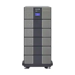
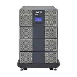
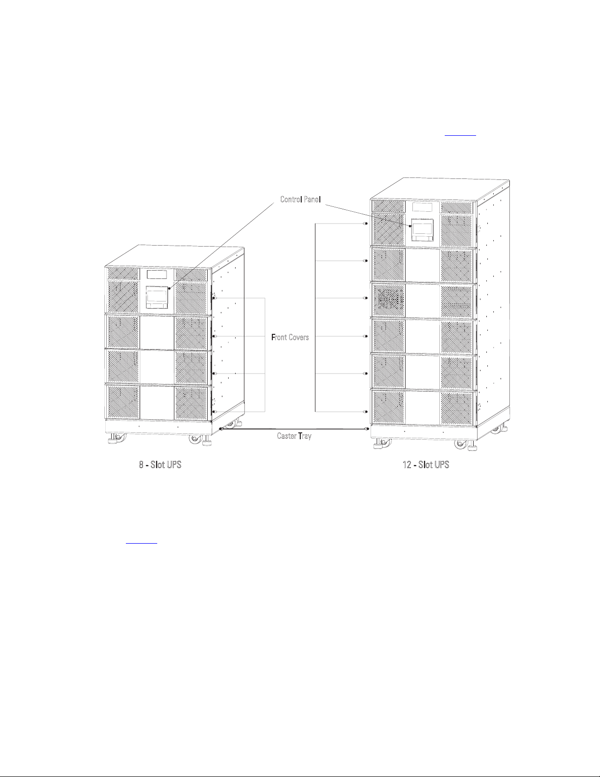
The Eaton 9PXM UPS is available in eight or twelve-slot cabinet sizes. The cabinet front has a control panel and
magnetic-latch front covers that provide access to the power modules and battery modules. Casters and
leveling feet are installed on a caster tray for a floor-mounted UPS installation (see Figure 1) .
Figure 1. Eight and Twelve-Slot Cabinets ( Front View)
Caster Tray
Control Panel
Front Covers
8 - Slot UPS 12 - Slot UPS
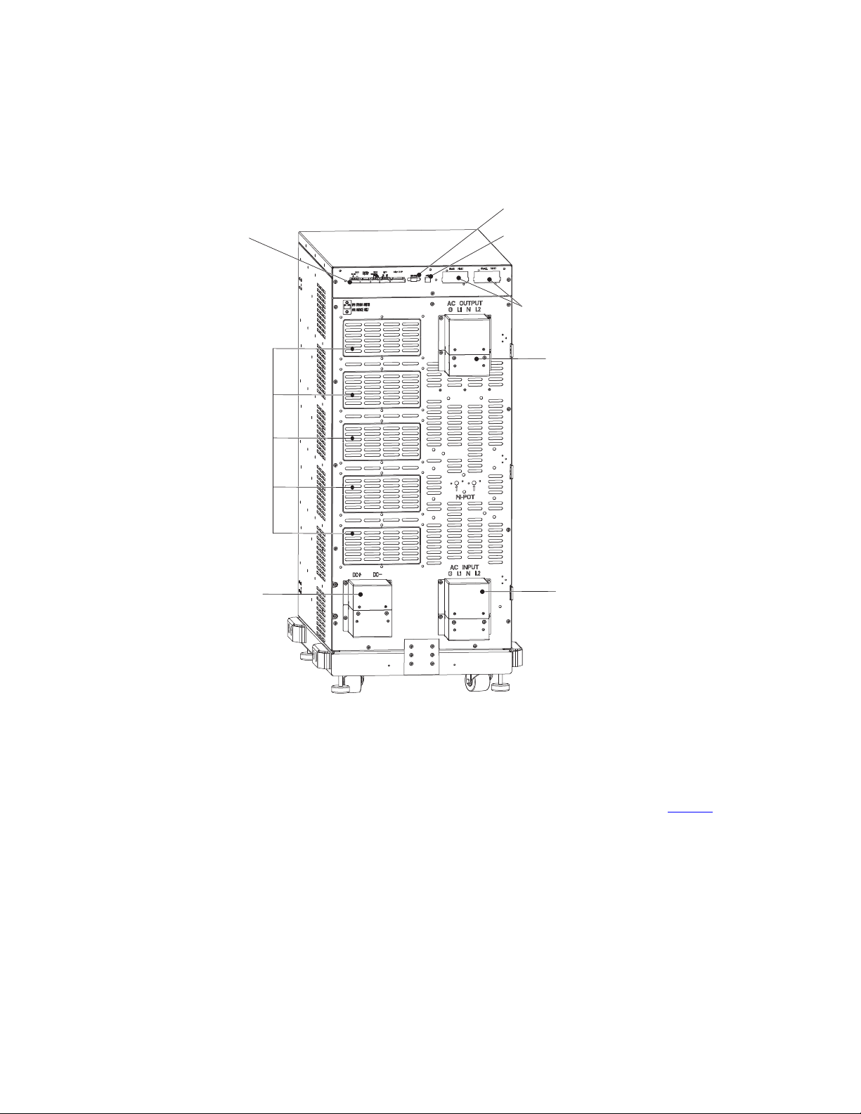
The rear UPS panel features power input and output connections with protective covers. Communication ports
provide input signals for maintenance bypass, remote power off, etc. DB-9, USB ports and communication
slots for network connectivity cards allow for remote monitoring of UPS operation. Slots for output receptacles
installed by Eaton are available by removable knockout panels depending on the user’s requirements (see
Figure 2 .
Physical Features
4 4–20kVA Users Guide P-164000669 4–20kVA Users Guide P-164000669—Rev 10
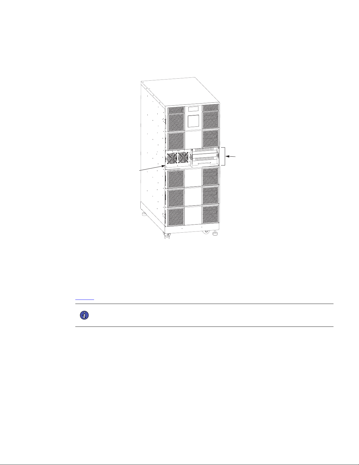
Figure 2. Twelve-Slot Rear View Access
AC Input Hardwired
Main AC Output Hardwired
EBM Input Connection
Communication Ports
Communication Card
Slots
DB-9 Port
USB Port
Knockout Recepticle Panels
(Twelve slot chassis shown.
Eight-slot similar)
Power Modules
UPS power modules (UPMs) are installed in the left hand slots of the UPS behind the front covers. Battery slots
consist of two battery modules each and can be used in both the right or left hand slots. (see Figure 3.
Physical Features
4–20kVA Users Guide P-164000669 4–20kVA Users Guide P-164000669—Rev 10 5
Figure 3. Power Modules and Battery Slots
Power Module
Battery Slot (typical)
(2 battery modules
per slot)
Twelve-slot Cabinet
Shown.
Battery Modules
As a UPS, the eight-slot 9PXM chassis can accommodate a maximum of seven two-battery slots and the
twelve-slot can contain up to eleven two-battery slots. Each two-battery slot contains two battery modules that
can be removed and installed separately from the battery slots in the chassis. A battery module supplies
60VDC with five 12V batteries, each 9PXM battery two-battery slot supplies 120VDC, with 10 batteries (see
Figure 4 ).
NOTE You must install one 9PXM battery string (Qty 2 battery modules) in the main UPS
chassis for every power module present or the UPS will sound a “Not Enough Battery”
alarm indication.
Physical Features
6 4–20kVA Users Guide P-164000669 4–20kVA Users Guide P-164000669—Rev 10
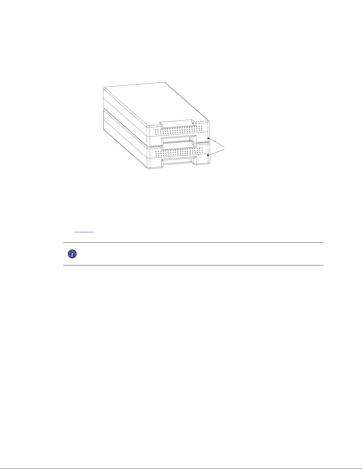
Figure 4. Battery Modules per Slot
Battery Modules (2)
Uninterruptible Power Modules (UPM)
The eight-slot 9PXM chassis can accommodate a maximum of four power modules and the twelve-slot can
contain up to six modules. Each 4kVA has a built in 5 amp battery charger and is cooled by two cooling fans.
(see Figure 5 ). One power module (UPM) is able to fully charge five 9PXM battery strings ( 10 9PXM battery
modules).
NOTE You must install one 9PXM battery string (2 battery modules) in the main UPS chassis
for every power module present or the UPS will sound an “Not Enough Battery” alarm
indication.
Figure 5. Uninterruptible Power Module
Super Charger Modules (Optional)
Physical Features
4–20kVA Users Guide P-164000669 4–20kVA Users Guide P-164000669—Rev 10 7
Super chargers have a built in 20 amp charger and are identical in appearance to power modules. They are
identified separately from each other by their labels. The UPS can contain a minimum of one (optional) super
charger while the “Connected”external battery module option can accommodate one in the lower left slot.
One super charger is able to fully charge (22) 9PXM battery strings or (44) individual battery modules.
Control Panel
The UPS control panel has a graphical LCD screen, light indicators and function buttons. It provides information
and control for the UPS, load status, events, measurements and settings. Refer to “7.1 Normal Operation” for
control panel description and operation. See Figure 6 .
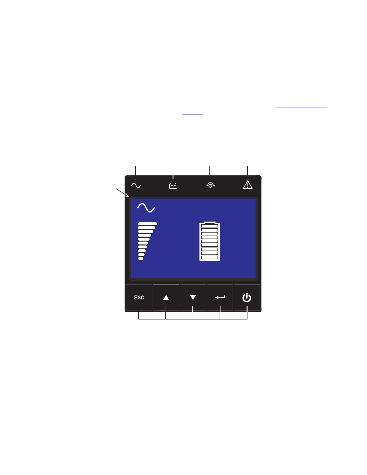
Figure 6. UPS Control Panel
Online mode
100%
19min
1EBM
100%
2.7kW
3.0kVA
Efficiency: 94 %
Indicator Lights
LCD
Screen
Power/Navigation
Buttons
Efficiency: 94%
100%
2.7kW
3.0kVA
100%
19min
1EBM
Online mode
Physical Features

8 4–20kVA Users Guide P-164000669 4–20kVA Users Guide P-164000669—Rev 10
Physical Features

4–20kVA Users Guide P-164000669 4–20kVA Users Guide P-164000669—Rev 10 9
CChhaapptteerr 22 IInnssttaallllaattiioonn SSeettuupp
22..11 PPrreeppaarriinngg ffoorr IInnssttaallllaattiioonn
This chapter explains how to set up and install the Eaton 9PXM eight and twelve-slot cabinets:
• Equipment Clearances
• Location Requirements
• UPS Setup
• Anchor Bracket Installation
• Rack-mount installation
22..22 EEqquuiippmmeenntt CClleeaarraanncceess
All cabinet sizes require the following clearances to allow for servicing and adequate ventilation:
• Sides: 15.2 cm (6")
• Top: 30.5 cm (12")
• Front: 91.5 cm (36")
Service Clearance
If flexible conduit connects the UPS to the service input and load distribution panels, you may be able to gain
access for servicing by moving the UPS. If this is the case, you must still leave 30.5 cm (12") clearance at the
back,15.2 cm (6") at the sides 91.5 cm (36") at the front of the UPS for ventilation.
NOTE Do not block the ventilation holes on each side and the back of the cabinet. Do NOT
attempt to move the cabinet with the power modules or battery modules installed.
External battery cabinets may be installed with bases tight against the UPS cabinet base and against each
other.
22..33 LLooccaattiioonn RReeqquuiirreemmeennttss
Install the Eaton 9PXM UPS as close as possible to the equipment or the load distribution panel it will protect.
If a separate external battery cabinet (EBM) is installed, the battery cabinets must be adjacent to the Eaton
9PXM UPS. If the batteries will be farther from the cabinet than the standard cables allow, contact your service
representative or your local distributor for assistance.
UPS cabinet dimensions are located in 10.7 Weights and Dimensions .
22..44 UUPPSS SSeettuupp
The Eaton 9PXM UPS eight and twelve-slot cabinets are shipped on a shipping pallet. Power modules and
battery modules are shipped in separate boxes on another pallet.
NOTE Installation for the eight-slot cabinets are identical to the twelve-slot cabinets. Twelve-
slot cabinets are shown in these set up instructions.
Do NOT attempt to move the cabinet with the power modules or battery modules installed.
To set up 8– or 12– slot cabinets:
10 4–20kVA Users Guide P-164000669 4–20kVA Users Guide P-164000669—Rev 10
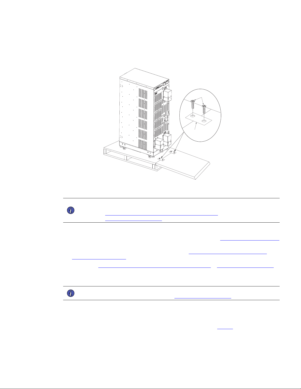
1. Move the UPS shipping pallet close to the desired location.
2. If installed, remove the straps and bracket bolts that attach the UPS to the pallet (see Figure 7 ) .
3. If you are rack-mounting the UPS, proceed to “ 2.6 Rack-Mount Installation” .
Figure 7. UPS on Shipping Pallet
Caster Cart
Leveling Feet
(4)
Bracket Bolts
(8)
4. Attach the supplied ramp to the pallet with the two brackets and four wood screws provided. ( See
Figure 8).
5. Retract the leveling feet by turning them clockwise then carefully roll the cabinet down the ramp to its
intended operating location ( See Figure 8) .
UPS Setup
4–20kVA Users Guide P-164000669 4–20kVA Users Guide P-164000669—Rev 10 11
Figure 8. Moving the UPS from the Pallet
Pallet Rear
Pallet Front
Ramp
Ramp
Pallet
Screws
Bracket
NOTE For ease of installation, determine if you have sufficient clearance at the rear of the UPS
to complete the electrical connections before securing the UPS in its final position (see
3.1 Installation of the UPS with an External Bypass Switch or
4.2 UPS Electrical Installation”.
6. Level the cabinet at its operating location by extending the four leveling feet.
7. If you are installing the floor anchors and they are not already installed, see “2.5 Anchor Bracket Installation
“ in the next section to install the floor anchor brackets.
8. If you are installing an external battery cabinet, continue to “5.2 Standard Battery Cabinet Installation or
5.1 Battery Cabinet Options” .
9. Continue to “3.1 Installation of the UPS with an External Bypass Switch or 4.2 UPS Electrical Installation “.
as applicable.
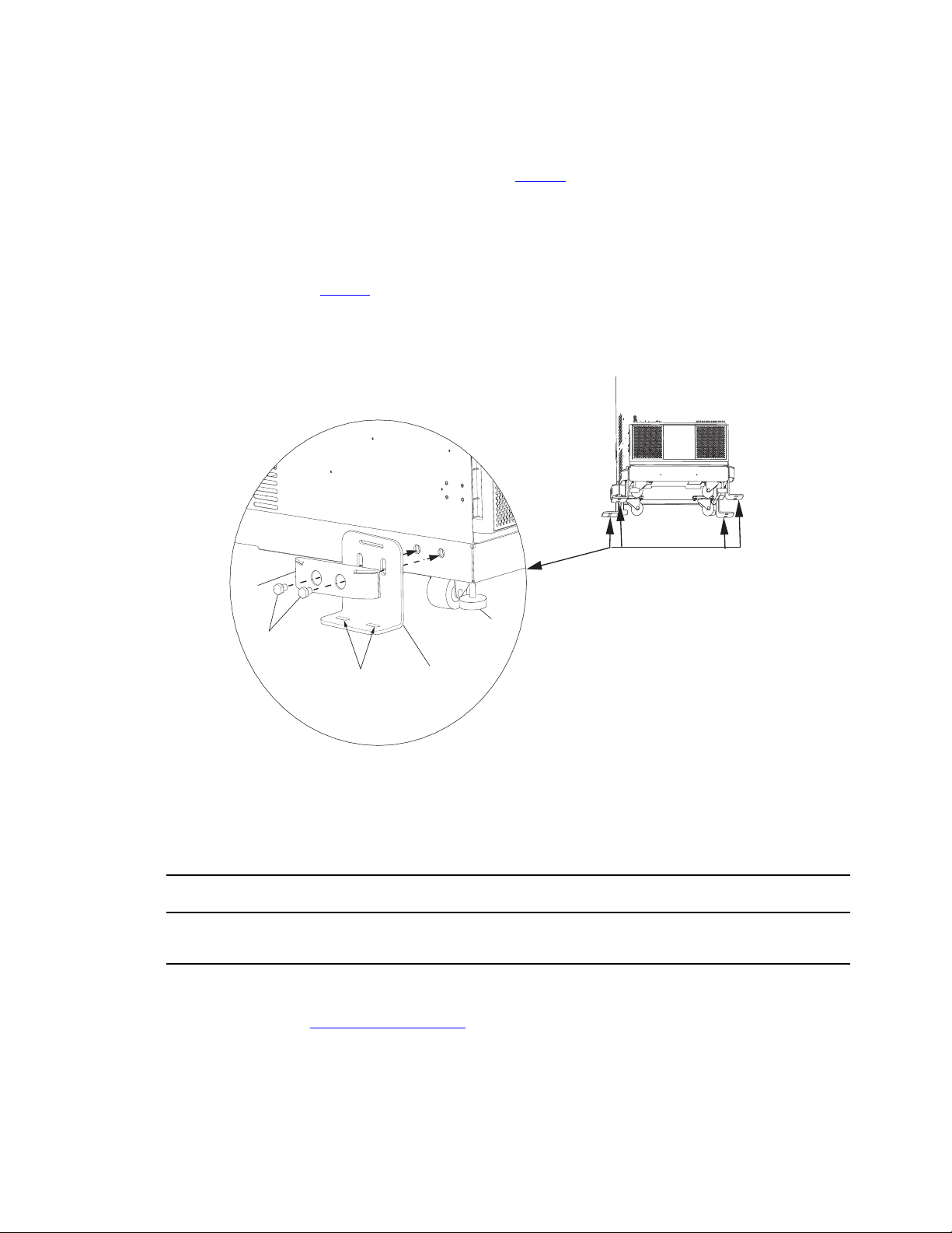
22..55 AAnncchhoorr BBrraacckkeett IInnssttaallllaattiioonn
NOTE For ease of installation, complete the rear electrical connections before securing the
anchor brackets to the floor. See or 4.2 UPS Electrical Installation .
The Eaton 9PXM UPS cabinet is shipped with four anchor (stabilizer) brackets (Kit P-157002300). These
brackets must be attached to the floor. Under all module-loading conditions, they act as a protective stop to
prevent the cabinet from falling forward if it is unintentionally pushed.
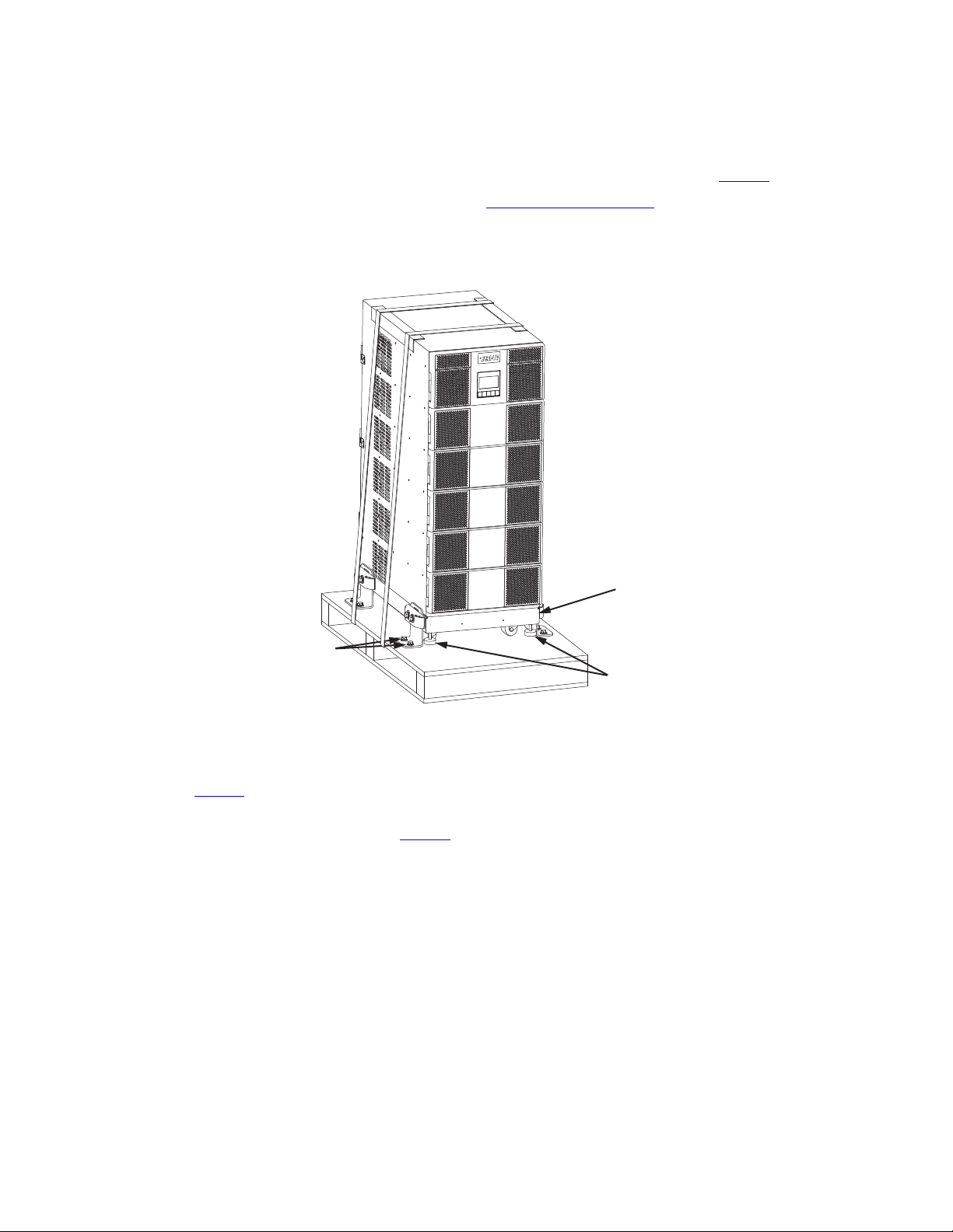
Each bracket has holes that enable it to be attached by screws to the floor (see Figure 9 ). The anchor brackets
are attached to the cabinet base itself.
To install the stabilizer brackets:
Anchor Bracket Installation
12 4–20kVA Users Guide P-164000669 4–20kVA Users Guide P-164000669—Rev 10
1. Select the location for the brackets at the floor intersection beside the intended cabinet location.
2. Attach the brackets to the cabinet base as shown in Figure 9 .
3. Roll the UPS cabinet to its intended location. Position the rear section of the cabinet base under the open
ends of the stabilizer brackets as far as the cabinet will go.
4. Turn all four leveling feet counter-clockwise until the cabinet is level.
5. Using the proper type of customer-supplied screws for the intended mounting surface, attach each
bracket as shown in Figure 9 . All screws must be properly driven into the structural material.
Figure 9. Floor Anchor Bracket Installation
Floor Anchor
Bracket
Floor Bolt
Slots
Mount Bolts
Spacer
Leveling
Foot
*Installation to be updated
(spacers/bolts)
22..66 RRaacckk--MMoouunntt IInnssttaallllaattiioonn
The 12-slot UPS weighs 93 kg (204 lb) with the caster cart. Install the cabinet in the rack before installing power
and battery modules and before making connections to the intended power source.
The Eaton 9PXM UPS and the battery cabinet are very heavy with power modules and two battery modules per
slot installed. If installed, before moving the cabinets, remove the power modules and battery two battery
modules per slot (see “9.1 Routine Maintenance ” ).
Rack-Mount Installation
4–20kVA Users Guide P-164000669 4–20kVA Users Guide P-164000669—Rev 10 13
NOTE 1 The UPS cabinets may be installed in an EIA-standard 48.3 cm (19") equipment rack. An
optional rack-mounting kit (P-157002204), containing brackets and required hardware, is
available.
NOTE 2 This procedure is also applicable to the P-103002494 12-slot external battery module
(EBM).
Use the following mounting procedures to install the UPS cabinet into the equipment rack:
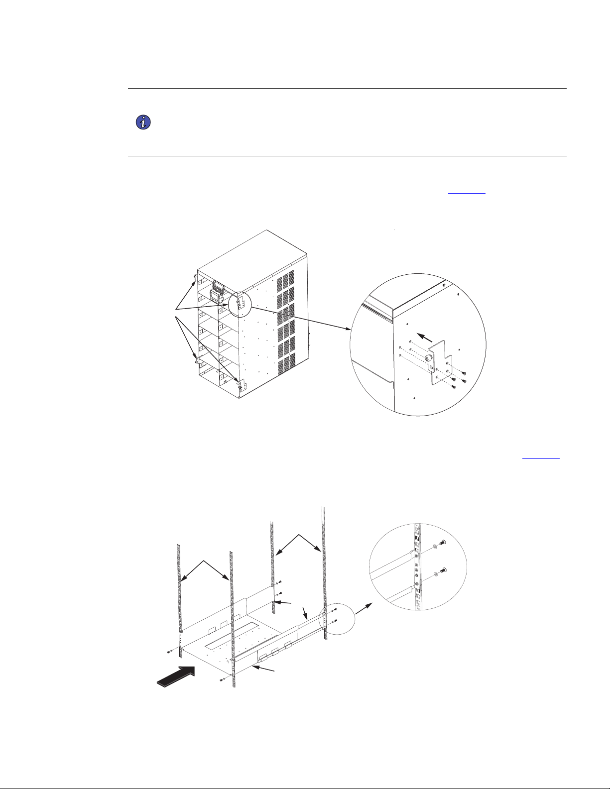
1. Install rack-mount ears ( two per side ) on each side of the UPS cabinet ( See Figure 10).
Figure 10. Rack-Mount Ear installation
Rack-Mount
Ears
2. Select the proper holes in the front vertical rack rails that position the rack tray at the bottom in the rack
and extend the back rails to align with the rear holes. Secure with the screws and washers (see Figure 11
).
Figure 11. Rack Tray Location
Rail Tray
Screw
Washer
Rail Backs
UPS Rack Rails
UPS Rack Rails
(Front)
Rack-Mount Installation
14 4–20kVA Users Guide P-164000669 4–20kVA Users Guide P-164000669—Rev 10
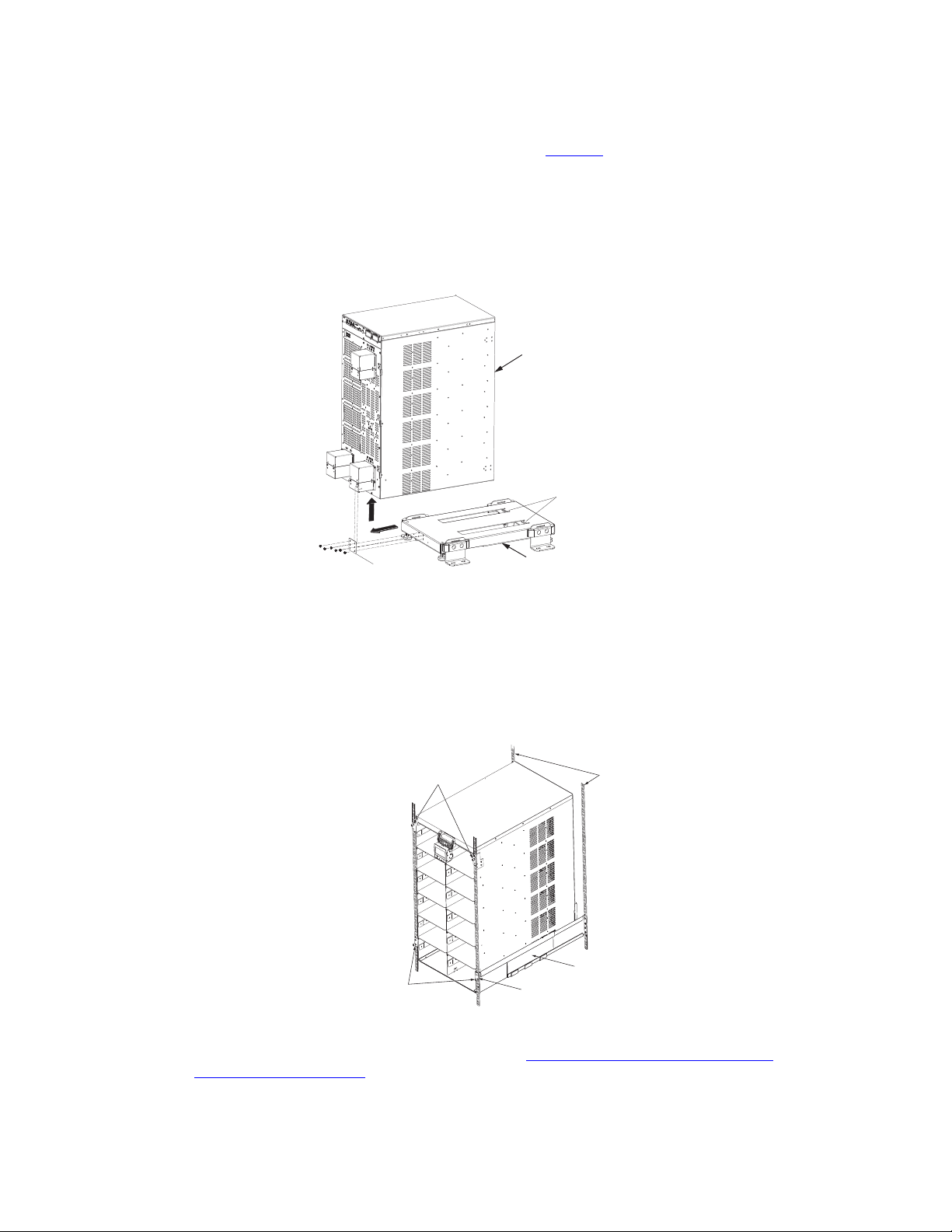
3. Remove the cabinet from the castor cart as follows ( see Figure 12 ).
a. Lower the leveling feet to stabilize the castor cart.
b. Remove the rear bracket and screws.
c. Using two people, slide the cabinet backwards to disengage it from the slot tabs.
Figure 12. Remove Cabinet from Castor Tray
Slot Tabs
Rear Bracket
Note: Attach appropriate
lifting device and use at
least two people to lift the
UPS cabinet
Caster Tray
UPS Cabinet
4. Carefully slide the UPS from the caster tray onto the rail tray in the equipment rack until the rack-mount
ears of the cabinet are almost flush with the front vertical rails of the rack. Install metal clip nuts in the rack
in line with the upper mounting brackets. Install the provided screws.
5. Install the provided screws into the lower rack mount ears to the threaded holes in the rail tray.
Figure 13. Securing the UPS in the Rack
Screws
Screws
Rack Mount
Ears
Rail Tray
Equipment Rack
Rails
6. If you are installing an optional EBM cabinet refer to, “5.2 Standard Battery Cabinet Installation” or “
5.1 Battery Cabinet Options”.
Rack-Mount Installation
4–20kVA Users Guide P-164000669 4–20kVA Users Guide P-164000669—Rev 10 15
CChhaapptteerr 33 UUPPSS WWiitthh EExxtteerrnnaall BByyppaassss IInnssttaallllaattiioonn
33..11 IInnssttaallllaattiioonn ooff tthhee UUPPSS wwiitthh aann EExxtteerrnnaall BByyppaassss SSwwiittcchh
The Eaton 9PXM UPS input power is hardwired through a conduit to either a main power source circuit breaker or to an optional
bypass switch. It is recommended that you install an Eaton® Bypass Power Module (BPM) to enable power transfer during
maintenance or UPS downtime.
Risk of electrical shock. Only qualified service personnel (such as a licensed electrician) should perform the
electrical installation in this section.
NOTE For installation and configuration of the Eaton bypass switch refer to the manual “Eaton
Bypass Power Module (BPM) User’s Guide P-164000628” supplied with the switch or
on the Eaton website https://www.eaton.com/9PXM .
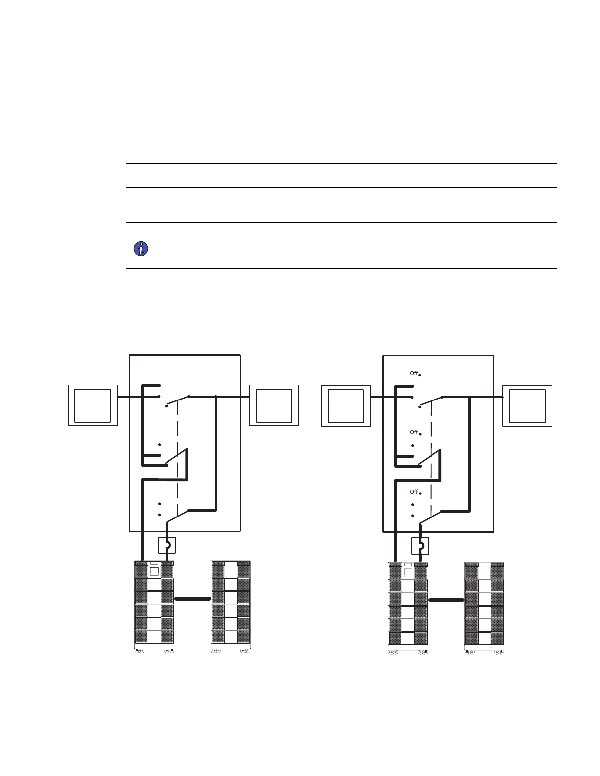
If a bypass switch is used, both UPS input and UPS output must be hardwired through separate conduits to the
bypass switch, as shown in Figure 14.
Figure 14. Typical Installation with a Bypass Switch
External Bypass Switch
External Bypass Switch
BPM Design BPE Design
MBB Option
Service
Line
Service
Line
UPS
UPS
Service
Line
UPS
User-Supplied
(if required)
Building
Service
Panel
Load
Distribution
Panel
(optional)
External Battery
Module
Service
Line
Service
Line
UPS
UPS
Service
Line
UPS
User-Supplied
(if required)
Building
Service
Panel
Load
Distribution
Panel
(optional)
External Battery
Module

16 4–20kVA Users Guide P-164000669 4–20kVA Users Guide P-164000669—Rev 10
33..22 CCiirrccuuiitt BBrreeaakkeerr IInnppuutt RRaattiinnggss
Table 1. Recommended Breaker Sizes
UPS Capacity Input Circuit breaker Rating 75°C Copper Wire Size
4kVA 25A
5.3 mm2 (10 AWG)
8kVA 50A
8.4 mm2 (8 AWG)
12kVA 80A
21.2 mm2 (4 AWG)
16kVA 100A
33.6 mm2 (2 AWG)
20kVA 125A
42.1 mm2 (1 AWG)
NOTE 1 If you are installing an optional super charger module in the UPS, then it is the same as a
power module with the proper input circuit breaker sizes and ratings.
NOTE 2 To accommodate the feature of easy system expandability, it is recommended that
initial installation of the Eaton 9PXM UPS contains wiring to support the maximum
capacity of the UPS cabinet of 20kVA for 12-slot and 16-kVA for 8-slot cabinets.
NOTE 3 The 9PXM is limited to an input current of 125A. In the event an additional charging
module has been employed in conjunction with the maximum allotted number of power
modules, no additional input ampacity will be required.
See Table 2 for recommended conductor sizes to wire the input circuit breakers.
Table 2. Recommended Wire Sizes
Input Breaker Size 75° Copper Wire Size Conductor Screw Tourqe
25A
5.3 mm2 (10 AWG) 4.0 Nm (35 lb in)
50A
8.4 mm2 (8 AWG) 4.5 Nm (40 lb in)
80A
21.2 mm2 (4 AWG) 5.1 Nm (45 lb in)
100A
33.6 mm2 (2 AWG) 6.6 Nm (50 lb in)
125A
42.1 mm2 (1 AWG) 6.6 Nm (50 lb in)
!
IMPORTANT
• Table 2 lists the mm2 and AWG wire size for each circuit breaker size shown on the wiring diagrams. The
minimum recommended circuit breaker sizes for each model and voltage application are listed on the
wiring diagrams.
• Conductor sizes shall be no smaller than the 75°C wire size based on the ampacities given in Table 310.15
(B)(16) of the National Electrical Code® (NEC®), ANSI/NFPA 70-2017, and article 220. All circuit
conductors, including the neutral conductor, must be the same size (ampacity) wire. Code may require a
larger AWG size than shown in this table because of temperature, number of conductors in the conduit, or
long service runs. Follow local code requirements.
Circuit Breaker Input Ratings
4–20kVA Users Guide P-164000669 4–20kVA Users Guide P-164000669—Rev 10 17
33..33 UUPPSS CCoonnnneeccttiioonnss
NOTE For installation and configuration of the Eaton bypass switch refer to the manual “Eaton
Bypass Power Module (BPM) User’s Guide P-164000628” supplied with the switch or
on the Eaton website.
UPS Connections
NOTE 1 Refer to “ 3.2 Circuit Breaker Input Ratings” for breaker, terminal block, and wire sizing.
NOTE 2 Connection Diagrams can be found on Figure 17 and on Figure 18 .
To prevent electrical shock or damage to the equipment, verify that the Eaton 9PXM UPS is OFF before you
remove the terminal covers. The circuit breaker or disconnect switch must also be OFF at the AC input service
panel.
To install the UPS with an external bypass switch:
1. Mount the bypass switch within sight of the UPS. If you do not have an Eaton bypass switch or the fuse
box or panel is out of sight, you must install a separate disconnect switch next to the UPS.
2. The bypass switch should be mounted securely to a sturdy surface. You may need to turn the cabinet 90
degrees (on its side) to enable operator access to the switch handle.
3. Remove the six screws on the bypass switch wiring cover and remove the cover. Remove any packing
material inside the bypass switch.
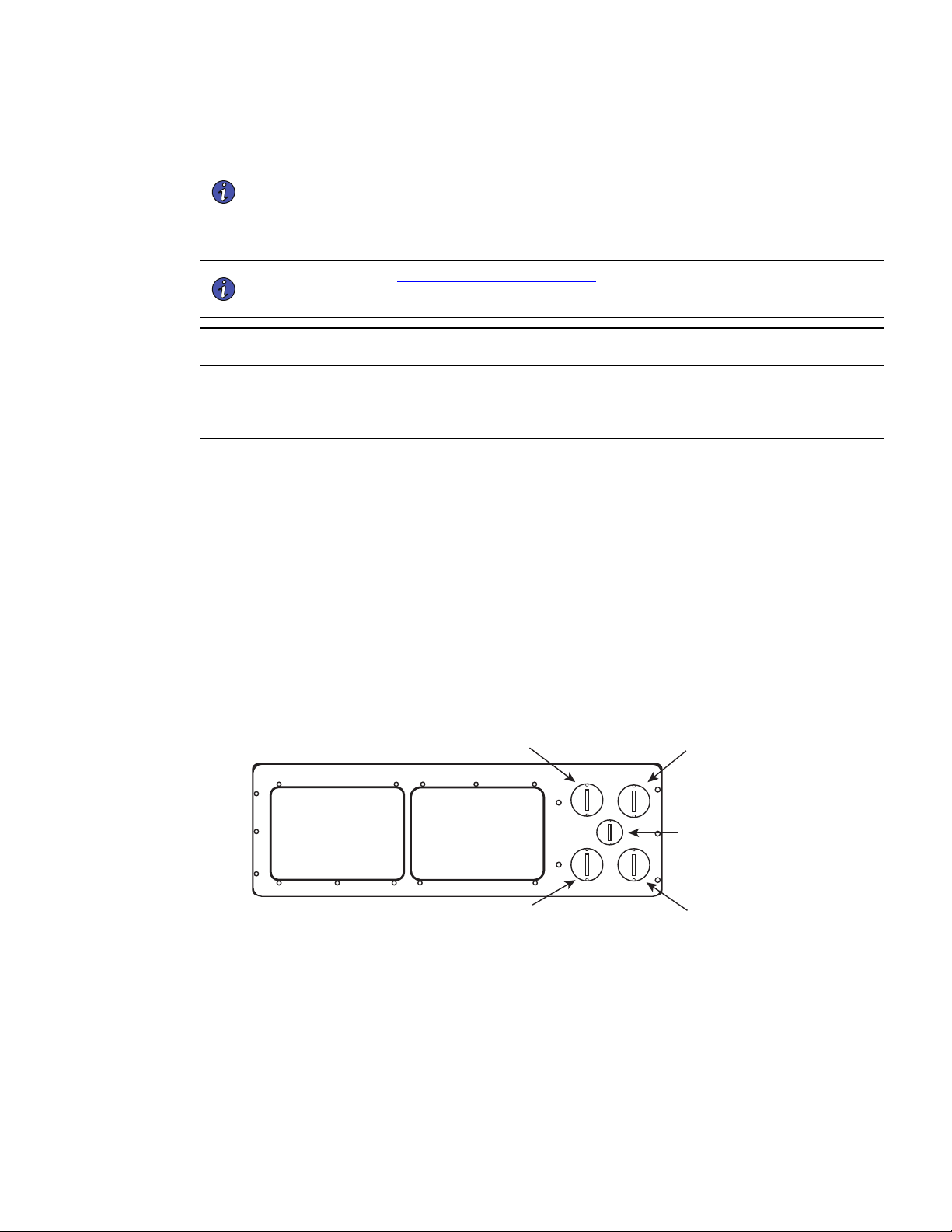
4. Remove the knockouts in the bottom of the BPM as needed for wiring. See Figure 15
Figure 15. BPM Bypass Bottom
From UPS Output To UPS Input
BPM Signal Wire
To Load
From Line
UPS Connections
18 4–20kVA Users Guide P-164000669 4–20kVA Users Guide P-164000669—Rev 10
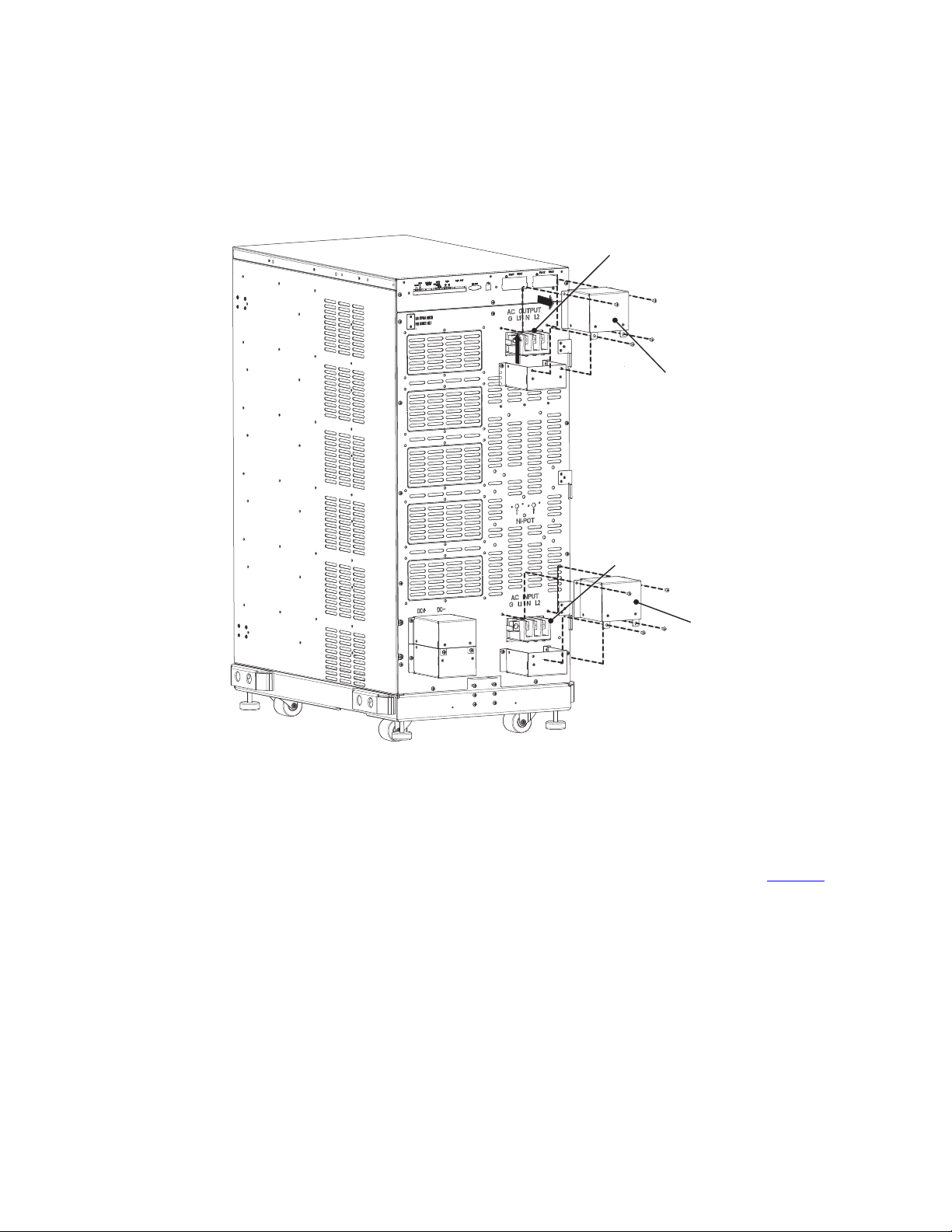
Figure 16. UPS AC Power Terminal Access
Terminal Cover
AC Output Terminals
AC Input Terminals
Terminal Cover
5. At the AC Input terminal, make sure to wire the UPS for the proper input voltage as shown in Figure 17 .
Split-phase power modules provide a 2-phase output which can be configured as output voltages: 110/110
for 220, 120/120 for 240, 120/120 for 208, or 127/127 for 220 Vac, as selected through the front panel
display.
UPS Connections
4–20kVA Users Guide P-164000669 4–20kVA Users Guide P-164000669—Rev 10 19
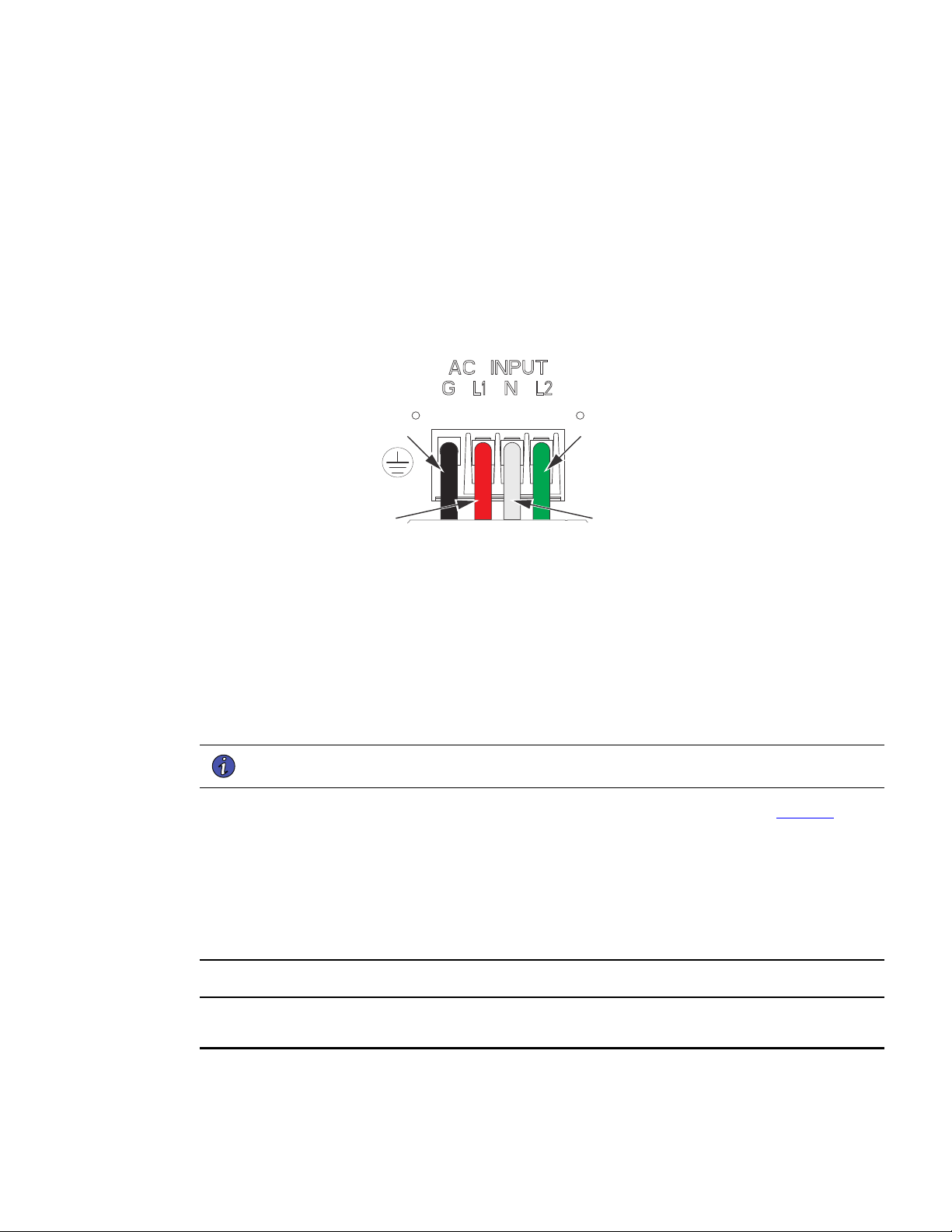
Figure 17. Split-Phase Power Modules
Split-Phase Power Modules
(3-wire plus ground input) (2 PEN)
110/220, 120/208, 120/240, 127/220 Vac
L2
N
GND
L1
NOTE UPS output circuits must be installed in separate conduit systems and not shared with
other electrical circuits.
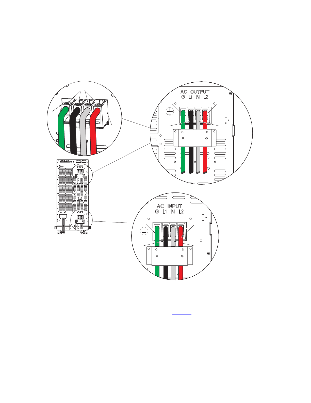
6. Make the UPS input and output connections to the terminal blocks on the rear panel (see Figure 18 ):
a. Insert the L1, N and L2 cable ends into the applicable terminal slots on the terminal block.
b. Insert the G (GND) cable end into the ground lug on the rear panel.
c. Secure the cables by screwing down the lug screws.
d. Torque the screws holding all input and output power conductors to the values specified in .
e. Reinstall the AC and DC terminal covers.
To reduce the possibility of electric shock all AC and DC terminal covers must be installed on the back of the
UPS prior to any battery or power modules being inserted into the UPS.
UPS Connections
20 4–20kVA Users Guide P-164000669 4–20kVA Users Guide P-164000669—Rev 10
Figure 18. UPS Input and Output Terminals
L2
N
GND
L1
AC Input
Connections
AC Output
Connections
N
L2
GND
L1
L1
AC Terminal
Blocks
Lug Screws
Terminal
Block
Ground
Lug
7. Route the power cables to the BPM and install conduit adapters to the BPM bottom plate.
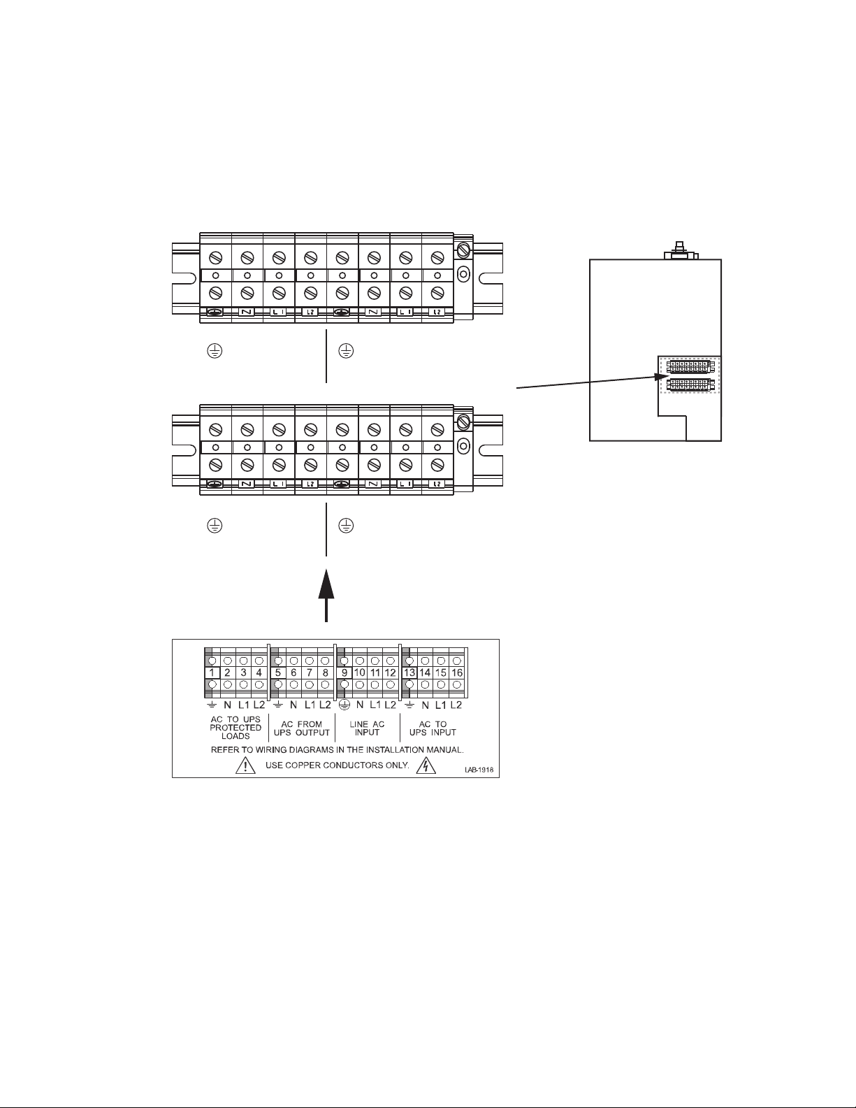
8. Use the label on the top of the BPM access cover and Figure 19, and make the connections to the BPM
terminal blocks. Tighten all connections as specified in . Use copper wire that is the appropriate size for the
current draw.
UPS Connections
4–20kVA Users Guide P-164000669 4–20kVA Users Guide P-164000669—Rev 10 21
Figure 19. Bypass Switch Wiring Label and Terminal Blocks
1 2 3 4 5 6 7 8
1 2 3 4
5
6
7
8
BPE Terminal Block
AC TO
UPS INPUT
L2 N L1 L2 N L1
AC TO LOADS
CABLES FROM UPS AND AC
INPUT/OUTPUT THROUGH BPM
BOTTOM ACESS PLATE
AC FROM
UPS OUTPUT
L2 N L1 L2 N L1
Upper BPM Terminal Block
Lower BPM Terminal Block
AC LINE INPUT
9. After installing bypass switch wiring, torque the screws holding all input and output power conductors to
the values specified.
UPS Connections
22 4–20kVA Users Guide P-164000669 4–20kVA Users Guide P-164000669—Rev 10
33..44 BBPPMM SSiiggnnaall IInnppuutt WWiirree RRoouuttiinngg
The auxiliary contacts must be wired to the BPM from the UPS for proper functionality. These auxiliary contacts
signal the UPS to go to Internal Bypass mode to provide a synchronized transfer. Failure to wire the auxiliary
contacts can be dangerous and result in system failure.
If the UPS is in standby mode and the bypass auxiliary contact is activated, the UPS output will become
energized.
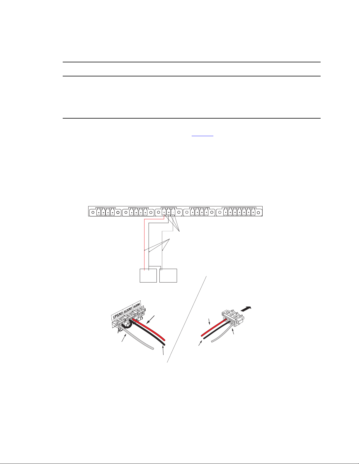
1. Route the maintenance bypass signal wires in a conduit from the bypass module to the communication
signal terminal (CN13) on the rear of the UPS ( See Figure 20 ). For conduit requirements consult your local
electrical code.
2. Place the signal wires through the proper conduit or grommet to the terminal block in the BPM.
Figure 20. UPS Input Control Signal Wiring for Maintenance Bypass
AUX NO
CONTACT
NO
CONTACT
ON UPS
(white wire)
BYPASS
NEUTRAL
(black wire)
FORCED
BYPASS IN
(red wire)
External CAN to EBM
(CN4)
Maintenance Bypass
(CN13)
EPO
(CN7)
3 2 14 3 2 1 4 3 2 1 4 3 2 1 7 6 5 4 3 2 1
Input signal
wires
ROO and On Generator
(CN6)
Building Input
(CN5)
Bypass Module
Terminal
BYPASS
NEUTRAL
(black wire)
FORCED
BYPASS IN
(red wire)
FORCED
BYPASS IN
(red wire)
BYPASS
NEUTRAL
(black wire)
Attach supplied
wire connectors to input wires
and plug into UPS
BPM Signal
Terminals
ON UPS
(white wire)
ON UPS
(white wire)
(Install conduit
over signal wires)
UPS Signal
Terminals
BPM Signal Input Wire Routing
4–20kVA Users Guide P-164000669 4–20kVA Users Guide P-164000669—Rev 10 23
NOTE Do not strain relieve EPO or external bypass wiring with the same cable tie used for
Generator “On” wires.
EPO and external bypass circuits are safety extra low voltage circuit. This circuit must be isolated from any
hazardous voltage circuits by reinforced insulation.
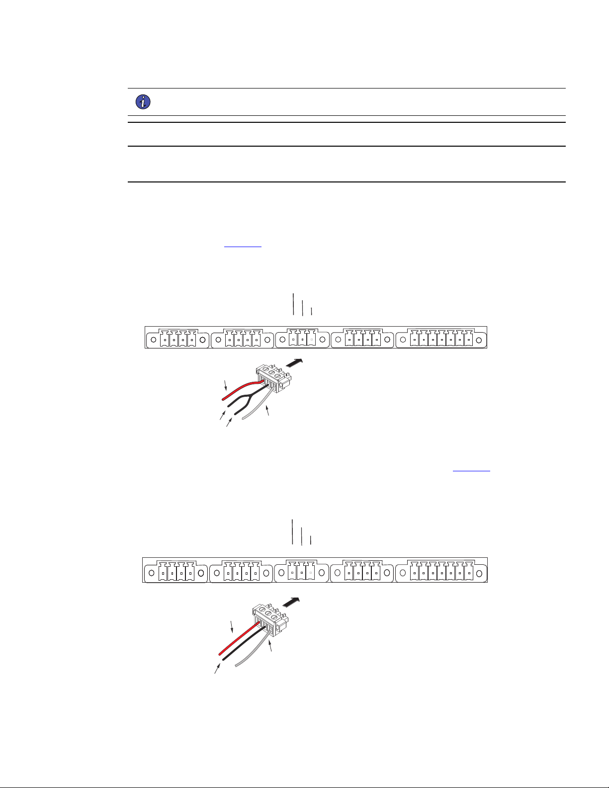
3. Attach the supplied cable connectors to the ends of the input wires.
4. For BPE connections as shown in :
a. Connect up the 4 wires from the BPE to the 9PXM per the attached drawing and using the 3 pin
connector (see Figure 21 ).
Figure 21. BPE to UPS Connector
3 2 14 3 2 1 4 3 2 1 4 3 2 1 7 6 5 4 3 2 1
Force Bypass
Common
On UPS
FORCED
BYPASS IN
(red wire)
BYPASS
NEUTRAL
(black wire)
ON UPS
(white wire)
b. Install the 3 pin connector into the 9PXM UPS BPM CN13 connector (see Figure 22 ).
Figure 22. Three-Pin BPM to UPS Connector
FORCED
BYPASS IN
(red wire)
BYPASS
NEUTRAL
(black wire)
ON UPS
(white wire)
3 2 14 3 2 1 4 3 2 1 4 3 2 1 7 6 5 4 3 2 1
Force Bypass
Common
On UPS
BPM Signal Input Wire Routing
24 4–20kVA Users Guide P-164000669 4–20kVA Users Guide P-164000669—Rev 10
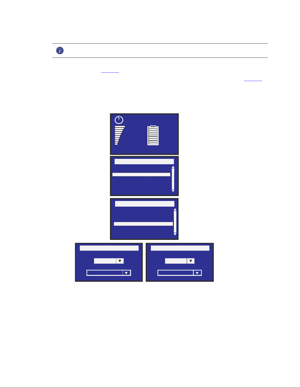
NOTE Make a note to enable Forced and Maintenance Bypass per the following step when
installation is complete and power available.
c. Navigate the 9PXM LCD to the forced and maintain bypass settings Input signals menu in the 9PXM
user guide (see Figure 23 ).
d. Set both Forced Bypass and Maintain Bypass settings to Enabled and Normally open (see Figure 23 ).
Figure 23. Forced and Maintenance Bypass Screens
Force Bypass
Dry contact setting
Enabled
Polarity
Normally open
Menu
Measurements
Control
Settings
Event Log
Fault Log
Identification
Register product
Settings
In/Out settings
Local settings
On/Off settings
Battery settings
Input Signals
Comm Settings
User Password Enable
User Password setting
Maintain Bypass
Dry contact setting
Enabled
Polarity
Normally open
Efficiency: 94%
0%
0.0kW
0.0kVA
100%
19min
1EBM
Load not powered
5. Install the supplied wiring connectors to the UPS input control signal wires and connect to the terminals as
shown in or .
6. When all connections have been made and checked, reinstall the bypass switch front cover using the
original screws.
7. If floor anchor brackets were installed and not secured, install the floor bolts.
BPM Signal Input Wire Routing

4–20kVA Users Guide P-164000669 4–20kVA Users Guide P-164000669—Rev 10 25
8. After electrical installation is complete, you must also set the output settings menu for the required output
voltage as shown in the wiring configuration drawings (See 3.5 System Wiring Diagrams ).
33..55 SSyysstteemm WWiirriinngg DDiiaaggrraammss
SSyysstteemm WWiirriinngg DDiiaaggrraamm
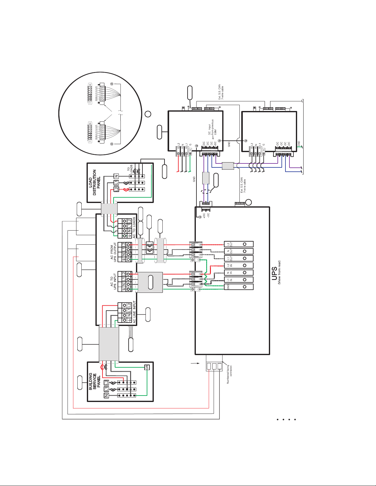
Refer to the system wiring diagram for correct installation The following notes are referenced by their number
in the UPS with external bypass wiring diagram (see Figure 24 and Figure 25 ).
NOTE 1 The customer must provide input overcurrent protection. See NEC Section 240-21
or local requirements. See 3.2 Circuit Breaker Input Ratings for circuit breaker ratings to
size the protection device according to local code requirements.
NOTE 2 The UPS bypass switch must be installed within sight of the UPS. To properly install,
complete the voltage and phase check procedure in “ 6.1 UPS Startup ”. The wires
coming from the side of the switch must be connected as described in .
NOTE 3 The customer must size the AC circuit conductors. All AC circuit conductors,
including the neutral conductor, must be the same size ( ampacity ), have the same
rating (75°C) copper wire, and be sized according to the input circuit breaker. See
Table 2 . The UPS input and output conductors must be run through separate conduits.
NOTE 4 The customer must provide output overcurrent protection. See NEC Section 240-21
or local requirements. See Table 1 for maximum output overcurrent protection device
ratings.
NOTE 5 See “2.1 Preparing for Installation ” for installation and service clearances before
installing the UPS. Use flexible conduit on the UPS or the external battery cabinet if
either must be moved.
NOTE 6 External UPS battery cabinets are optional. See “
5.2 Standard Battery Cabinet Installation or 5.1 Battery Cabinet Options ” for installation
instructions.
NOTE 7 UPS output circuits shall be installed in dedicated conduit systems and not shared with
other electrical circuits.
NOTE 8 Use only Eaton-supplied power cables between the UPS and EBM(s) (PN:P-103003231).
NOTE 9 CN3 and CN4 CAN cables ground separately to each cabinet chassis.
System Wiring Diagrams
26 4–20kVA Users Guide P-164000669 4–20kVA Users Guide P-164000669—Rev 10
Figure 24. Wiring Diagram- UPS with External Bypass Switch (BPM) (L1, L2, N)
T
CN13
3
2
1
2
2
3 7
4
5
3
1
CN3
CN4
CN6
CN6
OUTPUT POWER
BUS BAR
AC OUTPUT
AC INPUT
5
EXTERNAL BPM
(Maintenance Bypass)
3
2 3
UPS INPUT
SIGNALS
6
7
AC INPUT
TO EBM 1
AC INPUT
TO EBM 2
TO NEXT EBM
(If installed)
DC
INPUT
EBM 1
}
EBM 2
CN3
CN4
8
9
7 6 5 4 3 2 1*
7 6 5 4 3 2 1
UPS
CN4
EBM
CN4
Supplied
Connectors
*Pin numbering
is right-to-left
Input Signal connections
(Typical)
A
A
G
N1L 2L
G
L2
L1
N
110/220 Input, 110/220 Output
120/208 Input, 120/208 Output
120/240 Input, 120/240 Output
127/220 Input, 127/220 Output
Force Bypass Red Wire
Common Black Wire
On UPS White Wire
AUX
CONTACT
WHITE WIRE
COMBINE BLACK WIRES
RED WIRE
NO
NO
CONTACT
6
7
8
6
8
7
5
1 2 3 4 1 2 3 4
System Wiring Diagrams
4–20kVA Users Guide P-164000669 4–20kVA Users Guide P-164000669—Rev 10 27
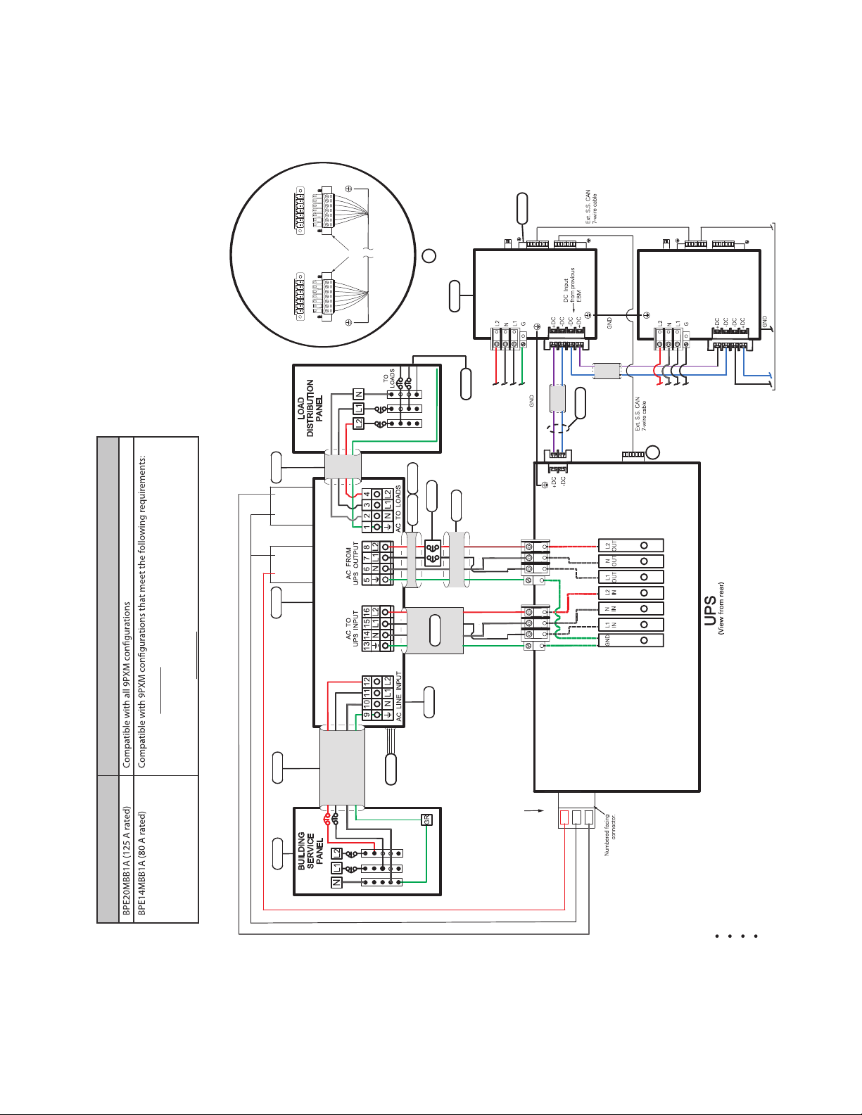
Figure 25. Wiring Diagram- UPS with External Bypass Switch (BPE) (L1, L2, N)
AUX
CONTACT
WHITE WIRE
COMBINE BLACK WIRES
RED WIRE
NO
CN13
3
2
1
2
2
3 7
4
5
3
1
CN3
CN4
CN6
CN6
110/220 Input, 110/220 Output
120/208 Input, 120/208 Output
120/240 Input, 120/240 Output
127/220 Input, 127/220 Output
OUTPUT POWER
BUS BAR
AC OUTPUT
AC INPUT
EXTERNAL BPE
MBB Option
(Maintenance Bypass)
3
2
3
UPS INPUT
SIGNALS
6
7
AC INPUT
TO EBM 1
AC INPUT
TO EBM 2
TO NEXT EBM
(If installed)
DC
INPUT
EBM 1
}
EBM 2
CN3
CN4
8
9
7 6 5 4 3 2 1*
7 6 5 4 3 2 1
UPS
CN4
EBM
CN4
Supplied
Connectors
*Pin numbering
is right-to-left
Input Signal connections
(Typical)
A
A
G
L2L1 N
G
L2
L1
N
NO
CONTACT
Force Bypass Red Wire
Common Black Wire
On UPS White Wire
2. (3) UPS’s (9PXMSPPM) split-phase power modules and
(1) Supercharger (9PXMCHGR) or less installed in a 9PXM UPS*.
Legacy Bypass 9PXM Compatibility
1. (4) UPS’s (9PXMSPPM) split-phase power modules or less
installed in a 9PXM UPS*.
*Since BPE14MBB1A is rated for 80A you cannot install more than 80A of 9PXMSPPM split-phase power modules and
9PXMCHGR battery modules into a 9PXM UPS. Each 9PXMPPM split-phase module and 9PXMCHGR battery charger
module is rated at 20A maximum current.
System Wiring Diagrams
28 4–20kVA Users Guide P-164000669 4–20kVA Users Guide P-164000669—Rev 10
33..66 BByyppaassss OOvveerrvviieeww
The BPM has three operating positions (see Table 3 ). Consider both the operating state of the UPS and the
BPM when protecting your critical loads.
Failure to understand the correct bypass sequence and position may cause the critical load to be dropped.
Damage to the power modules or the Bypass switch can occur.
• If the UPS remains in Bypass Mode and incoming AC power is lost, the load is automatically dropped. The
UPS must be in Normal Mode to provide battery backup power.
• In the UPS or LINE position, AC input power is still connected to the input terminals inside the UPS.
• If the UPS is in the standby mode and the bypass switch is in the LINE or UPS positions pressing
the red bypass switch interlock button will energize the UPS output.
• Do not attempt to push the red interlock button or attempt to move the bypass switch handle if the
UPS is operating on battery power.
• If you have any questions or problems with the bypass operation, call the Help Desk (see , “
11.2 Service and Support ” ).
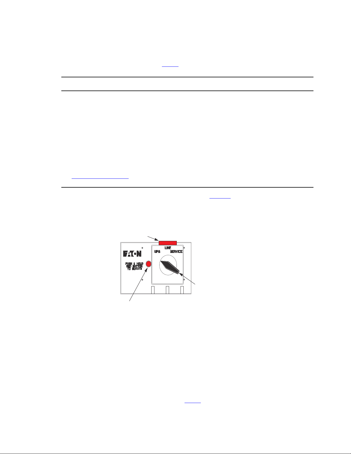
The BPM consists of a load position handle and a red button (see Figure 26 ).
Figure 26. Bypass Switch Positions
LOTO Bar (red)
Interlock Button (red)
Bypass switch
handle
The red button:
• Sends an electrical signal to the UPS to switch to the Bypass Mode (if it is not already operating in that
mode ).
• Operates a mechanical interlock, to prevent the switch from being turned without first signaling the UPS.
You must press the red button before you can turn the load position handle.
When the red button is pressed, the UPS front panel displays “Bypass Mode.” To move the MBP switch
handle from one position to another, the red button must be pressed WHILE the handle is being rotated.
Otherwise, the switch will be damaged.
The bypass switch has three positions as described in Table 3 .
Bypass Overview

4–20kVA Users Guide P-164000669 4–20kVA Users Guide P-164000669—Rev 10 29
NOTE In the UPS or LINE position, AC input power is still connected to the input terminals
inside the UPS.
Table 3. Bypass Switch Positions
Switch Position Description
LINE When the switch is in the LINE position, utility power is directly connected to the
critical load and the output of the UPS is disconnected. In this state the UPS remains
powered, which is often beneficial for troubleshooting, obtaining logs, or updating
firmware.
UPS The normal operating state of the system occurs when the BPM switch is in the UPS
position. Utility power is fed to the bypass, where power is then fed to the UPS. The
UPS provides critical battery backup and power conditioning and power is then fed
back to the bypass switch and then the critical load.
Service Like the LINE position, the SERVICE position connects the load directly to AC input
power and disconnects UPS output; however, because SERVICE also disconnects AC
input from the UPS, this is the appropriate position for UPS maintenance or repair. In
the SERVICE position, the UPS can be completely removed from the system.
33..77 NNoo BBrreeaakk TTrraannssffeerr ffrroomm UUPPSS MMooddee ttoo SSeerrvviiccee MMooddee
Failure to understand the correct bypass sequence and position may cause the critical load to be dropped.
Damage to the power modules or the Bypass switch can occur.
• If the UPS remains in Bypass Mode and incoming AC power is lost, the load is automatically dropped. The
UPS must be in Normal Mode to provide battery backup power.
• In the UPS or LINE position, AC input power is still connected to the input terminals inside the UPS.
• If the UPS is in the standby mode and the bypass switch is in the LINE or UPS positions pressing
the red bypass switch interlock button will energize the UPS output.
• Do not attempt to push the red interlock button or attempt to move the bypass switch handle if the
UPS is operating on battery power.
• If you have any questions or problems with the bypass operation, call the Help Desk (see , “
11.2 Service and Support ” ).
To turn the BPM to SERVICE:
1. Press and hold the red button and turn the switch to LINE (see Figure 27 ).
NOTE Pressing the red button sends the UPS into Bypass Mode. This allows the UPS output
to synchronize with utility for safe, uninterrupted transfer.
The UPS is now in LINE mode. The critical load is fed directly from utility and the UPS remains energized
from utility power. The UPS may be left in this mode while trying to troubleshoot, gather alarms from the
UPS, or perform other preventative maintenance activities.
No Break Transfer from UPS Mode to Service Mode
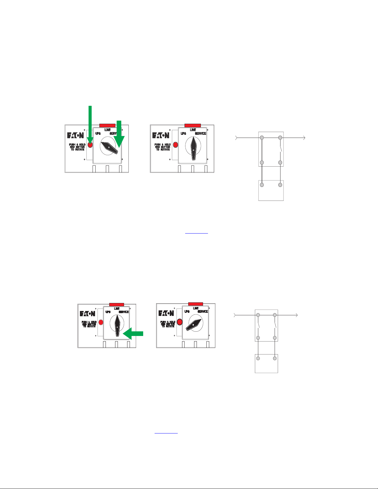
30 4–20kVA Users Guide P-164000669 4–20kVA Users Guide P-164000669—Rev 10
Figure 27. Bypass From UPS to LINE
Depress and HOLD
red button
Rotate switch
to LINE position
LINE
MODE
UTILITY
LOAD
BPM
UPS
FROM
UPS
TO
UPS
INPUT OUTPUT
INPUT OUTPUT
2. Turn the switch from LINE to SERVICE (see Figure 28 ). The critical load is fed directly from utility and the
UPS is now completely disconnected from AC power. Ensure that the UPS is off and the terminals are
completely de-energized before performing any maintenance on the UPS.
Figure 28. Bypass From LINE to SERVICE
Rotate switch
to SERVICE position
SERVICE
MODE
UTILITY
LOAD
BPM
UPS
FROM
UPS
TO
UPS
INPUT OUTPUT
INPUT OUTPUT
33..88 LLoocckk--oouutt//TTaagg--oouutt
The BPM comes with a Lock-out/Tag-out (LOTO) feature to keep the BPM bypass switch locked in SERVICE
mode while qualified service personnel works on the UPS. To use the LOTO feature:
1. Press and hold the red bar (See Figure 29 ).
Lock-out/Tag-out
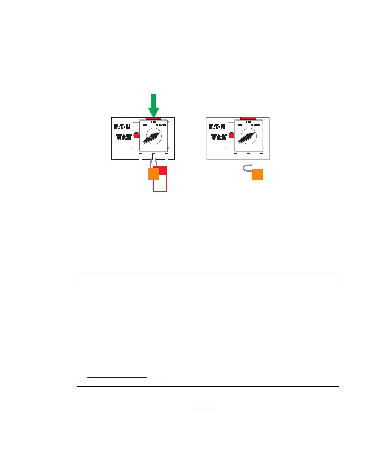
4–20kVA Users Guide P-164000669 4–20kVA Users Guide P-164000669—Rev 10 31
Figure 29. LOTO Feature
Depress and HOLD
red bar
Install lock and tag
in any opening at
the base of switch
Remove Lock and
Tag to reset
LOTO position
2. Install a lock and tag in any opening at the base of the switch according to LOTO procedures.
3. Remove the lock and tag to reset the LOTO position.
33..99 NNoo BBrreeaakk TTrraannssffeerr ffrroomm SSeerrvviiccee BByyppaassss ttoo UUPPSS MMooddee
After the system has been placed into SERVICE mode, it must be returned to UPS state to resume Normal
operation.
Failure to understand the correct bypass sequence and position may cause the critical load to be dropped.
Damage to the power modules or the Bypass switch can occur.
• If the UPS remains in Bypass Mode and incoming AC power is lost, the load is automatically dropped. The
UPS must be in Normal Mode to provide battery backup power.
• In the UPS or LINE position, AC input power is still connected to the input terminals inside the UPS.
• If the UPS is in the standby mode and the bypass switch is in the LINE or UPS positions pressing
the red bypass switch interlock button will energize the UPS output.
• Do not attempt to push the red interlock button or attempt to move the bypass switch handle if the
UPS is operating on battery power.
• If you have any questions or problems with the bypass operation, call the Help Desk (see , “
11.2 Service and Support ” ).
To turn the BPM to UPS Mode:
1. Turn the switch from SERVICE to LINE (see Figure 30 ).
No Break Transfer from Service Bypass to UPS Mode
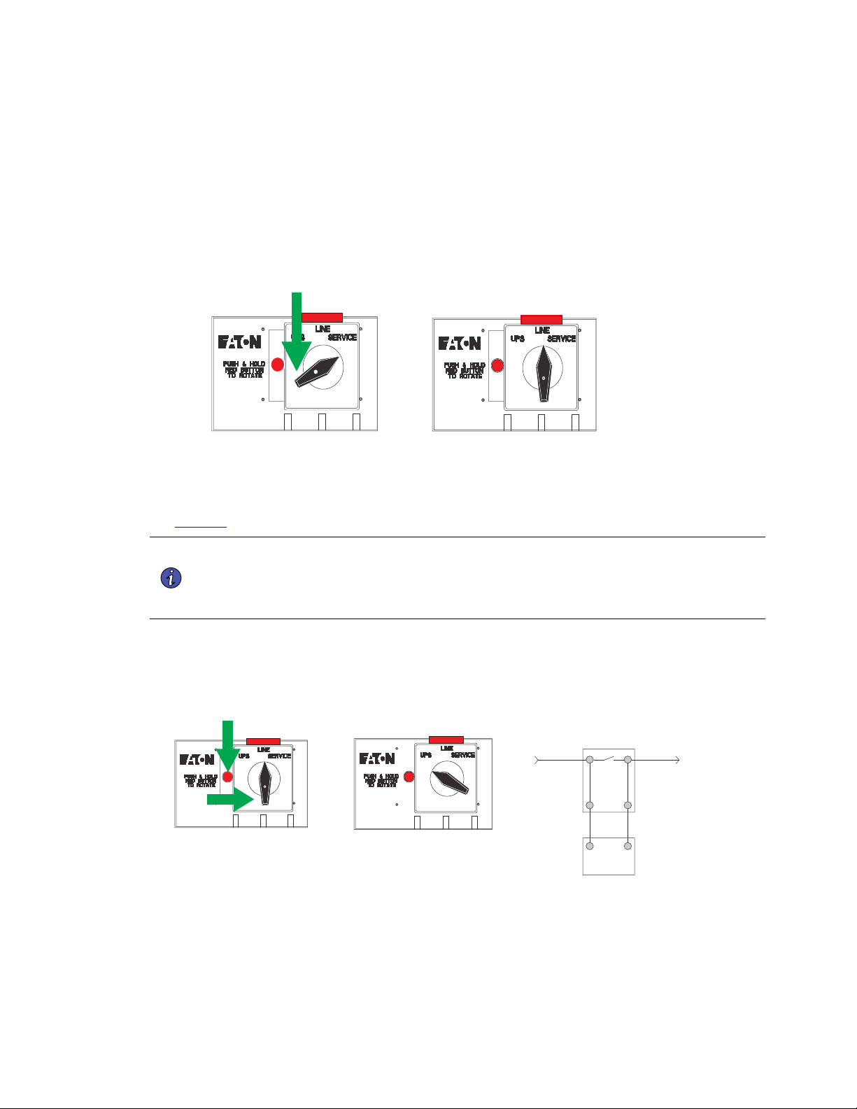
32 4–20kVA Users Guide P-164000669 4–20kVA Users Guide P-164000669—Rev 10
The UPS is now in LINE mode and is energized. It is often best practice to check the UPS status and
configure settings in this mode before transitioning to UPS Mode. Simply check the status of the UPS
through the front LCD menu to ensure the UPS is prepared for use.
Figure 30. From SERVICE to LINE
Rotate switch
to LINE position
2. To transition the UPS from LINE to UPS, press and hold the red button and turn the switch to UPS (see
Figure 31 ).
NOTE 1 Pressing the red button sends the UPS into Bypass Mode. This allows the UPS output
to synchronize with utility for safe, uninterrupted transfer.
NOTE 2 In UPS Mode, the UPS resets from Bypass to UPS Normal Mode ( Online Mode ). This
transition may take as long as 60 seconds.
Figure 31. From LINE to UPS
Rotate switch
to UPS position
UPS
MODE
UTILITY
LOAD
BPM
UPS
FROM
UPS
TO
UPS
INPUT OUTPUT
INPUT OUTPUT
3. Once the switch is in UPS Mode and the UPS is in Normal Mode (Online Mode), the system is in Normal
operation and prepared to provide uninterrupted power to the critical load.
No Break Transfer from Service Bypass to UPS Mode
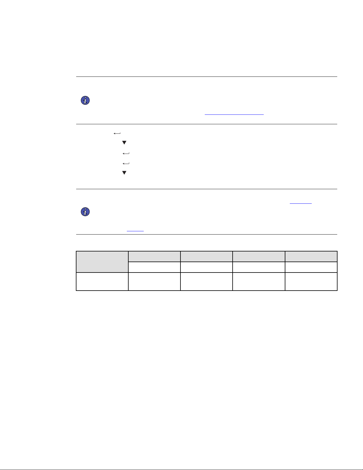
4–20kVA Users Guide P-164000669 4–20kVA Users Guide P-164000669—Rev 10 33
After turning the load position handle to the UPS position and releasing the red button, if the Eaton 9PXM
UPS remains in Bypass Mode, return the UPS to Normal Mode using the following procedure for proper
operation:
NOTE 1 If the UPS remains in Bypass Mode and incoming AC power is lost, the load is
automatically dropped. The UPS must be in Normal Mode to provide battery backup
power.
NOTE 2 If you have any questions or problems with the bypass operation, call the Help Desk at
one of the telephone numbers in 11.2 Service and Support and ask for a UPS technical
representative.
• Press
the button on the front panel display. The main menu screen appears (see ).
• Press the
button to select Control.
• Press the
button. Control menu displays.
• Press the
button to select Go back Normal.
• Press the
button to select Yes and press to return to Normal (UPS) Mode.
• Press ESC twice to return to the Status Menu. The UPS is now in Normal mode.
NOTE 1 The UPS should transfer from Bypass Mode to Normal operation after a period of one
minute automatically provided the Input signals are set correctly. See Figure 23 .
NOTE 2 To disconnect AC input power during maintenance or service, turn the Bypass switch to
the SERVICE position.
NOTE 3 Table 4 shows the bypass switch models available for the Eaton 9PXM UPS.
Table 4. BPM Dimensions
Model
Height Width Depth Weight
(A) (B) (C)
BPM125XX
130 mm
21.0”
440 mm
(14.0”)
663 mm
(6.8”)
17 kg
(38 lb)
No Break Transfer from Service Bypass to UPS Mode

34 4–20kVA Users Guide P-164000669 4–20kVA Users Guide P-164000669—Rev 10
No Break Transfer from Service Bypass to UPS Mode
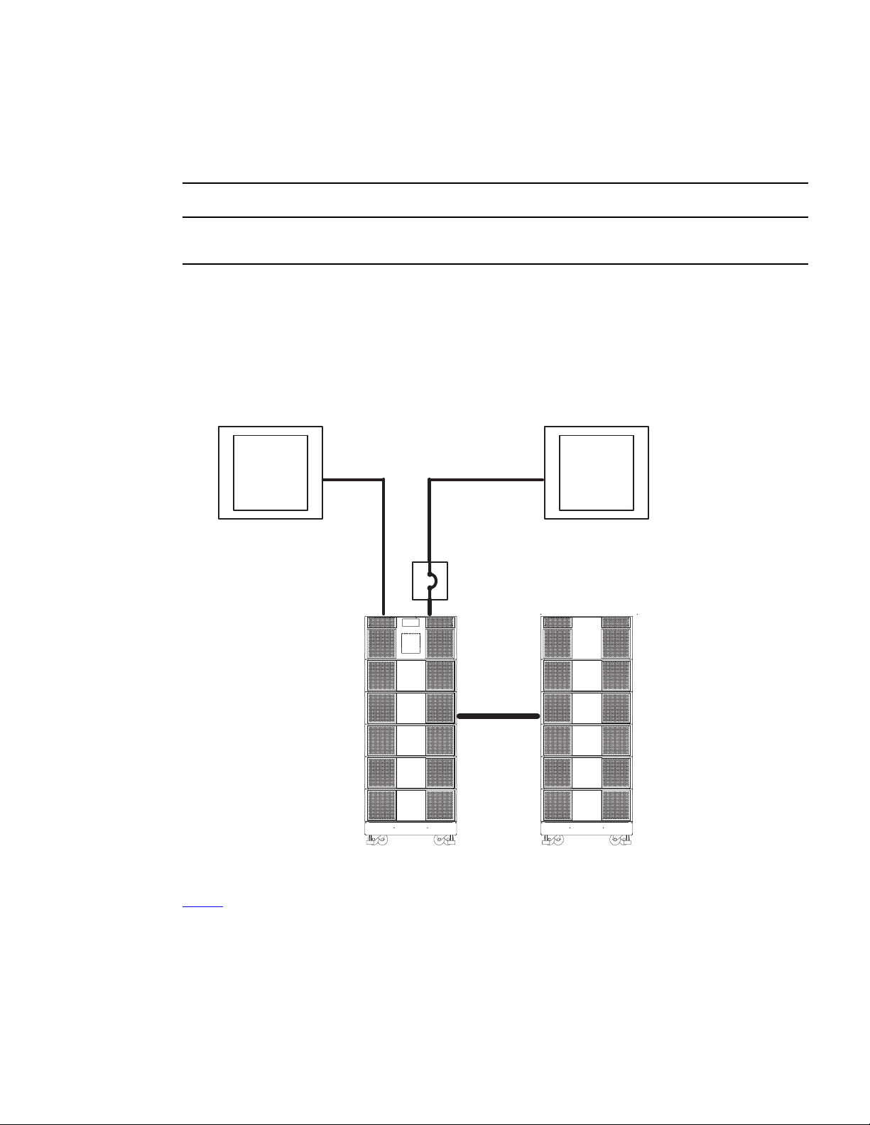
4–20kVA Users Guide P-164000669 4–20kVA Users Guide P-164000669—Rev 10 35
CChhaapptteerr 44 UUPPSS EElleeccttrriiccaall IInnssttaallllaattiioonn
44..11 UUPPSS IInnppuutt CCuurrrreenntt RRaattiinnggss
Risk of electrical shock. Only qualified service personnel (such as a licensed electrician) should perform the
electrical installation in this section.
If a bypass switch is not used, the UPS input may be hardwired through conduit to a main power source circuit
breaker, and the UPS output may either be hardwired to a circuit breaker in a distribution panel (as shown in
Figure 31) or supplied to loads through optional receptacles on the back of the UPS. Without a bypass switch,
power to the load cannot be maintained if the UPS is taken completely offline.
Figure 32. Typical Installation without a Bypass Switch
Building
Service
Panel
Load
Distribution
Panel
User-Supplied
(if required)
External Battery
Module
(optional)
Table 5 contains the required circuit breaker ratings for hardwired installations.

36 4–20kVA Users Guide P-164000669 4–20kVA Users Guide P-164000669—Rev 10
Table 5. UPS Recommended Breaker Sizes
UPS Capacity Input Circuit breaker Rating 75°C Copper Wire Size
4kVA 25A
5.3 mm2 (10 AWG)
8kVA 50A
8.4 mm2 (8 AWG)
12kVA 80A
21.2 mm2 (4 AWG)
16kVA 100A
33.6 mm2 (2 AWG)
20kVA 125A
42.1 mm2 (1 AWG)
NOTE If a super charger is installed in an EBM, the circuit breaker for the AC input to EBM
must be a 25 A breaker with 5.3 mm2 (10 AWG) copper wire.
NOTE To accommodate the feature of easy system expendability, it is recommended that
initial installation of the Eaton 9PXM UPS contains wiring to support the maximum
capacity of the UPS cabinet : 20kVA for 12–slot cabinets and 16kVA for 8 slot chassis.
See for recommended conductor sizes to wire the input circuit breakers.
Table 6. UPS Recommended Wire Sizes
Input Breaker Size 75° Copper Wire Size Conductor Screw Tourqe
25A
5.3 mm2 (10 AWG) 4.0 Nm (35 lb in)
50A
8.4 mm2 (8 AWG) 4.5 Nm (40 lb in)
80A
21.2 mm2 (4 AWG) 5.1 Nm (45 lb in)
100A
33.6 mm2 (2 AWG) 6.6 Nm (50 lb in)
125A
42.1 mm2 (1 AWG) 6.6 Nm (50 lb in)
!
IMPORTANT
FOR U.S. INSTALLATIONS, READ THIS IMPORTANT NOTE
• lists the mm2 and AWG wire size for each circuit breaker size shown on the wiring diagrams. The
minimum recommended circuit breaker sizes for each model and voltage application are listed on the
wiring diagrams.
• Conductor sizes shall be no smaller than the 75°C wire size based on the ampacities given in Table 310.15
(B)(16) of the National Electrical Code® (NEC®), ANSI/NFPA 70-2017, and article 220. All circuit
conductors, including the neutral conductor, must be the same size (ampacity) wire. Code may require a
larger AWG size than shown in this table because of temperature, number of conductors in the conduit, or
long service runs. Follow local code requirements.
UPS Input Current Ratings
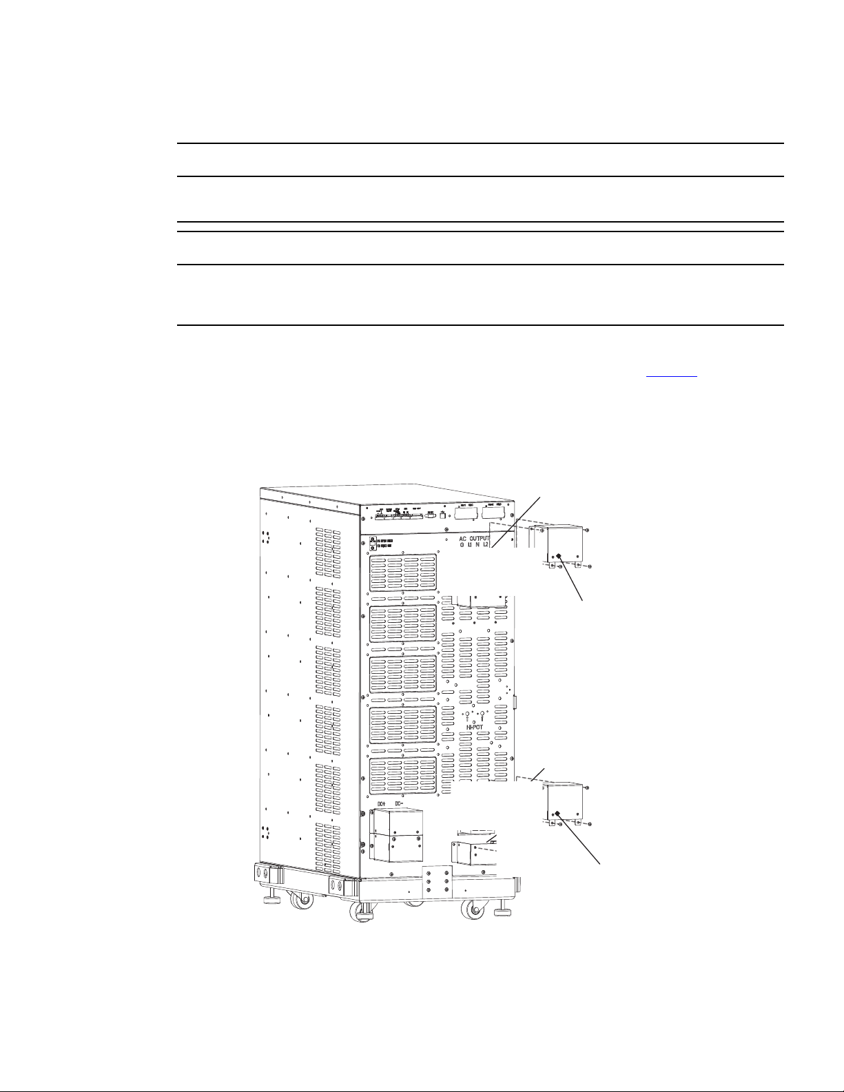
4–20kVA Users Guide P-164000669 4–20kVA Users Guide P-164000669—Rev 10 37
44..22 UUPPSS EElleeccttrriiccaall IInnssttaallllaattiioonn
Only qualified service personnel (such as a licensed electrician) should perform the electrical installation. Risk of
electrical shock.
To prevent electrical shock or damage to the equipment, verify that the Eaton 9PXM UPS is OFF before you
remove the terminal covers. The circuit breaker or disconnect switch must also be OFF at the AC input service
panel.
To install the UPS without an external bypass switch:
1. Install the AC terminal upper covers supplied in the accessory kit of the UPS (See Figure 33 ) . The AC
input terminal block is located on the lower right side and the AC output on the upper right side of the UPS
rear panel.
Figure 33. UPS Power Terminals
AC Input Terminals
Terminal Cover
Terminal Cover
AC Output Terminals
UPS Electrical Installation
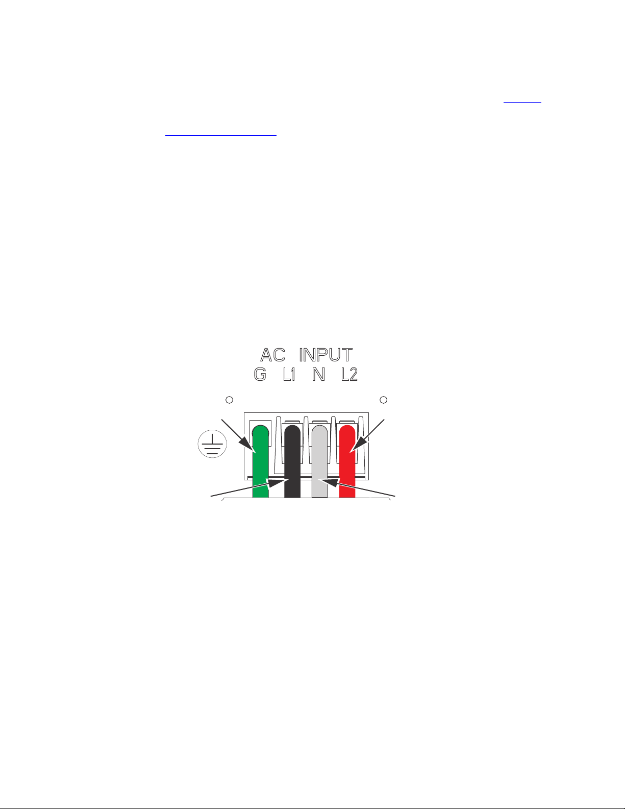
38 4–20kVA Users Guide P-164000669 4–20kVA Users Guide P-164000669—Rev 10
2. At the AC Input terminal, make sure to wire the UPS for the proper input voltage as shown in Figure 34 .
Split-phase power modules provide a 2-phase output which can be configured as output voltages: 110/110
for 220, 120/120 for 240, 120/120 for 208, or 127/127 for 220 Vac, as selected through the front panel
display (“7.15 Display Menu Screens ”).
Figure 34. Split-Phase Power Modules
Split-Phase Power Modules
(3-wire plus ground input) (2 PEN)
110/220, 120/208, 120/240, 127/220 Vac
L2
N
GND
L1
UPS Electrical Installation
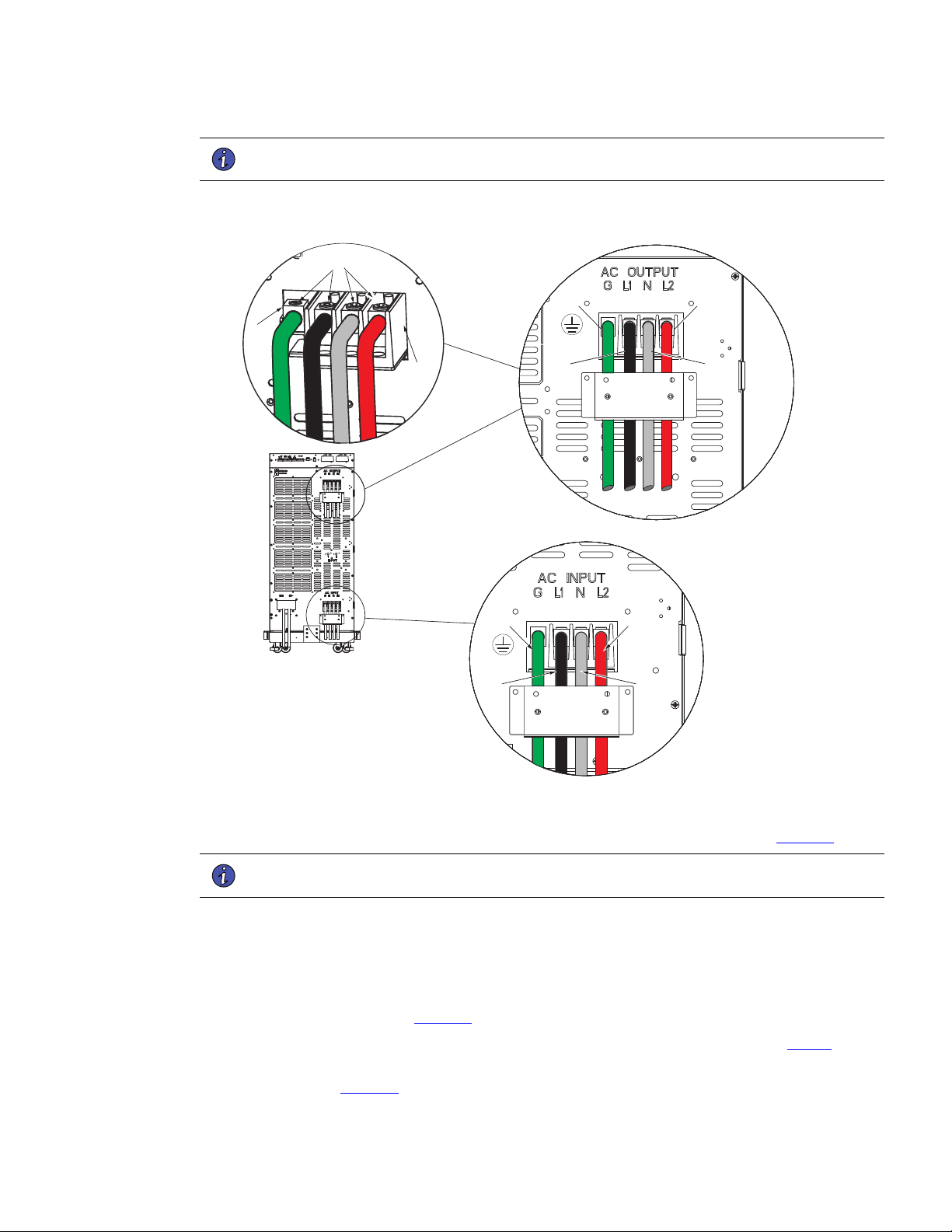
4–20kVA Users Guide P-164000669 4–20kVA Users Guide P-164000669—Rev 10 39
NOTE UPS output circuits must be installed in separate conduit systems and not shared with
other electrical circuits.
Figure 35. UPS Input and Output Terminal Connections
L2
N
GND
L1
AC Input
Connections
AC Output
Connections
N
L2
GND
L1
L1
AC Terminal
Blocks
Lug Screws
Terminal
Block
Ground
Lug
3. Make the UPS input and output connections to the terminal blocks on the rear panel (see Figure 35 ):
NOTE UPS output circuits must be installed in separate conduit systems and not shared with
other electrical circuits.
a. Insert the L1, N and L2 cable ends into the applicable terminal slots on the terminal block.
b. Insert the G (GND) cable end into the ground lug on the rear panel.
c. Secure the cables by screwing down the lug screws.
4. Route and connect the AC input cables to the building service panel and the AC output cables to the load
distribution panel as shown in Figure 36 .
5. Torque the screws holding all input and output power conductors to the values specified in Table 6 .
6. Install the supplied wiring connectors to the UPS input control signal wires and connect to the terminals as
shown in . See , “ Figure 74 ” from signal terminal identification.
UPS Electrical Installation

40 4–20kVA Users Guide P-164000669 4–20kVA Users Guide P-164000669—Rev 10
7. When all connections have been made and checked, reinstall the UPS terminal covers using the original.
8. If floor anchor brackets were installed and not secured, install the floor bolts (
2.5 Anchor Bracket Installation ).
9. After electrical installation is complete, you must also set the output settings menu at UPS startup (
6.1 UPS Startup ) for the required output voltage as shown in the wiring configuration drawings (
7.15 Display Menu Screens ).
Risk of electrical shock. Only qualified service personnel (such as a licensed electrician) should perform the
electrical installation in this section.
44..33 SSyysstteemm WWiirriinngg DDiiaaggrraamm
NOTE 1 The customer must provide input overcurrent protection. See NEC Section 240-21
or local requirements. See Table 5 for circuit breaker ratings to size the protection device
according to local code requirements.
NOTE 2 The customer must size the AC circuit conductors. All AC circuit conductors,
including the neutral conductor, must be the same size ( ampacity ), have the same
rating (75°C) copper wire, and be sized according to the input circuit breaker. See
Table 6 for recommended wire sizes. The UPS input and output conductors must be run
through separate conduits.
NOTE 3 The customer must provide output overcurrent protection. See NEC Section 240-21
or local requirements. See Table 5 for maximum output overcurrent protection device
ratings.
NOTE 4 See “2.1 Preparing for Installation ” for installation and service clearances before
installing the UPS. Use flexible conduit on the UPS or the external battery cabinet if
either must be moved.
NOTE 5 External UPS battery cabinets are optional. See “
5.2 Standard Battery Cabinet Installation or 5.1 Battery Cabinet Options ” for installation
instructions.
NOTE 6 UPS output circuits shall be installed in dedicated conduit systems and not shared with
other electrical circuits.
NOTE 7 Use only Eaton-supplied power cables between the UPS and EBM(s) (PN:P-103003231).
NOTE 8 CN3 and CN4 CAN cables ground separately to each cabinet chassis.
System Wiring Diagram
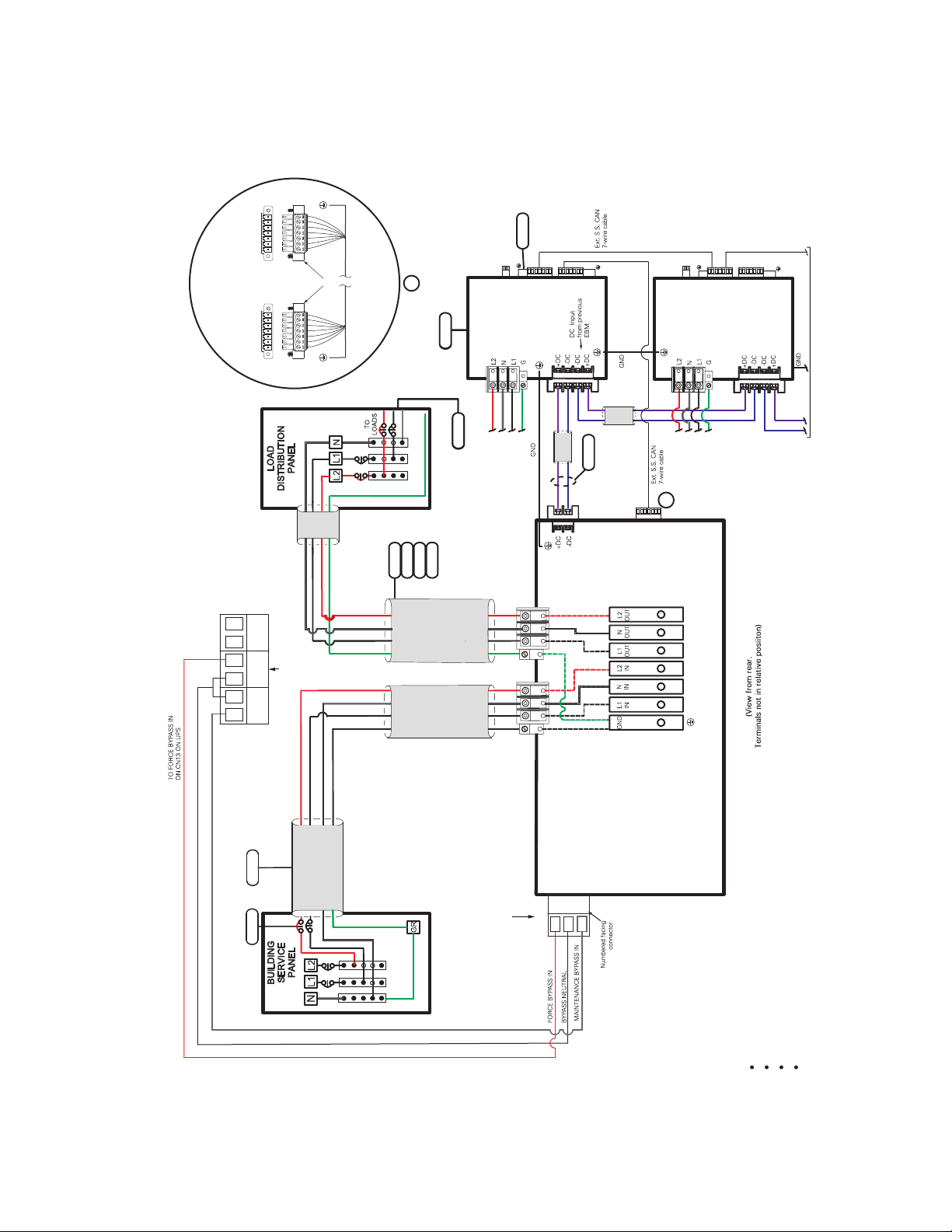
4–20kVA Users Guide P-164000669 4–20kVA Users Guide P-164000669—Rev 10 41
Figure 36. UPS with No External Bypass (L1,L2,N)
Figure 35. Wiring Diagram - UPS with No External Bypass (L1, L2, N)
1
2
3
5
6
3
2
4
6
110/220 Input, 110/220 Output
120/208 Input, 120/208 Output
120/240 Input, 120/240 Output
127/220 Input, 127/220 Output
INPUT / OUTPUT
POWER BUS BAR
CN13
UPS NO AUX NO AUX NC
3
2
1
INPUT FROM
FACILITY
EXTERNAL
DC
AC
OUTPUT
AC
INPUT
UPS
UPS INPUT
SIGNALS
CN3
CN4
CN6
CN6
CN4
5
6
AC INPUT
TO EBM 1
AC INPUT
TO EBM 2
TO NEXT EBM
(If installed)
DC
INPUT
EBM 1
}
EBM 2
CN3
CN4
CN3
CN4
7
A
A
G
L2L1 N
G
L2
L1
N
7 6 5 4 3 2 1* 7 6 5 4 3 2 1
UPS
CN4
EBM
CN4
Supplied
Connectors
*Pin numbering
is right-to-left
Input Signal connections
(Typical)
8
System Wiring Diagram

42 4–20kVA Users Guide P-164000669 4–20kVA Users Guide P-164000669—Rev 10
System Wiring Diagram

4–20kVA Users Guide P-164000669 4–20kVA Users Guide P-164000669—Rev 10 43
CChhaapptteerr 55 BBaatttteerryy CCaabbiinneett IInnssttaallllaattiioonn
55..11 BBaatttteerryy CCaabbiinneett OOppttiioonnss
SSttaannddaarrdd BBaatttteerryy CCaabbiinneett OOppttiioonn
The “Standard” battery cabinet option is available in 8 or 12 slot chassis sizes. The “Standard” battery cabinet
does not have the capability for automatic monitoring via CAN communication. The “Standard” cabinet also
does not support the installation of a super charger module.
• 5.2 Standard Battery Cabinet Installation for extended runtime battery support. There is no capability of
using a super charger module with this option.
CCoonnnneecctteedd BBaatttteerryy CCaabbiinneett OOppttiioonnss
The “Connected” battery cabinet option is available in 8 or 12 slot chassis sizes. The “Connected” battery
cabinet does have the capability for automatic monitoring via CAN communication. The “Connected” cabinet
does support the installation of a super charger module depending on the type of installation.
The following installation options are available for a “Connected” battery cabinet:
• 5.3 Connected Battery Cabinet With No AC Input used for extended runtime battery support only. There is
no capability of using a super charger module with this option.
• 5.4 Connected Battery Cabinet With 120VAC Input used for automatic monitoring via CAN communication
and extended runtime battery support. No capability of using a super charger module with this option.
• 5.5 Connected Battery Cabinet With Split Phase Input used for automatic monitoring via CAN
communication and extended runtime battery support. Capability of using a super charger module with
this option..
55..22 SSttaannddaarrdd BBaatttteerryy CCaabbiinneett IInnssttaallllaattiioonn
• Make sure all AC power is removed from the UPS. Observe all electrical safety precautions.
• Only qualified service personnel (such as a licensed electrician) should perform the battery cabinet
installation. Risk of electrical shock.
• Before connecting an external battery cabinet to the UPS cabinet or to another external battery cabinet,
verify that all AC input power is removed from the UPS. Open the input service circuit breaker or turn the
external bypass switch to the SERVICE position. Observe all electrical safety precautions.
• Remove all battery modules in the UPS cabinet and/or battery cabinet to ensure DC voltage is removed
from the internal DC buses.
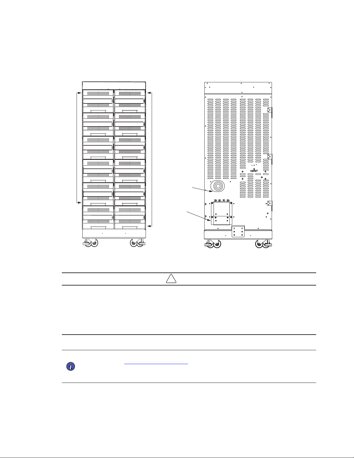
44 4–20kVA Users Guide P-164000669 4–20kVA Users Guide P-164000669—Rev 10
Figure 37. Standard EBM Front and Back
Battery
Modules
Battery
Modules
EBM Front View
(Covers removed)
UPS DC
Terminal
Covers
DC Emergency
Disconnect
Switch
EBM
EBM Front EBM Back
!
IMPORTANT
• If you are installing multiple EBM(s) upstream to the UPS, repeat the setup as described in this section.
• The battery cables are supplied inside the battery cabinet accessory kit.
• In the UPS cabinet, the proper location of cabinet-to-cabinet DC wiring is on the lower left of the rear panel.
• All of the slots in the Standard 8 and 12 slot battery cabinets can be populated with batteries.
Prepare the EBM Cabinet
NOTE 1 The external battery cabinets are the same dimensions as the UPS cabinets. Refer to
the ” 2.1 Preparing for Installation ” section for unpacking and cabinet setup.
NOTE 2 If you are installing multiple EBM(s) upstream to the UPS, repeat the setup as described
in this section.
1. Open the carton containing the external battery cabinet cable assembly and position it in the desired
location next to the UPS.
Standard Battery Cabinet Installation
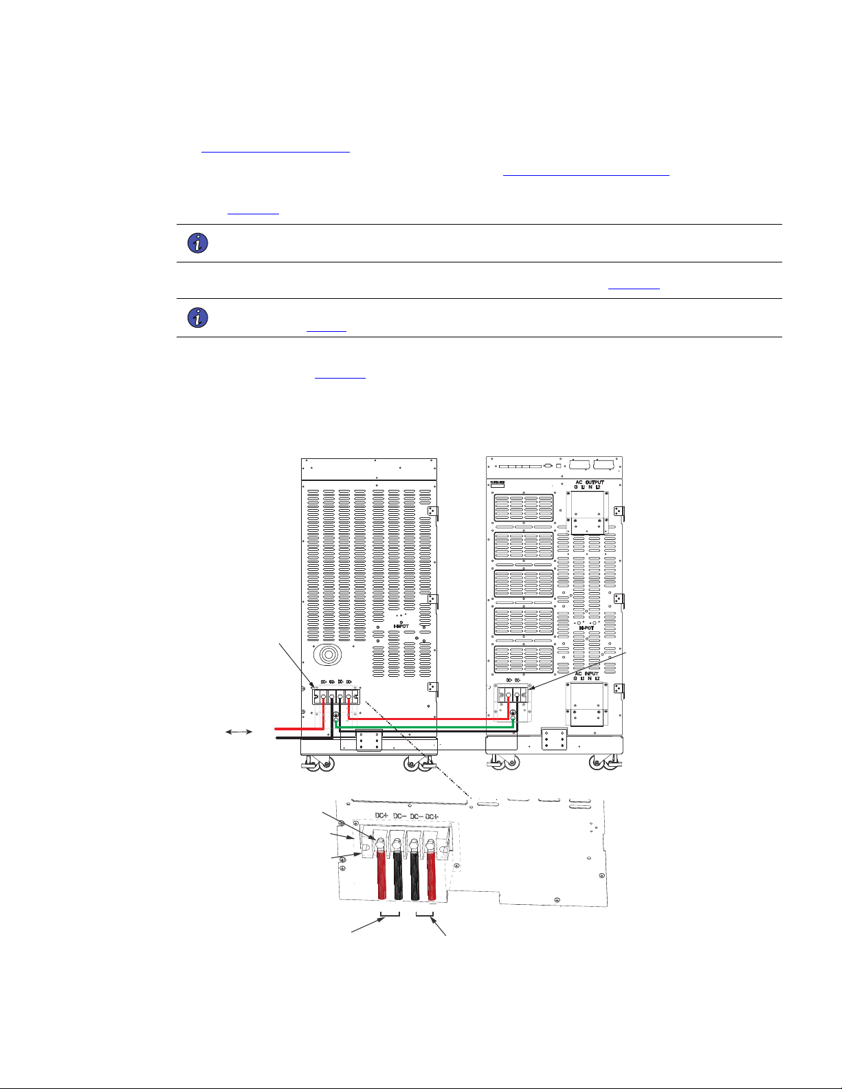
4–20kVA Users Guide P-164000669 4–20kVA Users Guide P-164000669—Rev 10 45
2. If you are rack-mounting the EBM cabinet, refer to the UPS rack-mount installation procedure (see
2.6 Rack-Mount Installation ). If not, proceed to the next step.
3. Install the anchor brackets to the floor if applicable (see 2.5 Anchor Bracket Installation ).
4. Push in the EBM DC emergency disconnect switch on the rear EBM panel and turn the switch lockout key
(see Figure 37 ).
NOTE The UPS and EBM AC/DC terminal covers are shipped in the UPS and EBM accessory
kit and do not come installed on the UPS or EBM chassis.
1. Route the EBM DC input/output cables to the terminal blocks as shown in (Figure 38).
NOTE Torque the screws holding all input and output power conductors to the values specified
in Table 2 .
2. Connect the EBM DC Cables to the applicable terminals by removing and reinstalling the screws onto the
terminal blocks. See Figure 38.
Figure 38. Standard EBM to UPS Connections
EBM Terminal
Blocks
UPS/EBM
Terminal
Block
From previous
EBM
(if installed)
CN4
EBM UPS
DC+
DC-
DC+
DC-
Screws
Cover
DC+ DC- DC- DC+
To UPS
DC input cables from
upstream EBM
(if installed)
Terminal
Block
Standard Battery Cabinet Installation
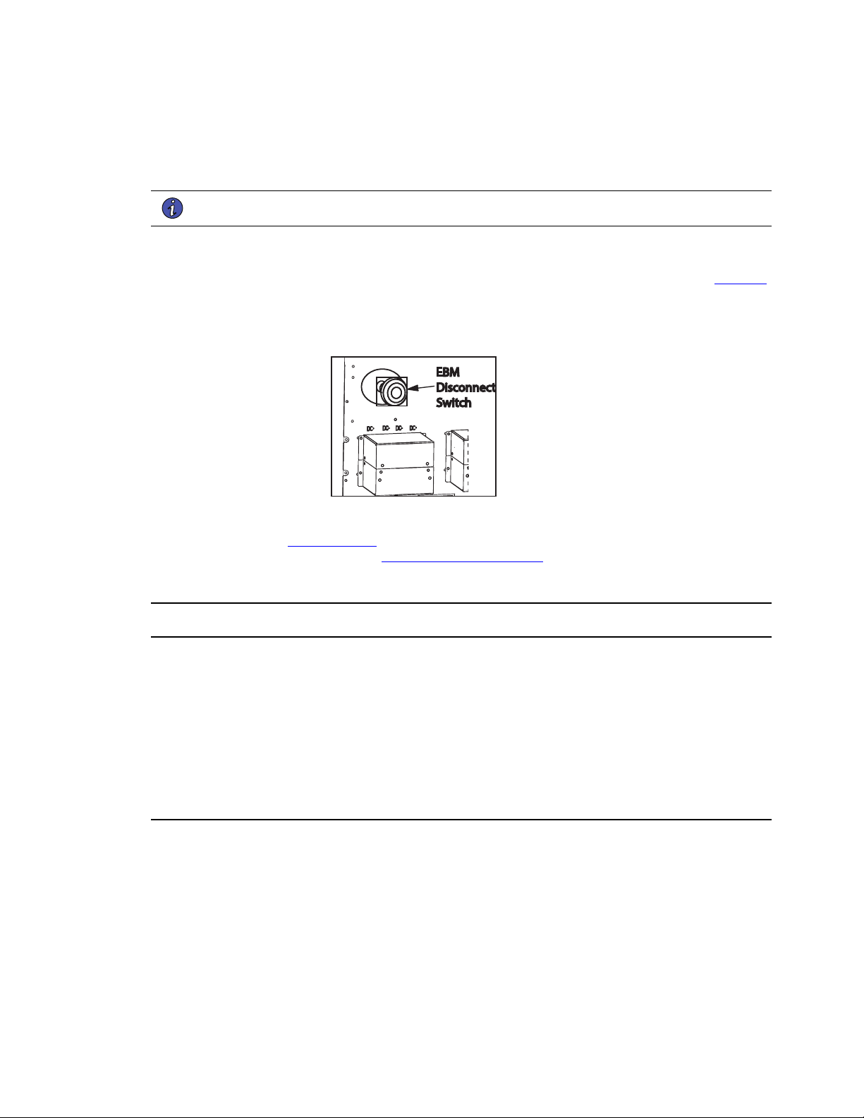
46 4–20kVA Users Guide P-164000669 4–20kVA Users Guide P-164000669—Rev 10
3. Reinstall the AC and DC terminal covers.
4. If additional battery cabinets are to be connected to the first, in a daisy-chain configuration, connect each
EBM with the DC cables supplied in the EBM accessory kit.
NOTE DC input cables only required if EBM(s) are installed upstream.
5. Close the DC emergency disconnect switch button on the back of each EBM. Insert the switch key
supplied with the cabinet into the button and turn clockwise 1/2-turn. Pull the button OUT to close the
switch and reconnect DC power. Turn the key back counter-clockwise, and remove the key (see Figure 39
).
Figure 39. EBM Emergency Disconnect Switch
EBM
Disconnect
Switch
6. Proceed to Chapter 6.1 UPS Startup and be sure to set the number of external battery strings on the UPS
LCD for calculating the runtime. See 6.5 Initial Startup Parameters.
55..33 CCoonnnneecctteedd BBaatttteerryy CCaabbiinneett WWiitthh NNoo AACC IInnppuutt
• Make sure all AC power is removed from the UPS. Observe all electrical safety precautions.
• Only qualified service personnel (such as a licensed electrician) should perform the battery cabinet
installation. Risk of electrical shock.
• Before connecting an external battery cabinet to the UPS cabinet or to another external battery cabinet,
verify that all AC input power is removed from the UPS. Open the input service circuit breaker or turn the
external bypass switch to the SERVICE position. Observe all electrical safety precautions.
• Remove all battery modules in the UPS cabinet and/or battery cabinet to ensure DC voltage is removed
from the internal DC buses.
Connected Battery Cabinet With No AC Input
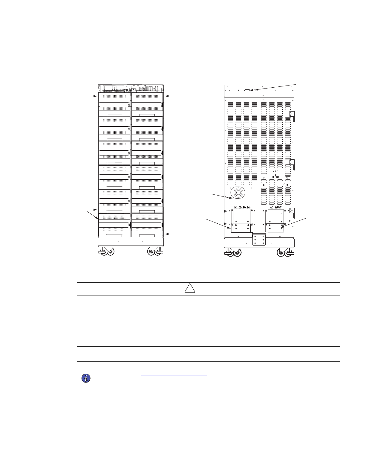
4–20kVA Users Guide P-164000669 4–20kVA Users Guide P-164000669—Rev 10 47
Figure 40. Connected EBM Front And Back
Super
Charger
Battery
Modules
Battery
Modules
EBM Front View
(Covers removed)
UPS DC
Terminal
Covers
DC Emergency
Disconnect
Switch
Communication
Ports
EBM
UPS AC
Terminal
Covers
EBM Front EBM Back
!
IMPORTANT
• If you are installing multiple EBM(s) upstream to the UPS, repeat the setup as described in this section.
• The battery cables are supplied inside the battery cabinet accessory kit.
• In the UPS cabinet, the proper location of cabinet-to-cabinet DC wiring is on the lower left of the rear panel.
• All of the slots in the Standard 8 and 12 slot battery cabinets can be populated with batteries.
PPrreeppaarree tthhee EEBBMM CCaabbiinneett
NOTE 1 The external battery cabinets are the same dimensions as the UPS cabinets. Refer to
the ” 2.1 Preparing for Installation ” section for unpacking and cabinet setup.
NOTE 2 If you are installing multiple EBM(s) upstream to the UPS, repeat the setup as described
in this section.
1. Open the carton containing the external battery cabinet cable assembly and position it in the desired
location next to the UPS.
Connected Battery Cabinet With No AC Input
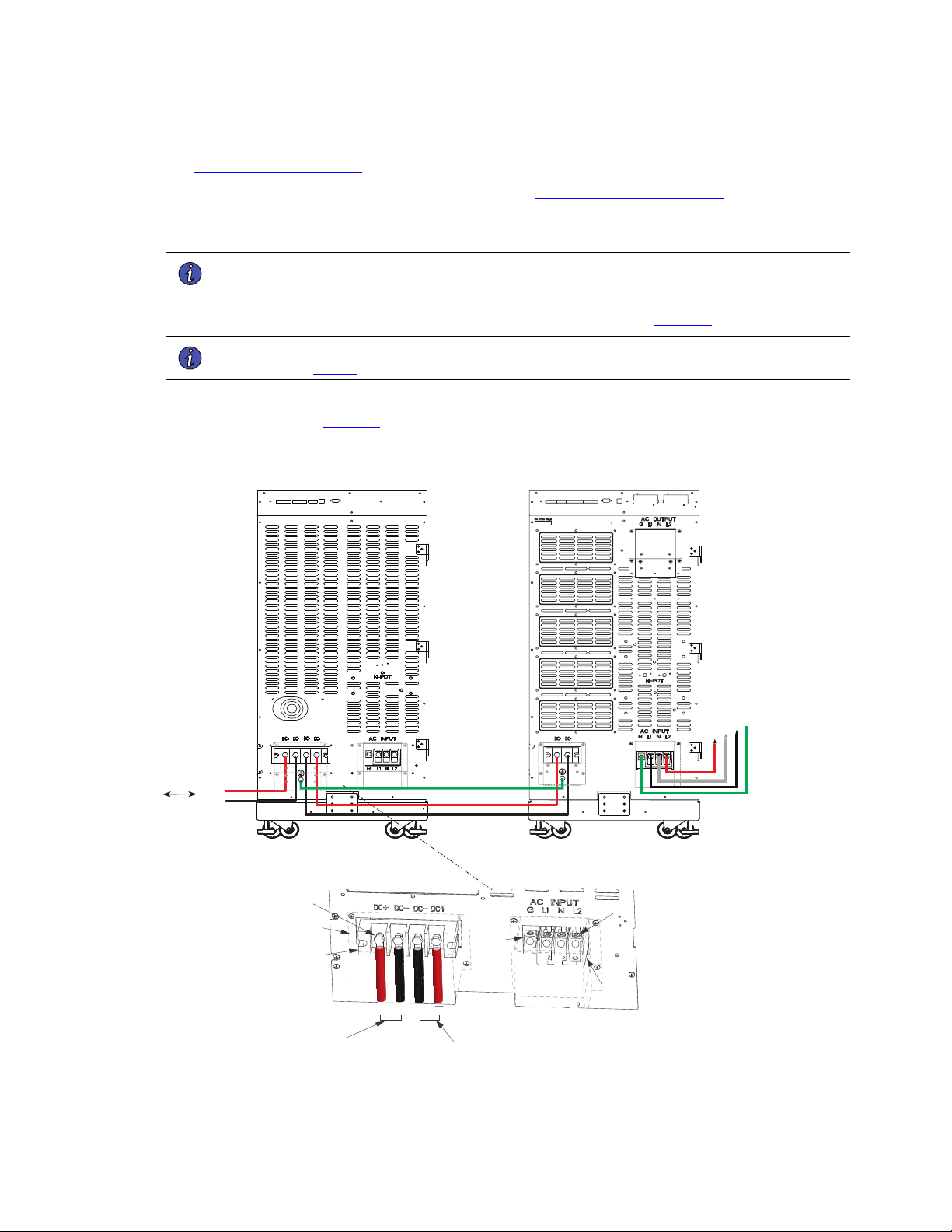
48 4–20kVA Users Guide P-164000669 4–20kVA Users Guide P-164000669—Rev 10
2. If you are rack-mounting the EBM cabinet, refer to the UPS rack-mount installation procedure (see
2.6 Rack-Mount Installation ). If not, proceed to the next step.
3. Install the anchor brackets to the floor if applicable (see 2.5 Anchor Bracket Installation ).
4. Push in the EBM DC emergency disconnect switch on the rear EBM panel and turn the switch lockout key
(see ).
NOTE The UPS and EBM AC/DC terminal covers are shipped in the UPS and EBM accessory
kit and do not come installed on the UPS or EBM chassis.
5. Route the EBM DC input/output cables to the terminal blocks as shown in (Figure 41).
NOTE Torque the screws holding all input and output power conductors to the values specified
in Table 2 .
6. Connect the EBM DC Cables to the applicable terminals by removing and reinstalling the screws onto the
terminal blocks. See Figure 41.
Figure 41. Connected EBM (No AC Input Option)
From previous
EBM
(if installed)
CN3CN4
CN4
EBM
UPS
DC+
DC-
DC+
DC-
L1
G
N
L2
Screws
Screws
Ground
Lug
Cover
DC+ DC- DC- DC+
G L1 N L2
To UPS
DC input cables from
upstream EBM
(if installed)
Terminal
Block
Terminal
Block
Connected Battery Cabinet With No AC Input
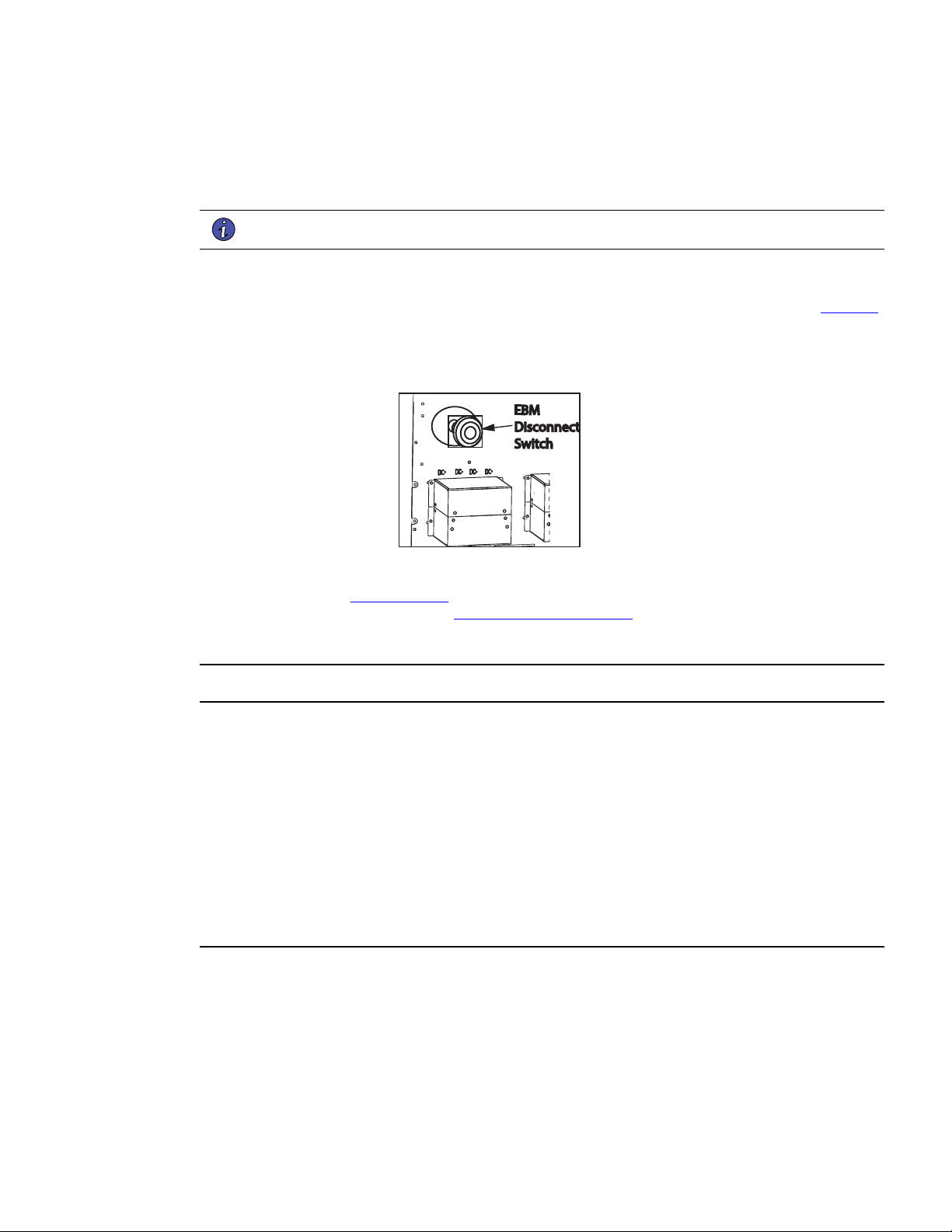
4–20kVA Users Guide P-164000669 4–20kVA Users Guide P-164000669—Rev 10 49
7. Reinstall the AC and DC terminal covers.
8. If additional battery cabinets are to be connected to the first, in a daisy-chain configuration, connect each
EBM with the DC cables supplied in the EBM accessory kit. ).
NOTE DC input cables only required if EBM(s) are installed upstream.
9. Close the DC emergency disconnect switch button on the back of each EBM. Insert the switch key
supplied with the cabinet into the button and turn clockwise 1/2-turn. Pull the button OUT to close the
switch and reconnect DC power. Turn the key back counter-clockwise, and remove the key (see Figure 42
).
Figure 42. EBM Emergency Disconnect Switch
EBM
Disconnect
Switch
10. Proceed to Chapter 6.1 UPS Startup and be sure to set the number of external battery strings on the UPS
LCD for calculating the runtime. See 6.5 Initial Startup Parameters.
55..44 CCoonnnneecctteedd BBaatttteerryy CCaabbiinneett WWiitthh 112200VVAACC IInnppuutt
• Make sure all AC power is removed from the UPS. Observe all electrical safety precautions.
• Only qualified service personnel (such as a licensed electrician) should perform the battery cabinet
installation. Risk of electrical shock.
• For the 120V connected battery cabinet wiring option the EBM AC must be installed on its own dedicated
15 amp circuit, Do not connect the EBM AC input to the UPS.
• Before connecting an external battery cabinet to the UPS cabinet or to another external battery cabinet,
verify that all AC input power is removed from the UPS. Open the input service circuit breaker or turn the
external bypass switch to the SERVICE position. Observe all electrical safety precautions.
• Remove all battery modules in the UPS cabinet and/or battery cabinet to ensure DC voltage is removed
from the internal DC buses.
Connected Battery Cabinet With 120VAC Input

50 4–20kVA Users Guide P-164000669 4–20kVA Users Guide P-164000669—Rev 10
Figure 43. Connected EBM Front And Back
Super
Charger
Battery
Modules
Battery
Modules
EBM Front View
(Covers removed)
UPS DC
Terminal
Covers
DC Emergency
Disconnect
Switch
Communication
Ports
EBM
UPS AC
Terminal
Covers
EBM Front EBM Back
!
IMPORTANT
• The external battery cabinets are the same dimensions as the UPS cabinets. Refer to the ”
2.1 Preparing for Installation ” section for unpacking and cabinet setup.
• If you are installing multiple EBM(s) upstream to the UPS, repeat the setup as described in this section.
• The battery cables are supplied inside the battery cabinet accessory kit.
• In the UPS cabinet, the proper location of cabinet-to-cabinet DC wiring is on the lower left of the rear panel.
• All of the slots in the Standard 8 and 12 slot battery cabinets can be populated with batteries.
PPrreeppaarree tthhee EEBBMM CCaabbiinneett
1. Open the carton containing the external battery cabinet cable assembly and position it in the desired
location next to the UPS.
NOTE The UPS / EBM AC/DC terminal covers are shipped in the UPS and EBM accessory kit
and do not come installed on the UPS or EBM chassis.
Connected Battery Cabinet With 120VAC Input
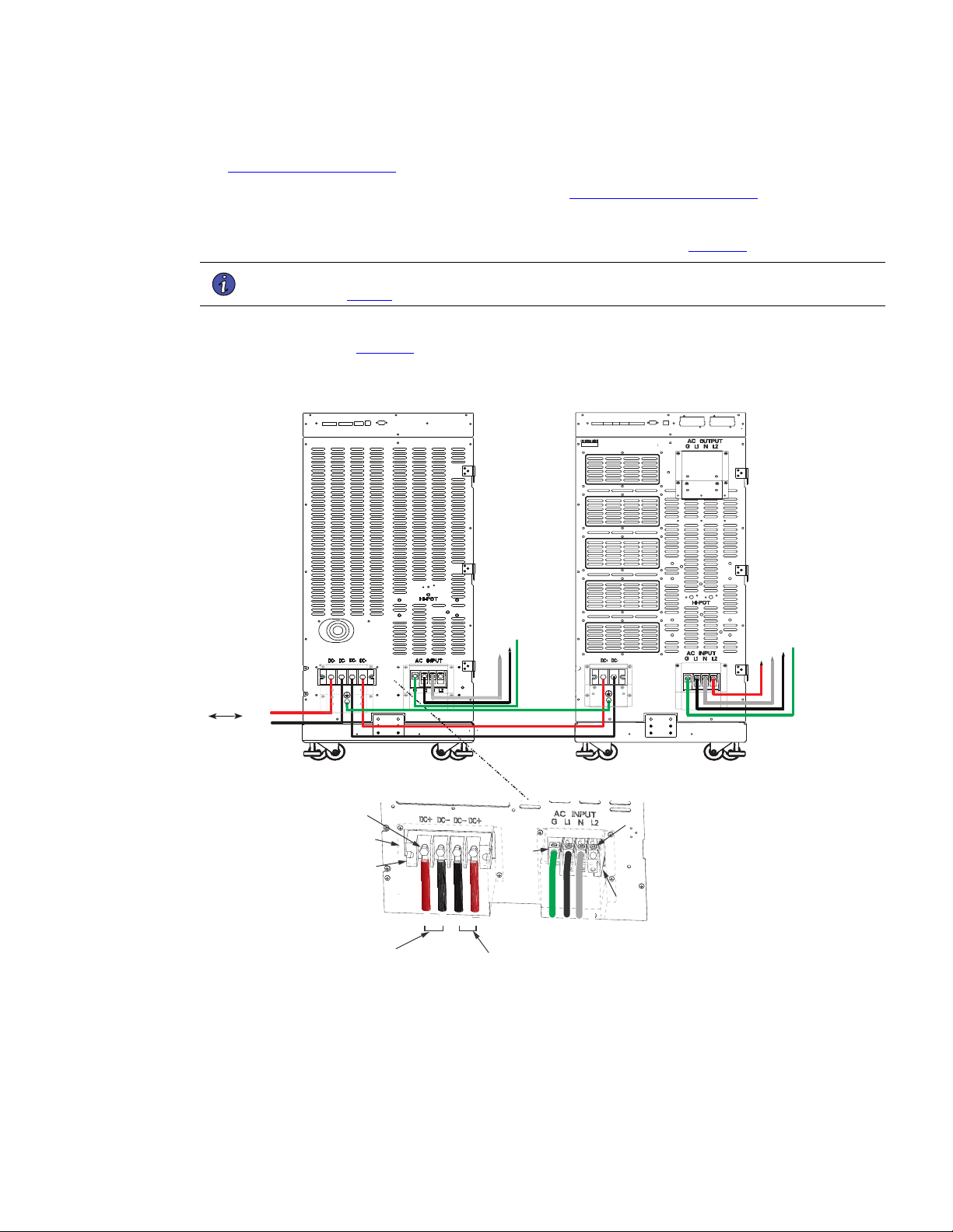
4–20kVA Users Guide P-164000669 4–20kVA Users Guide P-164000669—Rev 10 51
2. If you are rack-mounting the EBM cabinet, refer to the UPS rack-mount installation procedure (see
2.6 Rack-Mount Installation ). If not, proceed to the next step.
3. Install the anchor brackets to the floor if applicable (see 2.5 Anchor Bracket Installation ).
4. Push in the EBM DC emergency disconnect switch on the rear EBM panel and turn the switch lockout key.
5. Route the EBM DC input/output cables to the terminal blocks as shown in (Figure 44).
NOTE Torque the screws holding all input and output power conductors to the values specified
in Table 2 .
6. Connect the EBM DC Cables to the applicable terminals by removing and reinstalling the screws onto the
terminal blocks. See Figure 44.
Figure 44. Connected EBM (120V AC Option)
From previous
EBM
(if installed)
CN3CN4
CN4
EBM
UPS
DC+
DC-
DC+
DC-
L1
G
N
L2
N
L1
G
Screws
Screws
Ground
Lug
Cover
DC+ DC- DC- DC+
G L1 N L2
To UPS
DC input cables from
upstream EBM
(if installed)
Terminal
Block
Terminal
Block
7. Reinstall the AC and DC terminal covers.
8. If additional battery cabinets are to be connected to the first, in a daisy-chain configuration, connect each
EBM with the DC cables supplied in the EBM accessory kit.
Connected Battery Cabinet With 120VAC Input
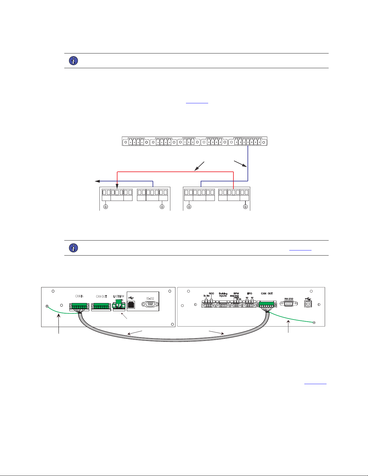
52 4–20kVA Users Guide P-164000669 4–20kVA Users Guide P-164000669—Rev 10
NOTE DC input cables only required if EBM(s) are installed upstream.
9. On the upper rear UPS and EBM panels, connect the input signal cables from the EBM CN4 to the UPS
input signal port CN4 using the supplied cables. (See ).
10. If additional battery cabinets are to be connected to the first, in a daisy-chain configuration, connect each
EBM with signal cables from CN3 to CN4 (see Figure 45 ).
Figure 45. UPS Input Control Signal Wiring (For External Controls)
EPO
(CN7)
To EBM(s)
UPS
ROO and On Generator
(CN6)
External CAN
(CN4)
To previous (upstream)
EBM CN4
Signal cables and
connectors (supplied)
EBM 1
EBM 2
CAN OUT
(CN3)
CAN OUT
(CN3)
CAN IN
(CN4)
CAN IN
(CN4)
11. Connect the CAN cable ground wires to the EBM chassis.
NOTE Connect each CAN ground wires to separate screws on the chassis. See Figure 46 .
Figure 46. Securing The CAN Ground Wire
Grey EBM CAN Communication Cable
2 17 117
CN3
CN4
CAN IN
CAN OUT
LAST EBM
JUMPER
NOT FOR CUSTOMER USE
RS-232
Secure Green and Yellow CAN
cable ground wire to the chassis
Green Terminal Jumper
in Last EBM
EBM 1
UPS
Secure Green and Yellow CAN
cable ground wire to the chassis
12. Close the DC emergency disconnect switch button on the back of each EBM. Insert the switch key
supplied with the cabinet into the button and turn clockwise 1/2-turn. Pull the button OUT to close the
switch and reconnect DC power. Turn the key back counter-clockwise, and remove the key (see Figure 47
).
Connected Battery Cabinet With 120VAC Input
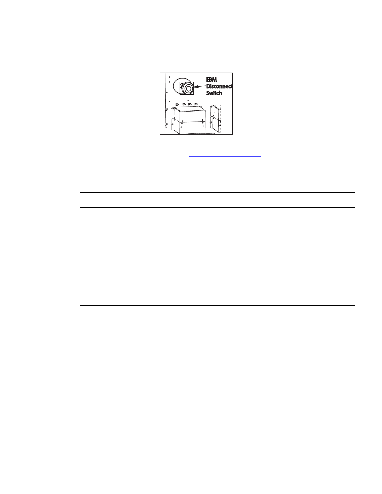
4–20kVA Users Guide P-164000669 4–20kVA Users Guide P-164000669—Rev 10 53
Figure 47. EBM Emergency Disconnect Switch
EBM
Disconnect
Switch
13. Proceed to Chapter 6 UPS Startup. See 6.5 Initial Startup Parameters .
55..55 CCoonnnneecctteedd BBaatttteerryy CCaabbiinneett WWiitthh SSpplliitt PPhhaassee IInnppuutt
The connected Eaton 9PXM split phase input option will provide the UPS additional extended runtime and external battery
string monitoring. Use of a supercharger is also supported with this installation option.
• Make sure all AC power is removed from the UPS. Observe all electrical safety precautions.
• Only qualified service personnel (such as a licensed electrician) should perform the battery cabinet
installation. Risk of electrical shock.
• For the 120V/208V or 120V/240V wiring option the EBM AC input must be installed on its own dedicated
30 amp circuit. Do not connect the EBM AC input to the UPS.
• Before connecting an external battery cabinet to the UPS cabinet or to another external battery cabinet,
verify that all AC input power is removed from the UPS. Open the input service circuit breaker or turn the
external bypass switch to the SERVICE position. Observe all electrical safety precautions.
• Remove all battery modules in the UPS cabinet and/or battery cabinet to ensure DC voltage is removed
from the internal DC buses.
Connected Battery Cabinet With Split Phase Input
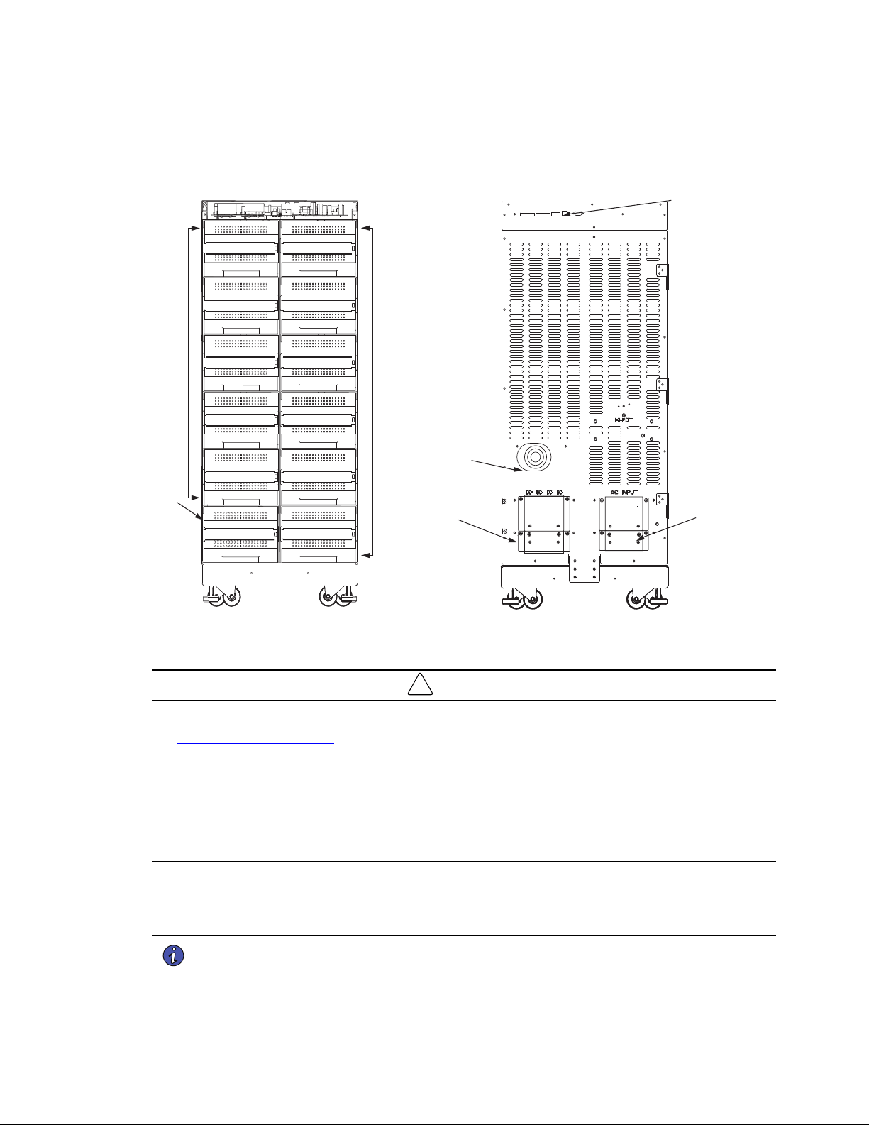
54 4–20kVA Users Guide P-164000669 4–20kVA Users Guide P-164000669—Rev 10
Figure 48. Connected EBM Front And Back
Super
Charger
Battery
Modules
Battery
Modules
EBM Front View
(Covers removed)
UPS DC
Terminal
Covers
DC Emergency
Disconnect
Switch
Communication
Ports
EBM
UPS AC
Terminal
Covers
EBM Front EBM Back
!
IMPORTANT
• The external battery cabinets are the same dimensions as the UPS cabinets. Refer to the ”
2.1 Preparing for Installation ” section for unpacking and cabinet setup.
• If you are installing multiple EBM(s) upstream to the UPS, repeat the setup as described in this section.
• The battery cables are supplied inside the battery cabinet accessory kit.
• In the UPS cabinet, the proper location of cabinet-to-cabinet DC wiring is on the lower left of the rear panel.
• All of the slots in the Standard 8 and 12 slot battery cabinets can be populated with batteries.
PPrreeppaarree tthhee EEBBMM CCaabbiinneett
1. Open the carton containing the external battery cabinet cable assembly and position it in the desired
location next to the UPS.
NOTE The UPS / EBM AC/DC terminal covers are shipped in the UPS and EBM accessory kit
and do not come installed on the UPS or EBM chassis.
Connected Battery Cabinet With Split Phase Input
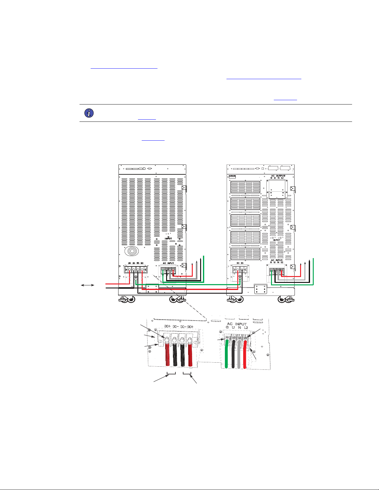
4–20kVA Users Guide P-164000669 4–20kVA Users Guide P-164000669—Rev 10 55
2. If you are rack-mounting the EBM cabinet, refer to the UPS rack-mount installation procedure (see
2.6 Rack-Mount Installation ). If not, proceed to the next step.
3. Install the anchor brackets to the floor if applicable (see 2.5 Anchor Bracket Installation ).
4. Push in the EBM DC emergency disconnect switch on the rear EBM panel and turn the switch lockout key.
5. Route the EBM DC input/output cables to the terminal blocks as shown in (Figure 49).
NOTE Torque the screws holding all input and output power conductors to the values specified
in Table 2 .
6. Connect the EBM DC Cables to the applicable terminals by removing and reinstalling the screws onto the
terminal blocks. See Figure 49.
Figure 49. Connected EBM ( Split Phase Input)
From previous
EBM
(if installed)
CN3CN4
CN4
EBM
UPS
DC+
DC-
DC+
DC-
L1
G
N
L2
N
L1
G
L2
Screws
Screws
Ground
Lug
Cover
DC+ DC- DC- DC+
G L1 N L2
To UPS
DC input cables from
upstream EBM
(if installed)
Terminal
Block
Terminal
Block
7. Reinstall the AC and DC terminal covers.
8. If additional battery cabinets are to be connected to the first, in a daisy-chain configuration, connect each
EBM with the DC cables supplied in the EBM accessory kit.
Connected Battery Cabinet With Split Phase Input

56 4–20kVA Users Guide P-164000669 4–20kVA Users Guide P-164000669—Rev 10
NOTE DC input cables only required if EBM(s) are installed upstream.
9. On the upper rear UPS and EBM panels, connect the input signal cables from the EBM CN4 to the UPS
input signal port CN4 using the supplied cables. (See Figure 50).
10. If additional battery cabinets are to be connected to the first, in a daisy-chain configuration, connect each
EBM with signal cables from CN3 to CN4 (see Figure 50 ).
Figure 50. UPS Input Control Signal Wiring (For External Controls)
EPO
(CN7)
To EBM(s)
UPS
ROO and On Generator
(CN6)
External CAN
(CN4)
To previous (upstream)
EBM CN4
Signal cables and
connectors (supplied)
EBM 1
EBM 2
CAN OUT
(CN3)
CAN OUT
(CN3)
CAN IN
(CN4)
CAN IN
(CN4)
11. Connect the CAN cable ground wires to the EBM chassis.
NOTE Connect each CAN ground wires to separate screws on the chassis. See Figure 51 .
Figure 51. Securing The CAN Ground Wire
Grey EBM CAN Communication Cable
2 17 117
CN3
CN4
CAN IN
CAN OUT
LAST EBM
JUMPER
NOT FOR CUSTOMER USE
RS-232
Secure Green and Yellow CAN
cable ground wire to the chassis
Green Terminal Jumper
in Last EBM
EBM 1
UPS
Secure Green and Yellow CAN
cable ground wire to the chassis
12. Close the DC emergency disconnect switch button on the back of each EBM. Insert the switch key
supplied with the cabinet into the button and turn clockwise 1/2-turn. Pull the button OUT to close the
switch and reconnect DC power. Turn the key back counter-clockwise, and remove the key (see Figure 52
).
Connected Battery Cabinet With Split Phase Input
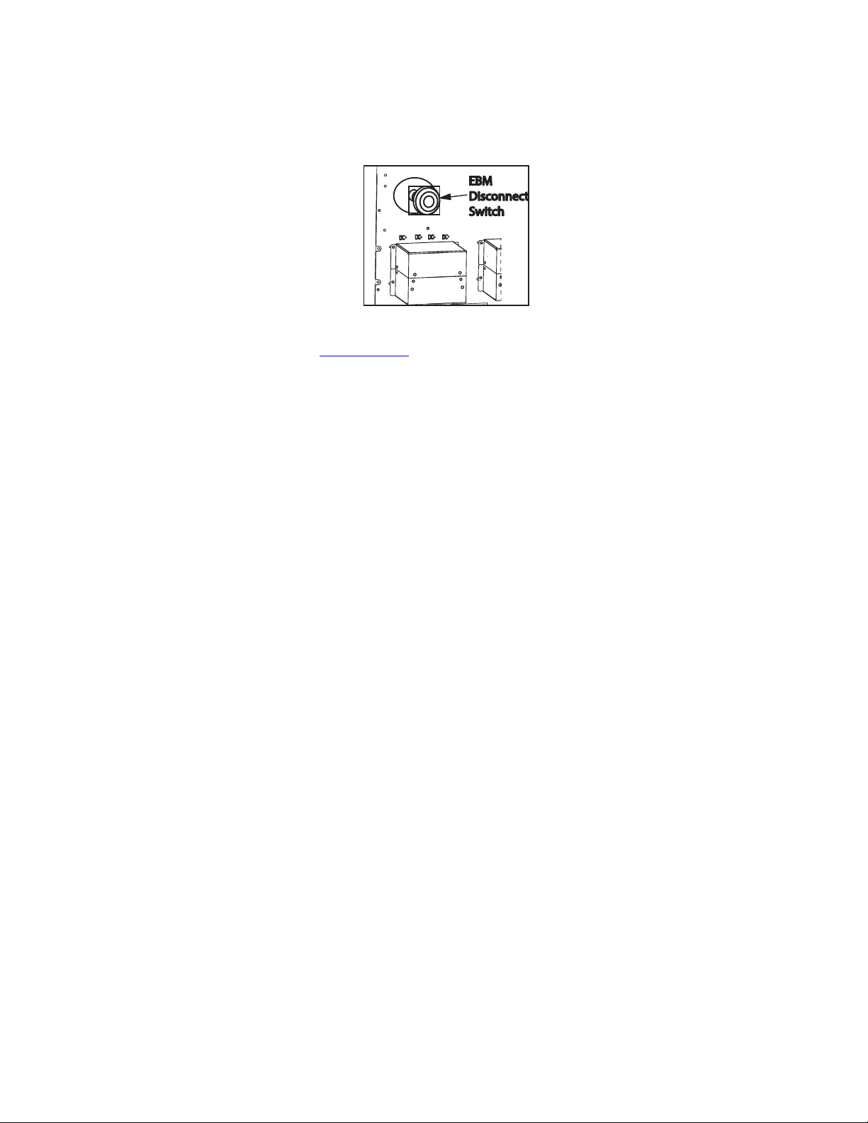
4–20kVA Users Guide P-164000669 4–20kVA Users Guide P-164000669—Rev 10 57
Figure 52. EBM Emergency Disconnect Switch
EBM
Disconnect
Switch
13. Proceed to Chapter 6.1 UPS Startup .
Connected Battery Cabinet With Split Phase Input

58 4–20kVA Users Guide P-164000669 4–20kVA Users Guide P-164000669—Rev 10
Connected Battery Cabinet With Split Phase Input

4–20kVA Users Guide P-164000669 4–20kVA Users Guide P-164000669—Rev 10 59
CChhaapptteerr 66 UUPPSS SSttaarrttuupp
66..11 UUPPSS SSttaarrttuupp
• This UPS contains its own energy source (batteries). The output receptacles may carry hazardous voltage
even when the UPS is not connected to an AC supply. When AC input voltage is present, the Eaton 9PXM
system can provide output voltage even though its batteries are disconnected. To confirm that there is no
UPS output voltage, always disconnect all of the AC input sources and unplug all two battery modules per
slot of internal batteries; if the UPS has one or more separate battery cabinets (EBMs), open (push in) the
DC emergency disconnect switch button on each battery cabinet or unplug two battery modules in each
slot of the battery cabinet.
• To reduce the risk of fire or electric shock, install this UPS in a temperature and humidity controlled, indoor
environment, free of conductive contaminants. Ambient temperature must not exceed 40°C (104°F). Do
not operate near water or excessive humidity (95% maximum).
• For optimum battery life, ambient temperature should not exceed 25°C (77°F). Battery life is substantially
reduced if ambient temperature is higher.
• Do NOT attempt to move the cabinet with the power or battery modules installed.
The UPS power modules (UPMs) are installed in the left hand slots of the UPS facing the user. Battery modules
are installed in the left or right hand slots (it takes two battery modules per slot to equal one battery string).
Removal of the power modules and battery modules is the reverse of these procedures.
Install the UPMs into the Eaton 9PXM cabinet: as follows:
1. Remove the front cover(s) of the cabinet. The covers have magnetic latches on the left and right sides that
hold them in place.
NOTE 1 Place battery modules beside all power modules in the UPS cabinet. Two battery
modules installed on top of each other are required for each battery slot and can be
removed separately.
NOTE 2 If you are installing a super charger module in the UPS, the super charger can be
installed in any of the left side slots. In the EBM, the super charger can only be installed
in the lower left side slot.
NOTE 3 The installation procedures of the optional battery cabinet (EBM) battery, and super
charger modules are identical to the UPS units.
NOTE 4 Battery modules are shipped fully charged. It is recommended to charge the batteries
for 48 hrs. after installation to ensure full power. If AC power fails before full battery
charge, backup will be available but for a reduced duration.
2. Insert the power modules into the left hand slots of the cabinet. Push each module firmly until it contacts
the connections in the rear of the slot.
3. Tighten the captive screw
4. To install the battery modules
• Slide the lower battery module fully into the slot until it contacts the connections in the rear of the slot.
• Repeat the procedure with the upper battery module.
• Install the retaining bracket and tighten the captive screw with a Phillips screwdriver.
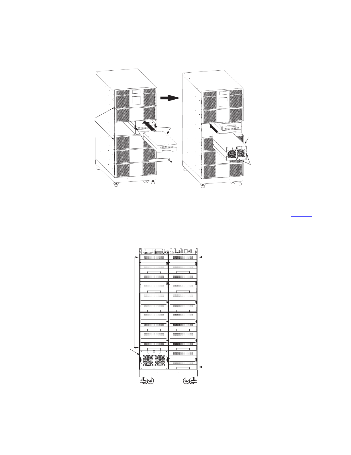
60 4–20kVA Users Guide P-164000669 4–20kVA Users Guide P-164000669—Rev 10
Figure 53. Inserting the Modules
Captive
Screws
Power
Module
Front
Covers (6)
Retaining
Bracket
Battery
Modules
Captive
Screw
5. If you installed the optional battery cabinets (EBMs), install the battery modules using the same procedure
as the UPS modules. If applicable, install the super charger in the lower left slot of the EBM. See Figure 54
.
Figure 54. EBM Battery Modules and Charger
Super
Charger
Battery
Modules
Battery
Modules
EBM Front View
(Covers removed)
UPS Startup
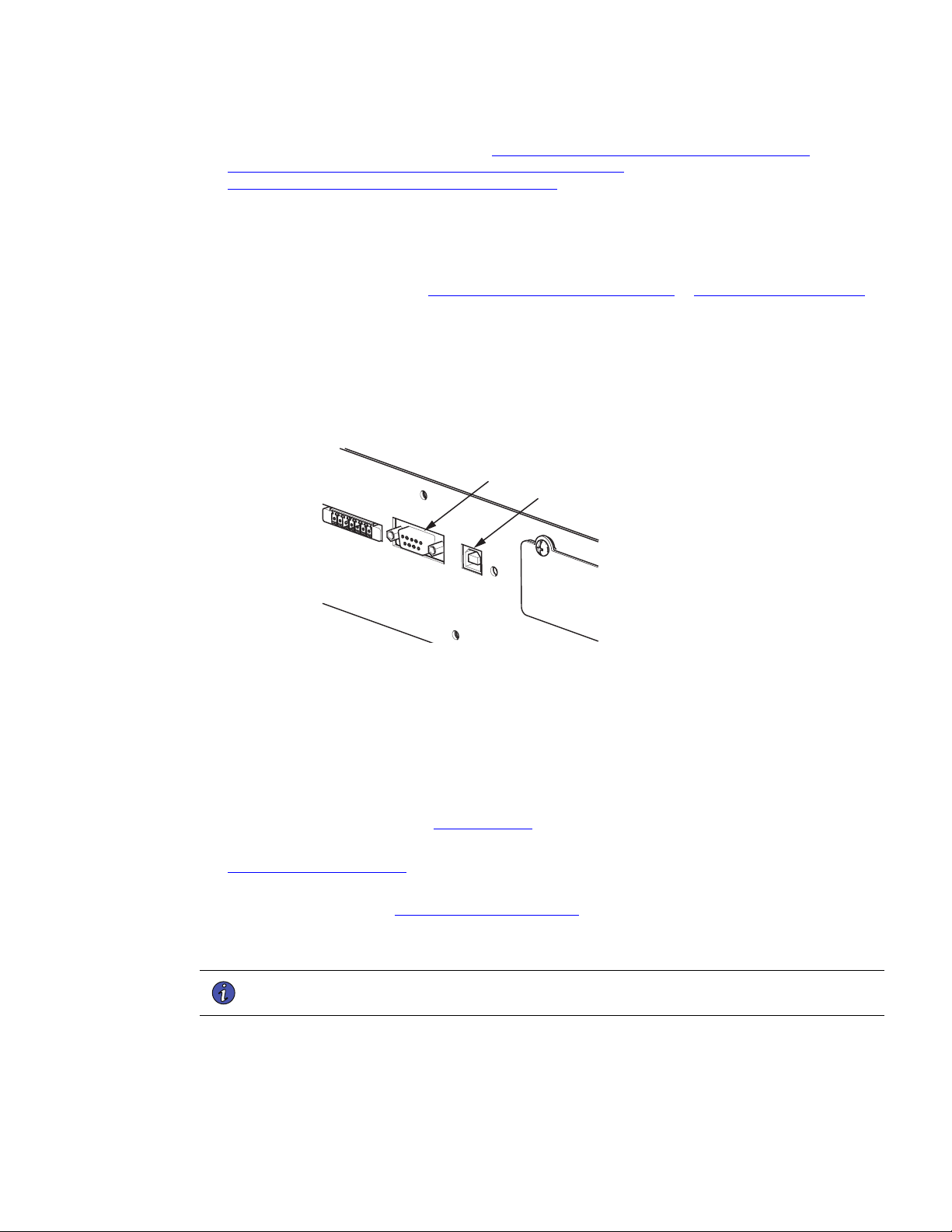
4–20kVA Users Guide P-164000669 4–20kVA Users Guide P-164000669—Rev 10 61
6. Replace the front covers and continue to “ 6.2 UPS Startup Without an External Bypass Switch,
6.3 Startup for Units Installed with an Eaton BPM Bypass Switch or
6.4 Startup for Units installed with a BPE Type Switch ”.
66..22 UUPPSS SSttaarrttuupp WWiitthhoouutt aann EExxtteerrnnaall BByyppaassss SSwwiittcchh
To start the UPS unit for the first time after installation:
1. If external battery cabinets (EBMs) are installed, check the cable connections between the UPS and
external battery cabinets (see , “5.2 Standard Battery Cabinet Installation or 5.1 Battery Cabinet Options ”).
2. Ensure that all power modules and battery modules are properly installed into the UPS cabinet.
3. If you are using power management software, connect your computer to either the DB9 or USB
communication ports on the top rear panel using the supplied communication cables.
Figure 55. Communication Ports
USB Port
(CN12)
DB9 Port
(CN17)
4. When starting the UPS, apply input power to the UPS by closing the service circuit breaker:
• If external battery cabinets are installed, close the DC emergency disconnect switch button on the
back of each external battery cabinet. Insert the switch key supplied with the cabinet into the button
and turn clockwise 1/2-turn. Pull the button out to close the switch. Turn the key back counter-
clockwise, and remove the key.
5. The UPS control panel display automatically turns on whenever input power is present and at least one
power module is installed (see , “6.1 UPS Startup ”).
6. Set up the initial operating parameters through the control panel display (see “
6.5 Initial Startup Parameters ” ).
7. If applicable, test proper operation of optional external control signals and computer communication before
connecting the load. (See “8.5 DB-9 Communication Port ” for details.)
8. If there are receptacles on the UPS rear panel, plug the equipment to be protected into the UPS output
receptacles.
NOTE DO NOT protect laser printers with the UPS because of the exceptionally high power
requirements of the heating elements.
9. Turn on the equipment that is connected to the UPS.
10. If there is an external bypass switch, ensure a proper phase check has been completed then turn the
switch to UPS. Otherwise, close the load distribution circuit breaker(s).
UPS Startup Without an External Bypass Switch

62 4–20kVA Users Guide P-164000669 4–20kVA Users Guide P-164000669—Rev 10
66..33 SSttaarrttuupp ffoorr UUnniittss IInnssttaalllleedd wwiitthh aann EEaattoonn BBPPMM BByyppaassss SSwwiittcchh
1. If your unit is wired to an external BPM bypass switch, you must perform a voltage and phase check
(Steps 2 through 1 ). Otherwise, skip to Step 1 .
Before operating the bypass switch, use the following procedure to check the wiring for correct installation. To
prevent damage to the load, turn off the main circuit breaker in the load service panel or verify that the load
cannot receive power from the UPS.
If the UPS is in the standby mode and the bypass switch is in the LINE or UPS positions pressing the
red bypass switch interlock button will energize the UPS output.
Do not attempt to push the red interlock button or attempt to move the bypass switch handle if the
UPS is operating on battery power.
2. At the bypass switch, press the red button and turn the switch to UPS.
3. Remove the six screws in the bypass switch front cover and remove the cover to gain access to the
terminal block for voltage measurements.
4. If external battery cabinets are installed, ensure that the battery cabinet is plugged into its external AC
source (if applicable) and close the DC emergency disconnect switch button on the back of each external
battery cabinet. Insert the switch key supplied with the cabinet into the button and turn clockwise 1/2-turn.
Pull the button out to close the switch. Turn the key back counter-clockwise, and remove the key.
5. The UPS front panel display automatically turns on whenever input power is present and at least one
power module is installed. Set up the initial operating parameters through the front panel display (see “
6.5 Initial Startup Parameters ” ).
6. Use an AC voltmeter to measure voltages on the terminal block inside the bypass switch cabinet. See
Figure 19 , which shows the terminal numbering for input and output UPS connections.
7. Record your measurements in the following chart. The voltages in the first column should be nearly equal
to the voltages in the second column. If the values differ by more than a few volts, check the terminal
block connections and correct any wiring problems.
AC Line Input Measurement AC from UPS Output Measurement
L1 to L2 (7 to 8*) 3 to 4*
N to L1 (6 to 7*) 2 to 3*
N to L2 (6 to 8*) 2 to 4*
8. Verify that the AC voltages from the UPS and the AC line input are in phase. Measure the voltage between
the following points on the terminal block and record in the spaces below. These measurements must be
no more than 20 Vac; if they are, call your service representative.
Terminal 3 (AC From UPS Output) To Terminal 7 (AC To UPS Input)
Terminal 4 (AC From UPS Output) To Terminal 8 (AC To UPS Input)
Startup for Units Installed with an Eaton BPM Bypass Switch

4–20kVA Users Guide P-164000669 4–20kVA Users Guide P-164000669—Rev 10 63
9. Measure the AC voltage between the following points on the terminal block and record in the space
below. This reading must be no more than 1 Vac; if it is, call your service representative.
Terminal 2 (AC From UPS Output) to 6 (AC Line Input)
10. Switch the bypass switch to LINE. Measure the voltage to the protected equipment (at the load
distribution panel) and verify that it is correct.
11. Switch the bypass switch to UPS and verify the voltage to the protected equipment is still correct.
12. Reinstall the bypass switch front cover and UPS front covers using the original screws.
13. If the UPS will not be operated immediately, switch the bypass switch to SERVICE and push in the DC
emergency disconnect switch button on the back panel of the external battery cabinet closest to the UPS.
Otherwise, continue to Step 14 to continue the UPS startup.
14. When starting the UPS, apply input power to the UPS by closing the service circuit breaker:
If external battery cabinets are installed, close the DC emergency disconnect switch button on the back of
each external battery cabinet. Insert the switch key supplied with the cabinet into the button and turn
clockwise 1/2-turn. Pull the button out to close the switch. Turn the key back counter-clockwise, and
remove the key.
15. The UPS front panel display automatically turns on whenever input power is present and at least one
power module is installed. Set up the initial operating parameters through the front panel display (see “
6.5 Initial Startup Parameters ” ).
16. If applicable, test proper operation of optional external control signals and computer communication before
connecting the load.
17. If there are receptacles on the UPS rear panel, plug the equipment to be protected into the UPS output
receptacles.
NOTE DO NOT protect laser printers with the UPS because of the exceptionally high power
requirements of the heating elements.
18. Turn on the equipment that is connected to the UPS.
19. If there is an external bypass switch, turn it to UPS. Otherwise, close the load distribution circuit breaker
(s).
66..44 SSttaarrttuupp ffoorr UUnniittss iinnssttaalllleedd wwiitthh aa BBPPEE TTyyppee SSwwiittcchh
1. If your unit is wired to an external bypass switch, you must perform a voltage and phase check (Steps 2
through 13). Otherwise, skip to Step 14.
Before operating the bypass switch, use the following procedure to check the wiring for correct installation. To
prevent damage to the load, turn off the main circuit breaker in the load service panel or verify that the load
cannot receive power from the UPS.
If the UPS is in the standby mode and the bypass switch is in the LINE or UPS positions pressing the
red bypass switch interlock button will energize the UPS output.
Do not attempt to push the red interlock button or attempt to move the bypass switch handle if the
UPS is operating on battery power.
2. At the bypass switch, press the red button and turn the switch to UPS.
Startup for Units installed with a BPE Type Switch

64 4–20kVA Users Guide P-164000669 4–20kVA Users Guide P-164000669—Rev 10
3. Remove the six screws in the bypass switch front cover and remove the cover to gain access to the
terminal block for voltage measurements.
4. If external battery cabinets are installed, ensure that the battery cabinet is plugged into its external AC
source (if applicable) and close the DC emergency disconnect switch button on the back of each external
battery cabinet. Insert the switch key supplied with the cabinet into the button and turn clockwise 1/2-turn.
Pull the button out to close the switch. Turn the key back counter-clockwise, and remove the key.
5. The UPS front panel display automatically turns on whenever input power is present and at least one
power module is installed. Set up the initial operating parameters through the front panel display (see “
6.5 Initial Startup Parameters ” ).
6. Use an AC voltmeter to measure voltages on the terminal block inside the bypass switch cabinet. See
Figure 19 , which shows the terminal numbering for input and output UPS connections.
7. Record your measurements in the following chart. The voltages in the first column should be nearly equal
to the voltages in the second column. If the values differ by more than a few volts, check the terminal
block connections and correct any wiring problems.
AC Line input Measurement AC from UPS Output Measurement
L1 to L2 (11 to 12*) 7 to 8*
N to L1 (10 to 11*) 6 to 7*
N to L2 (10 to 12*) 6 to 8*
* For some installations, there is no connection at terminals 6, 8, 10, or 12.
8. Determine what type of bypass switch you are using:
If the bypass switch is a Break-Before-Make type, skip this step and proceed to Step 13.
If the bypass switch is a Make-Before-Break type, verify that the AC voltages from the UPS and the AC line
input are in phase. Measure the voltage between the following points on the terminal block and record in
the spaces below. These measurements must be no more than 20 Vac; if they are, call your service
representative.
Terminal 7 to 11
Terminal 8 to 12
9. Measure the AC voltage between the following points on the terminal block and record in the space
below. This reading must be no more than 1 Vac; if it is, call your service representative.
Terminal 6 to 10
10. Switch the bypass switch to LINE. Measure the voltage to the protected equipment (at the load
distribution panel) and verify that it is correct.
11. Switch the bypass switch to UPS and verify the voltage to the protected equipment is still correct.
12. Reinstall the bypass switch front cover and UPS front covers using the original screws.
13. If the UPS will not be operated immediately, switch the bypass switch to SERVICE and push in the DC
emergency disconnect switch button on the back panel of the external battery cabinet closest to the UPS.
Otherwise, continue to Step 14.
Startup for Units installed with a BPE Type Switch

4–20kVA Users Guide P-164000669 4–20kVA Users Guide P-164000669—Rev 10 65
14. When starting the UPS, apply input power to the UPS by closing the service circuit breaker: l If external
battery cabinets are installed, close the DC emergency disconnect switch button on the back of each
external battery cabinet. Insert the switch key supplied with the cabinet into the button and turn clockwise
1/2-turn. Pull the button out to close the switch. Turn the key back counter-clockwise, and remove the key.
15. The UPS front panel display automatically turns on whenever input power is present and at least one
power module is installed. Set up the initial operating parameters through the front panel display (see “
6.5 Initial Startup Parameters ” ).
16. If applicable, test proper operation of optional external control signals and computer communication before
connecting the load.
17. If there are receptacles on the UPS rear panel, plug the equipment to be protected into the UPS output
receptacles.
NOTE DO NOT protect laser printers with the UPS because of the exceptionally high power
requirements of the heating elements.
18. Turn on the equipment that is connected to the UPS.
19. If there is an external bypass switch, turn it to UPS. Otherwise, close the load distribution circuit breaker
(s).
66..55 IInniittiiaall SSttaarrttuupp PPaarraammeetteerrss
The first time the UPS is turned on, you must set or verify certain operating parameters before placing the UPS
into operation. To set these initial configuration parameters:
1. After the Eaton® logo screen appears, select the desired language for the display. Use the and buttons to
scroll between English, French, and Spanish. Enter your selection by pressing the button.
Language
English √
Françias
Español
2. Select the desired UPS output voltage using the and buttons. Possible selections are 100/200,110/
220,120/208, 120/240, 127/220 Vac. Press the
button when the desired output value is displayed.
3. Set the clock for the local time and date.
• If the time or the date is correct as displayed, press the button to advance to the next configuration
setting. Time must be entered in 24-hour format.
• If the time is incorrect as displayed, select the desired format and press the <- and -> buttons to move
left and right. Press the
and buttons to increase or decrease the value of each selected digit.
When the displayed value is correct, press the button.
Initial Startup Parameters
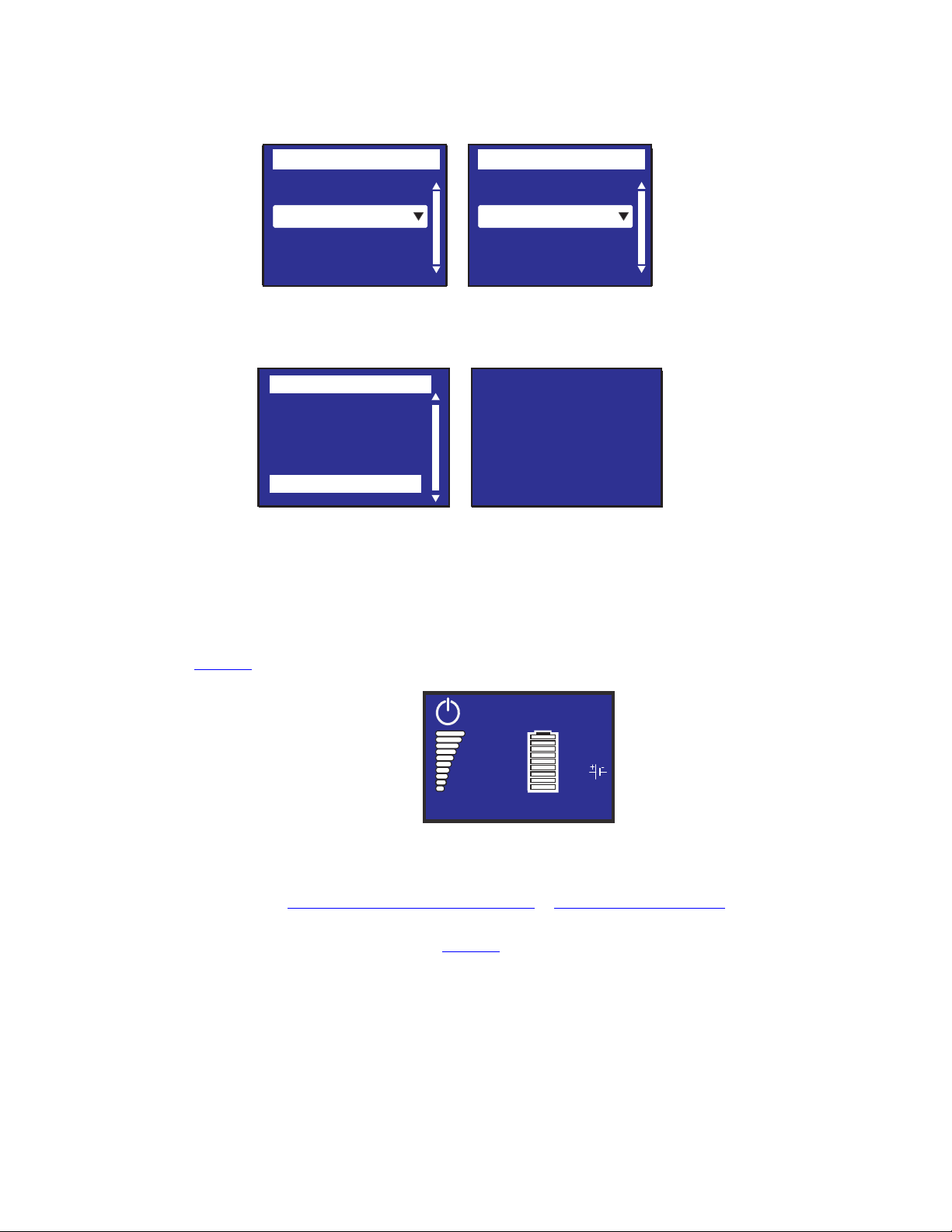
66 4–20kVA Users Guide P-164000669 4–20kVA Users Guide P-164000669—Rev 10
Date / Time
International
Format :
23/05/2020 15 :05
Date / Time
MM/DD/YYYY US
Format :
02/05/2020 03 :05
Date / Time
International
Format :
23/05/2020 15 :05
Date / Time
MM/DD/YYYY US
Format :
02/05/2020 03 :05
Settings
Event Log
Fault Log
Identification
Register Product
Menu
Please register at:
www.eaton.com
Type
Eaton...9PXM
Date / Time
International
Format :
23/05/2020 15 :05
Date / Time
MM/DD/YYYY US
Format :
02/05/2020 03 :05
4. Select 'Register product' from the menu and register your product with Eaton.
Date / Time
International
Format :
23/05/2020 15 :05
Date / Time
MM/DD/YYYY US
Format :
02/05/2020 03 :05
Date / Time
International
Format :
23/05/2020 15 :05
Date / Time
MM/DD/YYYY US
Format :
02/05/2020 03 :05
Settings
Event Log
Fault Log
Identification
Register Product
Menu
Please register at:
www.eaton.com
Type
Eaton...9PXM
5. The system signals an alarm when the required output cannot be maintained with the loss of redundant
power modules. The alarm is essentially disabled with a redundancy level set at 0.
6. Optional. If you want the system to notify you when the number of redundant power modules is less than
a specified level, enter a redundancy level. Each increment above 0 indicates the number of modules that
can be removed from operation before the alarm occurs. This setting affects only the alarm; the system
continues to operate as an N+X system even if this parameter is left at the default value of 0 (see also
Figure 64 ).
Efficiency: 94%
100%
10.1kW
10.1kV
100%
19min
24
Load not powered
7. If you have a “Standard” Eaton 9PXM battery cabinet or a “Connected” No AC battery cabinet option
installed navigate to the battery settings menu and set the number of external battery strings that you have
installed. See “5.2 Standard Battery Cabinet Installation or 5.1 Battery Cabinet Options “
8. The UPS is now ready to operate, and displays the normal On/Off function screen. Press the ON button on
the display screen to start the UPS. See Figure 56 .
Initial Startup Parameters

4–20kVA Users Guide P-164000669 4–20kVA Users Guide P-164000669—Rev 10 67
CChhaapptteerr 77 OOppeerraattiioonn
77..11 NNoorrmmaall OOppeerraattiioonn
To operate the UPS:
1. Verify the UPS startup procedure has been completed (see , “6.1 UPS Startup ” )
2. The UPS control panel display illuminates and shows the EATON logo. See “ Figure 59 ”.
3. Verify that the power-on symbol
shows on the UPS status screen.
4. Press the
button on the UPS front panel until a beep sounds.
5. Check the UPS front panel display for active alarms or notices. Resolve any active alarms before
continuing. See , “11.1 Troubleshooting ”. If the
indicator is on, do not proceed until all alarms are
clear. Check the UPS status from the front panel to view the active alarms. Correct the alarms and restart if
necessary.
6. Verify that the
indicator illuminates solid, indicating that the UPS is operating normally and any loads
are powered and protected.
7. Make sure the UPS is in Online mode.
77..22 UUPPSS SSttaannddbbyy MMooddee
To place the UPS in standby:
Press the
button on the front panel for three seconds.
• The UPS starts to beep then transfers to Standby mode.
• The
indicator will flash continually.
77..33 UUPPSS SShhuuttddoowwnn
Observe all Lock-Out / Tag-Out procedures when external power is removed.
To shutdown the UPS completely:
• Place the UPS in standby
• Remove AC power by opening the building service circuit breaker or placing the bypass switch in SERVICE
(if installed). Remove DC power by pressing the DC disconnect switch on the back of the EBM(s) and
removing all battery modules from the UPS cabinet.
77..44 OOppeerraattiinngg MMooddeess
77..44..11 OOnnlliinnee MMooddee
The Eaton 9PXM front panel indicates the UPS status through the UPS indicators, see page 11.
Online Mode
During Online mode, the indicator illuminates solid and the UPS is powered from the utility. The UPS
monitors and charges the batteries as needed and provides filtered power protection to your equipment.

68 4–20kVA Users Guide P-164000669 4–20kVA Users Guide P-164000669—Rev 10
77..44..22 BBaatttteerryy MMooddee
Battery Mode
When the UPS is operating during a power outage, the alarm beeps once every ten seconds and the indicator
illuminates solid. The necessary energy is provided by the battery. When the utility power returns, the UPS
transfers to Online mode operation while the battery recharges.
Low-Battery Warning
If the low battery warning occurs, shutdown all applications on the connected equipment because automatic
UPS shutdown is imminent.
If battery capacity becomes low while on Battery mode:
• The
indicator illuminates solid.
• The audible alarm beeps once every 3 seconds. (This warning is approximate, and the actual time to
shutdown may vary significantly.)
• After the UPS shuts down the UPS automatically restarts when utility power is restored (if Auto Restart is
enabled).
End of Battery Backup Time
• All the LEDs go OFF.
• The audio alarms stops.
77..44..33 LLooww BBaatttteerryy WWaarrnniinngg
During discharge, the low battery alarm is activated if the remaining runtime goes below 3 minutes or less than
the setting capacity threshold (0% by default). This threshold can be modified.
77..44..44 BByyppaassss MMooddee
Bypass Mode
In the event of a UPS overload or internal failure, the UPS transfers your equipment to utility power. Battery
mode is not available and your equipment is not protected; however, the utility power continues to be passively
filtered by the UPS. The
indicator illuminates. Depending on overload conditions, the UPS remains in
Bypass mode for at least 5 seconds and will stay in this mode if three transfers to bypass occur within one
hour.
The UPS transfers to Bypass mode when:
• User or Service activates Bypass mode through the front panel LCD or by using an external bypass switch
(BPM or BPE).
• Overload between 105 and 110% for more than 30 seconds
• Overload above 115% for more than 200 msecs
• Output Short
• Hardware fault
• Over Temperature on heatsinks
Operating Modes

4–20kVA Users Guide P-164000669 4–20kVA Users Guide P-164000669—Rev 10 69
NOTE 1 NOTE Load imbalance between UPMs is <5%
NOTE 2 NOTE The UPS shuts down after a specified delay for overload conditions listed above.
77..55 RReettuurrnn ooff AACC IInnppuutt PPoowweerr
Following an outage, the UPS restarts automatically when AC input power returns (unless the auto restart
function has been disabled) and the load is supplied again.
Setting High Efficiency Mode
In High Efficiency mode, the UPS transfers to Online (or Battery) mode in less than 10 ms when utility fails.
Transfers to High Efficiency mode will be active after 5 minutes of Bypass voltage monitoring: if Bypass quality
is not in tolerance, then the UPS will remain in Online mode.
To set the High Efficiency mode:
1. Select Settings, In/Out settings, and High Efficiency mode (see Figure 64 ).
2. Select Enabled and Enter to confirm.
3. The UPS transfers to High Efficiency mode after 5 minutes.
NOTE If the input is not stable after enabling HE Mode, the UPS will monitor the input for 5
minutes but if it is stable to begin with, it will transfer immediately.
77..66 CCoonnffiigguurriinngg BByyppaassss SSeettttiinnggss
The following settings are available for configuring Bypass operation (see Figure 64 ).
Changing the Bypass settings changes UPS behavior and may result in decreased protection.
Bypass Voltage Min Limit
The default disables a transfer to Bypass if the measured bypass voltage level is below the nominal output
voltage -12%. You can configure the setting for another voltage value. This setting can be overruled by the
“Protected Bypass” setting.
Bypass Voltage Max Limit
The default disables a transfer to Bypass if the measured bypass voltage level is above the nominal output
voltage +12%. You can configure the setting for another voltage value. This setting can be overruled by the
“Protected Bypass” setting.
Protected Bypass (Enabled)
Allows a transfer to Bypass only when Bypass is within the following specifications:
• Bypass voltage is between the “Bypass Voltage Low Limit” and “Bypass Voltage High Limit” settings
• Bypass frequency is within 5% of nominal frequency.
Unsynchronized Transfers
When Qualify Bypass is set to “Always” or “Always on Fault” you can select the interruption time when
transferring to bypass, default setting is “Half Cycle” but can be changed to “Full cycle”.
Return of AC Input Power

70 4–20kVA Users Guide P-164000669 4–20kVA Users Guide P-164000669—Rev 10
77..77 CCoonnffiigguurriinngg BBaatttteerryy SSeettttiinnggss
The following battery settings enable battery tests, alarms and enable auto mode and (see Figure 66 ).
77..77..11 AAddvvaanncceedd BBaatttteerryy MMaannaaggeemmeenntt
Advanced Battery Management (ABM) extends the life of the battery by shutting off the charger for 28 days
per ABM cycle and therefore reduces grid corrosion in the battery caused by trickle charging over long periods
of time. Disabling ABM means the battery chargers run in constant charge mode and never turn off. The
battery test period is every three ABM cycles.
NOTE It is not recommended to perform a battery discharge test more often than 90 days.
77..77..22 AAuuttoo BBaatttteerryy TTeesstt
The battery test will run only in Rest Mode and if ABM is enabled. The tests frequency can be modified. During
the test, the UPS transfers to Battery mode and discharges the batteries for 25% battery time remaining.
NOTE Battery mode is not displayed and battery low alarm does not activate during a battery
test.
The battery test may be postponed due to bad conditions, or failed if battery is not ok.
77..77..33 LLooww BBaatttteerryy WWaarrnniinngg
During discharge, the low battery alarm is activated if the remaining runtime goes below 3 minutes or less than
the setting capacity threshold (0% by default). This threshold can be modified.
77..77..44 EExxtteerrnnaall BBaatttteerryy SSeettttiinngg
The number of Extended Battery Module is automatically detected, or can be set manually in number of EBM
or in Ah.
77..77..55 DDeeeepp DDiisscchhaarrggee PPrrootteeccttiioonn
This setting is recommended to avoid damaging the battery. Warranty is void if deep discharge protection is
disabled
77..88 RReettrriieevviinngg tthhee EEvveenntt LLoogg
To retrieve the Event log through the display:
1. Press any button to activate the menu options, then select Event log (see Figure 70 ).
2. Scroll through the listed events.
3. Reset event log if desired.
77..99 RReettrriieevviinngg tthhee FFaauulltt LLoogg
To retrieve the Fault log through the display:
1. Press any button to activate the menu options, then select Fault log (see Figure 71 ).
2. Scroll through the listed faults.
3. Reset fault log if desired.
77..1100 CCoonnttrrooll PPaanneell OOppeerraattiioonn
The control panel provides UPS function and control settings.
Configuring Battery Settings
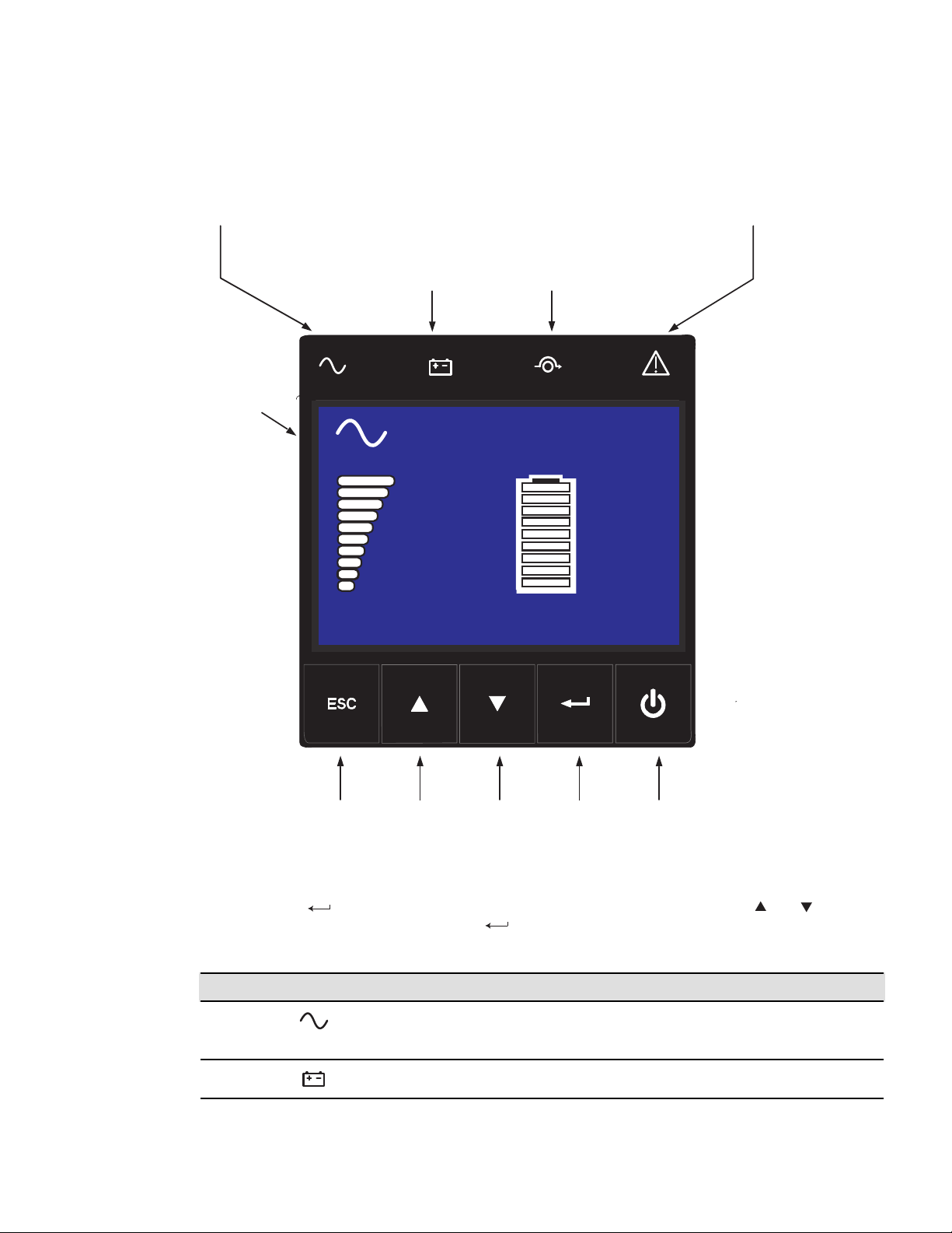
4–20kVA Users Guide P-164000669 4–20kVA Users Guide P-164000669—Rev 10 71
Figure 56. UPS Control Panel
Online mode
Battery mode
indicator (orange)
Online mode
indicator (green)
Bypass mode
indicator (orange)
Fault
indicator (red)
Escape Up Down Enter On/Off
button
LCD
Screen
Online mode
100%
19min
1EBM
100%
2.7kW
3.0kVA
Efficiency: 94 %
Efficiency: 94%
100%
2.7kW
3.0kVA
100%
19min
1EBM
Online mode
77..1111 DDiissppllaayy FFuunnccttiioonnss
Press the Enter ( ) button to activate the menu options. Use the two middle buttons ( and ) to scroll
through the menu structure. Press the Enter (
) button to select an option. Press the ESC button to cancel
or return to the previous menu (see Figure 49).
Indicator Status Description
Green
On The UPS is operating normally on Online
or High Efficiency mode.
On The UPS is on Battery mode
Display Functions
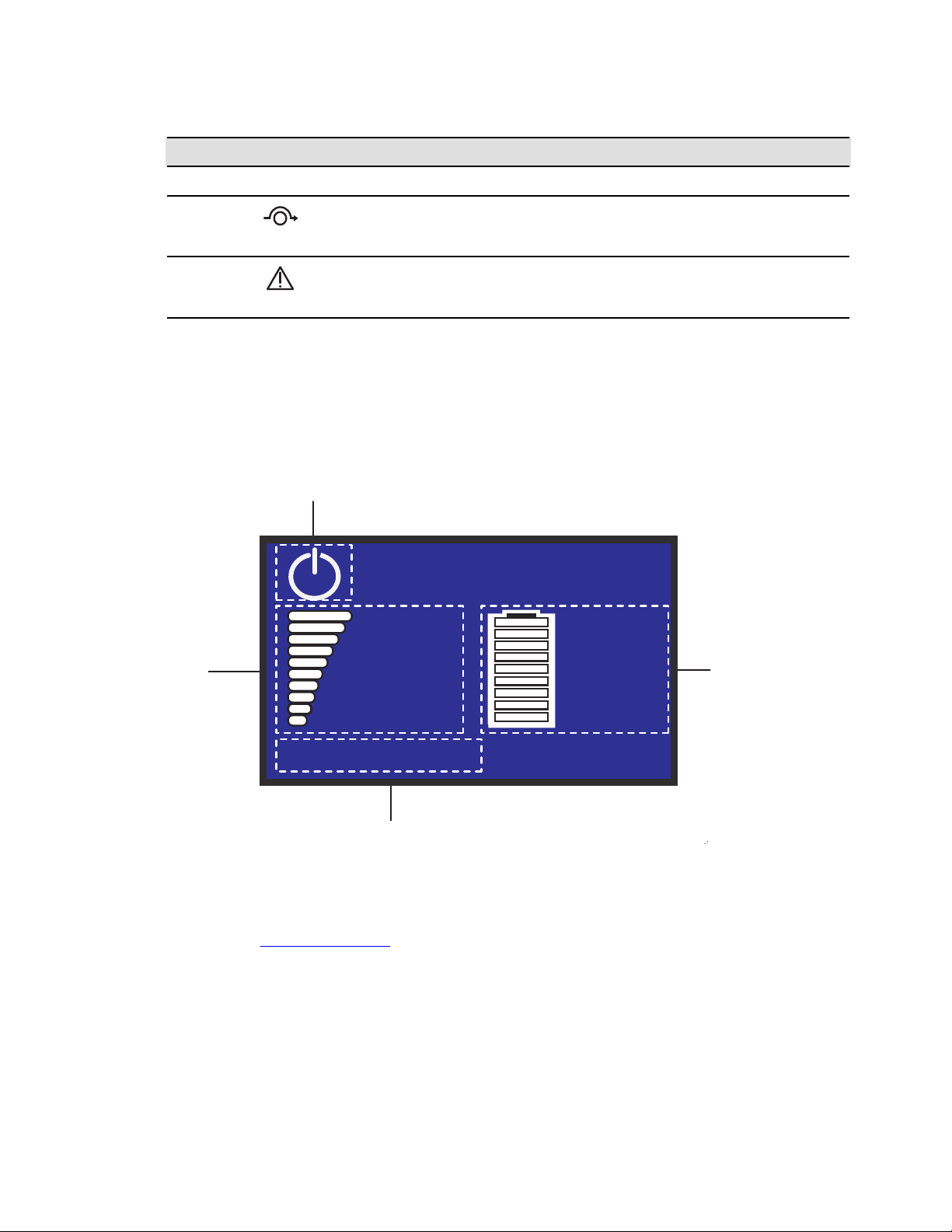
72 4–20kVA Users Guide P-164000669 4–20kVA Users Guide P-164000669—Rev 10
Indicator Status Description
Orange
Bypass
On The UPS is on Bypass mode.
Red
On The UPS has an active alarm or fault. See
Chapter 11, “Troubleshooting” for
additional information.
77..1122 LLCCDD DDeessccrriippttiioonn
After five minutes of inactivity, the LCD displays the screen saver.
The LCD backlight automatically dims after 10 minutes of inactivity. Press any button to restore the screen.
Figure 57. LCD Display Status Indicators
Operation status
Load/equipment
status
Efficiency and load group information
Battery status
Efficiency: 94%
100%
2.7kW
3.0kVA
100%
19min
1EBM
Online mode
77..1133 DDiissppllaayy SSttaattuuss IInnddiiccaattoorrss
The following table describes the status information provided by the UPS If another indicator not shown
appears, see, “11.1 Troubleshooting ” for additional information.
LCD Description
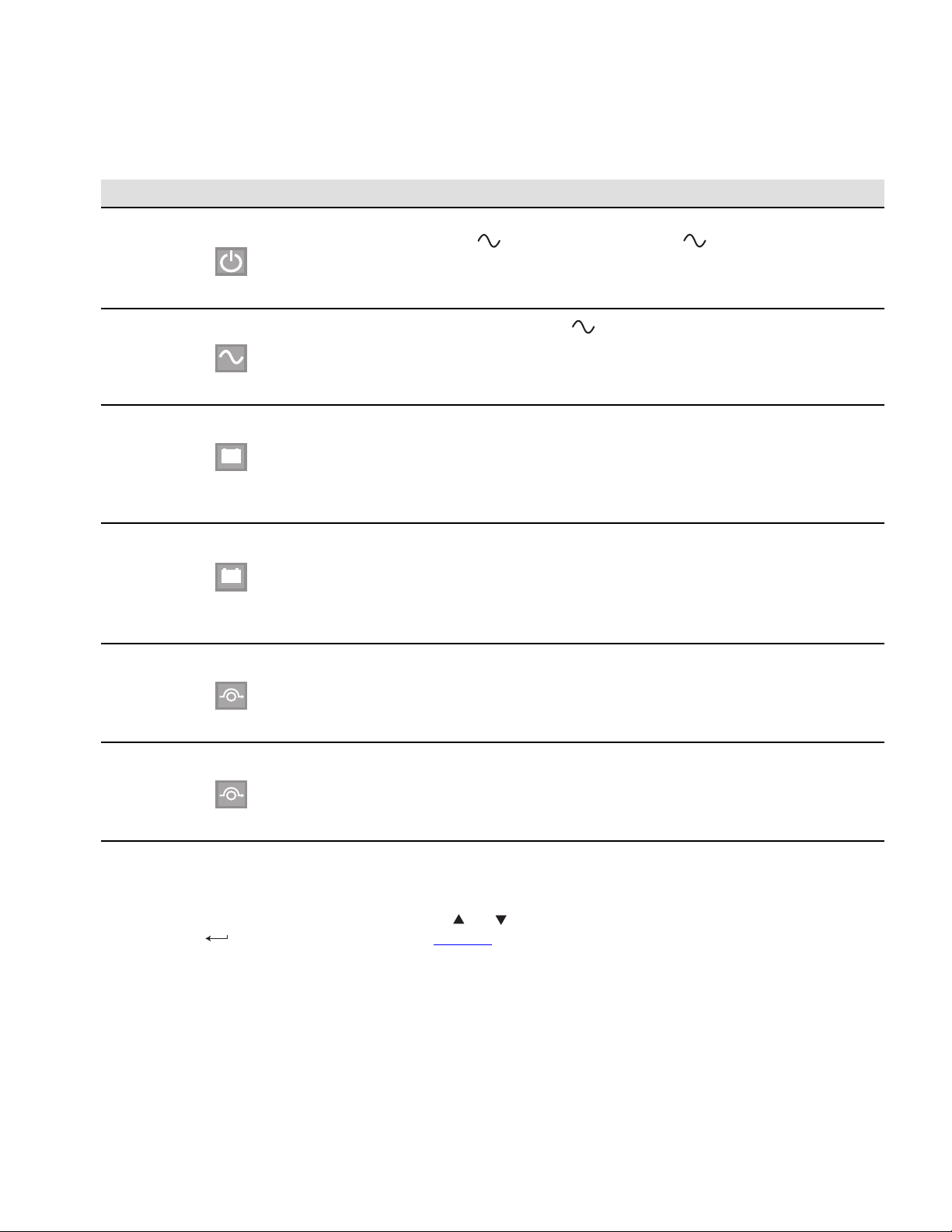
4–20kVA Users Guide P-164000669 4–20kVA Users Guide P-164000669—Rev 10 73
Figure 58. Display Status Indicators
Indicator Status Description
Standby Mode
The UPS is Off, waiting for startup command
from user. The
indicator flashes
continually.
Equipment is not powered until button is
pressed.
Green LED blinking when UPS is
in Standby mode.
Online Mode
The UPS is operating normally. The
indicator is on steady.
The UPS is powering and protecting the
equipment.
Battery Mode
+
-
1 beep every 10 seconds
A utility failure has occurred and the UPS is on
Battery mode.
The UPS is powering the equipment with the
battery power.
Prepare your equipment for shutdown.
End of Backup Time
+
-
1 beep every 3 seconds
The UPS is on Battery mode and the battery is
running low.
Low Battery Warning settings: [Capacity] [0%]...
[100%]
[Runtime] [0mn]...[60mn]
The alarm triggers when the set percentage of
battery
capacity or remaining back-up time is reached.
High Efficiency Mode
The UPS is operating on High Efficiency mode. The UPS is powering and protecting the
equipment
Bypass Mode
An overload or a fault has occurred, or a
command has been received, and the UPS is in
Bypass mode.
Equipment is powered but not protected by the
UPS.
77..1144 CChhaannggiinngg PPaarraammeetteerr SSeettttiinnggss
The LCD display menus can be selected to show measurements, change control settings and show UPS and
event logs. Use the two middle buttons (
and ) to scroll through the menu screens then press the Enter (
) button to select an option (see Figure 60 ).
77..1155 DDiissppllaayy MMeennuu SSccrreeeennss
SSttaarrtt SSccrreeeenn
The start screen shows the required information at first startup.
Changing Parameter Settings
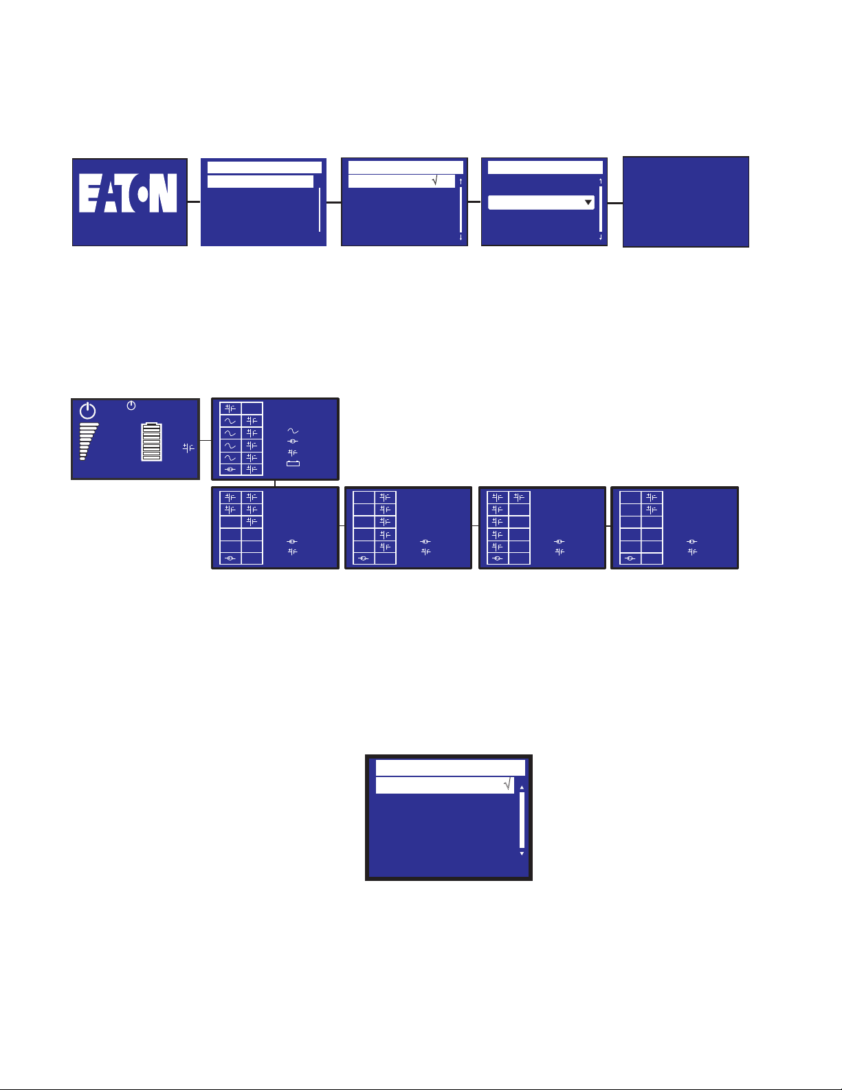
74 4–20kVA Users Guide P-164000669 4–20kVA Users Guide P-164000669—Rev 10
Figure 59. Start Screen
Language
English
√
Françias
Español
Output voltage
110 V
√
120 V
127 V
Date / Time
International
Format :
23/05/2020 15 :05
Please register at:
www.eaton.com
Type
Eaton...9PXM
Start Screen
SSttaattuuss SSccrreeeenn
The status screen shows the status of the installed units.
Figure 60. Status Screen Menu
UPS
4
1
6
4
EBM
EBM 1
1
5
EBM 2
1
5
EBM 3
1
6
EBM 4
1
2
Efficiency: 94%
100%
10.1kW
10.1kV
100%
19min
24
Press to start
MMeennuu SSccrreeeenn
The Menu Screen selects and controls system features and operating conditions (see Figure 54). Menu items
include:
The Menu screen is the main menu and shows the available sub-menus.
Menu
Measurements √
Control
Settings
Event Log
Identification
Register Product
Display Menu Screens
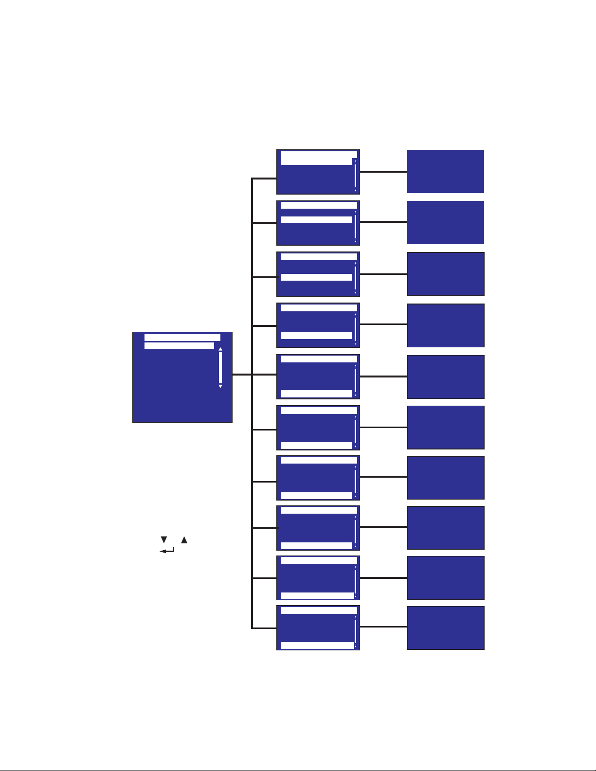
4–20kVA Users Guide P-164000669 4–20kVA Users Guide P-164000669—Rev 10 75
MMeeaassuurreemmeennttss
The Measurements screen shows the measurements of the installed units.
Figure 61. Measurements Menu
Measurements
Total Load
Load Phase 1 (N-L1)
Load Phase 2 (N-L2)
Input
Bypass
Measurements
Total Load
Load Phase 1 (N-L1)
Load Phase 2 (N-L2)
Input
Bypass
Measurements
Total Load
Load Phase 1 (N-L1)
Load Phase 2 (N-L2)
Input
Bypass
Measurements
Total Load
Load Phase 1 (N-L1)
Load Phase 2 (N-L2)
Input
Bypass
Measurements
Bypass
Load Phase 1 (N-L1)
Load Phase 2 (N-L2)
Input
Total Output
Total Load
Load Phase 1 (N-L1)
Load Phase 2 (N-L2)
Input
Bypass
Total Output
Output / Efficiency
Battery
Average Power Usage
Cumulat. Power Usage
Measurements
Measurements
Total Load
Load Phase 1 (N-L1)
Load Phase 2 (N-L2)
Input
Bypass
Measurements
Total Output
Load Phase 2 (N-L2)
Input
Bypass
Output / Efficiency
Measurements
Output / Efficiency
Input
Bypass
Total Output
Battery
Measurements
Battery
Bypass
Total Output
Output / Efficiency
Average power usage
Measurements
Average power usage
Total Output
Output / Efficiency
Battery
Cumulat. power usage
Total Load
0W 0.0A
0VA 0.00pf
Load Phase 1 (N-L1)
0W 0.0A
0VA 0.00pf
0
W
0.0A
0
VA
0.00pf
Input
122
V1
122
V2
60.00
Hz
Average Power Usage
0
Wh
Cumulat. power usage
0
kWh
Since:
01/01/2000 00.00
Load Phase 2 (N-L2)
Bypass
122
V1
122
V2
60.00
Hz
Total Output
206V 59.0Hz
N-L1 N-L2
119V 119V
Efficiency
- - %
Battery
96% 999min
ABM Charging
138v
*Output readings
for example only
On control panel:
Press ( ) or ( ) to scroll menu
Press ( ) button to select
Press ESC for previous screen
Display Menu Screens
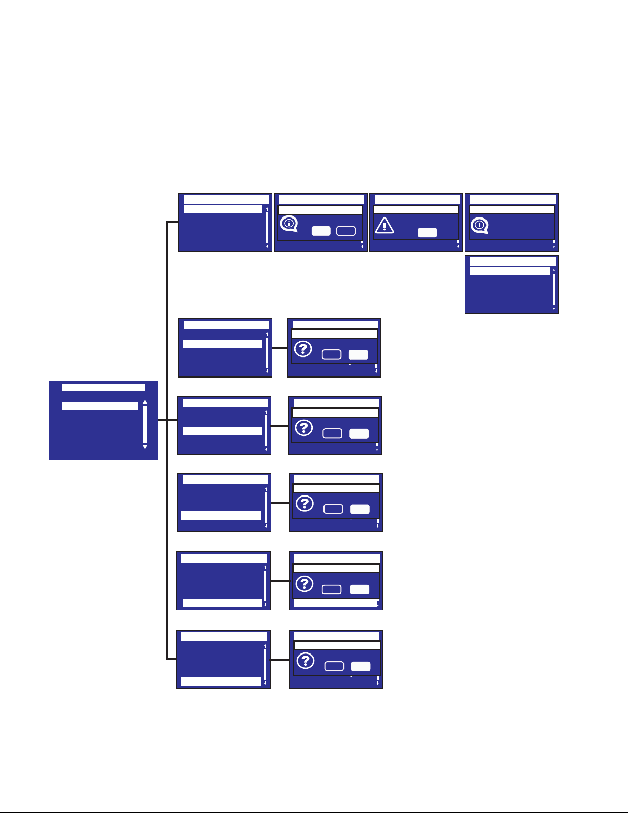
76 4–20kVA Users Guide P-164000669 4–20kVA Users Guide P-164000669—Rev 10
CCoonnttrrooll
The Control menu provides bypass control and reset of some fault and factory settings.
Figure 62. Control Menu
Control
Measurements
Settings
Event Log
Fault Log
Identification
Register Product
Control
Control
Go to bypass
Start battery test
Reset fault state
Restore factory set
Reset average power
Control
Go to bypass
Start battery test
Reset fault state
Restore factory set
Reset average power
Control
Go to bypass
Start battery test
Reset fault state
Restore factory set
Reset average power
Control
Go to bypass
Start battery test
Reset fault state
Restore factory set
Reset average power
Control
Go back normal
Start battery test
Reset fault state
Restore factory set
Reset average power
Control
Go to bypass
Start battery test
Reset fault state
Restore factory set
Reset average power
Control
Go to bypass
Start battery test
Reset fault state
Restore factory set
Reset average power
Control
Go to bypass
Start battery test
Reset fault state
Restore factory set
Reset average power
Control
Go to bypass
Start battery test
Reset fault state
Restore factory set
Reset average power
Control
Reset Cumul.power
Start battery test
Reset fault state
Restore factory set
Reset average power
Control
Go to bypass
Start battery test
Reset fault state
Restore factory set
Reset average power
Control
Go to bypass
Start battery test
Reset fault state
Restore factory set
Reset average power
Control
Go to bypass
Start battery test
Reset fault state
Restore factory set
Reset average power
Control
Go to bypass
Start battery test
Reset fault state
Restore factory set
Reset average power
Control
Go to bypass
Start battery test
Reset fault state
Restore factory set
Reset average power
Go to bypass
Ye s
No
Are you sure?
Alarm
OK
Para redund.
lost
Go to bypass
Done
Start battery test
No
Ye s
Are you sure?
Reset fault state
No
Ye s
Are you sure?
Restore factory set
No
Ye s
Are you sure?
Reset average power
No
Ye s
Are you sure?
Reset cumul. power
No
Ye s
Are you sure?
Display Menu Screens
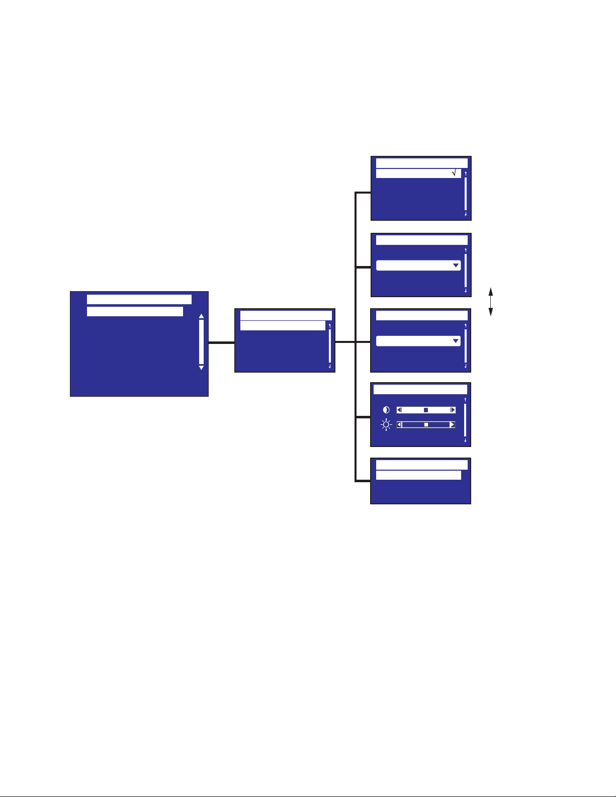
4–20kVA Users Guide P-164000669 4–20kVA Users Guide P-164000669—Rev 10 77
LLooccaall SSeettttiinnggss
The Settings menus allow the user to modify UPS settings.
Figure 63. Local Setting Menu
Date / Time
International
Format :
23/05/2020 15 :05
Date / Time
MM/DD/YYYY US
Format :
02/05/2020 03 :05
Language
English √
Françias
Español
Local Settings
In/Out settings
On/Off settings
Battery settings
Input signals
Comm settings
User password enable
User password settings
Settings
Local settings
Language
Date/time
LCD
Audible alarm
LCD settings
Audible alarm
Enabled √
Disable on battery
Always disabled
[English] [Français]
[Espanol] Menus, status,
notices and alarms, UPS fault,
Event Log data and
settings are in all
supported languages.
Format: [International] [US]
Set Time to
International
format
Drop down menu
to select format
Set Time to
US format
Modify LCD Modify LCD
screen brightness and
contrast to be adapted
to room light conditions
Mode: [Enabled][Disabled
on battery][Always disabled]
Enable or alwaysdisable the
buzzer if an alarm occurs.
Select Local User Settings
Display Menu Screens
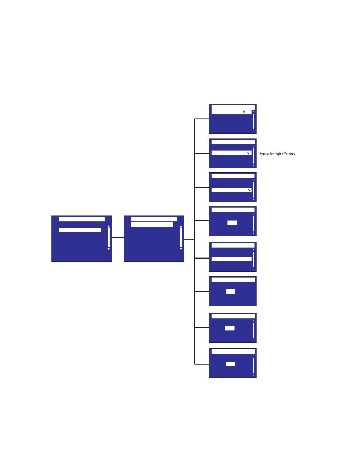
78 4–20kVA Users Guide P-164000669 4–20kVA Users Guide P-164000669—Rev 10
IInn//OOuutt SSeettttiinnggss
The In/Out Settings menus allows control of input and output limits.
Figure 64. In/Out Settings Menu
Local Settings
In/Out settings
On/Off settings
Battery settings
Input signals
Comm settings
User password enable
User password settings
Settings
Output voltage
High Efficiency mode
Protected Bypass
Overload prealarm
Redundancy
Byp freq limit
Byp volt min limit
Byp volt max limit
In/out settings
Output voltage
110 V
√
120 V
127 V
High Efficiency mode
Disabled
√
Enabled
Protected Bypass
Enabled
√
Disabled
Overload prealarm
100
Byp freq limit
Byp volt min limit
Byp volt max limit
Redundancy
Level 0
%
Level 3
Level 4
4
Hz
12
%
12
%
[110V] [120V][127V]
Default:[120V][127V]
[Enabled] [Disabled]
Power the output from
Default: Disabled
[Enabled] [Disabled]
Default: Enabled
[10%] … [102%]
Load % when overload
alarm occurs
Default: 100%
Set redunancy level
Default: 0
Default disables
transfer to Bypass if the
measured bypass
frequency is below
the nominal 4%
Default disables
transfer to Bypass if the
measured bypass voltage
level is below the nominal
output voltage minus 12%
Default disables
transfer to Bypass if the
measured bypass voltage
level is above the nominal
output voltage plus 12%
Level 1
Level 2
Display Menu Screens
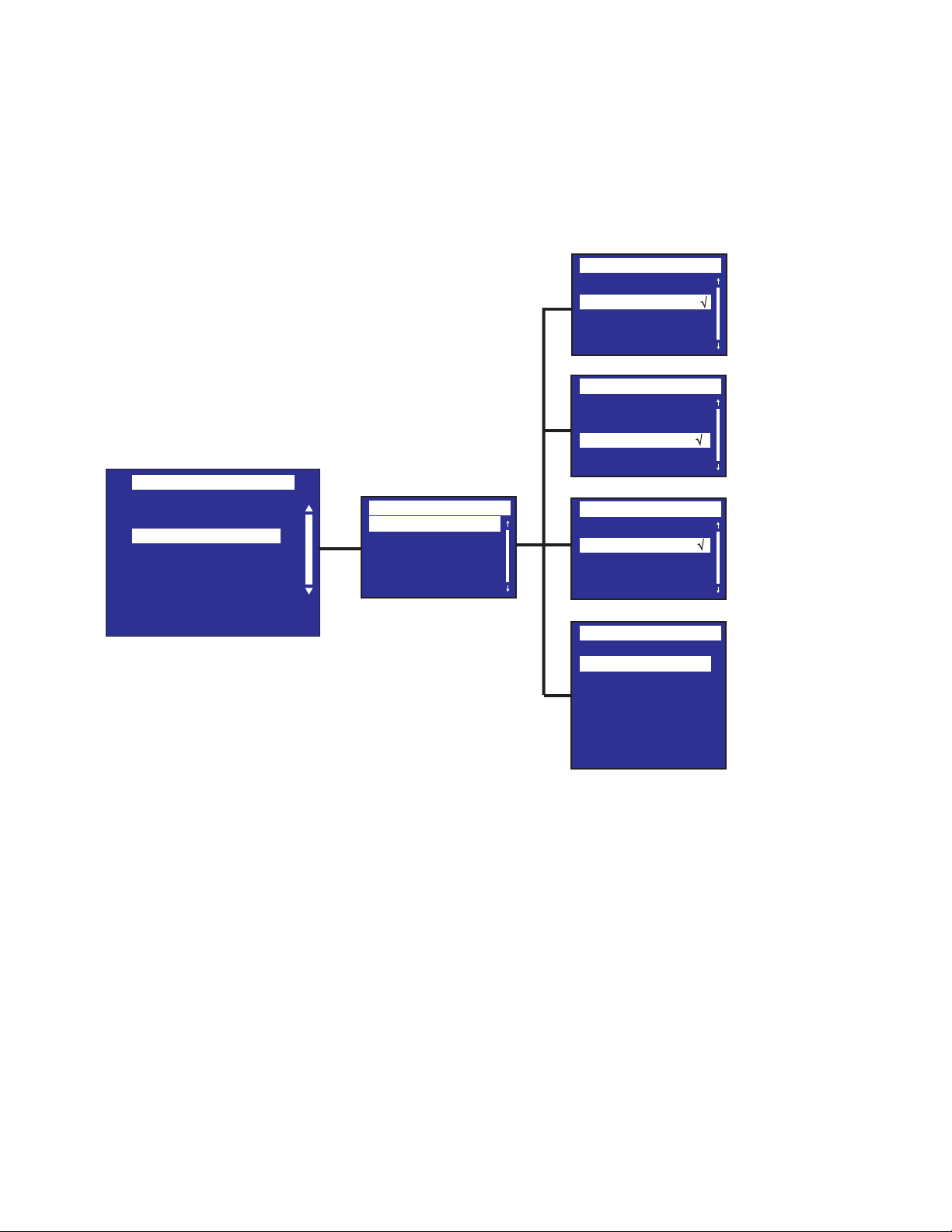
4–20kVA Users Guide P-164000669 4–20kVA Users Guide P-164000669—Rev 10 79
OOnn//OOffff SSeettttiinnggss
The On/Off Settings Menu enables/disables selected automatic restart and shutdown functions.
Figure 65. On/Off Settings Menu
Forced reboot
Disabled
√
Enabled
Local Settings
In/Out settings
On/Off settings
Battery settings
Input signals
Comm settings
User password enable
User password settings
Settings
On/Off settings
Forced Reboot
Auto Restart
Site wiring fault
Energy saving
Energy saving
Disabled √
200 W
400 W
600 W
1000 W
1500 W
2000 W
Select On/O Settings
Auto restart
Enabled
√
Disabled
Site Wiring Fault
Disabled
√
Enabled
(Shut off level)
[Enabled] [Disabled]
[Timer] [10s] … [180s]
When mains recover during
a shutdown sequence:
If set to Enabled, shutdown
sequence will complete and
wait 10 seconds prior to restart,
If set to Disabled, shutdown
sequence will not complete,
UPS stays on.
Default Value: [Enabled]
[Enabled] [Disabled]
[Enabled] [Disabled]
Prevents from starting
the UPS in case of phase
vs neutral wires swapping.
Default: Disabled
[Timer] [1min] … [15min]
[Level] [200W] … [2000W]
If Enabled, UPS will shut-down
back-up time, if load is less
than set value
Default: Disabled [200W]
[Shut o level] [Disabled]
after dened duration. of
Display Menu Screens
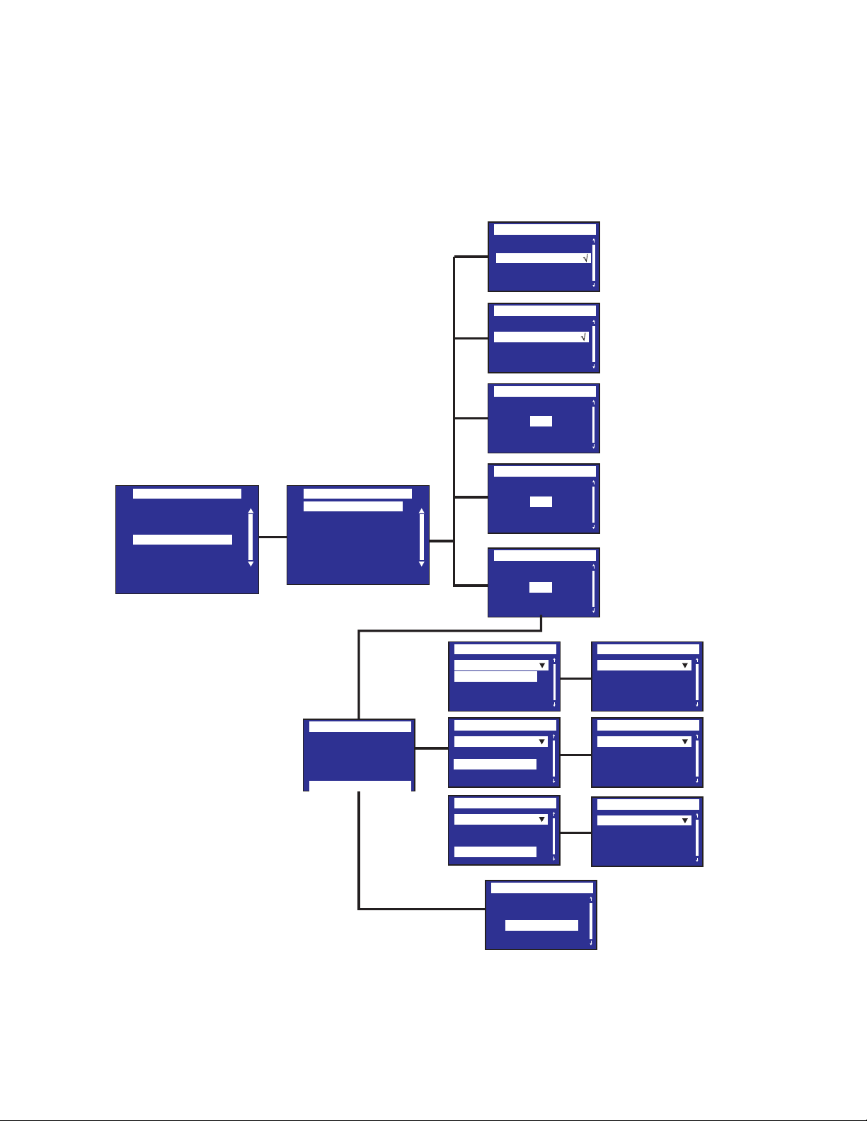
80 4–20kVA Users Guide P-164000669 4–20kVA Users Guide P-164000669—Rev 10
BBaatttteerryy SSeettttiinnggss
The Battery Settings Menu provides control of battery tests, warnings and modes.
Figure 66. Battery Settings Menu
Local Settings
In/Out settings
On/Off settings
Battery settings
Input signals
Comm settings
User password enable
User password settings
Settings
ABM On Off
Auto battery test
Low battery warning
Restart batt. Level
Low BTR warning
External battery
Deep disch.protect.
Battery settings
ABM On Off
Auto battery test
Low battery warning
Enabled
√
Disabled
Restart batt.level
20
Battery settings
Low BTR warning
%
Enabled
√
Disabled
%
00
sec
180
Deep. Disch.Protect.
Yes √
Warranty void if no
No
Auto battery test
Low battery warning
Restart batt. level
Low BTR warning
External battery
Auto Detection
Auto Detection
Manual EBM set.
Manual batt. set.
External battery
Auto Detection
Auto Detection
Manual batt. set.
External battery
Auto Detection
Auto Detection
Manual EBM set.
External battery
Auto Detection
1 BM
External battery
Manual EBM set.
0 Strings
External battery
Manual batt. set.
0 AH
Advanced Battery Mode
[Enabled] [Disabled]
In ABM cycling mode:
[No test] [Every ABM cycle]
In constant charge mode:
[No test] [Every day]
[Every week][Every month]
Default Value: [Every ABM cycle]/[Every
week]
[Capacity] [0%] … [100%]
[Runtime] [0min] … [60min]
The alarm triggers when the
set percentage of battery capacity
or remaining back-up time is reached.
Default Value: [20%] [3min]
[0%]...[100%]
If set, automatic restart will
occur only when percentage
of battery charge is reached.
Default Value: [0%]
Low Battery Warning:
Below 3 min. or less than
setting capacity thershold.
Default Value: [0%]
[Auto detection]
[Manual EBM set.]
[Manual battery set.]
Default Value: [Auto detection]
Using standard EBM, UPS detects
automatically the number
of EBM connected
[Yes] [No]
If set to Yes, the UPS automatically
prevents battery from deep
discharge by adapting end of
back-up time voltage threshold.
Warranty void if set to No.
Default Value: [Yes]
Select Battery Tests
and Warnings
Select Battery Settings
External Battery
Manual EBM set.
Manual batt. set.
Display Menu Screens
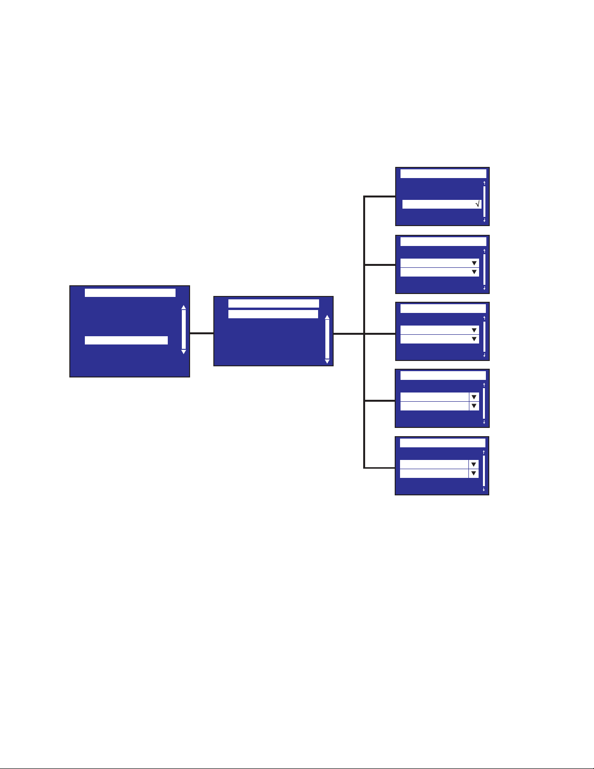
4–20kVA Users Guide P-164000669 4–20kVA Users Guide P-164000669—Rev 10 81
IInnppuutt SSiiggnnaallss
The Input Signals Menu enables/disables power features for the UPS.
Figure 67. Input Signals Menu
Local Settings
In/Out settings
On/Off settings
Battery settings
Input signals
Comm settings
User password enable
User password settings
Settings
Emergency power off
Remote On/Off
On Generator
Force Bypass
Maintain Bypass
Input Signals
Emergency Power Off
Enabled
√
Disabled
Remote On/Off
Disabled
Normally Open
On Generator
Disabled
Normally Open
Force Bypass
Disabled
Normally Open
Maintain Bypass
Disabled
Normally Open
Select Input Signals
[Enabled] [Disabled]
[Normally open]
[Enabled] [Disabled]
[Normally open]
[Enabled] [Disabled]
[Normally open]
[Enabled] [Disabled]
[Normally open]
[Enabled] [Disabled]
Display Menu Screens
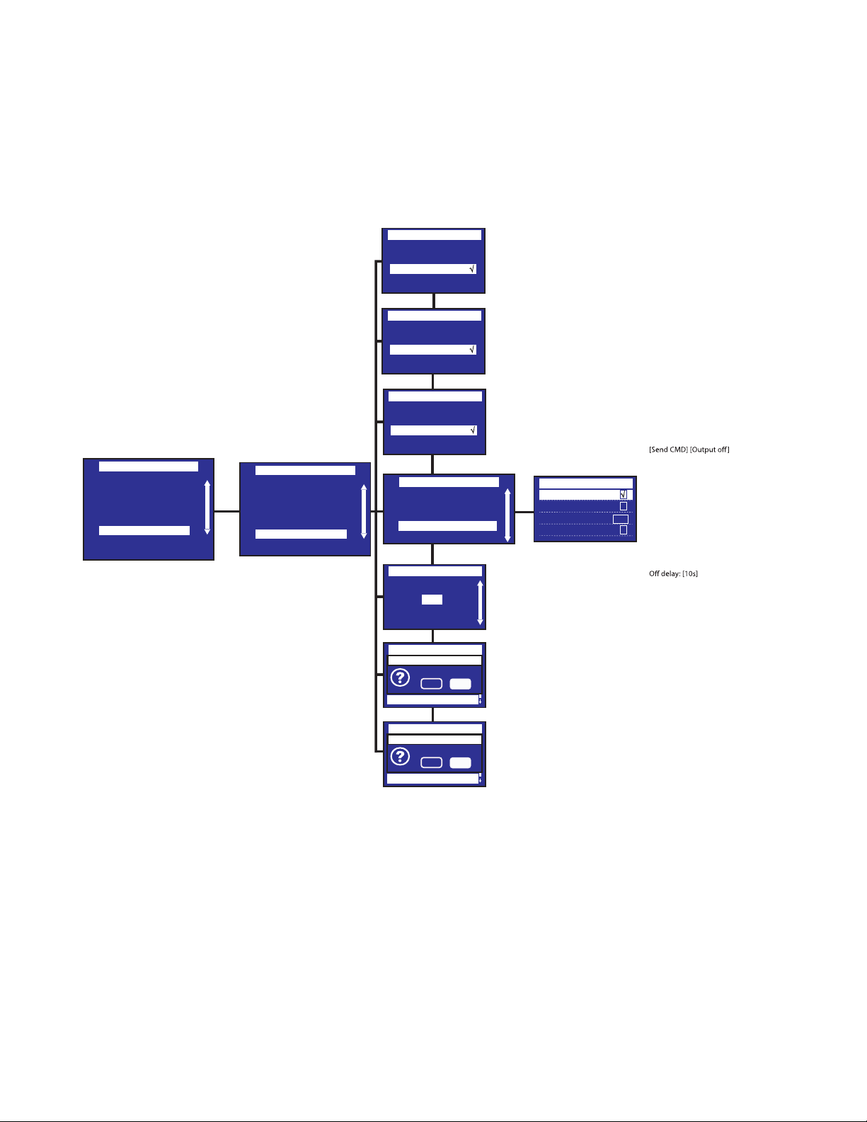
82 4–20kVA Users Guide P-164000669 4–20kVA Users Guide P-164000669—Rev 10
CCoommmm SSeettttiinnggss
The Comm Settings Menu enables/disables some selected control signal features.
Figure 68. Comm Settings Menu
Local Settings
In/Out settings
On/Off settings
Battery settings
Input signals
Comm settings
User password enable
User password settings
Settings
Minislot 1 remote off
Enabled
√
Disabled
Enabled
√
Disabled
Remote command
Enabled
√
Disabled
Battery notice delay
s
0
Comm Settings
Go to bypass
Start battery test
Reset fault state
Restore factory set
Minislot 1 reset
No
Ye s
Are you sure?
Go to bypass
Start battery test
Reset fault state
Restore factory set
No
Ye s
Are you sure?
Minislot 2 reset
Minislot 1 remote off
Remote Command
Shutdown command
Battery notice delay
Comm Settings
Com Settings
Send command
√
Output off √
Off delay 10s
Output off √
Minislot 2 remote off
Minislot 2 remote off
Comm Settings
Minislot 2 reset
Minislot 1 reset
Minislot 2 remote off
Remote command
Shutdown command
Battery notice delay
Minislot 1 reset
Minislot 2 reset
Battery settings
Minislot 1 remote off
[Yes] [No]
[Yes] [No]
[0s] ... [99s]
Sets delay before displaying
on battery information
to software..
Default Value: [0s]
Default Value: [Enabled]
Default Value: [Enabled]
[Enabled] [Disabled]
If Enabled, shutdown or restart
commands from software are
authorized.
Default Value: [Enabled]
[OFF delay][Restart]. Sets events
or fault that will actuate Output
signal parameters through
external contact connector or
RS232 port
[Send CMD]: Select [ ] [Unselect]
[Output OFF]: Select [ ] [Unselect]
[OFF delay]: [0s] …[999s]
[Restart]: [Yes] [No] authorized.
Default Values:
Send CMD: [Unselect]
Output OFF: Select [ ]
Restart: Select [ ]
√
√
√
√
Display Menu Screens
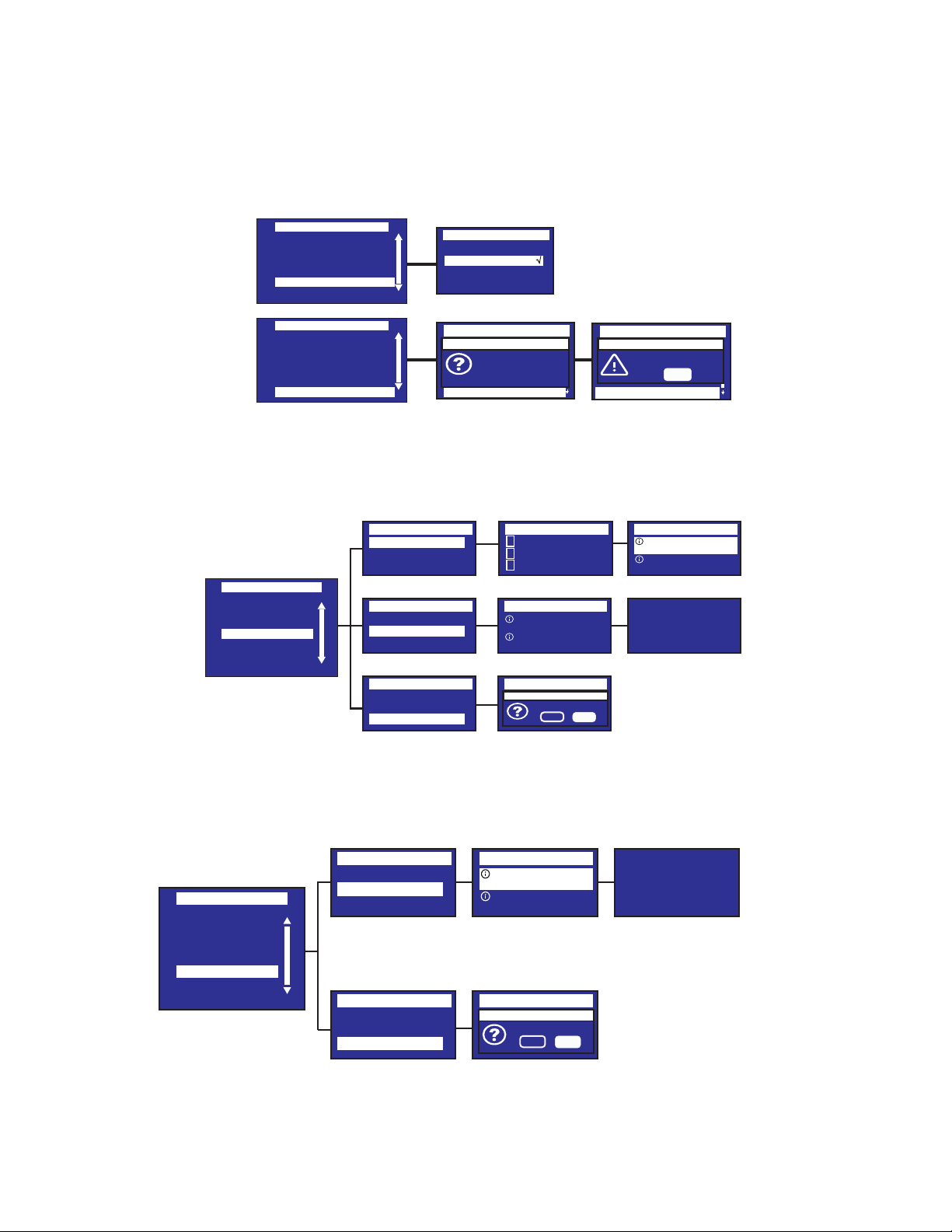
4–20kVA Users Guide P-164000669 4–20kVA Users Guide P-164000669—Rev 10 83
UUsseerr PPaasssswwoorrdd SSeettttiinnggss
Figure 69. Password Menus
On/Off settings
Battery settings
Input signals
Comm settings
User password enable
User password settings
Settings
User Password Enable
Disabled
√
Enabled
On/Off settings
Battery settings
Input signals
Comm settings
User password enable
User password settings
Settings
Settings
Go to bypass
Start battery test
Reset fault state
Restore factory set
Please set
password
0000
Settings
Go to bypass
Start battery test
Reset fault state
Restore factory set
Protected access
OK
Successful !
Protected access
User password settings
User password settings
EEvveenntt LLoogg
Figure 70. Event Log
Control
Measurements
Settings
Event Log
Fault Log
Identification
Register Product
Menu
Event Log
Event filter
Event list
Reset event list
Event Log
Event filter
Event list
Reset event list
Event Log
Event filter
Event list
Reset event list
09/26/2017 09:28:27
Event Log
√ Display faults
√ Display alarms
√ Display events
Event Log
09/26/20
09:28 ABM Off
09/26/20
09:28 Line Converter
Event Log
09/26/20
09:28 ABM Off
09/26/20
09:28 Line Converter
Reset event list
No
Ye s
Are you sure?
Event Log
09/26/20
09:28 Line Converter
09/26/20
09:28 ABM Off
Event: UPM2
Code: 0x009 1/37
FFaauulltt LLoogg
Figure 71. Fault Log Menu
Control
Measurements
Settings
Event Log
Fault Log
Identification
Register Product
Menu
Fault Log
Fault list
Reset fault list
Fault Log
Fault list
Reset fault list
Fault Log
09/26/20
09:28 ABM Off
09/26/20
09:28 Line Converter
Reset fault list
No
Ye s
Are you sure?
09/26/2017 09:28:27
Fault Log
09/26/20
09:28 Min inverter
09/26/20
Battery need service
Fault: UPM2
Code: 0x607 1/3
Display Menu Screens
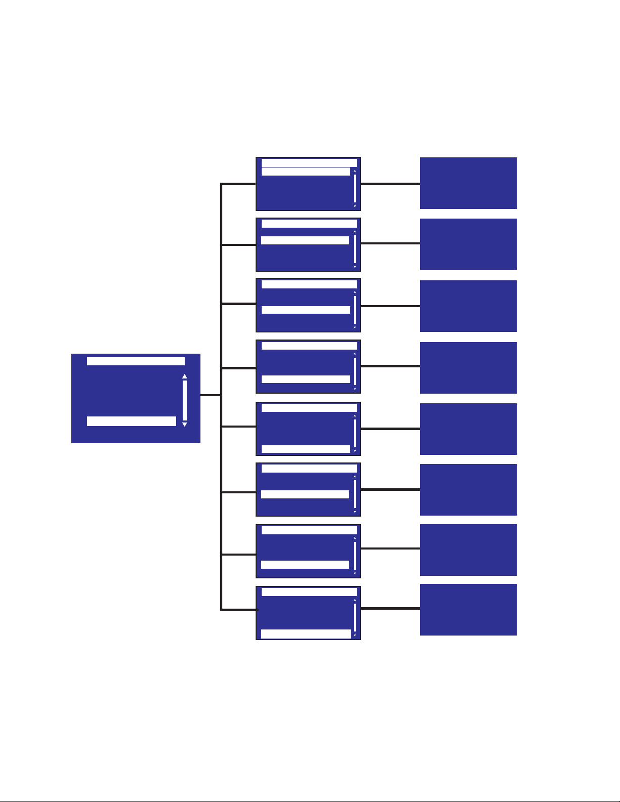
84 4–20kVA Users Guide P-164000669 4–20kVA Users Guide P-164000669—Rev 10
IIddeennttiiffiiccaattiioonn
The Identification screen shows the product type and installed accessories.
Figure 72. Identification Menu
Measurements
Control
Settings
Event log
Fault log
Identification
Register product
Menu
Identification
Product type/model
Part/Serial number
UPS/NMC firmware
CSB/EBM firmware
Com card IPv4
Type
Eaton_9PXM
4KVA
Part number
9PXM_4kVA
0000000000
Serial number
00.00.0098
NA
UPS CSB Firmware
00.91.0048
00.00.0000
UPS EBM Firmware
UPS firmware
COM card IPv4
NA
Detected accessories
Supercharger:
Maintenance bypass:
No
Identification
Product type/model
Part/Serial number
UPS/NMC firmware
CSB/EBM firmware
Com card IPv4
Identification
Product type/model
Part/Serial number
UPS/NMC firmware
CSB/EBM firmware
Com card IPv4
Identification
Product type/model
Part/Serial number
UPS/NMC firmware
CSB/EBM firmware
Com card IPv4
Identification
Product type/model
Part/Serial number
UPS/NMC firmware
CSB/EBM firmware
Com card IPv4
Identification
Com card MAC
Detected accessories
CSB/EBM firmware
Com card IPv4
Com card IPv6
Identification
Com card MAC
Detected accessories
CSB/EBM firmware
Com card IPv4
Com card IPv6
Identification
Com card MAC
Detected accessories
CSB/EBM firmware
Com card IPv4
Com card IPv6
Model
NMC firmware
COM card IPv6
NA
00:00:00:00:00:00
COM card MAC
No
Display Menu Screens

4–20kVA Users Guide P-164000669 4–20kVA Users Guide P-164000669—Rev 10 85
RReeggiissttrraattiioonn SSeeccttiioonn
The Register product screen provides directions to register the product with Eaton.
Figure 73. Register Product Menu
Date / Time
International
Format :
23/05/2020 15 :05
Date / Time
MM/DD/YYYY US
Format :
02/05/2020 03 :05
Date / Time
International
Format :
23/05/2020 15 :05
Date / Time
MM/DD/YYYY US
Format :
02/05/2020 03 :05
Settings
Event Log
Fault Log
Identification
Register Product
Menu
Please register at:
www.eaton.com
Type
Eaton...9PXM
Display Menu Screens

86 4–20kVA Users Guide P-164000669 4–20kVA Users Guide P-164000669—Rev 10
Display Menu Screens

4–20kVA Users Guide P-164000669 4–20kVA Users Guide P-164000669—Rev 10 87
CChhaapptteerr 88 CCoommmmuunniiccaattiioonn
88..11 IInntteelllliiggeenntt PPoowweerr MMaannaaggeerr
Eaton offers several methods of communicating with your Eaton 9PXM system in addition to the front panel
display:
• Intelligent Power Manager® (IPM) Power Management Software
• Optional Interface Kits
• Communication ports
• Dedicated Input Signals
• DB-9 Communication Port
• Communication slots
IInntteelllliiggeenntt PPoowweerr MMaannaaggeerr
Eaton’s Intelligent Power Manager (IPM) software provides the tools needed to monitor and manage power
devices in a physical or virtual environment. This innovative software solution ensures system uptime and data
integrity by allowing the user to remotely monitor, manage and control UPSs and other devices on their
network. IPM provides a solution that is easy to use and maintains business continuity.
88..22 OOppttiioonnaall IInntteerrffaaccee KKiittss
For computer systems that already have UPS monitoring software, Eaton offers interface cable kits for
connecting the Eaton 9PXM system to your computer system. The kit includes the cable, adapters, and
instructions.
88..33 CCoommmmuunniiccaattiioonn PPoorrttss
CCoommmmuunniiccaattiioonn PPoorrttss
UPS Communications Ports
External communication ports are located on the top rear panel of the UPS (see Figure 74 ). They are identified
as follows:
• CN6 - ROO and On-Generator signals
• CN5 - Building input signals (for future option)
• Maintenance bypass signals
• EPO
• External slot select signals and External CAN signals, goes to EBM CSB
• DB-9 (RS-232) port
• USB port
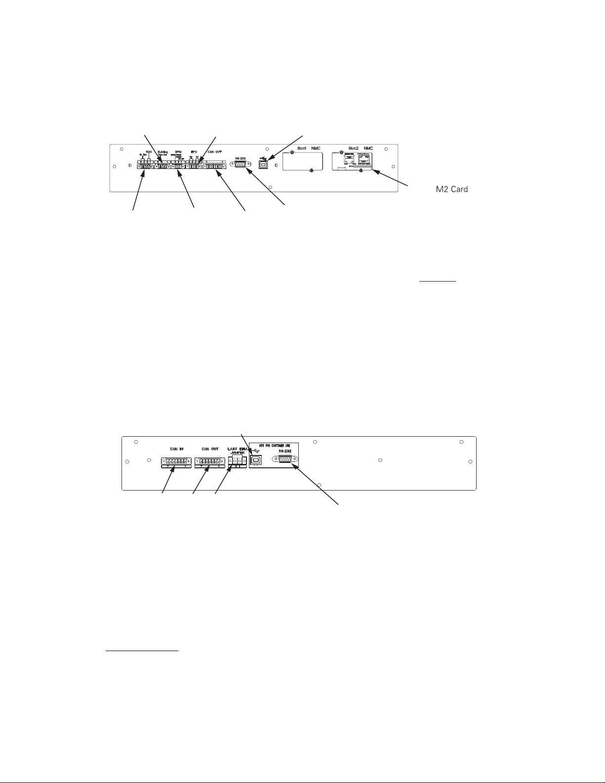
88 4–20kVA Users Guide P-164000669 4–20kVA Users Guide P-164000669—Rev 10
Figure 74. UPS Communications Ports
CN17 - DB-9 Communication Port
CN12 - USB Communication
Port
CN4
CN7
CN5
Network
(Optional)
CN13CN6
ACT
100M
MAC:
ETHERNET
Settings/Sensor
RS232UPS Data
EBM Communication Ports
External communication ports are located on the top rear panel of the EBM (see Figure 75 ). They are identified
as follows:
• External slot select signals and external CAN signals from UPS
• External slot select external CAN signals to next EBM
• Last EBM Jumper
• DB-9 (RS-232) port
• USB port
Figure 75. EBM Communication Port
CN5 - DB-9 Communication Port
CN12 - USB Communications Port
CN3
CN4
CN6
Refer to detail A in for the type of signal connectors used.
88..44 DDeeddiiccaatteedd IInnppuutt SSiiggnnaallss
DDeeddiiccaatteedd IInnppuutt SSiiggnnaallss
Emergency Power-off (EPO):Connection to a facility Emergency Shutdown switch provides a method for
emergency Eaton 9PXM system shutdown.
EPO Connections
In the 9PXM UPS, EPO can be configured either as Normally Open (NO) or Normally Closed (NC) contacts.
Connector CN7 on the rear panel of the UPS is used for EPO.
Dedicated Input Signals
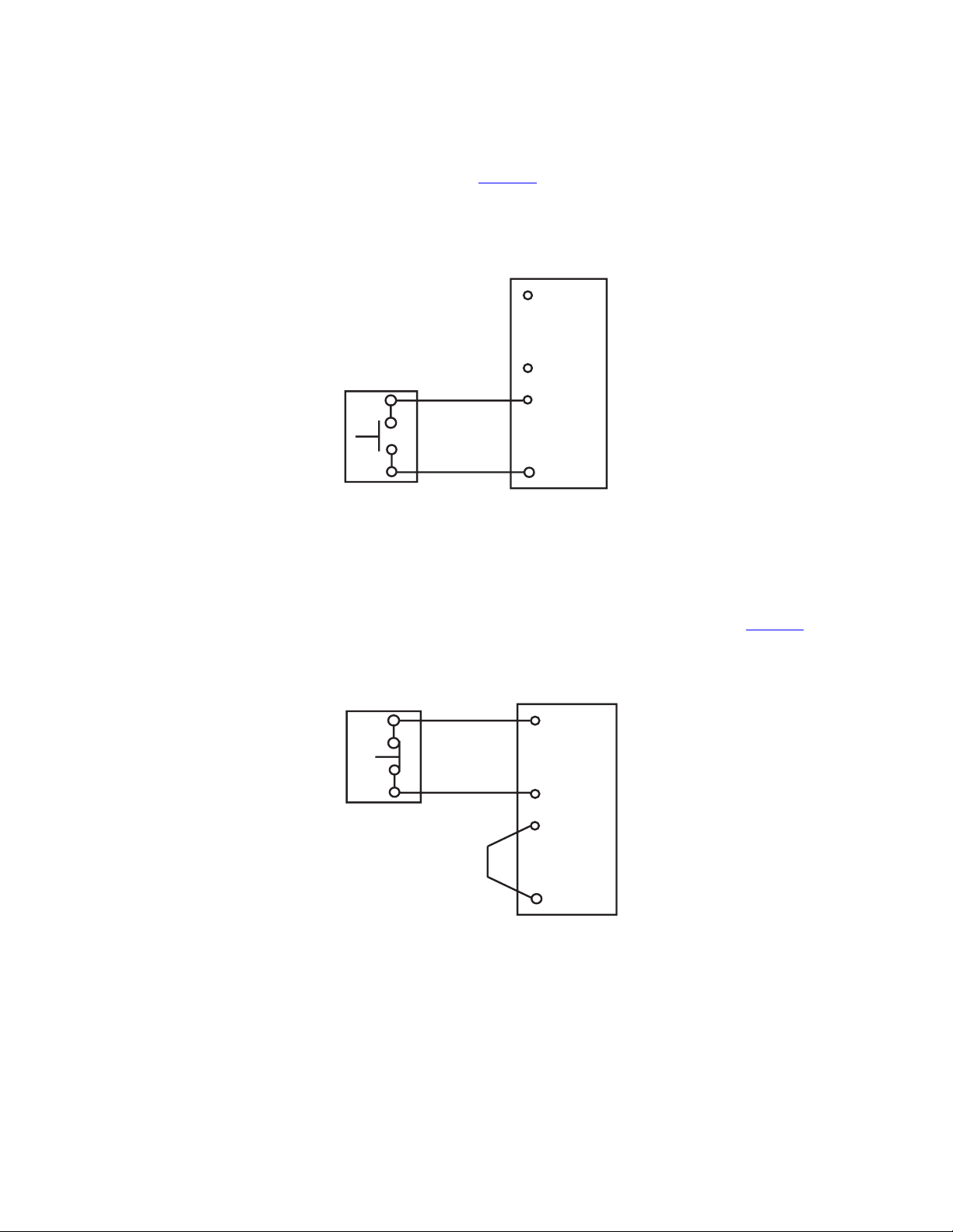
4–20kVA Users Guide P-164000669 4–20kVA Users Guide P-164000669—Rev 10 89
NO Configuration
For Normally Open operation, configure as in Figure 76 with external switch wired to Pins 3 and 4 of CN7.
18AWG Twisted wire is to be used for EPO connections.
Figure 76. Normally Open Connections
REPO
Switch
(NO)
Twisted
Wires
3
3
REPO TB
NOTE REPO switch rating is 24 Vdc. 1A minimum
NOTE The REPO switch must be a latching type switch not tied to any other cicuits.
4
4
2
1
NC Configuration
For Normally Closed operation, add a jumper between Pins 3 and 4 of CN7 and the EPO switch should be
connected to Pins 1 and 2 and should be closed during normal operation of the UPS (see Figure 77 ).
Figure 77. EPO Normally Closed Connections
REPO
Switch
(NO)
Twisted
Wires
1
3
REPO TB
2
4
2
1
NOTE REPO switch rating is 24 Vdc. 1A minimum
NOTE The REPO switch must be a latching type switch not tied to any other cicuits.
Maintenance Bypass: The signal from an external bypass switch, to isolate the Eaton 9PXM system for
maintenance purposes, tells the UPS to go into Internal Bypass mode.
On Generator: The signal allows the UPS to optimize its operation with the generator by transferring the UPS
from High Efficiency mode to Normal (double conversion) mode as long as High Efficiency is set as the default
mode of UPS operation. See IN/Out setting.
Dedicated Input Signals

90 4–20kVA Users Guide P-164000669 4–20kVA Users Guide P-164000669—Rev 10
88..55 DDBB--99 CCoommmmuunniiccaattiioonn PPoorrtt
Table 7 explains the functions of the pins on the Eaton 9PXM DB-9 communication port. This port is on the
Eaton 9PXM UPS rear panel, as shown in Figure 75 .
Pin Function Description
1
Low Battery Alarm
Pin 1 shifts from RS-232 Low (negative voltage) to RS-232 High (positive
voltage) and remains high whenever the UPS enters a Low Battery alarm
state.
2
RS-232 Transmit Data
Sends outgoing RS-232 communication data at 9600 baud, 8 bits, no
parity, 1 stop bit.
3
RS-232 Receive Data/
RS-232 Shutdown
RS-232 Receive Data Function. Receives incoming RS-232 communication
data at 9600 baud,8 bits, no parity, 1 stop bit.
RS-232 Shutdown Function. If Pin 3 receives an RS-232 Low signal (+Vdc)
for at least 5 seconds, but not more than 7 seconds, during an AC Failure
condition, the UPS output shuts off following a delay of 120 seconds (±5
seconds).
4
Reserved Loopback to Pin 6
5
Common Signal Ground
6 Reserved Loopback to Pin 4
7
No Connection Open Pin
8
AC Fail Signal
(On-Battery)
Pin 8 shifts from RS-232 Low (positive voltage) to RS-232 High (positive
voltage) and remains high for 15 seconds (±1 second) after the UPS
detects an AC Failure condition, assuming the condition still exists after
the 15 seconds.
When the AC Failure condition no longer exists, the signal returns to the
RS-232 Low state (positive voltage).
9
No Connection/
DC Supply Voltage
The UPS is factory-set with Pin 9 disconnected, but can be enabled
through a technician-replaceable jumper inside the UPS. The jumper
setting MUST be changed by a qualified service technician.
When enabled, Pin 9 provides supply voltage for use with external
connectivity devices requiring DC power directly from the UPS DB-9 port
(nominal 12 Vdc/5W; 8V minimum, 24V maximum). Use only Eaton brand
connectivity devices.
88..66 CCoommmmuunniiccaattiioonn SSlloottss
The Eaton 9PXM UPS has two communication slots that allow quick installation of the optional communication
cards. These interface cards extend the capabilities of the Eaton 9PXM system to provide compatibility with
network and remote monitoring/management systems.
Type of connectivity cards that can be installed include:
Network Card M-2
The Eaton Network Card-M2 allows an Eaton UPS to directly connect to the Ethernet network and the Internet,
supporting real-time monitoring and control of UPSs across the network via a standard Web browser, SNMP-
compliant network management system or power management software. Environmental monitoring is also
possible via an Environmental Monitor Probe (EMP)
DB-9 Communication Port

4–20kVA Users Guide P-164000669 4–20kVA Users Guide P-164000669—Rev 10 91
Network and Modbus Card MS
The Eaton Network and MODBUS Card-MS provides continuous, reliable and accurate remote monitoring of a
UPS system through a Building Management System (BMS) or Industrial Automation System (IAS). Enabling
data to be integrated from the UPS into a wide variety of management systems, the MODBUS Card-MS
combines an SNMP agent, HTTP/Web server and a MODBUS card, facilitating UPS supervision from any
network monitoring system using SNMP and traps, or any web browser.
Relay Card—MS
The Eaton Relay Card-MS enables automatic shutdown and network monitoring of UPS system status through
a connected computer with a dedicated adapter that provides the essential dry-contact interface between an
Eaton UPS and any relay-connected computer as well as a variety of industrial applications. The Relay Card-MS
is compatible with all Eaton UPSs that have a Minislot.
Communication Slots

92 4–20kVA Users Guide P-164000669 4–20kVA Users Guide P-164000669—Rev 10
Communication Slots

4–20kVA Users Guide P-164000669 4–20kVA Users Guide P-164000669—Rev 10 93
CChhaapptteerr 99 MMaaiinntteennaannccee
99..11 RRoouuttiinnee MMaaiinntteennaannccee
This chapter provides maintenance information to help maintain proper UPS operation.
NOTE 1 Observe important safety precautions while performing these checks.
NOTE 2 Eaton recommends that you schedule preventive maintenance checks at least every six
months.
The Eaton 9PXM system is designed to provide years of trouble-free operation. Its internal control system
checks the batteries and inverter periodically to ensure reliable operation.
The Eaton 9PXM UPS and optional external battery cabinets do require some attention to assure continued
reliable service. Follow Eaton's recommended maintenance schedule, which includes:
• Check operating environment for clean, cool, dry conditions.
• Inspect and clean the area around the UPS
• Check operation of fans (power modules).
• Check the batteries.
For more information on preventive maintenance checks, contact your service representative.
99..22 SSttoorraaggee TTeemmppeerraattuurree
Store the Eaton 9PXM battery modules (in the UPS or external battery cabinet) at –20 to +40°C (–4 to +104°F).
Batteries will have a longer shelf life if they are kept below +25°C (+77°F). The Eaton 9PXM UPS or battery
cabinet without batteries may be stored at –40 to +60°C (–40 to +140°F).
99..33 EExxtteerrnnaall BByyppaassss SSwwiittcchh ((MMaakkee BBeeffoorree BBrreeaakk OOnnllyy)) OOppeerraattiioonn
Press the red button beside the switch before turning the Eaton MBB bypass switch. This button:
• Sends an electrical signal to the UPS to switch to the internal Bypass mode (if it is not already operating in
that mode ).
• Operates a mechanical interlock, to prevent the switch from being turned without first signaling the UPS.
Failure to understand the correct bypass sequence and position may cause the critical load to be dropped.
Damage to the power modules or the Bypass switch can occur.
• If the UPS remains in Bypass Mode and incoming AC power is lost, the load is automatically dropped. The
UPS must be in Normal Mode to provide battery backup power.
• In the UPS or LINE position, AC input power is still connected to the input terminals inside the UPS.
• If the UPS is in the standby mode and the bypass switch is in the LINE or UPS positions pressing
the red bypass switch interlock button will energize the UPS output.
• Do not attempt to push the red interlock button or attempt to move the bypass switch handle if the
UPS is operating on battery power.
• If you have any questions or problems with the bypass operation, call the Help Desk (see , “
11.2 Service and Support ” ).
See “ 3.6 Bypass Overview ” for additional information.
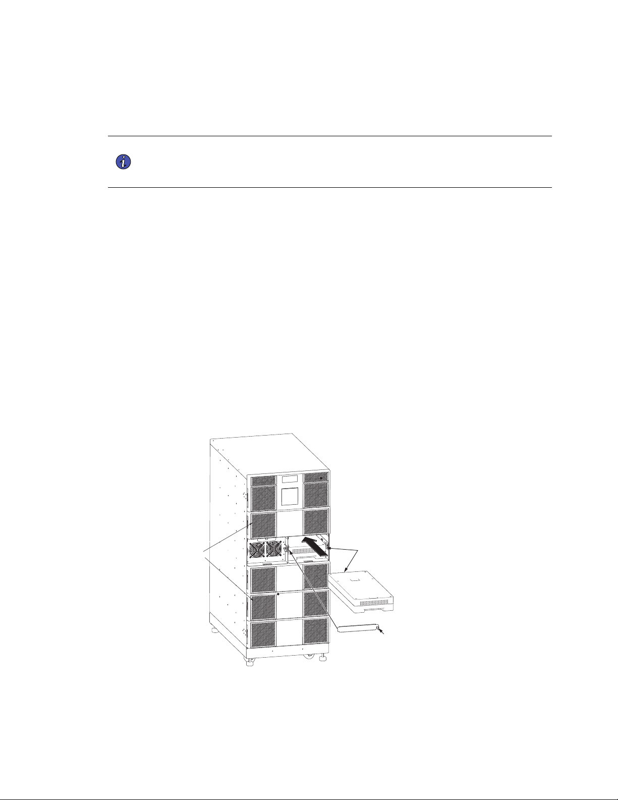
94 4–20kVA Users Guide P-164000669 4–20kVA Users Guide P-164000669—Rev 10
99..44 BBaatttteerryy RReeppllaacceemmeenntt
The Eaton 9PXM hot-swappable feature lets you replace the battery modules without disconnecting the load or
damaging the batteries.
NOTE The Eaton 9PXM UPS will operate with uncharged (or no) batteries, but will have limited
(or no) battery backup capability. The UPS will indicate an alarm with a insufficient
number of batteries present. One battery string (two battery modules) must be installed
adjacent to each power module.
To replace a two-battery slot in pairs:
1. Remove the front cover.
The cover has magnetic latches on the left and right sides that hold it in place.
2. Loosen the captive screw on the retaining bracket and slowly pull the upper battery module out of the
cabinet.
3. Repeat the procedure with the lower battery module.
4. Treat the original and replacement battery modules with care to avoid damaging connectors or internal
circuitry. Label the original batteries with masking tape or some other identifier. Record the serial number
of the replacement modules for your warranty.
5. Insert the replacement battery modules by sliding the lower module carefully into the cabinet. Repeat for
the upper replacement module.
6. Reinstall the retaining bracket and tighten the captive screw.
7. Replace the front cover.
Figure 78. Battery Replacement
Retaining Bracket
Battery
Modules
Captive
Screw
Front Covers
Battery Replacement
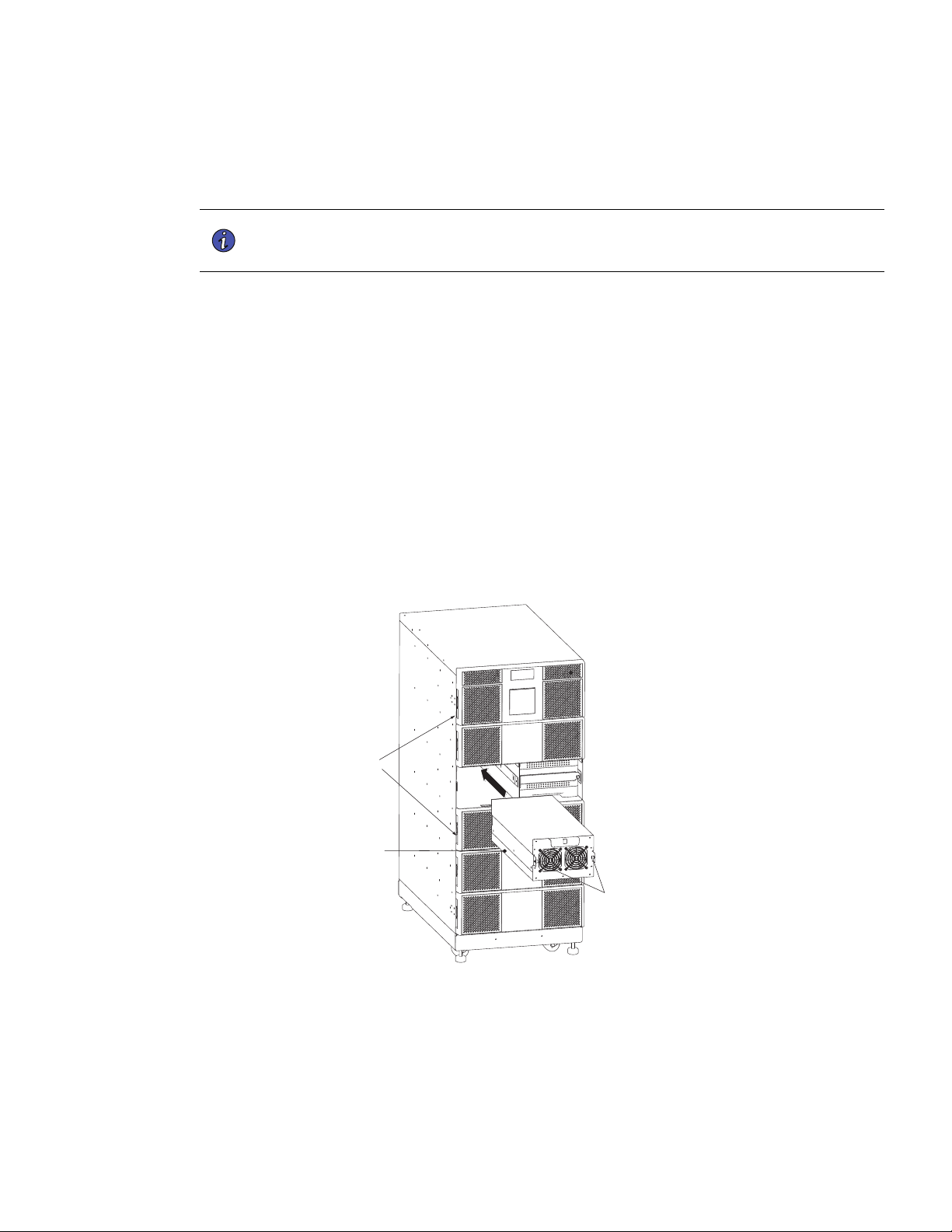
4–20kVA Users Guide P-164000669 4–20kVA Users Guide P-164000669—Rev 10 95
99..55 PPoowweerr MMoodduullee RReeppllaacceemmeenntt
The Eaton 9PXM easy replace feature lets you replace a power module without disconnecting the load or
damaging the UPS.
NOTE The UPS may switch to internal Bypass mode if the remaining power modules are
insufficient to supply the required power. If empty slots exist, install replacement
modules before removing original ones.
Use care in removing and installing power modules. To remove a power module:
1. Remove the front cover.
The cover has magnetic latches on the left and right sides that hold it in place.
2. Loosen the captive screws at the sides of the power module and slowly pull the power module out of the
cabinet.
3. Treat the original and replacement power modules with care to avoid damaging connectors or internal
circuitry. Label the original power modules with masking tape or some other identifier. Record the serial
number of the replacement power modules for your warranty.
4. Insert the replacement power module by sliding it carefully into the cabinet.
5. Tighten the captive screws to the UPS cabinet.
6. Replace the front cover.
Figure 79. Power Module Replacement
Captive Screws
Power Module
Front Covers
Power Module Replacement

96 4–20kVA Users Guide P-164000669 4–20kVA Users Guide P-164000669—Rev 10
99..66 UUPPSS FFiirrmmwwaarree UUppggrraaddee
!
IMPORTANT
To ensure you have the most up-to-date content and information for this product, please review the latest
manual revision on our website, https://www.eaton.com/9PXM
FW upgrade program and instructions are located at the following web link: https://www.eaton.com/9PXM.
UPS Firmware Upgrade

4–20kVA Users Guide P-164000669 4–20kVA Users Guide P-164000669—Rev 10 97
CChhaapptteerr 1100 SSppeecciiffiiccaattiioonnss
1100..11 NNoommiinnaall EElleeccttrriiccaall IInnppuutt aanndd OOuuttppuutt
This section provides the following specifications for the Eaton 9PXM models:
• Nominal Electrical Input and Output
• Combined UPM Power Ratings
• Circuit Breakers
• Environmental and Safety
• Battery
• Output Run Times
• Weights and Dimensions
Table 7. Electrical Input and Output
Nominal Input Voltage 110/220, 120/208, 120/240, 127/220 Vac
Input Voltage Range
80V–144V (Line neutral)
Nominal Output Voltage 110/220, 120/208, 120/240, 127/220 Vac
Nominal Frequency Online: 60 Hz auto-sensing; output frequency tracks input
frequency to selectable limit (±0.1 to ±5.0 Hz; ±3.0 Hz default);
switches to battery operation outside this tolerance On battery:
60 Hz ±0.1 Hz
Regulation
±5% load regulation (under any line, load, or battery condition)
Voltage Waveform Sine wave; <5% THD at rated linear loads, computer-grade
power
Overload Capability 115% for 3 seconds; >115% for 12 cycles
DC Input Protection DC fuse
Output Protection Microprocessor-sensed overvoltage and overcurrent, with fuse
backup
Efficiency in Double-Conversion mode >93%
1100..22 CCoommbbiinneedd UUPPMM PPoowweerr RRaattiinnggss
Table 8. Power Ratings
Combined UPS
Ratings
Split Phase
Voltage L-N/L-L
Max Input
Current/Phase
Output Current L-
N*
Input Service Heat Dissipation
— Normal Mode
4KVA, 3600 Watts
(1UPM)
120/208V or 240V
20
16.67A/phase 25A 850 BTU/hr
8KVA, 7200 Watts
(2 UPMs)
120/208V or 240V
40
33.34A/phase 50A 1700 BTU/hr
12KVA, 10800
Watts (3 UPMs)
120/208V or 240V 60 50.01A/phase 75A 2500 BTU/hr

98 4–20kVA Users Guide P-164000669 4–20kVA Users Guide P-164000669—Rev 10
Table 8. Power Ratings (Continued)
Combined UPS
Ratings
Split Phase
Voltage L-N/L-L
Max Input
Current/Phase
Output Current L-
N*
Input Service Heat Dissipation
— Normal Mode
16KVA, 14400
Watts (4 UPMs)
120/208V or 240V 80 66.68A/phase 100A 3400 BTU/hr
20KVA, 18000
Watts (5 UPMs)
120/208V or 240V
100
83.35A/phase 125A 4250 BTU/hr
*Note: Relative to output load factor, for 120V L to N current
1100..33 CCiirrccuuiitt BBrreeaakkeerrss
CCiirrccuuiitt BBrreeaakkeerrss
Table 9. Circuit Breaker Sizes
Required Input Circuit Breaker Sizes
UPS Capacity Input Circuit Breaker
4kVA 25A
8kVA 50A
12kVA 75A
16kVA 100A
20kVA 125A
1100..44 EEnnvviirroonnmmeennttaall aanndd SSaaffeettyy
Table 10. Environmental and Safety
Operating Temperature
0°C to 40°C (32°F to 104°F)
Optimal battery performance: 25°C (77°F)
Storage Temperature
UPS with battery modules: –20°C to +40°C (–4°F to 104°F)
UPS without batteries: –40°C to +60°C (–40°F to 140°F)
Relative Humidity
5–95% noncondensing
Operating Altitude
Up to 3,050 meters above sea level (10,000 ft)
The maximum operating ambient temperature decreases 1°C
per 300m above 1525m (2°F per 1000 ft above 5000 ft)
Non-Operating Altitude
Up to 12,200m above sea level (40,000 ft)
Ventilation
The air around the UPS must be clean and free of dust,
corrosive chemicals, and other contaminants. The Eaton 9PXM
UPS uses internal fans to circulate the air for cooling. The air
must be free to circulate around the UPS and battery cabinet(s).
Do not operate the UPS in a sealed room or container.
Audible Noise
Less than 67 dBA
Circuit Breakers

4–20kVA Users Guide P-164000669 4–20kVA Users Guide P-164000669—Rev 10 99
Table 10. Environmental and Safety (Continued)
Surge Suppression
EN 61000-4-5
Safety Conformance
CSA C22.2, No. 107.3; UL1778 5th Edition
Agency Markings
NOM, UL, CUL, FCC
EMC (Class A)
EN 62040-2, FCC Part 15, EN 61000-4-2 level 3 Criteria B, EN
61000-4-3 level 3 Criteria A, EN
61000-4-4, 61000-4-5, 61000-4-6, 61000-4-8
1100..55 BBaatttteerryy RRaattiinnggss
Table 11. Battery Ratings
Configuration (2) 60V, 9 Ah battery modules per two-battery slot
Voltage 120 Vdc
Type Sealed, maintenance–free, valve–regulated, lead–acid
Charging
ABM recommends 48 hours of charging after a discharge.
Optional super chargers at higher current ratings are available.
1100..66 OOuuttppuutt RRuunn TTiimmeess
Model
Nominal Output
Voltage (VAC) L-N
/L-L
Output VA/W
Rating @ Nominal
Input Connection Output (See Output
Receptacles Figure
74)
Minimum Run time
at full power
load**
Split-Phase
20kVA 12-Slot
110/220
120/208
120/240
18000/16200
20000/18000
20000/18000
20000/18000
Hardwired Hardwired +
Optional
Receptacles
5.8 min
Split-Phase
16kVA 8-Slot
110/220
120/208
120/240
16000/14400 Hardwired Hardwired +
Optional
Receptacles
5.8 min
1100..77 WWeeiigghhttss aanndd DDiimmeennssiioonnss
Table 12. Weights and Dimensions
Cabinet Size
Package
Height
Package
Length
Package
Width
Package
Weight
Product
Height
Product
Length
Product
Width
Product
Weight
With Caster
Tray (lbs)
12 Slot UPS
118.1 cm
(46.5")
88.9 cm
(35")
64.1 cm
(25.25")
110.7 kg
(244 lb)
92.7 cm
(36.5")
87.6 cm
(34.5")
44.5 cm
(17.5")
77.1 kg
(170 lb)
93.4 kg (206
lb)
8 Slot UPS
88.9 cm
(35")
88.9 cm
(35")
64.1 cm
(25.5")
90.3 kg
(199 lb)
63.5 cm
(25")
87.6 cm
(34.5")
44.5 cm
(17.5")
56.7 kg
(125 lb)
73 kg
(161 lb)
12 Slot EBM
118.1 cm
(46.5")
88.9 cm
(35")
64.1 cm
(25.5")
108.5 kg
(239 lb)
92.7 cm
(36.5")
87.6 cm
(34.5")
44.5 cm
(17.5")
74.8 kg
(165 lb)
91.2 kg (201
lb)
Battery Ratings
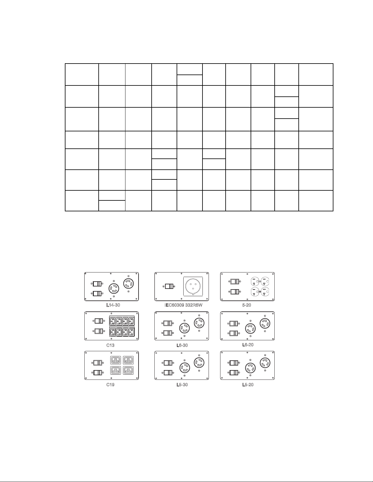
100 4–20kVA Users Guide P-164000669 4–20kVA Users Guide P-164000669—Rev 10
Table 12. Weights and Dimensions (Continued)
8 Slot EBM
88.9 cm
(35")
88.9 cm
(35")
64.1 cm
(25.5")
88 kg
63.5 cm
(25")
87.6 cm
(34.5")
44.5 cm
(17.5")
54.4 kg
(120 lb)
70.8 kg (156
lb)
(194 lb)
Battery
Module
16.5 cm
(6.5")
64.8 cm
(25.5")
30.5 cm
(12")
15.9 kg
(35 lb)
7.6 cm
(3")
54.6 cm
(21.5")
21.6 cm
(8.5")
15 kg
N/A
(33 lb)
Split Phase
Power
module
29.2 cm
(11.5")
68.6 cm
(27.5")
38.1 cm
(15")
15.4 kg
(34 lb)
15.2 cm
(6")
58.4 cm
(23")
21.6 cm
(8.5")
12 kg
N/A
(26.5 lb)
Super
Charger
29.2 cm
(11.5")
68.6 cm
(27.5")
38.1 cm
(15")
12.5 kg
(27.5 lb)
15.2 cm
(6")
58.4 cm
(23")
21.6 cm
(8.5")
10.2 kg
(22.5 lb)
N/A
Rail Kit
26.7 cm
(10.5")
101.6 cm
(40")
61 cm
27.4 kg
(60.5 lb)
14 cm
58.4 cm
(23")
49.5 cm
(19.5")
15.6 kg
(34.5 lb)
N/A
(24") (5.5")
Caster
25.4 cm
(10")
101.6 cm
(40")
61 cm
28.1 kg
(62 lb)
12.7 cm
(5")
73.7 cm
(29")
50.8 cm
(20")
16.3 kg
(36 lb)
N/A
(24")
Floor anchor
kit
20.3
25.4 cm
(10")
15.2 kg
(6")
4.1 kg (9
lb)
12.7 cm
(5")
12.7 cm
(5")
7.6 cm
(3")
3.6 kg (8
lb)
N/A
(8")
1100..88 OOuuttppuutt RReecceeppttaacclleess
Figure 74 shows the types of compatible output receptacles.
Figure 80. Compatible Output Receptacles
L14-30
IEC60309 332R6W 5-20
L6-20
L5-20L5-30C19
L6-30C13
Output Receptacles

4–20kVA Users Guide P-164000669 4–20kVA Users Guide P-164000669—Rev 10 101
1100..99 RReecceeppttaaccllee CCiirrccuuiitt BBrreeaakkeerr RRaattiinnggss
Table 13. Receptacle Circuit Breaker Ratings
Receptacle Panel
Circuit Breaker
Quantity per Panel
20-May 1 Pole 20 Amp
2
IEC60309
2 Pole 30 Amp
1
C13
2 Pole 20 Amp
2
C19
2 Pole 30 Amp
2
L14-30
2 Pole 30 Amp
2
L5-20
1 Pole 20 Amp
2
L5-30
1 Pole 30 Amp
2
L6-20
2 Pole 20 Amp
2
L6-30
2 Pole 30 Amp
2
Receptacle Circuit Breaker Ratings

102 4–20kVA Users Guide P-164000669 4–20kVA Users Guide P-164000669—Rev 10
Receptacle Circuit Breaker Ratings

4–20kVA Users Guide P-164000669 4–20kVA Users Guide P-164000669—Rev 10 103
CChhaapptteerr 1111 TTrroouubblleesshhoooottiinngg
1111..11 TTrroouubblleesshhoooottiinngg
The Eaton 9PXM is designed for durable, automatic operation and also alert you whenever potential operating
problems may occur. Usually the alarms shown by the control panel do not mean that the output power is
affected. Instead, they are preventive alarms intended to alert the user.
• Events are silent status information that are recorded into the Event log. Example = "AC freq in range".
• Alarms are recorded into the Event log and displayed on the LCD status screen with the logo blinking.
Some alarms may be announced by a beep every 3 seconds. Example = "Battery low".
• Faults are announced by a continuous beep and red LED, recorded into the Fault log and displayed on the
LCD with a specific message box. Example = Out. short circuit.
• Use the following troubleshooting chart to determine the UPS alarm condition.
Typical Alarms and Faults
To check the Event log or Fault log:
1. Press any button on the front panel display to activate the menu options.
2. Press the down arrow button to select Event log or Fault log from the Menu screen.
3. Scroll through the listed events or faults. See 7.8 Retrieving the Event Log and 7.9 Retrieving the Fault Log
.
The following table describes typical conditions.
Table 14. Typicial Alarm Conditions
Possible Cause Conditions
Action
Battery Mode
LED is On
1 beep every 10 seconds
A utility failure has occurred and the UPS
is on Battery mode.
The UPS is powering the equipment with
the battery power. Prepare your
equipment for shutdown.
Battery low
LED is On
1 beep every 3 seconds
The UPS is in Battery mode and the
battery is running low.
This warning is approximate, and the
actual time to shutdown may vary
significantly. Depending on the UPS load
and number of Extended Battery Modules
(EBMs), the "Battery Low" warning may
occur before the batteries reaches low
capacity.
No Battery
LED is On.
Beep continuous.
The batteries are disconnected. Verify that all batteries are properly
connected. If the condition persists,
contact your service representative.
Battery fault
The battery test has failed due to bad or
disconnected batteries, or the battery
minimum voltage is reached in ABM
cycling mode.
Verify that all batteries are properly
connected. Start a new battery test: if
the condition persists, contact your
service representative.

104 4–20kVA Users Guide P-164000669 4–20kVA Users Guide P-164000669—Rev 10
Table 14. Typicial Alarm Conditions (Continued)
LED is On.
Beep continuous.
The UPS does not provide the
expected backup time.
The batteries need charging or service. Apply utility power for 48 hours to charge
the batteries. If the condition persists,
contact your service representative.
Bypass Mode
LED is On.
An overload or a fault has occurred, or a
command has been received and the UPS
is in Bypass mode
Equipment is powered but not protected
by the UPS.
Check for one of the following alarms:
overtemperature, overload or UPS LED is
on failure.
Power Overload
LED is On.
1 beep every 3 seconds.
Power requirements exceed the UPS
capacity (greater than 100% of nominal;
see in Table 8 on page 8 for
specific output overload ranges).
Remove some of the equipment from the
UPS. The UPS continues to operate, but
may switch to Bypass mode or shut down
if the load increases. The alarm resets
when the condition becomes inactive.
UPS Overtemperature
LED is On.
1 beep every 3 seconds.
The UPS internal temperature is too high
or a fan has failed. At the warning level,
the UPS generates the alarm but remains
in the current operating state. If the
temperature rises another 5°C, the UPS
transfers to Bypass mode or shuts down
if Bypass is unusable.
If the UPS transferred to Bypass mode,
the UPS will return to normal operation
when the temperature drops 5°C below
the warning level. If the condition
persists, shut down the UPS.
Clear vents and remove any heat sources.
Allow the UPS to cool. Ensure the airflow
around the UPS is not restricted. Restart
the UPS. If the condition continues to
persist, contact your service
representative.
The UPS does not start. A utility failure has occurred.
The Remote Power Off (RPO) switch is
active or the RPO connector is missing.
Contact a qualified electrician.
If the UPS Status menu displays the
"Remote Power Off" notice, inactivate the
RPO input.
Silencing the Alarm
Press the ESC (Escape) button on the front panel display to mute the alarm. Check the alarm condition and
perform the applicable action to resolve the condition. If the alarm status changes, the alarm beeps again,
overriding the previous alarm muting.
Troubleshooting

4–20kVA Users Guide P-164000669 4–20kVA Users Guide P-164000669—Rev 10 105
Question: how do I... Answer
Turn the UPS on?
Verify that all power modules are securely plugged into the
cabinet, and each module secured in it’s slot.
If external battery cabinets are installed, confirm that the DC
emergency disconnect switch button on the back of the cabinet
is closed (pulled out). To close the DC emergency disconnect
switch button, insert the switch key supplied with the cabinet
into the button and turn clockwise 1/2-turn. Pull the button out
to close the switch. Turn the key back counter-clockwise, and
remove the key.
If an external bypass switch is installed, turn the switch to the
LINE or UPS position. Refer to the front panel display and press
the button labeled ON. (If On/Off control is password-protected,
enter your password. Confirm the selection by pressing the
button labeled Yes. After a few seconds, the green LED
illuminates to signal the UPS is operating and producing power.
Turn the UPS off?
Refer to the front panel display and press the button labeled
OFF. Confirm the selection by pressing the button labeled Yes.
(If On/Off control is password-protected, enter your password.
Turn off the alarm beeps?
Press the lower left button on the front panel display. Note the
alarm message and see “Typical Alarms and Faults” on page
107 to correct the problem. After the problem has been
resolved, press the lower center button to clear the alarm.
View the alarm log?
Go to the menus in Figure 70 . Press the enter button to view
the most recent alarm. Press the down arrow button to scroll
down through the log to view previous alarms.
Check the input or output voltage? Go to the menus in Figure 61 to select the input and output
voltages.
Check the battery voltage?
Go to menu in Figure 61To view other system status parameters
Check the condition of the batteries?
The results of the most recent battery test are stored in the
battery menu. To run a test of the battery condition, go to the
menu in Figure 62 and press the enter button. When the test is
complete, the results are again stored in the battery results
parameter.
Apply power to the load if the unit will not operate? Turn the optional external bypass switch to either the SERVICE
or the LINE position. In these two positions, utility power flows
directly to the load. In the SERVICE position, the UPS does not
receive utility power and may be worked on for maintenance
purposes.
Turn the external bypass You must press the red button beside the switch before turning
the switch.
Set the UPS to turn on in High Efficiency mode? From the In\Out settings menu select High Efficiency mode then
select Enabled (see Figure 64 )
Change the level of system redundancy?
To view or change the redundancy level, go to the menu in
Figure 64.
Troubleshooting
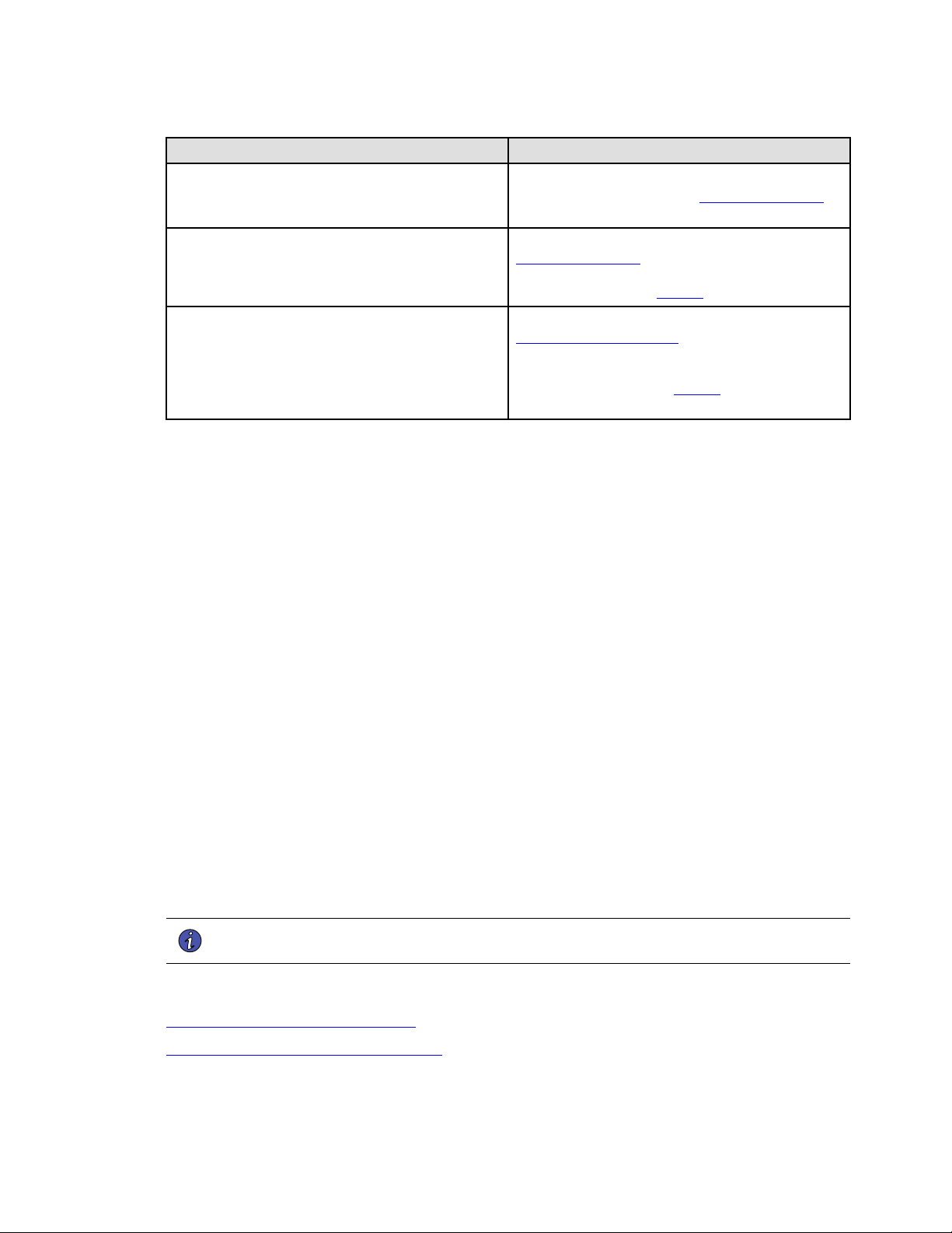
106 4–20kVA Users Guide P-164000669 4–20kVA Users Guide P-164000669—Rev 10
Question: how do I... Answer
Change the batteries?
Each pair of battery modules of a two-battery slot forms one
series slot on the battery bus. See “9.4 Battery Replacement ”
for the battery replacement procedure.
Add/delete one or more slots of batteries?
Physically install or remove battery modules as described in “
9.4 Battery Replacement” . If not using a 9PXM EBM, record the
capacity of external battery slots (in all external battery
cabinets) by going to menu Figure 61.
dd/delete one or more power modules?
Physically install or remove power modules as described in “
9.5 Power Module Replacement ”. The system operating
software senses the number and location of all power modules
in the cabinet. If you want to change the number of redundant
power modules, go to menu in Figure 64 and change the level
of system redundancy.
1111..22 SSeerrvviiccee aanndd SSuuppppoorrtt
If you have any questions or problems with the UPS, call your Local Distributor or the Help Desk at one of the
following telephone numbers and ask for a UPS technical representative.
United States:
1–800–356–5737
Canada:
1–800–461–9166 ext 260
All other countries: Call your local service representative
Please have the following information ready when you call the Help Desk:
• Model number
• Serial number
• Version number (if available)
• Date of failure or problem
• Symptoms of failure or problem
• Customer return address and contact information
If repair is required, you will be given a Returned Material Authorization (RMA) Number. This number must
appear on the outside of the package and on the Bill Of Lading (if applicable). Use the original packaging or
request packaging from the Help Desk or distributor. Units damaged in shipment as a result of improper
packaging are not covered under warranty. A replacement or repair unit will be shipped, freight prepaid for all
warrantied units.
NOTE For critical applications, immediate replacement may be available. Call the Help Desk for
the dealer or distributor nearest you.
1111..33 TTwwoo--YYeeaarr LLiimmiitteedd WWaarrrraannttyy
Eaton 9PXM Two-Year Limited Warranty
Eaton 9PXM UPS Load Protection Guarantee
Service and Support

4–20kVA Users Guide P-164000669 4–20kVA Users Guide P-164000669—Rev 10 107
Two-Year Limited Warranty

P-16400066910
P-164000669 10