ANNKE
IP Camera User Manual
Ver.202304

1
Thank you very much for choosing ANNKE.
Our products are supported by the world's first video monitoring manufacturers,
and they have adopted military level of protection. It is our top priority to ensure your
data safety and offer you a satisfactory service. We strongly recommend that you set up an
appropriate password for your device and save it, also set up security questions and
reserved email to ensure you can reset password by yourself.
Please download ANNKE App, Client software and user manuals from our download center:
https://www.annke.com/pages/download-center
If you have any questions, please feel free to email us at support@annke.com.
Or visit our help center: help.annke.com.
Free call for US and CA, +1 833 717 0187

2
Content
1.Introduction ..................................................................................................................................... 3
1.1 Activation and Login ............................................................................................................. 3
1.1.1 Activation ...................................................................................................................3
1.1.2 Login ...........................................................................................................................4
1.2 Installing the plug-in ............................................................................................................. 4
2. Live View ........................................................................................................................................ 5
3. Playback .......................................................................................................................................... 9
4. Picture ........................................................................................................................................... 10
5. Configuration ................................................................................................................................ 10
5.1 Local Configuration .............................................................................................................10
5.2 System.................................................................................................................................12
5.2.1 System settings ........................................................................................................12
5.2.2 Maintenance ............................................................................................................15
5.2.3 Security .................................................................................................................... 17
5.2.4 User Management ...................................................................................................17
5.3 Network .............................................................................................................................. 19
5.3.1 Basic Settings ........................................................................................................... 19
5.3.2 Advanced Settings ................................................................................................... 22
5.4 Video/Audio........................................................................................................................ 29
5.5 Image .......................................................................................................................... 33
5.6 Event................................................................................................................................... 38
5.6.1 Motion Detection .................................................................................................... 38
5.6.2 Video Tampering ......................................................................................................41
5.6.3 Alarm Input ..............................................................................................................42
5.6.4 Alarm Output ...........................................................................................................42
5.6.5 Exception ................................................................................................................. 43
5.6.7 Flashing Alarm Light Output ....................................................................................43
5.6.8 Audible Alarm Output ............................................................................................. 44
5.6.9 Video Quality Diagnosis ...........................................................................................44
5.6.10 PIR Alarm ............................................................................................................... 45
5.6.11 Audio Exception Detection ....................................................................................45
5.6.12 Defocus Detection ................................................................................................. 46
5.6.13 Scene Change Detection ........................................................................................46
5.6.14 Face Detection ....................................................................................................... 47
5.6.15 Line Crossing Detection ......................................................................................... 47
5.6.16 Intrusion Detection ................................................................................................48
5.6.17 Region Entrance Detection ....................................................................................49
5.6.18 Region Exiting Detection ....................................................................................... 51
5.6.19 Unattended Baggage Detection ............................................................................ 52
5.6.20 Object Removal Detection .....................................................................................53
5.7 Storage................................................................................................................................ 53
5.8 Face capture ........................................................................................................................57
3
1.Introduction
1.1 Activation and Login
1.1.1 Activation
To protect the security and privacy of the user account and data, you have to activate the
camera and create a password before you can do any operation.Four activation methods are
supported: Activation via Web Browser, Activation via SADP, and Activation via client software
Guarding Vision, Activation via Mobile APP ANNKE Vision.
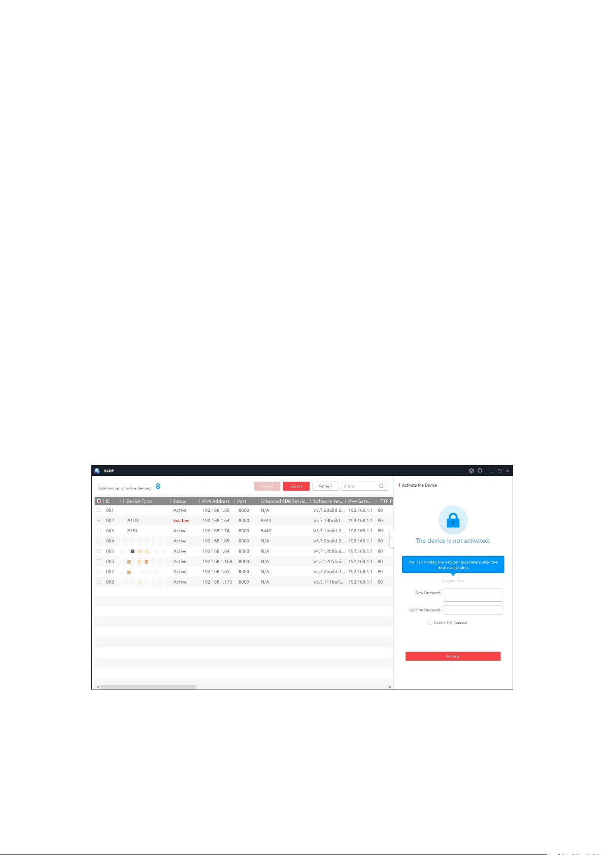
We will take Activation via SADP as an example to introduce the camera activation. SADP is a
software detects the online device, activates the camera, and resets the password. Get the SADP
software from the official website https://www.annke.com/pages/download-center, and
install the SADP according to the prompts. Follow the steps below to activate the camera.
Steps:
1. Make sure your device and your PC connect to the same LAN. Then run the SADP to search
the online devices.
2. Check the device status from the device list, and select the inactive device.
3. Create a password and enter the password in the password field, and confirm the password.
Notes:
1. The system judges password strength automatically, and we highly recommend you use a
strong password to ensure your data security. A strong password ranges from 8 to 16
characters, and must contain at least three of the following categories: numbers, lower
cases, upper cases and special characters. Password can not included user name.
4
2. The password can not contain user name.
3. After activation, you can set security questions and email for password recovery (skip if not
needed). Click Forget Password on login page and follow pop-up instructions to complete
operation. Note that when resetting the admin password, the device and the PC must
belong to the same IP address segment of the same LAN.
4. Click OK to save the password.
5. Change the device IP to the same sub net with your computer by either modify the IP
address manually or check the checkbox of Enable DHCP.
6. Enter the password to activate your IP address modification.
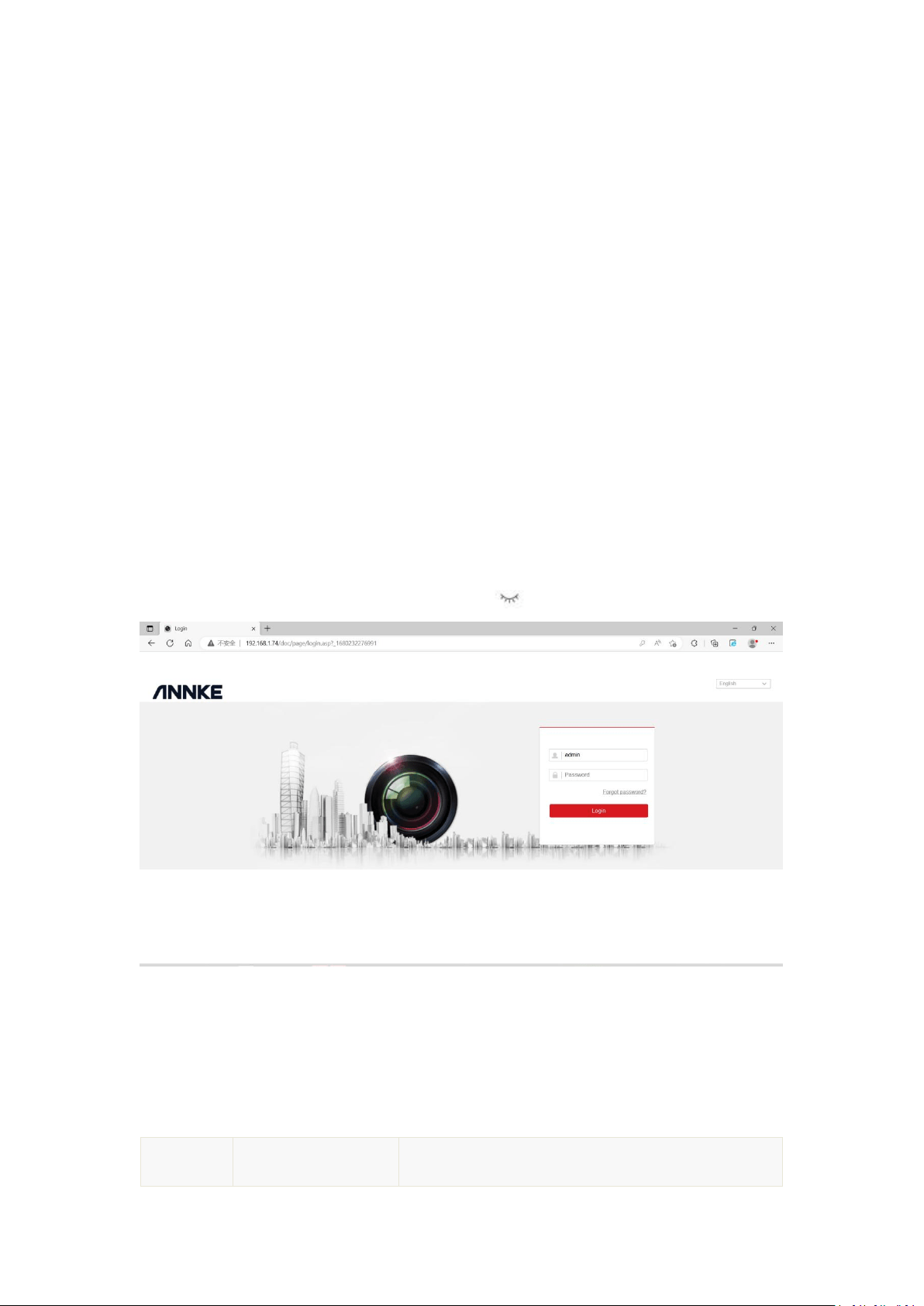
1.1.2 Login
After you activate the device and and get the IP address, you can access the device via web
browser.
Steps:
1. Open the web browser and enter the IP address of the device in the address bar, e.g.,
192.168.1.64, and then press the Enter key to enter the login interface.
2. Select the language on the top-right of login interface.
3. Enter the user name and password,and click Login.
Note: When you are entering password, you can click to show password.
1.2 Installing the plug-in
Certain operation system and web browser may restrict the display and operation of the camera
function. You should install plug-in or complete certain settings to ensure normal display and
operation.
Operation
System
Web Browser
Operation
5
Windows
Internet Explorer 8+
Google Chrome 57 and
earlier version
Mozilla Firefox 52 and
earlier version
Follow pop-up prompts to complete plug-in installation.
Google Chrome 57+
Mozilla Firefox 52+
Click to download and install
plug-in.
Mac OS
Google Chrome 57+
Mozilla Firefox 52+
Mac Safari 16+
Plug-in installation is not required.
Enable WebSocket or WebSockets (Configuration >
Network > Advanced Settings > Network Service) for
normal live view.
Display and operation of certain functions are
restricted. For example, Playback and Picture are not
available. For detailed restricted function, refer to the
actual device.
Note: The camera only supports Windows and Mac OS system and do not support Linux system.
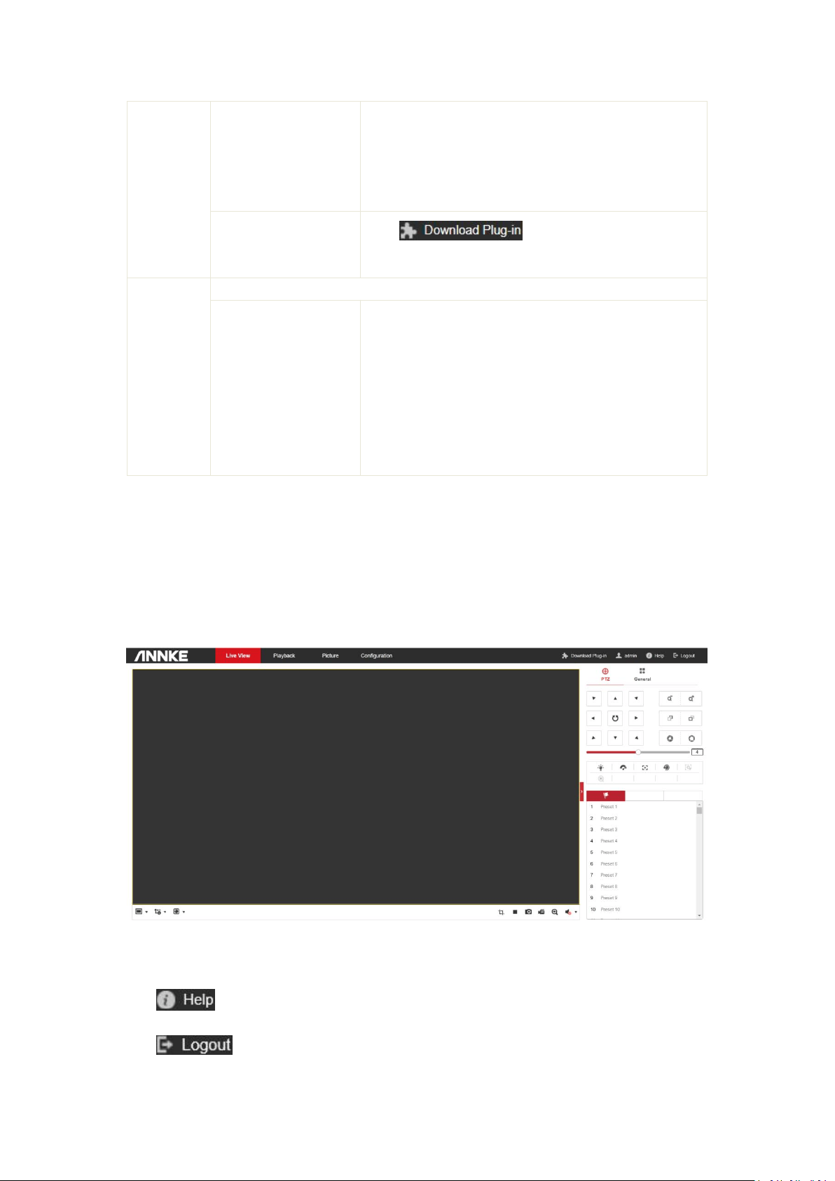
2. Live View
The live view page allows you to view the real-time video, capture images, realize PTZ control,
set/call presets and configure video parameters.
Menu Bar:
Click each tab to enter Live View, Playback, Picture and Configuration page respectively.
Click to read operation instructions.
Click to exit the device.
6
Live View Window:
Display the live video.
Toolbar: Operations on the live view page, e.g., live view, capture, record, audio on/off, two-way
audio, etc.
Live View Parameters: Configure the image size and stream type of the live video.
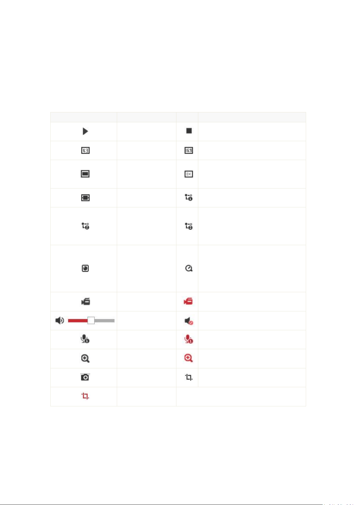
Descriptions of the Icons on the Live View Page
The functions of the buttons on the toolbar are shown in the following table.
Button
Description
Button
Description
Start live view.
Stop live view.
The window size is
4:3.
The window size is 16:9.
The window size is
the original aspect
ratio.
The original window size.
Self-adaptive window
size.
Live view with the main stream.
Live view with the
sub stream.
Live view with the third stream. For the
camera models that support 10 streams,
you should go to Video/Audio > Custom
Video to add the streams.
Play via
Webcomponents.
Play via QuickTime. The displayed
plug-in may vary with the camera
model. Certain browsers support
Webcomponents, QuickTime,VLC and
MJPEG.
Manually start
recording.
Manually stop recording.
Audio on and adjust
the volume.
Mute
Start two-way audio.
Stop two-way audio.
Start digital zoom.
Stop digital zoom.
Manually capture the
picture.
Enable Pixel Counter.
Disable Pixel Counter.
Note:
The toolbar icons on the live view page vary depending on different camera models.
Digital Zoom:
1. Click Start Digital Zoom button to enable the function.

7
2. Click the mouse on the chosen PTZ view and drag it to a lower right position. The area in the
red rectangle will be zoomed in after you loose the mouse.
3. Click the mouse on the zoomed-in PTZ view, drag it to a higher left position and loosen the
mouse to zoom out.
4. Click Disable Stop Digital Zoom button to stop the function.
Pixel Counter:
1. Click Start Pixel Counter button to enable the function.
2. Drag the mouse on the image to select the desired rectangle area. The width pixel and
height pixel is displayed on the bottom of the web.
3. Click the button again to stop the function.
Note: The pixel counter is only supported under the main stream and only one rectangle are
supported.
Full-screen Mode:
You can double-click on the live video to switch the current live view into full-screen or return to
normal mode from the full-screen.
Main stream/Sub-stream/Third stream:
You can select Main Stream, Sub-Stream or Third Stream as the stream type of live view. The
main stream is with a relatively high resolution and needs much bandwidth. The sub-stream is
with a low resolution and needs less bandwidth. The resolution of third stream is between that
of main stream and sub stream. The default setting of stream type is Main Stream.
Image Size:
You can scale up/down the live view image by clicking , the image size can
be 4:3, 16:9, original, original ratio, or auto.
Recording and Capturing Pictures Manually:
In the live view interface, click on the toolbar to capture the live pictures or click to
record the live video. The local saving paths of the captured pictures and clips can be set in
the Configuration > Local Configuration interface. To configure remote automatic recording,
refer to Storage section.
Note: The captured image will be saved as a JPEG or BMP file in your computer.
Live View Quick Setup
It allows quick setup of image/video related parameters on live view page.
Steps:
1. Click button on the right of the live view window to show the PTZ control panel. Click to
hide it.
2. Specify PTZ, Display, OSD and Video/Audio and VCA resource parameters. For more settings,
go to Configuration -> Image and Configuration -> Video/Audio.
Display Settings
Scene: Select a scene according to actual installation environment.(Only certain camera models
support.)
WDR: The WDR (Wide Dynamic Range) function helps the camera provide clear images even
under back light circumstances. When there are both very bright and very dark areas
8
simultaneously in the field of view, WDR balances the brightness level of the whole image and
provide clear images with details. You can enable or disable the WDR function and set the level.
HLC: High Light Compensation makes the camera identify and suppress the strong light sources
that usually flare across a scene. This makes it possible to see the detail of the image that would
normally be hidden.
OSD: Set text information displayed on screen. Alignment adjustment is available for Text Overlay.
Save the settings after configuration.
Video/Audio: Resolution and Max. Bit rate are adjustable. Click to change stream.
VCA Resource: VCA Resource offers options to enable certain VCA functions and hide others. It
helps allocate more resources to the wanted functions. A reboot is required after setting the VCA
Resource.
Note:
1. VCA Resource function varies according to different camera models.
2. VCA options are mutually exclusive.
3. The function may not be supported by some camera models.
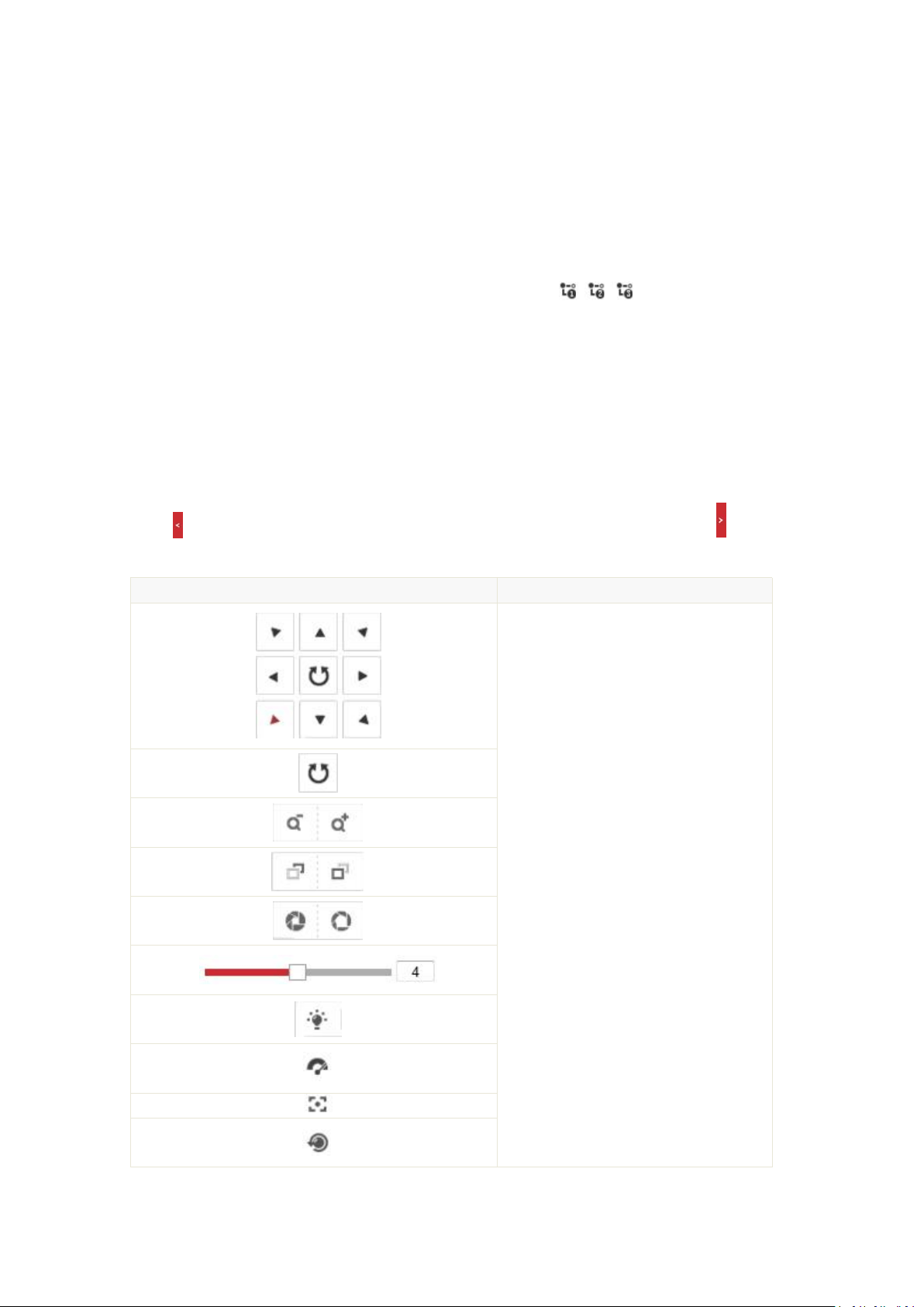
Descriptions of the Icons on the PTZ Page
Click button on the right of the live view window to show the PTZ control panel. Click to hide
it.
Button
Description
Direction Button
Start/Stop Auto-scan
Zoom -/Zoom +
Focus -/Focus +
Iris -/Iris +
PTZ Speed Adjustment
Enable/Disable Light
Enable/Disable Wiper
Auxiliary Focus
Len Initialisation
9
Start Manual Tracking
Start 3D Zoom
Preset
Patrol
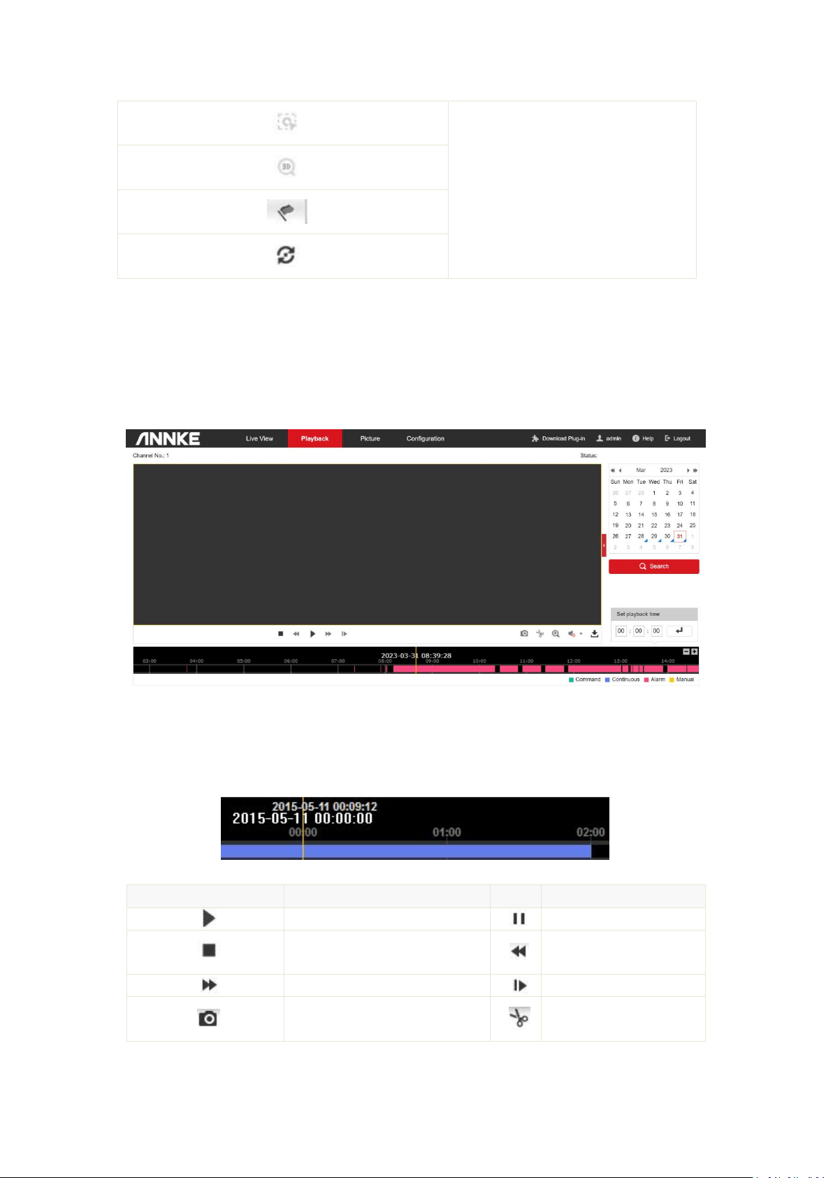
3. Playback
This section explains how to view the remotely recorded video files stored in the network disks
(NAS) or memory cards.
Steps:
1. Click Playback tab to enter the playback interface.
2. Select a date and click Search to search the record files.
3. The matched results will be displayed as follows.
The description of the icons on the playback interface is shown below.
Button
Description
Button
Description
Play.
Pause.
Stop.
Slow forward.
Fast forward.
Playback by frame.
Capture picture.
Start clipping video files.
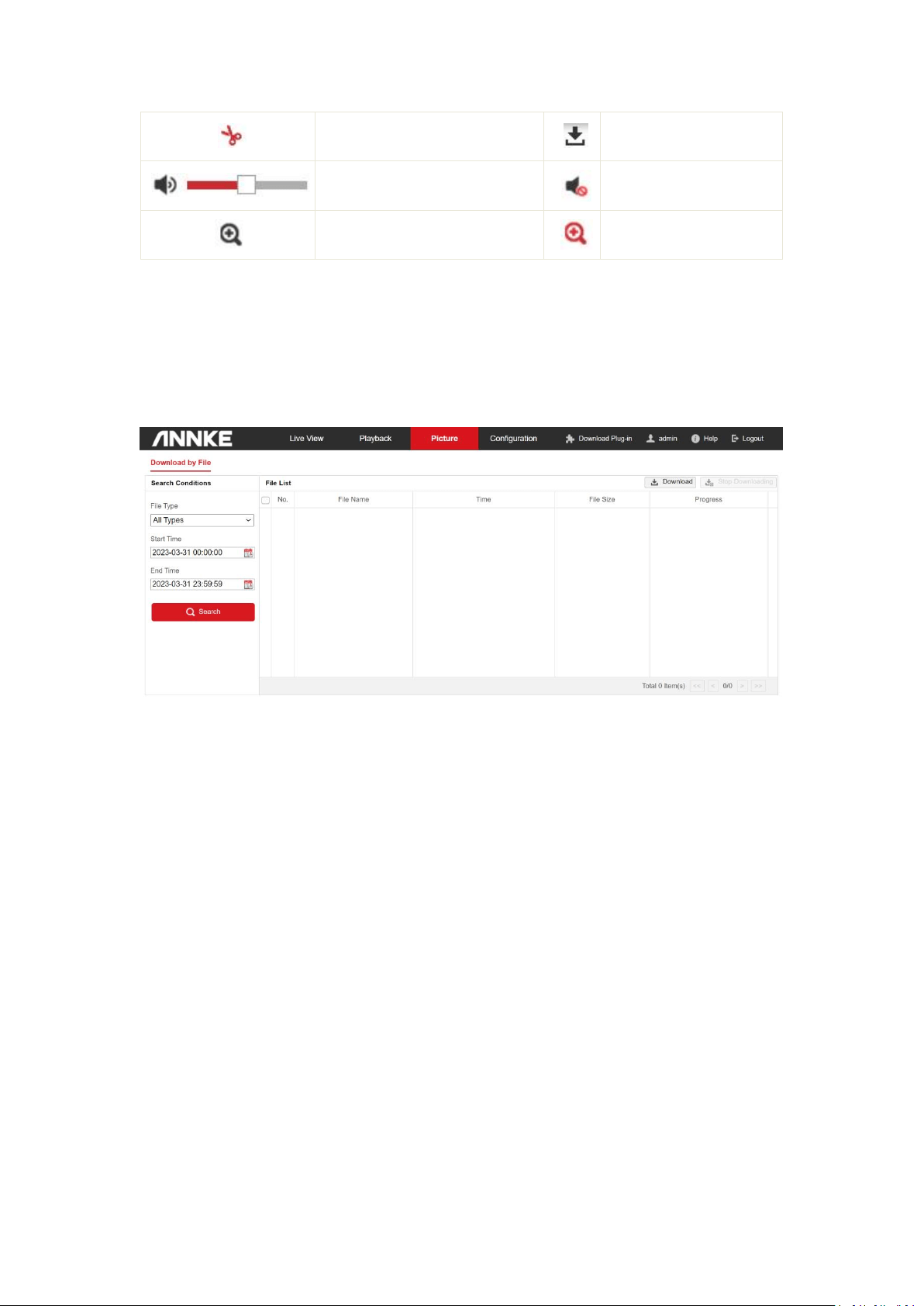
10
Stop clipping.
Download recording files.
Audio on and adjust the volume.
Mute.
Start digital zoom.
Stop digital zoom.
4. Picture
Click Picture tab to enter the picture search interface. You can view, search, and download the
pictures saved on local storage or NAS.
1. Select the search conditions, including the picture type, start time, and end time, then click
Search. The results will be listed on the picture list area.
2. Select one picture and click Preview to preview the picture.
3. Check the checkbox of each picture, and click Download to download the selected pictures.
Note: Configure the saving path from Configuration > Local Configuration > Save snapshots in live
view to.
5. Configuration
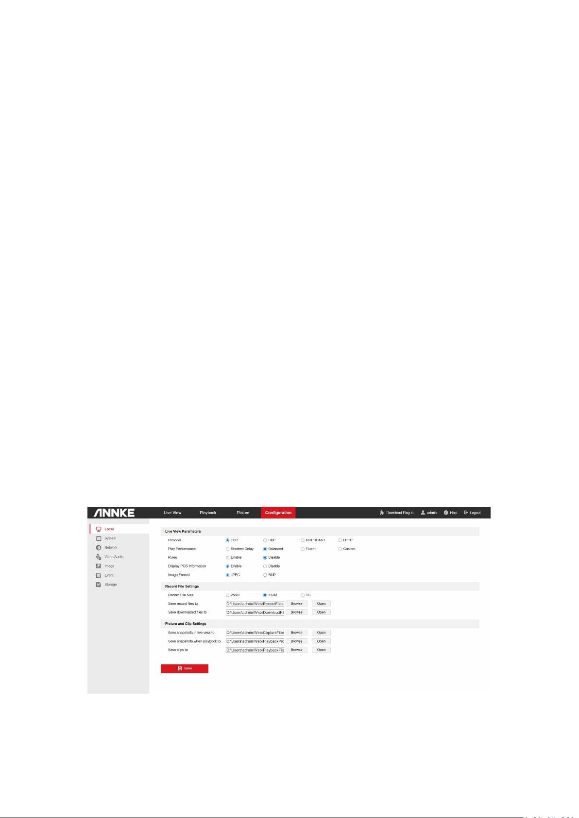
5.1 Local Configuration
Local configuration allows you to configure the live view parameters, including the protocol, live
view performance, rules, image format, etc., record files Settings, and the picture and clip
settings.
Protocol: TCP, UDP, MULTICAST and HTTP are selectable.
11
TCP ensures complete delivery of streaming data and better video quality, yet the real time
transmission will be affected. It is suitable for the stable network environment.
UDP is suitable for the unstable network environment that does not demand high video fluency.
MULTICAST is suitable for the situation that there are multiple clients. You should set the
multicast address for them before selection.
HTTP is suitable for the situation that the third-party needs to get the stream from the
device.
Play Performance: Select the different live view effects according to your actual bandwidth. For
Custom, you can set the frame rate for live view.
Shortest Delay: The device takes the real time video image as the priority over the video fluency.
Balanced:The device ensures both the real time video image and the fluency.
Fluent:The device takes the video fluency as the priority over real time. In poor network
environment, the device cannot ensures video fluency even the fluency is enabled.
Custom: You can set the frame rate manually. In poor network environment, you can reduce the
frame rate to get fluent live view. But the rule information may cannot display.
Rules: It gives you options to display or do not display the green rectangles when the motion
detection, face detection, or intrusion detection is triggered.
Display POS Information: Enable the function, feature information of the detected target is
dynamically displayed near the target in the live image.
Image Format: Refers to the saving format of the captured pictures.
Record File Settings and Picture and Clip Settings allow you to select the file size,and saving path
of the recorded files/snapshots/clips. Click Browse to view and select a folder. Click Open to
open the set folder.

12
5.2 System
5.2.1 System settings
Basic Information
The basic information interface allows you to check the basic information of the network camera,
including the Model, Serial No., Firmware Version, Encoding Version, Number of Channels,
Number of HDDs, Number of Alarm Input, Number of Alarm Output, Firmware Version Property,
etc. The information cannot be changed in this menu. It is the reference for maintenance or
modification in future.
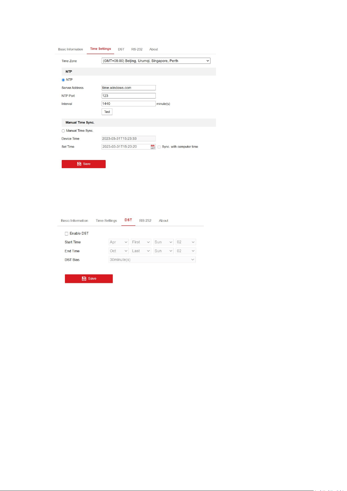
Time Settings
Follow the steps below to configure the time synchronization.
1. Go to Time Settings interface.
2. Select the Time Zone of your location from the drop-down menu.
Time Synchronization by NTP Server
You can check the checkbox to enable the NTP function, and configure the server address, NTP
Port, and the Interval, which is the time interval between the two synchronizing actions with NTP
server.
Note: If the camera is connected to a public network, you should use a NTP server that has a
time synchronization function, such as the server at the National Time Center (IP Address:
210.72.145.44). If the camera is set in a customized network, NTP software can be used to
establish a NTP server for time synchronization.
Time Synchronization Manually
Enable the Manual Time Sync function and then click to set the system time from the pop-up
calendar.
Note: You can also check the Sync with computer time checkbox to synchronize the time of the
camera with that of your computer. Define the quota for record and pictures.
3. Click Save to save the settings.
13
DST
Check the Enable DST checkbox to enable DST (Daylight Saving Time).
Select the start time,end time, and DST Bias, and click Save to activate the settings.
RS485
Note: The function is only supported by certain camera models.
The RS-485 serial port is used to control the PTZ of the camera. The configuring of the PTZ
parameters should be done before you control the PTZ unit.
By default, the default baud rate is set as 9600 bps, the Data Bit is 8, the stop bit is 1 and the
Parity and Flow Control is None.
RS232
The RS-232 port can be used in two ways:
Console: Connect a computer to the camera through the serial port. Device parameters can be
configured by using software such as Hyper Terminal. The serial port parameters must be the
same as the serial port parameters of the camera.
Transparent Channel: Connect a serial device directly to the camera. The serial device will be
controlled remotely by the computer through the network.
14
About
Click View License,and you can check Open Source Software Licenses.
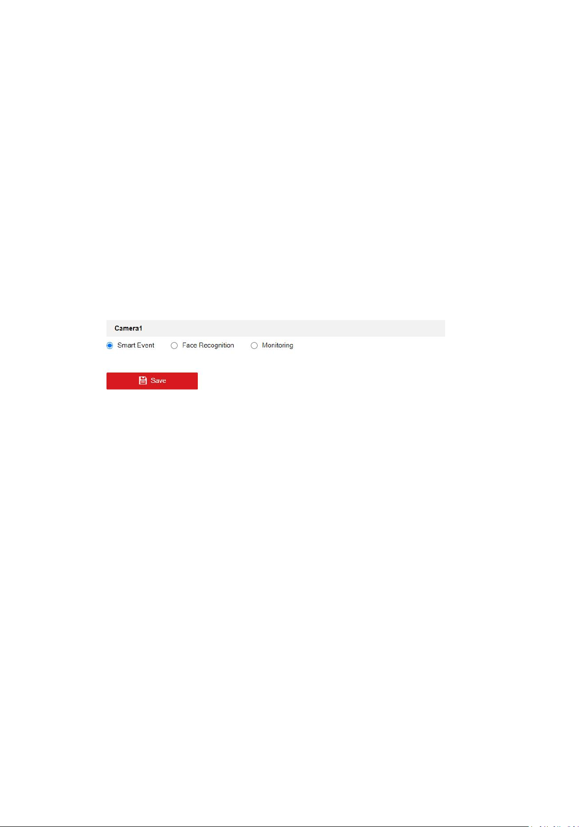
VCA Resource
Note: The function is only supported by certain camera models.
VCA Resource offers options to enable certain VCA functions and hide others. It helps allocate
more resources to the wanted functions. A reboot is required after setting the VCA Resource.
1. Enter the VCA Resource interface.
2. Select a desired VCA combination.
3. Click Save to save the settings. A reboot is needed for the settings to take effect.
Notes:
1. After rebooting, the interface may changes according to the selected VCA Resource.
2. VCA Resource function varies according to different camera models.
3. VCA options are mutually exclusive.
4. The function may not be supported by some camera models.
Metadata Settings
Metadata is the raw data the camera collects before algorithm processing. If enabled, the
metadata of the corresponding event are available for users to explore the possibility of various
data usage.
Note: The function is only supported by certain camera models.
1. Enter the Metadata settings interface.
2. Check the checkbox of the corresponding function to enable the metadata function.
The metadata of the smart event includes the target ID, target coordinate and time
information.
The metadata of face capture includes the rule information, target ID, target coordinate,
face grading and time information. The camera detects the whole image by default. If the region
is configured in the face capture settings, the camera detects the configured region.
3. Check Enable Stream Rule to overlay the stream rule on the live view image. Make sure you
have checked Sub-stream and selected the Sub-stream in the live view.
4. Check Overlay Rule Frame and Target Frame on Background Picture to enable the function.
Make sure you have checked Sub-stream and selected the Sub-stream in the live view.

15
5.2.2 Maintenance
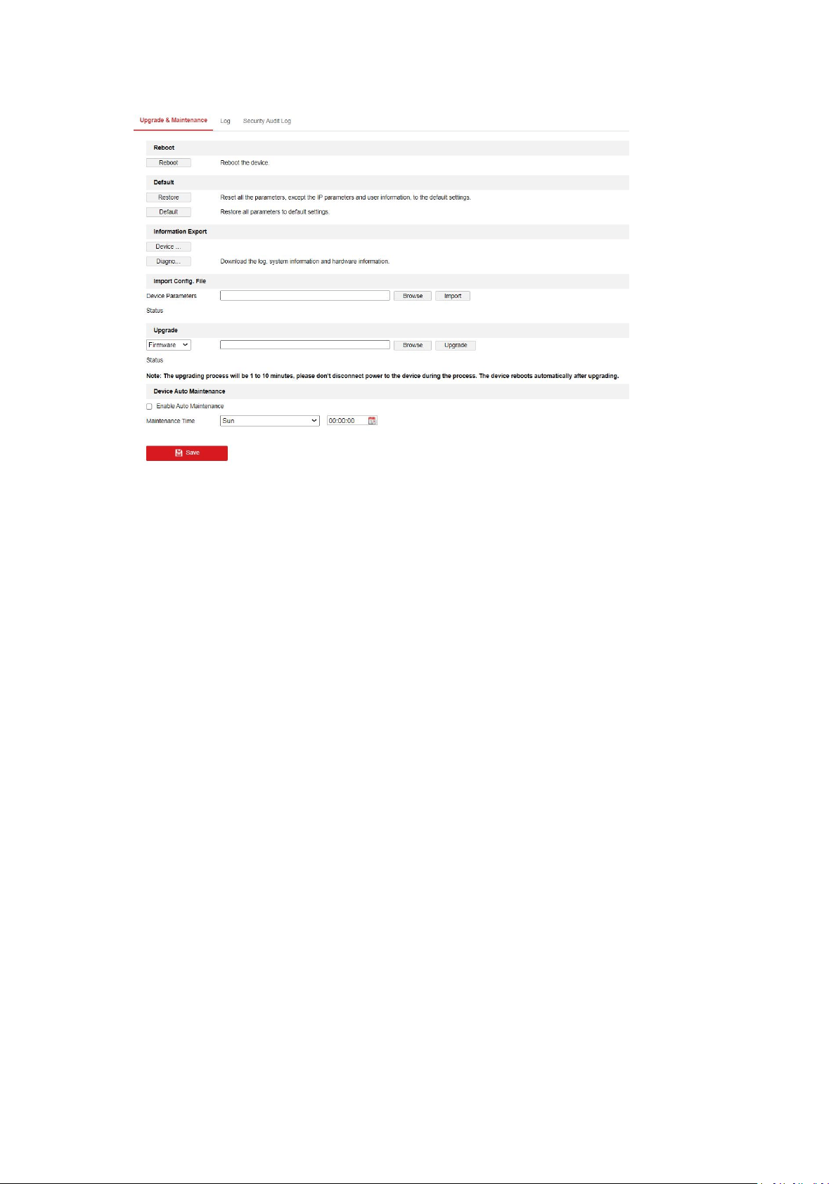
Upgrade&Maintenance
Rebooting the Camera
Go to the camera reboot interface, and click Reboot to reboot the network camera.
Restoring Default Settings
Go to the camera restore interface, and click Restore or Default to restore the default settings.
After Default action,the IP address is also restored to the default IP address, please be careful for
this action.
Note: For the camera that supports Wi-Fi, wireless dial, or wlan function, Restore action does not
restore the related settings of mentioned functions to default.
Information Export
Go to the information export interface. Click Device Parameters and set the the encryption
password to export the current configuration file. Set the saving path to save the configuration
file in local storage. Click Diagnose Information to download the log and system information.
Importing Configuration Files
Go to the import interface. Click Browse to select the saved configuration file, input the
encryption password,and then click Import to start importing configuration file.
Upgrading the System
For better user experience, we recommend you to update your device to the latest firmware
asap. Please get the latest firmware package from the official website .Go to the upgrade
interface, and click Browse to select the local upgrade file and then click Upgrade to start remote
upgrade.
Device Auto Maintenance
Go to the device auto maintenance interface. Check Enable Auto Maintenance and set
maintenance time. If enabled, the device will automatically restart according to the maintenance
plan and the device cannot record video during restart.
16
Log
The log interface provides you the options to check and export the log files of operation, alarm,
and exception information of the camera. Before you view or export the log information, please
make sure the network storage of the camera is configured, or the local storage (memory card) is
working.
Steps:
1. Go to log searching interface.
2. Set the log search conditions to specify the search, including the Major Type, Minor Type,
Start Time and End Time.
3. Click Search to search log files. The matched log files will be displayed on the Log interface.
4. To export the log files, click Export to save the log files in your computer.
Security Audit Log
Note: The function is only supported by certain camera models.
The security audit logs refer to the security operation logs. You can search and analyze the
security log files of the camera so that to find out the illegal intrusion and troubleshooting the
security events.
Security audit logs can be saved on device flash. The log will be saved every half hour after device
booting.
Due to limited saving space of the flash, you can also save the logs on a log server. Configure the
server settings at Advanced Settings.
Searching Logs
1. Set the log search conditions to specify the search, including the Major Type, Minor
Type, Start Time and End Time.
2. Click Search to search log files. The matched log files will be displayed on the Log list
interface.
3. To export the log files, click Export to save the log files in your computer.

17
Setting Log Server
1. Check Enable Log Upload Server.
2. Enter Log Server IP and Log Server Port.
3. Click Test to test settings.
4. Install certificates. Client certificate and CA certificate are required.
Client Certificate
1.Click Create button to create the certificate request. Fill in the required information in
the popup window.
2.Click Download to download the certificate request and submit it to the trusted
certificate authority for signature.
3.Install the signed certificate to the device.
CA Certificate
Install the CA certificate to the device.
5.2.3 Security
Authentication
You can specifically secure the stream data of live view via authentication configuration. RTSP
authentication and WEB authentication are supported.
1. Enter the authentication configuration interface.
2. Select the authentication type. Digest is the recommended safer authentication way.
3. Click Save to save the settings.
IP Address Filter
Note: The function is only supported by certain camera models.
IP address filter makes it possible for access control. you can enable the IP address filter to allow
or forbid the visits from the certain address.
Security Service
Check the checkbox of Enable SSH to enable the data communication security, and uncheck the
checkbox to disable the SSH.
Check the checkbox of Enable Illegal Login Lock to stop the illegal login. And then set the Illegal
Login Attempt time as required.
Advanced Security
Note: The function is only supported by certain camera models.
Advanced security offers options to manage network security settings of the device
5.2.4 User Management
As Administrator
18
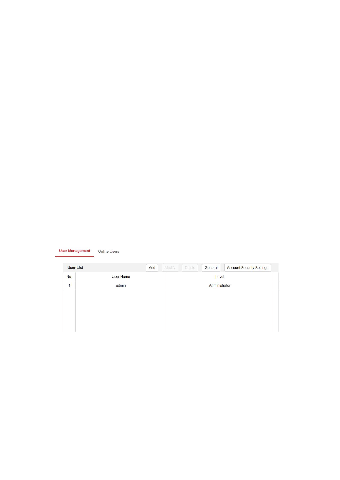
The administrator can add, delete or modify user accounts, and grant them different permissions.
We highly recommend administrator to manage the device accounts and user permissions
properly. Up to 31 user accounts can be created.
The administrator can click General to set the Simultaneous Login for the camera. If the number
of the simultaneous login exceeds the set threshold, your access will be denied.
The administrator need to input correct admin password when changing settings of other
operators or users.
Administrator can setup Account Security Settings for password recovery. Recovering via
security questions and via email are available.
Security Question: Select 3 questions and input answers.
Password Recovery via E-mail: Input your email address to receive verification code.
Follow instructions on login page to reset password. Note that when resetting the password, the
PC the administrator uses and the camera should belong to the same IP address segment of the
same LAN.
As Operator or User
Operator or user can modify password. Old password is required for this action.
Password Recommendation
The system judges the password strength automatically when creating the password. A strong
password is highly recommended to ensure your data security. And a strong password should be
your own choosing (using a minimum of 8 characters, including at least three of the following
categories: upper case letters, lower case letters, numbers, and special characters).
The password can not contain user name.
Online Users
You can see the current users who are visiting the device through this interface. User information,
such as user name, level, IP address, and operation time, is displayed in the User List. Click
Refresh to refresh the list.
Note: This function may not be supported by certain camera models.

19
5.3 Network
5.3.1 Basic Settings
TCP/IP
TCP/IP settings must be properly configured before you operate the camera over network. The
camera supports both the IPv4 and IPv6. Both versions may be configured simultaneously
without conflicting with each other, and at least one IP version should be configured.
1. Click TCP/IP tab to enter the TCP/IP configuration interface.
2. For the cameras support Wi-Fi, there are two NIC tabs selectable. One for LAN and the other
one for WLAN. Click the tab to configure the parameters of the selected NIC.
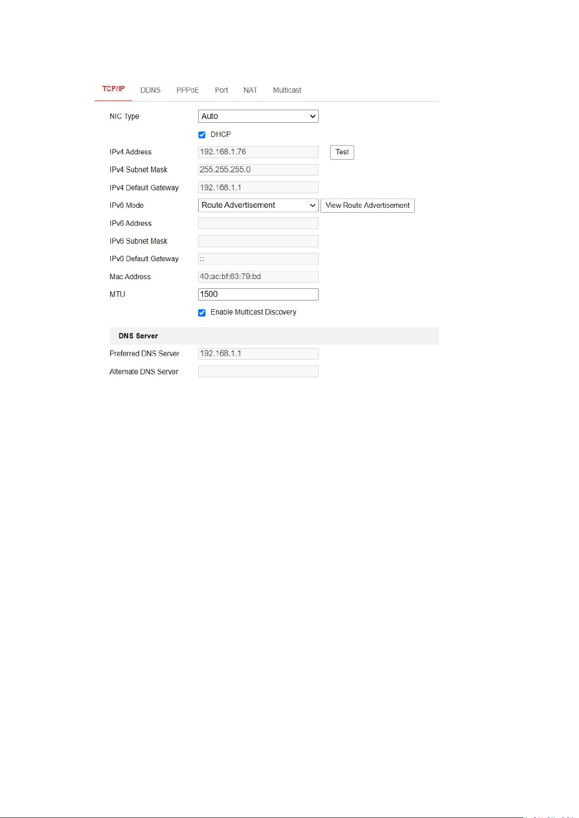
3. Configure the basic network settings, including the NIC Type, IPv4 or IPv6 Address, IPv4 or
IPv6 Subnet Mask, IPv4 or IPv6 Default Gateway, MTU [1280~1500] settings and Multicast
Address.
NIC Type: Select a NIC (Network Interface Card) type according to your network condition
IPv4:Two IPv4 modes are available.
DHCP: The device automatically gets the IPv4 parameters from the network if you check
DHCP. The device IP address is changed after enabling the function. You can use SADP to get
the device IP address.
Manual:You can set the device IPv4 parameters manually. Input IPv4 Address, IPv4 Sub net
Mask, and IPv4 Default Gateway, and click Test to see if the IP address is available.
IPv6: Three IPv6 modes are available.
MTU:It stands for maximum transmission unit. It is the size of the largest protocol data unit
that can be communicated in a single network layer transaction. The valid value range of
MTU is 1280 to 1500.
4. (Optional) Check the checkbox of Enable Multicast Discovery, and then the online network
camera can be automatically detected by client software via private multicast protocol in the
LAN.
Multicast Discovery:Check the Enable Multicast Discovery, and then the online network
camera can be automatically detected by client software via private multicast protocol in the
LAN.
5. (Optional) If DNS is required, input the address of Preferred DNS Server and Alternate DNS
Server.
DNS:It stands for domain name server. It is required if you need to visit the device with
domain name. And it is also required for some applications (e.g., sending email). Set
Preferred DNS Server and Alternate DNS server properly if needed.
6. (Optional) If Dynamic Domain Name is required, check the checkbox to enable the function,
and input the preferred domain name.
Dynamic Domain Name: Check Enable Dynamic Domain Name and input Register Domain
Name. The device is registered under the register domain name for easier management
within the local area network.
7. Click Save to save the settings.
20
Port
Port settings allow you to configure the port No. of the HTTP port, RTSP port, SRTP port, HTTPS
port, and the server port.
1. Click Port tab to enter the port configuration interface.
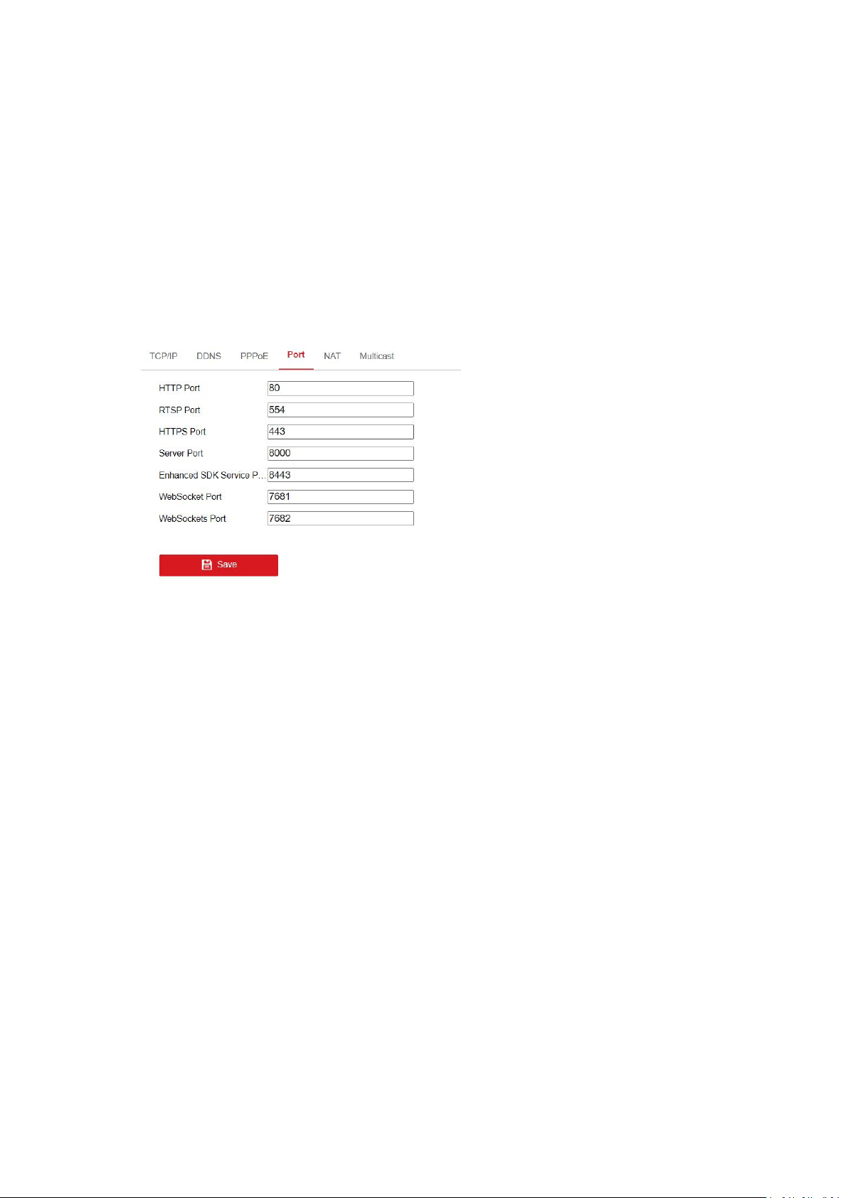
2. Set the HTTP port, RTSP port, HTTPS port and server port of the camera.
HTTP Port: The default port number is 80, and it can be changed to any port No. which is not
occupied.
RTSP Port:The default port number is 554 and it can be changed to any port No. ranges from
1 to 65535.
The correct description of rtsp is as below:
rtsp://[user name]:[password]@[ip]:[port]/[codec]/[channel]/[sub type]/av_stream
For example:
rtsp://admin:qwer1234@192.168.1.116:554/h265/ch1/main/av_stream
If the camera support ISAPI, the correct description of rtsp is as below:
rtsp://[user name]:[password]@[ip]:[port]/ISAPI/Streaming/channels/101
For example:
rtsp://admin:qwer1234@172.9.12.39:554/ISAPI/Streaming/channels/101
SRTP Port:The default port number is 322 and it can be changed to any port No. ranges from
1 to 65535.
HTTPS Port: HTTPS Port: The default port number is 443, and it can be changed to any port
No. which is not occupied.
21
Server Port: The default server port number is 8000, and it can be changed to any port No.
ranges from 2000 to 65535.
Enhanced SDK Service Port: The default server port number is 8433, and it can be changed to
any port No. ranges from 2000 to 65535.
WebSocket Port: The default port number is 7681. It can be changed to any port No. ranges
from 1 to 65535.
WebSockets Port: The default server port number is 7682. It can be changed to any port No.
ranges from 1 to 65535.
3. Click Save to save the settings.
Note: Supported ports vary according to camera models.
NAT
NAT interface allows you to configure the UPnP™ parameters.
Universal Plug and Play (UPnP™) is a networking architecture that provides compatibility among
networking equipment, software and other hardware devices. The UPnP™ protocol allows
devices to connect seamlessly and to simplify the implementation of networks in the home and
corporate environments.
1. Click NAT tab to enter the NAT configuration interface.
2. Check the checkbox to enable the UPnP™ function.
3. Select the port mapping mode. Manual and Auto are selectable. And for manual port
mapping, you can customize the value of the external port.
4. Click Save to save the settings.
DDNS
DDNS settings allow you to access the camera via the dynamic domain name server.
DynDNS
1. Enter Server Address of DynDNS (e.g. members.dyndns.org).
2. In the Domain text field, enter the domain name obtained from the DynDNS website.
3. Enter the User Name and Password registered on the DynDNS website.
4. Click Save to save the settings.
PPPoE

22
If you have no router but only a modem, you can use Point-to-Point Protocol over Ethernet
(PPPoE) function.
1. Click PPPoE tab to enter the PPPoE configuration interface.
2. Check the Enable PPPoE checkbox to enable this feature.
3. Enter User Name, Password, and Confirm password for PPPoE access. The user name and
password is assigned by your ISP.
4. Click Save to save the settings.
Multicast
You can set up active multicast on this page.
IP Address: It stands for the multicast address. The range of the multicast IP address is
224.0.0.19 to 239.255.255.255.
Video port and audio port of each video stream of each camera channel can be specified by
selecting a stream in Video Stream and inputting port number in Video Port and Audio Port.
FEC Port and FEC Ratio: Set the port and ratio of Forward Error Correction.
SRTP: The default video port is 18860 and the default audio port is 18862.
Note: Only certain camera models support FEC port, FEC ratio, and SRTP.
5.3.2 Advanced Settings
SNMP
SNMP settings is used to get the camera status, parameters and alarm related information and
manage the camera remotely when it is connected to the network.
Before setting the SNMP, please download the SNMP software and manage to receive the
camera information via SNMP port. By setting the Trap Address, the camera can send the alarm
event and exception messages to the surveillance center.
1. Click SNMP tab to enter the SNMP configuration interface.
2. Check the corresponding version checkbox to enable the feature.
3. Configure the SNMP settings.The settings of the SNMP software should be the same as the
settings you configure here.
4. Click Save to save the settings.
Note: To avoid the risk of information leakage, you are suggested to enable SNMP v3 instead of
SNMP v1 or v2.
802.1X
802.1X standard is used to secure the data. And user authentication is needed when camera is
connected to the network protected by the IEEE 802.1X.
Before you start, the authentication server must be configured. Please apply and register a user
name and password for 802.1X in the server.
1. Click 802.1X tab to enter the 802.1X configuration interface.
2. Check the Enable IEEE 802.1X checkbox to enable the feature.
3. Select the protocol. EAP-LEAP, EAP-TLS and EAP-MD5 are available.

23
4. Enter the EAPOL version. The EAPOL version must be identical with that of the router or the
switch.
5. Enter the user name and password to access the server.
6. If you set the protocol to EAP-TLS, you should enter the identify, private key password,
upload the CA certificate, user certificate and private key.
7. Click Save to save the settings.
QoS
QoS (Quality of Service) can help solve the network delay and network congestion by configuring
the priority of data sending.
1. Click Qos tab to enter the Qos configuration interface.
2. Configure the QoS settings, including video/audio DSCP, event/alarm DSCP and Management
DSCP.The valid value range of the DSCP is 0-63. The bigger the DSCP value is, the higher the
priority is.
3. Click Save to save the settings.
Email
Email function can be configured to send an email notification to all designated receivers if an
alarm event is detected, e.g., motion detection event, video loss, video tampering, etc.
Please configure the DNS Server settings on TCP/IP interface before using the Email function.
Note: The email function varies according to camera models.
1. Click Email tab to enter the email configuration interface.
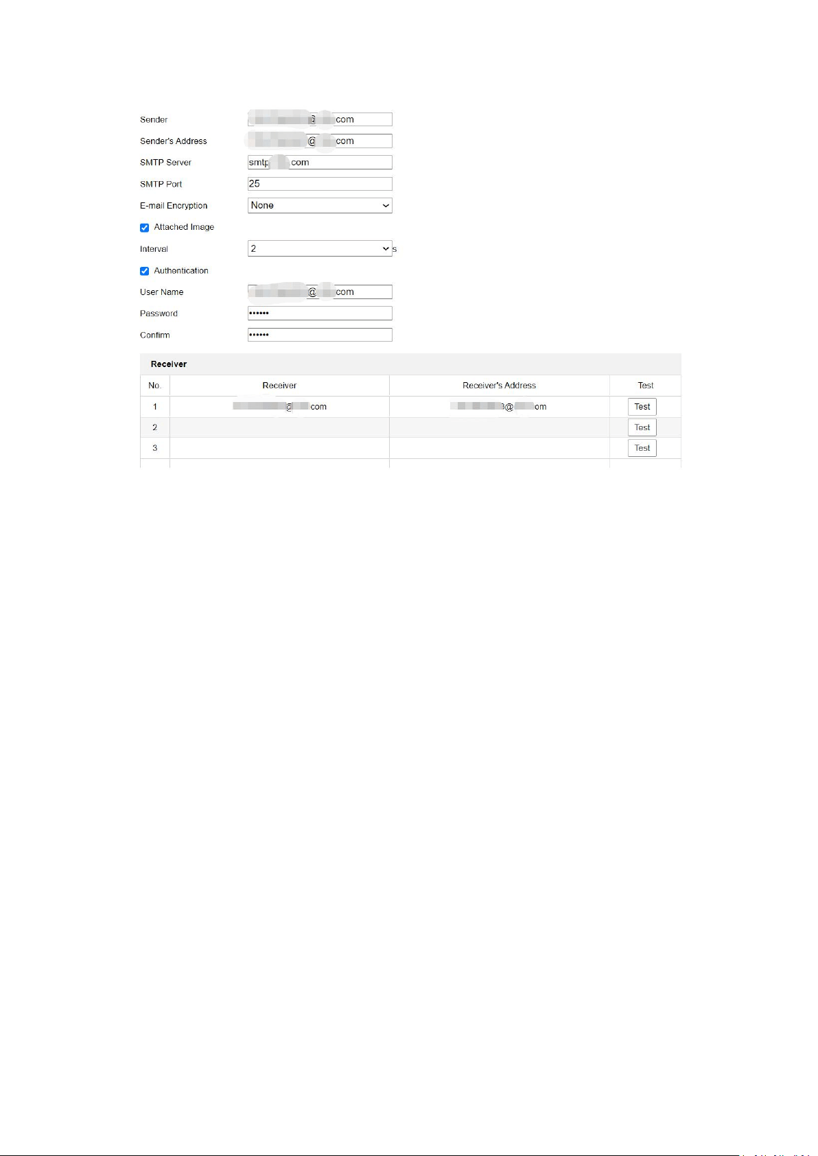
2. Configure the required information, including sender, sender's address, SMTP server, SMTP
port, E-mail Encryption, attached image, interval, authentication, receiver, receiver's address,
etc.
E-mail Encryption: None, SSL, and TLS are selectable. When you select SSL or TLS and disable
STARTTLS, e-mails will be sent after encrypted by SSL or TLS. The SMTP port should be set as
465 for this encryption method. When you select SSL or TLS and enable STARTTLS, emails will
be sent after encrypted by STARTTLS, and the SMTP port should be set as 25.
Note: If you want to use STARTTLS, make sure that the protocol is supported by your e-mail
server. If you check the Enable STARTTLS checkbox when the protocol is not supported by
your e-mail sever, your e-mail will not be encrypted.
Attached Image: Check the checkbox of Attached Image if you want to send emails with
attached alarm images.
Interval: It refers to the time between two actions of sending attached pictures.
Authentication: If your email server requires authentication, check this checkbox to use
authentication to log in to this server and enter the login user name and password.
3. Click Save to save the settings.
24
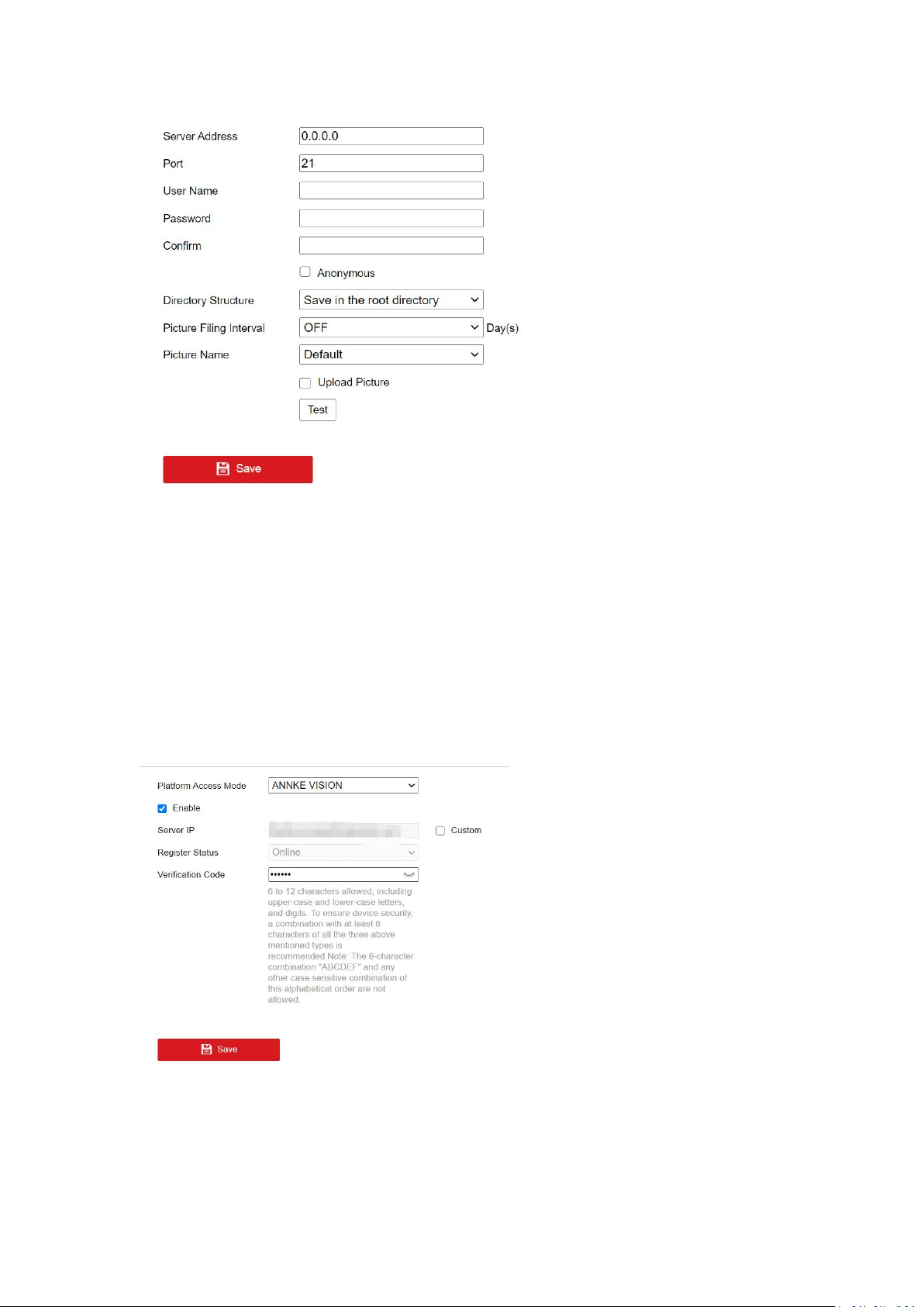
FTP
You can configure the FTP/SFTP server related information to enable the uploading of the
captured pictures to the server. The captured pictures can be triggered by events or a timing
snapshot task.
Note: The function varies according to camera models.
1. Click FTP tab to enter the configuration interface.
2. Input the address and port.
3. Input user name and password which are required for logging in the server.
4. Set the directory structure and picture filing interval.
Directory Structure: It refers to the directory in FTP/SFTP for file saving. Root directory,
parent directory and child directory are selectable. For parent directory and child directory,
you can choose an available naming rule from the drop-down list, or you can customized the
directory.
Picture Filing Interval: For better picture management, you can set the picture filing interval
from 1 day to 30 days. Pictures captured in the same time interval will be saved in one folder
named after the beginning date and ending date of the time interval.
Picture Name: Set the naming rule for captured picture files. You can choose Default in the
drop-down list to use the default naming rule, that is, "IP address_camera channel
number_capture time_event type.jpg". For example,
10.11.37.189_01_20150917094425492_FACE_DETECTION.jpg. Or you can customize the
name by adding a Custom Prefix.
5. Check the Upload Picture checkbox to enable the function.
6. Check the Automatic Network Replenishment checkbox to enable the function.
7. Click Save to save the settings.
25
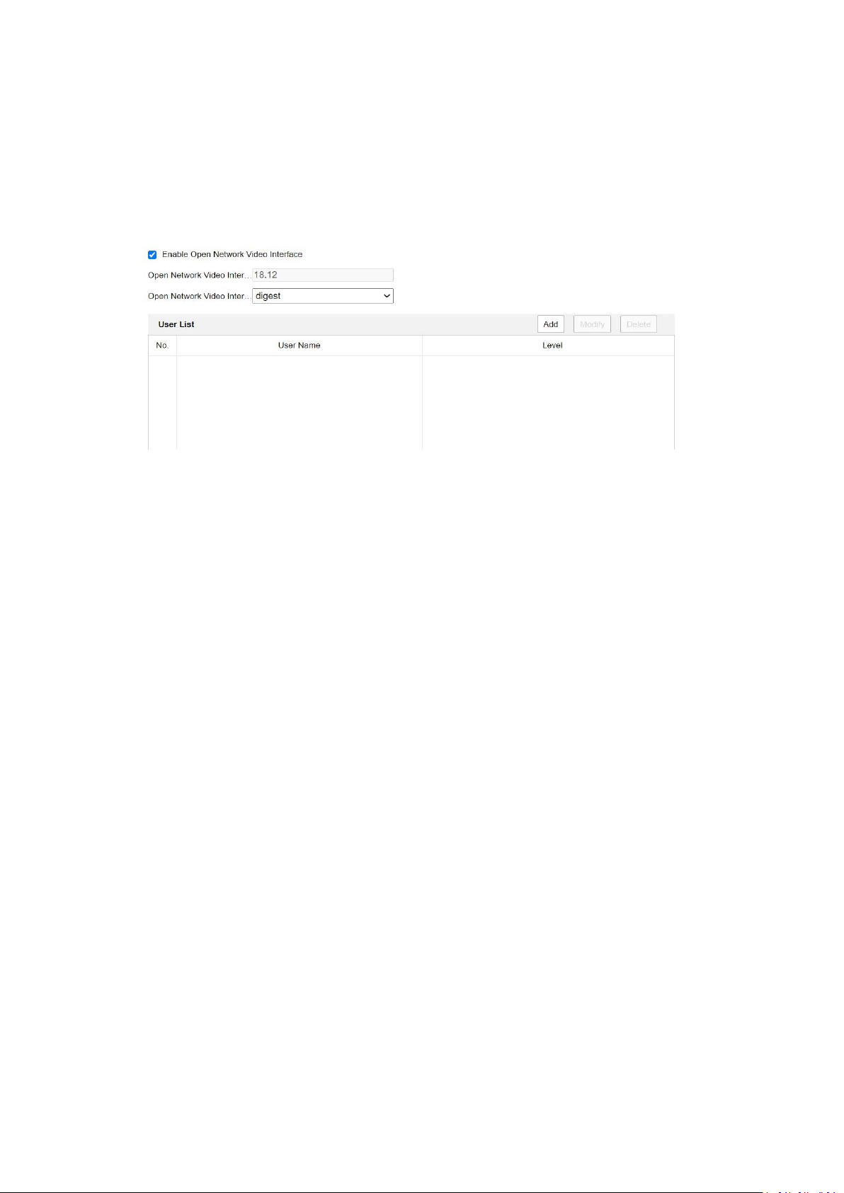
Platform Access
Platform access provides you an option to manage the devices via mobile devices.Using the App
ANNKE Vision, you can view live image, receive alarm notification and so on.
1. Enter the Platform Access settings interface.
2. Select the Platform Access Mode ANNKE Vision.
3. Check the checkbox of Enable to enable the platform access function of the device.
4. Click and read "Terms of Service" and "Privacy Policy" in pop-up window.
5. Create a verification code or change the old verification code for the camera. The
verification code is required when you add the camera to ANNKE Vision service if the image
and video Encryption function is enabled.
6. Click Save to save the settings.
After enable Platform access, you can scan the QR code below to download and install the
ANNKE Vision App, or download it from Google Play or Apple Store, then register an APP account
by your mobile number or email address, please choose the correct county/region when you
register the account.

26
For Android For iOS
Then add the device to you app account, follow the prompts to create a device password to
activate the device, enable the P2P function and create a code stream encryption verification
code, step by step until the device is added successfully.
HTTPS
HTTPS provides authentication of the web site and associated web server that one is
communicating with, which protects against Man-in-the-middle attacks.
E.g: If you set the port number as 443 and the IP address is 192.168.1.64, you may access the
device by inputting https://192.168.1.64:443 via the web browser.
Note:
For the camera that supports plug-in free live view, when you use HTTPS to visit the camera,
you should enable Websockets for live view. Go to Configuration > Network > Advanced
Settings > Network Service.
HTTPS is enabled by default. The camera creates an unsigned certificate automatically.
When you visit the camera via HTTPS, the web browser will send a notification about the
certificate issue. Install a signed-certificate to the camera to cancel the notification.
1. Enter the HTTPS settings interface.
2. Check the checkbox of Enable to enable the HTTPS function.
3. Check the checkbox of Enable HTTPS Browsing to access the camera only via HTTPS
protocol.
4. Select the server certificate.
5. Click Save to save the settings.
Note: If the function is abnormal, check if the selected certificate is abnormal in Certificate
Management.
Integration Protocol
If you need to access to the camera through the third party platform, you can enable CGI
function or Onvif protocol. And if you need to access to the device through Open Network Video
Interface protocol(Onvif), you can configure Open Network Video Interface user in this interface.
Refer to Open Network Video Interface standard for detailed configuration rules.
CGI
Check the Enable ***CGI checkbox and then select the authentication from the drop-down list.
Then you can access to the camera through the third party platform.
Open Network Video Interface
1. Check the Enable Open Network Video Interface checkbox to enable the function.
27
2. Click Add to add a new Open Network Video Interface user. Set the user name and password,
and confirm the password. You can set the user as media user, operator, and administrator.
3. Click Modify to modify the information of the added Open Network Video Interface user.
4. Click Delete to delete the selected Open Network Video Interface user.
5. Save the settings.
Note: User settings of Open Network Video Interface are cleared when you restore the camera.
Alarm Sever
Alarm information can be sent to destination IP or Host via HTTP or HTTPS or ISUP protocol.
Notes:
The function may not be supported by certain camera models.
HTTP data transmission should be supported by the destination IP or Host.
Steps:
1. Input destination IP or host name, URL, and port number and select protocol.
2. Click Test to see if the service is available.
3. Click Default to reset the destination IP or host name.
4. Click Save to save the settings.
Network Service
In Network Service, you can control the use of the listed protocols and services the device offers.
You are recommended to disable unused protocol or service for network safety concern.
Note: Supported protocols vary according to camera models.
WebSocket and WebSockets
WebSocket or WebSockets protocol should be enabled if you use Google Chrome 57 and its
above version or Mozilla Firefox 52 and its above version to visit your camera. Otherwise, live
view, image capture, and digital zoom function can not be used.
If the camera uses HTTP, enable WebSocket.
If the camera uses HTTPS, enable WebSockets and select the server certificate.
SDK Service and Enhanced SDK Service
If you want to add the device to the client software, you should enable SDK Service or Enhanced
SDK Service.
SDK Service: SDK protocol is used.

28
Enhanced SDK Service: SDK over TLS protocol is used. If you enable Enhanced SDK Service, you
should select the server certificate. Communication between the device and the client software
is secured by using TLS (Transport Layer Security) protocol.
TLS (Transport Layer Security)
The device offers TLS 1.1 and TLS 1.2. Enable one or or more protocol versions according to your
need.
Smooth Streaming
Note: The function is only supported by certain camera models.
This function is used to view the live view smoothly via the client software or Web Browser when
the network is unstable or high quality of video is required.
Before you start:
Add the device to your client software and enable the NPQ protocol for live view via the client.
Steps:
1. Go to Network > Advanced Settings > Smooth Streaming page.
2. Select the Stream Type.
3. Check Enable Smooth Streaming.
4. Select the mode of smooth streaming. There are four modes selectable: Auto, Resolution
Priority, Error Correction and Frame Rate Priority.
Auto: The resolution and bitrate will be adjusted automatically, the upper limits of which will not
exceed the values you set on Video page. Go to Configuration > Video/Audio > Video page, set
the Resolution and Max. Bitrate before you enable smooth streaming function.
Resolution Priority:The resolution stays the same as the set value in Video page, and the bitrate
will be adjusted automatically. Go to Configuration > Video/Audio > Video page, set the Max.
Bitrate before you enable smooth streaming function.
Frame Rate Priority:The frame rate stays the same when setting resolution, bitrate,quality and
other parameters in Video page.
Error Correction: The resolution and bitrate stay the same as the set values in Video page. This
mode is used to correct the data error during transmission. You can configure the error
correction proportion within range of 0-100. When the proportion is 0, the data error will be
corrected by data retransmission. When the proportion is higher than 0, the error data will be
recovered via redundant data that is added to the stream. The higher the value is, the more
redundant date will be generated, and the larger bandwidth is required. When the proportion is
100, the redundant data will be as large as the original data.
Note: Be sure the bandwidth is sufficient in Error Correction mode.
5. Click Save to save the settings.
SRTP
Note: The function is only supported by certain camera models.
Steps:
1. Select the server certificate.
2. Select the encrypted algorithm.
3. Click Save.

29
Note: If the function is abnormal, check if the selected certificate is abnormal in Certificate
Management.
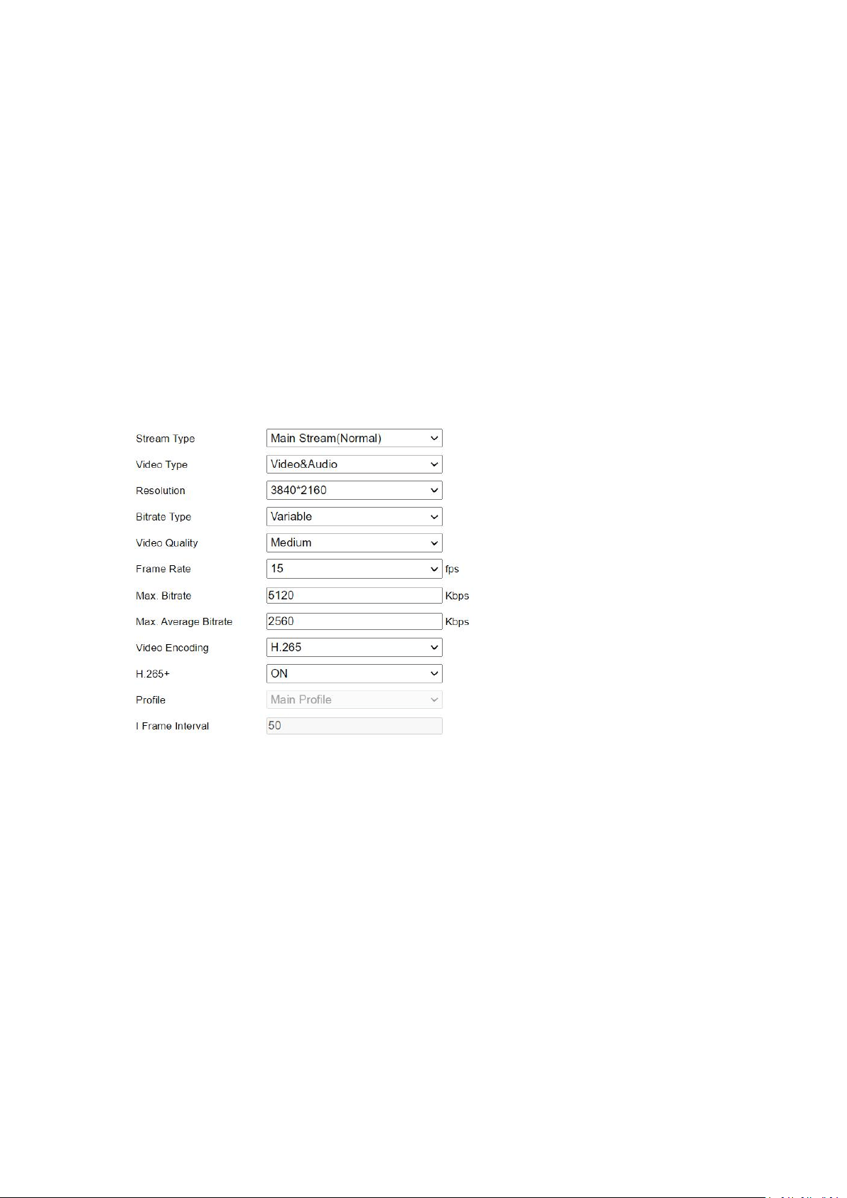
5.4 Video/Audio
Video Settings
Stream type
Main Stream:The stream stands for the best stream performance the device supports. It usually
offers the best resolution and frame rate the device can do. But high resolution and frame rate
usually means larger storage space and higher bandwidth requirements in transmission.
Sub Stream: The stream usually comparatively low resolution options, which consumes less
bandwidth and storage space.
Other Streams:Steams other than the main stream and sub stream may also be offered for
customized usage.
Video Type: Select the stream type to video stream, or video & audio composite stream. The
audio signal will be recorded only when the Video Type is Video & Audio.
Resolution: Select the resolution of the video output. Select video resolution according to actual
needs. Higher resolution requires higher bandwidth and storage.
Bit rate Type: Select the bit rate type to constant or variable.
Constant Bit rate: It means that the stream is compressed and transmitted at a comparatively
fixes bit rate. The compression speed is fast, but mosaic may occur on the image.
Variable Bit rate: It means that the device automatically adjust the bit rate under the set Max.
Bit rate. The compression speed is slower than that of the constant bit rate. But it guarantees
the image quality of complex scenes.
Video Quality: When bit rate type is selected as Variable, 6 levels of video quality are
selectable.Select a video quality according to actual needs. Note that higher video quality
requires higher bandwidth.
Frame Rate: Set the frame rate. The frame rate is to describe the frequency at which the video
stream is updated and it is measured by frames per second (fps). A higher frame rate is
advantageous when there is movement in the video stream. Note that higher frame rate requires
higher bandwidth and larger storage space.
Max. Bitrate: Set the maximum bitrate to 32 to 16384 Kbps. The higher value corresponds to the
higher video quality, but the higher bandwidth is required.
Note: The limit of the maximum bitrate value varies according to different camera platforms. For
some certain cameras, the maximum limit is 8192 Kbps or 12288 Kbps.

30
Video Encoding: The camera supports multiple video encoding types, such as H.264, H.265,
MJPEG, and MPEG4. Supported encoding type for different stream types may differ. H.265 is a
new encoding technology. Compared with H.264, it reduces the transmission bit rate under the
same resolution, frame rate and image quality.
Note: Selectable video encoding types may vary according to different camera models.
H.264+ and H.265+:
H.264+: If you set the main stream as the stream type, and H.264 as the video encoding, you
can see H.264+ available. H.264+ is an improved compression coding technology based on
H.264. By enabling H.264+, users can estimate the HDD consumption by its maximum
average bitrate. Compared to H.264, H.264+ reduces storage by up to 50% with the same
maximum bitrate in most scenes.
H.265+: If you set the main stream as the stream type, and H.265 as the video encoding, you
can see H.265+ available. H.265+ is an improved compression coding technology based on
H.265. By enabling H.265+, users can estimate the HDD consumption by its maximum
average bitrate. Compared to H.265, H.265+ reduces storage by up to 50% with the same
maximum bitrate in most scenes.
You need to reboot the camera if you want to turn on or turn off the H.264+/H.265+. If you
switch from H.264+ to H.265+ directly, and vice versa, a reboot is not required by the system.
Notes:
Upgrade your video player to the latest version if live view or playback does not work
properly due to compatibility.
With H.264+/H.265+ enabled, the parameters such as profile, I frame interval, video quality,
and SVC are greyed out.
With H.264+/H.265+ enabled, some functions are not supported. For those functions,
corresponding interfaces will be hidden.
H.264+/H.265+ can spontaneously adjust the bitrate distribution according the
requirements of the actual scene in order to realize the set maximum average bitrate in the
long term. The camera needs at least 24 hours to adapt to a fixed monitoring scene.
Max. Bitrate: When you set a maximum bitrate, its corresponding recommended maximum
average bitrate will be shown in the Max. Average Bitrate box. You can also set the maximum
average bitrate manually from 32 Kbps to the value of the set maximum bitrate.
Profile: Basic profile, Main Profile and High Profile for coding are selectable.This function
means that under the same bitrate, the more complex the profile is, the higher the quality of the
image is, and the requirement for network bandwidth is also higher.
I Frame Interval: Set the I-Frame interval from 1 to 400. I-frame interval defines the number of
frames between 2 I-frames. In H.264 and H.265, an I-frame, or intra frame, is a self-contained
frame that can be independently decoded without any reference to other images. An I-frame
consumes more bits than other frames. Thus, video with more I-frames, in other words, smaller
I-frame interval, generates more steady and reliable data bits while requiring more storage
space.
31
SVC: Scalable Video Coding (SVC) is the name for the Annex G extension of the H.264 or H.265
video compression standard. The objective of the SVC standardization has been to enable the
encoding of a high-quality video bitstream that contains one or more subset bitstreams that can
themselves be decoded with a complexity and reconstruction quality similar to that achieved
using the exiting H.264 or H.265 design with the same quantity of data as in the subset bitstream.
The subset bitstream is derived by dropping packets from the larger bitstream.
SVC enables forward compatibility for older hardware: the same bitstream can be consumed by
basic hardware which can only decode a low resolution subset, while more advanced hardware
will be able decode high quality video stream.
Smoothing: It refers to the smoothness of the stream. The higher value of the smoothing, the
better fluency of the stream, though, the video quality may not be so satisfied. The lower value
of the smoothing is, the better quality of the stream would be, though it may appear not fluently.
Note: The video settings vary according to different camera models.
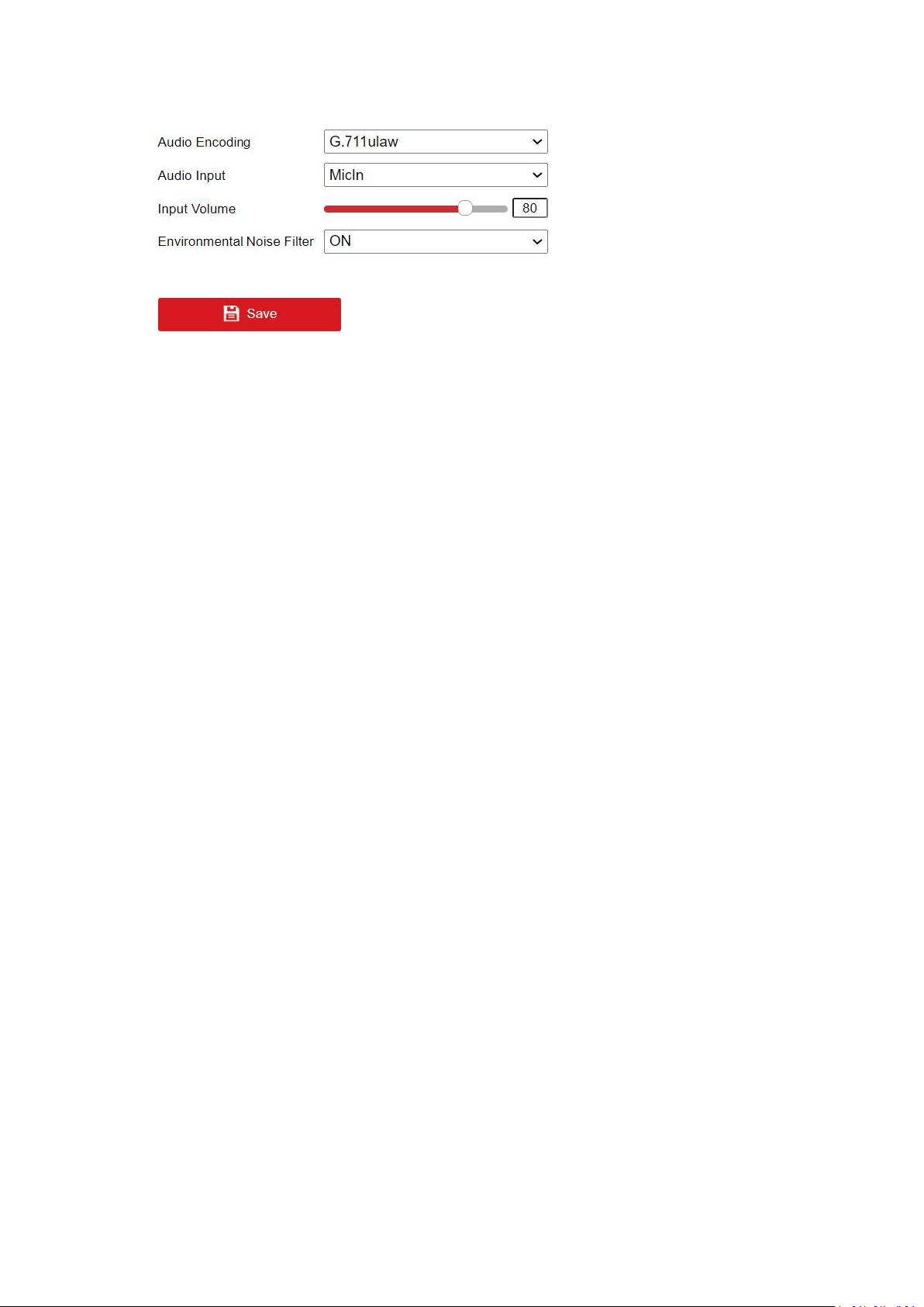
Audio
1. Enter the Audio Settings interface.
2. Configure the following settings.
Audio Encoding: G.722.1, G.711 ulaw, G.711alaw, G.726, MP2L2, AAC, PCM and MP3 are
selectable. For MP2L2 and AAC, the sampling rate and audio stream bitrate are configurable; for
PCM, the sampling rate can be set.
Audio Input: MicIn.
Input Volume: 0-100.
Environmental Noise Filter: Set it as OFF or ON. When the function is enabled, the noise in the
environment can be filtered to some extent.
Note: Audio settings vary according to different camera models.
3. Click Save to save the settings.
32
ROI Settings
Purpose:
ROI (Region of Interest) encoding helps to discriminate the ROI and background information in
video compression, which means, the technology assigns more encoding resource to the region
of interest, thus to increase the quality of the ROI whereas the background information is less
focused.
Note: ROI function varies according to different camera models.
Steps:
1. Enter the ROI settings interface.
2. Select the stream type for this channel. Five streams are selectable.
3. Set fixed regions for ROI.
1.Select the Region No. from the drop-down list.
2.Check the Enable checkbox to enable ROI function for the chosen region.
3.Click Drawing. Click and drag the mouse on the view screen to draw a red rectangle as
the ROI region. You can click Clear to cancel former drawing. Click Stop Drawing when you finish.
4.Select the ROI level.
5.Enter a region name for the chosen region.
6.Click Save the save the settings of ROI settings for chosen fixed region.
7.Repeat steps i) to vi) to setup other fixed regions.
4. Set dynamic region for ROI.
1.Check the checkbox to enable face tracking.
2.Select the ROI level.
5. Click Save to save all the settings.
Note: ROI level means the image quality enhancing level. The larger the value is, the better the
image quality would be.
Display Info. on Stream
Check the checkbox of Enable Dual-VCA, and the information of the objects (e.g., human, vehicle,
etc.) will be marked in the video stream. And then you can set rules on the connected rear-end
device to detect the events including line crossing, intrusion, etc.
Target Cropping
Purpose:
33
You can specify a target area on the live video, and then the specified video area can be
displayed via the third stream in some certain resolution, thus to provide more details of the
target area if needed.
Note: Target cropping function varies according to different camera models.
Steps:
1. Enter the Target Cropping settings interface.
2. Check Enable Target Cropping checkbox to enable the function.
3. Set Third Stream as the stream type.
4. Select the cropping resolution for the video display of target area. A red rectangle is
displayed on the live video to mark the target area, and you can click-and-drag the rectangle
to locate the target area as desired.
5. Click Save to save the settings.
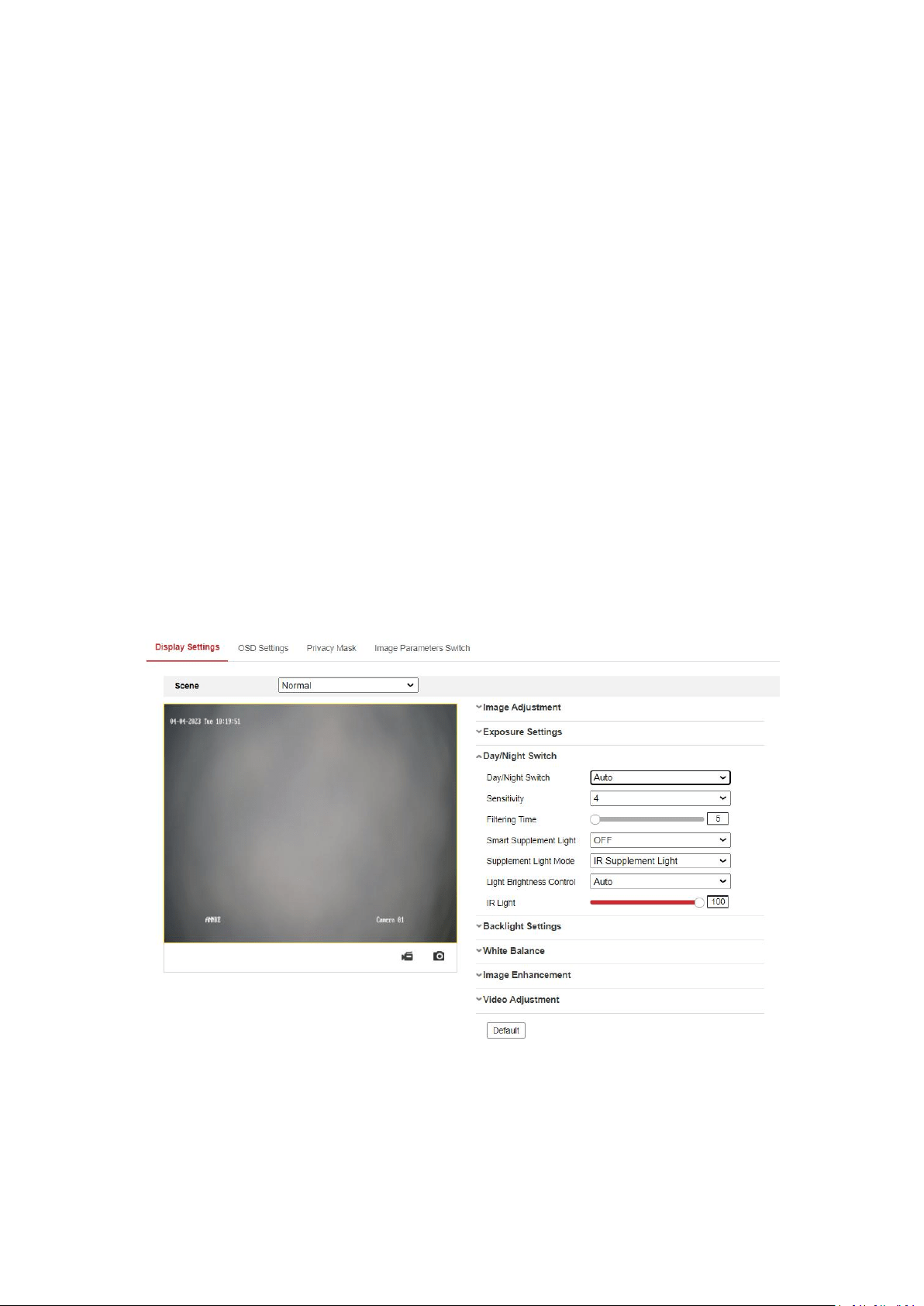
5.5 Image
Display Settings
Scene Mode: There are several sets of image parameters predefined for different installation
environments.Select a scene according to the actual installation environment to speed up the
display settings. Include Normal, Back light,Front light, Low Illumination, and custom setting.
Note: The display settings vary according to different models.
Image Adjustment
Brightness describes bright of the image, which ranges from 1 to 100, and the default value is 50.
Contrast describes the contrast of the image, which ranges from 1 to 100, and the default value
is 50.
34
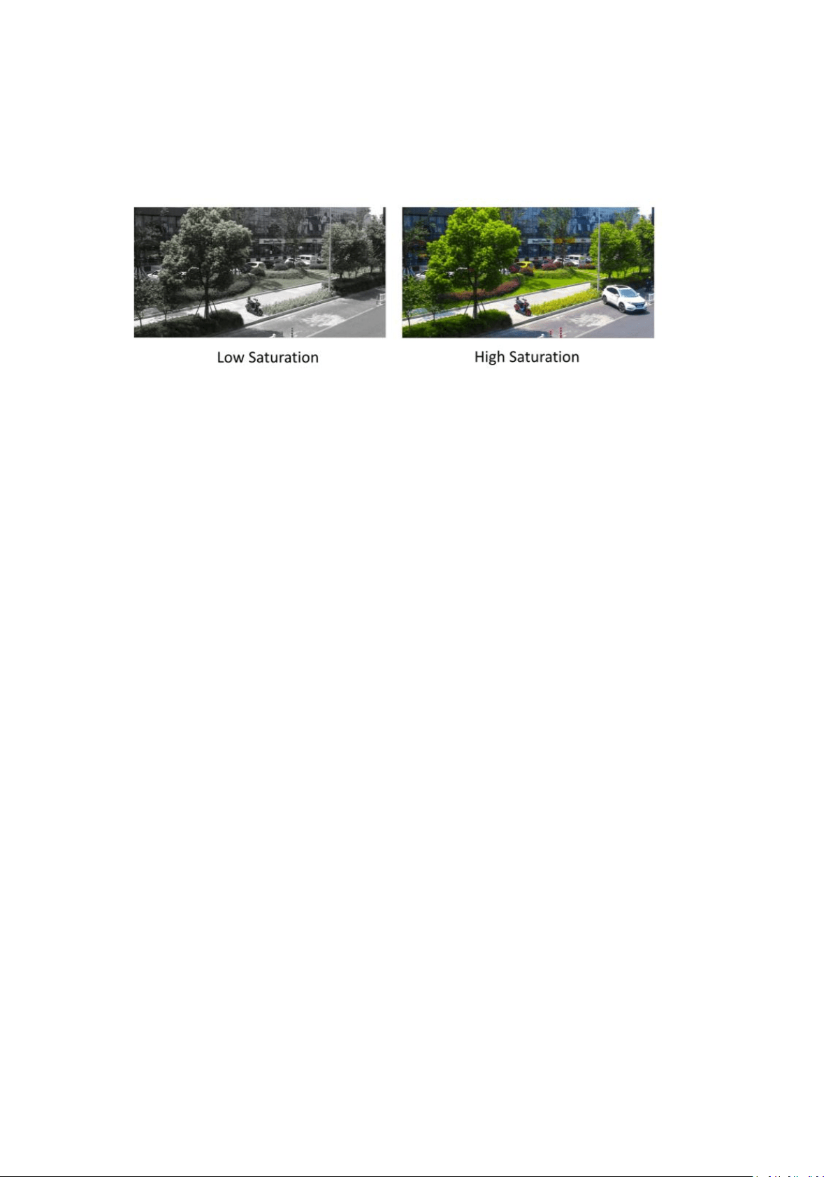
Saturation describes the colorfulness of the image color, which ranges from 1 to 100, and the
default value is 50.
Sharpness describes the edge contrast of the image, which ranges from 1 to 100, and the default
value is 50.
Exposure Settings
Only the fixed mode is available.
The exposure time refers to the electronic shutter time, which ranges from 1/3 to 1/100,000 s.
Adjust it according to the actual luminance condition.
Day/Night Switch
Day/night switch here is realized by control of IR cut-off filter. Select the day/night switch mode
from the drop-down list.
Note: The day/night switch function varies according to different models.
Day: the camera stays at day mode.
Night: the camera stays at night mode.The image is black/white or colorful and the supplement
light will be enabled to ensure clear live view image at night.
Note: Only certain device models support the supplement light and colorful image.
Auto: the camera switches between the day mode and the night mode according to the
illumination automatically. The sensitivity ranges from 0 to 7, the higher the value is, the easier
the mode switches. The filtering time refers to the time interval between the day/night switch.
You can set it from 5s to 120s.
Scheduled-Switch: Set the start time and the end time to define the duration for day/night
mode.
Triggered by Alarm Input: The switch is triggered by alarm input, and you can set the triggering
status to day or night.
Smart Supplement Light gives user an option to turn ON/OFF the supplement light.
Light Brightness Control: Auto and Manual are selectable. Select AUTO, and the supplement light
changes according to the actual luminance. E.g., if the current scene is bright enough, then the
supplement light adjusts itself to lower power; and if the scene is not bright enough, the light
adjusts itself to higher power.Select Manual, and you can adjust the supplement by adjusting the
distance. E.g., If the object is near the camera, the device adjusts the supplement light to lower
power, and the light is in higher power if the object is far away.
Supplement Light Mode: Cameras with different functions have different fill light modes.
35
IR Supplement Mode: The IR light is always on, and video imaging remains black and white (at
night).
White Light Supplement Mode: White light is always on, and the camera captures color imaging
24/7.
Smart Mode: In this mode, when there is no target in the area, the camera uses only the IR light,
which is invisible to the human eye and eco-friendly. When a target appears, the camera
automatically triggers the white light, resulting in vivid color imaging with clear detail. In Smart
Mode, you can benefit from overall security and adequate agility.
OFF: Turn off the fill light, relying only on the sensor's light sensitivity, the image effect will be
poor after turning off, so it is not recommended to turn it off.
Backlight Settings
BLC: If you focus on an object against strong backlight, the object will be too dark to be seen
clearly. BLC compensates light to the object in the front to make it clear. OFF, Up, Down, Left,
Right, Center, Auto and Custom are selectable.
Note: If BLC mode is set as Custom, you can draw an red rectangle on the live view image as the
BLC area.
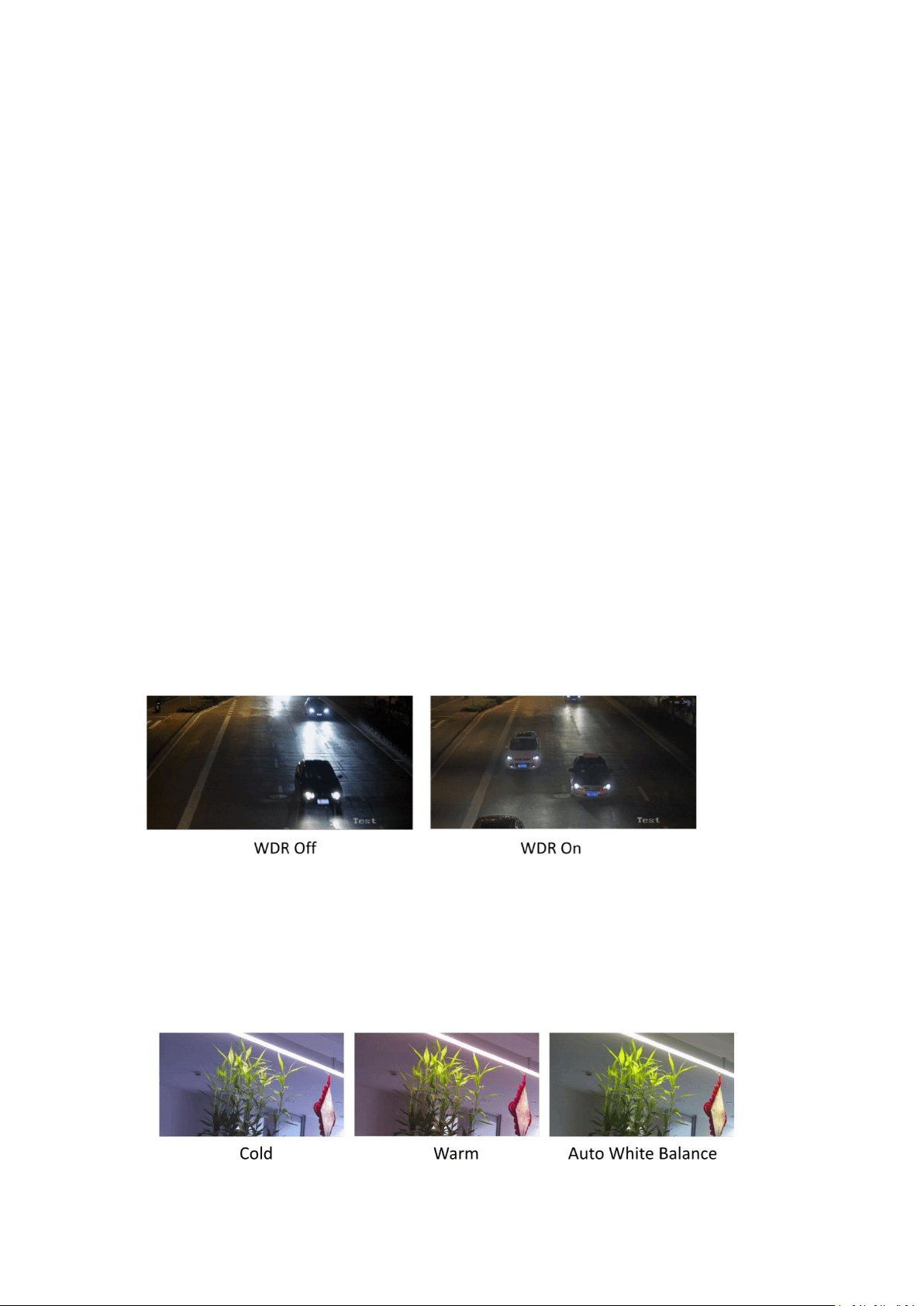
WDR: Wide Dynamic Range can be used when there is a high contrast of the bright area and the
dark area of the scene. You can adjust wide dynamic level from 0 to 100. When there are both
very bright and very dark areas simultaneously in the field of view, you can enable the WDR
function and set the level. WDR automatically balances the brightness level of the whole image
and provides clear images with more details.
Note:When WDR is enabled, some other functions may be not supported.
HLC: When the bright area of the image is over-exposed and the dark area is under-exposed, the
HLC (High Light Compression)function can be enabled to weaken the bright area and brighten the
dark area, so as to achieve the light balance of the overall picture.
White Balance
White balance is the white rendition function of the camera used to adjust the color
temperature according to the environment.
Image Enhancement
36
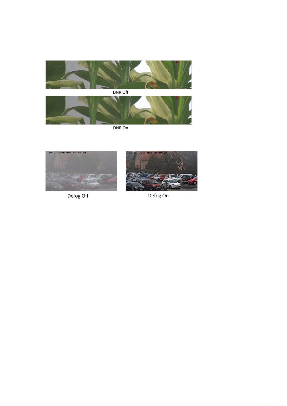
Digital Noise Reduction: DNR reduces the noise in the video stream. OFF, Normal Mode and
Expert Mode are selectable. Set the DNR level from 0 to 100, and the default value is 50 in
normal mode. In expert mode, you can adjust space DNR level and time DNR level separately.
Defog Mode: You can enable the defog function when the environment is foggy and the image is
misty. It enhances the subtle details so that the image appears clearer.
Electrical Image Stabilizer: EIS reduces the effects of vibration in a video. Increase the stability of
video image by using jitter compensation technology.
Grey Scale: You can choose the range of the grey scale as [0-255] or [16-235].
Note: Defog, Electrical Image Stabilizer and Grey Scale are only supported by certain camera
models.
Video Adjustment
Mirror: It mirrors the image so you can see it inverse. Left/Right, Up/Down, Center, and OFF are
selectable.
Rotate: To make a complete use of the 16:9 aspect ratio, you can enable the rotate function
when you use the camera in a narrow view scene.
When installing, turn the camera to the 90 degrees or rotate the 3-axis lens to 90 degrees, and
set the rotate mode as on, you will get a normal view of the scene with 9:16 aspect ratio to
ignore the needless information such as the wall, and get more meaningful information of the
scene.
Scene Mode: Choose the scene as indoor or outdoor according to the real environment.
Video Standard: 50 Hz and 60 Hz are selectable. Choose according to the different video
standards; normally 50 Hz for PAL standard and 60 Hz for NTSC standard.
Lens Distortion Correction: Select ON/OFF to enable/disable the lens distortion correction. The
distorted image caused by the wide-angle lens can be corrected if this function enabled.

37
Note: The video adjustment settings vary according to different models.
OSD Settings
OSD (On-screen Display) refers to the camera name, time/date, customized information
displayed on the live view.
Note: This function varies according to different camera models.
Steps:
1. Enter the OSD Settings interface.
2. Check the corresponding checkbox to select the display of camera name, date or week if
required.
3. Edit the camera name in the text field of Camera Name.
4. Select from the drop-down list to set the time format, date format, display mode, OSD size,
font color and alignment.
5. Click Save to activate above settings.
Privacy Mask
Privacy Mask enables you to cover certain areas on the live video to prevent certain spots in the
surveillance area from being live viewed and recorded.
Steps:
1. Enter the Privacy Mask Settings interface.
2. Check the checkbox of Enable Privacy Mask to enable this function.
3. Click Draw Area.
4. Click and drag the mouse in the live video window to draw the mask area.
5. Click Stop Drawing to finish drawing or click Clear All to clear all of the areas you set without
saving them.
6. Click Save to save the settings.
Picture Overlay
Note: The function is only supported by certain camera models.
Picture overlay enables you to overlay a picture on the image. This function enables a certain
enterprise or users to overlay their logo on the image.
Steps:
1. Enter the Picture Overlay Settings interface.
2. Click Browse to select a picture.
3. Click Upload to upload it.
4. Check Enable Picture Overlay checkbox to enable the function.
5. Click and drag the picture to adjust its position.
6. Click Save to save the settings.
Note: The picture must be in RGB24 bmp format and the maximum size of the picture is
128*128.
Image Parameters Switch
Note: The function is only supported by certain camera models.
Purpose:

38
Switch the image parameters to the scene automatically in certain time periods.
Steps:
1. Check Enable to enable the function.
2. Select and configure the corresponding time period and the scene.
3. Click Save to activate above settings.
5.6 Event
5.6.1 Motion Detection
Note:
The function is only supported by certain camera models.
Purpose:
It detects the moving objects in the configured surveillance area, and triggers the certain action
as a respond to detection. In order to detect the moving objects accurately and reduce the false
alarm rate, normal configuration and expert configuration are selectable for different motion
detection environment.
Normal Configuration
Normal configuration adopts one set of parameters for motion detection during the day and at
night.
Task 1: Set the Motion Detection Area.
Steps:
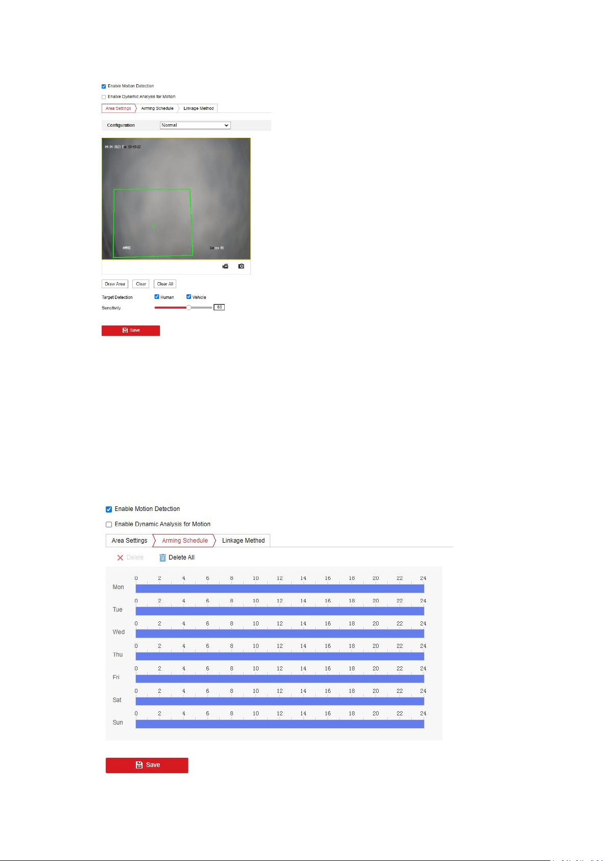
1. Check the checkbox of Enable Motion Detection.
2. Check the checkbox of Enable Dynamic Analysis for Motion, and then the detected motion
objects are marked with green irregular rectangles on the live video.
Note: To mark the motion objects on the live video, go to Local Configuration> Live View
Parameters and enable the Rules.
3. Go to Area Settings and click to draw a motion detection area.
4. (Optional) Click Clear All to clear all of the areas.
5. (Optional) Select detection target. Human and vehicle are available.
6. (Optional) Move the slider to set the sensitivity of the detection.
39
Task 2: Set the Arming Schedule for Motion Detection.
Steps:
1. Click Arming Schedule to enter the arming schedule interface.
2. Click on the time bar and drag the mouse to select the time period.Click delete or delete all
to delete the configured schedule.
3. Move the mouse to the end of each day, a copy dialogue box pops up, and you can copy the
current settings to other days.
4. Click Save to save the settings.
Note: The time of each period can’t overlap. Up to 8 periods can be configured for each day.
40
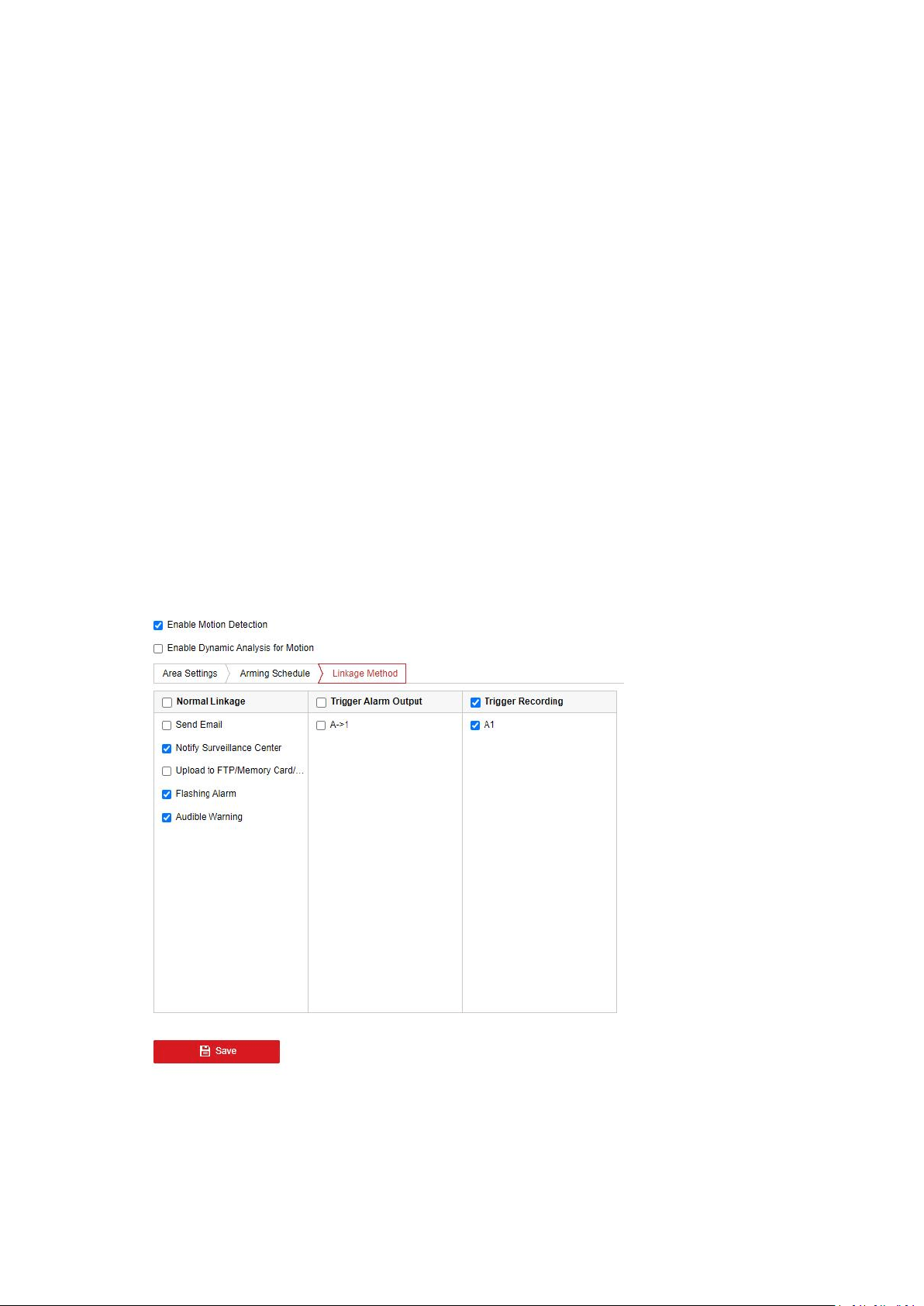
Task 3: Set the Linkage Method for Motion Detection.
Click Linkage Method and check the checkbox to select the linkage method. Notify surveillance
center, send email, upload to FTP/Memory Card/NAS, trigger recording and trigger alarm output
are selectable. You can specify the linkage method when an event occurs.
Note: Linkage method may vary according to different models.
Notify Surveillance Center: Send an exception or alarm signal to remote management software
when an event occurs.
Send Email: Send an email with alarm information to a user or users when an event occurs.
Upload to FTP/Memory Card/NAS: Capture the image when an alarm is triggered and upload
the picture to a FTP server, local memory card, or network attached storage (NAS).
Notes:
1. Go to Configuration > Storage > Schedule Settings > Capture > Capture Parameters page,
enable the event-triggered snapshot, and set the capture interval and capture number.
2. The captured image can also be uploaded to the memory card or network disk if available.
Trigger Recording:The video will be recorded when the motion is detected. You have to set the
recording schedule first.
Trigger Alarm Output: Trigger one or more external alarm outputs when an event occurs.
Note: Go to Configuration > Event > Basic Event > Alarm Output > Alarm Schedule page, set the
arming schedule of the alarm output.
Expert Configuration
Expert mode is mainly used to configure the sensitivity and proportion of object on each area for
different Scheduled Image Settings at day and night.
Scheduled Image Settings: OFF

41
Steps:
1. Draw the detection area as in the normal configuration mode. The supported area varies
according to the different camera models.
2. Select OFF for Scheduled Image Settings.
3. Select the area by clicking the area No.
4. Slide the cursor to adjust the sensitivity and proportion of object on the area for the
selected area.
5. Set the arming schedule and linkage method as in the normal configuration mode.
6. Click Save to save the settings.
Scheduled Image Settings: Auto-Switch
Steps:
1. Draw the detection area as in the normal configuration mode. The supported area varies
according to the different camera models.
2. Select Auto-Switch for Scheduled Image Settings.
3. Select the area by clicking the area No.
4. Slide the cursor to adjust the sensitivity and proportion of object on the area for the
selected area in the daytime.
5. Slide the cursor to adjust the sensitivity and proportion of object on the area for the
selected area at night.
6. Set the arming schedule and linkage method as in the normal configuration mode.
7. Click Save to save the settings.
Scheduled Image Settings: Scheduled-Switch
Steps:
1. Draw the detection area as in the normal configuration mode. The supported area varies
according to the different camera models.
2. Select Scheduled-Switch for Scheduled Image Settings.
3. Select the start time and the end time for the switch timing.
4. Select the area by clicking the area No.
5. Slide the cursor to adjust the sensitivity and proportion of object on the area for the
selected area in the daytime.
6. Slide the cursor to adjust the sensitivity and proportion of object on the area for the
selected area at night.
7. Set the arming schedule and linkage method as in the normal configuration mode.
8. Click Save to save the settings.
5.6.2 Video Tampering
Purpose:
It detects if the lens is covered and take response actions when the alarm is triggered.
Note:
The function is only supported by certain camera models.
Steps:

42
1. Enter the video tampering Settings interface.
2. Check the Enable checkbox to enable the video tampering detection.
3. Go to Area Settings and click Draw Area to draw a detection area.
4. Click Stop Drawing to finish area drawing.
5. (Optional) Click Clear All to clear all of the areas.
6. Move the slider to set the sensitivity.
7. Click Arming Schedule to enter the arming schedule interface.
8. Click on the time bar and drag the mouse to select the time period.Click delete or delete
all to delete the configured schedule.
9. Move the mouse to the end of each day, a copy dialogue box pops up, and you can copy
the current settings to other days.
10. Click Save to save the settings.
11. Go to Linkage Method and check the checkbox to select the linkage method.
12. Click Save to save the settings.
5.6.3 Alarm Input
Note:
The function is only supported by certain camera models.
Purpose:
It detects the alarm input and take response actions when the alarm is triggered.
Steps:
1. Enter the Alarm Input Settings interface.
2. Choose the alarm input No. and the Alarm Type. The alarm type can be NO (Normally
Open) and NC (Normally Closed). Edit the name to set a name for the alarm input
(optional).
3. Click Arming Schedule to set the arming schedule for the alarm input.
4. Click Linkage Method and check the checkbox to select the linkage methods.
5. You can copy your settings to other alarm inputs.
6. Click Save to save the settings.
5.6.4 Alarm Output
Purpose:
It detects the alarm output and take response actions when the alarm is triggered.
Steps:
1. Enter the Alarm Output Settings interfaces.
2. Select one alarm output channel in the Alarm Output drop-down list. You can also set a
name for the alarm output (optional).
3. The Delay time can be set to 1s, 5s, 10s, 30s, 1min, 2min, 5min, 10min or Manual. The delay
time refers to the time duration that the alarm output remains in effect after alarm occurs.
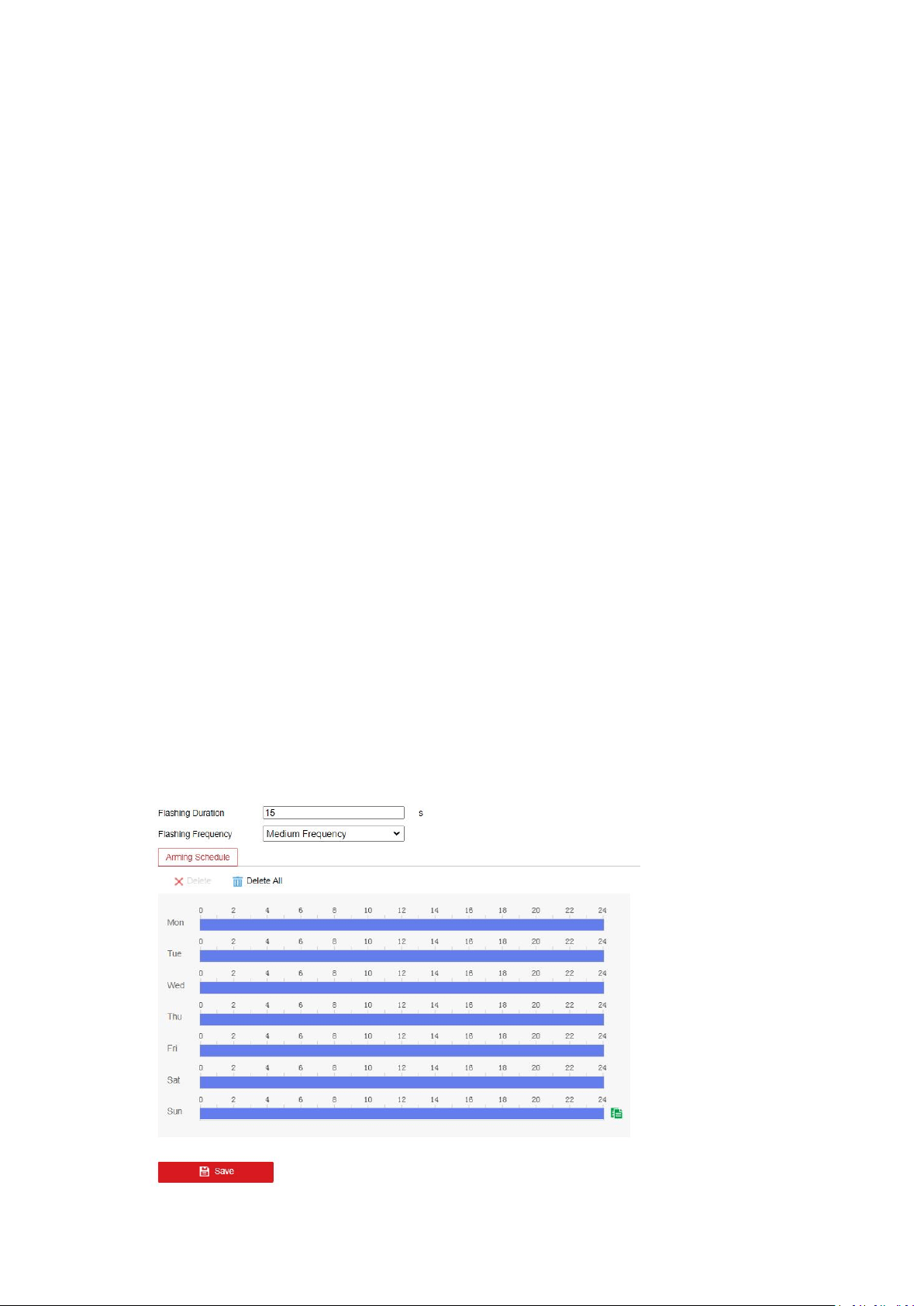
43
4. Click on the time bar and drag the mouse to select the time period.Click delete or delete all
to delete the configured schedule.
5. You can copy the settings to other alarm outputs.
6. Click Manual Alarm to trigger an alarm manually, and click Clear Alarm to cancel the alarm.
7. Click Save to save the settings.
5.6.5 Exception
Purpose:
It detects the HDD full, HDD error, network disconnected, IP address conflicted and illegal login
to the cameras.
Steps:
1. Enter the Exception Settings interface.
2. Select an exception type.
3. Check the checkbox to set the actions taken for the Exception alarm.
4. Click Save to save the settings.
5.6.7 Flashing Alarm Light Output
This page offers options to configure flashing light when the Flashing Alarm is enabled as an
linkage method.
Note: the function is only supported by certain camera models.
Flashing Duration: the time period the flashing lasts when one alarm happens.The range is 1-60.
Flashing Frequency: the flashing speed of the light. High, Medium, Low, and normally on are
selectable.
Brightness: the brightness of the light.
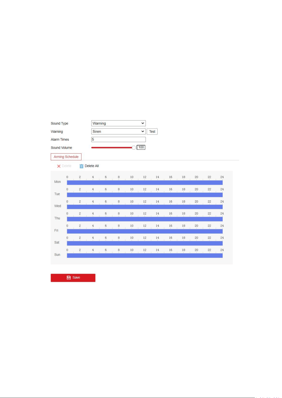
44
5.6.8 Audible Alarm Output
This page offers options to configure audible warning when the Audible Warning is enabled as an
linkage method.
Note: the function is only supported by certain camera models.
Alarm Sound Type: the content of audible warning.Warning, prompt, custom audio is selectable.
Waning: Warning connect. There are 11 audio selectable.
Alarm Times: the repeating times of the warning. The range is 1-50.
Sound volume: Adjust the volume of alarm. Move the slider to right to turn up the volume and
lift to turn down the volume.
5.6.9 Video Quality Diagnosis
When the video quality of the device is abnormal and the alarm linkage is set, the alarm will be
triggered automatically.
Steps:
1. Select the Diagnosis Type.
2. Check Enable Brightness Exception.
3. Set the corresponding parameters.

45
1.Alarm Detection Interval: Range [5 to 300].
2.Sensitivity: The higher the value is, the more easily the exception can be detected.
3.Alarm Delay Times: The device uploads the alarm when the alarm reaches the set
number of times.
4. Click Arming Schedule to set the arming schedule.
5. Click Linkage Method to select the linkage methods..
6. Click Save to save the settings.
Note:The function varies according to different models.
5.6.10 PIR Alarm
Purpose:
A PIR (Passive Infrared) alarm is triggered when an intruder moves within the detector's field of
view. The heat energy dissipated by a person, or any other warm blooded creature such as dogs,
cats, etc., can be detected.
Note:
The function is only supported by certain camera models.
Steps:
1. Check the checkbox of Enable to activate the PIR alarm function.
2. Enter the alarm name in the text field as desired.
3. Click Arming Schedule to set the arming schedule.
4. Click Linkage Method to select the linkage methods.
5. Click Save to save the settings.
5.6.11 Audio Exception Detection
Note:
The function is only supported by certain camera models.
Purpose:
Audio exception detection function detects the abnormal sounds in the surveillance scene, such
as the sudden increase / decrease of the sound intensity, and some certain actions can be taken
when the alarm is triggered.
Steps:
1. Enter the Audio Exception Detection interface.
2. Check the checkbox of Audio Loss Detection to enable the audio loss detection function.
3. Check the checkbox of Sudden Increase of Sound Intensity Detection to detect the sound
steep rise in the surveillance scene. You can set the detection sensitivity and threshold for
sound steep rise.
4. Check the checkbox of Sudden Decrease of Sound Intensity Detection to detect the sound
steep drop in the surveillance scene. You can set the detection sensitivity for sound steep
drop.
Notes:

46
1.Sensitivity: Range [1-100], the smaller the value is, the more severe the change should
be to trigger the detection.
2.Sound Intensity Threshold: Range [1 to 100], it can filter the sound in the environment,
the louder the environment sound, the higher the value should be. You can adjust it
according to the real environment.
5. You can view the real-time volume of the sound.
6. Click Arming Schedule to set the arming schedule.
7. Click Linkage Method and select the linkage methods.
8. Click Save to save the settings.
5.6.12 Defocus Detection
Note:
The function is only supported by certain camera models.
Purpose:
The image blur caused by defocus of the lens can be detected, and some certain actions can be
taken when the alarm is triggered.
Steps:
1. Enter the Defocus Detection settings interface.
2. Check the checkbox of Enable to enable the function.
3. Click-and-drag the slider to set the detection sensitivity. The sensitivity value ranges from 1
to 100, and the higher the value is, the more easily the defocus image can trigger the alarm.
4. Select the linkage methods. You can select the linkage methods:send email, notify
surveillance center,trigger alarm output. For cameras that support ABF, you can also select
Focus to link.
Note: Only certain camera models support the linkage method Focus.
5. Click Save to save the settings.
5.6.13 Scene Change Detection
Note:
The function is only supported by certain camera models.
Purpose:
Scene change detection function detects the change of surveillance environment affected by the
external factors; such as the intentional rotation of the camera, and some certain actions can be
taken when the alarm is triggered.
Steps:
1. Enter the Scene Change Detection settings interface.
2. Check the Enable checkbox to enable the function.

47
3. Click-and-drag the slider to set the detection sensitivity. The sensitivity value ranges from 1
to 100, and the higher the value is, the more easily the change of scene can trigger the
alarm.
4. Click Arming Schedule to set the arming schedule.
5. Click Linkage Method to select the linkage methods.
6. Click Save to save the settings.
5.6.14 Face Detection
Note:
The function is only supported by certain camera models.
Purpose:
Face detection function detects the face appears in the surveillance scene, and some certain
actions can be taken when the alarm is triggered.
Steps:
1. Enter the Face Detection settings interface.
2. Check the Enable Face Detection checkbox to enable the function.
3. Check the checkbox of Enable Dynamic Analysis for Face Detection, and then the detected
face is marked with green rectangle on the live video.
Note: To mark the detected face on the live video, go to Configuration> Local and enable the
Rules.
4. Click-and-drag the slider to set the detection sensitivity.
Sensitivity: Range [1-5]. The higher the value is, the more easily the face can be detected.
5. Click Arming Schedule to set the arming schedule.
6. Click Linkage Method to select the linkage methods for face detection.
7. Click Save to save the settings.
5.6.15 Line Crossing Detection
Note:
The function is only supported by certain camera models.
Purpose:
Line crossing detection function detects people, vehicle or other objects which cross a
pre-defined virtual line, and some certain actions can be taken when the alarm is triggered.
Steps:
1. Enter the Line Crossing Detection settings interface.
2. Check the Enable checkbox of Line Crossing Detection to enable the function.
3. Select the line from the drop-down list for detection settings.
4. Set up the rules for the selected line.
1
.
Click the Draw Area button,and a virtual line is displayed on the live image.
2
.
Drag the line, and you can locate it on the live video as desired. Click on the line, two red

48
squares are displayed on each end, and you can drag each squares to define the shape and
length of the line.
3.Set the Max. Size and Min. Size for valid targets. Targets smaller or larger than the valid
target size are not able to trigger detection.
Max.Size: The maximum size of a valid target. Targets with larger sizes would not trigger
detection.
Min.Size: The minimum size of a valid target. Targets with smaller sizes would not
trigger detection.
4.Select the detection target. Human and vehicle are available. If the detection target is
not selected, all the detected targets will be reported, including the human and vehicle.
5.Select the direction for line crossing detection. For example, A->B means only object
crossing the line from A side to B side can be detected.
6.Drag the slider to set sensitivity value.
Sensitivity: It stands for the percentage of the body part of an acceptable target that
goes across the pre-defined line.Sensitivity = 100 - S
1
/S
T
*100
S
1
stands for the target body part that goes across the pre-defined line. S
T
stands for the
complete target body.
Example: if you set the value as 60, the action can be counted as a line crossing action
only when 40 percent body part goes across the line.
7.Select the target validity.
Target Validity: The lower the validity is, the more easily the alarm would be triggered.
5. Repeat the above steps to configure other lines. Up to 4 lines can be set. You can click the
Clear button to clear all pre-defined lines.
6. Click Arming Schedule to set the arming schedule.
7. Click Linkage Method and select the linkage methods.Choose linkage actions when alarm
happens. Notify Surveillance Center, Send Email, Upload to FTP/Memory Card/NAS, Trigger
Channel, trigger the Alarm Output, Flashing Alarm or Audible Warning are available
generally.
Note: Trigger channel, trigger alarm output, flashing Alarm and audible warning are only
supported by certain camera models.
8. Click Save to save the settings.
5.6.16 Intrusion Detection
Note:
The function is only supported by certain camera models.
Purpose:
Intrusion detection function detects people, vehicle or other objects which enter and loiter in a
pre-defined virtual region, and some certain linked actions can be taken when the alarm is
triggered.
Steps:
1. Enter the Intrusion Detection settings interface.
2. Check the Enable checkbox to enable the function.

49
3. Select a region number from the drop-down list of Region.
4. Set up the pre-defined region for the selected region number.
Region: A pre-defined vertexes area on the live view image. Targets, such as, people, vehicle
or other objects, who enter and loiter in the region will be detected and trigger the set alarm.
1.Click Draw Area to start drawing.
2.Click on the live video to specify the four vertexes of the detection region, and right click
to complete drawing.
3.Set the Max. Size and Min. Size for valid targets. Targets smaller or larger than the valid
target size are not able to trigger detection.
Max.Size: The maximum size of a valid target. Targets with larger sizes would not trigger
detection.
Min.Size: The minimum size of a valid target. Targets with smaller sizes would not trigger
detection.
4.Select the detection target. Human and vehicle are available. If the detection target is
not selected, all the detected targets will be reported, including the human and vehicle.
5.Set the time threshold, detection sensitivity and target validity for intrusion detection.
Threshold: Range [0-10]s. The threshold for the time of the object loitering in the region. If
you set the value as 0, alarm is triggered immediately after the object entering the region.
Sensitivity: Range [1-100]. Sensitivity stands for the percentage of the body part of an
acceptable target that enters the pre-defined region.
Sensitivity = 100 - S
1
/S
T
*100
S
1
stands for the target body part that enters the pre-defined region. S
T
stands for the
complete target body.
Example: if you set the value as 60, the action can be counted as an intrusion only when
40 percent body part enters the region.
target Validity: The lower the validity is, the more easily the alarm would be triggered.
5. Repeat the above steps to configure other regions. Up to 4 regions can be set. You can click
the Clear button to clear all pre-defined regions.
6. Click Arming Schedule to set the arming schedule. Choose linkage actions when alarm
happens. Notify Surveillance Center, Send Email, Upload to FTP, Trigger Channel or trigger
the Alarm Output are available generally.
7. Click Linkage Method and select the linkage methods. Choose linkage actions when alarm
happens. Notify Surveillance Center, Send Email, Upload to FTP/Memory Card/NAS, Trigger
Channel, trigger the Alarm Output, Flashing Alarm or Audible Warning are available
generally.
Note: Trigger channel, trigger alarm output, flashing Alarm and audible warning are only
supported by certain camera models.
8. Click Save to save the settings.
5.6.17 Region Entrance Detection
Note:

50
The function is only supported by certain camera models.
Purpose:
Region entrance detection function detects people, vehicle or other objects which enter a
pre-defined virtual region from the outside place, and some certain actions can be taken when
the alarm is triggered.
Steps:
1. Enter the Region Entrance Detection settings interface.
2. Check the Enable checkbox to enable the function.
3. Select the Region from the drop-down list for detection settings.
4. Set up rules for the selected region.
1.Click Draw Area to start drawing.
2.Click on the live video to specify the four vertexes of the detection region, and right click
to complete drawing.
3.Set the Max. Size and Min. Size for valid targets. Targets smaller or larger than the valid
target size are not able to trigger detection.
Max.Size: The maximum size of a valid target. Targets with larger sizes would not trigger
detection.
Min.Size: The minimum size of a valid target. Targets with smaller sizes would not trigger
detection.
4.Select the detection target. Human and vehicle are available. If the detection target is
not selected, all the detected targets will be reported, including the human and vehicle.
5.Set sensitivity for region entrance detection.
Sensitivity: Range [1-100]. Sensitivity stands for the percentage of the body part of an
acceptable target that enters the pre-defined region.
Sensitivity = 100 - S
1
/S
T
*100
S
1
stands for the target body part that enters the pre-defined region. S
T
stands for the
complete target body.
Example: if you set the value as 60, the action can be counted as an region entrance
action only when 40 percent body part enters the region.
6.Select the target validity.
Target Validity: The lower the validity is, the more easily the alarm would be triggered.
5. Repeat the above steps to configure other regions. Up to 4 regions can be set. You can click
the Clear button to clear all pre-defined regions.
6. Click Arming Schedule to set the arming schedule.Choose linkage actions when alarm
happens. Notify Surveillance Center, Send Email, Upload to FTP, Trigger Channel or trigger
the Alarm Output are available generally.
7. Click Linkage Method and select the linkage methods.Choose linkage actions when alarm
happens. Notify Surveillance Center, Send Email, Upload to FTP/Memory Card/NAS, Trigger
Channel, trigger the Alarm Output, Flashing Alarm or Audible Warning are available
generally.
Note: Trigger channel, trigger alarm output, flashing Alarm and audible warning are only
supported by certain camera models.
8. Click Save to save the settings.

51
5.6.18 Region Exiting Detection
Note:
The function is only supported by certain camera models.
Purpose:
Region exiting detection function detects people, vehicle or other objects which exit from a
pre-defined virtual region, and some certain actions can be taken when the alarm is triggered.
Steps:
1. Enter the Region Exiting Detection settings interface.
2. Check Enable checkbox to enable the function.
3. Select the region from the drop-down list for detection settings.
4. Set up rules for the selected region.
1
.
Click Draw Area to start drawing.
2
.
Click on the live video to specify the four vertexes of the detection region, and right click
to complete drawing.
3
.
Set the Max. Size and Min. Size for valid targets. Targets smaller or larger than the valid
target size are not able to trigger detection.
Max.Size: The maximum size of a valid target. Targets with larger sizes would not trigger
detection.
Min.Size: The minimum size of a valid target. Targets with smaller sizes would not trigger
detection.
4
.
Select the detection target. Human and vehicle are available. If the detection target is
not selected, all the detected targets will be reported, including the human and vehicle.
5
.
Set sensitivity for region exiting detection.
Sensitivity: Range [1-100]. Sensitivity stands for the percentage of the body part of an
acceptable target that exits the pre-defined region.
Sensitivity = 100 - S
1
/S
T
*100
S
1
stands for the target body part that exits the pre-defined region. S
T
stands for the
complete target body.
Example: if you set the value as 60, the action can be counted as an region exiting action
only when 40 percent body part exits the region.
6
.
Select the target validity.
Target Validity: The lower the validity is, the more easily the alarm would be triggered.
5. Repeat the above steps to configure other regions. Up to 4 regions can be set. You can click
the Clear button to clear all pre-defined regions.
6. Click Arming Schedule to set the arming schedule.
7. Click Linkage Method and select the linkage methods.Choose linkage actions when alarm
happens. Notify Surveillance Center, Send Email, Upload to FTP/Memory Card/NAS, Trigger
Channel, trigger the Alarm Output, Flashing Alarm or Audible Warning are available
generally.
Note: Trigger channel, trigger alarm output, flashing Alarm and audible warning are only
supported by certain camera models.
8. Click Save to save the settings.

52
5.6.19 Unattended Baggage Detection
Note:
The function is only supported by certain camera models.
Purpose:
Unattended baggage detection function detects the objects left over in the pre-defined region
such as the baggage, purse, dangerous materials, etc., and a series of actions can be taken when
the alarm is triggered.
Steps:
1. Enter the Unattended Baggage Detection settings interface.
2. Check Enable checkbox to enable the function.
3. Select the region from the drop-down list for detection settings.
4. Set up rules for the selected region.
1
.
Click Draw Area to start drawing.
2
.
Click on the live video to specify the four vertexes of the detection region, and right click
to complete drawing.
3
.
Set the Max. Size and Min. Size for valid targets. Targets smaller or larger than the valid
target size are not able to trigger detection.
Max.Size: The maximum size of a valid target. Targets with larger sizes would not trigger
detection.
Min.Size: The minimum size of a valid target. Targets with smaller sizes would not trigger
detection.
4
.
Click Stop Drawing when finish drawing.
5
.
Set sensitivity for unattended baggage detection.
Sensitivity: Range [1-100]. Sensitivity stands for the percentage of the body part of an
acceptable target that enters the pre-defined region.
Sensitivity = 100 - S
1
/S
T
*100
S
1
stands for the target body part that enters the pre-defined region. S
T
stands for the
complete target body.
Example: if you set the value as 60, a target is possible to be counted as an unattended
baggage only when 40 percent body part of the target enters the region.
6
.
Set the time threshold for the detection.
Threshold: The threshold for the time of the objects left over in the region. If you set the
value as 10, alarm is triggered after the object is left and stay in the region for 10s.
7
.
Select the target validity.
Target Validity: The lower the validity is, the more easily the alarm would be triggered.
5. Repeat the above steps to configure other regions. Up to 4 regions can be set. You can click
the Clear button to clear all pre-defined regions.
6. Click Arming Schedule to set the arming schedule.
7. Click Linkage Method to select the linkage methods.
8. Click Save to save the settings.

53
5.6.20 Object Removal Detection
Note:
The function is only supported by certain camera models.
Purpose:
Object removal detection function detects the objects removed from the pre-defined region,
such as the exhibits on display, and a series of actions can be taken when the alarm is triggered.
Steps:
1. Enter the Object Removal Detection settings interface.
2. Check Enable checkbox to enable the function.
3. Select the region from the drop-down list for detection settings.
4. Set up rules for the selected region.
1
.
Click Draw Area to start drawing.
2
.
Click on the live video to specify the four vertexes of the detection region, and right click
to complete drawing.
3
.
Set the Max. Size and Min. Size for valid targets. Targets smaller or larger than the valid
target size are not able to trigger detection.
Max.Size: The maximum size of a valid target. Targets with larger sizes would not trigger
detection.
Min.Size: The minimum size of a valid target. Targets with smaller sizes would not trigger
detection.
4
.
Click Stop Drawing when finish drawing.
5
.
Set sensitivity for object removal detection.
Sensitivity: Range [1-100]. Sensitivity stands for the percentage of the body part of an
acceptable target that leaves the pre-defined region.
Sensitivity = 100 - S
1
/S
T
*100
S
1
stands for the target body part that leaves the pre-defined region. S
T
stands for the
complete target body.
Example: if you set the value as 60, a target is possible to be counted as a removed object
only when 40 percent body part of the target leaves the region.
6
.
Set the time threshold for the detection.
Threshold: The threshold for the time of the objects removed in the region. If you set the
value as 10, alarm is triggered after the object leaving the region for 10s.
5. Repeat the above steps to configure other regions. Up to 4 regions can be set. You can click
the Clear button to clear all pre-defined regions.
6. Click Area Settings to set the arming schedule.
7. Click Linkage Method to select the linkage methods.
8. Click Save to save the settings.
5.7 Storage
Record Schedule
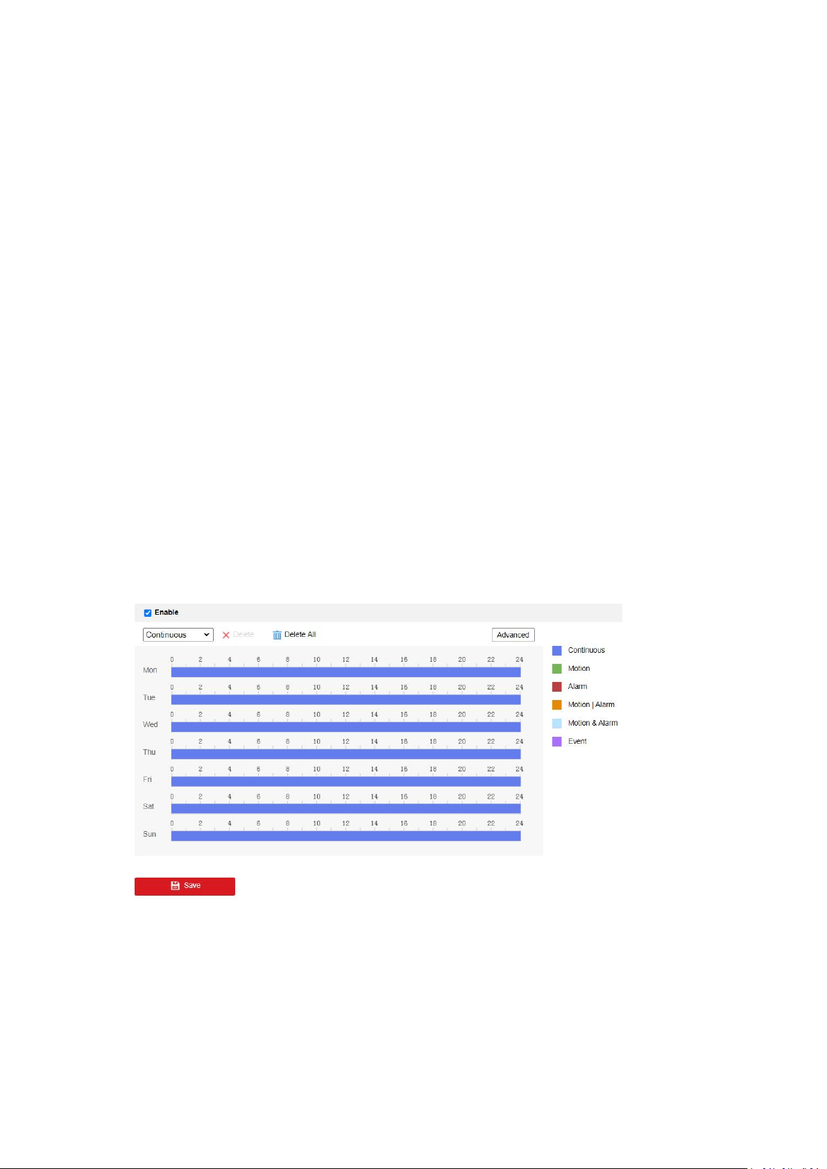
54
Note: the function varies according to different camera models.
1. Enter the Record Schedule interface.
2. Check the Enable checkbox to enable scheduled recording.
3. Click Advanced to set the camera record parameters, including overwrite, pre-record,
post-record, and ,stream type, etc.
Overwrite:Enable Overwrite to overwrite the video records when the storage space is full.
Otherwise the camera cannot record new videos.
Pre-record:The time period you set to record before the scheduled time.
Post-record: The time period you set to stop recording after the scheduled time.
Stream Type: Select the stream type for recording.
Recording Expiration: The recordings are deleted when they exceed the expired time The
expired time is configurable. Note that once the recordings are deleted, they can not be
recovered.
4. Check Enable Recording Expiration.
5. Set the expired time. The expired time should be 1 to 90 days and seven days is the default
expired time. If you enable the function in 8:00, January 2, and set the expired time to 1 day,
you can only see the recordings between 8:30, January 1 and 8:30 January 2 if you check the
recording on 8:30, January 2. The recording before 8:30, January 1 will be deleted and
cannot be recovered.
6. Select a Record Type.
7. Click-and-drag the mouse on the time bar to set the record schedule. You can copy the
record schedule to other days by clicking the green Copy icon on the right of each time bar.
8. Click Save to save the settings.
Capture Settings
Note: the function varies according to different camera models.
The captured picture can be stored in the memory card (if supported) or the network storage.
1. Enter the Capture Settings interface.
2. Go to Capture Schedule tab to configure the capture schedule by click-and-drag the mouse
on the time bar. You can copy the record schedule to other days by clicking the green Copy
icon on the right of each time bar.

55
3. Click Advanced to select stream type.
4. Click Save to save the schedule.
5. Go to Capture Parameters tab to configure the capture parameters.
6. Check Enable Timing Snapshot to enable the function. You can configure the format,
resolution, quality and interval for capture pictures.
7. Check Enable Event-Triggered Snapshot to enable the function. You can configure the format,
resolution, quality, interval and capture number for each event-triggered action.
8. Click Save to save the settings.
HDD Management
Note: the function varies according to different camera models.
HDD management allows you to view the HDD capacity, free space, status, encryption status,
type, formatting type, property and progress, etc. You can format, encrypted format or verify the
selected HDD as required. And you can assign the quota for different file types.
1. Enter the HDD settings interface.
2. Select the desired disk and operate as required.
1.The status of the disk includes Uninitialized and Normal. If the status of the disk is
Uninitialized, you can click Format to initialize the disk. When the initialization completed, the
status of disk will become Normal. Then the disk can be used normally.
2.The encryption status of the disk includes Unencrypted, Encrypted and Verification
Failed. If the status of the disk is Unencrypted, you can click Format or Encrypted Format to
format it. The encryption password is required for the encryption format. For the encrypted
memory card, its status is displayed: Encrypted or Verification Failed. If the status of the disk is
Verification Failed, you can click Parity, and enter the password for the verification. If the
verification is succeeded, its status changes to Encrypted.
3. (Optional) Define the quota for record and pictures.
1.Input the quota percentage for picture and for record.
2.Click Save and refresh the browser page to activate the settings.
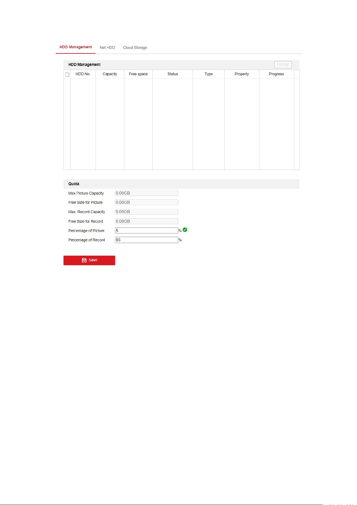
56
Net HDD
Note: the function varies according to different camera models.
The network disk should be available within the network. Configure them properly to store the
recorded files, log files, pictures, etc..
1. Enter the Net HDD settings interface.
2. Click an HDD to configure.
3. Enter the server address of the network disk, and enter the file path.
4. Select the mounting type. NFS and SMB/CIFS are selectable. And you can set the user name
and password to guarantee the security if SMB/CIFS is selected.
5. Click Test to see if the HDD is properly configured.
6. Click Save to save the settings.
Cloud Storage
It helps to upload the captured pictures and data to the cloud. The platform requests picture
directly from the cloud for picture and analysis. The function is only supported by certain models.
Notes:
1. If cloud storage is enabled, the pictures are stored in the cloud storage server preferentially.
2. Cloud storage function varies according to different camera models.
3. This function may not be supported by some camera models.
Steps:

57
1. Check the checkbox of Enable Cloud Storage.
2. Set basic parameters.
1.Protocol Version: The protocol version of the cloud storage server.
2.Server IP: The IP address of the cloud storage server. It supports IPv4 address.
3.Server Port: The port of the cloud storage server. 6001 is the default port and you are
not recommended to edit it.
4.User Name and Password: The user name and password of the cloud storage server.
5.Picture Storage Pool ID: The ID of the picture storage region in the cloud storage server.
Make sure storage pool ID and the storage region ID are the same.
3. Click Test to test the cloud storage settings.
4. Click Save to save the settings.
5.8 Face capture
Overlay and Capture
Note: Only certain camera models support the function, and the actual display may vary with
your camera model.
Display on Stream and Picture
Display VCA info. on Stream: The green frames will be displayed on the target if in a live
view or playback.
Display Target info. on Alarm Picture: There will be a frame on the target on the uploaded
alarm picture if the checkbox is checked.
Snapshot Settings
Target Picture Settings
1
.
Set the target picture size. Four types are available: Custom, Head Shot, Half-Body Shot
and Full-Body Shot. If you select the Custom, you can customized the width, head height and
body height as required.
2
.
Check Fixed Value to set the picture height.
3
.
Check Face Enhancement.
Note: Only certain camera model supports face enhancement.
Background Picture Settings
1
.
Check the Background Upload to upload the background image.
2
.
Select the Picture Quality and Resolution from the drop-down list.
Note: Background upload is only available for face capture camera.
Camera Information
Set the Device No. and Camera Info. for the camera, which can be overlaid on captured picture.
Text Overlay Information
Check desired items and adjust their order to display on captured pictures.
Draw the Shield Region
Note: Only certain camera models support the function, and the actual display may vary with
your camera model.

58
1.Click Shield Region tab to enter the shield region configuration interface
2.Click Draw Area. Draw area by left click end-points in the live view window, and right click
to finish the area drawing. Polygon area with up to 10 sides is supported.
3.Click Save to save the settings.
Note: If live view is stopped, the shield regions cannot be drawn.
Configure the Rules
Note: Only certain camera models support the function, and the actual display may vary with
your camera model.
1. Check the checkbox of Rule to enable rules of face capture.
2. Click to draw the minimum pupil distance.
3. Click to draw the maximum pupil distance.
4. Click to draw the area you want the face capture to take effect.
5. Click Save to save the settings.
6. Click Arming Schedule tab, click Edit to set the schedule time for each rule, and click Save to
save the settings.
7. Click Alarm Linkage tab, check the checkbox of corresponding linkage method for each rule,
and click Save to save the settings.
Advanced Configuration
Note: Only certain camera models support the function, and the actual display may vary with
your camera model.
Face Capture Version: It lists the current version of the VCA algorithm.
Generation Speed: The speed to identify a target. The higher the value, the fast the target will be
recognized. The default value is recommended.
Sensitivity: The sensitivity to identify a target. The higher the value is, the easier a face will be
recognized, and the higher possibility of misinformation would be. The default value of 3 is
recommended.
Face Capture Mode: Best Shot and Quick Shot are available.
Best Shot: The best shot after target leave the detection area.
Capture Times:Refers to the capture times a face will be captured during its stay in the
configured area.
Capture Threshold: It stands for the quality of face to trigger capture and alarm. Higher value
means better quality should be met to trigger capture and alarm.
Quick Shot: You can define quick shot threshold and max. capture interval.
Quick Shot Threshold: It stands for the quality of face to trigger quick shot.
Max. Capture Interval: It describes the max. time occupation for one quick shot.
Capture Times:Refers to the capture times a face will be captured during its stay in the
configured area.

59
Face Exposure: Check the checkbox to enable the face exposure. The device automatically adjusts
exposure level when human faces appear in the scene.
Reference Brightness: The reference brightness of a face in the face exposure mode. If a face
in the actual scene is brighter than the set reference brightness, the device lower the
exposure level. If a face in the actual scene is darker than the set reference, the device
increases the exposure level.
Minimum Duration: The extra time the device keeps the face exposure level after the face
disappears in the scene.
Face Filtering Time: It means the time interval between the camera detecting a face and taking a
capture action. If the detected face stays in the scene for less than the set filtering time, capture
will not be triggered. For example, if the face filtering time is set as 5 seconds, the camera will
capture the detected face when the face keeps staying in the scene for 5 seconds.
Note: The face filtering time (longer than 0s) may increase the possibility of the actual
capture times less than the set value above.