Loading ...
Loading ...
Loading ...
16 English
Installation requirements
Installation requirements
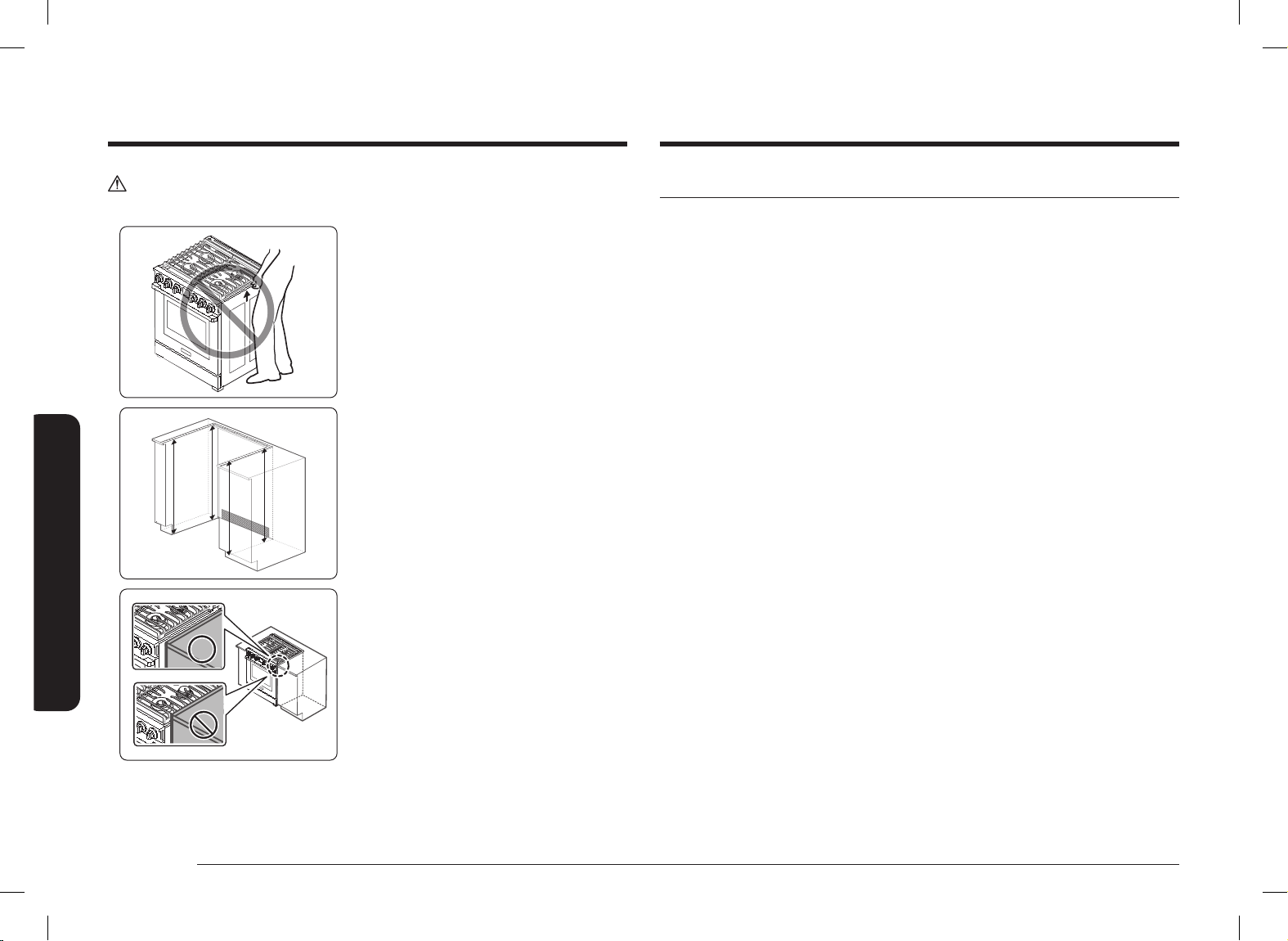
CAUTION
Do NOT lift or handle the unit by the cooktop frame.
1. The counter top around the cut-out
should be at and leveled (See hatched
area on Fig. 1).
2. Before installing the unit, measure
the heights of the two cabinet sides
(C1~C4), front and back (See Fig. 1)
from the oor to the top of the counter.
3. Level the range using the four leveling
legs so that the height from the oor
to the underside of the cooktop frame
is greater than the tallest cabinet
measurement by at least
1
/16”.
4. Slide the unit into the cabinet (DO NOT
PUSH THE UNIT HARD). Make sure the
center of the unit aligns with the center
of the cabinet cut-out.
5. The metal ange under each side of
the cooktop MUST be placed over the
cabinet countertop for proper unit
support. The cooktop should NOT rest
directly on the countertop or else it
could cause damage to the cooktop
voiding the warranty. Level the unit if
needed.
Gas requirements
Provide adequate gas supply
This range is designed to operate at a pressure of 5 in (13 cm) of water column on
natural gas or 10 in (25 cm) of water column on LP gas (propane or butane).
Make sure you are supplying your range with the type of gas for which it is
designed.
Do not attempt to convert the appliance from the gas specied in this manual to a
different gas without consulting the gas supplier.
This range is convertible for use on natural or propane gas. If you decide to use
this range on LP gas, conversion must be made by a qualied LP installer before
attempting to operate the range.
For proper operation, the pressure of natural gas supplied to the regulator must be
between 5 in and 13 in (13 cm and 33 cm) of water column.
For LP gas, the pressure supplied must be between 10 in and 13 in (25 cm and
33 cm) of water column.
When checking for proper operation of the regulator, the inlet pressure must be at
least 1 in (2.5 cm) greater than the operating (manifold) pressure as given.
The pressure regulator located at the inlet of the range manifold must remain in
the supply line regardless of whether natural or LP gas is being used.
A exible-metal appliance connector used to connect the range to the gas supply
line should have an I.D. of 0.5 in (1.3 cm) and be 5 ft (152 cm) in length for ease of
installation. In Canada, exible connectors must be single-wall metal connectors no
longer than 6 ft (183 cm) in length.
Do not kink or damage the exible metal tubing when moving the range.
C4
Flg.1
C3
C1
C2
INSTALL_DOP30T840GS_DA_DG68-01456A-00_EN.indd 16INSTALL_DOP30T840GS_DA_DG68-01456A-00_EN.indd 16 2022-10-06 오후 6:51:572022-10-06 오후 6:51:57
Loading ...
Loading ...
Loading ...