Loading ...
Loading ...
Loading ...

9
7.0 Setup and assembly
Open shipping container and check for shipping
damage. Report any damage immediately to your
distributor and shipping agent. Do not discard any
shipping material until the Lathe is assembled and
running properly.
Compare the contents of your container with the
following parts list to make sure all parts are intact.
Missing parts, if any, should be reported to your
distributor. Read the instruction manual thoroughly
for assembly, maintenance and safety instructions.
7.1 Shipping contents
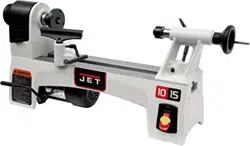
Carton contents (see Figure 3)
1 Lathe
1 Live center – A
1 Spur center – B
1 Knockout rod – C
1 Tool Support, 6” – D
1 Face Plate, 3” – E
1 Operating instructions & parts manual
1 Product registration card
Figure 3
Tools required for assembly:
3/16” hex key (“Allen” wrench)
Exposed metal areas of the lathe, such as bed,
spindle and quill, have been factory coated with a
protectant. This should be removed with a soft
cloth and a cleaner-degreaser. Clean the bed
areas under the headstock, tailstock and tool
support base. Do not use an abrasive pad, and do
not allow solvents to contact painted or plastic
areas.
7.2 Mounting lathe to stand/table
For effective and safe operation, the lathe must be
mounted to the optional stand (see section 14.0) or
a work table, using the four threaded holes in its
base (5/16-18 UNC threads). See section 6.1 for
correct spacing of the holes to be drilled in the
worktable.
7.3 Installing/removing face plate
Refer to Figure 4.
1. Insert knockout rod (C) into hole in spindle
collar (G) and hold it steady.
2. Mount face plate (F) to workpiece (see section
11.4), and screw face plate clockwise onto
spindle threads as far as it will go.
3. Use same procedure to remove faceplate,
screwing it counterclockwise off the spindle.
Figure 4
7.4 Installing/removing spur center
Refer to Figure 5.
1. Make sure mating surfaces of spur center and
spindle are clean.
2. Drive spur center into workpiece (see section
11.3.1).
3. Push spur center into spindle. NOTE: You do
not need to remove faceplate to install spur
center.
Figure 5
Loading ...
Loading ...
Loading ...