
Loading ...
Loading ...
Loading ...
4.Junior User Guidebook
menu; turn the M knob to choose Adjust. Press H2 button to choose the option "Self
Cal"; run the program after everything is ready.
Introduction to the Vertical System
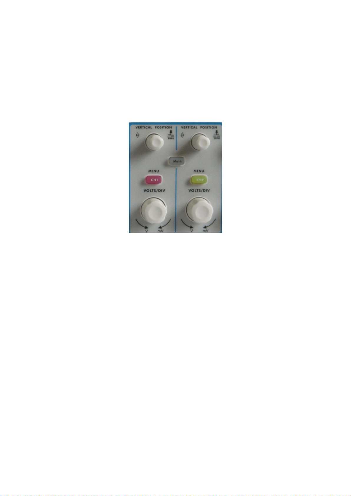
As shown in Figure 4-12, there are a few of buttons and knobs in VERTICAL
CONTROLS. The following practices will gradually direct you to be familiar with
the using of the vertical setting.
Figure 4-12 Vertical Control Zone
1. Use the button "VERTICAL POSITION" knob to show the signal in the center of
the waveform window. The "VERTICAL POSITION" knob functions the regulating
of the vertical display position of the signal. Thus, when the "VERTICAL
POSITION" knob is rotated, the pointer of the earth datum point of the channel is
directed to move up and down following the waveform.
Measuring Skill
If the channel is under the DC coupling mode, you can rapidly measure the DC
component of the signal through the observation of the difference between the wave
form and the signal ground.
If the channel is under the AC mode, the DC component would be filtered out. This
mode helps you display the AC component of the signal with a higher sensitivity.
Vertical offset back to 0 shortcut key
Turn the VERTICAL POSITION knob to change the vertical display position of
channel and press the position knob to set the vertical display position back to 0 as a
shortcut key, this is especially helpful when the trace position is far out of the screen
and want it to get back to the screen center immediately.
2. Change the Vertical Setting and Observe the Consequent State Information Change.
With the information displayed in the status bar at the bottom of the waveform
window, you can determine any changes in the channel vertical scale factor.
16
Loading ...
Loading ...
Loading ...