
Loading ...
Loading ...
Loading ...
4.Junior User Guidebook
11. The waveform of CH1.
12. The positions of two purple dotted line cursors measurements.
13. The yellow pointer shows the trigger level position for CH2.
14. The waveform of CH2.
15. The frequency of the trigger signal of CH1.
16. The frequency of the trigger signal of CH2.
17. It indicates the current function menu.
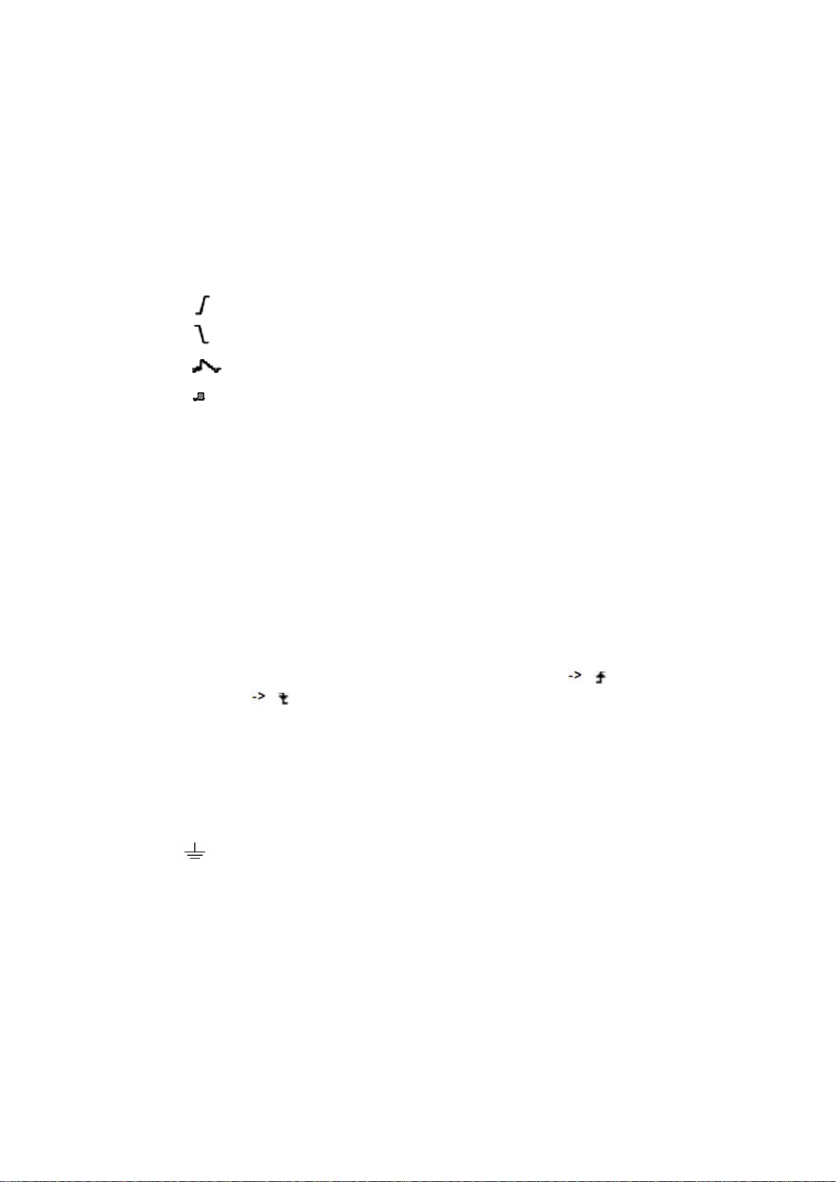
18/19. Current trigger type:
Rising edge triggering
Falling edge triggering
Video line synchronous triggering
Video field synchronous triggering
The reading shows the trigger level value of the corresponding channel.
20. The reading shows the window time base value.
21. The reading shows the setting of main time base.
22. The readings show current sample rate and the record length.
23. It indicates the measured type and value of the corresponding channel. "F" means
frequency, "T" means cycle, "V" means the average value, "Vp" the peak-peak
value, "Vk" the root-mean-square value, "Ma" the maximum amplitude value,
"Mi" the minimum amplitude value, "Vt" the Voltage value of the waveform's flat
top value, "Vb" the Voltage value of the waveform's flat base, "Va" the amplitude
value, "Os" the overshoot value, "Ps" the Preshoot value, "RT" the rise time value,
"FT" the fall time value, "PW" the +width value, "NW" the -Width value, "+D"
the +Duty value, "-D" the -Duty value, "PD" the Delay A B value and "ND"
the Delay A B value.
24. The readings indicate the corresponding Voltage Division and the Zero Point
positions of the channels.
The icon shows the coupling mode of the channel.
"—" indicates direct current coupling
"~" indicates AC coupling
" " indicates GND coupling
25. It is cursor measure window, showing the absolute values and the readings of the
two cursors.
26. The yellow pointer shows the grounding datum point (zero point position) of the
waveform of the CH2 channel. If the pointer is not displayed, it shows that this
channel is not opened.
27. The red pointer indicates the grounding datum point (zero point position) of the
waveform of the CH1 channel. If the pointer is not displayed, it shows that the
channel is not opened.
11
Loading ...
Loading ...
Loading ...