Handbrause losschrauben; den Kunststoffteil der Handbrause herausziehen und
den Schlauch mit einem 13 mm Schlüssel losschrauben (3) und den Schlauch
vollständig herausziehen und durch den neuen ersetzen, wobei man die Tätigkeiten
in umgekehrter Reihenfolge wiederholt.
ERSATZTEILE Abb. 6b
1 Kartusche Ø25 mm
2 Ring
3 Bediengriff
4 Brausekopf
5 Perlator
6 Befestigungsset
7 Brauseschläuche M15x1 - M15x1 L 2000
8 Anschlüßschläuche G3/8” L 470
9 Gewicht
INSTRUCCIONES DE MONTAJE, DE USO Y MANUTENCION
Fig. 1 - Antes de introducir el monomando en el agujero del fregadero, asegúrense
que la junta de base esté bien posicionada en su propio asiento y que los fl exibles de
alimentación estén bien atornillados al cuerpo del grifo. Posicionen el monomando
sobre el agujero del fregadero, orientando el caño de erogación hacia la cubeta del
fregadero.
Fig. 2 - Introduzcan el juego de fi jación según la secuencia indicada y
respectivamente:
· la junta moldurada y la brida en el caso de que se instale el monomando sobre un
fregadero de 3-4 cm de espesor;
· la junta moldurada, la brida triangular de plástico y la brida en el caso de que
se instale el monomando sobre un fregadero de acero inoxidable de 1-2 mm de
espesor.
Cierren hasta el fondo el tirante o la tuerca roscada. Conecten el fl exible al tubo de
salida interponiendo la junta de cierre.
Fig. 3 - Fijen el contrapeso de plomo sobre el tubo del fl exible a una distancia de 40
cm de la conexión del tubo de salida. Efectúen la conexión de los fl exibles a la red
de alimentación.
SUSTITUCIÓN DEL CARTUCHO
Fig. 4 - Antes de sustituir el cartucho, asegúrense que la conexión del agua esté
cerrada. Destornillen el tornillo de fi jación (A) utilizando una llave de allén, extraigan
la maneta (B) sacándola del cartucho (F). Levanten la virola cubre-cartucho (C)
utilizando la ranura de referencia (como indicado en la fi gura). Quiten el anillo
indicador (D), destornillen la virola de fi jación (E) y extraigan el cartucho (F) del
cuerpo del mezclador (G). Finalmente introduzcan el cartucho nuevo, asegurándose
que las dos clavijas de centraje se encuentren en su asiento y que las juntas estén
posicionadas correctamente.
SUSTITUCIÓN DEL FLEXIBLE DE LA DUCHA TELÉFONO
Fig. 5 - Saquen la ducha-teléfono de su alojamiento (1) y destornillen el aireador (2);
sucesivamente destornillen la ducha-teléfono del fl exible ayudándose con una llave
de allén de 10 mm (3). Bloqueen el fl exible con una llave de 13 mm, desensamblen
la conexión (4) y saquen el fl exible desacoplado. Vuelvan a ensamblar el conjunto
según el procedimiento inverso.
PIÉZAS DE REPUESTAS Fig. 6b
1 Cartucho Ø25 mm
2 Virola de fi jación
3 Palanca compléta
4 Ducha-teléfono compléta
5 Aerador
6 Juego de fi jación
7 Flexible por la ducha-teléfono M15x1-M15x1 L 2000
8 Flexibles de alimentación G3/8” L 470
9 Plomo de contrepeso
· the shaped gasket and fl ange in case the single lever group is installed on
a sink having thickness of 3-4 cm;
· the shaped gasket, the triangular plastic fl ange and the fl ange in case of a
stainless steel sink having thickness of 1-2 mm.
Tighten well the tie rod or the threaded nut. Connect the fl exible hose to the
outlet pipe interposing the gasket.
Fig. 3 - Fix the lead counterweight to the fl exible hose at a distance of approx.
40 cm from the connection to the outlet pipe. Proceed connecting the fl exible
hoses to the plumbing.
CARTRIDGE REPLACEMENT
Fig. 4 - Before carrying out this operation make sure that water connection
is closed. Unscrew the fastening screw (A) using an Allen wrench, take out
the handle (B), removing it from the cartridge (F). Lift the fi nishing ring nut (C)
using the reference notch (as indicated in the fi gure). Remove the indicator
ring (D), unscrew the fi xing ring nut (E) and take the cartridge (F) out form the
mixer body. Then put the new cartridge, verifying that the two centering pins
enter into the respective seats and that gaskets are well positioned.
REPLACEMENT OF THE FLEXIBLE OF THE HAND SHOWER
Fig. 5 - Pull the hand shower outwards from its place (1) and unscrew the
aerator (2), unscrew the hand shower from the fl exible by means of a 10mm
key keeping fi rm the fl exible with a 13mm key and disassemble the joint (3).
Pull out the disassembled fl exible. Finally reassemble the whole with the
opposite procedure.
SPARE PARTS Fig. 6b
1 Cartridge Ø25 mm
2 Metal ring
3 Complete lever
4 Complete Handshower
5 Aerator
6 Fastening set
7 Hose for handshower M15x1 - M15x1 L 2000
8 Supply hoses G3/8” L 470
9 Lead counterweight
MONTAGE-, WARTUNGS- UND GEBRAUCHSANNWEISUNG
Abb. 1 - Bevor Sie die Einhebel-Mischbatterie in die Bohrung des
Spülbeckens einführen, vergewissern Sie sich, dass die Basisdichtung
perfekt in ihrem Sitz positioniert ist und das die Versorgungsschläuche gut
am Armaturenkörper festgeschraubt sind. Die Einhebel-Mischbatterie auf der
Bohrung des Spülbeckens positionieren, wobei der Auslauf in Richtung des
Spülbeckens orientiert sein muß.
Abb. 2 - Anschließend den Befestigungssatz in der angegebenen Reihenfolge
einführen, und zwar:
· die geformte Dichtung und den Flansch, falls man die Einhebel-Mischbatterie
auf einem Spülbecken mit einer Dicke von 3-4 cm installiert;
· die geformte Dichtung, den dreieckigen Kunststofffl ansch und den Flansch,
falls man diese auf einem Inoxstahl-Spülbecken mit einer Dicke von 1-2
mm installiert.
Die eigens dafür vorgesehene Zugstange oder die gestrehlte
Schraubenmutter bis zum Anschlag festziehen. Schließt man Den Schlauch
an dem Rohrausgang an, wobei man die Dichtung dazwischen einlegt.
Abb. 3 - Das Gegengewicht aus Blei in einem Abstand von 40 cm vom
Anschluss des Ausgangsrohr an dem Schlauch fi xieren. Dann schließt man
die Schläuche an das Versorgungsnetz an.
AUSTAUSCHEN DER KARTUSCHE
Abb. 4 - Bevor man die Kartusche austauscht muß man sich vergewissern,
dass das Wasserversorgungsnetz geschlossen ist. Die Befestigungsschraube
(A) unter Einsatz eines Sechskantschlüssel losschrauben, dann den Griff (B)
herausziehen, indem man ihn von der Kartusche (F) abzieht. Die Nutmutter,
welche die Kartusche (C) abdeckt, entfernen, wobei man Druck auf die
eigens dafür vorgesehene Bezugsrille (entsprechend der Abbildung) ausübt.
Den Anzeigering (D) entfernen, die Befestigungsnutmutter (E) losschrauben
und die neue Kartusche (F) vom Körper der Mischbatterie (G) entfernen.
Schließlich eine neue Kartusche einsetzen, wobei man sich vergewissert,
dass sich die beiden Zentrierstifte in ihrem Sitz befi nden und das die
Dichtungen korrekt positioniert sind.
AUSTAUSCHEN VOM SCHLAUCH DER HANDBRAUSE
Fig. 5 - Die Handbrause herausziehen (1), den Perlator abschrauben (2).
Unter Einsatz eines 10mm Sechskantschlüssel den Kunststoffteil der
ET 38826 - R1
Art. 20577
PROGRAMMA MISCELAZIONE CUCINA
KITCHEN MIXING PROGRAM
PROGRAMME DU MITIGEUR POUR LA CUISINE
KÜCHEN-MISCHUNGSPROGRAMM
PROGRAMA MEZCLADORES COCINA
JUST
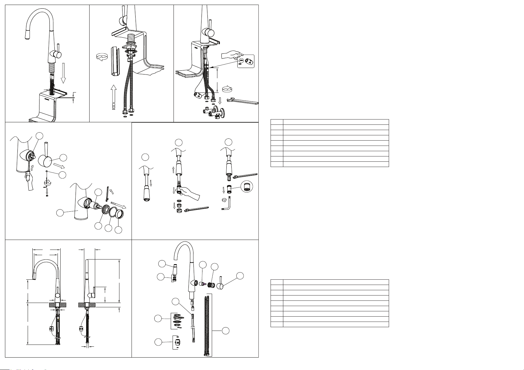
ISTRUZIONI DI MONTAGGIO, D’USO E MANUTENZIONE
Fig. 1 - Prima di inserire il monocomando nel foro del lavello assicurarsi che la guarnizione di base sia ben posizionata nella propria
sede e che i flessibili di alimentazione siano ben avvitati al corpo del rubinetto. Sistemare il monocomando sul foro del lavello
orientando la bocca di erogazione verso la vasca del lavello.
Fig. 2 - Inserire quindi il Kit di fissaggio nella sequenza indicata e rispettivamente:
· la guarnizione sagomata e la flangia nel caso si installi il monocomando su un lavello di spessore 3-4 cm;
· la guarnizione sagomata, la flangia triangolare in plastica e la flangia nel caso si installi il monocomando su un lavello in acciaio
inox di spessore 1-2 mm. Serrare a fondo l’apposito tirante o dado filettato. Collegare il flessibile al tubetto di uscita interponendo
la guarnizione di tenuta.
Fig. 3 - Fissare il contrappeso di piombo sul tubo del flessibile ad una distanza di 40 cm dall’attacco del tubetto di uscita. Procedere
al collegamento dei flessibili alla rete di alimentazione.
SOSTITUZIONE DELLA CARTUCCIA
Fig. 4 - Prima di sostituire la cartuccia, accertarsi che il raccordo dell’acqua sia chiuso. Svitare la vite di fissaggio (A) utilizzando
una chiave a brugola, estrarre quindi la maniglia (B) sfilandola dalla cartuccia (F). Sollevare la ghiera copricartuccia (C) facendo
leva ( come in figura) tramite l’apposita scanalatura di riferimento. Allontanare l’anello indicatore (D), svitare la ghiera di fissaggio
(E) e togliere la cartuccia (F) dal corpo del miscelatore (G). Infine introdurre la nuova cartuccia, accertandosi che le due spine di
centraggio siano nella loro sede e che le guarnizioni siano correttamente posizionate.
SOSTITUZIONE DEL FLESSIBILE DELLA DOCCETTA
Fig. 5 - Sfilare la doccetta dal proprio alloggiamento (1) e svitare l’aeratore (2), svitare la doccetta dal raccordo del flessibile
aiutandosi con una chiave a brugola da 10mm e tenendo fermo il flessibile con una chiave da 13mm disassemblare il raccordo (3)
e sfilare il flessibile completamente scollegato. Procedere inversamente per riassemblare il tutto.
PARTI DI RICAMBIO Fig. 6b
1 Cartuccia Ø25 mm
2 Ghiera
3 Maniglia completa
4 Doccetta completa
5 Aeratore
6 Set di fissaggio cucina
7 Flessibile per la doccetta M15x1 - M15x1 L 2000
8 Flessibili di alimentazione G3/8” L 470
9 Peso in piombo
INSTRUCTIONS DE MONTAGE, D’EMPLOI ET D’ENTRETIEN
Fig. 1 - Avant d’insérer le monocommande dans le trou de l’évier, il faut s’assurer que le joint de base est bien placé dans son
emplacement et que les flexibles d’alimentation sont bien vissés au corps du robinet. Il faut placer le monocommande sur le trou de
l’évier en orientant la bouche de distribution vers le bac de l’évier.
Fig. 2 - Insérer donc le kit de fixage dans la séquence indiquée et respectivement:
· le joint façonné et la bride si on installe le monocommande sur un évier d’une épaisseur de 3-4 cm;
· le joint façonné, la bride triangulaire en plastique et la bride dans le cas d’un évier en acier inox d’une épaisseur de 1-2 mm.
Serrer à fond le tirant ou l’écrou fileté. Il faut relier le flexible au tuyau de sortie en interposant le joint d’étanchéité.
Fig. 3 - Il faut fixer le contrepoids de plomb sur le tuyau du flexible à une distance de 40 cm du raccord du tuyau de sortie. Procéder
à la liaison des flexibles au réseau d’alimentation.
SUBSTITUTION DE LA CARTOUCHE
Fig. 4 - Avant d’effectuer la substitution de la cartouche, vérifier que la connexion de l’eau est fermée. Dévisser la vis de fixation
(A) utilisant une clé à griffe, extraire en suite la poignée (B) en la soulevant de la cartouche (F). Soulever la virole de finition (C) en
utilisant (comme indiqué en la figure) la rainure de référence. Quitter la bague d’indication (D), dévisser la virole de fixation (E) et
enlever la cartouche (F) du corps de mitigeur (G). Introduire enfin la cartouche nouvelle, en vérifiant que les deux pivots de centrage
entrent dans les sièges respectifs et que les garnitures sont bien positionnées.
SUBSTITUTION DU FLEXIBLE DE LA DOUCHETTE
Fig. 5 - Extraire la douchette dans la propre siège ( 1 ) et dévisser l’ aérateur ( 2 ), dévisser la partie de plastique de la douchette en
utilisant une clé anglaise de 10mm, extraire la partie en plastique de la douchette et dévisser avec une clé de 13mm et avec la clé
anglaise le flexible à substituer ( 3 ). Extraire complètement le flexible et répéter l’ opération selon l’ ordre inverse.
PIÉCES DE RECHANGE Fig. 6b
1 Cartouche Ø25 mm
2 Anneau de fixage
3 Levier complét
4 Douchette complét
5 Aerateur
6 Set de fixage
7 Flexible pour la douchette M15x1 - M15x1 L 2000
8 Flexibles de aliméntation G3/8” L 470
9 Poids en plomb
INSTALLATION, USE AND MAINTENANCE INSTRUCTIONS
Fig. 1 - Before inserting the single lever group in the hole of the sink, make sure that the base gasket is properly positioned in its
seat and that the flexible hoses are well tightened to the body of the tap. Place the single lever group in the hole of the sink, orienting
the spout toward the sink tank.
Fig. 2 - Insert the fixing kit with the indicated sequence, and respectively:
measures in mm - dimensions en mm - Maß im mm - dimensioni in mm - medidas en milímetros
Fig. 1 Fig. 2 Fig. 3
Ch. 45mm
Fig. 4
Ch. 19mm
Ø33.5min
40max
4
1
2
3
6
8
9
Fig. 6a Fig. 6b
217
256
412
150
99
Ø50
Ø33.5
40 MAX
565
221
G 3/8"
7
5
Fig. 5
B
C
D
E
F
G
A
C
Ch. 22mm
Ch. 10mm
1
2
3
Ch. 13mm
Ch. 28mm
Ch. 2.5mm
40 cm