mNSTALLATmONAND SERVICE MUST BE PERFORMED BY A QUAUFBED [NSTALLER.
IMPORTANT: SAVE FOR LOCAL ELECTRICAL mNSPECTOR'SUSE.
READ AND SAVE THESE [NSTRUCTmONS FOR FUTURE REFERENCE.
I F_ if the information in this manua[ is not followed exactly, a fire
or expJosion may resuJt causing property damage, personaJ injury or death.
FOR YOUR SAFETY:
Do not store or use gasoline or other flammable vapors and liquids in the
vicinity of this or any other app[iance. Refer to your serial plate for
-- WHAT TO DO JFYOU SMELL GAS: applicable agency certification
• Do not try to Hght any appliance.
• Do not touch any eJectrica[ switch; do not use any phone in your building.
Immediately ca[[ your gas supplier from a neighbor's phone. FoIIow the gas suppIier's instructions,
tf you cannot reach your gas supplier, ca[[ the fire department.
-- Installation and service must be performed by a qualified installer, service agency or the gas supplier,
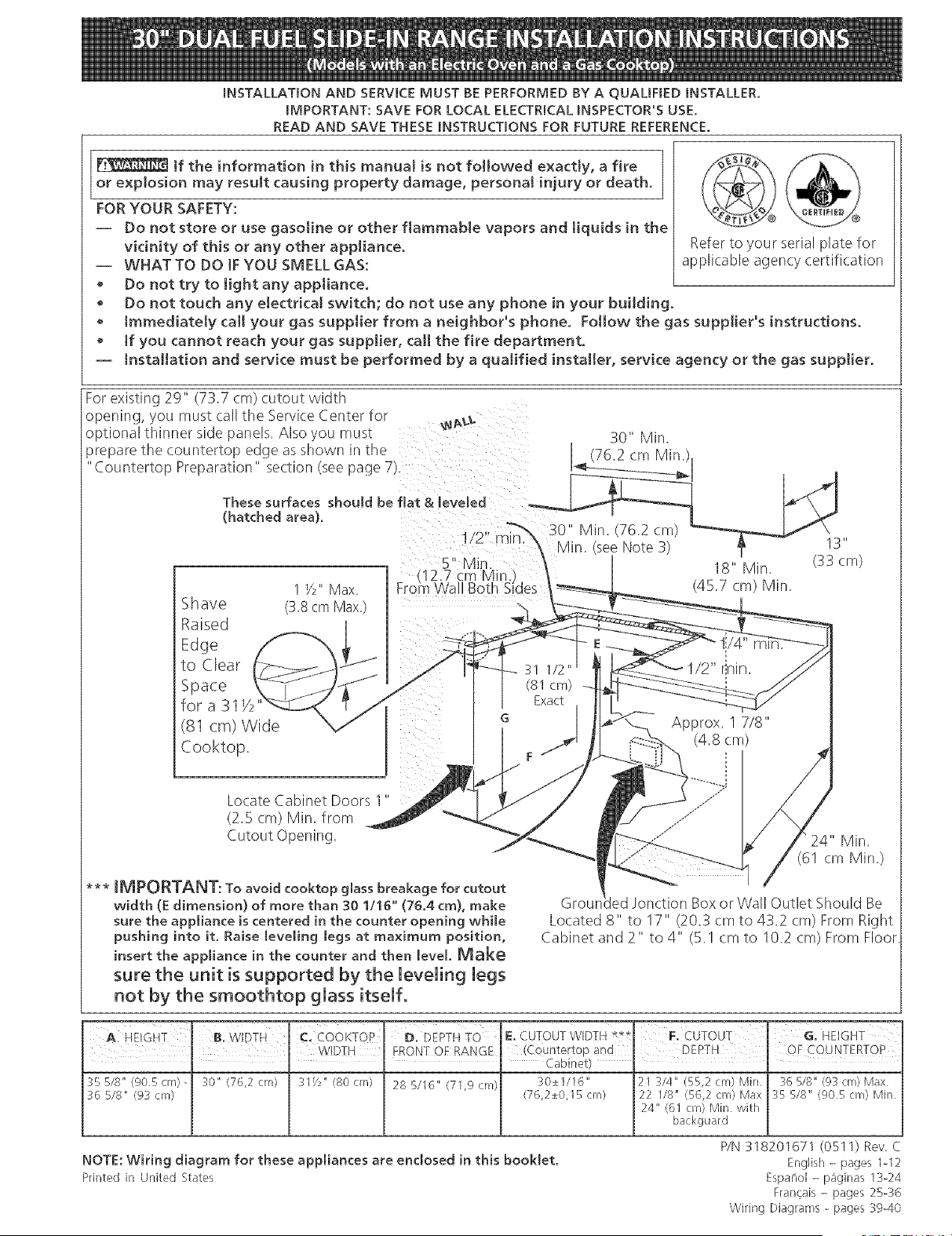
For existing 29" (73.7 cm) cutout width
opening, you must call the Service Center for
optional thinner side panels. Also you mus_
prepare the countertop edge as shown in tne
"Countertop Preparation" section (see page 7/.
30" Min.
76.2 cm Min.
These surfaces shouH be fiat & Jeveled
(hatched area).
Shave
Raised
Edge
to Clear
Space
for a 31 >2
(81 cm) Wide
Cooktop.
1 Y2"Max.
(3_8cm Max.)
Locate Cabinet Doors 1"
(2.5 cm) Min. from
Cutout Opening.
*** IMPORTANT: To avoid cooktop gmass breakage for cutout
width (E dimension) of more than 30 11!6" (76.4 cm), make
sure the appliance is centered in the counter opening while
pushing into it. Raise leveling legs at maximum position,
insert the appliance in the counter and then [eveL Make
sure the unit is supported by the leveling legs
not by the smoothtop glass itself.
Approx. 7/8"
(4.8 cm)
: _24" Mira
i / (61cmMin.)
Grour_ed Jonction Box or Wall Outlet Should Be
Located 8" to 17" (20.3 cm to 43.2 cm) From Right
Cabinet and 2" to 4" (5.1 cm to 10.2 cm) From Floor
I
C. COOKTOP D, DEPTH TO E. CUTOUT WIDTH **g F, CUTOUT G. HEIGHT
I I WIDTH FRONT QF RANGE (C0untertop and ' DEATH ' OF COUNTERTOP
' ' Cabinet)
355/8" @05cm)- :_0" (76,2 cm) :_1Y2"(80cm) 28 5116" (71,9cm) 30±1116" 21 3/4" {55,2cm) Min, %518"(93cm) Max
36 518" (9_ crn) (76,2±0,15cm) 22 I18" (56,2 cm) Max 35 5/8" (905cm) Min
24" {61 cm) Min with
backguard
NOTE: Wiring diagram for these appliances are enclosed in this booklet.
Printed in United States
P/N 318201671 (0511) Rev C
English - pages 1-12
Espano[ - p_ginas 13-24
Fran_ais - pages 25-_6
Wiring Diagrams - pages 3g-40

NOTE:
1, Do not pinch the power supply cord or the flexible gas conduit between the range and the wall,
2. Do not seal the range to the side
cabinets.
3.24" (61 cm) minimum clearance
between the cooktop and the bottom
of the cabinet when the bottom of
wood or metal cabinet is protected by
not less than Y4" (0.64 cm) flame
retardant millboard covered with not
less than No. 28 MSG sheet metal,
0.015"(0.4 ram) stainless steel,
0.024"(0.6 ram) aluminum, or 0.020"
(0.5 mm) copper.
30" (762 cm) minimum clearance when
the cabinet is unprotected.
4. For cutouts below 22 7/8"(58.1 cm),
appliance will slightly show out of the
cabinet.
5.Atlow at least 19 Y4" (48.9 cm)
clearance for door depth when it is
open.
Door Open
A
Panel
IMPORTANT: Cabinet and countertop
width should match the cutout width.
E
E
22 7/8"(58,1 cm) rain,
23 1/4"(59,05 cm) max,
(see Note 4)
1 (2.86 cm)
FRONT OF
Ref.
" Cabinet)
% 5/8" (90,5 crn) - 30" (76,2 crn) :_1Y2"(80 crn) 28 5/I6" (71,9 cm) 30±I/16" 21 W4" (55,2 cnl) Min 36 5/8" (93 cm) Max
36 5/8" (9:_cm) (76,2±0,15 cm) 22 1/8" (56,2 cm) Max :_ 5/8" (905 cm) Min
24" (61 cm) Min with
backguard
2
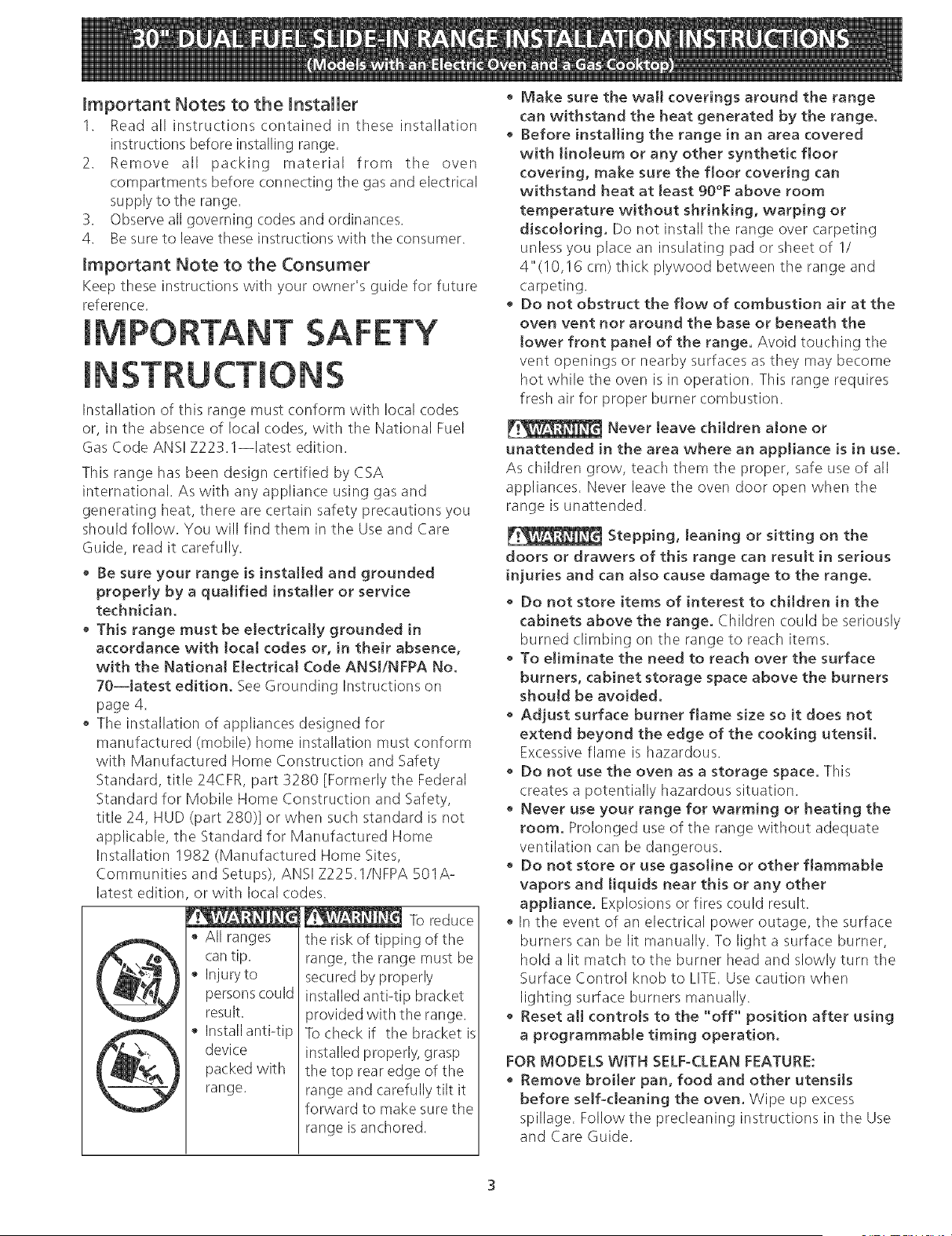
Important Notes to the Installer
1. Readall instructionscontainedin theseinstallation
instructionsbeforeinstallingrange.
2. Removeall packing material from the oven
compartmentsbeforeconnectingthegasandelectrical
supplytotile range.
3. Observeallgoverningcodesandordinances.
4. Besureto leavetheseinstructionswithtileconsumer.
Important Note to the Consumer
Keep these instructions with your owner's guide for future
reference.
IMPORTANT SAFETY
[NSTRU S
Installation of this range must conform with local codes
or, in the absence of local codes, with the National Fuel
Gas Code ANS! Z223. l--latest edition.
This range has been design certified by CSA
international. As with any appliance using gas and
generating heat, there are certain safety precautions you
should follow. You will find them in the Use and Care
Guide, read it carefully.
• Be sure your range is instai[ed and grounded
properly by a qualified installer or service
technician.
• This range must be electrically grounded in
accordance with toca[ codes or, in their absence,
with the National EJectrica[ Code ANSJ/NFPA No.
7O--Jatest edition. See Grounding Instructions on
page 4.
• The installation of appliances designed for
manufactured (mobile) home installation must conforra
with Manufactured Home Construction and Safety
Standard, title 24CFR, part 3280 [Formerly the Federal
Standard for Mobile Home Construction and Safety,
title 24, HUD (part 280)] or when such standard is not
applicable, the Standard for Manufactured Home
Installation 1982 (Manufactured Home Sites,
Communities and Setups), ANSI Z225.1/NFPA 501A-
latest edition or with local (.odes.
To reduce
• All ranges
can tip.
• Injury to
persons could
result.
• Install anti-tip
device
packed with
range.
the risk of tipping of tile
range, the range must be
secured by properly
installed anti-tip bracket
provided with the range.
To check if the bracket is
installed properly, grasp
the top rear edge of the
range and carefully tilt it
forward to make sure the
range is anchored.
Make sure the wal[ coverings around the range
can withstand the heat generated by the range.
• Before installing the range in an area covered
with linoleum or any other synthetic floor
covering, make sure the floor covering can
withstand heat at [east 9B°F above room
temperature without shrinking, warping or
discoloring. Do not install tile range over carpeting
unless you place an insulating pad or sheet of 1/
4"(10,!6 cm) thick plywood between the range and
carpeting.
• Do not obstruct the flow of combustion air at the
oven vent nor around the base or beneath the
tower front panel of the range. Avoid touching the
vent openings or nearby surfaces as they may become
hot while tile oven is in operation. This range requires
fresh air for proper burner combustion.
Never leave children alone or
unattended [n the area where an appliance [s [n use.
As children grow, teach them the proper, safe use of all
appliances. Never leave the oven door open when the
range is unattended.
Stepping, leaning or sitting on the
doors or drawers of this range can result in serious
injuries and can also cause damage to the range.
• Do not store items of interest to children in the
cabinets above the range. Children could be seriously
burned climbing on the range to reach items.
To eliminate the need to reach over the surface
burners, cabinet storage space above the burners
shouId be avoided.
Adjust surface burner flame size so it does not
extend beyond the edge of the cooking utensil.
Excessive flame is hazardous.
Do not use the oven as a storage space. This
creates a potentially hazardous situation.
Never use your range for warming or heating the
room. Prolonged use of the range without adequate
ventilation can be dangerous.
• Do not store or use gasoline or other fJammabIe
vapors and liquids near this or any other
appliance. Explosions or fires could result.
In the event of an electrical power outage, the surface
burners can be lit manually. To light a surface burner,
hold a lit match to the burner head and slowly turn the
Surface Control knob to LITE. Use caution when
lighting surface burners manually.
• Reset all controis to the "off" position after using
a programmable timing operation.
FOR MODELS WITH SELF-CLEAN FEATURE:
• Remove broiler pan, food and other utensiJs
before self-cleaning the oven. Wipe up excess
spillage. Follow the precleaning instructions in the Use
and Care Guide.
Power Supply Cord Kit (U.S.A.)
The user is responsible for connecting the power supply
cord to the connection block located behind the back
panel access cover.
This appliance may be connected by means of
permanent "hard wiring" (flexible armored or
nonmetallic shielded copper cable), or by means of a
power supply cord kit. Only a power supply cord kit rated
at 125/250 volts minimum, 40 amperes and marked for
use with ranges shall be used. See chart for cord kit
connection opening size information. Cord must have
either 3 or 4 conductors.
For mobile homes, new installations, recreational
vehicles, or areas where local codes do not permit
grounding through neutral, a 4 conductor power supply
cord kit rated at 125/250 volts minimum, 40 amperes
and marked for use with ranges should be used (see
Figure 5).
Terminals on end of wires must be either closed loop or
open-end spade lugs with upturned ends. Cord must
have strain-relief clamp.
See below for 3 or 4 conductor wire connection.
Range Connection Opening Size Chart
Refer to chart below for proper range connection opening size and power
supply cord kit ampere rating information. See serial plate on appliance for
kilowatt rating data.
Seeserial Plate on the
Appliance for KW Rating
120/240 Volts 120/208 Volts
0- 8.7 kw 0- 7.8 kw
8.8-16.5kw 7.9- 12.5kw
16.6-22.5kw 12.6-18.5kw
Cord Kit
Ampere
Rating
30 Amp
40 Amp
50 Amp
Diameter (inches (cm)) of
Appliance Connection Opening
Direct
Cord Kit Connection
1 1/8(2.9) 7/8(2.2)
1 3/8 (3.5) 1 1/8 (2.9)
1 318 (3.5) 1 318 (3.5)
NOTE: Electric Slideqn Range is shipped from factory
with 1 1/8" (2.9 cm) dia. hole as shown on figure 4. If a
larger hole is required, punch out the knockout.
Risk of fire or electrical shock exists if
an incorrect size range cord kit is used, the
Installation Instructions are not followed, or the
strain retief bracket is discarded.
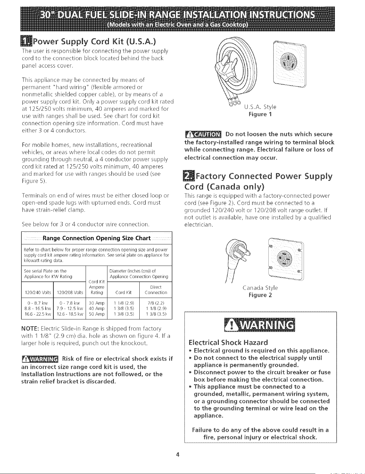
U.S.A. Style
Figure 1
Do not loosen the nuts which secure
the factory-installed range wiring to terminat block
while connecting range. Electrical faiture or toss of
electrical connection may occur.
Factory Connected Power Supply
Cord (Canada only)
This range is equipped with a factory-connected power
cord (see Figure 2). Cord must be connected to a
grounded 120/240 volt or 120/208 volt range outlet. If
not outlet is available, have one installed by a qualified
electrician.
Canada Style
Figure 2
Electrical Shock Hazard
Electrical ground is required on this appliance.
• Do not connect to the electrical supply untit
appliance is permanentJy grounded.
• Disconnect power to the circuit breaker or fuse
box before making the electrical connection.
This appliance must be connected to a
grounded, metallic, permanent wiring system,
or a grounding connector should be connected
to the grounding terminal or wire lead on the
appliance.
Failure to do any of the above could result in a
fire, personal injury or electrical shock.
EJectricaJ Connection to the Range
(U,S.A.)
This appliance is manufactured with the neutral terminal
connected to the frame.
Note: Refer to the wiring diagram in the center pages of
this manual.
Three Conductor Wire Connection to Range
(The 3-conductor cord or cable must be replaced with a
4-conductor cord or cable where grounding through the
neutral conductor is prohibited in new installations,
mobile homes, recreational vehicles or in other areas
where local codes do not permit neutral grounding)
If local codes permit connection of the frame grounding
conductor to the neutral wire of the copper power supply
cord (see Figure 4):
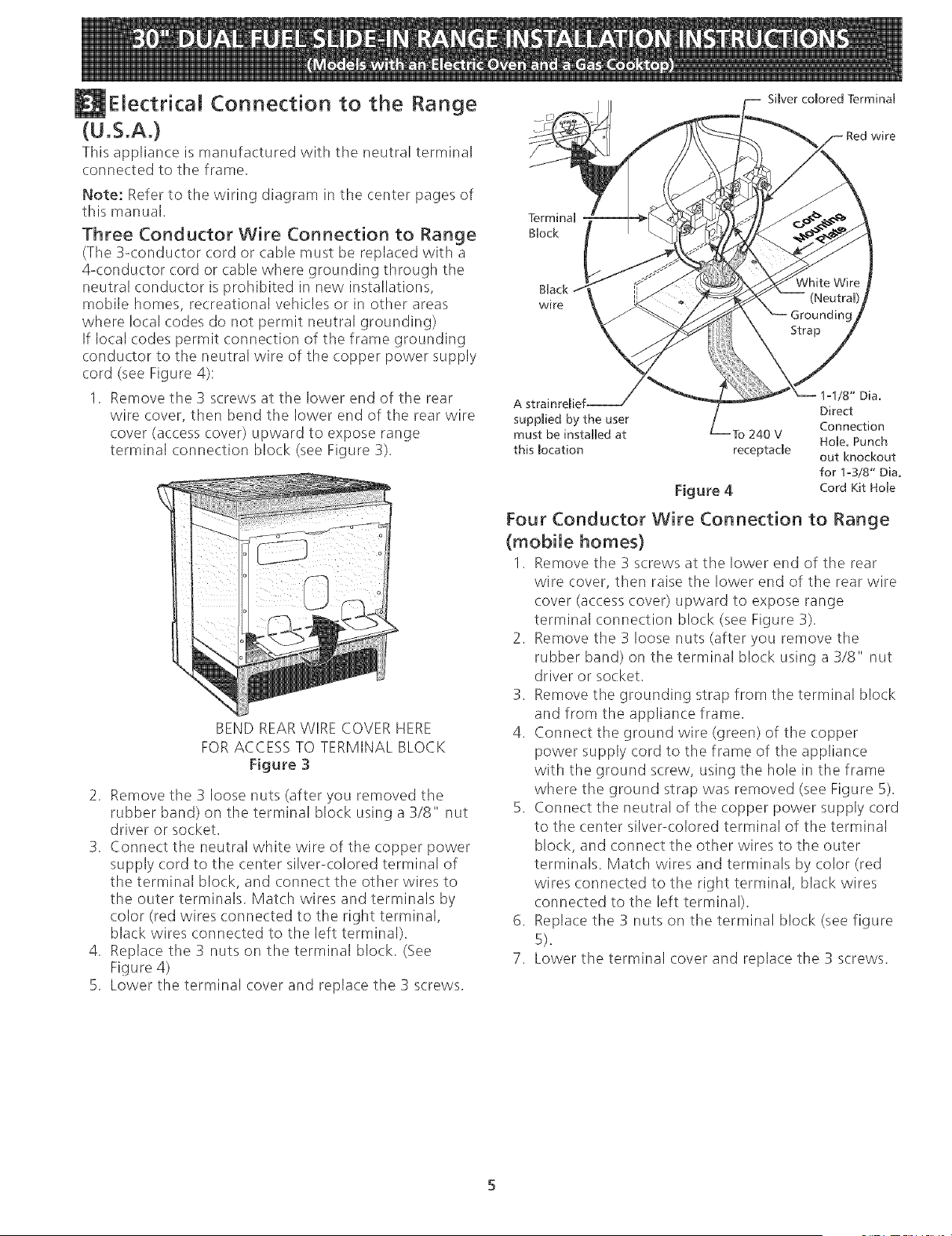
1. Remove the 3 screws at the lower end of the rear
wire cover, then bend the lower end of the rear wire
cover (access cover) upward to expose range
terminal connection block (see Figure 3).
BEND REARWIRE COVER HERE
FOR ACCESS TO TERMINAL BLOCK
Figure 3
2. Remove the 3 loose nuts (after you removed the
rubber band) on the terminal block using a 3/8" nut
driver or socket.
3. Connect the neutral white wire of the copper power
supply cord to the center silver-colored terminal of
the terminal block, and connect the other wires to
tile outer terminals. Match wires and terminals by
color (red wires connected to the right terminal,
black wires connected to the left terminal).
4. Replace the 3 nuts on the terminal block. (See
Figure 4)
5. Lower the terminal cover and replace the 3 screws.
Simverco[ored TerminaU
Red wire
Terminal
gUock
BUack
wire
Direct
suppRied by the user
Connection
must be installed at Fo 240 V
Hole. Punch
this [ocation receptacle out knockout
for 1o3/8" Dia.
Figure 4 Cord Kit Hole
Four Conductor Wire Connection to Range
(mobile homes)
1. Remove the 3 screws at the lower end of tile rear
wire cover, then raise the lower end of the rear wire
cover (access cover) upward to expose range
terminal connection block (see Figure 3).
2. Remove the 3 loose nuts (after you remove the
rubber band) on tile terminal block using a 3/8" nut
driver or socket.
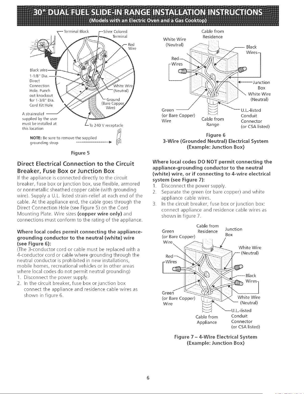
3. Remove the grounding strap from the terminal block
and from the appliance frame.
4. Connect the ground wire (green) of the copper
power supply cord to the frame of the appliance
with the ground screw, using the hole in the frame
where the ground strap was removed (see Figure 5).
5. Connect the neutral of the copper power supply cord
to the center silver-colored terminal of the terminal
block, and connect the other wires to the outer
terminals. Match wires and terminals by color (red
wires connected to the right terminal, black wires
connected to the left terminal).
6. Replace the 3 nuts on the terminal block (see figure
5).
7. Lower tile terminal cover and replace the 3 screws.
Brock
TerminaF
Red
Wire
1-1/8"
Direct
Connection
HoFe. Punch
out knockout
for 1-3/8" Dia.
Cord Kit Hole
A strainreFief
supplied by the user
must be installed at
this Focation
ro 240 v receptacle
NOTE: Be sure to remove the supphed
grounding strap
Figure 5
Direct Electrical Connection to the Circuit
Breaker, Fuse Box or Junction Box
If the appliance is connected directly to the circuit
breaker, fuse box or junction box, use flexible, armored
or nonmetallic sheathed copper cable (with grounding
wire). Supply a U.L listed strain-relief at each end of the
cable. At the appliance end, tile cable goes through the
Direct Connection Hole (see Figure 5) on the Cord
Mounting Plate. Wire sizes (copper wire only} and
connections must conform to the rating of the appliance.
Where local codes permit connecting the appliance-
grounding conductor to the neutral (white} wire
(see Figure 6}:
(The 3-conductor cord or cable must be replaced with a
4<onductor cord or cable where grounding through the
neutral conductor is prohibited in new installations,
mobile homes, recreational vehicles or in other areas
where local codes do not permit neutral grounding)
1. Disconnect tile power supply.
2. In the circuit breaker, fuse box or junction box
connect the appliance and residence cable wires as
shown in figure 6.
White Wire
(Neutram)
Cable from
Residence
Black
WiresI
)n
Box
White Wire
(Neutral)
Green U,L,-misted
(or Bare Copper) Conduit
Wire Cable from Connector
Range (or CSA misted)
Figure 6
3-Wire (Grounded Neutral} Electrical System
(Example: Junction Box}
Where tocaJ codes DO NOT permit connecting the
appliance-grounding conductor to the neutral
(white} wire, or if connecting to 4-wire electrical
system (see Figure 7}:
1. Disconnect the power supply.
2. Separate the green (or bare copper) and white
appliance cable wires.
3. In the circuit breaker, fuse box or iunction box:
connect appliance and residence cable wires as
shown in figure 7.
Cable from
Green Residence Junction
(or Bare Copper) Box
Red_
Wires
White Wire
ack
Green
(or Bare Copper) White Wire
Wire (Neutram)
U.Loqisted
Cable from Conduit
Appmiance Connector
(or CSA misted)
Figure 7 - 4oWire Electrical System
(Example: Junction Box)
Cabinet Construction
To eliminate the risk of burns or fire by
reaching over heated surface units, do not have cabinet
storage space above the range. If there is cabinet
storage space above range, reduce risk by installing a
range hood that projects horizontally a minimum of 5"
(12.7 cm) beyond tile bottom of tile cabinet.
Countertop Preparation
• The cooktop sides of the range fit over the cutout edge
of your countertop.
• If you have a square finish (fiat) countertop, no
countertop preparation is required. Cooktop sides lay
directly on edge of countertop.
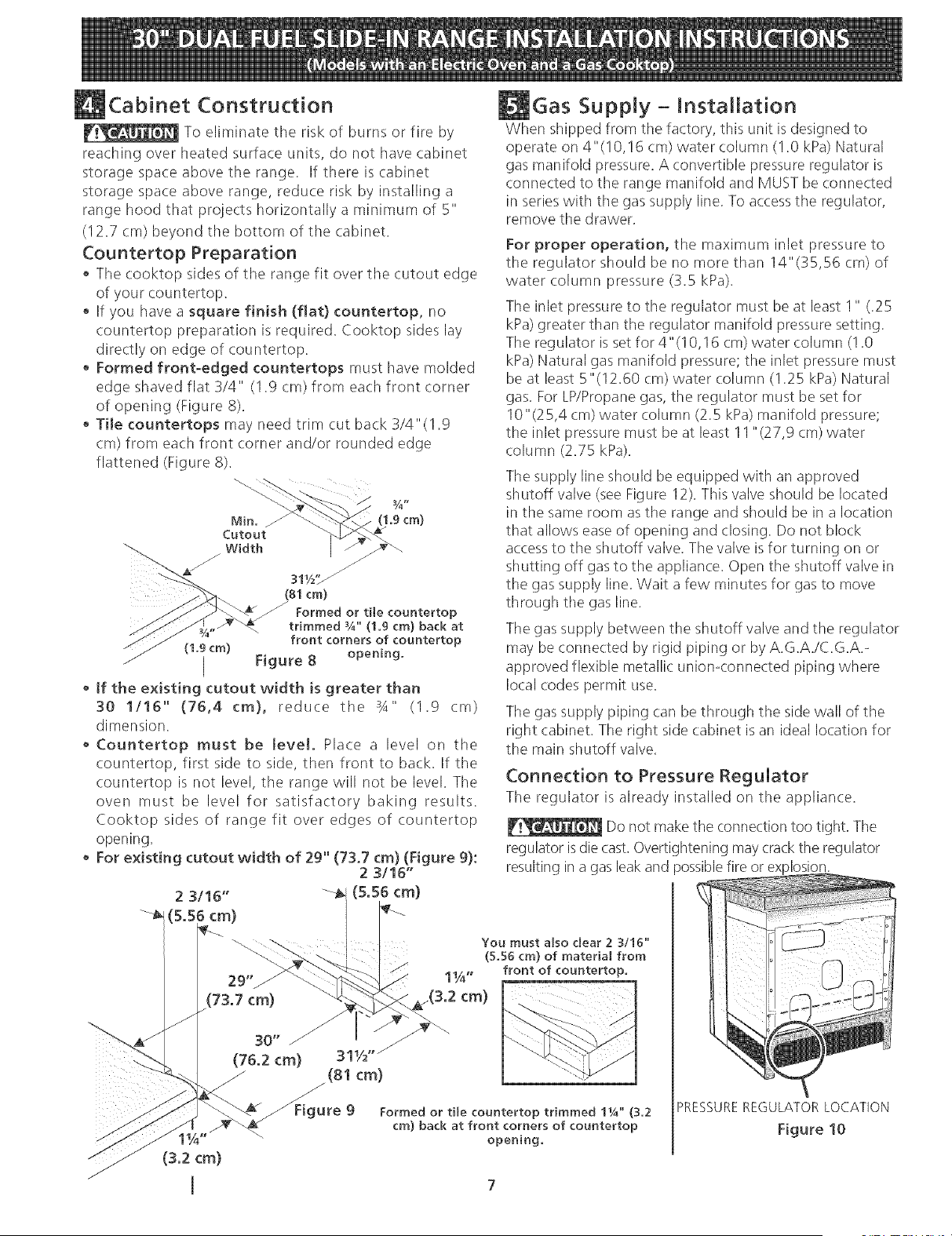
• Formed front-edged countertops must have molded
edge shaved flat 3/4" (1.9 cm) from each front corner
of opening (Figure 8).
• Tile countertops may need trim cut back 3/4"(1.9
cm) from each front corner and/or rounded edge
flattened (Figure 8).
(1.9 cm)
(1,9cm)
311/2'_
(81cm)
Formed or tile countertop
trimmed ¾" (1.9 cm) back at
front corners of countertop
Figure 8 opening.
• tf the existing cutout width is greater than
30 1/16" (76,4 cm), reduce the 3A" (1.9 cm)
dimension.
Countertop must be level. Place a level on the
countertop, first side to side, then front to back. If the
countertop is not level, tile range will not be level. The
oven must be level for satisfactory baking results.
Cooktop sides of range fit over edges of countertop
opening.
For existing cutout width of 29" (73,7 cm) (Figure g):
2 3/16"
(5.56 cm)
29" 1_/_"
(73.7 cm) _(3.2 cm)
You must also dear 2 3/16"
(5.56 cm) of material from
front of countertop.
_re Formed or tile countertop trimmed lYg' (3.2
9
cm) back at front corners of countertop
opening,
Gas Supply- Installation
When shipped from tile factory, this unit is designed to
operate on 4"(10,16 cm) water column (I .0 kPa) Natural
gas manifold pressure. A convertible pressure regulator is
connected to the range manifold and MUST be connected
in series with tile gas supply line. To access tile regulator,
remove tile drawer.
For proper operation, the maximum inlet pressure to
the regulator should be no more than 14"(35,56 cm) of
water column pressure (3.5 kPa).
The inlet pressure to the regulator must be at least 1" (.25
kPa) greater than tile regulator manifold pressure setting.
The regulator is set for 4" (! 0,16 cm) water column (I .0
kPa) Natural gas manifold pressure; the inlet pressure must
be at least 5"(12.60 cm) water column (!.25 kPa) Natural
gas. For LP/Propane gas, the regulator must be set for
10"(25,4 cm) water column (2.5 kPa) manifold pressure;
the inlet pressure must be at least 11 "(27,9 cm) water
column (2.75 kPa).
The supply line should be equipped with an approved
shutoff valve (see Figure 12). This valve should be located
in tile same room as the range and should be in a location
that allows ease of opening and (:losing. Do not block
accessto the shutoff valve. The valve is for turning on or
shutting off gas to the appliance. Open the shutoff valve in
the gas supply line. Wait a few minutes for gas to move
through tile gas line.
Tile gas supply between the shutoff valve and the regulator
may be connected by rigid piping or by A.G.A./C.G.A.-
approved flexible metallic uniomconnected piping where
local codes permit use.
The gas supply piping can be through the side wall of the
right cabinet. The right side cabinet is an ideal location for
the main shutoff valve.
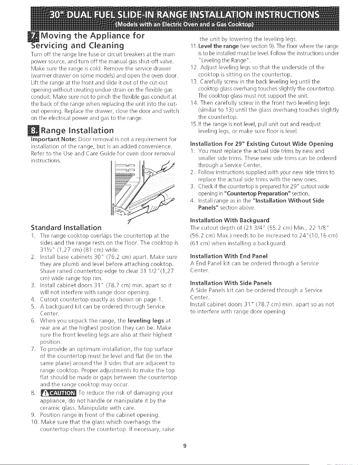
Connection to Pressure Regulator
Tile regulator is already installed on the appliance.
Do not make the connection too tight. The
regulator is die cast.Overtightening may crack the regulator
resulting in a gas leak and )ossiblefire or explosion.
PRESSURE REGULATOR LOCATION
Figure 10

Manual GAS FLOW Pressure
Shutoff Hare _ Hare ReguHator
VaHve Union Union
On, _J t t t
k,_ NippHe FHexibHe NippHe.........................
Access
Off Connector
Cap
All connections must be wrench4ightened
Figure 11
Assemble the flexible connecter from the gas supply pipe
to the pressure regulator in the following order:
1. manual shutoff valve (not supplied)
2. 1/2" nipple (not supplied)
3. 1/2" flare union adapter (not supplied)
4. flexible connector (not supplied)
5. 1/2" flare union adapter (not supplied)
6. 1/2" nipple (not supplied)
7. pressure regulator (supplied)
The gas supply line to the shutoff valve should be
1/2"(1,27 cm) or 3/4"(1.9 cm) solid pipe.
The user must know the location of the main shutoff
valve and have easy access to it.
When using flexible gas conduit on the range, allow
suffi(ient slack to pull the range outside the cutout for
cleaning or servicing.
NOTE: Do not allow the flexible conduit to get pinched
between the wall and the range. To visually check,
remove tile range drawer.
Usepipe-joint compound made for use with Natural and
LP/Propane gas to seal all gas connections. If flexible
connectors are used, be certain connectors are not kinked.
Open position
Figure 12
Tile supply line must be equipped with an approved
manual shutoff valve. This valve should be located in the
same room as the range and should be in a location that
allows ease of opening and closing. Do not block access
to the shutoff valve. The valve is for turning on or
shutting off gas to the appliance.
Once regulator is in place, open the shutoff valve in the
gas supply line. Wait a few minutes for gas to move
through the gas line.
Leak testing of the appliance shah be conducted
according to the manufacturer's instructions.
Check for leaks. After connecting the range to the gas supply,
check the system for leakswith a manometer. If a manometer
is not available, turn on tile gas supply and use a liquid leak
detector at all joints and connections to check for leaks.
Do not use a flame to check for leaks
from gas connections. Checking for leaks with a flame
may result in a fire or explosion.
All openings in the wall or floor where tile range is to be
installed must be sealed.
Tighten all connections if necessary to prevent gas
leakage in the cooktop or supply line.
Disconnect this range and its individual shutoff
valve from tile gas supply piping system during any
pressure testing of tile system at test pressures greater
than 1/2 psig (3.5 kPa or 14"(35,56 cm) water column).
Isolate the range from the gas supply piping system
by closing its individual manual shutoff valve during any
pressure testing of tile gas supply piping system at test
pressures equal to or less than 1/2 psig (3.5 kPa or
14"(35,56 cm) water column).
LPiPropane Gas Conversion
This appliance can be used with Natural gas or LP/Propane
gas. It isshipped from the factory for usewith natural gas.
If you wish to convert your range for use with LP/Propane
gas, use the supplied fixed orifices located in a bag
containing the literature marked "FOR LP/PROPANEGAS
CONVERSION." Follow the instructions packaged with
the orifices.
The conversion must be performed by a qualified service
technician in accordance with the manufacturer's
instructions and all local codes and requirements. Failure
to follow these instructions could result in serious injury
or property damage. The qualified agency performing
this work assumes responsibility for the conversion.
Failure to make the appropriate
conversion can result in personal injury and property
damage.
MOVing the Appliance for
rvicing and Cleaning
Turn off the range line fuse or circuit breakers at the main
power source, and turn off the manual gas shut-off valve.
Make sure the range is (:old. Remove the service drawer
(warmer drawer on some models) and open the oven door.
Lift the range at the front and slide it out of the cut-out
opening without creating undue strain on the flexible gas
conduit. Make sure not to pinch the flexible gas conduit at
the back of the range when replacing the unit into the cut-
out opening. Replace the drawer, close the door and switch
on the electrical power and gas to tile range.
Range Installation
Important Note: Door removal is not a requirement for
installation of the range, but is an added convenience.
Refer to the Use and Care Guide for oven door removal
instructions.
f
Standard Installation
1.
The range cooktop overlaps the countertop at the
sides and the range rests on the floor. The cooktop is
31Y_" (1,27 cm) (81 cm) wide.
2. Install base cabinets 30" (76.2 cm) apart. Make sure
they are plumb and level before attaching cooktop.
Shave raised countertop edge to clear 31 1/2 "(I ,27
cm) wide range top rim.
3. Install cabinet doors 31 " (78.7 cm) rain. apart so it
will not interfere with range door opening.
4. Cutout countertop exactly as shown on page I.
5. A backguard kit can be ordered through Service
Center.
6. When you unpack tile range, tile leveling legs at
rear are at the highest position they can be. Make
sure the front leveling legs are also at their highest
position.
7. To provide an optimum installation, the top surface
of the countertop must be level and flat (lie on the
same plane) around the 3 sides that are adjacent to
range cooktop. Proper adjustments to make the top
flat should be made or gaps between the countertop
and the range cooktop may occur.
8. _ To reduce the risk of damaging your
appliance, do not handle or manipulate it by the
ceramic: glass. Manipulate with care.
9. Position range in front of tile cabinet opening.
10. Make sure that the glass which overhangs the
countertop clears the countertop. If necessary, raise
the unit by lowering the leveling legs.
11.Level the range (seesection 9). The floor where the range
isto be installed must be level. Follow the instructions under
"Leveling tile Range".
12. Adjust leveling legs so that the underside of the
cooktop is sitting on tile countertop.
13. Carefully screw in tile back leveling leg until the
cooktop glass overhang touches slightly the countertop.
The cooktop glass must not support the unit.
14. Then carefully screw in tile front two leveling legs
(similar to !3) until the glass overhang touches slightly
the countertop.
15.1fthe range is not level, pull unit out and readjust
leveling legs, or make sure floor is level.
Installation For 29" Existing Cutout Wide Opening
I. You must replace the actual side trims by new and
smaller side trims. These new side trims can be ordered
through a Service Center.
2. Follow instructions supplied with your new side trims to
replace the actual side trims with the new ones.
3. Check if the countertop is prepared for 29" cutout wide
opening in "Countertop Preparation" section.
4. Install range as in the "installation Without Side
Panels" section above.
Installation With Backguard
The cutout depth of (21 3/4" (55.2 cm) Min., 22 1/8"
(56.2 cm) Max.) needs to be increased to 24"(!0,16 cm)
(61 cm) when installing a backguard.
Installation With End Panel
A End Panel kit can be ordered through a Service
Center.
Installation With Side Panels
A Side Panels kit can be ordered through a Service
Center.
Install cabinet doors 31 " (78.7 cm) min. apart so as not
to interfere with range door opening.
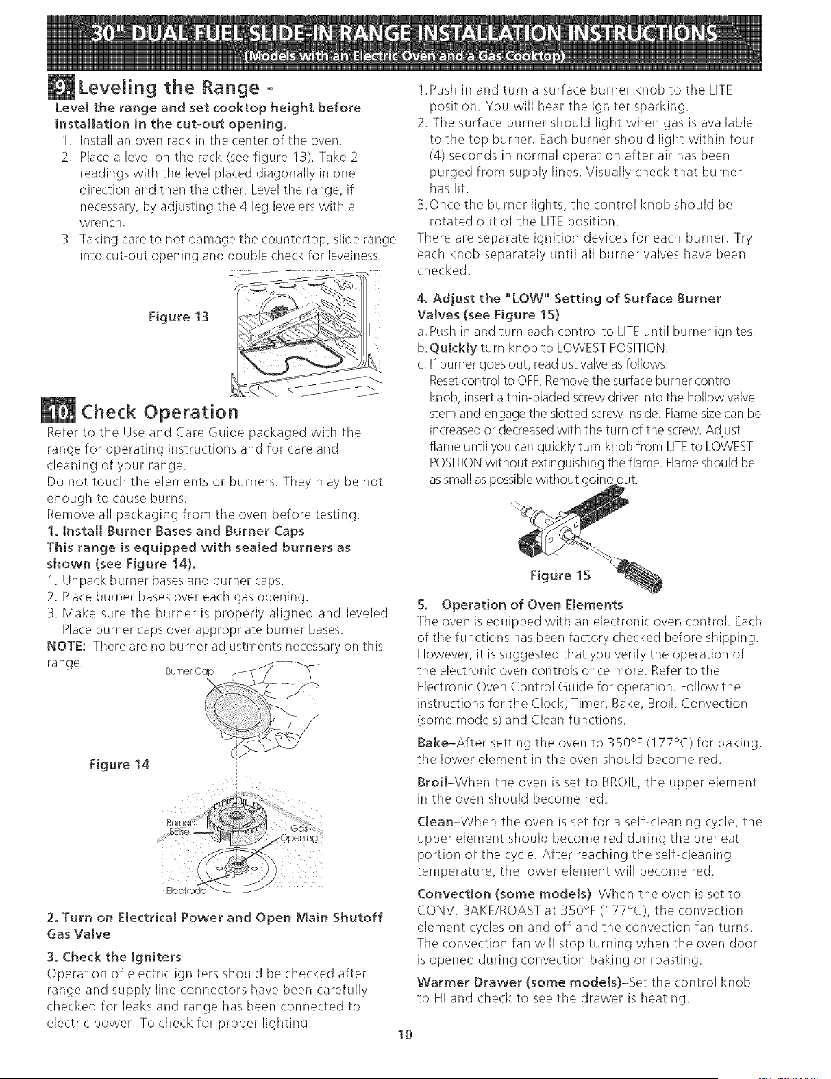
Leveling the Range -
Level the range and set cooktop height before
installation in the cut-out opening,
1. Install an oven rack in the center of tile oven.
2. Place a level on the rack (see figure 13). Take 2
readings with the level placed diagonally in one
direction and then the other. Level the range, if
necessary, by adjusting tile 4 leg levelers with a
wrench.
3. Taking care to not damage the countertop, slide range
into cut-out opening and double check for levelness.
1.Push in and turn a surface burner knob to the LITE
position. You will hear the igniter sparking.
2. The surface burner should light when gas is available
to the top burner. Each burner should light within four
(4) seconds in normal operation after air has been
purged from supply lines. Visually check that burner
has lit.
3.Once the burner lights, the control knob should be
rotated out of the LITE position.
There are separate ignition devices for each burner. Try
each knob separately until all burner valves have been
checked.
Figure 13
/
Check Operation
Refer to the Use and Care Guide packaged with the
range for operating instructions and for care and
(.leaning of your range.
Do not touch the elements or burners. They may be hot
enough to cause burns.
Remove all packaging from tile oven before testing.
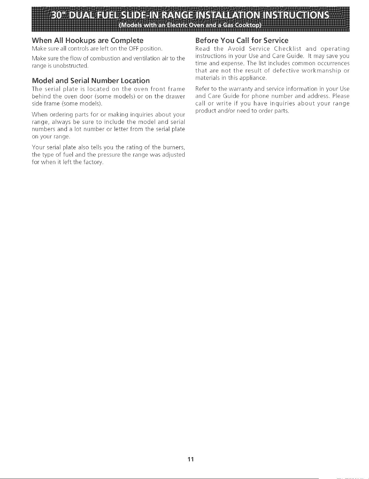
1. install Burner Bases and Burner Caps
This range is equipped with sealed burners as
shown (see Figure !@.
1. Unpack burner basesand burner caps.
2. Place burner bases over each gas opening.
3. Make sure the burner is properly aligned and leveled.
Place burner caps over appropriate burner bases.
NOTE: There are no burner adjustments necessary on this
range.
Burner Cap (
Figure 14
4. Adjust the "LOW" Setting of Surface Burner
Valves (see Figure ! S)
a.Push in and turn each control to LITEuntil burner ignites.
b.QukkJy turn knob to LOWESTPOSITION.
c. If burner goes out, readjust valve asfollows:
Resetcontrol to OFF.Removetile surface burner control
knob, inserta thin-bladed screw driver into tile hollow valve
stem and engage the slotted screw inside. Flame size can be
increasedor decreasedwith the turn of the screw. Adjust
flame until you can quickly turn knob from LITEto LOWEST
POSITIONwithout extinguishing tile flame. Flameshould be
as smallas possiblewithout goin_
Figure 15
5. Operation of Oven Elements
Tile oven is equipped with an electronic: oven control. Each
of the functions has been factory checked before shipping.
However, it is suggested that you verify the operation of
the electronic oven controls once more. Refer to tile
Electronic Oven Control Guide for operation. Follow the
instructions for the Clock, Timer, Bake, Broil, Convection
(some models) and Clean functions.
Bake-After setting the oven to 350% (I 77°C) for baking,
tile lower element in the oven should become red.
Broil-When the oven is set to BROIL, the upper element
in tile oven should become red.
Opening
Electrode
2. Turn on Electrical Power and Open Main Shutoff
Gas Va[ve
3. Check the Igniters
Operation of electric igniters should be checked after
range and supply line connectors have been carefully
checked for leaks and range has been connected to
electric power. To check for proper lighting:
Clean-When the oven is set for a self-cleaning cycle, tile
upper element should become red during the preheat
portion of the cycle. After reaching tile self-cleaning
temperature, tile lower element will become red.
Convection (some models)-When the oven is set to
CONV. BAKE/ROAST at 350% (I 77°C), the convection
element cycles on and off and the convection fan turns.
The convection fan will stop turning when the oven door
is opened during convection baking or roasting.
Warmer Drawer (some mode[s}-Set the control knob
to HI and check to see the drawer is heating.
10
When All Hookups are Complete
Make sure all controls are left on the OFF position.
Make sure the flow of combustion and ventilation air to the
range is unobstructed.
Model and Serial Number Location
The serial plate is located on the oven front frame
behind the oven door (some models or on the drawer
side frame (some models).
When ordering parts for or making inquiries about your
range, always be sure to include the model and serial
numbers and a lot number or letter from the serial plate
on your range.
Your serial plate also tells you the rating of the burners,
the type of fuel and the pressure the range was adjusted
for when it left the factory.
Before You Call for Service
Read tile Avoid Service Checklist and operating
instructions in your Use and Care Guide. It may save you
time and expense. The list includes common occurrences
that are not the result of defective workmanship or
materials in this appliance.
Refer to the warranty and service information in your Use
and Care Guide for phone number and address. Please
call or write if you have inquiries about your range
product and/or need to order parts.
11
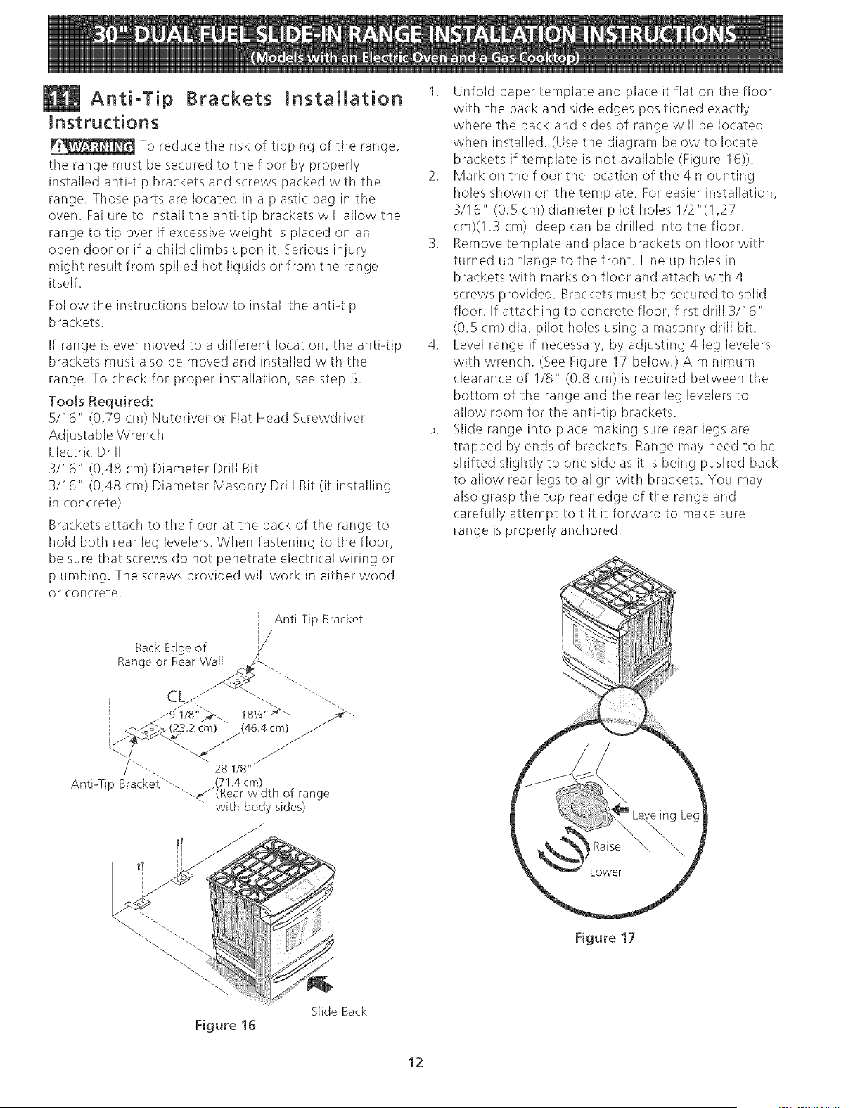
Anti-Tip Brackets JnstaJJation
instructions
To reduce the risk of tipping of the range,
the range must be secured to the floor by properly
installed anti-tip brackets and screws packed with the
range. Those parts are located in a plastic, bag in the
oven. Failure to install the anti-tip brackets will allow the
range to tip over if excessive weight is placed on an
open door or if a child climbs upon it. Serious injury
might result from spilled hot liquids or from the range
itself.
Follow the instructions below to install the anti-tip
brackets.
If range is ever moved to a different location, the anti-tip
brackets must also be moved and installed with the
range. To check for proper installation, see step 5.
TooJs Required:
5/16" (0,79 cm) Nutdriver or Flat Head Screwdriver
Adjustable Wrench
Electric Drill
3/16" (0,48 cm) Diameter Drill Bit
3/16" (0,48 cm) Diameter Masonry Drill Bit (if installinc
in concrete)
Brackets attach to the floor at the back of tile range to
hold both rear leg levelers. When fastening to tile floor,
be sure that screws do not penetrate electrical wiring or
plumbing. The screws provided will work in either wood
or concrete.
Anti-Tip Bracket
/
BackEdgeof /
Range or Rear Wall _,-.. "--.
.,--di/s'M, _s,/4"_'_ _'-,
i _ (23.2 c_m) "" (46.4cm) /
Anti-Tip Bracket"-_.. .(71.4 cm)
"--..<.,_(Rear width of range
" with body sides)
1. Unfold paper template and place it flat on the floor
with the back and side edges positioned exactly
where the back and sides of range will be located
when installed. (Use the diagram below to locate
brackets if template is not available (Figure 16)).
2. Mark on the floor the location of the 4 mounting
holes shown on the template. For easier installation,
3/16" (O.S cm) diameter pilot holes I/2"(!,27
cm)(!.3 cm) deep can be drilled into the floor.
3. Remove template and place brackets on floor with
turned up flange to the front. Line up holes in
brackets with marks on floor and attach with 4
screws provided. Brackets must be secured to solid
floor. If attaching to concrete floor, first drill 3/16"
(O.S cm) dia. pilot holes using a masonry drill bit.
4. Level range if necessary, by adjusting 4 leg levelers
with wrench. (See Figure 17 below.)A minimum
clearance of 1/8" (0.8 cm) is required between the
bottom of the range and the rear leg levelers to
allow room for tile anti-tip brackets.
S. Slide range into place making sure rear legs are
trapped by ends of brackets. Range may need to be
shifted slightly to one side as it is being pushed back
to allow rear legs to align with brackets. You may
also grasp tile top rear edge of tile range and
carefully attempt to tilt it forward to make sure
range is properly anchored.
Figure 17
Figure 16
Slide Back
12
LA [NSTALAaON Y EL SERVIC[O DEBEN SER EFECTUADOS POR UN [NSTALADOR CAUF[CADO°
[MPORTANTE: GUARDE ESTAS [NSTRUCC[ONES PARA USO DEL INSPECTOR LOCAL DE ELECTRIC[DAD.
LEA Y GUARDE ESTAS [NSTRUCC[ONES PARA REFERENC[A FUTURA.
m
@
@
@
@
Si [a [nformad6n contenida en este manual no es seguida exactamente, 1
puede ocurrir un incendio o exp[osi6n causandoda_os materiales,[esi6npersonal o [a muerte.
1
PARASUSEGURDAD:
-- No a[maceneni utilke gasolina u otros vaporesy [iquidos inflamables en [a proximidad de
_steo de cua[quier otto artefacto.
QUEDEBEHACERSIPERCmBEOLORA GAS:
No trate de encender ningQn artefacto.
No toque n[ngQninterruptor el@trico; no use ningQn tel_fono en su edifido.
Refierase a su placa de
serie para la certificaciOn
de la agencia aplicable
Llamea su proveedorde gasdesdeel te[_fono de un vedno. Slga[as[nstruccionesdel proveedor de gas.
Sino [ogra comunicarse con su proveedor de gas, [lame a[ departamento de bomberos.
Lainstalacibn y el servicio de mantenimiento deben set efectuados pot un instalador califkado, [aagencia de servicio o el
proveedor de gas.
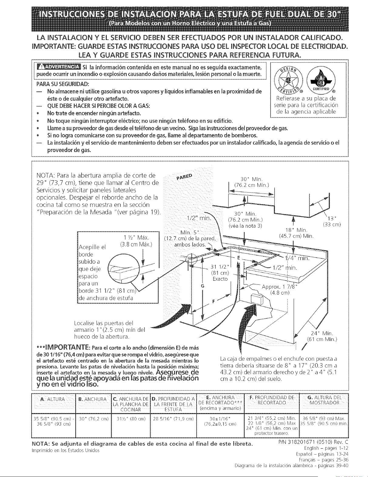
NOTA: Para la abertura amplia ae torte ae
29" (73,7 cm), tiene que Ilamar al Centro de
Servicios y solicitar paneles laterales
opcionales. Despejar el reDorae ancnc ae a
cocina tal como se muestra en la secoon
"Preparaci6n de la Mesada "(ver p_igna gk
Acepille el
horde
subido a
que deje
espacio
para un
horde 31 1/2" (81 cr
de anchura de estufa
___ 30" Min,
1/2" (76,2 cm Min,) \I 3"
(v__a[a nota 3) (33 cm)
18" Min
MJn. 5
(45,7 cm) Min.
12.7 cm) de la parea,
BI
Localise las puertas del
armario I"(2.5 cm) rain del
hueco de la abertura.
***IMPORTANTE: Parael corte a [o ancho (dimensi6n E)de m_S
de 301/16" (76,4 cm) para evitar que se rompa el vidrio, asegurese que
el artefacto est_ centrado en [a abertura de [a mesada mientras [o
presiona. Levante [as patas de nive[aci6n hasta [a posicion m&xima;
inserte el artefacto en [a mesada y [ueqo nive[e. Aseqt_rese de
que la unidad est.e apoyada en [as patas de 5ivelad6n
y no en ei vmermoimso.
Lacaja de empalmes o el enchufe (:on puesta a
tierra deberla situarse de 8" a 17" (20.3 cm a
43.2 cm) del armario derecho y de 2" a 4" (5.1
cm a 10.2 cm) del suelo.
B. ANCHURA C, ANCHURA DEA. ALTURA D. RROFUND[DAD A
35 5/8" (905 cm) 30" (76,2 cm) 31/2" (80 cm) 28 B/16" (71,9 crn) 30±1/16"
:_6 5/8" (93 cm) (76,2±0, I5 cm)
E. ANCHURA
DE RECORTADQ*tt
(encima y armario)
F. PROFUNDiDAD DE G. ALTURA DEL
RECORTADO . MOSTRADOR
21 314" (55,2 cm) Min, 36 5/8" @3 cm) Max
22 1/8" (56,2 era) Max 35 5/8" (905cm) min
24" (61 cnl) Min con un
protector trasero
NOTA: Se adjunta el diagrama de cables de esta cocina al final de este libreta. PIN 318201671 (0510) Rev C
Imprimido en los Estados Unidos English - pages 1-12
Espai_o[ - pBginas 13-24
Fran_ais - pages 25-36
Diagrama de la instalaciOn alambrica - paginas 3%40
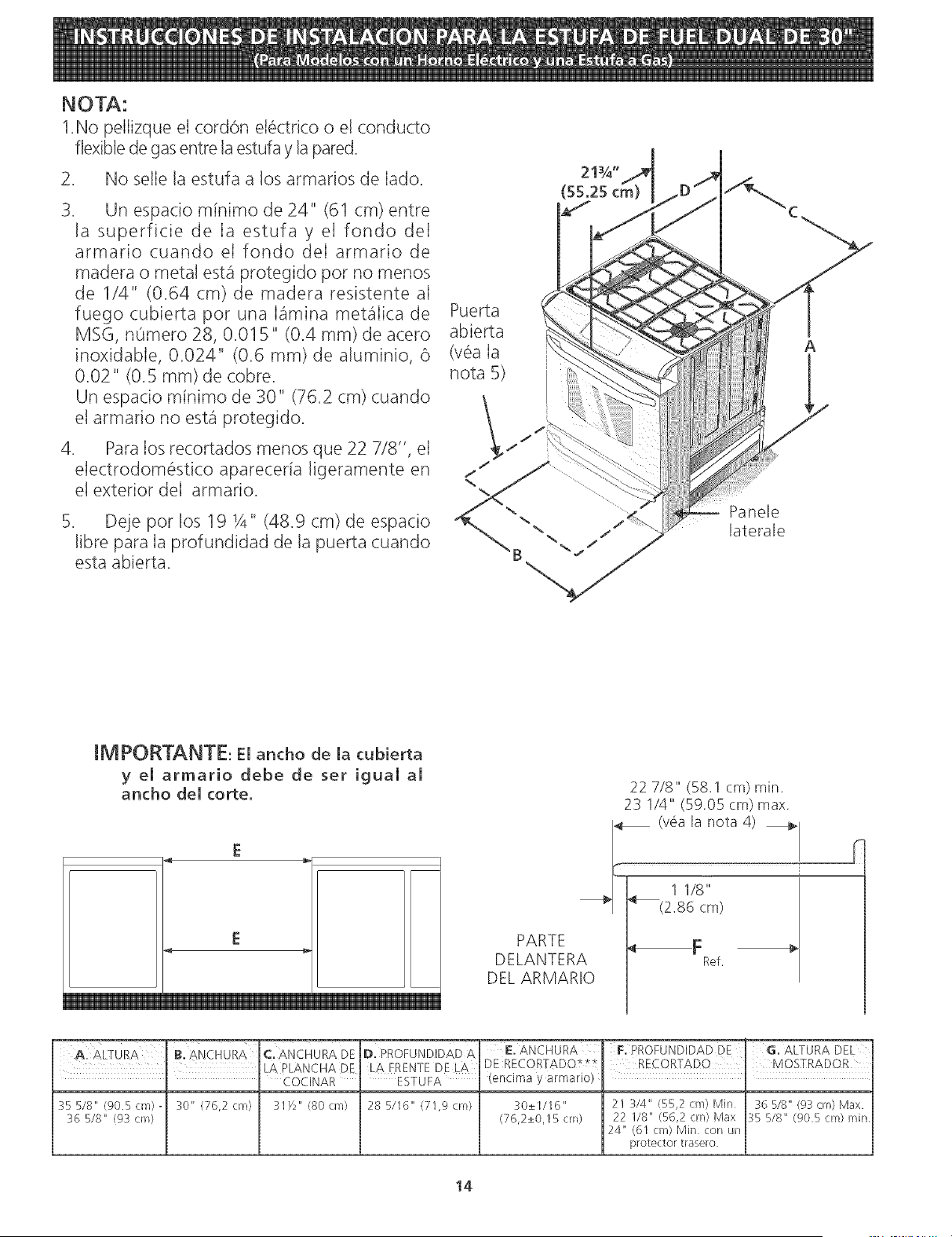
NOTA:
1.No pelIizque el cord6n el_ctrico o el conducto
flexible de gas entre la estufa y la pared.
No selle la estufa a los armarios de Iado.
3. Un espacio minimo de 24" (61 cm) entre
la superficie de Ia estufa y el fondo deI
armario cuando et fondo deI armario de
madera o metal est,1 protegido pot no menos
de 1/4" (0.64 cm) de madera resistente aI
fuego cubierta por una himina met_Iica de
MSG, nOmero 28, 0.015" (0.4 mm) de acero
inoxidable, 0.024" (0.6 ram) de aluminio, 6
0.02" (0.5 ram) de cobre.
Un espacio mfnimo de 30" (762 cm) cuando
el armario no est_ protegido.
4. Para los recortados menos que 22 7/8", el
etectrodom6stico aparecerla ligeramente en
el exterior deI armario.
Deje pot los 19 Y4" (48.9 cm) de espacio
libre para Ia profundidad de la puerta cuando
esta abierta.
Puerta
abierta
(v_a Ia
nota 5)
21¾"
(55.25 cm
Panele
laterale
A
IMPORTANTE: El ancho de la cubierta
y el armario debe de ser igual al
ancho del torte.
E
E
PARTE
DELANTERA
DEL ARMARIO
22 7/8" (58.1 cm) rain.
23 1/4" (59.05 cm) max.
_ (v6a la nota 4)
.... ]
/ 1 1/8"
_| _(2.86 cm)
F
Ref.
c SNcHuRADE
' LA PLANCHA DE
COCINAR
35 5/8" (90.5 cm) 30" (76,2 cm) 31Y2" (80 cm}
36 5/8" (9_ cm)
II). PROFUNDIDAD A' E. ANCHURA
LAFRENTE DELA DE RECORTADO*_
ESTUFA (encima y armario)
28 B/ld" (71,g cm) 30±1/I6"
(76,2±0,15 crn)
F. PROFUNDIDAD DE G. ALTURA DEL
21 :_/4" (55,2 cm) Min 36 5/fi" (g3 cm) Max
22 1/8" (56,2 crn) Max 3B B/8" (g0Bcm}min
24" (6I cm) Min con un
protector trasero
14
Notas importantes para el [nsta[ador
1. Lea todas las instrucciones contenidas en este manual
antes de instalar la estufa,
2. Saque todo e! material usado en el embalaje del
compartimiento del homo antes de conectar el
suministro electrico o de gas a la estufa.
3, Observe todos los c0digos y reglamentos pertinentes.
4, Deje estas instrucciones con el comprador.
Nota Importante para el Consumidor
Conserve estas instrucciones y el Manual del Usuario para
referencia futura.
INSTRUCCIONES DE
SEGURIDAD
Instalaci6n de esta estufa debe cumplir con todos los
c6digos locales, o en ausencia de c6digos locales con el
C6digo National de Gas Combustible ANSI Z223,1--
01tima ediciOn,
El diseflo de esta estufa ha sido certificado por la CSA
International, En este comoen cualquierotroartefacto
que use gas y genere calor, hay ciertas precauciones de
seguridad que usted debeseguir. Estasser_in
encontradas en el Manual del Usuario, lea!o
cuidadosamente.
Asegurese de que la estufa sea instalada y
conectada a tierra en forrna apropiada por un
instalador calificado o por un tecnico.
Esta estufa debe ser etectricarnente puesta a tierra
de acuerdo con los c6digos locales, o en su
ausencia, con el Cbdigo Electrico National ANSI/
NFPA No, 70, ultirna edition, Vea las instrucciones
para la puesta a tierra en la pagina 15.
• La instalaci0n de aparatos dise_ados para instalaciOn
en casas prefabricadas (mOviles) debe conformar con el
Manufactured Home Construction and Safety Standard,
titulo 24CFR, parte 3280 [Anteriormente e! Federal
Standard for Mobil Home Construction and Safety,
titulo 24, HUD (parte 280)] o cuando tal estandar no se
aplica, el Standard for Manufactured Home Installation
1982 (Manufactured Home sites, Communities and
Setups), ANSI Z225,1/NFPA 501A-edici0n m_s reciente,
o con los c0digos locales.
• Todas las
estufas
pueden
volcarse.
Esto podria
resultar en
lesiones
personales,
®Instale el
dispositivo
antivuelcos
que se ha
empacado
junto con
esta estufa.
Para reducir el riesgo de
que se vuelque la estufa,
hay que asegurarla
adecuadamente co!o
candole los soportes
antivuelco que se
proporcionan. Para
comprobar si estos estan
instalados y apretados en
su lugar como se debe,
ase el horde trasero
superior de la estufa y
cuidado samente incline la
hacia adelante para
asegurar que la estufa se
ancle.
15
Antes de instalar la estufa en un Mea cuyo piso
este recubierto con IinSleo u otro tipo de piso
sintetico, asegQrese de que estos puedan resistir
una ternperatura de pot 1o rnenos 90°F sobre la
ternperatura arnbiental sin provocar encogirniento,
deforrnadOnodecoloradOn. No instale laestufa
sobre una alfombra a! menos que coloque una plancha
de material aislante de pot Io menos 1/4 pulgada,
entre la estufa y la alfombra.
AsegQrese de que el material que recubre las
paredes alrededor de la estufa, pueda resistir et
calor generado por la estufa.
No obstruya el flujo del aire de combustion en la
ventilation del homo ni tarnpoco alrededor de la
base o debajo del panel inferior delantero de la
estufa. Evite tocar lasaberturaso a'reascercanas de
la ventilaci0n, ya que pueden estar muy calientes
durante el funcionamiento del horno, La estufa
requiere aire fresco para la combustion apropiada de
los quemadores.
_i_Nunca deje ni_os solos o
desatendidos en un Mea donde un artefacto est_
siendousado, Amedida que los ni_oscrecen,
enseff_eles e! uso apropiado y de seguridad para todos los
artefactos, Nuncadeje la puerta de! homoabierta
cuando la estufa esta" desatendida,
W!_No se pare, apoye o siente en las
puertas o ca jones de esta estufa pues puede resultar
en serias lesiones y puede tambi_n causar da_o a la
estufa.
• No alrnacene articulos que puedan interesar a los
ni_os en los gabinetessobre la estufa. Los nitros
pueden quemarse seriamente tratando de trepar a la
estufa para alcanzar estos articulos.
• Los gabinetes de alrnacenarniento sobre la estufa
deben ser evitados, para elirninar la necesidad de
tenet que pasar sobre los quernadores superiores
de la estufa para Ilegar a ellos,
Ajuste el tarna_o de la llama de los quernadores
superiores de tal rnanera que esta no sobrepase el
bordede los utensilios decocinar. La llama
excesiva es peligrosa.
No use el homo corno espacio de alrnacena]e. Esto
crear_ una situaci0n potencialmente peligrosa.
Nunca use la estufa para calentar el cuarto. El uso
prolongado de la estufa sin la adecuada ventilaci0n
puede resultar peligroso.
No alrnacene ni utilice gasolina u otros vapores y
liquidos inflarnab_es en la proxirnidad de este o de
cualquier otto artefacto etectrico. Puede provocar
incendio o explosion.
En caso de una interruption del servicio electrico, es
pasible de encender los quemadores de superficie a
mano. Para encender un quemador de suoerficie,
acerque un fOsforo encendido del cabezal det
quemador, y gire delicadamente el botOn de control de
superficie a LITE (encendido). Tener cuidado al
encender los quemadores a mano.
A]uste todos los controles a la position "OFF"
(apagada) despues de haber hecho una operacion
con tiernpo prograrnado,
PARA MODELOS AUTOLIMPIANTES:
Saque la asadera, alirnentos o cualquier otto
utensilio antes de usar el ddo de autolirnpieza del
homo, Limpietodoexceso de derrame dealimentos.
Siga las instrucciones de prelimpiado en el Manual del
Usuario.
Estuche de cable del suministro
emectrico (U.S.A.)
El utilizador es responsable de la conexi6n del cable del
suministro electrico al bloque de conexi6n situado detras
del panel de acceso.
Este electrodomestico puede set conectado pot medio de
una "conexiOn directa" de cables permanentes (cable
blindado flexible o no metalico recubierto de cobre), o pot
medio de un ensamblaje de cordon de suministro electrico.
Solamente un ensamblaje de (:ordd)nde suministro electrico
con regimen de 125/250 voltios minimo, 40 amperios y
marcado para uso con cocinas debe set utilizado. Vea la
tabla (pagina prc_xima)para information sobre el tama¢io
de abertura de la conexiOn del ensamblaje de cord6n. El
cordon debe de tenet 3 o 4 conductores.
Para las casas sobre ruedas, las nuevas instalaciones, en los
vehkulos de re(reaciOn o en las areas donde los cOdigos
locales no permiten la (onexiOn del conductor a tierra al
neutro, un ensamblaje de suministro electrico de 4
conductores para estufas, clasifi(:ado a 125/250 voltios
minimo, 40 amperios m[nimo, debe de ser utilizado (ver la
figura 5).
Los bornes a la extremidad de los alambres deben set a
curvas cerradas o con extremidades de leng0etas en forma
de U abiertas y curvadas. El cordon debe de tenet una
abrazadera releva de anclaje.
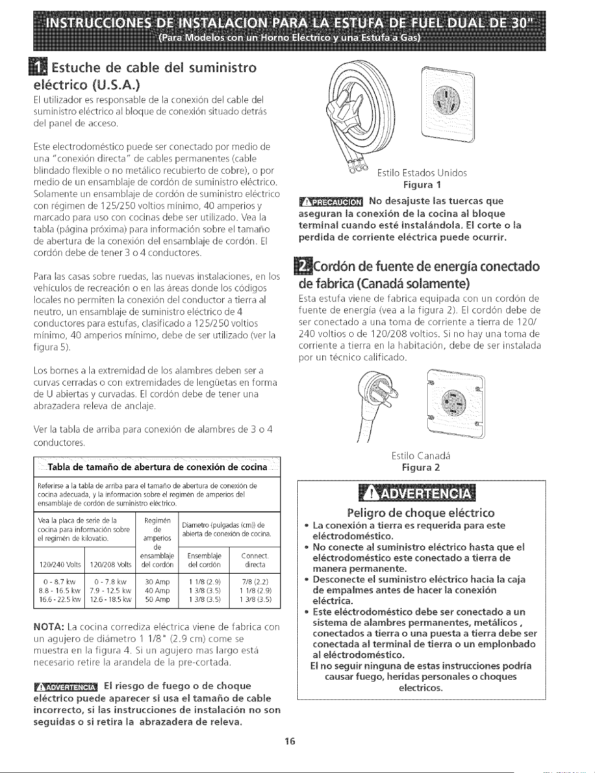
Estilo Estados Unidos
Figura 1
No desajuste las tuercas que
aseguran ta conexiOn de ta codna at bloque
terminat cuando est_ instal_ndola. El corte o ta
perdida de corriente el_ctrica puede ocurrir.
de fuente de energia conectado
de fabrica (Canad8 solamente)
Esta estufa viene de fabrica equipada con un (:ord(m de
fuente de energla (vea a la figura 2). El cordc_n debe de
set conectado a una toma de corriente a tierra de 120/
240 voltios o de 120/208 voltios. Si no hay una toma de
corriente a tierra en la habitaciOn, debe de set instalada
pot un tecnico calificado.
Ver la tabla de arriba para conexion de alambres de 3 o 4
conductores.
Tabla de tamafio de abertura de conexion de cocina
Referirsea la tabla de arriba para el tamaho de abertura de conexiOnde
cocina adecuada, y la informaci0n sobre el regimen de amperios del
ensamblaje de cordon de suministro electrico.
Vea la placa de serie de la
cocina para informaci0n sobre
el regimen de kilovatio.
Regimen
de
amperios
de
ensamblaje
del cordon
Diametro(pulgadas(cm))de
abiertade conexiOnde cocina.
Ensemblaje Connect.
120/240 Volts 120/208 Volts del cordon directa
0 - 8.7 kw 0 - 7.8 kw 30 Amp 1 1/8 (2.9) 7/8 (2.2)
8.8- 16.5 kw 7.9 - 12.5 kw 40Amp 1 3/8 (3.5) 1 1/8 (2.9)
16.6-22.5kw 12.6-18.5kw 50Amp 13/8(3.5) 13/8(3.5)
NOTA: La cocina corrediza electrica viene de fabrica con
un agujero de diametro 1 I/8" (2.9 cm) come se
muestra en la figura 4. Si un agujero mas largo esta
necesario retire la arandela de la pre-cortada.
_!_ E! riesgo de fuego o de choque
e!_ctrico puede aparecer si usa el tama_o de cable
incorrecto, si tas instrucciones de instataci6n no son
seguidas o si retira ta abrazadera de reteva.
Estilo Canada
Figura 2
Peligro de choque el_ctrico
• La conexiOn a tierra es requerida para este
e[_ctrodom_stico.
• No conecte al suministro el_ctrico hasta que et
el_ctrodom_stico este conectado a tierra de
manera permanente.
• Desconecte e! suministro el_ctrico hacia [a caja
de empalmes antes de hacer [a conexiOn
el_ctrica.
• Este el_ctrodom_stico debe set conectado a un
sistema de alambres permanentes, met_licos,
conectados a tierra o una puesta a tierra debe set
conectada aJ terminal de tierra o un emplonbado
al eJ_ctrodom_stico.
EJno seguir ninguna de estas instrucciones podr_a
causar fuego, heridas personales o choques
electricoso
16
Cone×ion EN ctrico de [a Estufa
(U.S.A.}
Este aparato se fabrica con el terminal neutro conectado
a! marco.
Refiere al diagrama de alambraje en las paginas de
centro de este manual.
Conexion de tres alambres de conduccibn a
la estufa
(Un cordon flexible o cable de 3 conductores debe de ser
reemplazado con un cordon flexible o cable de 4 conducto-
res donde la conexiOn del conductor a tierra al neutro esta
prohibida en las nuevas instalaciones, las casas sobre
ruedas, los vehlculos de recreation o otras areas donde los
codigos locales no permiten la conexiOn a tierra al neutro.)
Si los c0digos locales permiten la conexi0n del conductor
de tierra del marco con el alambre neutro de! cordon
electrico de cobre (vea Figura 4):
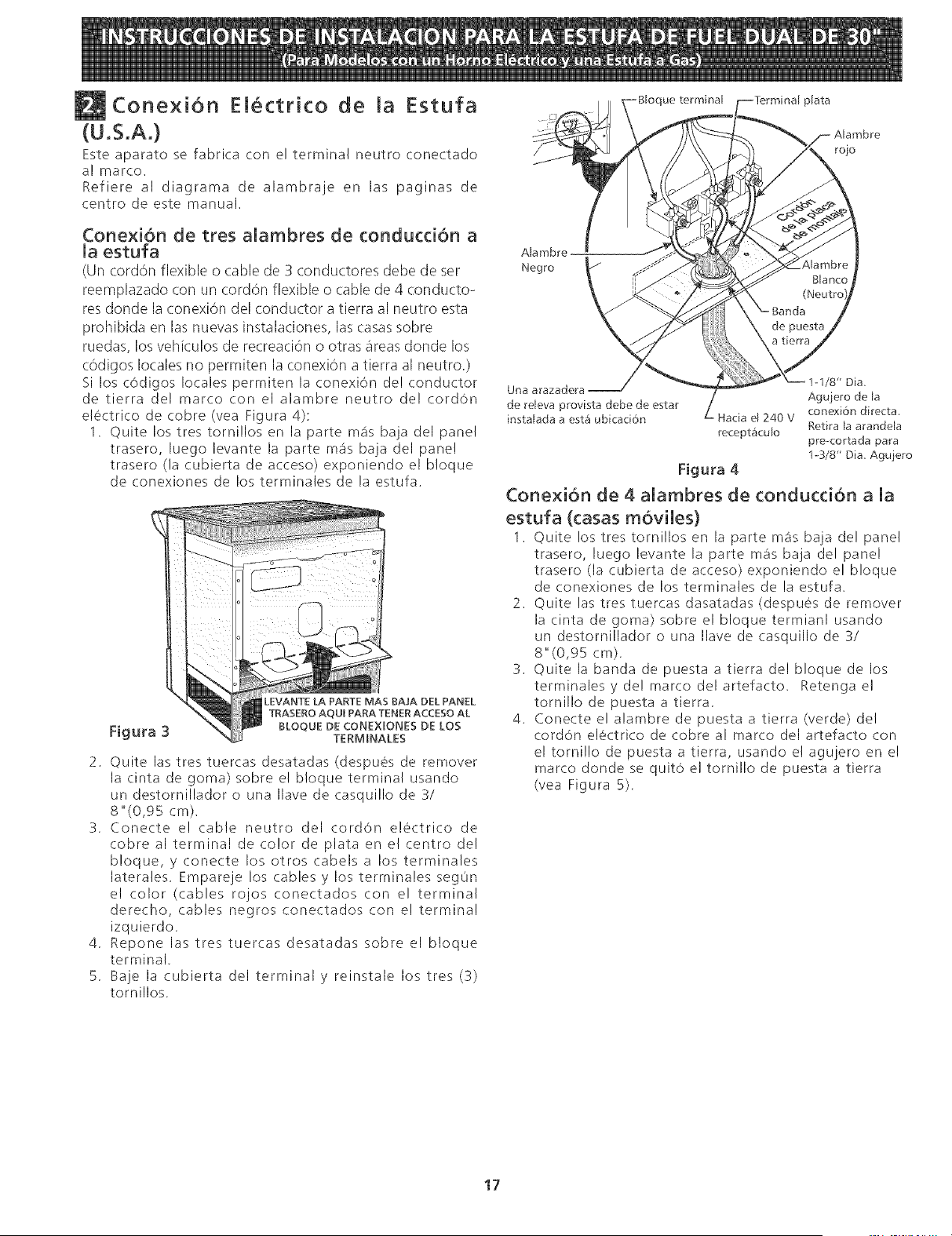
1. Quite los tres torni!los en la parte ma_sbaja del panel
trasero, luego levante la parte m_is baja del panel
trasero (la cubierta de acceso) exponiendo el bloque
de conexiones de los terminales de la estufa.
F[gura 3
LEVANTE LA PARTE MAS BAJA DEL PANEL
TRASERO AQU[ PARA TENER ACCESO AL
BLOQUE DE CONEXEONES DE LOS
TERMENALES
2. Quite las tres tuercas desatadas (despues de remover
la cinta de goma) sobre e! b!oque terminal usando
un destornillador o una Ilave de casqui!lo de 3/
8"(0,95 cm).
3. Conecte e! cable neutro del cordon e!#ctrico de
cobre al terminal de color de plata en e! centro de!
b!oque, y conecte los otros cabels a los terminales
laterales, Empareje los cables y los terminales segOn
e! color (cables rojos conectados con el terminal
derecho, cables negros conectados con el terminal
izquierdo,
4. Repone las tres tuercas desatadas sobre el b!oque
terminal,
5. Baje la cubierta del terminal y reinstale los tres (3)
tornillos.
ue terminal plata
Alambre
Negro
Una arazadera
de rdeva provista debe de estar
instalada a est_ ubicad6n
/8" Dia.
Aguiero de la
L Hacia el 240 V conexi6n directa.
recept&culo Retira la arandela
pre-cortada para
13/8" Dia. Aguiero
Figura 4
ConexiOn de 4 alambres de conduction a la
estufa (casas moviles}
1. Quite los tres tornillos en la parte m_is baja de! panel
trasero, luego levante la parte m_is baja del panel
trasero (la cubierta de acceso) exponiendo e! bloque
de conexiones de los terminales de la estufa,
2. Quite las tres tuercas dasatadas (despues de remover
la cinta de goma) sobre el bloque termianl usando
un destornillador o una Ilave de casquillo de 3/
8"(0,95 cm),
3. Quite la banda de puesta a tierra del bloque de los
terminalesyde! marco delartefacto, Retengael
tornillo de puesta a tierra,
4. Conecte el alambre de puesta a tierra (verde) del
cordon electrico de cobre al marco del artefacto con
el tornillo de puesta a tierra, usando el agujero en el
marco donde se quit0 el tornillo de puesta a tierra
(vea Figura 5).
17
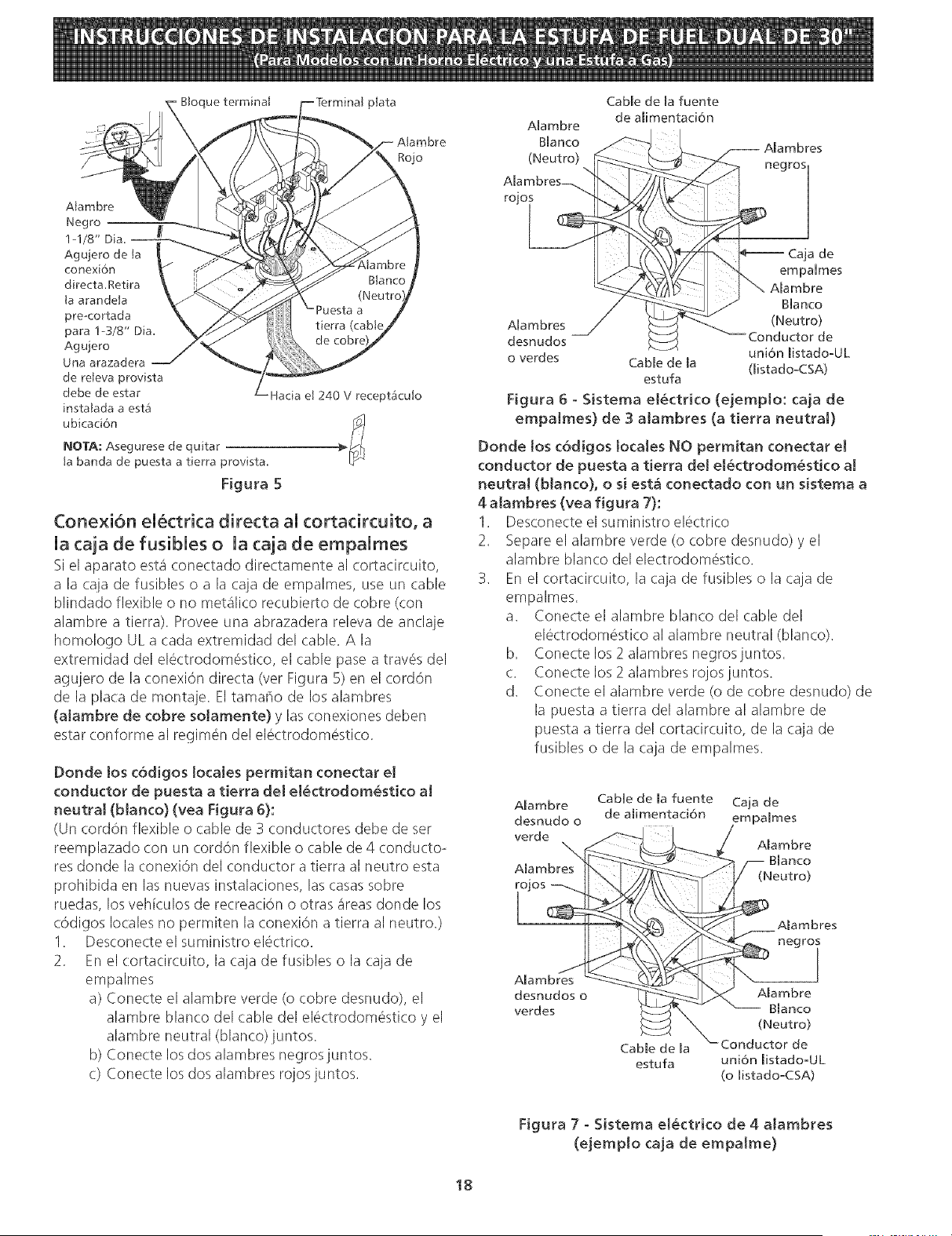
Btoque terminal plata
Rojo
Atambre
Negro _/
1-1/8" Dia.
Agujero de ta
conexi6n
directa.Retira
ta arandeta
pre<ortada
para !-3/8" Dia.
Agujero
Una arazadera
de releva provista
debe de estar
instatada a esta
ubicaci6n
@OTA; Asegurese de quitar
ta banda de puesta a tierra provista.
Figura 5
el 240 V receptacu[o
Conexi6n el_ctrica directa al cortadrcuito, a
la caja de fusibles o la caja de empalmes
Si el aparato esta conectado dire(tamente al (ortacircuito,
a la (aja de fusibles o a la cap de empalmes, use un cable
blindado flexible o no metalico recubierto de cobre (con
alambre a tierra). Provee una abrazadera releva de anclaje
homologo UL a cada extremidad del cable. A la
extremidad del electrodom6stico, el cable pase a trav6s del
agujero de la conexion directa (vet Figura 5) en el (:ord6n
de la pla(a de montaje. El tama¢io de los alambres
(alarnbre de cobre solamente) y las (onexiones deben
estar conforme al regim6n del electrodom(_stico.
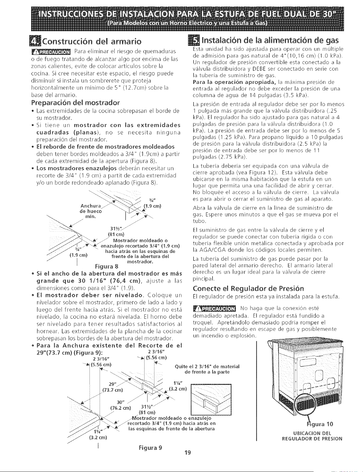
Donde los c6digos locales permitan conectar e!
conductor de puesta a tierra de[ el_ctrodom_stico a[
neutral (blanco) (vea Figura 6):
(Un cordon flexible o cable de 3 conductores debe de ser
reemplazado con un cord6n flexible o cable de 4 conducto-
res donde la conexic_ndel conductor a tierra al neutro esta
prohibida en las nuevas instalaciones, las casas sobre
ruedas, los veh[culos de recreaci6n o otras areas donde los
codigos locales no permiten la conexi6n a tierra al neutro.)
1. Desconecte el suministro electfico.
2. En el cortacircuito, la caja de fusibles o la caja de
empalmes
a) Conecte el alambre verde (o cobre desnudo), el
alambre blanco del cable del electrodom6stico y el
alambre neutral (blanco)juntos.
b) Conecte los dos alambres negros iuntos.
c) Conecte los dos alambres rqos juntos.
Alambre
Blanco
(Neutro)
Alambres_
rojo
Cable de la fuente
de alimentaci6n
Alambres
negros
Caja de
empaimes
_mbre
B[anco
Alambres (Neutro)
desnudos Conductor de
uni6n I[stadooUL
o verdes Cable de la (listadooCSA)
estufa
Figura 6 o Sistema el_ctrico (ejemp[o: caja de
empa[mes) de 3 a[ambres (a tierra neutral)
Donde los c6d[gos locales NO perm[tan conectar el
conductor de puesta a tierra de[ e[_ctrodom_stico a[
neutra[ (bIanco), o si est& conectado con un sistema a
4 aIambres (yea figura 7):
1. Descone(te el suministro electrico
2. Separe el alambre verde (o cobre desnudo) y el
alambre blanco del electrodomestico.
3. En el cortacircuito, la caja de fusibles o la caja de
empalmes.
a. Conecte el alambre blanco del cable del
electrodomestico al alambre neutral (blanco).
b. Conectelos 2 alambres negrosjuntos.
c. Conectelos 2 alambres rojos juntos.
d. Conecte el alambre verde (o de cobre desnudo) de
la puesta a tierra del alambre al alambre de
puesta a tierra del cortacircuito, de la caja de
fusibles o de la caja de empalmes.
Alambre Cable de [a fuente Caja de
desnudo o de alimentaci6n empaimes
verde
Alambre
Alambres
tO Jog
l
(Neutro)
Alambres
negros
Alambres
desnudos o Aiambre
verdes Blanco
(Neutro)
Cable de la de
estufa uni6n [istadomU L
(o listadomCSA)
Figura 7 - Sistema el_ctrico de 4 alambres
(ejemplo caja de empaIme)
18
Construcci6n dem armario
Para eliminar el riesgo de quemaduras
o de fuego tratando de alcanzar algo por encima de las
zonas calientes, evite de colocar articulos sobre la
co(ina. Si cree ne(esitar este espa(io, el riesgo puede
disminuir si instala un sombrerete que proteja
horizontalmente un m[nimo de 5" (!2.7cm) sobre la
base del armario.
Preparad6n de[ mostrador
Las extremidades de la cocina sobrepasan el borde de
su raostrador.
Si tiene un mostrador con [as extremidades
cuadradas (planas), no se necesita ninguna
preparacion del mostrador.
• EJ reborde de frente de mostradores moJdeados
deben tener bordes moldeados a 3/4" (1.9cm) a partir
de cada extremidad de la apertura (Figura 8).
• Los mostradores enazulejos deberan necesitar un
recorte de 3/4" (I .9 (m) a partit de cada extremidad
y/o un borde redondeado aplanado (Figura 8).
Anchura_
de hueco
(1.9 cm)
_:_ 311/2,_ "/
(81 cm)
Mostrador moldeado o
o recortado 3/4" (1.9 ¢m)
hada atr_s en las esquinas de
(1.9 cm) frente de la abertura del
I Figura 8 mostrador.
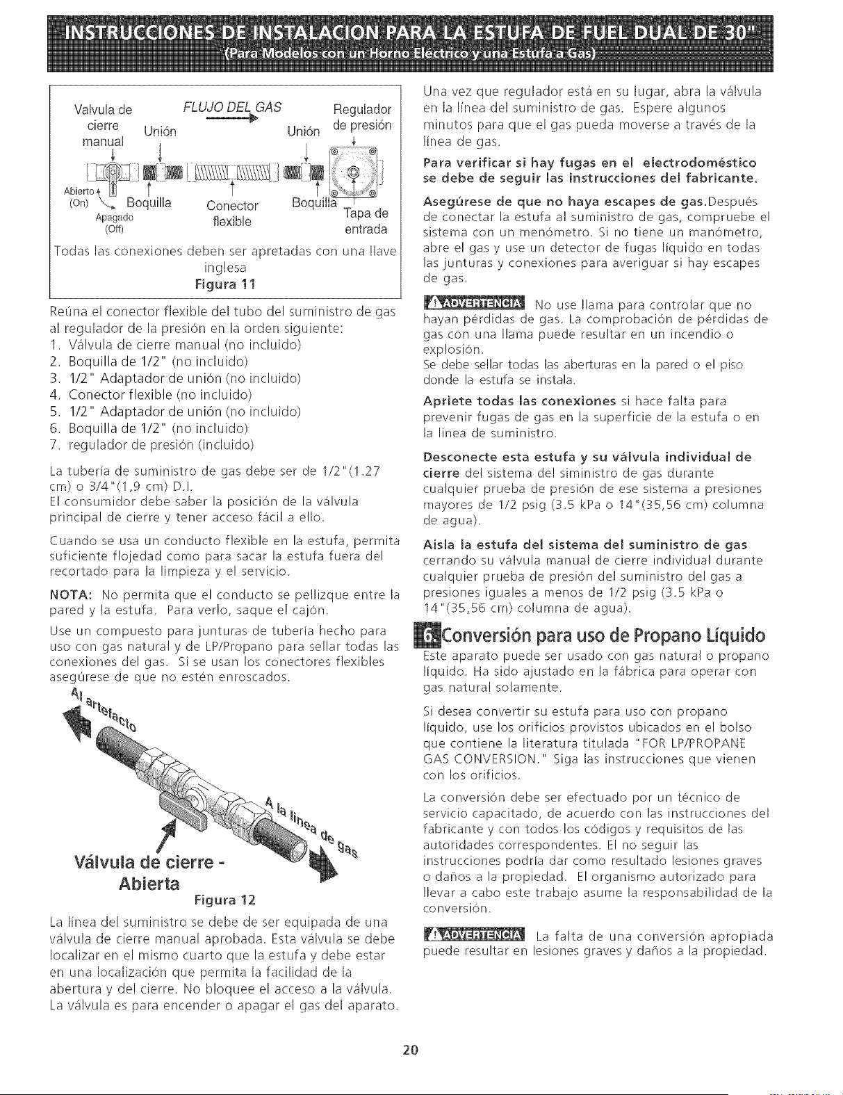
• Si et ancho de Ja abertura deJ mostrador es m_s
grande que 30 1/!6" (76,4 cm}, ajuste a las
dimensiones como para el 3/4" (! .9).
• El mostrador deber set nivelado. Coloque un
nivelador sobre el mostrador, primero de lado a lado y
luego del frente hacia atras. Si el mostrador no estit
nivelado, la cocina no estara nivelada. El homo debe
set nivelado para tenet resultados satisfactorios al
hornear. Las extremidades de la plancha de la cocinar
sobrepasan los bordes de la abertura del mostrador.
• Para la Anchura existente del Recorte de et
29"(73,7 cm) (Figura 9): 2 3/16"
2 3116" (5,56 cm)
, (s.s6cm) i
73.7 cm) _(3.2 cm)
i 30"
(76.2 cm) 31W'/
lnstalaci6n de la alimentaci6n de gas
Esta unidad ha sido ajustada para operar con un m01tiple
de admisiOn para gas natural de 4"(10,16 cm) (1.0 kPa).
Un regulador de presiOn convertible esta conectado a la
wilvula distribuidora y DEBE ser conectado en serie con
la tuber[a de suministro de gas.
Para la operaci6n apropiada, la ma'xima presiOn de
entrada al regulador no debe exceder la presiOn de una
columna de agua de 14 pulgadas (3,5 kPa),
La presi6n de entrada al regulador debe ser por !o menos
1 pulgada mas grande que la valvula distribuidora (.25
kPa), El regulador ha sido ajustado para gas natural a 4
pulgadas de presiOn para la wilvula distribuidora (1,0
kPa), La presiOn de entrada debe ser por Io menos de 5
pulgadas (1,25 kPa), Para propano liquido a 10 pulgadas
de presi6n para la wilvula distribuidora (2.5 kPa) la
presi6n de entrada debe ser pot Io menos de 11
pulgadas (2,75 kPa),
La tuberfa deberia set equipada con una v4lvula de
cierre aprobada(vea Figura 12). Estav4lvula debe
ubicarse en la misma habitaci6n que la estufa en un
lugar que permita una una facilidad de abrir y cerrar,
No bloqueee! acceso a lav4lvula de cierre, Lav4lvula
es para abrir o cerrar el suministro de gas al aparato,
Abra la vatvula de cierre en la linea de suministro de
gas. Espere unos minutos a que el gas se mueva pot el
tubo,
E! suministro de gas entre la wilvula de cierre y el
regulador se puede conectar con tuberia rigida o con
tuberfa flexible uni6n meta'lica conectada y aprobada pot
la AGA/CGA donde los c6digos locales permiten,
La tuberia del suministro de gas puede pasar por la
pared lateral delarmario derecho, Elarmario lateral
derecho es un lugar ideal para la wilvula de cierre
pincipal,
Conecte el Regulador de Presi6n
El regulador de presi6n esta ya instalada para la estufa.
No haga que la conexi6n est@
demadiadoapretada, E! reguladorest_ fundidoa
troque!, Apret4ndo!odemasiado podrfa romper el
regulador resultando en escape de gas y posiblemente
un incendio o exp!osi6n.
Quite el 2 3/16" de material
de frente a [a parte
(81 cm)
ostrador moldeado o enazu[ejo
recortado 3/4" (1.9 ¢m) hada atr_s en
las esquinas de frente de la abertura
Figura 9
19
igura 10
UBICAaON DEL
REGULADOR DE PRESION
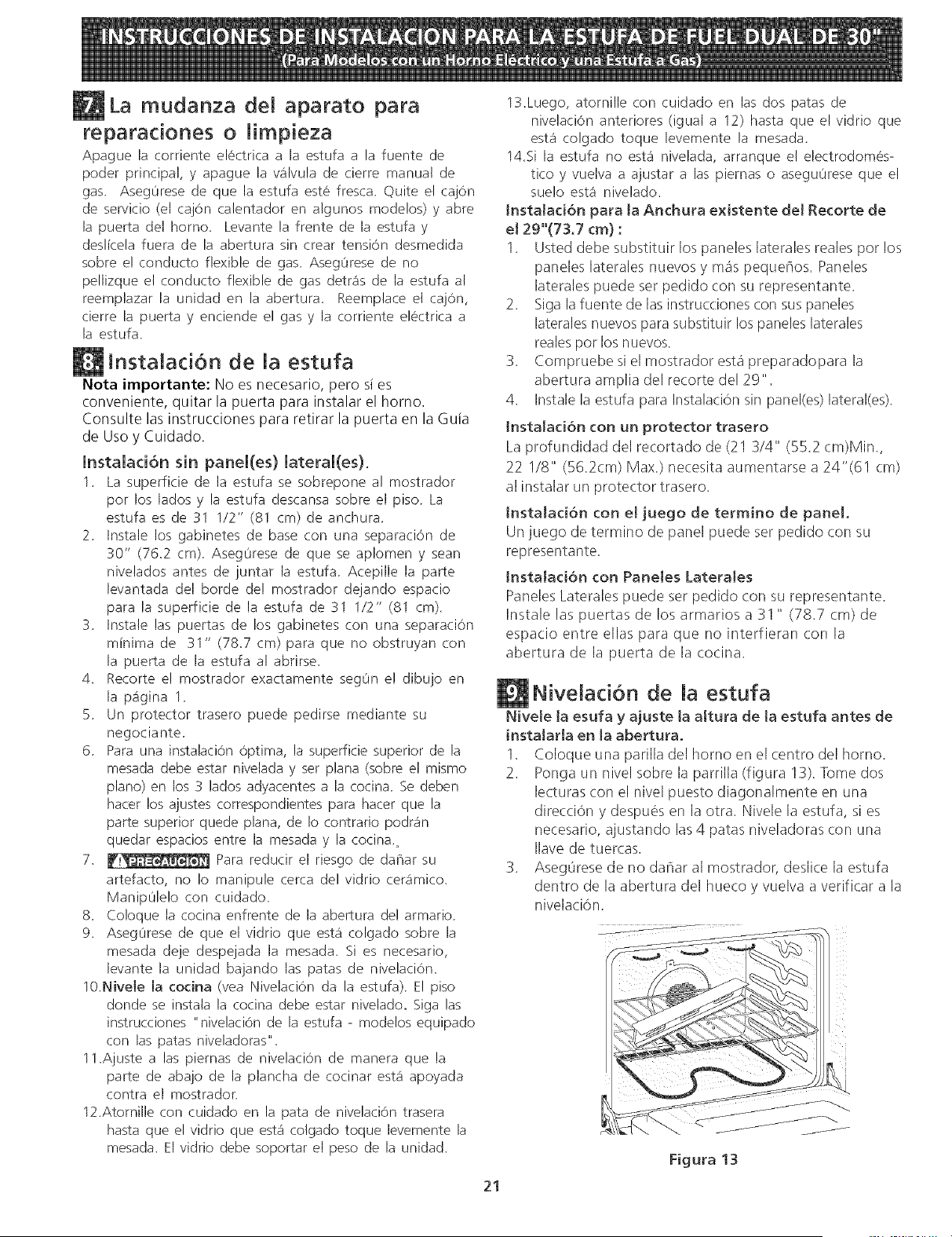
Va!vu!a de FLUJO DEL GAS Regulador
_@ de presi6n
cierre Uni6n Uni6n
manua! ,_
(on) X,_ Boquilla Conector BoquilIa_
Apagado flexible Tapa de
(off) entrada
Todas las conexiones deben ser apretadas con una Ilave
inglesa
Figura 11
ReOna el conector flexible del tubo del suministro de gas
al regulador de la presiOn en la orden siguiente:
1. Valvula de (ierre manual (no incluido)
2. Boquilla de 1/2" (no incluido)
S. 1/2" Adaptador de uni6n (no incluido)
4. Conector flexible (no incluido)
5. 1/2" Adaptador de union (no incluido)
6. Boquilla de 1/2" (no incluido)
7. regulador de presiOn (incluido)
La tuberia de suministro de gas debe ser de 1/2 "(1.27
cm) o 3/4"(1,9 cm) D,I,
El consumidor debe saber la posici6n de la wilvula
principal de cierre y tener acceso f_icil a ello,
Cuando se usa un conducto flexible en la estufa, permita
suficiente flojedad como para sacar la estufa fuera del
recortado para la limpieza y el servicio,
NOTA: No permita quee!conductose pellizqueentre la
pared ylaestufa, Paraverlo, saqueelcajOn,
Use un compuesto para junturas de tuberia hecho para
use con gas natural y de LP/Propano para sellar todas las
conexiones de! gas, Sise usan los conectores flexibles
asegOrese de que no estOn enroscados.
V lvula de cierre -
Abierta
Figura 12
La linea del suministro se debe de ser equipada de una
valvula de cierre manual aprobada. Esta valvula se debe
Iocalizar en el mismo (uarto que la estufa y debe estar
en una IocalizaciOn que permita la facilidad de la
abertura y del cierre. No bloquee el ac.ceso a la v_lvula.
La valvula es para encender o apagar el gas del aparato.
Una vez que regulador esta en su lugar, abra la valvula
enlalineadelsuministrodegas. Esperealgunos
minutos para que el gas pueda moverse a travOs de la
linea de gas.
Para verificar si hay fugas en el electrodomestico
se debe de seguir las instrucdones del fabricante.
Asegurese de que no haya escapes de gas.Despues
de conectar la estufa a! suministro de gas, compruebe el
sistema con un menbmetro. Si no tiene un manOmetro,
abre e! gas y use un detector de fugas liquido en todas
las junturas y conexiones para averiguar si hay escapes
de gas.
No use llama para controlar que no
hayan perdidas de gas, La comprobaciOn de perdidas de
gas con una llama puede resultar en un incendio o
explosi6n,
Se debe sellar todas las aberturas en la pared o el piso
donde la estufa se instala.
Apriete todas las conexiones si hace falta para
prevenir fugas de gas en la superficie de la estufa o en
la linea de suministro,
Desconecte esta estufa y su v_lvula individual de
cierre del sistema de! siministro de gas durante
cualquier prueba de presiOn de ese sistema a presiones
mayores de 1/2 psig (3.5 kPa o 14"(35,56 cm) columna
de agua).
Aisla la estufa del sistema del suministro de gas
cerrando su wilvula manual de cierre individual durante
cualquier prueba de presiOn del suministro del gas a
presiones iguales a menos de 1/2 psig (3.5 kPa o
14"(35,56 cm) columna de agua).
para uso de Propano Liquido
Este aparato puede set usado con gas natural o propano
liquido. Ha sido ajustado en la fa'brica para operar con
gas natural solamente,
Si desea convertir su estufa para uso con propano
liquido, use los orificios provistos ubicados en el bolso
que contiene la literatura titulada "FOR LP/PROPANE
GAS CONVERSION." Siga las instruct!ones que vienen
con los orificios,
La conversion debe ser efectuado por un teen!co de
servicio capacitado, de acuerdo con las instruct!ones del
fabricante y con todos los cOdigos y requisitos de las
autoridades correspondentes, El no seguir las
instruct!ones podria dar como resultado lesiones graves
odaff_osala propiedad, EIorganismoautorizado para
Ilevar a cabo este trabajo asume la responsabilidad de la
conversion.
_!_ La falta de una conversion apropiada
puede resultar en lesiones graves y daf_os a la propiedad.
2O
La mudanza de[ aparato para
reparadones o iimpieza
Apague la corriente electrica a la estufa a la fuente de
poder principal, y apague la v41vula de cierre manual de
gas, Aseg0rese de que la estufa este fresca, Quite el cajOn
de servicio (el cajOn calentador en algunos mode!os) y abre
la puerta del homo, Levante la frente de la estufa y
deslicela fuera de la abertura sin crea_ tension desmedida
sobre e! conducto flexible de gas, Aseg0rese de no
pe!lizque el conducto flexible de gas detr_is de la estufa al
reemplazar la unidad en la abertura, Reemplace el cajOn,
cierre la puerta y enciende el gas y la corriente electrica a
la estufa.
lnstalad6n de la estufa
Nota importante: No es necesario, pero si es
conveniente, quitar la puerta para instalar el horno.
Consulte las instrucciones para retirar la puerta en la Guia
de Uso y Cuidado.
lnstalaci6n sin panel(es) lateral(es).
1. La superficie de la estufa se sobrepone al mostrador
por los lados y la estufa descansa sobre el piso, La
estufa es de 31 1/2" (81 cm) de anchura,
2. Instale los gabinetes de base con una separaciOn de
30" (76,2 cm), Aseg0rese de que se aplomen y sean
nivelados antes de juntar la estufa, Acepille la parte
levantada del borde de! mostrador dejando espacio
para la superficie de la estufa de 31 1/2" (81 cm).
3. Instale las puertas de los gabinetes con una separaciOn
minima de 31" (78,7 cm) para que no obstruyan con
la puerta de la estufa al abrirse,
4. Recorte e! mostrador exactamente segOn el dibujo en
la pa'gina 1,
5. Un protector trasero puede pedirse mediante su
negociante,
6. Para una instalaci6n 6ptima, la superficie superior de la
mesada debe estar nivelada y ser plana (sobre el mismo
piano) en los 3 lados adyacentes a la cocina, Se @ben
hacer los ajustes correspondientes para hacer que la
parte superior quede plana, de Io contrario podr_in
quedar espacios entre la mesada y la cocina,o
7. _ Para reducir el riesgo de daflar su
artefacto, no Io manipule cerca del vidrio cer_imico,
Manip@lelo con cuidado,
8. £o!oque la cocina enfrente de la abertura de! armario,
9. Aseg@rese de que el vidrio que est,1 colgado sobre la
mesada deje despejada la mesada, Si es necesario,
levante la unidad bajando las patas de nivelaci6n.
10.Nivele la codna (vea NivelaciOn da la estufa). E! piso
donde se instala la cocina debe estar nivelado, Siga las
instrucciones "nivelaciOn de la estufa - modelos equipado
con las patas niveladoras",
11.Ajuste alas piernas de nivelaci6n de manera que la
parte de abajo de la plancha de cocinar est,1 apoyada
contra el mostrador,
12.Atornille con cuidado en la pata de nivelaciOn trasera
hasta que el vidrio que esta" colgado toque levemente la
mesada. El vidrio debe soportar el peso de la unidad.
13.Luego, atornille con cuidado en las dos patas de
nivelaci6n anteriores (igual a 12) hasta que el vidrio que
est4 colgado toque levemente la mesada.
14.Si la estufa no est4 nivelada, arranque e! electrodomes-
tico y vuelva a ajustar alas piernas o aseguOreseque el
suelo est4 nivelado.
tnsta[aci6n para ta Anchura existente de[ Recorte de
e[ 29"(73.7 cm) :
1. Usted debe substituir los paneles laterales reales pot los
paneles laterales nuevos y mas pequeFios. Paneles
laterales puede set pedido con su representante.
2. Siga la fuente de las instrucciones (:on sus paneles
laterales nuevos para substituir los paneles laterales
reales pot los nuevos.
3. £ompruebe si el mostrador esta preparadopara la
abertura amplia del recorte de129".
4. Instale la estufa para Instalaci6n sin panel(es) lateral(es).
tnstalaciOn con un protector trasero
La profundidad del recortado de (21 3/4" (55.2 cm)Min.,
22 I/8" (56.2cm) Max.) necesita aumentarse a 24"(61 cm)
al instalar un protector trasero.
tnsta[ad6n con el juego de termino de panel.
Un juego de termino de panel puede ser pedido con su
representante.
tnsta[ad6n con PaneIes LateraJes
Paneles Laterales puede ser pedido con su representante.
Instale las puertas de los armarios a 31 " (78.7 cm) de
espacio entre elias para que no interfieran con la
abertura de la puerta de la cocina.
Niveiad6n de la estufa
Nive[e ta esufa y ajuste [a altura de [a estufa antes de
insta[ar[a en la abertura.
1. £oloque una parilla del homo en el (entro del homo.
2. Ponga un nivel sobre la parrilla (figura 13). Tome dos
lecturas con el nivel puesto diagonalmente en una
direcci6n y despues en la otra. Nivele la estufa, si es
necesario, ajustando las 4 patas niveladoras (.on una
Ilave de tuercas.
3. AsegOrese de no da¢iar al mostrador, desli(e la estufa
dentro de la abertura del hueco y vuelva a verificar a la
nivelaci6n.
21
Figura 13
Comprobacion del
Fundonamiento
Consulte el Manua! del Usuario incluido con la estufa
para instrucciones de operaciOn y instrucciones para el
cuidado y limpieza de su estufa,
No toque Ioselementos o quemadores, Pueden estar
bastante calientes para causar quemaduras,
Quite todo el embalaje de la unidad antes de comprobarla,
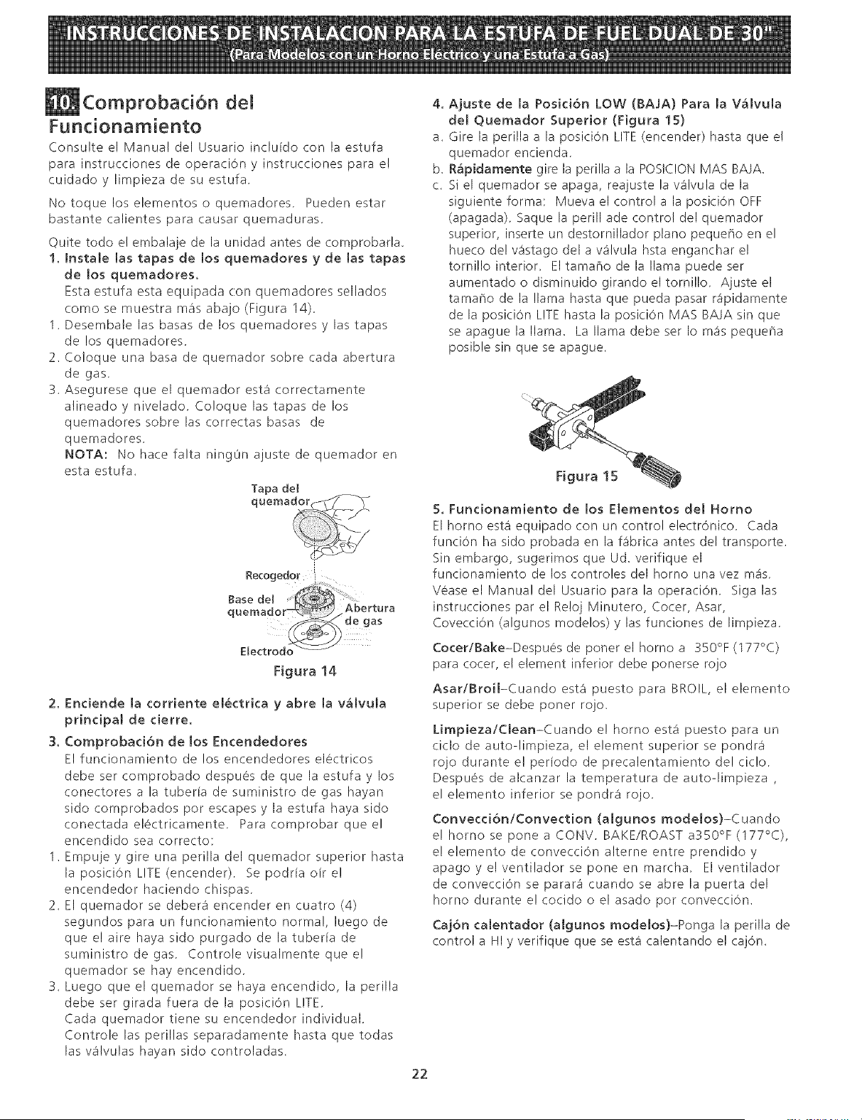
1, Instale [as tapas de los quemadores y de [as tapas
de los quemadores.
Esta estufa esta equipada con quemadores sellados
como se muestra mas abajo (Figura 14).
1. Desembale las basas de los quemadores y las tapas
de !os quemadores,
2. Coloque una basa de quemador sobre cada abertura
de gas,
3. Asegurese que el quemador esta correctamente
alineado y nivelado, Coloque las tapas de los
quemadores sobre las correctas basas de
quemadores,
NOTA: No hate falta ning0n ajuste de quemador en
esta estufa.
Tapa del
Recogedor i
Figura 14
2. Endende [a corriente etectrka y abre [a v_lvula
prff)dpal de derre.
3. Comprobad6n de los Encendedores
El funcionamiento de los encendedores electricos
debe ser comprobado despues de que la estufa y los
conectores a la tuberia de suministro de gas hayan
sido comprobados por escapes y la estufa haya sido
conectada electricamente, Para comprobar que el
encendido sea correcto:
1. Empuje y' gire una perilla del quemador superior hasta
la posiciOn LITE (encender). Se podria oir el
encendedor haciendo chispas,
2. El quemador se debera encender en cuatro (4)
segundos para un funcionamiento normal, luego de
que el aire haya sido purgado de la tuberia de
suministro de gas, Controlevisualmente que el
quemador se hay encendido,
3. Luego que el quemador se haya encendido, la perilla
debe ser girada fuera de la posiciOn LITE,
Cada quemador tiene su encendedor individual,
Controle las perillas separadamente hasta que todas
las wilvulas hayan sido controladas.
4,
a.
b,
C.
Ajuste de la Poski6n LOW (BAJA) Para la V_lvula
del Quemador Superior (Flgura 15)
Gire la perilla a la posici0n LITE (encender) hasta que el
quemador encienda.
R_pidamente gire la perilla a la POSIC!ON MAS BAJA.
Si el quemador se apaga, reajuste la v31vula de la
siguiente forma: Mueva el control a la posiciSn OFF
(apagada). Saque la perill ade control del quemador
superior, inserte un destornillador piano pequeho en el
hueco de! w%tago del a v31vula hsta enganchar e!
tornillo interior. El tamaho de la llama puede ser
aumentado o disminuido girando el tornillo. Ajuste el
tamaf_o de la llama hasta que pueda pasar r_ipidamente
de la posiciOn LITE hasta la posiciOn MAS BAJA sin que
se apague la llama. La llama debeser Io m3spequef_a
posible sin que se apague.
Figura 15
5. Fundonamiento de los Elementos del Homo
El homo esta' equipado con un control electrOnico. Cada
funciOn ha sido probada en la fabrica antes del transporte.
Sin embargo, sugerimos que Ud. verifique el
funcionamiento de los controles del homo una vez m_is.
Vease el Manual del Usuario para la operaci6n. Siga las
instrucciones par el Re!oj Minutero, Cooer, Asar,
CovecciOn (algunos modelos) y las funciones de limpieza.
Cocer/Bake-Despues de poner el homo a 350% (177°C)
para cocer, el element inferior debe ponerse rojo
Asar/Broil-Cuando est3 puesto para BROIL, el elemento
superior se debe poner rojo.
Limpieza/Clean-Cuando e! homo est,1 puesto para un
ciclo de auto-limpieza, el element superior se pondr_i
rojo durante e! perfodo de precalentamiento de! cic!o.
Despues de alcanzar la temperatura de auto-limpieza ,
el elemento inferior se pondr_i rojo.
Convecci6n/Convection (algunos modelos)-Cuando
e! homo se pone a CONV. BAKE/ROAST a350°F (177°C),
e! elemento de convecciOn alterne entre prendido y
apagoyelventiladorse poneen marcha. EIventilador
de convecciOn se parar_i cuando se abre la puerta del
homo durante el cocido o el asado pot convecciOn.
Caj6n calentador (algunos modelos)-Ponga la perilla de
control a HI y verifique que se est,1 calentando el cajOn.
22
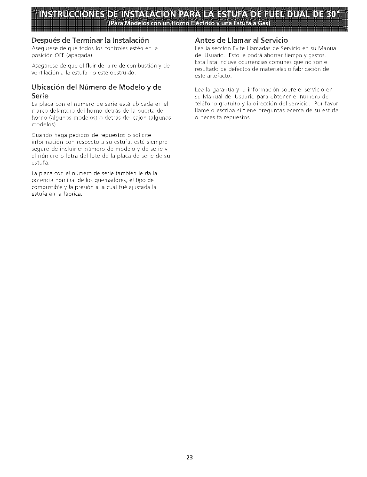
Despu_s de Terminar la Instalad6n
Aseg0rese de que todos los controles esten en la
posiciOn OFF (apagada).
Aseg0rese de que e! fluir de! aire de combustion y de
ventilaciOn a la estufa no est6 obstruido.
Ubicaci6n del NSmero de Modelo y de
Serie
La placa con e! n0mero de serie est_ ubicada en e!
marco delantero del homo detr_is de la puerta del
homo (algunos modelos) o detr_is del caj6n (algunos
modelos).
Cuando haga pedidos de repuestos o solicite
informaci6n con respecto a su estufa, este siempre
seguro de incluir el n0mero de modelo y de serie y
e! n0mero o letra del Iote de la placa de serie de su
estufa,
La plata con e! nt_mero de serie tambien le da la
potencia nominal de los quemadores, e! tipo de
combustible y la presi6n a la cual fue ajustada la
estufa en la fa'brica.
Antes de Llamar al Servicio
Lea la secci6n Evite Llamadas de Servicio en su Manual
del Usuario. Esto le podr_i ahorrar tiempo y gastos.
Esta lista incluye ocurrencias comunes que no son el
resultado de defectos de materiales o fabricaciOn de
este artefacto.
Lea la garantia y la informaciOn sobre e! servlcio en
su Manual de! Usuario para obtener el nOmero de
telefono gratuitoyladirecciOn delservicio, Porfavor
Ilame o escriba si tiene preguntas acerca de su estufa
o necesita repuestos.
23
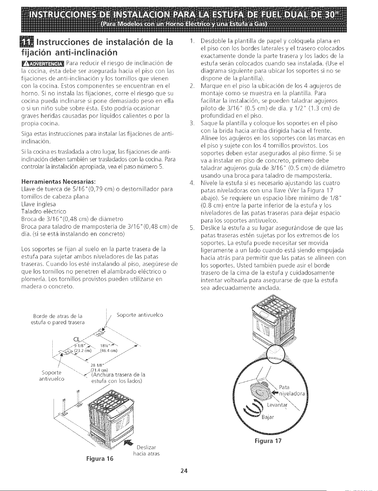
lnstrucdones de instaiad6n de la
fiiadon anti-indinad6n
Para redudr el riesgo de inclinaci6n de
la (ocina, esta debe ser asegurada hacia el piso (.on las
fijadones de anti-inclinaci6n y los tornillos que vienen
con la cocina. Estos componentes se encuentran en el
horno. Si no instala las fijaciones, corre el riesgo que su
cocina pueda inclinarse si pone demasiado peso en ella
o si un nffio sube sobre esta. Esto podr[a ocasionar
graves heridas (.ausadas por I[quidos (.alientes o por la
propia cocina.
Siga estas instrucciones para instalar las fijaciones de anti-
inclination.
Si la (:ocina es trasladada a otto lugar, lasfijaciones de anti-
inclinaci6n deben tambien settrasladados con la cocina. Rata
controlar la instalaci6n apropiada, vea el paso nL_mero5.
Herramientas Necesarias:
Llave de tuer(:a de 5/16"(0,79 cm) o destornillador para
tornillos de (abeza plana
Llave inglesa
Taladro el6ctrico
Broca de 3/16"(0,48 cm) de diametro
Broca para taladro de mamposterla de 3/16"(0,48 cm) de
dla. (si se esta instalando en (.oncreto)
Los soportes se fijan al suelo en la parte trasera de la
estufa para sujetar ambos niveladores de las patas
traseras. Cuando los est6 instalando al piso, asegOrese de
que los tornillos no penetren el alambrado electri(:o o
plomerla. Los tornillos provistos sueden utilizarse en
madera o concreto.
1. Desdoble la plantilla de papel y coloquela plana en
el piso (:on los hordes laterales y el trasero colocados
exactamente donde la parte trasera y los lados de la
estufa seran (:olocados cuando sea instalada. (Use el
diagrama siguiente para ubicar los soportes si no se
dispone de la plantilla).
2. Marque en el piso la ubicacion de los 4 agujeros de
montaje como se muestra en la plantilla. Para
fa(:ilitar la instala(.i6n, se pueden taladrar agujeros
piloto de 3/16" (0.5 (m) de dia. y 1/2" (1.3 cm) de
profundidad en el piso.
3. Saque la plantilla y coloque los soportes en el piso
con la brida hacia arriba dirigida hacia el frente.
Alinee los agujeros en los soportes (on las mar(:as en
el piso y sujete (:on los 4 tornillos provistos. Los
soportes deben estar asegurados al piso firme. Si se
va a instalar en piso de concreto, primero debe
taladrar agujeros guia de 3/16" (0.5 cm) de diametro
usando una broca para taladro de mamposterla.
4. Nivele la estufa si es necesario ajustando las (uatro
patas niveladoras (:on una Ilave (Ver la Figura 17
abajo). Se requiere un espa(io libre minimo de I/8"
(0.8 cm) entre la parte inferior de la estufa y los
niveladores de las patas traseras para dejar espacio
para los soportes antivuelco.
5. Desli(e la estufa a su lugar asegurandose de que las
patas traseras est6n sujetas por los extremos de los
soportes. La estufa puede necesitar ser movida
ligeramente a un lado cuando esta siendo empujada
ha(:ia atras para permitir que las patas se alineen (.on
los soportes. Usted tambien puede asir el horde
trasero de la cima de la estufa y (:uidadosamente
intentar voltearla para asegurarse de que la estufa
sea adecuadamente anclada.
Figura 16
Deslizar
hacia atras
24
Figura 17
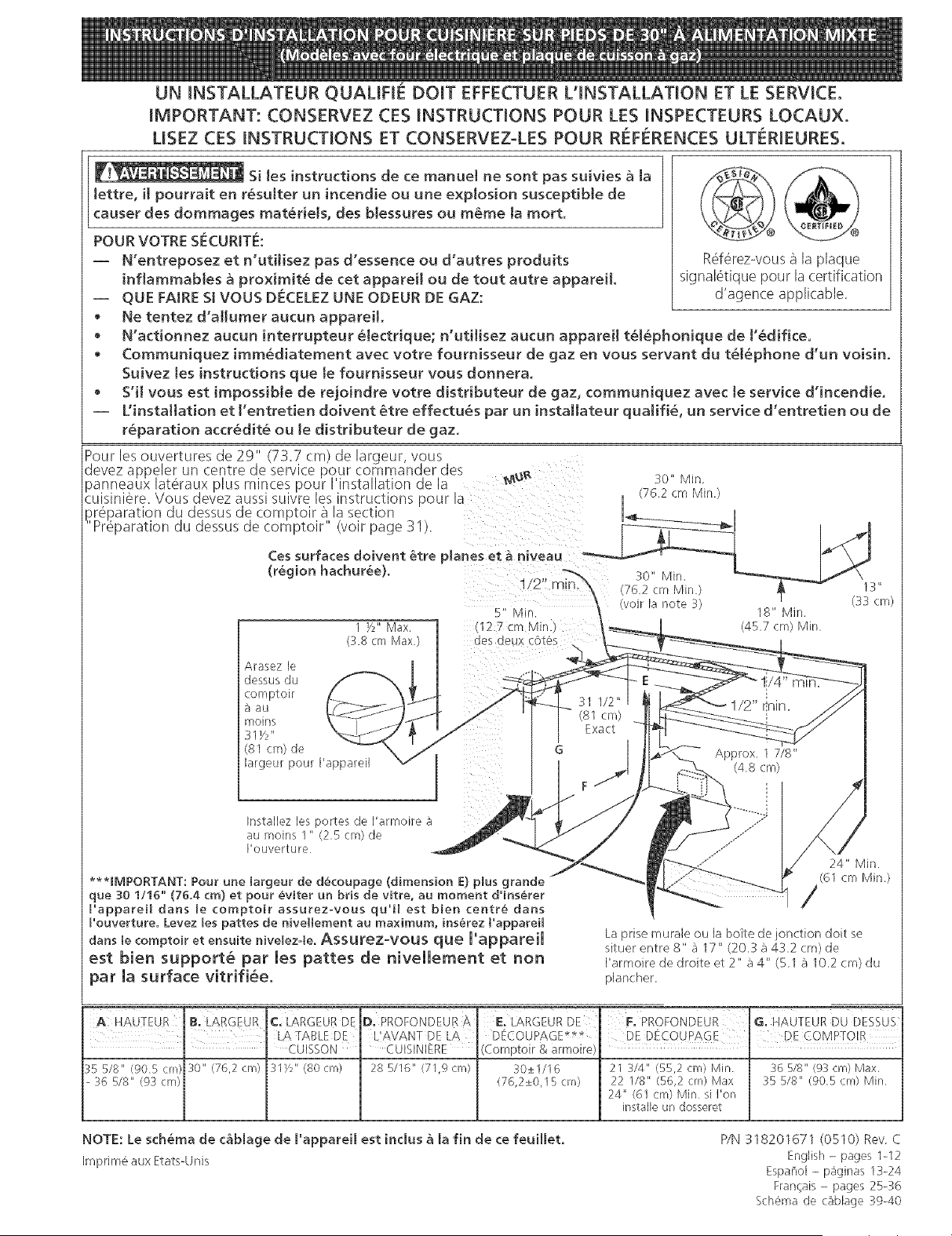
UN INSTALLATEUR QUALIFH_ DOlT EFFECTUER L'INSTALLAT[ON ET LE SERVICE.
IMPORTANT: CONSERVEZ CES INSTRUCTIONS POUR LES INSPECTEURS LOCAUX.
USEZ CES INSTRUCTIONS ET CONSERVEZ-LES POUR REFERENCES ULTERIEURES.
Si Jes instructions de ce manuel ne sont pas suivies _ Ja
tettre, i[ pourrait en r6suJter un incendie ou une expJosion susceptibJe de
causer des dommages mat6deIs, des bIessures ou m6me Jamort.
POUR VOTRE SECURJTE:
-- N'entreposez et n'udHsez pas d'essence ou d'autres produits
inflammables _ proximit6 de cet appareH ou de tout autre appareH.
-- QUE FAIRE SJVOUS DECELEZ UNE ODEUR DE GAZ:
• Ne tentez d'a[[umer aucun appareiL
Rderezwous a la plaque
signal6tique pour la certification
d'agence applicable.
• N'actionnez aucun Jnterrupteur 6[ectHque; n'utJ[isez aucun apparei[ t6[6phonique de t'_difice.
• Communiquez imm6diatement avec votre foumisseur de gaz en vous servant du t6[6phone d'un voisino
Suivez tes instructions que te fournisseur vous donnerao
• S'H vous est irnpossibJe de rejoindre votre distdbuteur de gaz, communiquez avec le service d'incendie.
-- UJnstaJIatJon et ['entretien doJvent 6tre effectu6s par un instaHateur quaJifi6, un service d'entretJen ou de
r_paradon accredit6 ou te d[stHbuteur de gaz.
par ia surface vitrifi6e.
C, LARGEUR DE
LA TABLE DE
l
" CUISSON
:G 5/8" (905cm) 30" (76,2 cm) 31Y2"(80cm)
- 36 518" (93 cm)
D, PROFONDEUR A
L'AVANT DE LA
CUISINIERE
28 5116" (71,9 cm)
j(Comptoir & armoire)
30_+1116
(76,2_+0,15 cm)
F, PROFONDEUR G, HAUTEUR DU DESSU_
DE D_COUPAG E [ DEcorviPTOIR
21 _/4" (55,2 cm) Min 36 5/8" (93 crn) Max,
22 1/8" (56,2 cm) Max 35 5/8" (905 cm) Min
24" (61 crn) Min si I'on
installe un dosseret
NOTE: Le schema de c&blage de I"appareH est indus ,_ la fin de ce feuiJlet,
[mprirne aux Etats-Unis
P/N 318201671 (0510) Rev C
English - pages 1-12
Espanol - p_ginas 13-24
Francais - pages 25-:_6
Sch6ma de c_blage :@-40
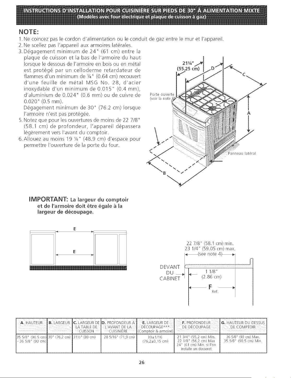
NOTE:
1. Ne coincez pas le cordon d'alimentation ou le conduit de gaz entre le tour et I'appare}l.
2. Ne scellez pas I'appareil aux armoires laterales.
3. Degagement minimum de 24" (61 cm) entre la
plaque de cuisson et la bas de I'armoire du haut
Iorsque le dessous de I'armoire en bois ou en metal
est proteg6 par un celloderme retardateur de
fiammes d'un minimum de X" (0.64 cm) recouvert
d'une feuille de metal MSG No. 28, d'acier
inoxydable d'un minimum de 0.01B" (0.4 mm),
d'aluminium de 0.024" (0.6 ram) ou de cuivre de
0.020" (0.B ram).
Degagement minimum de 30" (76.2 cm) Iorsque
I'armoire n'est pas protegee.
B. Notez que pour les ouvertures de moins de 22 7/8"
(B8.1 cm) de profondeur, I'appareil depassera
legerement vers I'avant du comptoir.
6. AIIouez au moins 19 X" (48.g cm) d'espace pour
permettre I'ouverture de la porte du four.
Porte ouverte
(voir la note
21%"
(55.25 cm
B
A
IMPORTANT: La largeur du comptoir
et de l'armoire doit _tre _gale a la
margeur de d_coupage.
E
E
22 718" (58.1 cm) min.
23 1/4" (59.05 cm) max.
_see note 4)_
DEVANT --_
DU _ _ ,1 1/8"
CABINET _ (2.86 cm)
F
Ref.
A. HAUTEUR B" LARGEUR C. LARGEUR DE
m LA TABLE DE L'AVANT DE LA
" " CUISSON CUISINIERE
:_5 5/8" (905 cm 30" (76,2 crn) 3I/2" (80 cm) 28 5/16" (71,9 crn)
- 36 5/8" (9_ cm)
DE G. HAUTEUR DU DESSUS
DECOUPAGE*£*
(Comptoir & armoire)
30_+1116 21 3/4" (5r_,2 cm) Min. 36 5/8" (93 cm) Max,
(76,2_+0,I5 crn) 22 I/8" (56,2 cm) Max 35 5/8" (90B cm} Min
24" (6I cm) Min sil'on
installe un dosseret
26
Notes importantes 8 ['installateur
1. Lisez toutes [es instructions contenues dans ce feuillet avant
d'installer la cuisiniere.
2. Enlevez tout le materiel d'emballage du four et du tiroir avant
de connecter ['alimentation _ gazet 6[ectrique a [a cuisiniere
3. Respectez tous[es codes et reglements applicables.
4. N'oubliez pas de laisser ces instructions au consommateur.
Note importante au consommateur
Conservez ces instructions avec le guide de I'utilisateur pour
r6f6rence ulterieure_
INSTRUCTIONS DE S[ CURIT[
Cette cuisiniere dolt _tre install_e conform6ment aux
reglements Iocaux, ou en leur absence, aux normes CAN/
ACG-B149 1 et CAN/ACG-B14%2
La conception de cette cuisiniere a 6t6 approuv6e par
['ACNOR internationale II faut prendrecertaines precautions
d'usage lots de ['utilisation de tout apparei[ fonctionnant au
gaz nature[ ou produisant de [a chaleur Vous trouverez
celles-ci dans votre Guide d'utilisateur [isez-les avec
attention.
Assurezivous que votre cuisini_re est correctement
install_e et raise a [a terre par un installateur ou un
technicien d'entretien qualifi_.
Le circuit &lectrique de cette cuisini&re doit _tre mis &
[a terre conform&ment aux r_glements Iocaux, ou en [eur
absence, a [a norme canadienne d'_[ectricit_, ACNOR
C22_1, partie 1
. L'installation d'apparei[s conlus pour [es maisons (mobiles)
doit se conformer aux normes de la Manufactured Home
Construction and Safety Standard, titre 24CFR, partie 3280
(ant_rieurement Federal Standard for Mobile Home
Construction and Safety, titre 24, HUD (pattie 280)) ou en
[eurs absences, aux normes de [a Manufactured Home
Installation 1982 (Manufactured Home Sites, Communities
and Setups), ANSI Z225 1/NFPA 501Aoderniere edition, ou
auxcodes Iocaux LorsqueJ'instalJation se fait au Canada,
eJle dolt se conformer _ [a norme CAN/ACNORoZ240 MH
Assurez-vous que [a tapisserie a proximit_ de [a
cuisini&re peut r_sister & la chaleur g_n_r_e par [a
cuisiniere.
Avant dqnstaller la cuisiniere & un endroit recouvert de
linoleum ou de tout autre couvre-plancher synth_tique,
assurez-vous que celui-d peut r_sister a un minimum de
90°F (32.2°C) de chaleur au-dessus de [a temperature
de la piece sans se rapetisser, se d_former ou se
d_colorer. N'instal[ez pas [a cuisiniere sur un tapis, a moins
]butes [es
cuisinieres peuvent
basculer
Des blessures
pourraient survenir. [
Installer les supports [
anti-bacules qui
accompagnent la
cuisiniere
Pour pr6venir tout risque de
basculement de la cuisiniere,
cet appareil doit 6tre fixe
correctement au plancher
I'aide des supports qui
I'accompagnent Pour verifier
si les supports sont pos_s
correctement, retirer le tiroir
de rangernen_ et s'assurer que
les supports son_endenches.
de placer un tampon isolant ou une feuille de contreplaqu6
d'une 6paisseur de ¼" (0.6 cm) entre [a cuisiniere et le
tapis
Ne bloquez pas la circulation d'air & I'orifice de
ventilation du four ni autour de [a base ou sous [e
panneau inf_rieur avant de [a cuisini_re, Evitez de
toucher [es ouvertures de ['orifice de ventilation ou [es
surfaces avoisinantes car e[[es risquent de devenir chaudes
Iorsque le four fonctionne Les br0[eurs ont besoin d'air
frais pour assurer une bonne combustion.
, o _o .
., _w_,_]4_,_[_[@ Ne laissez jamais les enfants seuls
ou sans surveillance pres d'un appareil en
fonctionnement. Apprenez-leur a utiliser [es appareils
61ectrom6nagers de facon s6curitaire et appropri6e. Ne laissez
jamais la porte du four ouverte [orsque la cuisiniere est sans
surveillance
Le fait de monter sur les portes ou
les tiroirs de cette cuisiniere, de s'y appuyer ou de s'y
asseoir peut occasionner des blessures graves, et
endommager ['appareH.
N'entreposez pas d'objets susceptibles dqnt_resser les
enfants darts [es armoires situ_es auidessus de [a
cuisiniere, Ils risquent de se br_ler serieusement s'ils
tentent de grimper sur I'appareil
I_vitez de placer des armoires de rangement au-dessus
des br_leurs afin d'_liminer [es gestes inutiles auidessus
de ceux-d.
R_glez [a flamme du br_[eur pour qu'elle ne d_passe
pas [e bord de ['ustensHe utHis_ pour [a cuisson. Une
flamme excessive est dangereuse
, N'utilisez pas le four a des fins de rangement. Ceci
genere une situation _ventuel[ement dangereuse
N'utiIisez jamais votre cuisini_re pour r_chauffer ou
chauffer [a piece. L'utilisation prolong_e de la cuisini_re
sans une ventilation adequate peut s'av_rer dangereuse.
• Ne gardez pas de produits combustibles, d'essence et
d'autres produits inflammables a proximit_ de cet
apparei[ ou de tout autre apparei[. I[ pourrait en r_sulter
des explosions ou un incendie.
• Lots d'une panne de courant _lectrique, [es br0[eurs de
surface peuvent _tre a[lumes manue[lement; p[acez une
a[[umette a[lum_e pres de la t_te du br0leur et tournez
lentement [e bouton de commande de surface _ la position
LITE Redoublezde prudencesivousallumez un br0[eur de
surface manuellement
, Replacez toutes [es commandes a [a position arr&t
_off_ apres ['uti[isation d'une fonction programmable
chronometr_e.
POUR LES MOD[=LES MUNIS DU MODE
AUTONETTOYANT:
Enlevez [a lecbefrite, les aliments et [es autres
ustensiles avant [e d_marrage d"un cycle
autonettoyant du four. Essuyez tous[es renversements
excessifs_ Suivez [es instructions pour [e pr_-nettoyage dans
le Guide de I'uti[isateur_
27
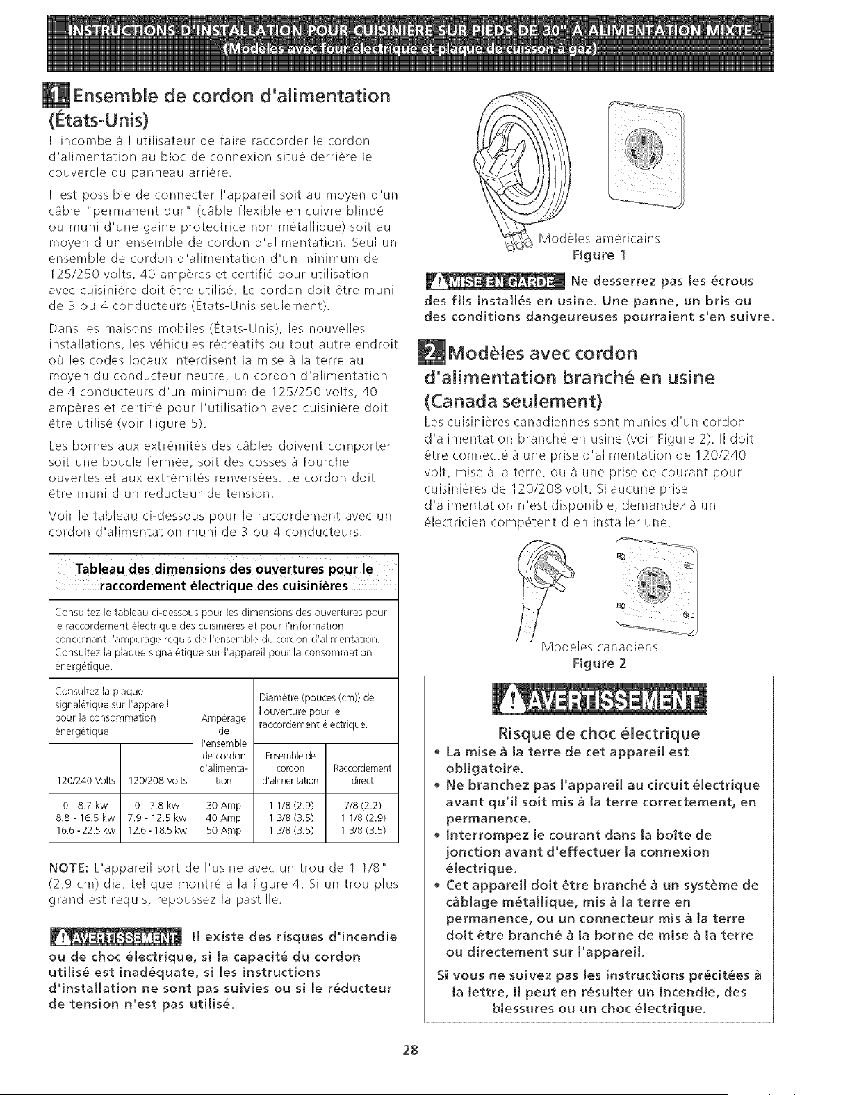
Ensembte de cordon d'alimentation
(Etats-Unis)
II incombe _ !'utilisateur de faire raccorder le cordon
d'alimentation au bloc de connexion situe derriere le
couvercle du panneau arriere,
II est possible de connecter I'appareil soit au moyen d'un
cable "permanent dur" (cAble flexible en cuivre blinde
ou muni d'une gaine protectrice non metallique) soit au
moyen d'un ensemble de cordon d'alimentation, Seul un
ensemble de cordon d'alimentation d'un minimum de
125/250 volts, 40 amperes et certifie pour utilisation
avec cuisiniere dolt 6tre utilise, Le cordon dolt _tre muni
de 3 ou 4 conducteurs (Etats-Unis seulement),
Dans les maisons mobiles (Etats-Unis), les nouve!les
installations, les vehicules recreatifs ou tout autre endroit
oO les codes Iocaux interdisent la mise a la terre au
moyen du conducteur neutre, un cordon d'alimentation
de 4 conducteurs d'un minimum de 125/250 volts, 40
amperes et certifie pour I'utilisation avec cuisiniere dolt
8tre utilise (voir Figure 5).
Les bornes aux extremites des cables doivent comporter
soit une boucle fermee, soit des cosses _3fourche
ouvertes et aux extremites renversees, Le cordon dolt
6tre muni d'un reducteur de tension.
Voir le tableau ci-dessous pour le raccordement avec un
cordon d'alimentation muni de 3 ou 4 conducteurs.
Modeles americains
Figure !
Ne desserrez pas les ecrous
des fils installes en usine. Une panne, un bris ou
des conditions dangeureuses pourraient s'en suivre.
Modeles avec cordon
d'alimentation branch en usine
(Canada seulement)
Les cuisinieres canadiennes sont munies d'un cordon
d'alimentation branche en usine (volt Figure 2). II dolt
_tre (onnecte a une prise d'alimentation de 120/240
volt, mise a la terre, ou a une prise de (ourant pour
cuisinieres de 120/208 volt. Si aucune prise
d'alimentation n'est disponible, demandez a un
electricien comp6tent d'en installer une.
raccordement electrique des cuisinieres
(onsultez le tableau ci-dessous pour les dimensions des ouvertures pour
[e raccordement _lectrique des cuisini_res et pour I'information
concemant I'amperage requis de I'ensemble de cordon d'alimentation.
(onsultez [a plaque signal_tique sur ['appareil pour [a consommation
energetique.
Consultez la plaque
signaletique sur I'appareil
pour la consommation
energetique
120/240 Volts 120/208 Volts
0- 8.7 kw 0- 7.8 kw 30 Amp
8.8 - 16.5 kw 7.9- 12.5 kw 40Amp
16.6 - 22.5 kw 12.6- 18.5 kw 50Amp
Amperage
de
I'ensemble
de cordon
d'alimenta-
tion
Diametre (pouces (cm)) de
I'ouverture pour le
raccordement electrique.
Ensemble de
cordon Raccordement
d'alimentation direct
1 1/8 (2.9) 7/8 (2.2)
1 3/8 (3.5) 1 1/8 (2.9)
1 3/8 (3.5) 1 3/8 (3.5)
NOTE: L'appareil sort de I'usine avec un trou de 1 1/8"
(2.9 cm) dia. tel que montre A la figure 4. Si un trou plus
grand est requis, repoussez la pastille.
I1 existe des risques d'incendie
ou de choc eJectrique, si la capacit_ du cordon
utilise est inadequate, si les instructions
d'installation ne sont pas suivies ou si [e r_ducteur
de tension n'est pas utilise.
Modeles canadiens
Figure 2
Risque de choc 61ectrique
La raise & [a terre de cet apparei[ est
obJigatoire.
• Ne branchez pas ['apparei[ au circuit _[ectrique
avant qu'[[ so[t mis g [a terre correctement, en
permanence,
• tnterrompez le courant darts ta bo_te de
jonction avant d'effectuer [a connexion
_lectrique.
Cet appareil doit 6tre branch_ _ un syst_me de
cSblage m_taHique, mis _ ta terre en
permanence, ou un connecteur mis _ ta terre
doit _tre branch_ _ ta borne de raise _ ta terre
ou directement sur ['appareiL
Si vous ne suivez pas les instructions pr_cit_es
ta tettre, [1 peut en r_su[ter un incendie, des
b[essures ou un choc _[ectrique.
28
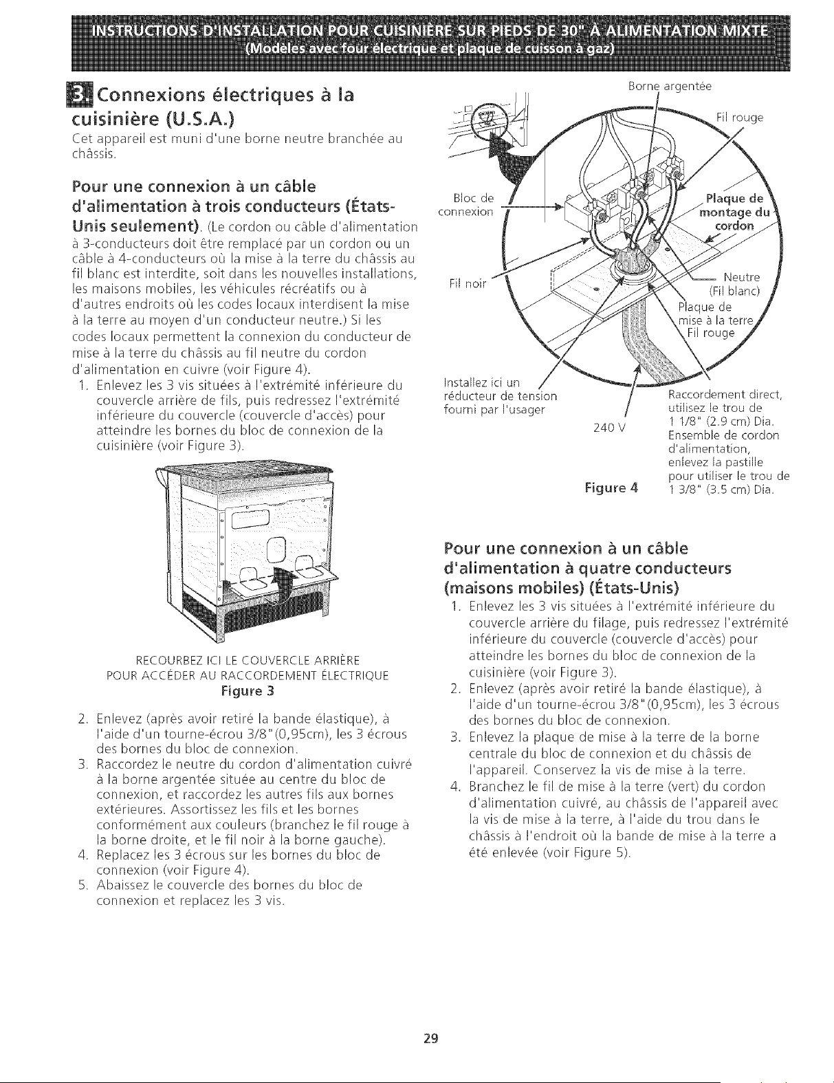
Conne×ions eiectriques a ia
cuisini re (U.S.A.)
Cet appareil est muni d'une borne neutre branchee au
chassis.
Pour une connexion a un cable
d'alimentation a trois conducteurs (fttats o
Unis seulement). (Le cordon ou cable d'alimentation
a 3<onducteurs dolt 6tre remplace par un cordon ou un
(.able a 4-conducteurs oL'Jla raise a la terre du chassis au
fil blanc est interdite, soit dans les nouvelles installations,
les maisons mobiles, les v6hicules re(r6atifs ou a
d'autres endroits oL'Jles codes Iocaux interdisent la mise
a la terre au moyen d'un conducteur neutre.) Si les
codes Iocaux permettent la connexion du conducteur de
raise a la terre du chassis au fil neutre du cordon
d'alimentation en cuivre (voir Figure 4).
1. Enlevez les 3 vis situees a I'extremit6 inferieure du
couvercle arriere de fils, puis redressez I'extremit6
inferieure du couvercle (couver(le d'a(ces) pour
atteindre les bornes du bloc de connexion de la
cuisiniere (voir Figure 3).
Bloc de
connexion
Fil noir
Installez ici un
r_ducteur de tension
fourni par I'usager
Borne argentee
Fil rouge
Raccordement direct,
utilisez le trou de
11/8" (29 cm) Dia
240 V
Ensemble de cordon
d'alimentation,
enlevez la pastille
pour utiJiser Jetrou de
Figure 4 1 3/8" (35 cm) Dia
RECOURBEZ ICI LE COUVERCLE ARRIERE
POUR ACCEDER AU RACCORDEMENT ELECTRIQUE
Figure 3
2. Enlevez (apres avoir retire la bande elastique), a
I'aide d'un tourne-6(rou 3/8"(0,95cm), les 3 ecrous
des homes du bloc de connexion.
3. Raccordez le neutre du cordon d'alimentation cuivre
a la borne argent6e situee au centre du bloc de
connexion, et ra(cordez les autres fils aux homes
ext6rieures. Assortissez les fils et les bornes
conform6ment aux couleurs (branchez le fil rouge a
la borne droite, et le fil noir a la borne gauche).
4. Replacez les 3 6crous sur les bornes du bloc de
connexion (volt Figure 4).
5. Abaissez le couvercle des homes du bloc de
connexion et replacez les 3 vis.
Pour une connexion a un cable
d'alimentation a quatre conducteurs
(maisons mobiles} (tetats°Unis}
1. Enlevez les 3 vis situ6es a I'extremit6 inferieure du
couvercle arriere du filage, puis redressez I'extremit6
inferieure du couvercle (couvercle d'acces) pour
atteindre les bornes du bloc de connexion de la
cuisiniere (voir Figure 3).
2. Enlevez (apres avoir retire la bande (_lastique), a
I'aide d'un tourne-6crou 3/8"(0,95cm), les 3 ecrous
des bornes du bloc de connexion.
3. Enlevez la plaque de raise a la terre de la borne
centrale du bloc de connexion et du chassis de
I'appareil. Conservez la vis de raise a la terre.
4. Branchez le fil de raise a la terre (vert) du cordon
d'alimentation cuivre, au chassis de I'appareil avec
la vis de raise a la terre, a I'aide du trou dans le
chassis a I'endroit oO la bande de raise a la terre a
ete enlev6e (voir Figure 5).
29
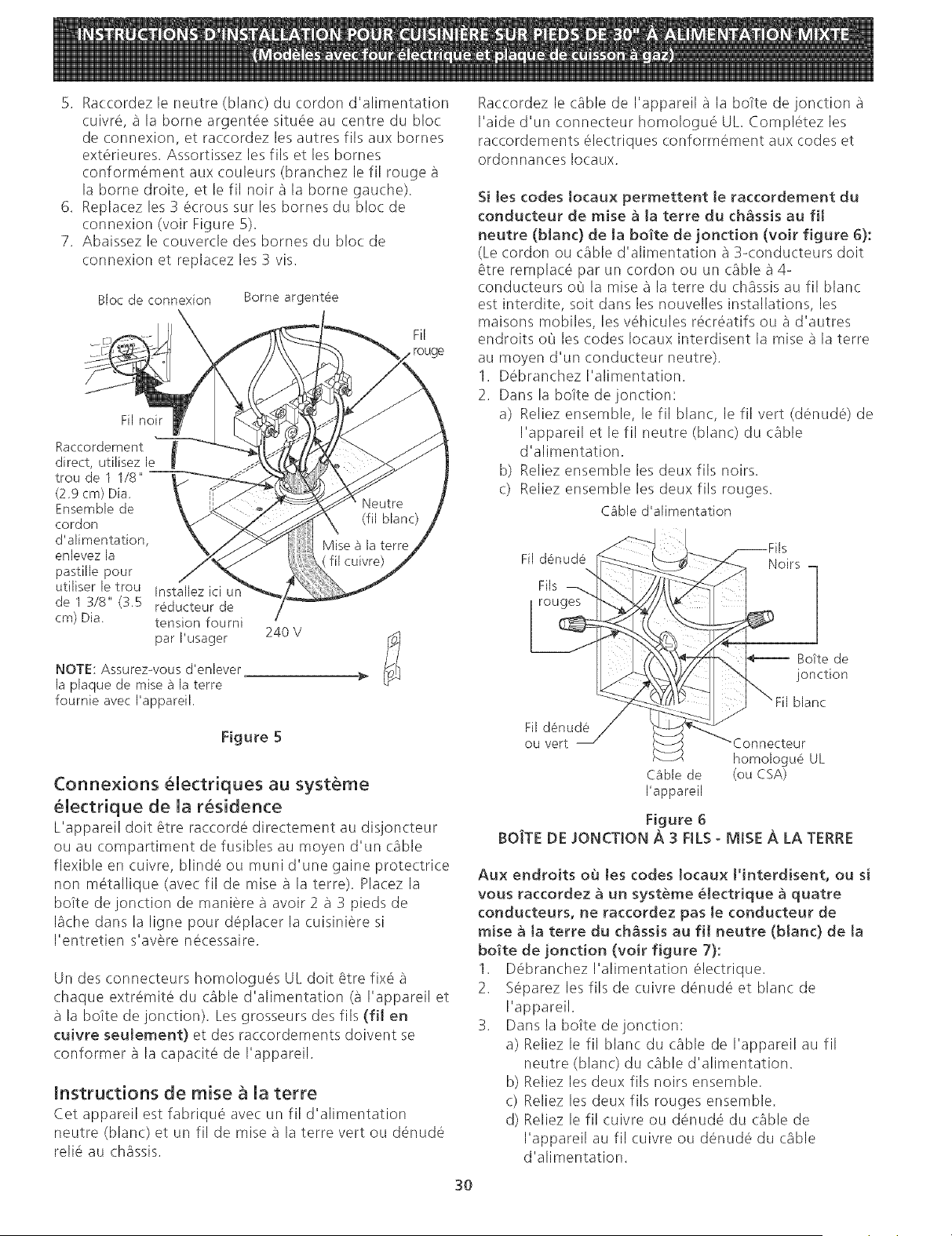
5. Raccordezleneutre(blanc)ducordond'alimentation
cuivre,a laborneargent6esitu6eaucentredu bloc
deconnexion,et raccordezlesautresfib auxbornes
ext@ieures.Assortissezlesfilset lesbornes
conform6mentauxcouleurs(branchezlefil rougea
la bornedroite,etlefil noira labornegauche).
6. Replacezles3 ecroussurlesbornesdublocde
connexion(voltFigure5).
7. Abaissezlecouvercledesbornesdu blocde
connexionet replacezles3 vis.
Bloc de connexion Borne argent@e
Fil
rouge
Fil noir
Raccordement
direct, utilisez le
trou de 1 1/8"
(2.9 cm) Dia
Ensemble de
cordon
d'alimentation,
enlevez la
pastille pour
utiliser le trou
de 1 318" (3.5
cm) Dia
Installez ici
r6ducteur de
tension fourni
par I'usager
NOTE: Assurez-vous d'enlever
la plaque de raise a la terre
fournie avec I'appareik
24O V
Figure 5
Connexions _lectriques au syst_me
_lectrique de la r_sidence
L'appareil dolt 6tre raccorde directement au diqoncteur
ou au compartiment de fusibles au moyen d'un cable
flexible en cuivre, blinde ou muni d'une gaine protectrice
non m@allique (ave( fil de raise a la terre). Pla(ez la
bo_te de jonction de maniere a avoir 2 a 3 pieds de
Bche dans la ligne pour deplacer la cuisiniere si
I'entretien s'avere necessaire.
Un des connecteurs homologues UL dolt 6tre fix6 a
chaque extr6mite du cable d'alimentation (a I'appareil et
a la bolte de jonction). Les grosseurs des fils (ill en
muivre seutement} et des raccordements doivent se
conformer a la capacite de I'appareil.
instructions de raise a la terre
Cet appareil est fabrique avec un fil d'alimentation
neutre (blan() et un fil de raise a la terre vert ou d6nud(_
reli_ au chassis.
Raccordez le (:able de I'appareil a la bo_te de jonction a
I'aide d'un connecteur homologu6 UL CompBtez les
raccordements electriques conform(_ment aux codes et
ordonnances Iocaux.
Si Jes codes tocaux permettent te raccordement du
conducteur de raise _ ta terre du chSssis au fil
neutre (blanc) de ta bo_te de jonction (voir figure 6):
(Le cordon ou c_ble d'alimentation a 3-conducteurs dolt
_tre remplac(_ par un cordon ou un (_ble a 4-
conducteurs o@la raise a la terre du (h_ssis au fil blanc
est interdite, soit dans les nouvelles installations, les
maisons mobiles, les vehicules recr6atifs ou a d'autres
endroits o@les codes Iocaux interdisent la raise a la terre
au moyen d'un conducteur neutre).
1. Debranchez I'alimentation.
2. Dans la boite de jonction:
a) Reliez ensemble, le fil blanc, le fil vert (denud@ de
I'appareil et le fil neutre (blanc) du (.able
d'alimentation.
b) Reliez ensemble les deux fils noirs.
c) Reliez ensemble les deux fib rouges.
Cable d'alimentation
3O
Fil d6nud6
\
Fib
Noirs
Botte de
jonction
blanc
Fil denude
ou vert
Cable de
I'appareil
homologue UL
(ou CSA)
Figure 6
BOJTE DE JONCTION ,&.3 FILS - MISE A LA TERRE
Aux endroits o_ tes codes Iocaux t'interdisent, ou si
vous raccordez 8 un syst_me _lectrique _ quatre
conducteurs, ne raccordez pas [e conducteur de
mise g ta terre du chassis au fi[ neutre (blanc) de ta
bo_te de jonction (voir figure 7):
1. D6branchez I'alimentation electrique,
2. Separez les fils de cuivre d6nude et blanc de
I'appareil.
3. Dans la bo_te de jonction:
a) Reliez le fil blanc du cable de I'appareil au fil
neutre (blanc) du cable d'alimentation.
b) Reliez les deux fils noirs ensemble,
c) Reliez les deux fils rouges ensemble,
d) Reliez le fil cuivre ou denude du c_ble de
I'appareil au fil cuivre ou denude du cable
d'alimentation.
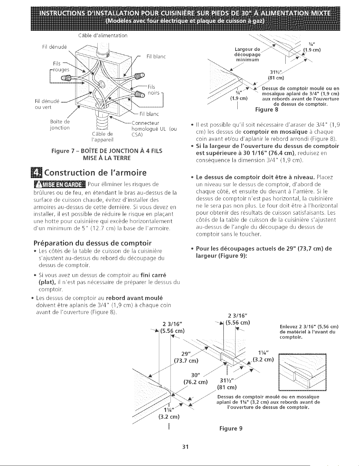
Fi[ d6nud6
rouges
CBbie d'alimentation
Fil blanc
Fil
ou vert
blanc
Bo?te de Connecteur
jonction homologu6 UL (ou
C_ble de CSA)
I'appareil
Figure 7 - BOJTE DE JONCTtON A 4 FILS
MISE A LA TERRE
(1.9 cm)
i
(1.9cm)
/
/
(81cm)
/
de comptoir moul_ ou en
mosa'_'que aplani de 3/4" (1,9 cm)
aux rebords avant de Pouverture
de dessus de comptoir.
Figure 8
II est possible qu'il soit n6cessaire d'araser de 3/4" (1,9
cm) les dessus de comptoir en mosa'l'que a chaque
coin avant et/ou d'aplanir le rebord arrondi (Figure 8).
• Si ta [argeur de ['ouverture du dessus de comptoir
est sup@rieure _ 30 1/16'" (76.4 cm), reduisez en
consequence la dimension 3/4" (I,9 cm).
Construction de l'armoire
Pour @miner les risques de
brOlures ou de feu, en etendant le bras au-dessus de la
surface de cuisson chaude, evitez d'installer des
armoires au-dessus de cette derniere. Si vous devez en
installer, il est possible de reduire le risque en placant
une hotte pour cuisiniere qui excede horizontalement
d'un minimum de 5"' (12.7 cm) la base de I'armoire.
Preparation du dessus de comptoir
Les c6tes de la table de cuisson de la cuisiniere
s'ajustent au-dessus du rebord du decoupage du
dessus de comptoir.
Si vous avez un dessus de comptoir au fini carr_
(plat}, il n'est pas necessaire de preparer le dessus du
comptoir.
Les dessus de comptoir au rebord avant mou!_
doivent 6tre aplanis de 3/4" (!,9 cm) a chaque coin
avant de I'ouverture (Figure 8).
(3.2 cm)
i
Le dessus de comptoir doit @tre g niveau, Placez
un niveau sur le dessus de comptoir, d'abord de
chaque c6t6, et ensuite du devant a I'arriere. Si le
dessus de comptoir n'est pas horizontal, la cuisiniere
ne le sera pas non plus. Le four dolt _tre a I'horizontal
pour obtenir des resultats de cuisson satisfaisants. Les
c6t6s de la table de cuisson de la cuisiniere s'ajustent
au-dessus de I'angle du decoupage du dessus de
comptoir sans le toucher.
Pour [es d_coupages actueJs de 29" (73,7 cm} de
[argeur (Figure 9}:
2 3/16"
(5.56 cm)
Enlevez 2 3/16"" (5,56 cm)
de mat@ie[ a ['avant du
comptoir.
.(3.2 cm)
311/2"/
(81 cm)
/
Dessus de comptoir moul_ ou en mosa'_"que
aplani de 1_/4" (3,2 cm) aux rebords avant de
l"ouverture de dessus de comptoir.
Figure 9
31
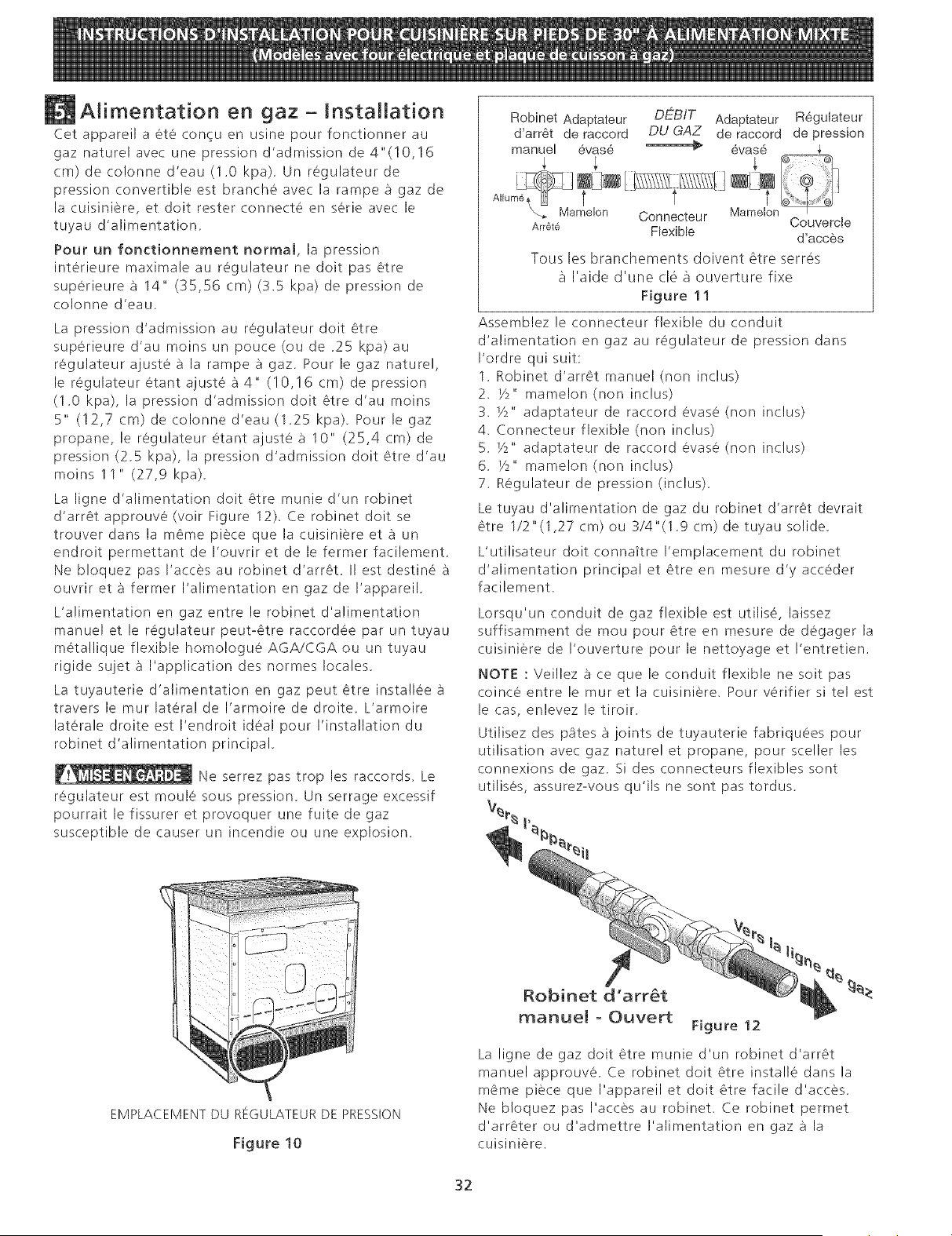
Alimentation en gaz - Installation
Cet appareil a ete con_u en usine pour fonctionner au
gaz naturel avec une pression d'admission de 4"(10,16
cm) de co!onne d'eau (1.0 kpa). Un regulateur de
pression convertible est branche avec la rampe _ gaz de
la cuisiniere, et dolt rester connect6 en serie avec le
tuyau d'alimentation,
Pour un fonctionnement normal, la pression
interieure maximale au regulateur ne dolt pas 6tre
superieure a 14" (35,56 cm) (3.5 kpa) de pression de
colonne d'eau.
La pression d'admission au regulateur dolt Ctre
superieure d'au moins un pouce (ou de 25 kpa) au
regulateur ajuste a la rampe a gaz. Pour le gaz naturel,
le regulateur etant ajuste a 4" (10,!6 cm) de pression
(1,0 kpa), la pression d'admission dolt Ctre d'au moins
5" (12,7 cm) de colonne d'eau (1,25 kpa), Pour le gaz
propane, le regulateur etant ajuste a 10" (25,4 cm) de
pression (2,5 kpa), la pression d'admission dolt Ctre d'au
moins 11 " (27,9 kpa),
La ligne d'alimentation dolt 6tre munie d'un robinet
d'arrCt approuve (voir Figure 12), Ce robinet dolt se
trouver dans la m6me piece que la cuisiniere et _] un
endroit permettant de I'ouvrir et de le fermer facilement,
Ne bloquez pas I'acces au robinet d'arrCt, II est destin6 _]
ouvrir et _] fermer I'alimentation en gaz de I'appareil,
L'alimentation en gaz entre le robinet d'alimentation
manuel et le regulateur peut-¢tre raccordee par un tuyau
metallique flexible homo!ogue AGA/CGA ou un tuyau
rigide sujet _] I'application des normes locales,
La tuyauterie d'alimentation en gaz peut _tre insta!lee _]
travers le mur latera! de I'armoire de droite, L'armoire
laterale droite est I'endroit ideal pour I'installation du
robinet d'alimentation principal,
Ne serrez pas trop les raccords, Le
regulateur est moule sous pression, Un serrage excessif
pourrait le fissurer et provoquer une fuite de gaz
susceptible de causer un incendie ou une explosion.
Robinet Adaptateur DEBIT Adaptateur R6gulateur
d'arr6t de raccord DU GAZ de raccord de pression
manuel 6vas6 _ evas6 ,_
Couvercle
Arr_,te Flexible d'acc_s
Tousles branchements doivent 6tre serres
I'aide d'une (B a ouverture fixe
Figure 11
Assemblez le connecteur flexible du conduit
d'alimentation en gaz au r6gulateur de pression darts
I'ordre qui suit:
1. Robinet d'arrCt manuel (non inclus)
2. P2" mamelon (non inclus)
3. Y2" adaptateur de raccord evase (non inclus)
4. Connecteur flexible (non inclus)
5. _/2" adaptateur de raccord evase (non indus)
6. P2" mame!on (non inclus)
7. Regulateur de pression (inclus).
Le tuyau d'alimentation de gaz du robinet d'arr_t devrait
Ctre 1/2"(1,27 cm) ou 3/4"(1.9 cm) de tuyau solide.
L'utilisateur dolt connaltre I'emplacement du robinet
d'alimentation principal et Ctre en mesure d'y acceder
facilement.
Lorsqu'un conduit de gaz flexible est utilise, laissez
suffisamment de mou pour _tre en mesure de degager la
cuisiniere de I'ouverture pour le nettoyage et I'entretien.
NOTE : Veillez _] ce que le conduit flexible ne soit pas
coince entre le mur et la cuisiniere. Pour v6rifier si tel est
le cas, enlevez le tiroir.
Utilisez des pates _] joints de tuyauterie fabriquees pour
utilisation avec gaz nature! et propane, pour sce!ler les
connexions de gaz. Si des connecteurs flexibles sont
utilises, assurez-vous qu'ils ne sont pas tordus.
EMPLACEMENTDU REGULATEURDE PRESSION
Figure 10
Robinet d'arr_t
manueJ o Ouvert
Figure 12
La ligne de gaz dolt Ctre munie d'un robinet d'arr_t
manuel approuve. Ce robinet dolt Ctre insta!le dans la
mCme piece que I'appareil et dolt Ctre facile d'acces.
Ne bloquez pas I'acces au robinet. Ce robinet permet
d'arr_ter ou d'admettre I'alimentation en gaz _] la
cuisiniere.
32
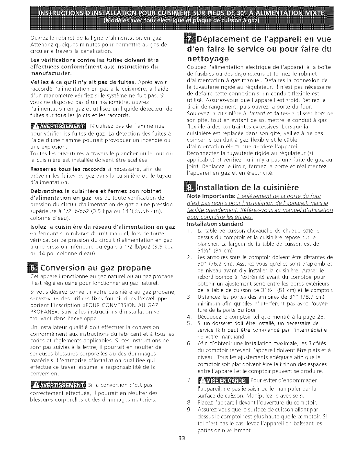
Ouvrez le rob!net de la ligne d'alimentation en gaz.
Attendez quelques minutes pour permettre au gas de
circuler a travers la canal!sat!on,
Les verifkations contre Jes fuites doivent _tre
effectuees conformement aux instructions du
manufacturier.
Veillez a ce quql n'y ait pas de fuites. Apr6s avoir
raccorde I'alimentation en gaz a la cuisiniere, a I'aide
d'un manometre verifiez si le systeme ne fuit pas. Si
vous ne disposez pas d'un manometre, ouvrez
I'alimentation en gaz et utilisez un liquide detecteur de
fuites sur tous les joints et les raccords.
N'utilisez pas de flamme nue
pour verifier les fuites de gaz. La detection des fuites
I'aide d'une flamme pourrait provoquer un incendie ou
une explosion.
Toutes les ouvertures a travers le plancher ou lemur o0
la cuisiniere est installee do!vent 6tre scell6es.
Resserrez tousles raccords si necessaire, afin de
prevenir les fuites de gaz dans la cuisiniere ou le tuyau
d'alimentation.
Debranchez la cuisiniere et ferraez son robinet
d'alimentation en gaz Iors de toute verification de
press!on du circuit d'alimentation de gaz a une press!on
superieure a 1/2 Ib/po2 (3.5 kpa ou 14"(35,56 cm).
colonne d'eau).
IsoJez la cuisiniere du reseau d'aJimentation en gaz
en fermant son robinet d'arr6t manuel, Iors de toute
verification de press!on du circuit d'alimentation en gaz
a une press!on inferieure ou egale a 1/2 Ib/po2 (3.5 kpa
ou 14 po. colonne d'eau)
Conversion au gaz propane
Cet appareil fonctionne au gaz naturel ou au gaz propane.
II est regle en usine pour fonctionner au gaz naturel.
Si vous desirez convertir votre cuisiniere au gaz propane,
servez-vous des orifices fixes fournis dans !'enveloppe
portant I'inscription <<POURCONVERSION AU GAZ
PROPANE>>. Suivez les instructions d'installation se
trouvant dans I'enve!oppe.
Un installateur qualifie dolt effectuer la conversion
conformement aux instructions du fabricant eta tousles
codes et reglements applicables. Si ces instructions ne
sont pas suivies a la lettre, il pourrait en resulter de
serieuses blessures corporelles ou des dommages
materiels. L'entreprise d'insta!lation qualifiee qui
effectue ce travail assume la responsabilit6 de la
conversion.
__ Si la conversion n'est pas
correctement effectuee, il pourrait en resulter des
blessures corporelles et des dommages materiels.
33
D6placement de l'appareil en vue
d'en faire le service ou pour faire du
nettoyage
Coupez I'alimentation electrique de I'appareil _sla boite
de fusibles ou des disjoncteurs et fermez le rob!net
d'alimentation a gaz manuel. Defaites la connexion de
la tuyauterie rig!de au regulateur. II n'est pas n6cessaire
de defaire cette connexion si un conduit flexible est
utilise. Assurez-vous que I'appareil est fro!d. Retirez le
tiroir de rangement, puis ouvrez la porte du four.
Soulevez la cuisiniere a !'avant et faites-la glisser hors de
son gite, tout en evitant de soumettre le conduit a gaz
flexible a des contraintes excessives. Lorsque la
cuisiniere est replacee dans son gite, veillez a ne pas
coincer le conduit a gaz flexible et le cable
d'alimentation electrique derriere I'appareil.
Reconnectez la tuyauterie rig!de au regulateur (si
applicable) et verifiez qu'il n'y a pas une fuite de gaz au
joint. Replacez le tiroir, fermez la porte et r6alimentez
I'apparei! en gaz et en 61ectricite.
Installation de la cuisiniere
Note lmportante: L 'en/evement de/a porte du four
n 'est pas requLs pour/'insta/lation de/'a£2parei/, maLs/a
faci/ite gmndement. R6f6rez-vous au manue/ d'utflLsation
pour conna?tre les 6tapes.
installation standard
1. La table de cuisson chevauche de chaque c6te le
dessus du comptoir et la cuisiniere repose sur le
plancher. La largeur de la table de cuisson est de
31Y2" (81 cm).
2. Les armoires sous le comptoir do!vent 6tre distantes de
30" (76,2 cm). Assurez-vous qu'elles sont d'ap!omb et
de niveau avant d'y installer la cuisiniere. Araser le
rebord bombe a !'extremit6 avant du comptoir pour
obtenir un ajustement serre entre les bords exterieurs
de la table de cuisson de 31_/2'' (81 cm) et le comptoir.
3. Distancez les portes des armoires de 31 " (78,7 cm)
minimum afin qu'elles n'interferent pas avec I'ouver-
ture de la porte du four.
4. Decoupez le comptoir tel que montr6 a la page 28.
5. Si un dosseret dolt 6tre insta!le, un necessaire de
service (kit) peut _tre commande par I'interm6diaire
de votre marchand.
6. Afin d'obtenir une installation max!male, les 3 c6t6s
du (omptoir re(evant I'appareil do!vent 6tre plats et
niveau. Tousles ajustements adequats afin que le
comptoir soit plat do!vent 6tre fait sinon des espa(es
entre I'appareil et le comptoir peuvent se produire.
7. _._l_J_l_J_ Pour eviter d'endommager
I'appareil, ne pas le saisir ou le manipuler par la
surfa(e de cuisson. Manipulezde avec soin.
8. Placez I'appareil devant I'ouverture du comptoir.
9. Assurezwous que la surface de cuisson allant par
dessus le comptoir est plus haute que le comptoir. Si
tel n'est pas le (as, levez I'appareil en baissant les
pattes de nivellement.
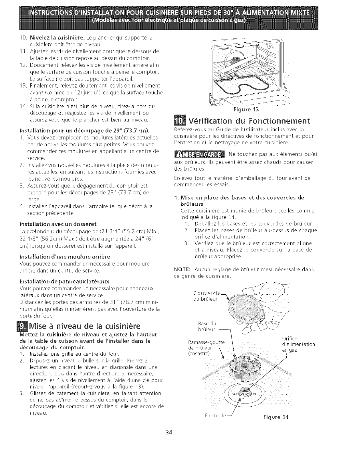
10. NiveJez Ja cuisini@re. Le plancher qui supporte la
cuisiniere dolt 6tre de niveau.
11. Ajustez les vis de nivellement pour que le dessous de
la table de cuisson repose au dessus du comptoir.
12. Doucement relevez les vis de nivellement arriere afin
que le surface de cuisson touche a peine le comptoir.
La surface ne dolt pas supporter I'appareil.
13. Finalement, relevez doucement les vis de nivellement
avant (comme en 12)jusqu'a ce que la surface touche
peine le comptoir.
14. Si la cuisiniere n'est plus de niveau, tirez-la hors du
decoupage et reajustez les vis de nivellement ou
assurez-vous que le plancher est bien au niveau.
Installation pour un decoupage de 29" (73.7 cm).
1. Vous devez remplacer les moulures laterales actuelles
par de nouvelles moulures plus petites. Vous pouvez
commander ces moulures en appellant a un (.entre de
service.
2. Installez vos nouvelles moulures a la place des moulu-
res actuelles, en suivant les instructions fournies avec
les nouvelles moulures.
3. Assurez-vous que le degagement du comptoir est
prepare pour les decoupages de 2g" (73.7 cm) de
large.
4. Installez I'appareil darts I'armoire tel que decrit a la
section precedente.
Installation avec un dosseret
La profondeur du decoupage de (21 3/4" (55.2 cm) Min.,
22 I/8" (56.2cm) Max.) dolt 6tre augmentee a 24"' (61
cm) Iorsqu'un dosseret est installe sur I'appareil.
Installation d'une rnoulure artiste
Vous pouvez commander un n(_cessairepour moulure
arriere darts un centre de service.
Installation de panneaux lat_raux
Vous pouvez commander un necessaire pour panneaux
lateraux darts un centre de service.
Distancez les portes des armoires de 31 " (78.7 cm) mini-
mum afin qu'elles n'interferent pas avec I'ouverture de la
porte du four.
Mise & niveau de la cuisiniere
Mettez la cuisiniere de niveau et ajustez la hauteur
de la table de cuisson avant de I'instaHer darts le
d_coupage du comptoir.
1. Installez une grille au centre du four,
2. Deposez un niveau _] bulle sur la grille. Prenez 2
lectures en plaqant le niveau en diagonale darts une
direction, puis darts I'autre direction. Si necessaire,
ajustez les 4 vis de nivellement a !'aide d'une tie pour
niveler I'appareil (reportez-vous a la figure 13).
3. Glissez delicatement la cuisiniere, en faisant attention
de ne pas ab_mer le dessus du comptoir, darts le
decoupage du comptoir et verifiez si elle est encore de
niveau.
/ j
Figure 13
Verification du Fonctionnement
Referez-vous au Guide de I'utilisateur indus avec la
cuisiniere pour les directives de fonctionnement et pour
I'entretien et le nettoyage de votre cuisiniere.
Ne touchez pas aux elements ou/et
aux brOleurs. IIs peuvent _tre assez chauds pour causer
des brOlures.
Enlevez tout le materiel d'emballage du four avant de
commencer les essais.
1, Mise en place des bases et des couverdes de
br_leurs
Cette cuisiniere est munie de brC]leurs scelles comme
indique a la figure 14.
1. Deballez les bases et les couvercles de brOleur.
2. Placez les bases de brOleur au-dessus de chaque
orifice d'alimentation.
S. Verifiez que le brOleur est correctement aligne
eta niveau. Placez le couvercle sur la base de
brOleur appropriee.
NOTE: Aucun reglage de brOleur n'est necessaire darts
ce genre de cuisiniere.
Couvercle_ /
du braleur
Base du
brOleur
Orifice
Ramasse-gou_e d allmem]a]]on
de _ru_eur \ en gaz
_encas_re
Figure 14
34
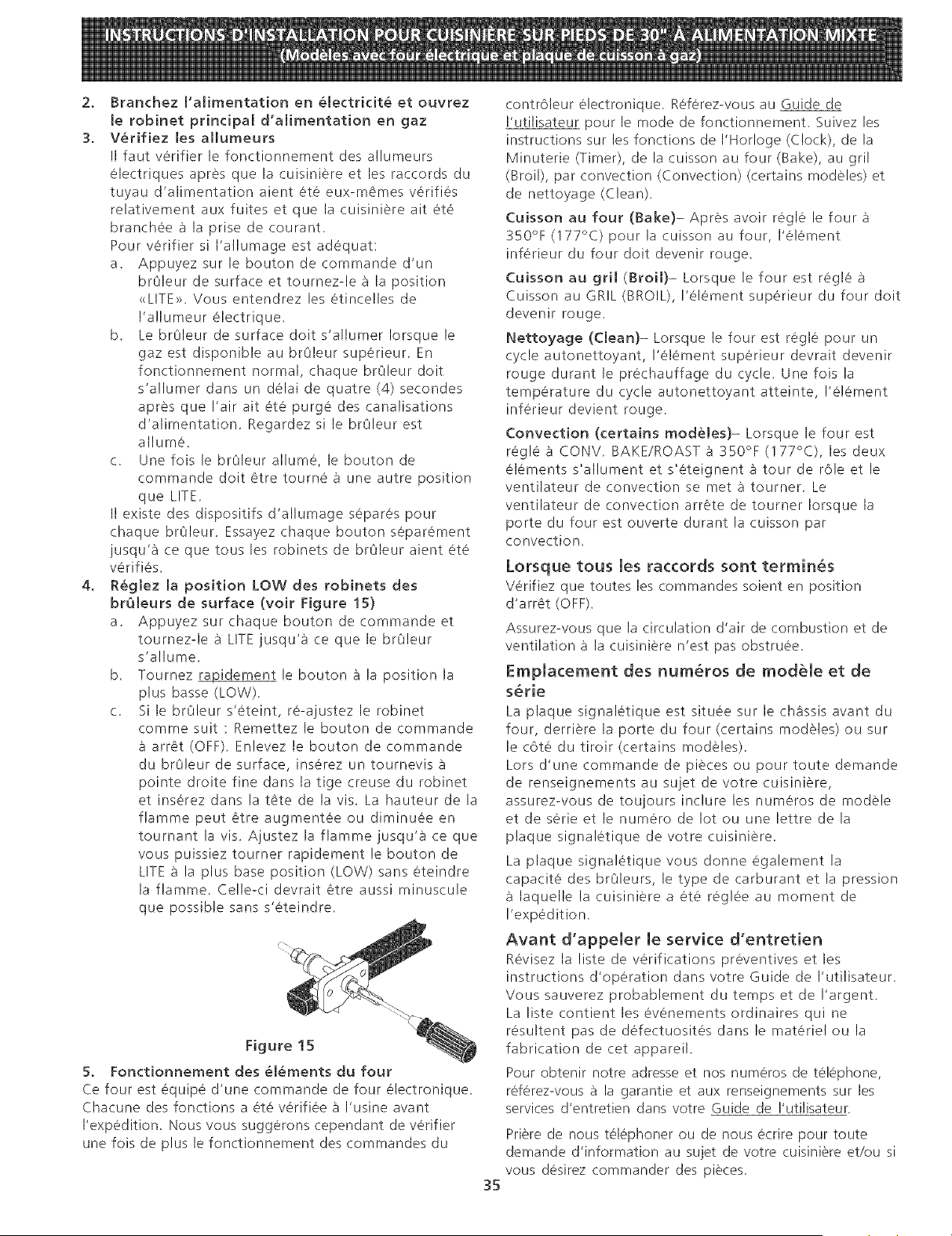
2. Branchez I'alirnentation en electridt_ et ouvrez
le robinet prindpal d'alirnentation en gaz
3. Verifiez les allumeurs
II faut verifier le fonctionnement des a!lumeurs
electriques apres que la cuisiniere et les raccords du
tuyau d'alimentation aient ete eux-memes verifies
relativement aux fuites et que la cuisiniere ait ete
branchee _ la prise de courant.
Pour verifier si I'allumage est adequat:
a. Appuyez sur le bouton de commande d'un
br01eur de surface et tournez-le _ la position
<<LITE>>.Vous entendrez les etince!les de
I'allumeur electrique.
b. Le br01eur de surface dolt s'allumer Iorsque le
gaz est disponible au br01eur superieur. En
fonctionnement normal, chaque br01eur dolt
s'a!lumer darts un delai de quatre (4) secondes
apres que I'air ait ete purge des canalisations
d'alimentation. Regardez si le br01eur est
allume.
c. Une fois le br01eur allume, le bouton de
commande dolt etre tourne _ une autre position
que LITE.
II existe des dispositifs d'allumage separes pour
chaque br01eur. Essayez chaque bouton separement
jusqu'_ ce que tousles robinets de br01eur aient ete
verifies.
4. Reglez la position LOW des robinets des
br_leurs de surface (voir Figure 15)
a. Appuyez sur chaque bouton de commande et
tournez-le _ LITE jusqu'_ ce que le br01eur
s'allume.
b. Tournez _idement le bouton _ la position la
plus basse (LOW).
c. Si le br01eur s'eteint, re-ajustez le robinet
comme suit : Remettez le bouton de commande
arret (OFF). Enlevez le bouton de commande
du br01eur de surface, inserez un tournevis
pointe droite fine darts la tige creuse du robinet
et inserez darts la tete de la vis. La hauteur de la
flamme peut etre augmentee ou diminuee en
tournant la vis. Ajustez la flamme jusqu'a ce que
vous puissiez tourner rapidement le bouton de
LITE a la plus base position (LOW) sans eteindre
la flamme. Celle-ci devrait etre aussi minuscule
que possible sans s'eteindre.
Figure 15
5. Fonctionnement des (_l(_ments du four
Ce four est equipe d'une commande de four electronique.
Chacune des fonctions a ete verifiee _ I'usine avant
I'expedition. Nous vous suggerons cependant de verifier
une fois de plus le fonctionnement des commandes du
contrOleur electronique. Referez-vous au Guide de
I'utilisateur pour le mode de fonctionnement. Suivez les
instructions sur les fonctions de I'Horloge (Clock), de la
Minuterie (Timer), de la cuisson au four (Bake), au gril
(Broil), par convection (Convection) (certains modeles et
de nettoyage (Clean).
Cuisson au four (Bake)- Apres avoir regle le four
350°F (177°C) pour la cuisson au four, I'element
inferieur du four dolt devenir rouge.
Cuisson au gril (Broil)- Lorsque le four est regle ;_
Cuisson au GRIL (BROIL), I'element superieur du four dolt
devenir rouge.
Nettoyage (Clean)- Lorsque le four est regle pour un
cycle autonettoyant, I'element superieur devrait devenir
rouge durant le prechauffage du cycle. Une fois la
temperature du cycle autonettoyant atteinte, I'element
inferieur devient rouge.
Convection (certains modeles)- Lorsque le four est
regle & CONV. BAKE/ROAST _ 350°F (177°C), les deux
elements s'allument et s'eteignent _ tour de role et le
ventilateur de convection se met _ tourner. Le
ventilateur de convection arrete de tourner Iorsque la
porte du four est ouverte durant la cuisson par
convection.
Lorsque tous [es raccords sont terminus
Verifiez que toutes les commandes soient en position
d'arret (OFF).
Assurez-vous que la circulation d'air de combustion et de
ventilation _ la cuisiniere n'est pas obstruee.
Emplacement des num_ros de module et de
s_rie
La plaque signaletique est situee sur le chassis avant du
four, derriere la porte du four (certains modeles) ou sur
le cote du tiroir (certains modeles).
Lors d'une commande de pieces ou pour toute demande
de renseignements au sujet de votre cuisiniere,
assurez-vous de toujours inclure les numeros de modele
et de serie et le numero de lot ou une lettre de la
plaque signaletique de votre cuisiniere.
La plaque signaletique vous donne egalement la
capacite des br01eurs, le type de carburant et la pression
laquelle la cuisiniere a ete reglee au moment de
I'expedition.
Avant d'appeler [e service d'entretien
Revisez la liste de verifications preventives et les
instructions d'operation dans votre Guide de I'utilisateur.
Vous sauverez probablement du temps et de I'argent.
La liste contient les evenements ordinaires qui ne
resultent pas de defectuosites darts le materiel ou la
fabrication de cet appareil.
Pour obtenir notre adresse et nos numeros de telephone,
referez-vous a la garantie et aux renseignements sur les
services d'entretien darts votre Guide de I'utilisateur.
Priere de nous telephoner ou de nous ecrire pour toute
demande d'information au sujet de votre cuisiniere et/ou si
vous desirez commander des pieces.
35
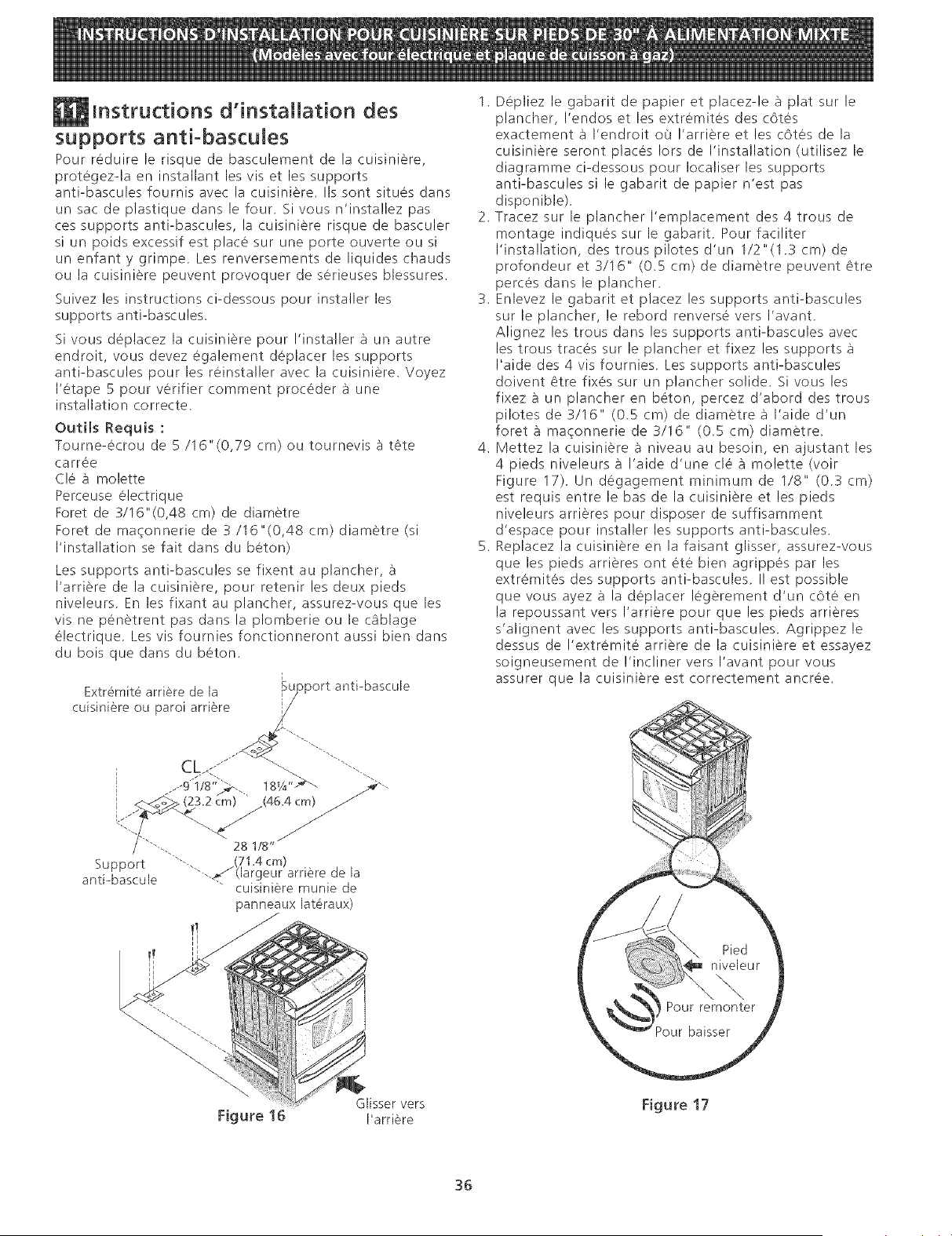
instructions d'installation des
supports anti-bascules
Pour reduire le risque de basculement de la cuisiniere,
protegez-la en installant les vis et les supports
anti-bascules fournis avec la cuisiniere. IIs sont situes darts
un sac de plastique darts le four. 5i vous n'insta!lez pas
ces supports anti-bascules, la cuisiniere risque de basculer
si un poids excessif est place sur une porte ouverte ou si
un enfant y grimpe. Les renversements de liquides chauds
ou la cuisiniere peuvent provoquer de serieuses blessures.
Suivez les instructions ci-dessous pour installer les
supports anti-bascules.
Si vous deplacez la cuisiniere pour I'installer a un autre
endroit, vous devez egalement deplacer les supports
anti-bascules pour les reinstaller avec la cuisiniere. Voyez
I'etape 5 pour verifier comment proceder a une
installation correcte.
OutHs Requis :
Tourne-ecrou de 5/16"(0,79 cm) ou tournevis ;] tCte
carree
Cle ;] molette
Perceuse electrique
Foret de 3/16"(0,48 cm) de diametre
Foret de maqonnerie de 3/16"(0,48 cm) diam6tre (si
I'installation se fait dans du beton)
Les supports anti-bascules se fixent au plancher, ;]
I'arriere de la cuisiniere, pour retenir les deux pieds
niveleurs. En les fixant au plancher, assurez-vous que les
vis ne penetrent pas dans la plomberie ou le c_blage
electrique. Les vis fournies fonctionneront aussi bien dans
du bois que darts du beton.
i
Extr6mit_ arriere de la _ujoport antPbascule
cuisiniere ou paroi arriere i--
i ..-¢i/s';>.. lsa" f--
I <_oo_ (23.2 _:rn) (46.4 cm) /
Support ""-, (71.4 cm)
antPbascule '_-._(largeur arriere de la
cuisiniere munie de
panneaux lat_raux)
1. Depliez le gabarit de papier et placez-le ;] plat sur le
plancher, I'endos et les extr6mites des c6tes
exactement ;] I'endroit oO !'arriere et les c6tes de la
cuisiniere seront places Iors de I'installation (utilisez le
diagramme ci-dessous pour Iocaliser les supports
anti-bascules si le gabarit de papier n'est pas
disponible).
2. Tracez sur le plancher I'emplacement des 4 trous de
montage indiques sur le gabarit. Pour faciliter
I'installation, des trous pilotes d'un 1/2"(1.3 cm) de
profondeur et 3/16" (0.5 cm) de diametre peuvent Ctre
perces dans le plancher,
3. Enlevez le gabarit et placez les supports anti-bascules
sur le plancher, le rebord renverse vers I'avant,
Alignez les trous dans les supports anti-bascules avec
les trous traces sur le plancher et fixez les supports
I'aide des 4 vis fournies, Les supports anti-bascules
doivent _tre fixes sur un plancher solide, Si vous les
fixez a un plancher en beton, percez d'abord des trous
pilotes de 3/16" (0,5 cm) de diametre ;] I'aide d'un
foret ;] ma¢onnerie de 3/16" (0,5 cm) diametre.
4. Mettez la cuisiniere ;] niveau au besoin, en ajustant les
4 pieds niveleurs _] I'aide d'une cl6 _] molette (voir
Figure 17), Un degagement minimum de 1/8" (0,3 cm)
est requis entre le bas de la cuisiniere et les pieds
niveleurs arrieres pour disposer de suffisamment
d'espace pour installer les supports anti-bascules,
5. Replacez la cuisiniere en la faisant glisser, assurez-vous
que les pieds arrieres ont ete bien agrippes par les
extremites des supports anti-bascules, II est possible
que vous ayez _] la deplacer legerement d'un cOte en
la repoussant vers I'arriere pour que les pieds arrieres
s'alignent avec les supports anti-bascules, Agrippez le
dessus de I'extremite arriere de la cuisiniere et essayez
soigneusement de !'incliner vers I'avant pour vous
assurer que la cuisiniere est correctement ancree.
Figure 16
Glisser vers
I'arriere
Figure 17
36

NOTES / NOTAS
37

NOTES / NOTAS
38
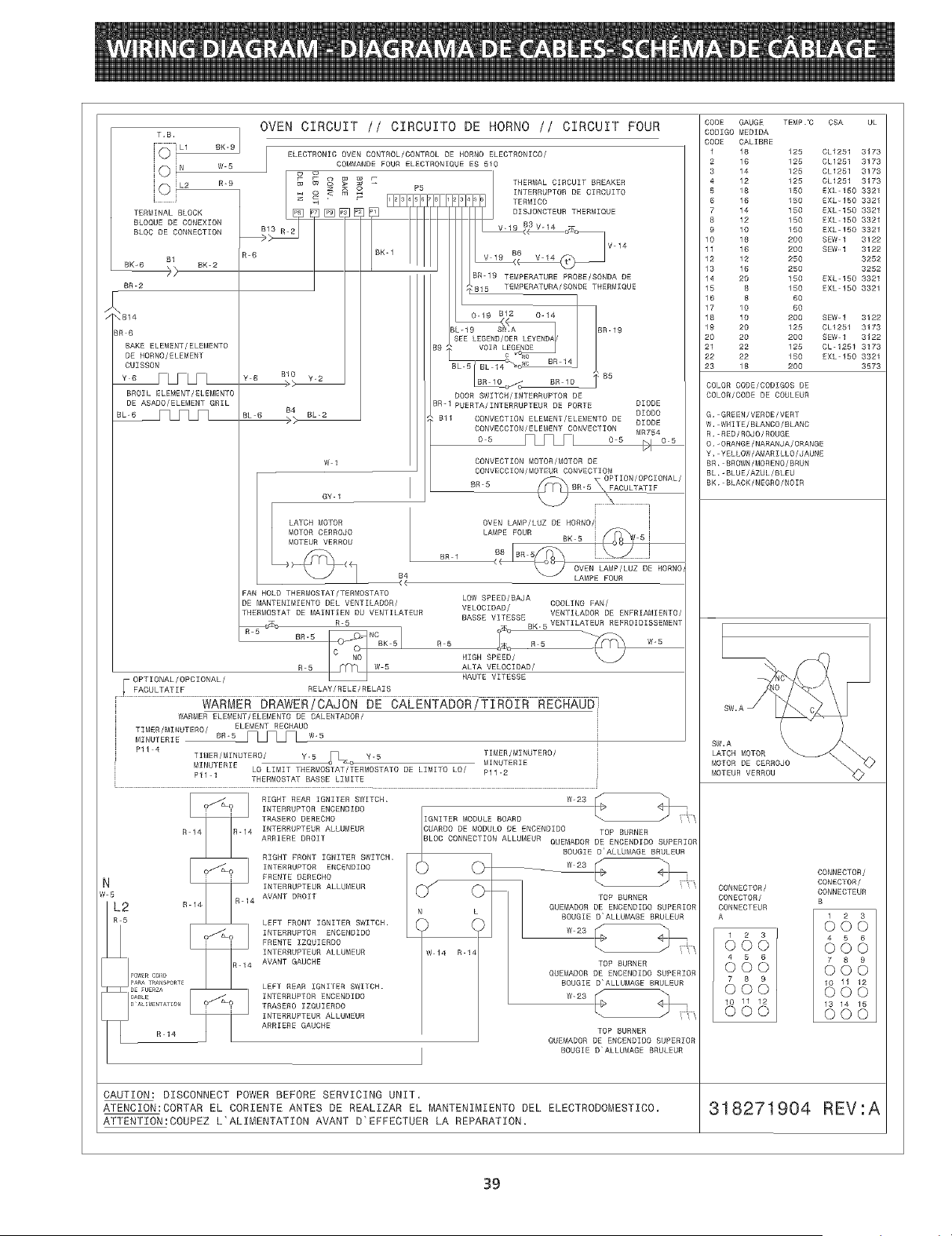
BR 2
:B14
T.B,
[oi N
[0_ E9
[ ]
TERMINAL BLOCK
BLOQUE DE OONEXION
BLOC DE CONNECTION
BK-2
_R 6
BAKE ELEMENT/ELEMENTO
DE HORNO/ELEMENT
CUISEOV
BROIL ELEMENT/ELEMENTO
DE ASADO/ELEMENT GRIL
_CCL Yl
OVEN CIRCUIT // CIRCUITO DE HORNO // CIRCUIT FOUR
BK-9 I
ELECTRONIC OVEN CONTROL/CONTROL DE HORNO ELECTRONICO/
W 5 COMMANDE FOUR ELECTRONIQUE ES 510
BIO Y 2
Y6 ) _....._
B4 BL_2
BL 6 >_
W 1
GY 1
LATCH VOTOR
MOTOR CERROJO
VOTEUR VERROU
FAN HOLD THERVOSTAT/TER_OSTATO
DE NANTENIMIENTO DEL VENTILADOR/
THERMOSTAT DE MAINTIEN DU VENTILATEUR
R-5
BR-5
CODE GAUGE TEMP."O CSA UL
CODIGO MEDIDA
CODE CALIBRE
1 18 125 CL1251 3173
2 16 125 CL1251 3173
3 14 125 CL1251 3173
4 12 IE5 CL1251 E173
5 18 150 EXL 150 3321
6 16 150 EXL-150 3321
7 14 150 EXL-150 3321
8 12 150 EXL 150 3321
9 10 150 EXL-150 3321
10 18 200 SEW 1 3122
11 IB 200 SEW1 3122
12 12 250 3252
13 16 250 3252
14 20 15E EXL-150 3321
15 8 150 EXL 150 3321
IE 8 BE
17 10 BE
18 10 20E SEW-1 3122
19 20 1E5 CL1251 3173
20 20 20E SEW 1 3122
21 22 125 CL-1251 3173
22 22 15E EXL 150 3321
2E 18 20E 3573
COLOR CODE/OOOIGOS DE
COLOR/CODE DE COULEUR
G, GREEN/VERDE/BERT
W. WHITE/BLANCO/BLANC
R,-RED/ROJO/ROUGE
O._ORANGE/NARANJA/ORANGE
Y,wYELLOW/AVARILLO/JAUNE
BR, BROWN/bIORENO/BRUN
BL,-BLUE/AZUL/BLEU
BK. BLACK/NEGRO/NOIR
R 14
N
W- 5
L2 n 14
PARARANSPORTE
DE FUERZ,_
CABLE
D ALI},IENTATION
DOOR SWITEH/INTERRUPTOR DE
BR-1PUERTA/INTERRUPTEUR DE PORTE
DIODE
DIODO
Bll CONVECTION ELEMENT/ELEMENTO DE DIODE
CONVECCION/ELEMENT CONVECTION MR754
oB CI CLYh oB
CONVECTION MOTOR/MOTOR DE
CONVECOION/MOTEUR CONVECTION
OPTIOV/OFOIONAL/
BR 5 gR-5_
FACULTATIF
N
BR I
OVEN LAMP/LUZ DE HORNO/i
LAMFE FOUR
BK 5
OVEN LAMP/LUZ DE HORNO,
LAMPE FOUR
LOW SPEED/BAJA
VELOC [DAD/ COOLING FAN/
BASSE VITESSE
R 5 l_ R 5
HIGH SPEED/
R_5 AL'fA VELOCI DAD /
OPTIONAL/OPCIONAL/ SAUTE VITESEE
_ FACULTATIF RELAY/RELE/RELAIE
i
l WARNER DRAWER/CAJON DE CALENTADOR/TIROIR RECHAUD
WARMER ELENENT/ELEMENTO DE OALENTADOR/
[ TIMER/MINUTERO/ ELEMENT RECHAUD
i VIRUTERIE BE-E_LCI W-S i
Pll 4 [
TIMER/MINUIERO/ Y-5 _L_ Y-s TIMER/MINUTERO/ [
MINUTERIE
NINUTERIE LO LIMIT THERMOSTAT/TERMOSTATO DE LIMITO LO/ P11-2
PI1 1
THERMOSTAT BABSE L!_ITE
L . i
_ RIGHT REAR IGNITER SWITCH,
INTERRUPTOR ENCENDIDO
TRASERO DERECHO
R-14 INTERRUPTEUR ALLUNEUR
ARRIERE DROIT
RIGHT FRONT IGNITER SWIICH,
_ INTERRUPTOR ENCENDIDOFRENTE OERECHO
INTERROPTEUR ALLUVEUR
R-14 AVANT DROIT
LEFT FRONT IGNITER SWITCH.
_ I NTERRUPTOR ENCENDIDOFRENTE IZQUIERO0
I NTERRUPTEUR ALLUMEUR
R 14 AVANT GAUCHE
LEFT REAR IGNITER SWITCH.
_ I NTERRUPTOR ENCEVDIDOIRASERO IZQUIERDO
I NTERRUPTEUR ALLUMEUR
ARRIERE GAUCHE
R 14
SW.A X
LATCH MOTOR
MOTOR DE CERROJO
BOTEUR VERROU
TOP BURNER
QUEMADOR DE ENCENDIDO SUPERIOR
BOUGIE DALLU_IAGE BRULEUR
TOP BURNER
QUEMADOR DE ENCENOIDO SUPERIOR
BOUGIE DALLUMAGE BRULEUR
CAUTION: DISCONNECT POWER BEFORE SERVICING UNIT.
ATENCION:OORTAR EL CORIENTE ANTES DE REALIZAR EL MANTENIMIENTO DEL ELECTRODOMESTICO.
ATTENTION:COUPEZ L'ALIMENTATION AVANT D'EFFECTUER LA REPARATION.
CONNECTOR/
CONECTOR/
CONVECTOR/ CONNECTEUR
CONECTOR/ B
CONNECTEUR
A 1 2 3
©©©
4 5 B
©©©
7 E 9
©©©
10 11 12
©©©
13 14 15
©©©
318271904 REV:A
39
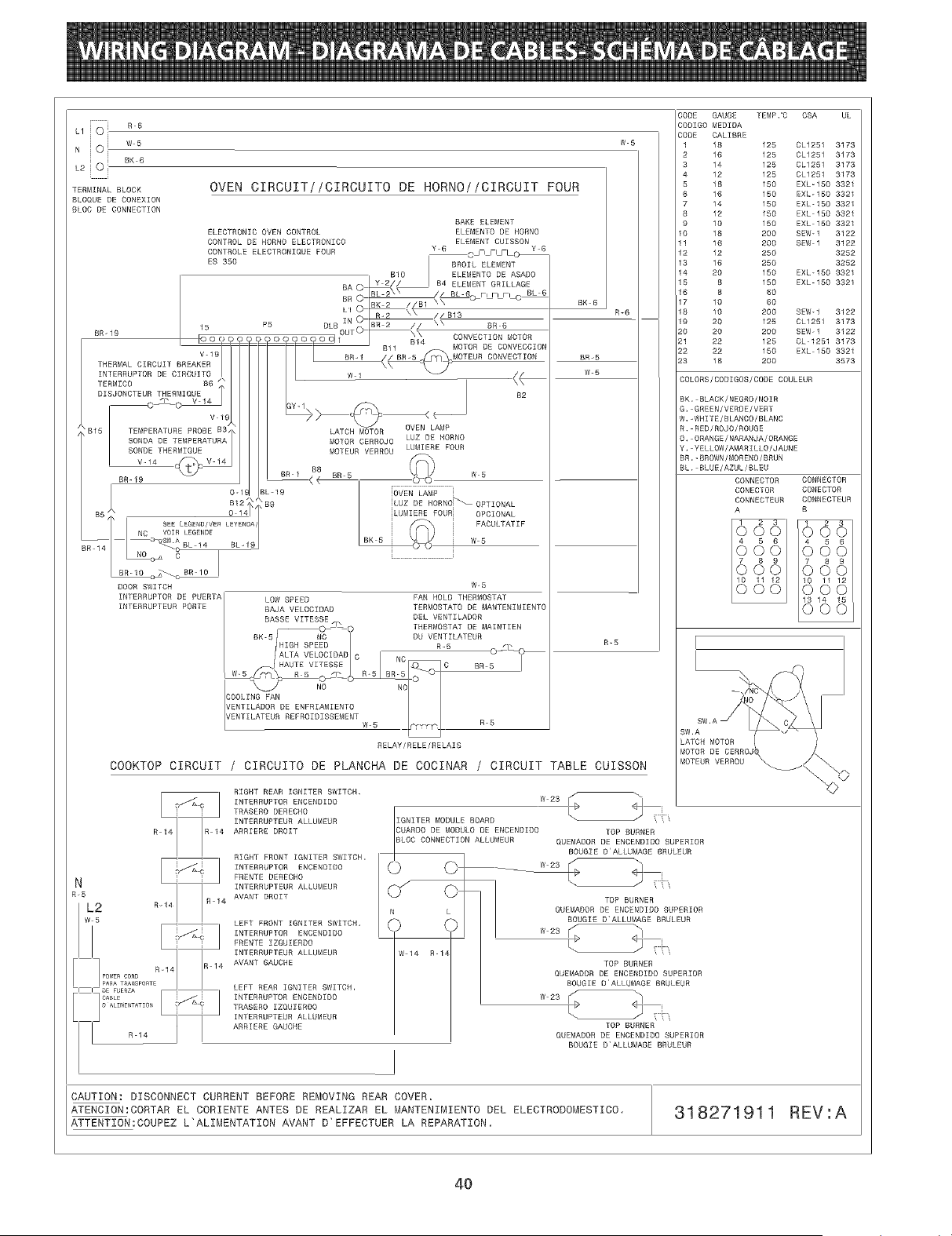
LliOi RR
N O I w5
L2JO! BK6
il
TERMINAL BLOCK
BLOQUE DE CONEXION
BLOC DE CONNECTION
ELECTRONIC OVEN CONTROL
CONTROL DE HORNO ELECTRONICO
CONTROLE ELECTRONIQUE FOUR
ES 350
BR-19
V-19
THERMAL CIRCUIT BREAKER
INTERRUPTOR DE CIRCUITO
TEBMICO B6
DISUONCTEUR THERMIQUE
0_0 V !4
)B15 TEMPERATURE PROBE B3
SONOA BE TEMPERATURA
SONDE THERMZQUE
V-14
BR-19 BR 1 [_ BR 5
BE o l
DOOR SWITCH
INTERRUPTOR DE PUERTA LOW SPEED
INTERRUPTEUR PORTE BAJA VELOCIBAD
BASBE VITESSE
W-5
W 5
OVEN CIRCUIT//CIRCUITO DE HORNO!/CIRCUIT FOUR
BAKE ELEMENT
ELEMENTO DE HORNO
ELEMENT CUISSON
Y B O" Ill FLc> Y 6
LATCH MOTOR OVEN LAMP
MOTOR CERROJO LUZ DE NORNO
MOTEUR VERROU LUt_IIEBE FOUR
[OVEN LAMP i
BK 6
R-B
BR-5
W-5
W 5
iLUZ BE BORNO_OPTIONAL
iLUMIERE FOUR i OPCIONAL
FACULTATIF
W5
W-5
FAN HOLD TBERf£1OSTAT
TERtv1OSTATO DE MANTENIMIENTO
DEL VENTILADOR
THERMOSTAT DE t_AINTIEN
DU VENT_LATEUR
R_ 5 ©_b
BR 5
W5 R5
R_R
RELAY/RELE/RELAIS
COOKTOP CIRCUIT
R-14 R 14
N E'_
R_5
L2 R14 R 14
w 5
R 14
I I DE FUEaZA _
El.....
o ALIME[TATIO[
R-14
/ CIRCUITO DE PLANCHA DE COCINAR / CIRCUIT TABLE CUISSON
RIGHT REAR IGNITER SWITCH,
INTERRUPTOR ENCENDIDO
TBASERO DERECBO
INTERRUPTEUB ALLUMEGR
ABRIERE ORBIT
RIGHT FRONT IGNITER SWITCH.
INTERRUPTOR ENCENDIDO
FRENTE DEBECHO
ZNTBRRUPTEUR ALLUMEUR
AVANT ORBIT
LEFT FRONT IGNITER SWITCH.
INTERRURTOR ENCENDIDO
RREMTE IZGUIERDO
INTERRUPTEUR ALLUMEUR
AVANT GAUCHE
LEFT REAR IGNITER SWITCH.
INTEBRUPTOR ENOENDIDO
TBASEBO IZQUIERDO
INTERRUPTEUR ALLUMEUR
ARRIERE GAUCHE
CODE GAUGE TEMP,"C CSA UL
CODIGO MEDIBA
CODE CALIBRE
1 18 125 CL1251 3173
2 16 125 BL1251 3173
3 14 125 CL1251 3173
4 12 125 CL1251 3173
5 18 150 EXL-IBO 3321
B 16 150 EXL-150 3321
7 14 150 EXL-150 3321
8 12 150 EXL 150 3321
9 10 150 EXL-150 3321
10 18 200 SEW-1 3122
11 16 200 SEW 1 3122
12 12 250 3252
13 16 250 3252
14 20 150 EXL-150 3321
15 8 150 EXL 150 3321
16 8 60
17 10 60
18 10 200 SEW-1 3122
19 20 125 CL1251 3173
20 20 200 SEW-I 3122
21 22 125 CL-1251 3173
22 22 150 EXL 150 3321
23 18 200 3573
COLORS/COBIGOS/CODE COULEUR
BK. BLACK/NEGRO/NOIR
G, GREEN/VERDE/VERT
W,-WMITE/BLANCO/BLANC
R, RED/ROJO/ROUGE
O, ORANGE/NARANJA/ORANGE
Y. YELLOW/AMARILLO/JAUNE
BB,-BROWN/MOBENO/BRUN
BL. BLUE/AZUL/BLEU
CONNECTOR CONNECTOR
CONECTOR CONECTOR
CONNECTEUR CONNECTEUR
A B
66&I 6661
666 666
666
SW,A
LATCH MOTOR
MOTOR DE CERRO
bIOTEUR VERROU
w23
TOP BURNER
OUEMADOR DE ENCENDIDO SUPERIOR
BOUGIE B ALLUfvlAGE BRULEUB
w23
TOP BURNER
QUEMADOR DE ENCENDIBO SUPERIOR
BOUCLE D'ALLUMAGE BRULEUB
g
TOP BURNER
QUEMADOR DE EMCEMDIDO SUPERIOR
BOUGIE D ALLUI_AGE BRULEUR
w23 ;,
TOP BURNER
QUEMADOR BE ENCENDIOO SUPERIOR
BOUGIE D'ALLUMAGE BRULEUR
CAUTION: DISCONNECT CURRENT BEFORE REMOVING REAR COVER.
ATENCION:CORTAR EL CORIENTE ANTES DE REALIZAR EL MANTENINIENTO DEL ELECTRODOMESTICO,
ATTENTtON:COUPEZ L'ALtNENTATtON AVANT D'EFFECTUER LA REPARATION.
318271911 REV:A
40
