Installation Guide
Outdoor CPE
Get Started with Setup Videos
Scan the QR code or visit
https://www.tp-link.com/support/setup-video/

Contents
Overview 01
Package Contents 01
Hardware Overview 02
Application Example 04
Hardware Connection 05
Site Consideration 05
Hardware Installation 07
Power Supply 14
Lightning & ESD Protection 15
Installer Compliance Responsibility 16
Software Conguration 17
Logging in to the PharOS 17
Conguration for a Typical Application 18
Antenna Alignment 20
Specications 21
FAQ 22
01
Overview
TP-Link's Pharos series outdoor CPEs are dedicated to outdoor
wireless network solutions.
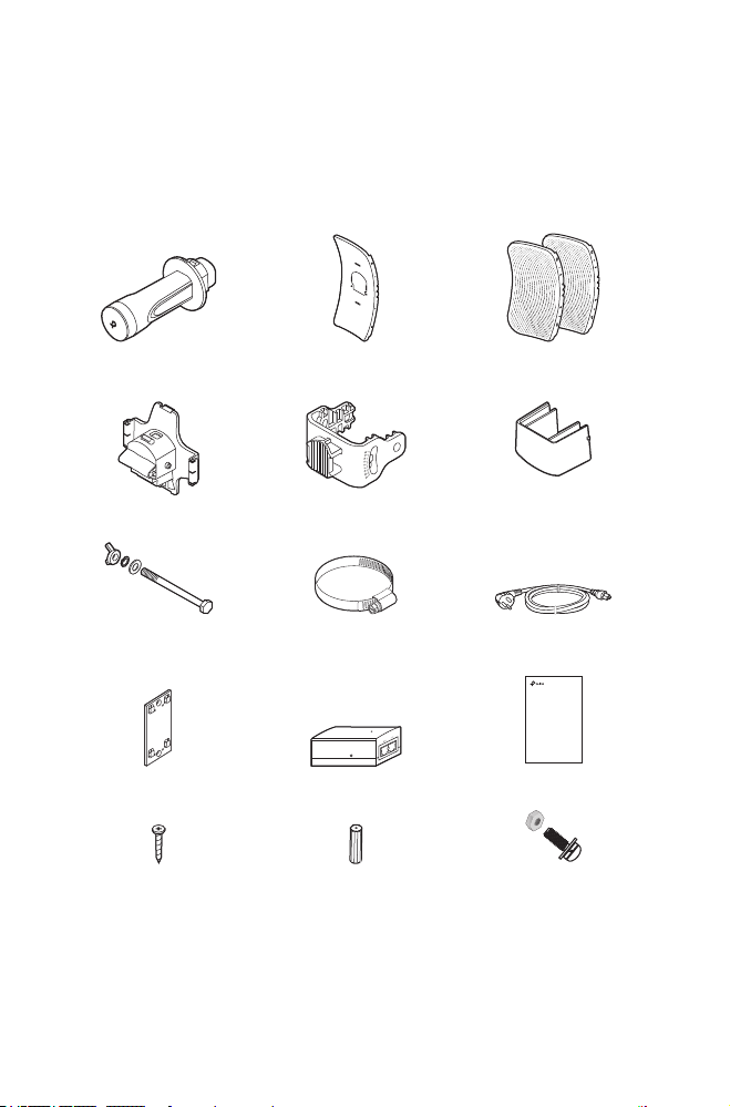
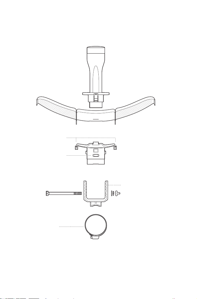
Package Contents
Installation Guide
Outdoor CPE
Pharos CPE
Rear Cover
Center Reector Panel Side Reector Panels
(Qty.2)
Mounting Bracket
(For CPE)
Protective Cap
Power CordHexagon Bolts with Wing Nut
and Washer Assemblies
(M6x79)
Metal Strap
Mounting Bracket
(For PoE Adapter)
Passive PoE Adapter Installation Guide
ST3×16 Self-tapping Screws
(Qty.2)
D3×28 Plastic Wall Anchors
(Qty.2)
Four M2.5*8 Combination Screws
with M2.5*2 Nuts
(QTY.4)
(Only for CPE710)
02
Hardware Overview
• Bottom View
Reflector Assembly
Securing Arms
Bubble Level
Mounting Bracket
Rear Cover
Metal Strap
03
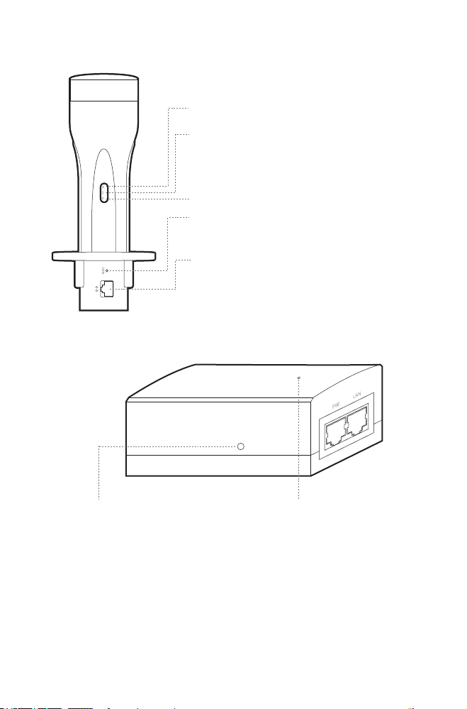
• Panel Layout
On:
A device is connected to the ETHERNET port,
but there is no activity.
Flashing: A device is connected to the
ETHERNET port and is active.
On: The CPE is powered on.
On: The wireless function is enabled.
RESET
Press and hold for 5 seconds to reset the CPE to
its factory defaults.
ETHERNET
The port is used to connect to the POE port of
the provided PoE adapter for both data
transmission and power supply through Ethernet
cabling.
• Passive PoE Adapter
Power LED
On: The CPE is powered on.
Off: The CPE is powered off.
Remote Reset
Press and hold for about 5 seconds to reset
the CPE to its factory defaults.
04
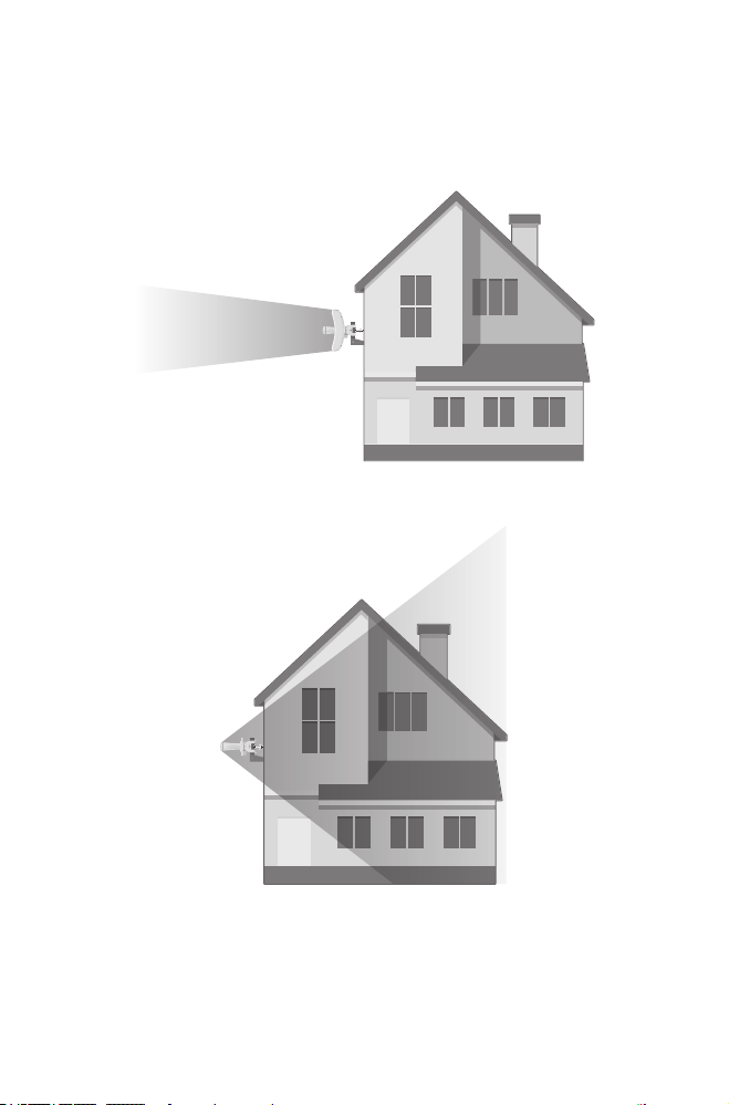
Application Example
The CPE device with the reector installed provides outdoor
network access over long distances for point-to-point
applications.
The CPE device without the reector installed provides outdoor
-to-indoor Wi-Fi coverage with the Feed only mode.
05
Hardware Connection
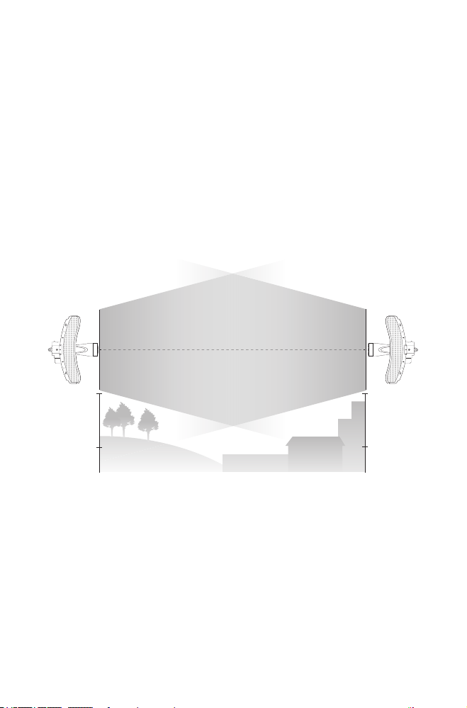
Site Consideration
• Mounting Height
Ensure a clear line of sight between the wireless devices for
optimum performance. An elevated location is recommended
as obstacles like trees, buildings and large steel structures will
weaken the wireless signal. See ‘Q2’ in ‘FAQ’ for details about how
to calculate the minimum mounting height of the devices.
Line of Sight
Side View
06
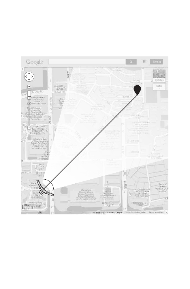
• Orientation
Install the CPE devices and make sure that they point towards
the devices that will receive the signal. You can orient the devices
with the help of Google Maps, GPS and some landmarks. The
horizontal bandwidth of CPE605/CPE710 is 7°.
A
shenzhen
B
Line of Sight
Horizontal
Beamwidth
07
Hardware Installation
TERMS OF USE: TP-Link’s Pharos series outdoor CPEs must be
installed by a certied professional. Installers must abide by local
rules and regulations in terms of legal frequency channels, output
power, and Dynamic Frequency Selection (DFS) requirements.
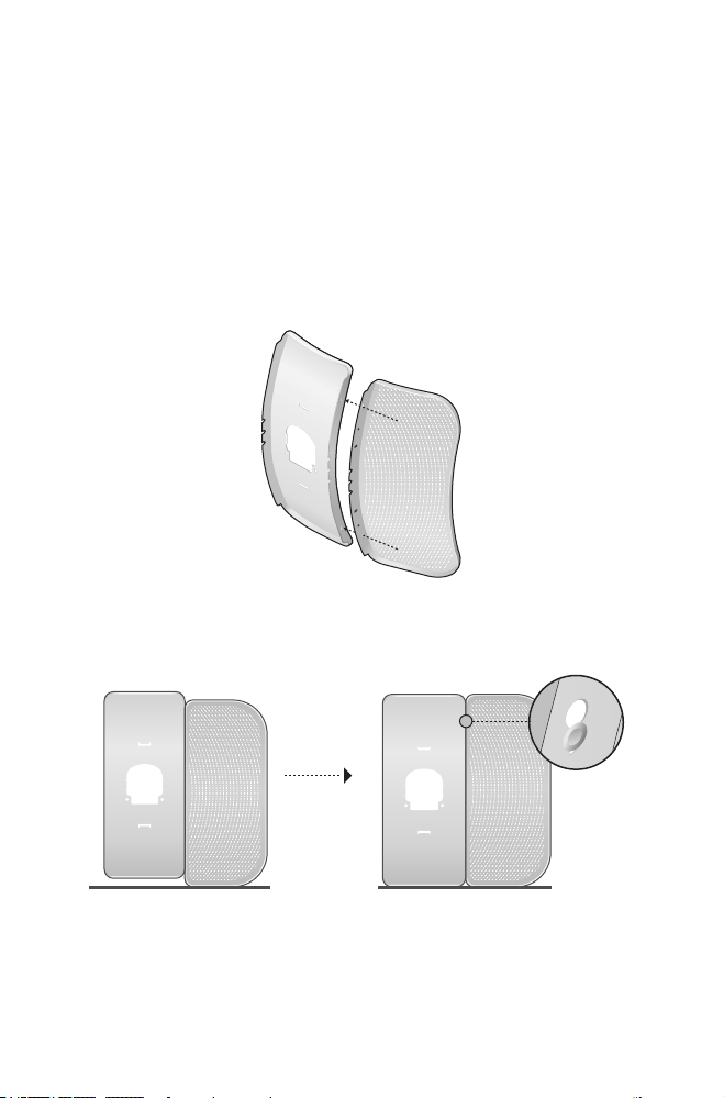
1. Attach the Side Reector Panels to the Center Reector Panel
as follows:
a. Insert the two mounting studs on the Center Reector Panel
into the large opening of the slots on the Side Reector Panel.
b. Slide the Side Reector Panel until the mounting studs are
positioned over the narrow opening of the slots, and the top
edges of the panels should be aligned when done.
08
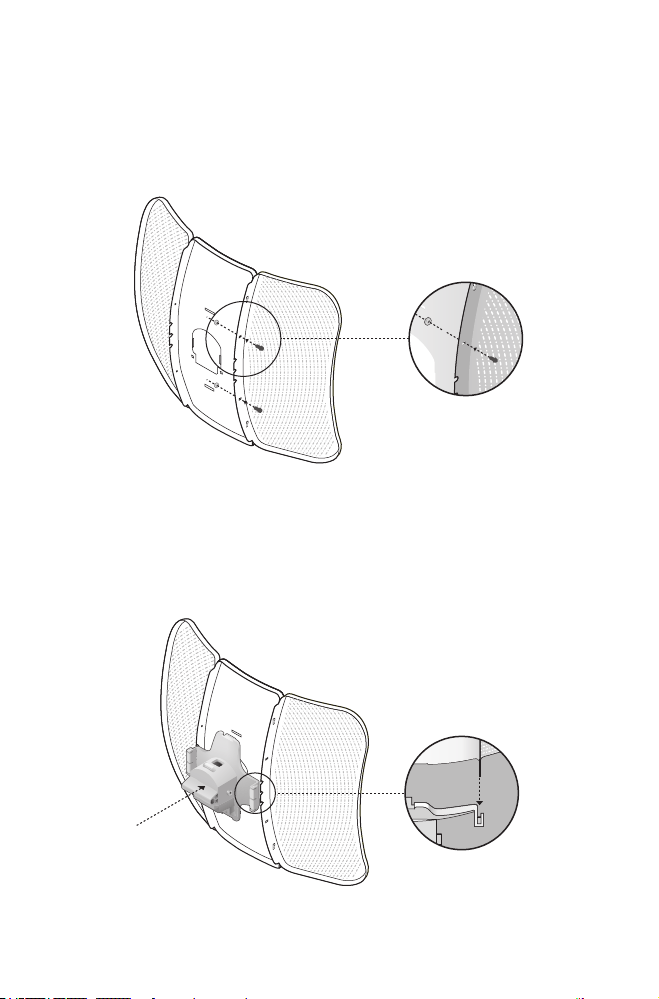
c. Repeat step a and step b to attach the other Side Reector
Panel.
d. Attach the Side Reector Panels to the Center Reector Panel
more securely using four M2.5*8 combination screws with
M2.5*2 nuts (only provided with CPE710).
2. Attach the Rear Cover to the reector assembly as follows:
a. While holding the reector assembly, align the raised edges
on the back with the Securing Arms of the Rear Cover, and
align the Snap Hooks on the Rear Cover with the slots on the
Center Reector Panel.
09
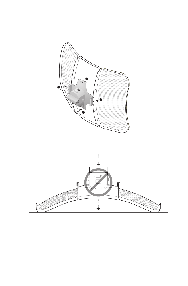
b. Attach the Rear Cover to the reector assembly. Press upon
the Rear Cover at the four positions marked in the diagram
below in sequence until it locks into place.
1
2
4
3
WARNING:To avoid damage, do not place the panels on a at
surface or push down on it.
10
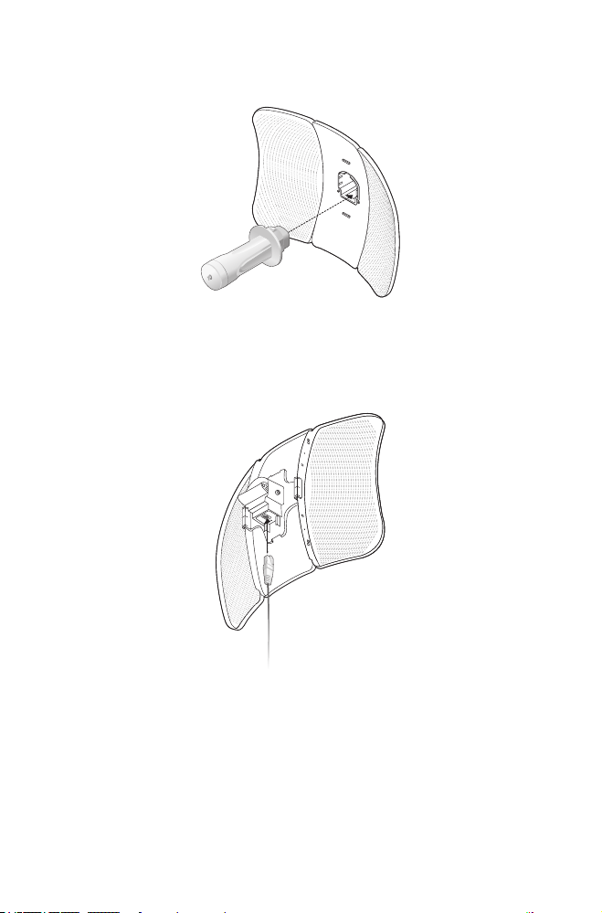
3. Insert the Pharos CPE into the Rear Cover until the CPE locks
into place.
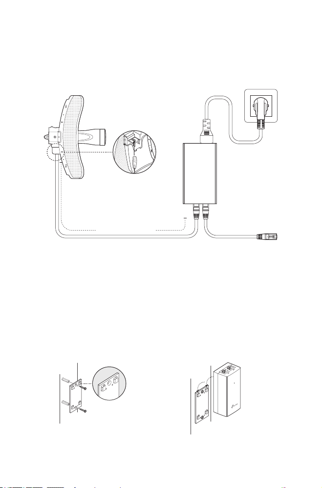
4. Connect the Ethernet cable to the Pharos CPE.
a. Connect the Ethernet cable to the Ethernet port.
Note: The length of the Ethernet cable is up to *60m for steady
power supply.
* Power supply distances are based on test results under
normal usage conditions. Actual power supply distance
will vary as a result of 1) AP status, including transmit
power, connected devices and network trac and 2) cable
properties, including type and texture.
11
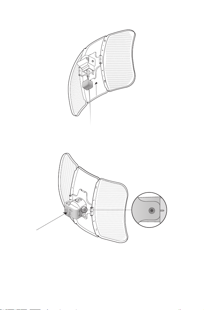
b. Attach the Protective Cap to the Rear Cover
5. Attach the Mounting Bracket to the Rear Cover until the grooves
on the Mounting Bracket are positioned over the pins on the
Rear Cover.
12
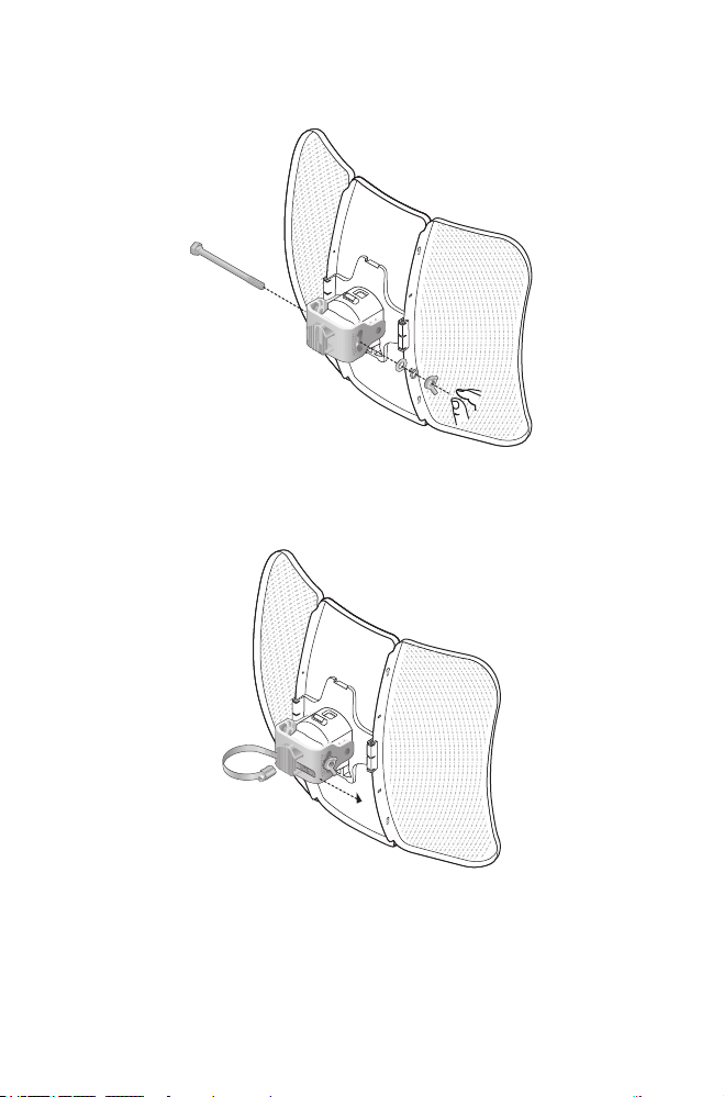
6. Secure the Mounting Bracket to the Rear Cover using M6x79
Hexagon Bolts with Wing Nut and Lock Washer Assemblies.
7. Attach the CPE assembly to the pole using the metal Strap.
a. Open the Mental Strap and feed it through the two slots of
the Ball joint Mount.
13
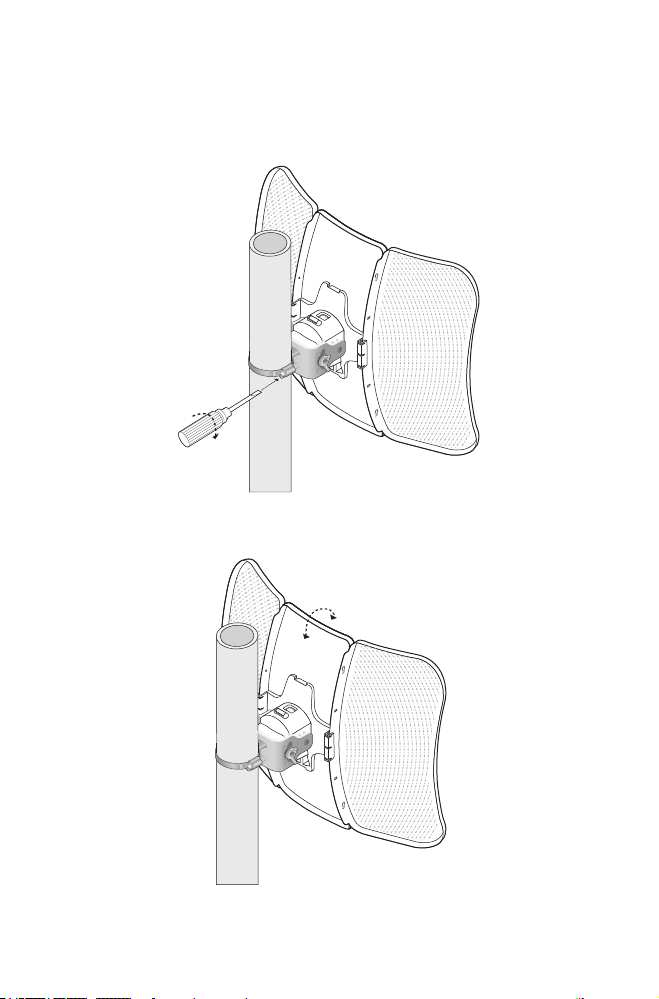
b. Wrap the metal strap around the pole. Use a socket wrench or
screwdriver to turn the screw clockwise and securely fasten
the strap to the pole.
Note: Suitable pole diameters range from 15mm to 70mm.
8. Adjust the azimuth and elevation angle of the CPE device to
achieve maximum signal strength.
14
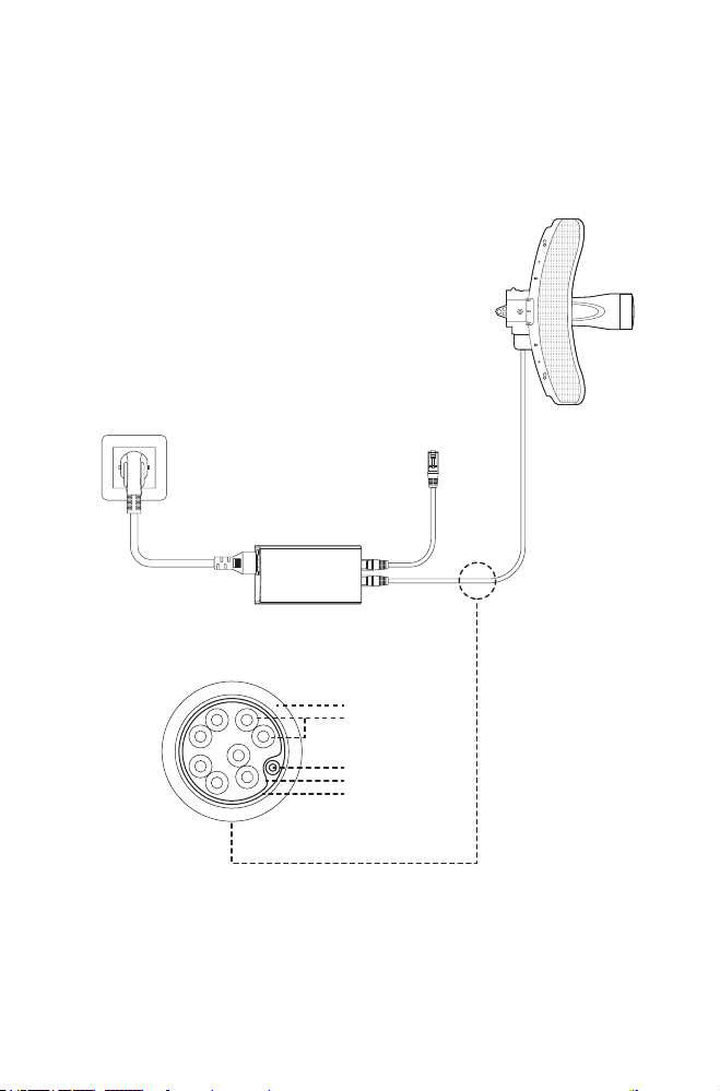
Power Supply
• Connecting the PoE Adapter
Connect the devices as shown in the gure below.
PoE LAN
Ethernet cable
length up to 60m
• Mounting the PoE Adapter (Optional)
Note: To ensure the passive PoE adapter is attached most
securely, it is recommended to install the adapter with the
Ethernet port facing upward.
1. Drill two holes on the wall
and insert the plastic wall
anchors into the the holes.
Secure the mounting
bracket to the wall.
2. Attach the passive PoE
adapter to the mounting
bracket by sliding the adapter
in the direction of the arrows
until it locks into place.
15
Lightning & ESD Protection
Proper grounding is extremely important for outdoor devices.
By using shielded CAT5e (or above) cable with ground wire and
the provided PoE adapter, you can eectively eliminate ESD
attacks.
CPE
PoE Adapter with
Earth Ground
Shielded CAT5e (or above)
Cable with Ground Wire
Grounded 3-wire
Power Outlet
Twisted Pair
Ground Wire
Secondary Cable Shield
Cable Shield
Sheath
16
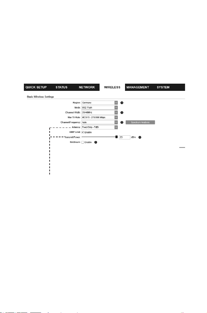
Installer Compliance Responsibility
Devices must be professionally installed and it is the professional
installer’s responsibility to make sure the device is operated within
local rules and regulations.
Since TP-Link’s Pharos outdoor CPE can be paired with a variety
of antennas, the Antenna and Transmit Power elds are provided
to the professional installer to assist in meeting regulatory
requirements.
Refer to Antenna and Transmit Power elds to make sure the devices are
operated within local rules and regulations.
17
Software Conguration
This chapter introduces the login to the PharOS Web Interface
and the software congurations.
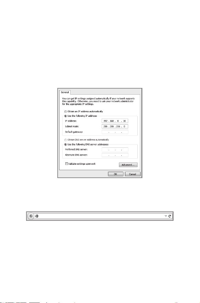
Logging in to the PharOS
1. Before accessing the PharOS Web Interface, you need to
assign a static IP address 192.168.0.X (X ranges between 2 and
253, e.g. 192.168.0.10) to your computer.
2. Open a web browser, type http://192.168.0.254 into the
address eld and press Enter (Windows) or return (Mac). It is
recommended to use the latest version of Google Chrome,
Firefox or Safari.
192.168.0.254
3. Enter admin for both User Name and Password, then select
the Language from the drop-down list. Read and agree to the
terms of use, then click Login.

18
4. Change the default User Name and Password for security
purposes. You can then start to congure your CPE.
Note: For subsequent logins, use the new username and
password.
For more congurations, please visit
https://www.tp-link.com/support to download the User Guide of
Pharos products in the download center.
Conguration for a Typical Application
The typical topology is as follows: Multiple wireless bridges
are built among the access point and the clients. Follow the
instructions below to congure the Access Point and the Clients.
For simplicity, we will take one wireless bridge as an example.
Access Point
Client
Client
Client
• Congure the Access Point (AP)
1. Log in to PharOS and go to the Quick Setup page.
2. Operation Mode: Select Access Point and click Next.
3. LAN Settings: Click Next.
4. Wireless AP Settings:
a. Create a new SSID (Network name) for your wireless network.
b. Select WPA-PSK/WPA2-PSK for the Security method and
create a PSK Password to protect your AP.
c. Enter the distance between the Access Point and the Client
into the Distance Setting eld.

19
d. Select the MAXtream checkbox (Refer to Q3 in FAQ for
details about MAXtream), and click Next.
5. Finish: Verify your settings and click Finish to complete the
conguration.
• Congure the Client
1. Log in to PharOS and go to the Quick Setup page.
2. Operation Mode: Select Client and click Next.
3. LAN Settings: Change the IP Address to 192.168.0.X (X ranges
between 2 and 253), the same subnet as the access point, and
click Next.
4. Wireless Client Settings:
a. Click Survey and select the SSID of the Access Point in the
AP list, then click Connect.
b. Select WPA-PSK/WPA2-PSK from the Security option, enter
the same PSK password and distance value of the Access
Point, then click Next.
5. Finish: Verify your settings and click Finish to complete the
conguration.
For more congurations, please visit
https://www.tp-link.com/support to download the User Guide of
Pharos products in the download center.
20
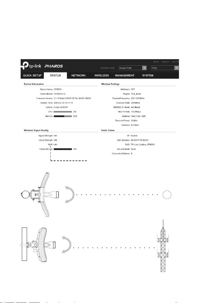
Antenna Alignment
In order to get the best performance, you can precisely align the
direction of the CPE with the assistance of Wireless Signal Quality
on the STATUS page of the PharOS Web Interface.
Adjust the direction of the CPE until the
SNR reaches a maximum.
WBS+Antenna
WBS+Antenna

21
Specications
HARDWARE FEATURES
Interface
10/100 Mbps Ethernet port (for CPE605)
10/100/1000 Mbps Ethernet port (for CPE710)
Button RESET: Restore the device to its factory defaults
Power Supply 24 V passive PoE adapter included
ESD Protection *15 KV
Lightning Protection Up to *6 KV
Operating Temperature -40°C to 70°C (-40°F to 158°F)
Operating Humidity 10% to 90%
Certication CE, FCC, RoHS, IP65
WIRELESS FEATURES
Antenna Gain 23 dBi
Antenna Beamwidth
Azimuth: 7°
Elevation: 9° (for CPE710), 10° (for CPE605)
802.11 Standards
11a/n (for CPE605)
11a/n/ac (for CPE710)
Note: *Estimation is based on shielded CAT5e(or above) cable with an integrated
grounding wire.
22
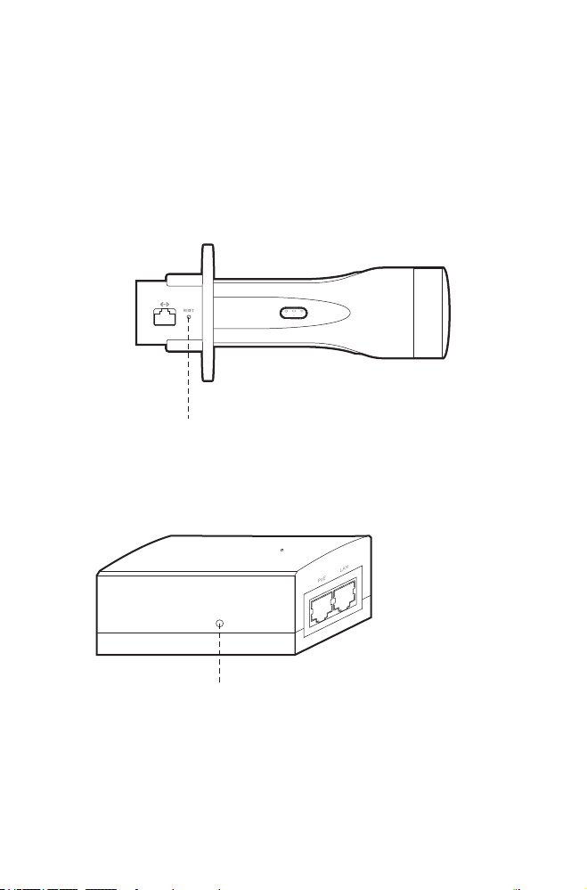
FAQ
Q1. How to restore the CPE to its factory default
settings?
Method 1:
With the CPE powered on, press and hold the RESET button on the
CPE for about 5 seconds.
RESET Button:
Press & hold for about 5 seconds
Method 2:
With the CPE powered on, press and hold the Remote Reset button
on the passive PoE adapter for about 5 seconds.
Remote Reset Button:
Press & hold for about 5 seconds
23
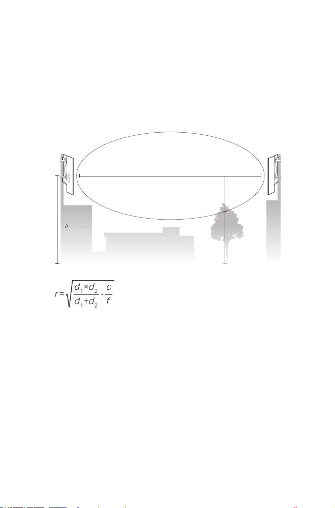
Q2. How to calculate the minimum mounting height
of the devices?
In order to maximize the received signal strength of the devices,
installers need to minimize the effect of the out-of-phase signals,
which is caused by obstacles in the path between the transmitter
and the receiver. Fresnel Zone is a usual method to calculate this
path, as shown in the formula and the gure below.
h = the height of
obstacle at this point
H h+r
*
(1 40%)
(H is the height of the CPE)
d
2
r
d
1
where,
r = Fresnel zone radius in meters
c = 3x10
8
m/s, speed of light
f = operating frequency of the devices in
Hz
d
1
& d
2
= the distances between the
point and the devices in meters
For example, assume d
1
is 2 km, d
2
is 8 km, and f is 2.4 GHz, then
r would be 14.142 m. Considering a toleration of 40%, allowable
radius would be 8.485 m. Assume h is 10 m, then the result of the
minimum mounting height based on this point would be 18.485 m.
Similarly, calculate the results based on all the points where there are
obstacles, and the maximum value would be the nal result.
For more information, please refer to:
https://en.wikipedia.org/wiki/Fresnel_zone

24
Q3. What is Pharos MAXtream?
Pharos MAXtream is a proprietary protocol developed on the basis
of Time Division Multiple Access (TDMA) by TP-Link.
The MAXtream technology has the following advantages:
• Eliminates hidden node collisions and improves channel eciency.
• Lower latency, higher throughput, larger network capacity and
more stability.
• Improves the QoS for video, voice and sound data stream.
By dividing the timing of transmission into different time slots,
MAXtream allows the Pharos devices to transmit in rapid succession,
one after another, each using its own time slot to transmit and
receive their own frames, which greatly reduces the chance of
collision.
Pharos MAXtream is a non-standard Wi-Fi protocol that is only
compatible with TP-Link’s Pharos series products. Please notice
that you will not be able to connect other Wi-Fi devices to an AP with
MAXtream enabled.
Q4. How can I use Spectrum Analysis to nd the
appropriate channel for the devices?
1. Log in to PharOS, click Spectrum Analysis in the tools drop-down
list, a window will pop up to remind you that all wireless connections
will be lost during spectrum analysis. Click Yes to continue to the
Spectrum Analysis page.
2. Click Start, the Pharos will begin to analyze the power of frequency.
Observe the curves for a period of time, and then click Stop. Note
that the relatively low and continuous part of the average curve
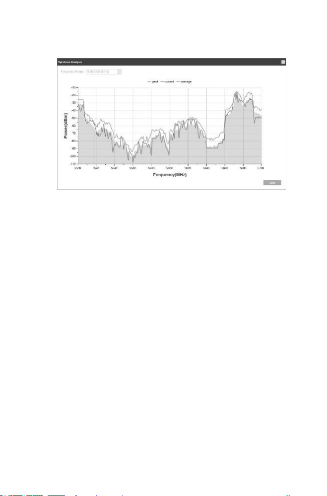
25
indicates less radio noise. Here, we use the figure below as an
example.
3. When choosing channel/frequency, you should avoid the spectrum
with large radio noise. In this example, the recommended channel/
frequency is 112/5560 MHz.

Safety Information
• Keep the device away from water, re, humidity or hot environments.
• Do not attempt to disassemble, repair, or modify the device.
• Do not use damaged charger or USB cable to charge the device.
• Do not use any other chargers than those recommended.
• Do not use the device where wireless devices are not allowed.
• Adapter shall be installed near the equipment and shall be easily
accessible.
The products of TP-Link partly contain software code developed by third parties, including software code subject
to the GNU General Public License (“GPL”). As applicable, the terms of the GPL and any information on obtaining
access to the respective GPL Code used in TP-Link products are available to you in GPL-Code-Centre under
(https://www.tp-link.com/en/support/gpl/). The respective programs are distributed WITHOUT ANY WARRANTY
and are subject to the copyrights of one or more authors. For details, see the GPL Code and other terms of the
GPL.
©2020 TP-Link
7106508556 REV1.1.0
To ask questions, find answers, and communicate with TP-Link users or engineers,
please visit https://community.tp-link.com to join TP-Link Community.
For technical support, the user guide and other information, please visit https://
www.tp-link.com/support, or simply scan the QR code.
If you have any suggestions or needs on the product guides, welcome to email
techwriter@tp-link.com.cn.