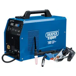
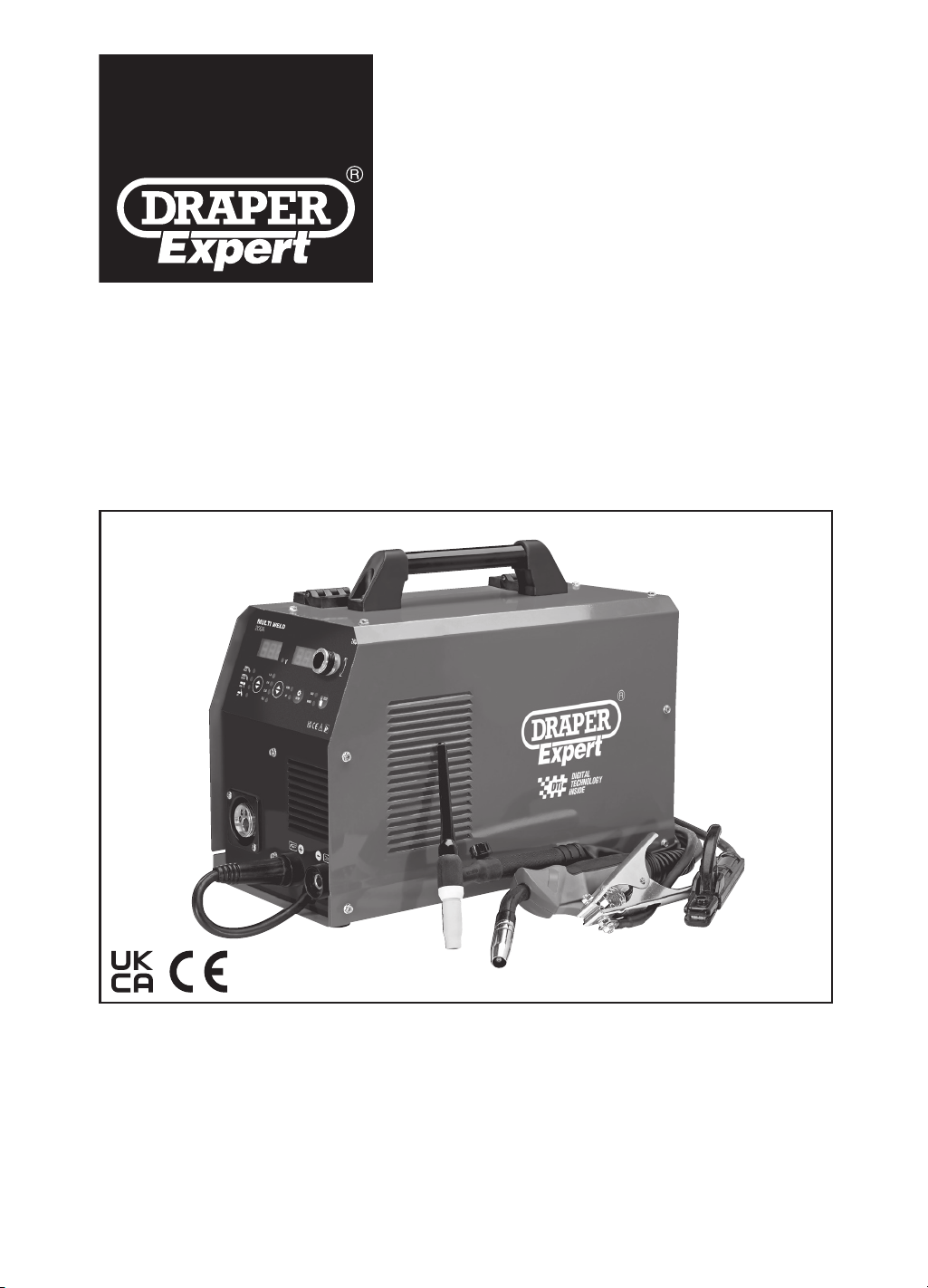
3-IN-1
200A MULTI PROCESS
WELDER
70043
These instructions accompanying the product are the original instructions. This document is part of the product,
keep it for the life of the product passing it on to any subsequent holder of the product. Read all these instructions
before assembling, operating or maintaining this product.
This manual has been compiled by Draper Tools describing the purpose for which the product has been designed,
and contains all the necessary information to ensure its correct and safe use. By following all the general safety
instructions contained in this manual, it will ensure both product and operator safety, together with longer life of the
product itself.
All photographs and drawings in this manual are supplied by Draper Tools to help illustrate the operation of the
product.
Whilst every effort has been made to ensure the accuracy of information contained in this manual, the Draper
Tools policy of continuous improvement determines the right to make modications without prior warning.
1. INTRODUCTION
1.1 SCOPE
This welder integrates MIG/MAG gas welding, ux-cored
wire welding, MMA welding and TIG lift welding. Under
the MIG welding process, the wire speed and working
voltage are automatically matched at optimal status. The
welder is suitable to weld a wide range of materials like
low carbon steel, low alloy steel, stainless steel,
aluminium, etc.
This product is Intended for trade use with the quality &
features to meet and exceed the expectations of the
most demanding user. Any application other than that it
was intended for, is considered misuse.
This product is not a toy and must not be used by
children or any person with reduced physical, sensory or
mental capabilities or lack of experience and knowledge,
or people unfamiliar with these instructions.
Local regulations may restrict the age of the operator.
1.2 UNDERSTANDING THIS MANUALS
SAFETY CONTENT:
Warning! – Information that draws attention to the
risk of injury or death.
Caution! – Information that draws attention to the risk of
damage to the product or surroundings.
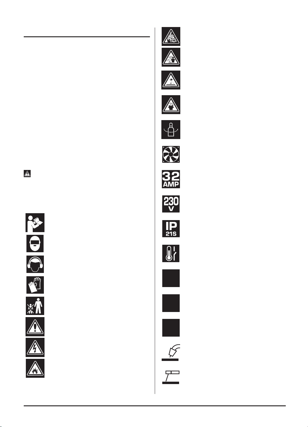
1.3 EXPLANATION OF SYMBOLS
Warning!
Read the instruction manual.
Warning!
Wear suitable welding eye/face protection.
Warning!
Wear ear defenders (During grinding
operations).
Warning!
Wear protective gloves.
Keep out of the reach of children.
Warning!
Danger of electric shock.
Danger of re.
Danger of explosion.
Danger of fumes.
Danger of ultraviolet radiation.
Danger of burning splashes.
Gas bottle to be secured by chain.
Fan cooled.
Input current.
Input voltage.
Protection rating.
Thermal overload.
MMA range.
MIG range.
TIG Lift range.
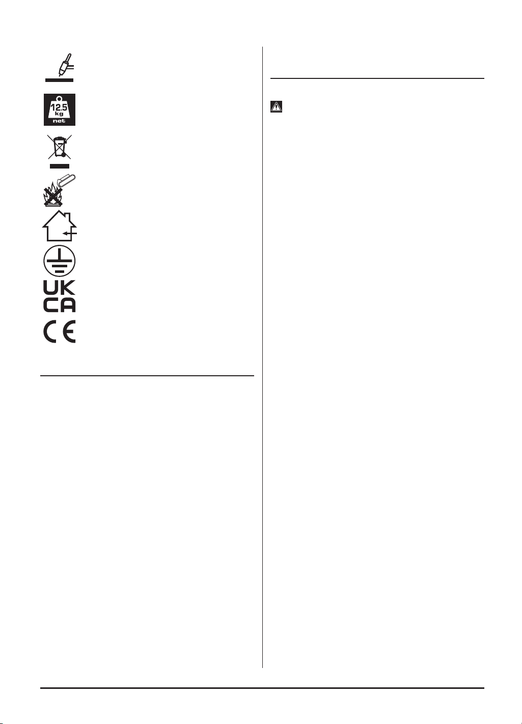
MIG welding (Metal Inert Gas) or
GMAW (Gas Metal Arc Welding).
ARC welding (stick), MMA ( Manual Metal
Arc) or
SMAW (Shielded Metal Arc Welding).
–
2
–
–
3
–
TIG welding (Tungsten Inert Gas) or
GTAW (Gas Tungsten Arc Welding).
Machine weight.
WEEE –
Waste Electrical & Electronic Equipment.
Do not dispose of Waste Electrical & Electronic
Equipment in with domestic rubbish.
Do not incinerate or throw
onto re.
For indoor use only.
Do not expose to rain.
Class 1 appliance
(Must be earthed).
UK Conformity Assessed.
European conformity.
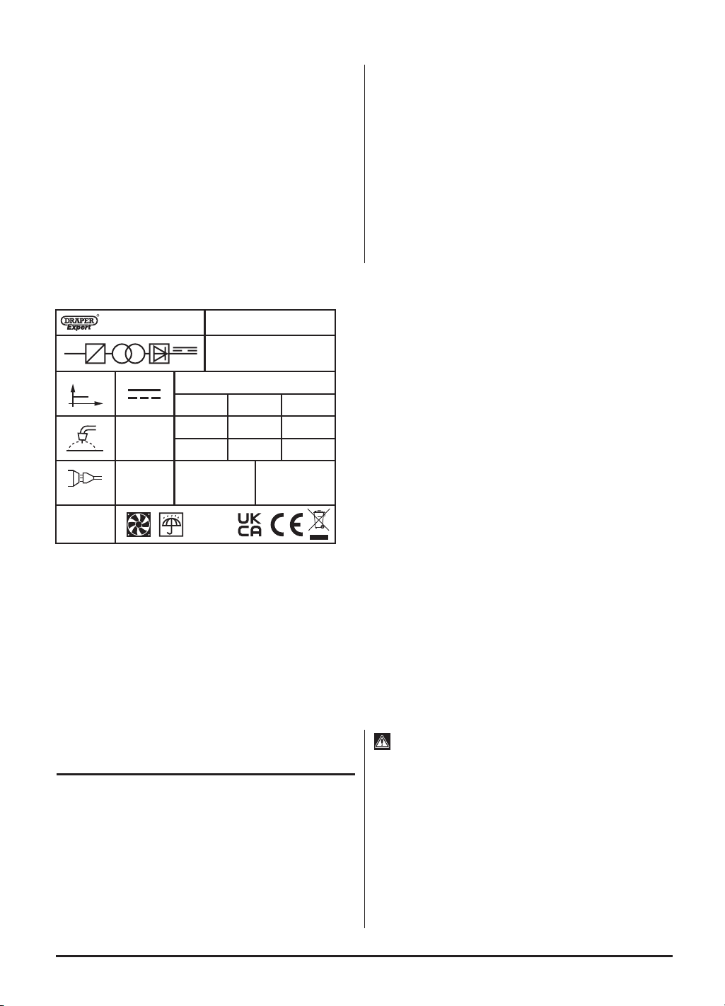
2. SPECIFICATION
2.1 SPECIFICATION
Stock No. .............................................................. 70043
Part No. ........................................................... MW200A
Rated voltage .................................................. 230~50Hz
Input current .............................................................. 32A
Current range
MIG ........................................................ 30 - 200A
TIG ......................................................... 20 - 200A
MMA ...................................................... 20 - 200A
MIG wire range ............................................. 0.6 - 1.2mm
MMA Electrode size ......................................1.6 - 5.0mm
MIG Wire Spool .......................................................... 5kg
Dinse Type Socket ................................................10 / 25
Degree of protection .............................................. IP21S
Cooling ............................................................... Air (fan)
Insulation class .............................................................. F
Duty cycle: ........................ 60% @ 200A / 100% @ 160A
Weight (Gross/Net/machine only) ........... 14.5/13.7/10kg
3. HEALTH AND SAFETY
INFORMATION
3.1 General Safety Instructions
Warning! Read all safety warnings and all
instructions. When using electric tools basic safety
precautions should always be followed to reduce the risk
of re, electric shock, and personal injury including the
following.
Read all these instructions before attempting to operate
this product and save these instructions.
Electric shock can kill:
– Remove the plug from the socket before carrying out
adjustment, servicing, or maintenance.
– Allow 5 minutes waiting time for the capacitors to
discharge before removing the panels for any
maintenance operations
– Do not touch live electrical parts.
– Never use electrode holders or cables with damaged
or deteriorated insulation.
– Keep the working environment, equipment, cables,
and clothing free from grease, oil, moisture, and dirt.
– Ensure the welding machine has been correctly
earthed and all panels are tted securely.
– The operator must be insulated from the oor and
workbench using a dry insulation mat.
– Wear isolating footwear and gloves that are in good
condition, i.e. without holes.
– In hazardous conditions of increased electric shock
always ensure a second person is present in case of
an accident.
– Never change electrodes with bare hands or damp
gloves (for ARC/MMA welders).
– Keep welding cables away from power cables.
– Regularly inspect the condition of the welding, earth,
and power cables for signs of damage.
– Do not leave the machine unattended and remove
the plug from the socket when not in use.
– Do not use welding cables unsuitable for the
amperage.
– Ensure the earth clamp is adjacent to the weld seam,
secured to bare metal and when not in use is
insulated for safety.
– Keep all equipment well maintained.
– The operator shall prevent gas cylinders in the
vicinity of the workpiece from becoming part of the
welding circuit.
Fumes & Gases can be harmful:
– The welding process generates hazardous fumes as
a by-product. Inhalation of these fumes is hazardous
to health.

–
4
–
– Keep your head away from the weld to avoid
breathing the fumes.
– If welding in conned spaces ensure adequate
ventilation and use a fume extractor.
– Welding fumes displace oxygen. The danger of
suffocation.
– By-products of welding can react with other chemical
vapours to produce a toxic/explosive environment.
Welding can cause fire or explosion:
– Arc welding and allied processes can cause re and
explosions and precautions shall be taken to
prevent these hazards.
– Before starting a weld ensure the area is clear of
ammable materials.
– Remove any inammables to a safe distance,
especially substances likely to generate a dangerous
vapour.
– The welding arc can cause serious burns. Avoid
contact with skin.
– Sparks and molten metal are cast out during
welding. Take precautions to prevent re igniting and
wear protective clothing.
– Sparks and molten metal can pass through gaps. Be
aware that re can start out of sight. Flammables in a
locked cabinet may not be safe.
– Do not weld pressurised containers.
– Do not weld tanks, drums, or other vessels until they
have been correctly cleaned/prepared for welding.
– Always have appropriate and fully maintained
re-ghting equipment suitable for the materials used
and for use in electrical environments available in
close proximity at all times.
– Keep clothing free from oil and grease.
– Wear a hat, ame-proof apron, woolen clothing,
gloves, long sleeve tops with closed neck, trousers
(without turn-ups) to cover non-slip boots.
– Protective head and shoulder coverings should be
worn when overhead welding.
– Avoid taking any fuels with you e.g. cigarette lighters
or matches.
– Hot spots and their immediate surroundings should
be observed until their temperature has dropped to
normal.
Personal Protection:
– The body should be protected by suitable clothing.
– The use of neck protection may be necessary
against reected radiation.
– Wear safety glasses when chipping, wire brushing,
grinding, or when near cooling welds as metal lings
or slag can be thrown up. Fully enclosed goggles are
advisable.
– Arc machines generate a magnetic eld which is
detrimental to pacemaker recipients. Consult your
doctor before going near welding equipment/
operations.
– The UV and IR radiation generated by welding is
highly damaging to the eye, causing burns. This can
also affect the skin. Protect the eyes and face.
– The face and eyes shall be protected by suitable
welding shields equipped with appropriate ocular
protection lters.
– Where environments are subject to pedestrians and
trafc ensure a protective screen is used to avoid
accidental arc glare.
- Do not weld in the vicinity of children or animals and
ensure no one is looking before striking up.
– In the welding environment, damaging levels of noise
can exist. Wear hearing protection if the process
dictates.
– Do not touch hot equipment or metal. Allow the weld
time to cool, use the correct tool and wear protective
welding gauntlets.
– Wear ame retardant clothing (leather, wool, etc.).
– Take care when adjusting or maintaining the torch
that it has had time to cool sufciently and is
disconnected.
– The arc generates
• ultra-violet radiation (can damage skin and eyes).
• visible light (can dazzle eyes and impair vision).
• infra-red (heat) radiation (can damage skin and
eyes).
– Such radiation can be direct or reected from
surfaces such as bright metals and light coloured
objects.
Gas cylinders:
– Gas cylinders should be located or secured so that
they cannot be knocked over.
– Shield gas containers can explode if damaged. Take
care when handling.
– Ensure gas cylinders are shut-off when not in use
and between operations.
– Take care that no build-up of gas is permitted to form
in conned areas.
– Cylinders must be in an upright position at all times
during use and storage.
– The gas cylinder must never come in contact with
the electrode.
– Follow the manufacturer’s instructions for handling,
storing, and using the gas bottle correctly and safely.
– Use the correct equipment to connect the gas bottle
to the welding torch.
Limitations:
– Do not use for:
• operations in severe conditions (e.g. extreme
climates, freezer applications, strong magnetic
elds, etc).
–
5
–
• operations subject to special rules (e.g. potentially
explosive atmospheres, mines, etc).
• operations that require ingress protection greater
than IPX0, e.g. in rain or snow, etc.
General:
– Training should be sought out in
• the safe use of this equipment;
• the processes;
• the emergency procedures;
– Welding power sources are not to be used for pipe
thawing.
– Take precautions against toppling over, if the power
source shall be placed on a tilted plane.
– All equipment should be kept in good working
condition, inspected and, when defective, promptly
repaired or withdrawn from service - All equipment
should be placed so that it does not present a
hazard in passageways, on ladders, or stairways,
and should be operated in accordance with the
manufacturer’s instructions.
– In the vicinity of an arc, non-reective curtains or
screens shall be used to isolate persons from
the arc
radiation. A warning, e.g. a symbol for eye
protection, should refer to the hazard of arc
radiation.
4. UNPACKING AND
CHECKING
4.1 PACKAGING
Carefully remove the product from the packaging and
examine it for any sign of damage. Check contents
against the parts shown in Fig A. If any part is damaged
or missing, please contact the Draper Help Line (see
back page). Do not attempt to use the product!
The packaging material should be retained during the
warranty period, in case the product needs to be
returned for repair.
Warning!
• Some of the packaging materials may be harmful to
children. Do not leave any of these materials in reach
of children.
• If any of the packaging is to be thrown away, make
sure they are disposed of correctly, according to local
regulations.
Stock No.70043
DTL SO53 1YF. UK.
Serial No.:
IEC 60974-1
50A/16.5V – 200A/24V
X 60% 100%
200A 160A
24V
Class F
22V
I
2
U
2
U
0
=56V
U
1
=230V
IP21S
I
1MAX
=36A
I
1eff
=27.8A
f
1
f
2
1~
1~50/60Hz
U
I
(21)
(22)
(23)
(24)
(25)
5. TECHNICAL DESCRIPTION
–
6
–
(1) Voltage display.
(2) Amps indicator.
(3) MIG wire feed speed.
(4) Inductance indicator.
(5) Parameter Adjustment knob.
(6) Flux, Solid, MMA & TIG indicator.
(7) MIG wire thickness indicator.
(8) VRD (Voltage Reduction Device) or 4T Mode.
(9) Setup selector.
(10) Gas or Wire indicator.
(11) Test selector.
(12) Transport handle.
(13) MIG torch euro connection.
(14) Polarity change plug.
(15) Positive coupling.
(16) Negative coupling.
(17) TIG welding torch.
(18) MIG welding torch.
(19) Earth clamp.
(20) MMA welding electrode holder.
(21) MIG gas hose barb.
(22) Power cable.
(23) On/off switch.
(24) MIG Spool hub.
(25) MIG wire feed assembly.
(26) Face mask.
(27) Hammer/brush.
FIG.A
(26)
(27)
(16)(15)(14)
(13)
(12)
(17) (18) (19) (20)
(6)
(7) (8) (9) (10)(11)
(1) (5)(2) (3) (4)
Note: For details of our full range of accessories and consumables, please visit drapertools.com
MULTI WELD
200A
A
V
VRD
1.0
0.9
0.8
0.6
GAS
WIRE4T
SETUP
TEST
FLUX
SOLID
MMA
TIG
6. ASSEMBLING THE
WELDER
Make sure the power supply information on the
machine’s rating plate is compatible with the power
supply you intend to connect it to.
A suitable plug must be fitted by a qualified
electrician.
This machines wiring has insulation stripped in
preparation for wiring a 32A plug (not supplied).
It is designed for connection to a 32amp power supply
rated at 230V AC.
Because it is constructed mostly of metal parts, it is a
Class 1 machine; meaning, it must have an earth
connection in the power supply. This is to prevent
electrocution in the event of a failure.
Note: Remove the plug from the socket before carrying
out adjustment, servicing or maintenance.
Check that the electrical supply delivers the voltage and
frequency corresponding to the welding machine and
that it is tted with a delayed fuse suited to the maximum
delivered rated current.
Note: The welding machines are set to the highest
voltage at the factory.
6.1 DTi– Digital Technology Inside
Draper Tool’s newest models of welding machines
contain the latest digital technology, integrated into every
element of the machine’s control, improving every
aspect of performance.
More Functions
Internal micro-processors combined with digital circuitry
allow more functions to be managed within a single
machine, resulting in highly sophisticated machines
which are compact and lightweight.
Superior Performance
Digital signal stabilisation maintains the machine settings
for optimum performance during use, automatically
adjusting to humidity, temperature and other
environmental factors to ensure superior welding
performance in any conditions.
Precision Control
Digital technology enables various machine settings to
be applied with a high level of accuracy, giving the user
precision control of every element of their welding.
7. SETTING THE WELDER
7.1 GENERAL
This medium weight, portable welder requires no
special lifting instructions, however, it contains
dedicated circuitry and must be handled with care. The
welder is designed to weld with coated consumable
electrodes (MMA), using lift arc start with manually fed
ller wire (TIG) and using a ller wire feed through the
torch (MIG).
Note:
Although the tungsten electrode is classed
as non-consumable compared to the ller rod it will
be consumed by the TIG process and require re-
sharpening and eventually replacing.
7.2 LOCATION
Locate the machine close to the correct power supply
and allow a 500mm air gap around to ensure sufcient
ventilation. There are two cooling fans located in the rear
of the machine housing which must be kept clear.
Equally, ensure no debris can be drawn into the
machine.
Make certain the location does not pose any hazards as
detailed in the safety instructions, before attempting to
start the machine.
Note: Refer to the rating label for energy input details.
For TIG operations, ensure the gas bottle is securely
mounted and in a vertical position according to the
manufacturer’s instructions.
Warning! Remove the plug from the socket before
carrying out adjustment, servicing or maintenance.
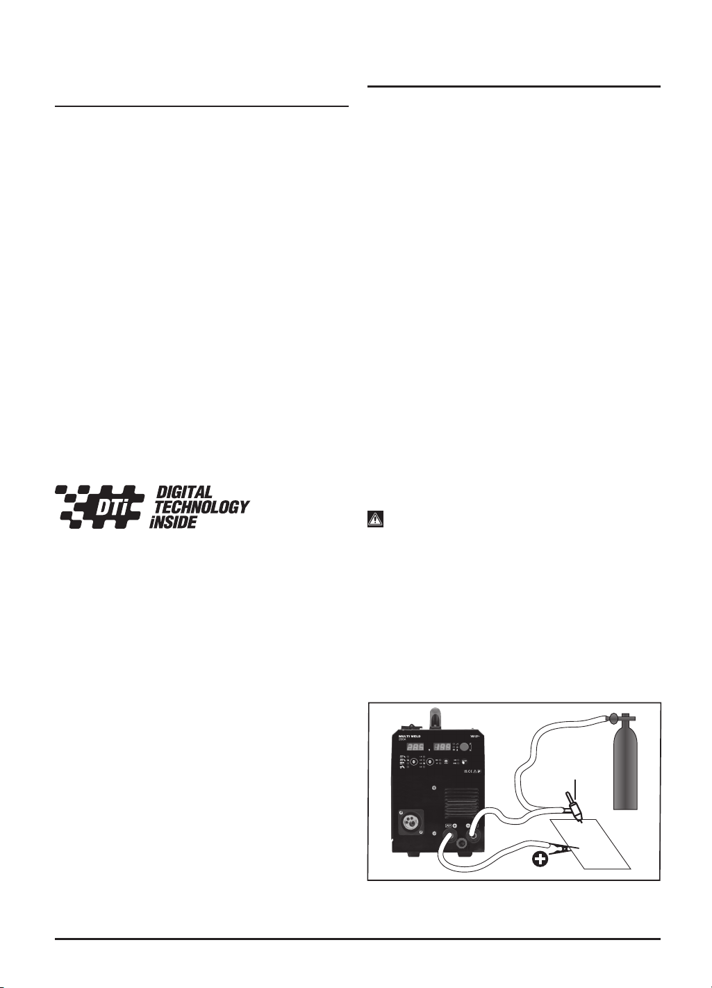
7.3 TIG (TUNGSTEN INERT GAS)
– FIG. 1
A suitable gas supply pressure regulator will be required
to connect the hose to the TIG torch.
To attach the TIG torch (17) to the front panel coupling
(16), plug in and twist to lock.
Attach the earth clamp (19) into the ‘+’ coupling (15).
Caution: For shield gas always use Argon/Argon CO2
mix.
(17)
1
FIG.
Argon
Gas
–
7
–
–
8
–
7.3 MMA (MANUAL METAL ARC)
To attach the electrode holder (20) to the front panel,
insert the plug into positive coupling (15) and twist to
lock.
Attach the earth clamp (19) to the negative coupling
(16) and twist clockwise to lock.
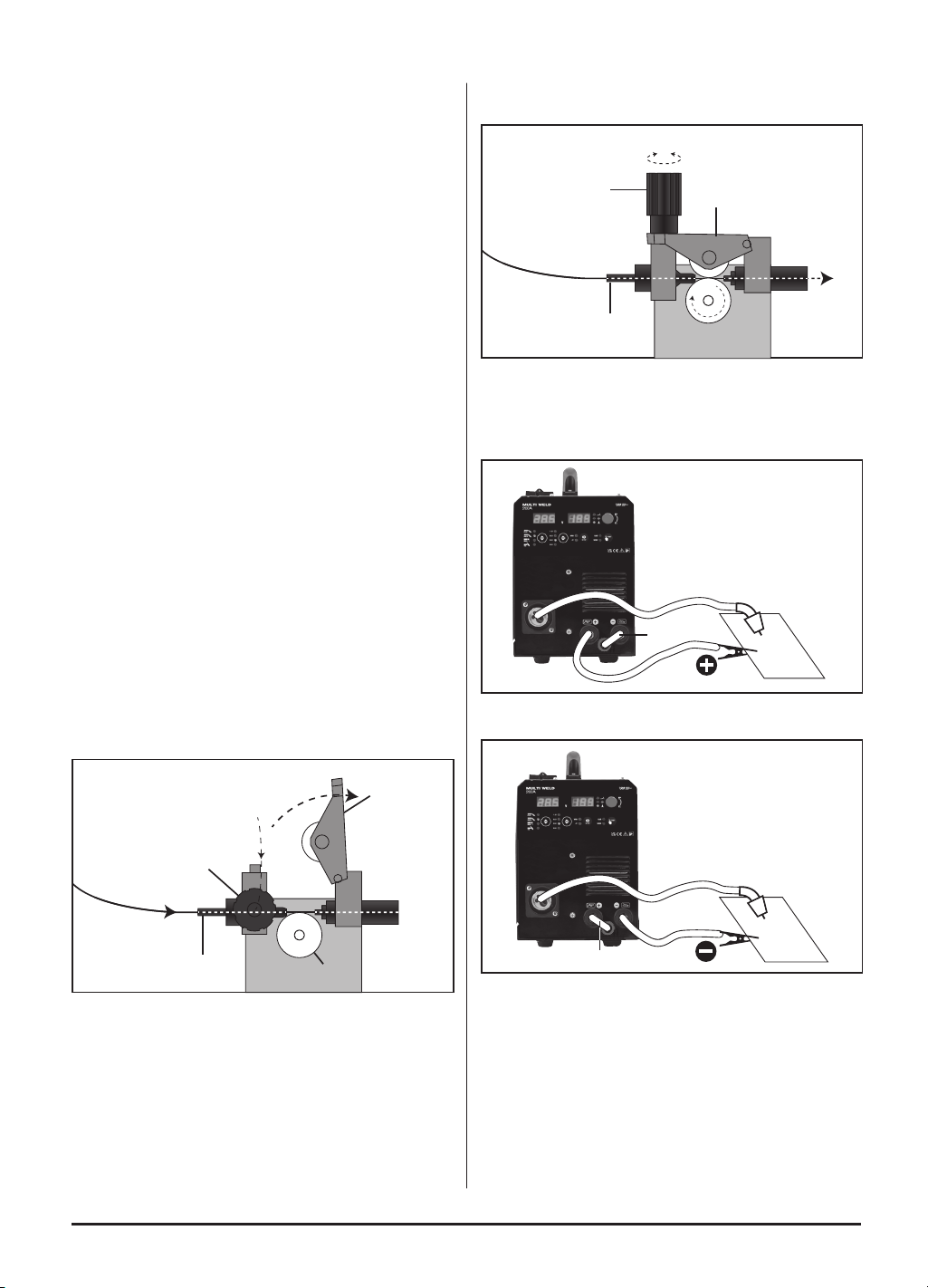
7.4 INSTALLING THE FILLER WIRE
(MIG WELDER) – FIGS. 2 - 6
The welding machine is designed to accept the standard
size drums of wire (5kg).
The welding wire can be either of the ux-cored types
this provides a means of shielding the weld pool from
the atmosphere.
Or non-ux wire with the gas hose connected to the
back of the machine.
Do not let the ller wire become uncoiled or tangled as
this will lead to problems with delivery to the welding
torch.
Select the ller wire suitable for the parent metal and
with a gauge to match the welder specication.
Note: If the welding machine is not regularly used,
remove the wire which is prone to rust and will cause
feed problems next time.
1. Open the side panel.
2. Unscrew the large plastic ring. Sit the reel on to the
hub (24) and make sure the peg locates in the back
of the reel. Ret the large plastic ring.
3. Fit the wire spool so that it feeds off the base of the
reel towards the wire drive unit (25).
4. Pull tensioner (25.1) forward off the tension arm
(25.2), the tension arm (25.2) will spring up out of
the way.
2
FIG.
(25.2)
(25.1)
(25.3)
(25.4)
5. The wire must sit in the appropriate groove for the
wire gauge. The groove size is etched on the side of
the roller. Remove nut to see the groove size that is
NOT in use. The drive roller (25.4) can be removed
from shaft, to change the groove size for appropriate
wire gauge. Unscrew and remove the retaining cap.
6. Pass the ller wire through the guide (25.3) and over
the top of the drive roller, make sure the wire is well
inside the torch liner before closing the arm (25.2)
and tensioner (25.1).
3
FIG.
(25.1)
(25.2)
(25.3)
7. Connect the welding machine to the power supply.
8. Attach the Polarity change plug (14) as illustrated for
either GAS or GASLESS.
FIG.
GASLESS
MIG WELDING
4
(14)
5
FIG.
GAS
MIG WELDING
(14)
9. Press the feed trigger on gun and observe the wire
feed mechanism. If the wire is being fed correctly it
will come out of the swan neck. If it jams you will
need to remove the gas shroud (18.1) and with a
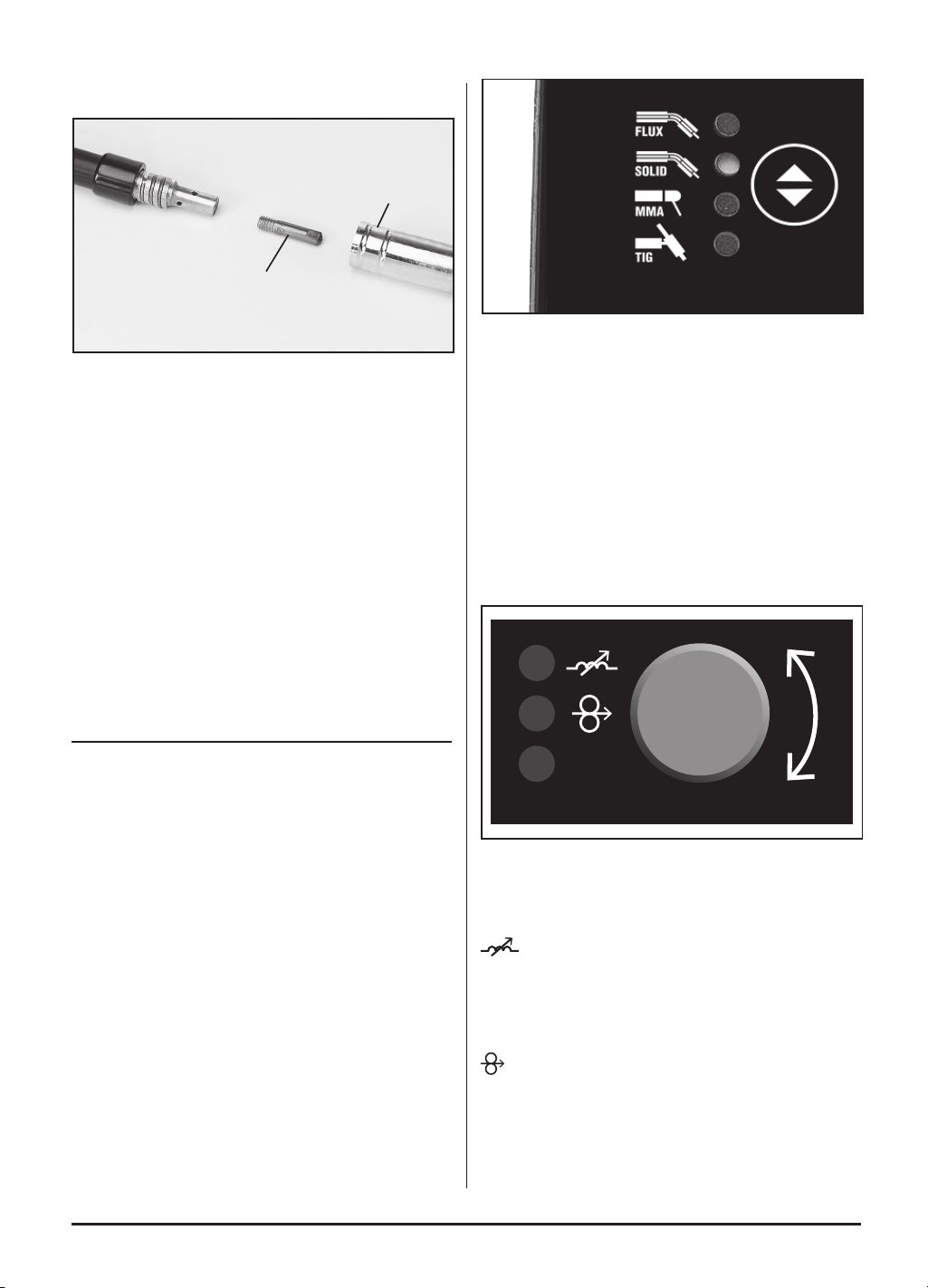
small spanner unscrew and remove the tip (18.2).
Pass the tip over the wire and secure back onto the
swan neck. Do not over tighten. Resecure the gas
shroud and trim the wire back as required.
–
9
–
Note: Ensure the tip size matches the wire size prior to
installing.
6
FIG.
(18.2)
(18.1)
10. If bottled gas is required for the weld it will be tted
via the hose barb (21) on the back.
7.5 NO GAS WELDING PRINCIPLE
For a successful weld joint, the molten metal must be
protected from contaminating gases found in the air.
This is achieved by using a ux cored ller wire. The ux
is produced as the wire melts.
The ux creates a coating over the weld and once
cooled will need to be removed by chipping it off.
If allowed to cool naturally some areas of the ux may
ping off of the weld by themselves due to thermal
contraction for this reason it is recommended that eye
protection is worn.
8. BASIC WELDING
OPERATION
NOTE: Although this machine is medium weight and
portable take care with additional items i.e. gas bottles
etc. Do not manoeuvre over people’s heads.
8.1 WELDING TYPE SELECTION -
SWITCH – FIG.7
• TIG (GTAW) Gas Tungsten Arc Welding.
• MIG (GMAW) Gas Metal Arc Welding.
• MMA ARC welding, stick welding, or (SMAW)
Shielded Metal Arc Welding.
7
FIG.
Note: Welding is a mix of science and art and due to the
complex principles and vast differences in parameters
(ie. Material type, position, condition etc.) That
information is well beyond the scope of this manual.
Draper Tools suggest training be obtained from a third
party or refer to a suitable reference book on the subject
additionally; nothing can beat practice using the welder
on scrap material to get a better understanding.
8.2 CONTROLS – FIG. 8
Parameter Adjustment knob (5): the button is used for
the regulation of:
Wire feed speed, Current, Voltage, Inductance.
A
8
FIG.
(5)
Natural adjustment is for minor regulation, for fast
regulation, press the knob, keep nger unreleased, and
adjust for desired values.
Inductance
The current travelling through an inductance coil creates
a magnetic eld. This magnetic eld creates a current in
the welding circuit that is in opposition to the welding
current. Increasing the inductance will also increase the
arc time and decrease the frequency of short-circuiting.
Wire speed
Wire speed is dependent on material thickness and
welding current. Being able to judge the correct wire
speed based on the sound and quality of the weld will
only come from practice.
• Too fast will result in holes blowing in the weld or the
wire hitting the metal will force the torch backward.
–
10
–
• Too slow will result in the wire burning back to the
torch into a ball and clogging the tip.
VRD.
The VRD function fulls the purpose of drastically
reducing the harm which may result to a person from
inadvertent contact with the electrode during non-
welding pauses.
4T Mode
Press and release the gun/torch trigger to start, weld
without holding the trigger on and stop by pressing and
releasing the trigger again. This is particularly useful
when doing long weld runs.
8.3 MIG WELDING PRINCIPLES – FIGS.
9 – 10
The MIG welding process allows two similar materials to
be fused together without altering the properties of the
material. The electric arc created between the electrode
(the welding wire) and the work piece produces the
required heat for turning the metal into a molten state.
The gas creates a shield around the arc and the molten
metal.
The area to be welded and the earth point must be
clean of grease, dirt, paint and rust. Clean with a wire
brush as necessary. Position the earth clamp as close
as possible to the working area and ensure a tight grip is
achieved.
Select the welding current based on the thickness of the
material. A thick piece will require a high current,
however due to the duty cycle this will effect the welding
time by signicantly reducing it. A thin piece will only
require minimal heat and so the current can be less.
This will allow a longer period of welding. The position of
the torch is critical to the arc and end results.
9
FIG.
10
FIG.
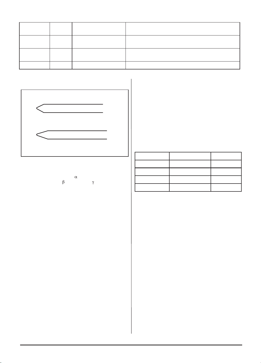
The position of the welding torch is important to achieve
a good quality bead. Position the torch at approximately
35° vertically and 75° horizontally and up to 20mm
distance from the join. 20mm is the maximum that can
be achieved on the maximum setting. Ensure the gas
shroud remains clean of spatter. Likewise and more
importantly the wire feed tip must be kept clean to avoid
the wire becoming blocked or restricted.
Use of an anti-spatter spray (Draper Stock No.05709)
will help keep the end result more tidy.
8.4 TIG WELDER, TUNGSTEN
ELECTRODES - SELECTION &
PREPARATION – FIG. 11
The correct selection of tungsten size and type will
vary for each application dependent upon amperage,
material thickness, equipment and shield gas, however
as a general rule for DC output negative electrode
machines a 1.6mm thorium or cerium oxide tungsten
electrode will sufce.
The selection of the ceramic shroud is based on the
tungsten electrode and should be 4 to 6 times the
tungstens diameter. For example a 1.6mm tungsten
could be used with a No.4 (6.4mm) ceramic shroud, a
No.5 (8.0mm) or at the maximum a No.6 (9.8mm).
There are a variety of different tungsten electrodes
available with the most common categories underlined:
Note: The alloy content shown are a guide but generally
range between 1% to 4%.
Before welding can commence the electrode must be
prepared, i.e. the tip ground to a suitable point.
If using a grinding wheel, a dedicated abrasive wheel
must be used to prevent contamination of the tungsten.
The tip must be ground straight, i.e. perpendicular to the
grinder’s drive spindle.
Note: For DC welding the tip should be ground into a
point to help produce a stable arc.
The general rule is to grind the point’s length to match
the electrodes diameter (A).
However for low amperage/smaller diameter electrodes
the points length should be double the electrodes
diameter (B).
With AC welding you maynd the tip forms itself into a
balled conguration.
11
FIG.
(A)
(B)
Note: During the grinding process thorium alloy
tungsten can release alpha (
) dust particles and in
some instances beta (
) and gamma ( ) particles. Avoid
inhalation as they act as a carcinogen.
In addition to dust protection, safety goggles must be
warn to protect eyes from sparks and debris thrown up
by the grinder.
Selection of the appropriate specication electrode is
important to achieve a good quality weld. Seek guidance
if unsure of selection.
8.5 MACHINE OPERATION
No TIG ller wire is supplied with this machine, however
a list of accessories are displayed in the optional
accessories. Alternatively, consult your local Draper
stockist for further information.
Prepare the joint(s) to be welded. Select the electrode
suitable for the application and insert it into the electrode
holder as described in the manufacturers literature.
The tungsten should extend 3-6mm past the end of
shroud but no greater than the gas shroud diameter.
With the earth clamp, electrode holder and gas bottle
connected, connect the machine to the power supply.
The power display will illuminate as conrmation. Set
the amperage adjustment appropriate to the selected
electrode size.
Secure the earth clamp to a clean sound section of the
parent metal in the vicinity to the intended weld. With all
safety equipment in place and personal protective
clothing on begin welding.
Note: Ensure the gas bottle regulator is open.
Open the torch gas control valve (where tted).
Lower the electrode down toward the parent metal.
Allow the tip of the tungsten to touch the workpiece and
carefully lift again, the arc will be established and
welding can commence.
8.6 ARC WELDING, FILLER ROD
(ELECTRODE) SELECTION – FIG. 12
The correct selection of electrode size and type will vary
for each application dependent upon material thickness,
material type, amperage and equipment, however as a
guide the gures below provide an indication.
MMA Electrode Material Thickness Amp Range
≤1.6mm 1-1.5mm ≤50A
2.0mm 1.2-3mm 45 - 75A
2.5mm 2-5mm 75 - 110A
3.25mm 4-8mm 100 - 150A
With the MMA welding process the arc created between
the work piece and the consumable electrode rod melts
the parent metal and the ller metal in a weld pool.
The electrode’s ux coating reacts during this process
and develops into a shield gas protecting the weld bead.
Part of this reaction leaves a trail of slag which solidies
behind the weld pool protecting the weld as it cools.
The most common varieties of electrodes are cellulosic,
rutile and basic, the latter two being the most general
purpose.
Selection of the appropriate specication electrode is
important to achieve a good quality weld. Seek guidance
if unsure of selection.
–
11
–
Colour Code
Band
Content Composition Comments
White 0.7-0.9% Zirconium Oxide
contamination resistance.
Predominantly used for AC welding due to its resistance to
tungsten spitting and ability to retain a rounded prole tip.
Red 1.8-2.2% Thorium Oxide Long life DC welding tungsten alloy providing improved
ignition properties and a stable arc. See HSE guidelines.
Grey 1.8-2.2% Cerium Oxide Capable of AC/DC welding with reduced slag deposits.
–
12
–
12
FIG.
8.7 MMA/ARC MACHINE OPERATION
- FIG. 13
Prepare the joint(s) to be welded.
Select the electrode suitable for the application and
insert into the electrode holder (20) while pressing lever
(20.1).
With the earth clamp and electrode holder connected,
connect the machine to the power supply. The power
display will illuminate as conrmation. Set the amperage
appropriate to the selected electrode size.
Secure the earth clamp to a clean sound section of the
parent metal in the vicinity to the intended weld.
With all safety equipment in place and personal
protective clothing on begin welding.
Lower the electrode down toward the parent metal and
strike the arc.
13
FIG.
(20)
(20.1)
8.8 DIRECTION OF WELD – FIG. 15
Strike the initial arc perpendicular to the parent metal
before moving the electrode holder in the direction of
travel 20-30° (Z,Y axis) and tilt it 20-30° (Z,X axis).
Maintain a constant gap between the electrode tip and
the weld pool of approximately 1 to 1.5 times the
diameter of the electrode for a stable arc. This machine
is equipped with two additional features ‘Arc Force’ and
‘Anti-Stick’ to ensure smooth welding and reduce the
instances of the electrode becoming stuck to the parent
metal.
Z
-Z
-X-Y
XY
Direction
of weld
14
FIG.
Denition:
ARC FORCE
The machine will automatically create a specic
overpower when the electrode is too near, forcing it back
to help avoid the risk of sticking.
Denition:
ANTI-STICK
The machine will automatically reduce the intensity of
the current in order to aid quick and simple separation of
the electrode and parent metal.
The position of the electrode is critical to the arc and the
end result. Achieving a good weld will take practice.
For more detailed information refer to a welding book
and/or seek training on the subject.
Use of an anti-spatter spray Draper stock No.05709 will
help to achieve a cleaner nished weld. This welding
power source has a maximum material thickness
capability of 5mm.
8.9 THERMAL CUT-OUT
If welding for extended periods the thermal cut-out will
activate prohibiting use of the machine until sufciently
cool.
Attention: After completion of any welding task leave
the unit connected to the power supply for a sufcient
period to allow the cooling fan to continue working.
8.10 DEFINITION:
DUTY CYCLE:
Duty Cycle is a percentage of 10 mins. in which a
machine can operate at a rated load without overheating
and interruption from the thermal cut-out device.
Example: 150A @ 30% Duty factor
150A welding for 3 minutes
7 minutes down time

–
13
–
Example: 95A @ 100% Duty factor
95A continuous welding
To increase the operation time, reduce the amperage.
Note: The heating tests have been carried out at
ambient temperature and the duty cycle (duty factor) at
20°C has been determined by simulation
Denition:
ARC WELDING:
Fusion welding in which heat for welding is obtained
from an electric arc.
Denition:
MANUAL METAL ARC (MMA welding):
Also known as SMAW (Shielded metal arc welding).
Metal-arc welding† with straight covered electrodes of a
suitable length and applied by the operator without
automatic or semi-automatic means of replacement. No
protection in the form of gas from a separate source is
applied to the arc or molten pool during welding.
†Arc welding using a consumable electrode.
Denition:
TUNGSTEN INERT-GAS (TIG welding)
Also known as GTAW (Gas tungsten arc welding)
Gas-shielded arc welding using a non-consumable pure
or activated tungsten electrode where the shielding is
provided by a shroud of inert gas.
Note: Although the tungsten electrode is classed as
non-consumable compared to the ller rod type
electrode it will be consumed by the TIG process and
require re-sharpening and eventually replacing.
Denition:
METAL INERT-GAS (MIG welding)
Also known as GMAW (Gas metal arc welding)
A welding process in which an electric arc forms
between a consumable wire electrode and the
workpiece metal(s), which heats the workpiece metal(s),
causing them to melt, and join. Along with the wire
electrode, a shielding gas feeds through the welding
gun, which shields the process from contaminants in the
air.
–
14
–
10. MAINTENANCE
10.1 MAINTENANCE
Regular inspection and cleaning reduces the necessity
for maintenance operations and will keep your tool in
good working condition.
Warning: Remove the plug from the power supply.
Periodically the welder must be checked as detailed
below.
• Check the torch cable and ground cable connections.
• Clean the contact tip and the gas shroud with an iron
brush. Replace if worn.
• Clean the outside of the welder with a damp cloth.
• Every time the wire spool is replaced:
• Check the alignment, cleanliness and state of wear
of the wire roll.
• Remove any metal powder deposited on the wire
feeder mechanism and then dry with compressed air.
• Occasionally test to ensure the thermal cut-out
device is operating correctly, i.e. weld for an
extended period or on a maximum duty cycle.
• Check the condition of the warning labels.
• Replace any worn parts.
• If the replacement of the supply cord is necessary,
this has to be done by the manufacturer or his agent
to avoid a safety hazard.
The welder must be correctly ventilated during tool
operation. Avoid blocking the air inlets and vacuum the
ventilation slots regularly.
Do not use solvents or fuels to clean the product. When
not in use, store the product in a safe, dry place.
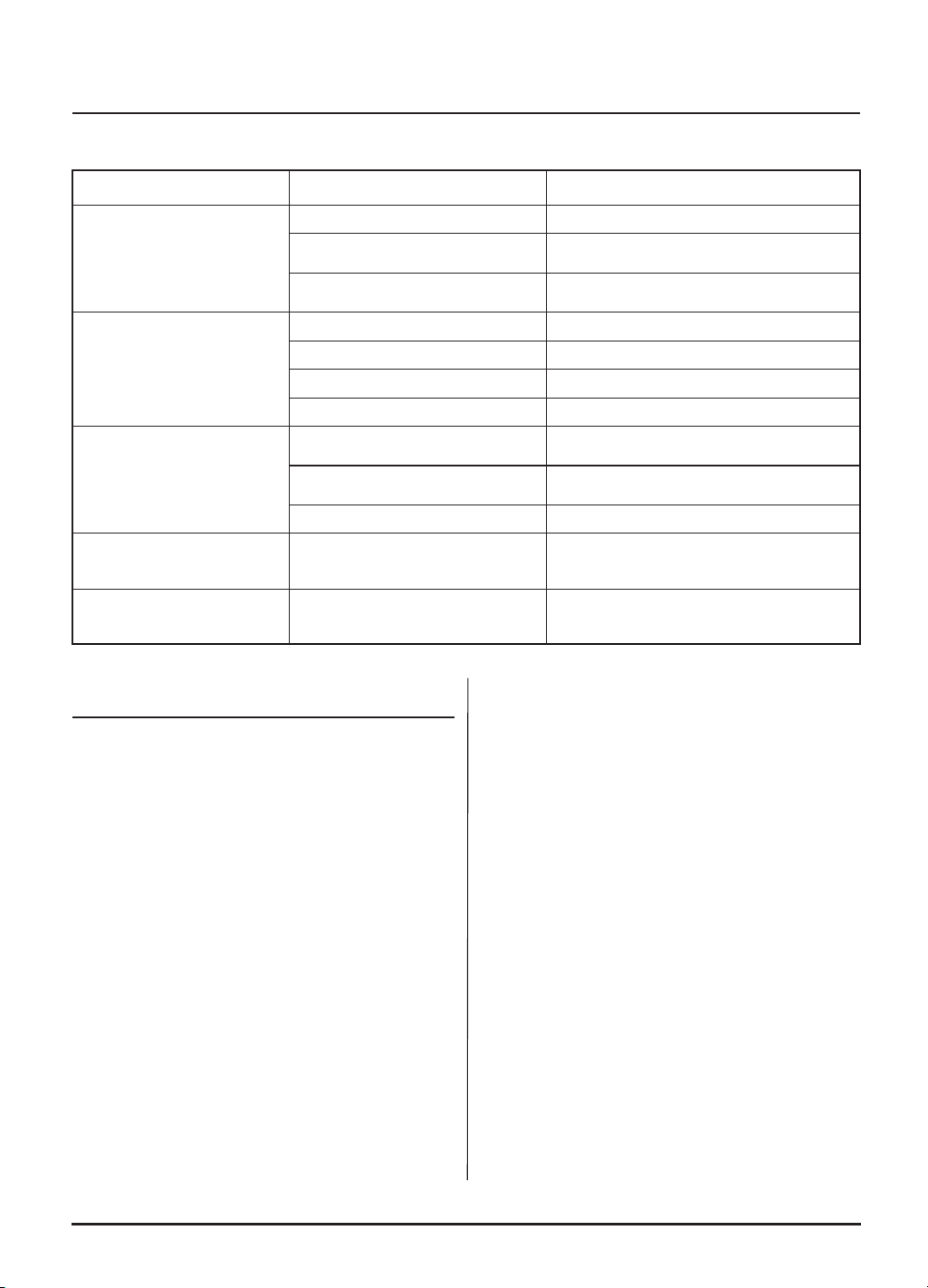
9. TROUBLESHOOTING
9.1 TROUBLESHOOTING
WARNING: For your own safety, turn the switch off and remove the plug from the power supply socket.
PROBLEM POSSIBLE CAUSE REQUIRED ACTION
Wire not feeding despite
wire feed pulley turning.
Dirty current nozzle (contact tip). Clean.
May be an obstruction at the
contact tip.
Remove obstruction.
Too low clamping pressure of the
wire feed pulley.
Increase the clamping pressure.
Interrupted or disruptive
wire supply.
Damaged current nozzle. Replace.
Burnt current nozzle. Replace.
Dirty driving gear torch liner. Clean.
Cut on worn driving gear. Replace.
Electric arc turned off.
Poor contact between earth
clamp and part to be welded.
Tighten the pliers and check them,
remove paint and rust.
Short circuit between current
nozzle and gas supply pipe.
Clean or replace the current and gas
nozzle, remove dirt, paint and rust.
Too loose current nozzle. Tighten the current nozzle rmly.
Porous welded joint.
No gas, too little gas or wrong
gas.
Achieved via gas regulator ow
adjustment assuming gas bottle has
enough pressure.
Welder suddenly stops
working after longer
operation.
Welder has overheated due to
too long use and the thermal
protection has activated.
Let the welder cool down.
IMPORTANT: Please note all repairs/service should be carried out by a qualied person.
–
15
–
11. WARRANTY
11.1 WARRANTY
Draper tools have been carefully tested and inspected
before shipment and are guaranteed to be free from
defective materials and workmanship.
Should the tool develop a fault, please return the
complete tool to your nearest distributor or contact:
Draper Tools Limited, Chandler’s Ford, Eastleigh,
Hampshire, SO53 1YF. England.
Telephone Sales Desk: +44 (0)23 8049 4333 or:
Product Helpline +44 (0)23 8049 4344.
A proof of purchase must be provided.
If upon inspection it is found that the fault occurring is
due to defective materials or workmanship, repairs will
be carried out free of charge. This warranty period
covering labour is 12 months from the date of purchase
except where tools are hired out when the warranty
period is 90 days from the date of purchase. This
warranty does not apply to any consumable parts, any
type of battery or normal wear and tear, nor does it
cover any damage caused by misuse, careless or
unsafe handling, alterations, accidents, or repairs
attempted or made by any personnel other than the
authorised Draper warranty repair agent.
Note: If the tool is found not to be within the terms of
warranty, repairs and carriage charges will be quoted
and made accordingly.
This warranty applies in lieu of any other warranty
expressed or implied and variations of its terms are not
authorised.
Your Draper warranty is not effective unless you can
produce upon request a dated receipt or invoice to verify
your proof of purchase within the warranty period.
Please note that this warranty is an additional benet
and does not affect your statutory rights.
Draper Tools Limited.
12. DISPOSAL
12.1 DISPOSAL
– At the end of the machine’s working life, or when it
can no longer be repaired, ensure that it is disposed
of according to national regulations.
– Contact your local authority for details of collection
schemes in your area.
In all circumstances:
• Do not dispose of power tools with
domestic waste.
• Do not incinerate.
• Do not dispose of WEEE* as unsorted
municipal waste.
* Waste Electrical & Electronic Equipment.

Contact Details
Draper Tools
Draper Tools Limited
Hursley Road
Chandler’s Ford
Eastleigh
Hampshire
SO53 1YF
UK
Website: drapertools.com
Email: [email protected]
Product Helpline: +44 (0) 23 8049 4344
Telephone Sales Desk: +44 (0) 23 8049 4333
General Enquiries: +44 (0) 23 8026 6355
General Fax: +44 (0) 23 8026 0784
Service / Warranty Repair Agents
For aftersales servicing or warranty repairs, please contact the Draper Tools Product
Helpline for details of an agent in your area.
© Published by Draper Tools Limited
Delta International
Delta International BV
Oude Graaf 8
6002 NL
Weert
Netherlands