Loading ...
Loading ...
Loading ...
ERROR CODES AND PROBLEM SOLVING
PAGE 54
ENGLISH
Checking the Compressor Windings
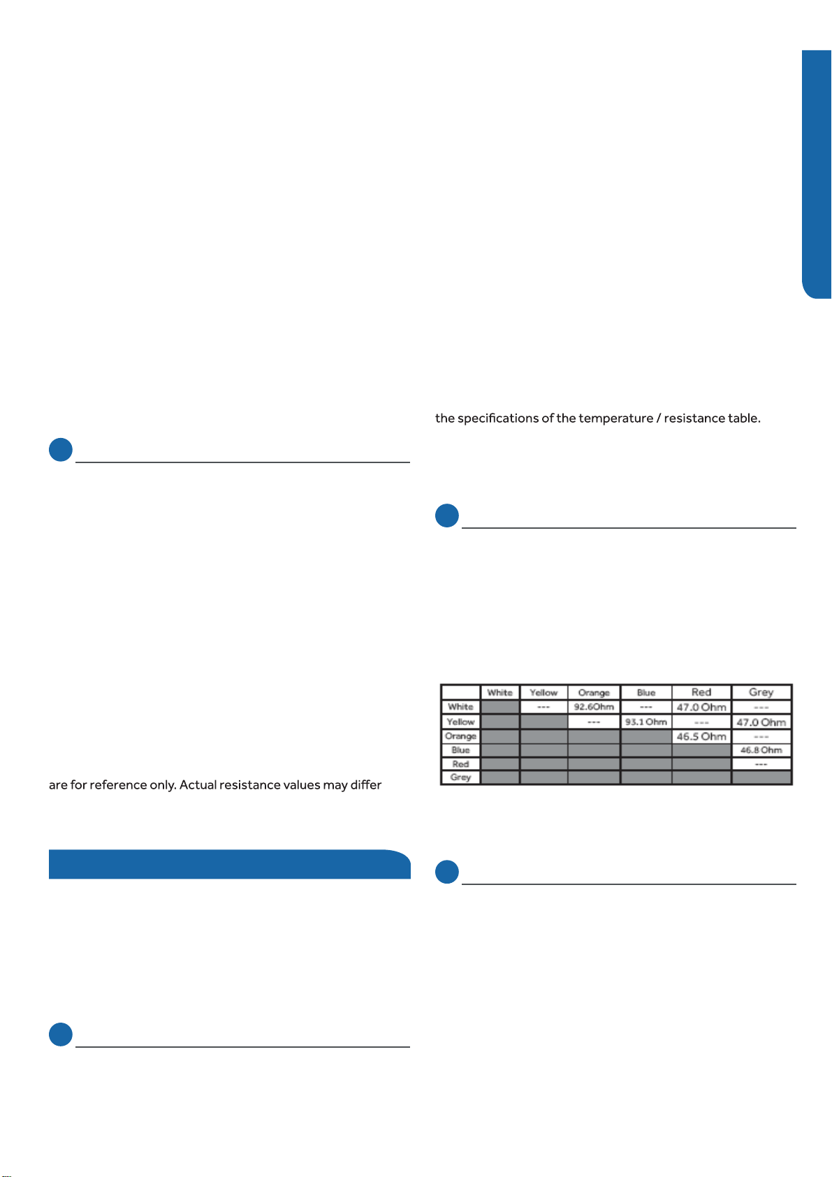
Checking the Up/Down Stepper Motors
Checking the Left/Right Stepper Motors
Checking Indoor Unit Components
Checking the Indoor Unit Sensors
wiring and connections to the PFC Reactor as well as the PFC
Reactor itself. Repair or replace as necessary.
Step 3
Reconnect the wiring to the module board at the conclusion
of the test.
Step 1
Disconnect the Socket Protect plug from the control
board connector for this test. Failure to do so may provide
inaccurate readings.
Step 2
Using an ohmmeter, check the resistance value of the Socket
Protect component. The resistance reading should be 0
Ohms. If it is not, replace the component.
Step 3
Re-seat the plug on the connector at the conclusion of the
test.
Step 1
Disconnect wiring from terminals U (black wire), V (white
wire), and W (red wire) of the power module board.
Step 2
Using an ohmmeter, check the resistance value of the
compressor windings. Measure between wires U (black wire)
and V (white wire), U (black wire) and W (red wire), and V
(white wire), and W (red wire).
The resistance value of the windings should be balanced
(equal). If the resistance values are not equal, verify the
wiring and connections to the compressor as well as the
compressor itself. Repair or replace as needed.
Step 3
Reconnect the wiring to the module board at the conclusion
of the test.
NOTE: Component resistance readings shown in this section
based on model being tested.
Testing of the following components requires the use of an
ohmmeter and temperature probe (Temperature probe is
used during sensor testing only).
NOTE: When using the test probes, probe the back or side
contacts of the plug to obtain the reading. Do not try to
probe the connector end of the plug as this may damage the
contacts of the plug.
NOTE: Use respective temperature / sensor chart for sensor
type being tested.
Coil sensor
Ambient sensor
Step 1
Disconnect the sensor plug from the control board for this
test. Failure to do so may provide inaccurate readings.
Step 2
Using a temperature probe, determine the temperature of
the sensor being tested.
Step 3
Using an ohmmeter, check the resistance value of the sensor.
Step 4
Referring to the temperature / resistance table for the sensor
being checked, verify the resistance value corresponds to the
temperature checked in Step 2.
Replace the sensor if the reading is open, shorted, or outside
Step 5
Re-seat the plug on the connector at the conclusion of the
test.
Step 1
Disconnect the Up/Down Stepper Motor plug from the
control board connector for this test. Failure to do so may
provide inaccurate readings.
Step 2
Refer to the chart shown below for plug pin combinations and
resistance values.
Step 3
Re-seat the plug on the connector at the conclusion of the
test.
Step 1
Disconnect the Left Stepper Motor plug from the control
board connector for this test. Failure to do so may provide
inaccurate readings.
Step 2
Refer to the chart shown below for plug pin combinations and
resistance values.
Loading ...
Loading ...
Loading ...