................................................................................................. 3
..................................................................................... 7
......................................................................................
13
......................................................................................................... 19
............................................................................................................. 25
.............................................................................................. 56
Error codes and Troubleshooting
System Specifications
..................................................................................... 27
.................................................................................... 83
................................................................................. ..... 89
.........................................................................................................
95
............................................................................................................. 103
.............................................................................................. 133
Error codes and Troubleshooting
System Specifications
..................................................................................... 104
INDOOR AW09TE1VHA AW12TE1VHA AW09TE2VHA AW12TE2VHA AW18TE2VHA AW24TE2VHA ASYW09CRAWA ASYW12CRAWA ASYW09CRDWA ASYW12CRDWA ASYW18CRDWA ASYW24CRDWAOUTDOOR1U09TE1VHA 1U12TE1VHA 1U09TE2VHA 1U12TE2VHA 1U18TE2VHA 1U24TE2VHA ASH109CRAWA ASH112CRAWA ASH118CRDWA ASH124CRDWAINDOOR MODELS:1U09TE1VHA, U12TE1VHA, U18TE2VHA, 1U24TE2VHA, ASH109CRAWA, ASH112CRAWA, ASH118CRDWA, ASH124CRDWAAW09TE1VHA, AW12TE1VHA, AW18TE2VHA, AW24TE2VHA, ASYW09CRAWA, ASYW12CRAWA, ASYW18CRDWA, ASYW24CRDWA OUTDOOR MODELS:INDOOR MODELS:1U09TE2VHA, 1U12TE2VHA, ASH109CRDWA, ASH112CRDWAAW09TE2VHA, AW12TE2VHA, ASYW09CRDWA, ASYW12CRDWA OUTDOOR MODELS:

[
This page intentionally left blank.]

PAGE 3
INTRODUCTION
Introduction
Safety Precautions ........................................................................................4
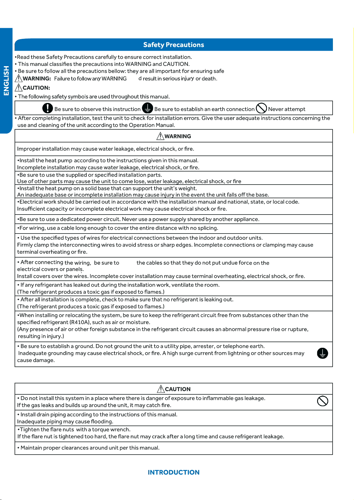
Warnings and Cautions ....................................................................................4
Introduction to System ....................................................................................5
................................ ..........................5
System Fundamentals.......................................................................................5
Table of Contents
PAGE 4
Failure to follow any CAUTION may in some cases result in grave consequences.
coul
route
PAGE 5
INTRODUCTION
Introduction to System
Single Zone Ductless Split System Heat Pumps feature a wall
●
mounted indoor fan/evaporator unit that receives refrigerant
from an inverter driven variable speed outdoor condensing
unit. The system operation is controlled with a remote
control.
The outdoor unit features a variable speed rotary
compressor, EEV metering device and DC fan motor. These
systems use R410A refrigerant and PVE oil. The outdoor units
●
are 115 volt for old models 9K /12K, and 208/230 volt rated
systems for new models 9K/12K and 208/230 volt for 18K/24K.
They come factory charged
piping.
The indoor units are wall mounted. They feature a DC
blower motor and a DC louver motor. The unit has a room
temperature sensor and an evaporator tube temperature
sensor. The wall unit is powered by voltage from the outdoor
unit.
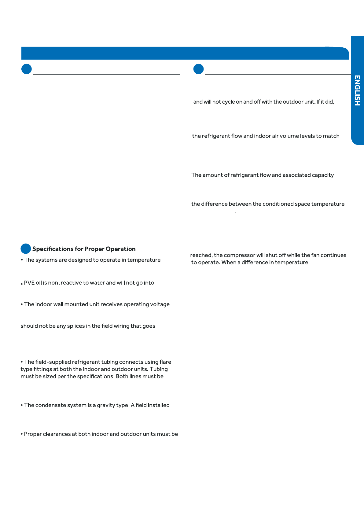
hydrolysis. There is no need to add a refrigeration drier
when servicing or installing this system.
and communication data signals on #14 AWG wire that
connects between the indoor and outdoor units. There
between terminals 1, 2, 3 and 4. A splice in these wires may
cause the system to lose communication between the
indoor and outdoor units. The system will then display an
error code E7.
insulated. The only method of checking charge or adjusting
charge is by weight method explained in this manual (no
exceptions).
condensate pump may be added to the system. Always
follow the manufacturer’s installation instructions when
installing a condensate pump.
●
maintained. Improper clearances cause incorrect refrigerant
pressures and coil freezing.
System Fundamentals
The indoor unit will sense room temp
●
erature at the point
where the wall unit is installed. The indoor fan will run
continuously when placed in heating or cooling mode
room temperature could not be sensed or maintained.
Introduction
The inverter compressor system in the outdoor unit will vary
the comfort requirement inside the conditioned space. If an
abnormal condition is detected by the system’s sensors, the
system has the ability to take reactive measures.
generated by the system will be determined by how fast the
system’s variable speed rotary compressor is pumping. The
compressor operating speed is determined by
and the set point
If a large amount of capacity is needed, the compressor will
operate at a high speed. As the need for capacity
reduces and the temperature of the room nears set point,
the compressor will slow down. When set point has been
is sensed between the set point and room, the compressor
will restart at a new calculated speed.
If a system sensor determines there is a need to adjust
the frequency signal to prevent a system malfunction,
the compressor frequency may be over ridden and a new
frequency established. It should be noted that the frequency
signal level that is sent to the compressor cannot be
determined by a servicing technician.
In this manual, system components, operation, sensor
functions, and diagnostic procedures will be explained in
greater detail.
The indoor unit can be set from 60°F-86°F (16°C-30°C)
during both cooling and heating.
for up to 25 ft. of interconnecting

INTRODUCTION
PAGE 6
>7KLVSDJHLQWHQWLRQDOO\OHIWEODQN@

OUTDOOR UNIT CONTROLS and COMPONENTS PAGE 7
ENGLISH
Outdoor Unit Controls & Components
Table of Contents
Unit Introduction ................................................................................................................................................................8
..................................... 8
9.............................................................................................................................................................. draoB lortnoC niaM
.................................................. 10
Reactor ............................................................................................................................................................................ 10
Compressor ..................................................................................................................................................................... 10
01........................................................................................................................................................................... rotoM naF
Discharge Temperature Sensor ........................................................................................................................................ 11
Defrost Temperature Sensor ............................................................................................................................................ 11
11............................................................................................................................................ rosneS erutarepmeT tneibmA
Suction Line Temperature Sensor ..................................................................................................................................... 11
4-Way Valve .....................................................................................................................................................................12
Electronic Expansion Valve ............................................................................................................................................... 12
Accumulator .................................................................................................................................................................... 12
Filters ............................................................................................................................................................................... 12
OUTDOOR UNIT CONTROLS and COMPONENTS
PAGE 8
ENGLISH
Outdoor Unit Introduction
1
2
3
4
5
6
7
8
9
10
11
12
13
14
15
8
4
6
11
12
13
14
1
3
2
7
5
9
10
15
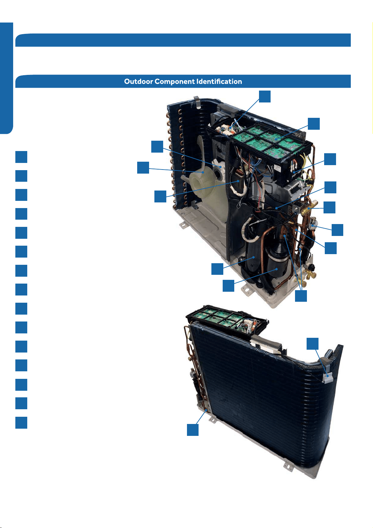
The outdoor unit has two circuit boards, an Inverter Power Module (IPM) that drives the compressor and a main control
board (PCB) that manages system functions and inverter calculations. Temperature Sensors monitor key temperatures
throughout the system to manage operational decisions.
4-Way Valve
Accumulator
Compressor
Defrost Temperature Sensor
Discharge Temperature Sensor
Electronic Expansion Valve
Refrigerant Strainers
Ambient Temperature Sensor
Fan Motor
Power Factor Reactor
Suction Line Temperature Sensor
Terminal Block
PCB
IPM
Fan Blade
OUTDOOR UNIT CONTROLS and COMPONENTS PAGE 9
ENGLISH
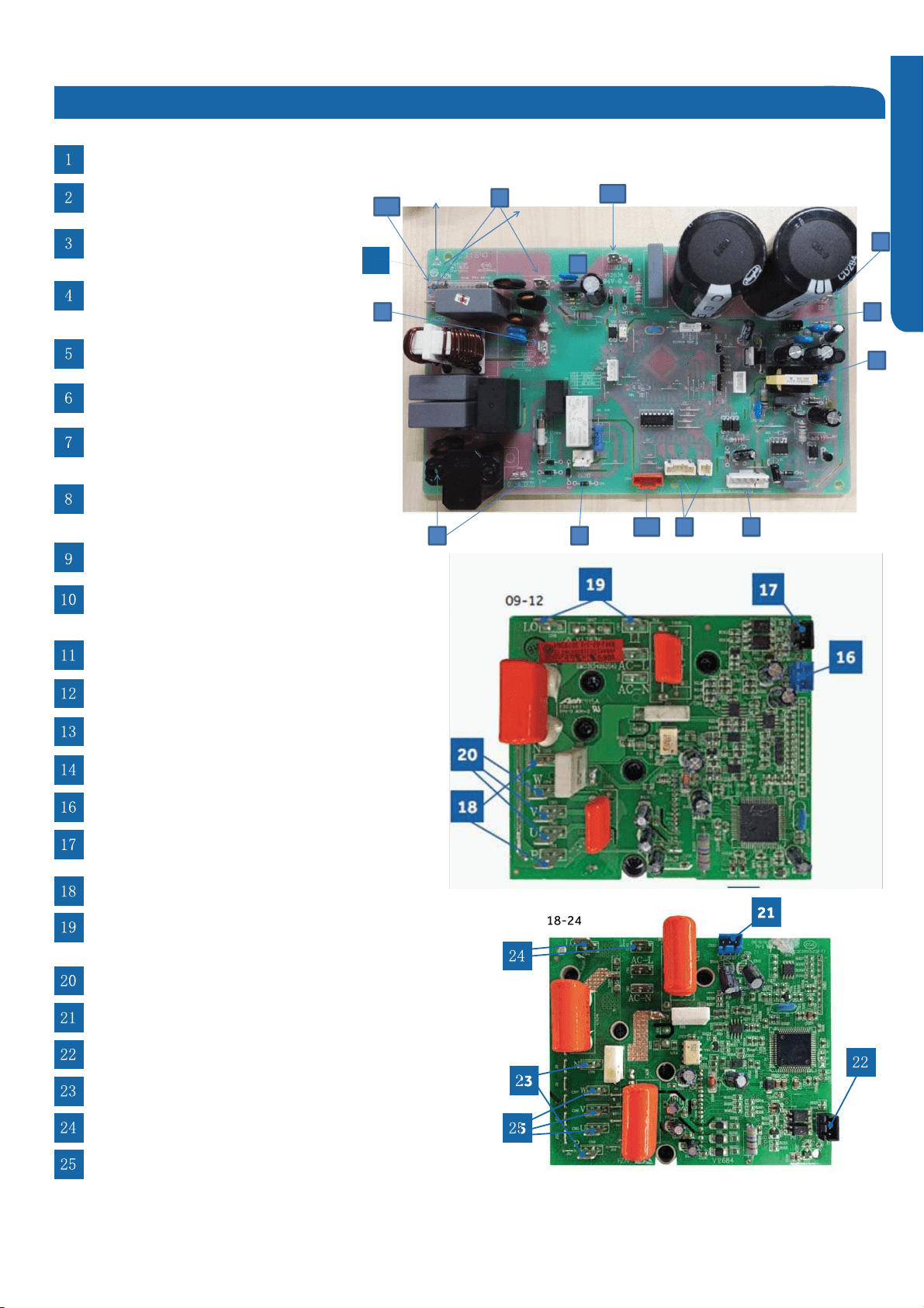
PCB
PCB (1)
CN3-Connector for ground
CN10 (09k and 12k), CN11 (18k and 24k) -
4-way valve connections
CN8 and CN9 (09k and 12k), CN9 and
CN10 (18k and 24k) - 230 VAC output from
the PCB to the IPM
18-24
CN23 (09k and 12k) and CN24 (18k and 24k) -
5-G-15 VDC communication connection
between the PCB and the IPM
CN1,CN2-Connector for power N and L
CN18 and CN20 (09k and 12k), CN17, CN21,
and CN47 (18k and 24k) - Connectors for
thermistors
CN22 (09k and 12k), CN23 (18k and 24k) -
5-G-15 VDC connections for power to the IPM
CN24 and CN26 (09k and 12k), CN25 and CN28
(18k and 24k) - 310+ VDC connection from the IPM
CN21 (09k and 12k), CN22 (18k and 24k) -
Connection for the fan motor
CN10-09k and 12k IPM:5-G-15 VDC power from the PCB
CN11 - Connector for the 5-G-15 VDC communication
signal between the PCB and the IPM
P(CN1), N(CN5)- 310+ VDC power to the PCB
LI (CN7), LO(CN6) - Power filter reactor connections
CN2,CN3,CN4-Connector for the
U, V, and W compressor wire connections
61211 7
RV1,RV2,RV3 ,RV4 Varistor
1
2
3
5
4 6 7
8
9
10
11
PCB(3)(Module PCB for 18-24K)
CN10 - 5-G-15 VDC power connection from the PCB
CN11 - 5-G-15 VDC communication connection with the PCB
P(CN8), N(CN9)- 310+ VDC power connection to the PCB
LI (CN3), LO(CN4) power filter reactor
CN5,CN6,CN7-Compressor U, V, and W wiring connections
12
14
CN4 (09k and 12k) and CN36 (18k and 24k) -
Communication connection between
the indoor and outdoor units
CN16 (09k and 12k), CN15 (18k and 24k) - EEV connections
FUSE 1 (25A, 250V) ; FUSE 2 (3.15A ,250V)
LED1 - Steady flash indicates normal operation
while intermittent flashes are error codes
OUTDOOR UNIT CONTROLS and COMPONENTS
PAGE 10
ENGLISH
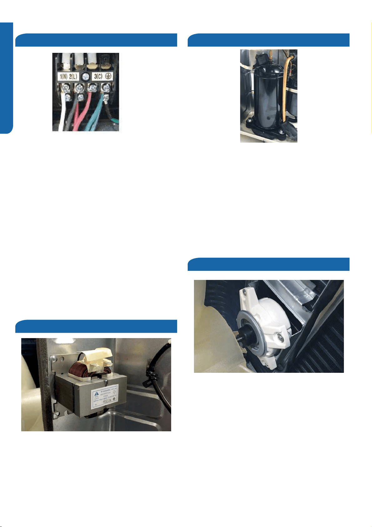
Terminal Block
Power Factor Reactor
Compressor
Fan Motor
The 18K and 24K units are 208/230 volt single phase. The
9K and 12K units are 120 volt. All models use terminals 1
and 2 as incoming power wiring. Number 3 is the
communication terminal and the 4th terminal is the ground
connection. Be sure to match this wiring with the indoor
unit terminals.
External accessories such as a condensate overflow switch
should break the number 2 (line) terminal.
The indoor unit is powered from the same source as the
outdoor section and is connected by using 14/4 AWG
copper wire.
There should be no splices in the wiring between the indoor
and outdoor unit.Splices may create a loss of communication
and generate an E7 error code.
The Reactor is an inductive filter that will aid in correction of
electrical power factor influence of inverter capacitance. It is
unlikely to ever have an electrical failure of this component.
The Reactor is electrically connected to the IPM on terminals
CN6 and CN7 (09k and 12k), or CN3 and CN4 (18k and 24k)..
The compressor is a three phase DC inverter-driven rotary.
The compressor is capable of variable speed operation.
The operating frequency will be determined by the difference
between set point and room emperature.
The compressor is electrically connected to the Module
Board on terminal connections CN-2, CN-3 and CN-4.
The compressor has an internal temperature overload that
will open if the compressor becomes too hot. Additional
protection of the compressor will be provided by the
Compressor Discharge Temperature Sensor and Suction
Line Temperature Sensor.
The fan motor is a variable speed DC motor,The required
motor speed is calculated by the Main Control Board.
The motor is electrically connected to the PCB via
CN21 (09k and 12k), or CN22 (18k and 24k).
In COOL MODE , the motor will slow down as outdoor air
temperature falls. In HEAT MODE, the motor will increase
speed as the outdoor air temperature falls.
OUTDOOR UNIT CONTROL S and COMPONENTS PAGE 11
ENGLISH
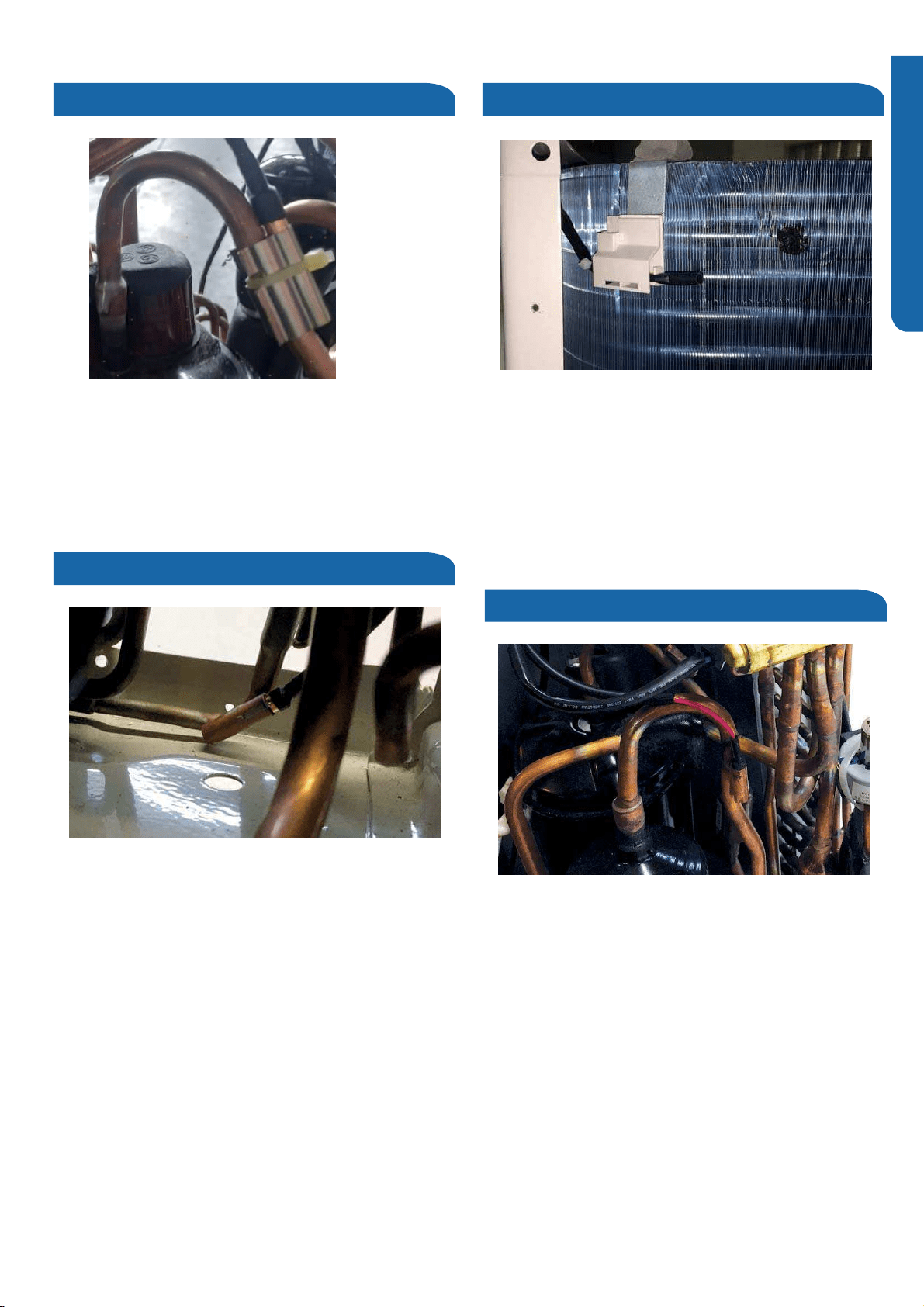
Discharge Temperature Sensor
Defrost Temperature Sensor
Ambient Temperature Sensor
Suction Line Temperature Sensor
The Discharge Sensor is a negative coefficient thermistor
that senses the temperature of the compressor hot gas.
The PCB will make inverter speed changes in response
to input from this device.
This sensor connects to the PCB at CN20 (09k and 12k),
or CN17 (18k and 24k)..
The Defrost Temperature Sensor is a negative coefficient
thermistor that will change resistance in response to outdoor
coil temperature changes. The Main Control Board monitors
the temperature of the outdoor coil to determine when a
defrost cycle is necessary.The sensor alsomonitors outdoor
coil temperature during defrost cycles todetermine termination
conditions.
This sensor connects to the Main Control Board at PLUG CN-
20.
The Ambient Sensor is a negative coefficient thermistor that
will change resistance in response to temperature changes.
The PCB monitors the temperature of the outdoor air to
determine outdoor fan speed requirements and compressor
speed. The sensor also plays a role in calculation of required
defrost conditions.
This sensor connects to the PCB at CN20 (09k and 12k),
or CN19 (18k and 24k)..
The Suction Line Temperature Sensor is a negative
coefficient thermistor that senses.the temperature
of the suction line to determine EEV orifice size,
maintaining in an attempt to maintain proper operating
superheat.
This sensor connects to the PCB at CN18 (09k and 12k),
or CN47 (18k and 24k).
OUTDOOR UNIT CONTROS and COMPONENTS
PAGE 12
ENGLISH
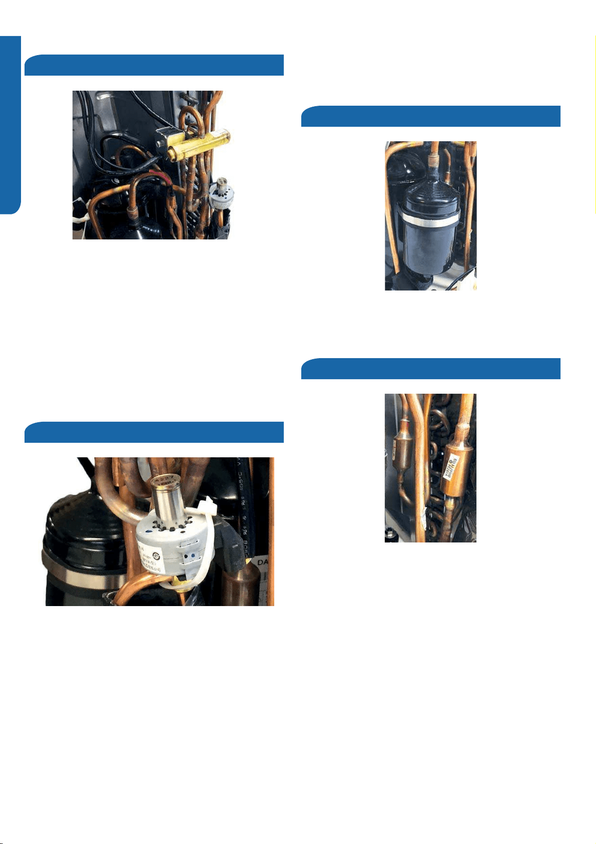
4-Way Valve
Electronic Expansion Valve
Accumulator
Refrigerant Strainers
The 4-Way Valve redirects the flow of refrigerant to reverse the
functions of the indoor and outdoor coils. When de-energized
in COOL MODE, the valve will direct the refrigerant hot gas to
the outdoor coil.When energized in HEAT MODE, the valve will
direct the hot gas to the indoor coil.
The direction of flow is changed by an electrical solenoid that
moves an internal slide mechanism.
The 4-Way Valve is electrically connected to the PCB at
CN10 (09k and 12k), or CN11 (18k and 24k).
The valve consists of an electrical operator and a valve
body with internal variable size orifice. When operating,
the PCB will send pulses of voltage to the electrical operator.
The operator will then magnetically move the position
of the metering orifice pin to vary the flow of refrigerant.
The pin position is determined from the Suction Line
Temperature Sensor input, which will change the flow
of refrigerant to maintain proper operating superheat.
During COOL MODE operation, the valve meters low
pressure refrigerant to the indoor coil. During HEAT MODE
operation, the valve meters low pressure refrigerant to the
outdoor coil.
The Accumulator is located in the suction line at the entrance
to the compressor.The accumulator helps prevent liquid
refrigerant from entering the compressor .
The system has debris-catching strainers that protect internal
system components from contaminants.The straineris
a permanent part that is not typically replaced.

INDOOR UNIT CONTROS and COMPONENTS PAGE 13
ENGLISH
Indoor Unit Controls and Components
Table of Contents
Unit Introduction ...................................................................................................................................................................... 14
................................................................................................................................................ 14
Control Board ............................................................................................................................................................................ 15
Terminal Block .................................................................................................................................................................. 16
Display ............................................................................................................................................................................. 16
Ambient Temperature Sensor .......................................................................................................................................... 16
Piping Temperature Sensor .............................................................................................................................................. 16
Louver Motor ................................................................................................................................................................... 17
Fan Motor ......................................................................................................................................................................... 17
Emergency Button ........................................................................................................................................................... 17
INDOOR UNIT CONTROLS and COMPONENTS
PAGE 14
ENGLISH
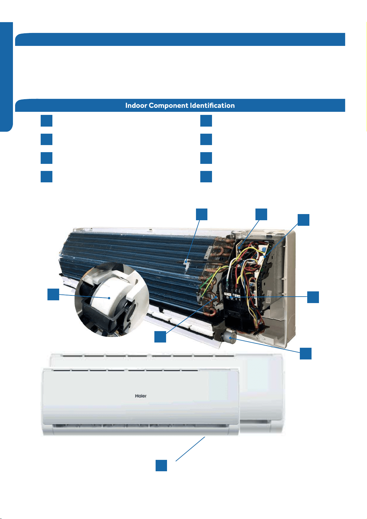
Indoor Unit Introduction
Display
Fan Motor
Louver Motor
1
2
3
4
(PCB)
Piping Temperature Sensor
Coil Supply Board
Terminal Block
5
6
7
8
5
7
6
4
8
1
3
2
The indoor unit is mounted high on the wall to provide conditioned air to the space.Features of the system include: variable
speed blower operation that speeds up and slows down with changes in demand,moving louvers to direct air, indoor air
temperature sensing, evaporator coil temperature sensing, consumer operation display,evaporator coil with metering
device located in outdoor unit, and an emergency operation switch.
Ambient Temperature Sensor
INDOOR UNIT CONTROLS and COMPONENTS PAGE 15
ENGLISH
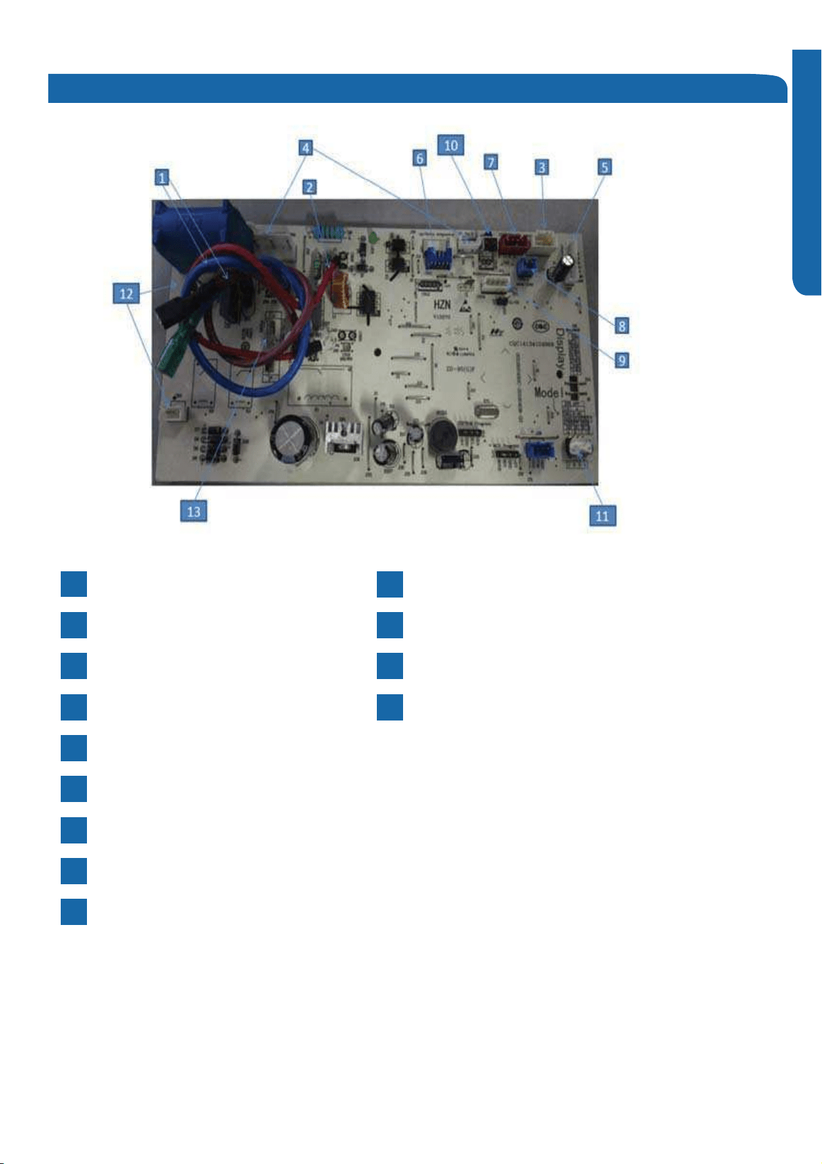
PCB
2CN23-Connector for communication between
indoor and outdoor unit
4CN8, CN9 (09k and 12k), or CN9 (18k and 24k) -
Fan motor connections
9CN51 (09k and 12k), or CN34 (18k and 24k) - WiFi connection
6
CN11 (09k and 12k), or CN5 (18k and 24k) -
Up/down stepper motor connections
11 SW2-1-Select remote code A or B
CN3 and CN1 (09k and 12k) - transformer connection
13
3,4- Select EEPROM code 22,25,33 or 35
CN21, CN52-Connector for power N and L
1
CN51-Connector for room card
8
CN7- Connector for display
5
2-Select enable or disable room card
12
CN6-Connector for thermistors
3
SW1- Connector for emergency ON/OFF switch
10
CN2-Connector for wired controller
7
FUSE1- Fuse 3.15A/250 VAC
CN11 and CN10 (18k and 24k) - Left/right stepper motor connections
INDOOR UNIT CONTROLS and COMPONENTS
PAGE 16
ENGLISH
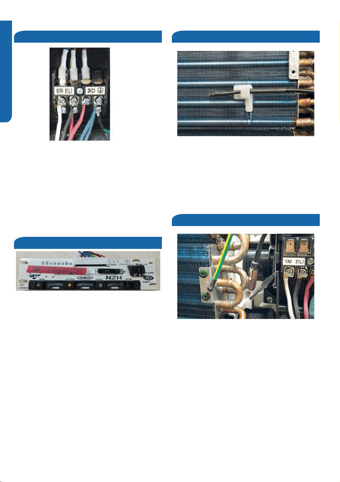
Terminal Block
Display
Ambient Temperature Sensor
Coil Temperature Sensor
The terminal block receives electrical power from the
outdoor unit.Terminals 1 and 2 are connected to terminals
1 and 2 of the outdoor unit. This wiring supplies power to the
indoor unit.
Terminal 3 is a communication wire. The indoor unit sends
indoor air temperature, coil temperature and temperature
set point information to the outdoor unit on this wire. If a
splice or break in this wire is present, the indoor unit will not
be able to communicate with the outdoor unit. The ERROR
CODE will be E7.
The Ambient Sensor is a negative coefficient thermistor
that will decrease in resistance with increases in room air
temperature. The sensor is located on a clip mounted
to the surface of the indoor coil.
The sensor connects to the control board at Plug CN-6.
The indoor display is an infrared communication circuit that
receives operating commands from the remote control. This
display will indicate operating modes, error codes, indoor air
temperature, timer and power status. The Coil Sensor is a negative coefficient thermistor that
will decrease in resistance with increases in coil temperature.
The sensor is located in a socket soldered to the surface of
the indoor coil.
This sensor will monitor the temperature of the indoor coil
in both cooling and heating. Should abnormally cold or hot
coil temperature be detected by this sensor, the system
will take steps to correct the condition or report an error
code.
The sensor connects to the control board at Plug CN-6.
INDOOR UNIT CONTROLS and COMPONENTS PAGE 17
ENGLISH
Stepper Motor and Louver
Fan Motor
Emergency Button
The Stepper Motor moves the louver up and down
(09k and 12k), and also right to left (18k and 24k).
The motors can be set to move automatically or to several
fixed positions.
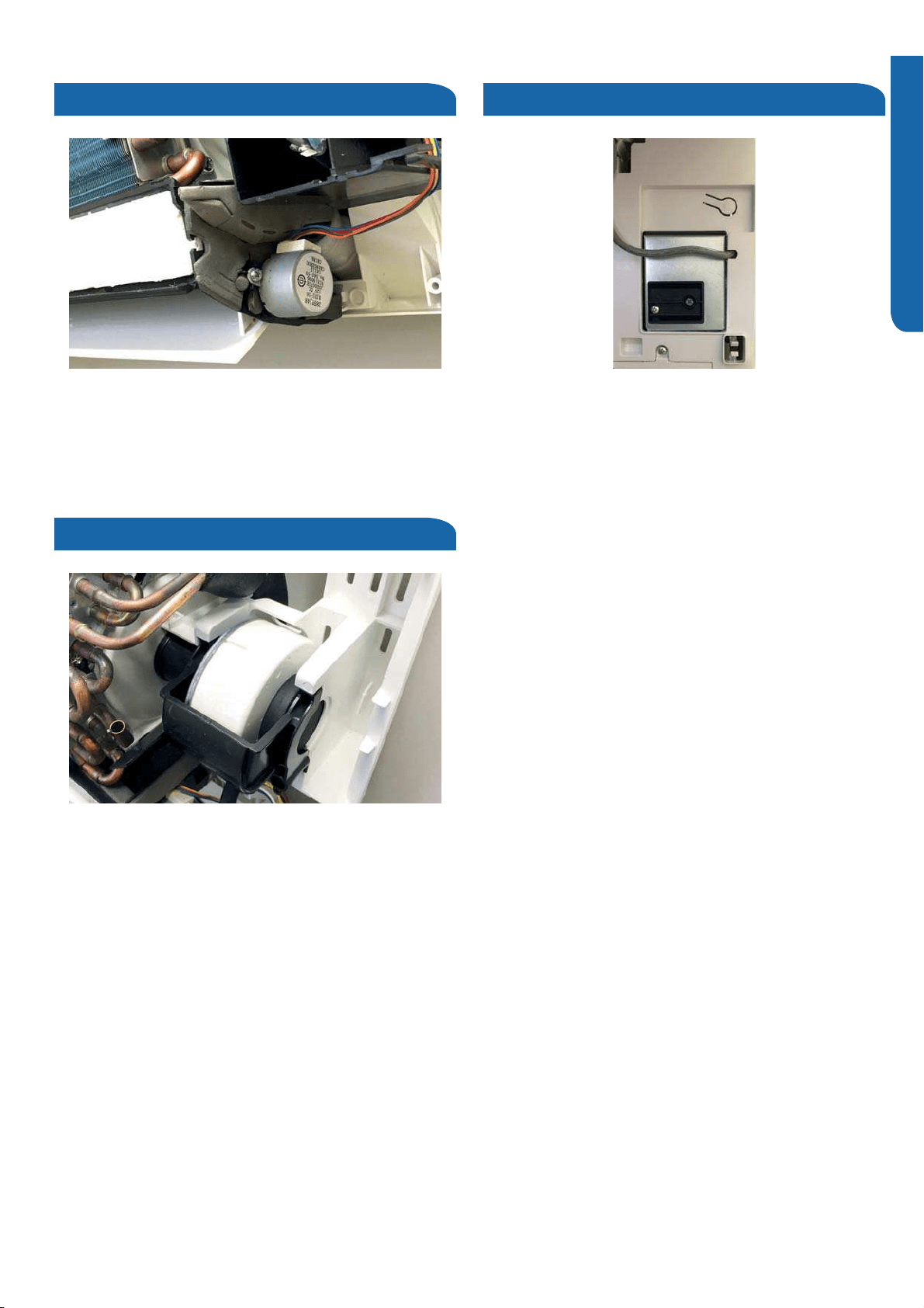
The Fan Motor is a variable speed DC motor. The
motor will vary speed with the speed of the compressor.
It will operate automatically or at a preselected fixed speed.
When in AUTO fan mode, the speed of the fan is calculated
using the difference between the set and room temperatures.
The fan motor is connected to the PCB at CN8 and CN9
(09k and 12k), or CN9 (18k and 24k).
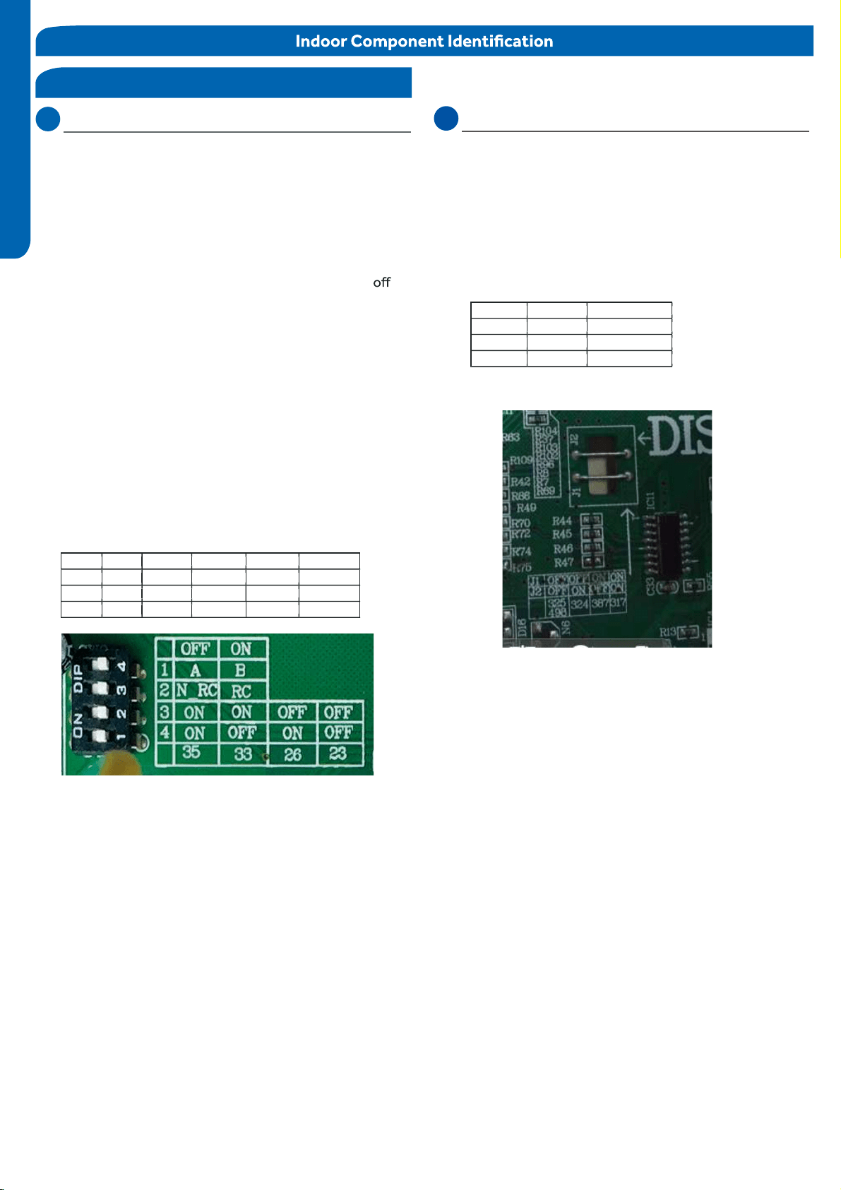
If the remote control is non-functional, the Emergency
Button can be accessed by swinging open the front of the wall
unit. The button is located on the right side.
The system will maintain approximately 75 degrees until
the remote is reactivated, or the power is turned off and back
on.
REMOTE CONTROL FUNCTIONS
PAGE 18
ENGLISH
ENGLISH
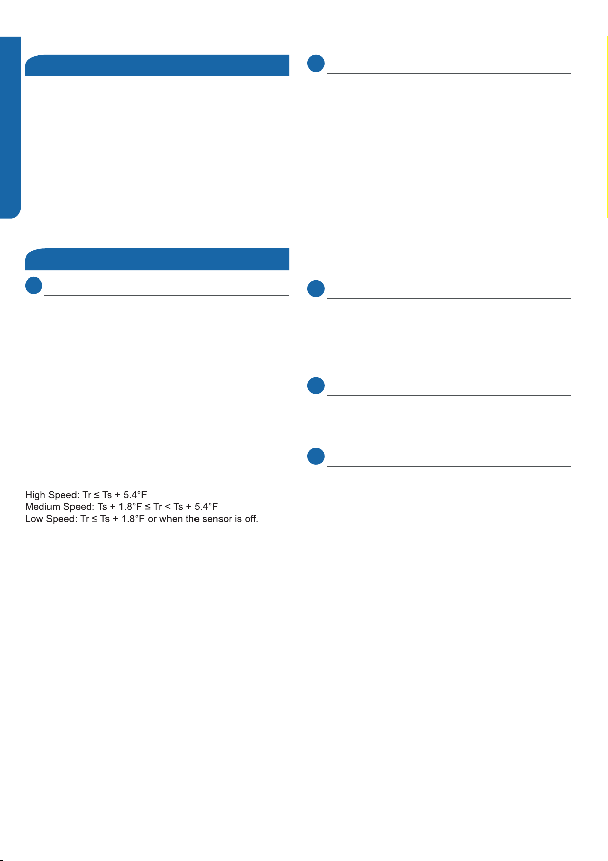
DIP
Switch
Settings
The
PCB
for
the
indoor
unit
of
the
Tempo
series
of
single
z
one
mini-splits
has
a
set
of
DIP
switches
that
must
be
set
when
replacing
the
PCB.
The
replacement
PCB
is
shipped
with
all
switches
set
to
the
OFF
position.
S
witch
settings:
SW2-1
Selects
remote
code
A
or
B.
Normally
set
to
the
position
for
code
A
operation.
If
two
indoor
units
are
used
in
the
same
area
and
the
user
wishes
to
control
them
separately,
switch
SW2-1of
the
sec
ond
unit
is
set
to
the
ON
position
for
code
B
operation.
T
he
wireless
remote
for
the
second
unit
is
also
set
to
code
B.
SW2-2
Selects
room
card
able
or
disable.
Normally
set
to
the
OFF
position.
Set
to
the
ON
position
when
used
in
conjunction
with
a
room
card
interface
utilized
in ho
tel rooms.
SW-3
&
SW-4
Selects
eeprom
code
22,
25,
33
and
35.
Set
to
identify
the
tonnage
of
the
unit.
Settings:
9K (22) SW
(23)
-3 ON SW-4 ON
12K (25) SW-3 ON SW-4 OFF
(26)
18K (33) SW-3 ON
(33)
SW
-4 OFF
24
K
(35) SW-3 ON
(35)
SW
-4 ON
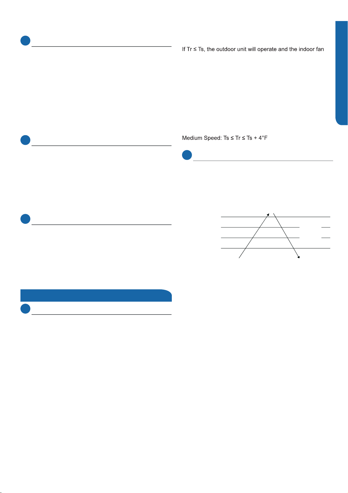
DIP Switch
Display Switch Settings
The PCB for the indoor unit of the Tempo series of
zone mini-splits has a set of Display switches that must be set
when replacing the PCB.
Settings:
)
09K
12K
18K
24K
(387)
(387)
(387)
(387)
J1: ON, J2:ON
J1: ON, J2:ON
J1: ON, J2:OFF
J1: ON, J2:OFF
Switch settings:
If two indoor units use different Display, or different PCB,
the PCB should switch J1 and J2. J1 set ON, meaning J1 should
be connected, J2 set OFF, meaning J2 should be cut.

SEQUENCE of OPERATION PAGE 19
ENGLISH
Sequence of Operation
Table of Contents
System Power .................................................................................................................................................................. 20
Cool Mode ........................................................................................................................................................................ 20
Overview ........................................................................................................................................................................................ 20
Indoor Unit ..................................................................................................................................................................................... 20
Temperature Sensors .................................................................................................................................................................... 20
Communication ............................................................................................................................................................................. 20
Outdoor Unit .................................................................................................................................................................................. 20
Temperature Sensors .................................................................................................................................................................... 21
Call to Terminate Cooling ............................................................................................................................................................. 21
Freeze Protection.............. ........................................................................................................................................................... 21
Heat Mode ........................................................................................................................................................................ 21
Overview ........................................................................................................................................................................................ 21
12................................................................................................................................................................ noitarepO foorP riA dloC
Defrost ........................................................................................................................................................................................... 22
noitasnepmoC erutarepmeT gnitaeH citamotuA
......................................................................................................................
. 22
Indoor Unit ..................................................................................................................................................................................... 22
Temperature Sensors .................................................................................................................................................................... 22
Communication ............................................................................................................................................................................. 22
Outdoor Unit .................................................................................................................................................................................. 22
Temperature Sensors .................................................................................................................................................................... 22
....................................................................................................
......................................................... 22
Dry Mode ......................................................................................................................................................................... 22
Overview ........................................................................................................................................................................................ 22
Indoor Unit ..................................................................................................................................................................................... 23
Temperature Sensors .................................................................................................................................................................... 23
Communication ............................................................................................................................................................................. 23
Outdoor Unit
.................................................................................................................................................................................. 23
Temperature Sensors .................................................................................................................................................................... 23
Defrost ............................................................................................................................................................................ 23
Protection Functions ........................................................................................................................................................ 23
High Temperature Protection ..................................................................................................................................................... 23
.............................................................................................................. 23
Compressor Overcurrent Protection........................................................................................................................... 24
........................................................................................................................................24
Overheating protection for indoor unit........
Indoor Coil Freeze Protection
Call to Terminate Heating
SEQUENCE of OPERATION
PAGE 20
ENGLISH
System Power
Cool Mode
Overview
Indoor Unit
Temperature Sensors
Communication
Outdoor Unit
The 240 VAC power for the system connects to terminals
1(N), 2(L), and ground of the outdoor unit terminal block. This
terminal block also connects power to the indoor unit.
The voltage readings between terminals 1(N) and ground, and
terminals 2(L) and ground should be 120 VAC. The voltage
reading between terminals 1(N) and 2(L) should be 230 VAC.
One additional connection on the terminal block (3) is for the
communication wire between the indoor and outdoor units.
NOTE: Mis-wiring of these connections may cause improper
operation or damage to system components.
The temperature control range in cooling mode is 60°F - 86°F.
The temperature set at the remote control and room ambient
temperature sensor will determine if a call for cooling is
needed.If justified, the call is communicated from the indoor
unit to the outdoor unit. The indoor unit louver will open using
a stepper motor, and the indoor fan will operate at the speed
last set. The outdoor unit will determine the position of the
EEV and speed (frequency)
of the compressor. There can be a delay of up to 3 minutes
before the outdoor unit fan and compressor start.
The speed of the indoor fan can be controlled manually by
the user or automatically by the system. The speed can be
changed between LOW, MEDIUM, and HIGH. The
predetermined conditions for automatic control are as follows:
(Tr= room temperature Ts= set temperature)
There will be a 2 second delay when manually controlling the
speed.
The outdoor unit temperature sensors; outdoor ambient,
defrost, suction line, and compressor discharge, used in
conjunction with the indoor temperature sensors (ambient
and coil), provide information to the outdoor control board
to monitor the system and regulate the frequency of the
compressor, EEV positioning, and outdoor fan speed to
achieve the desired room temperature.
When cooling has been satisfied, the compressor
will turn off, followed by the outdoor fan. The indoor unit
fan will continue to run.
If the system detects a malfunction, it may shut down, or
show an error code on the indoor unit display board and/or
outdoor PCB.
To enter the cool mode, point the infrared remote control at
the indoor unit , press the power button, then press the COOL
button if not already set.
The indoor unit main board will activate the display The PCB
will illuminate the display, indicating the temperature and
current unit status.
The indoor unit main board will signal the louver stepper motor
to open the louver to either a stationary position, or one
of several oscillating modes.
As the louver opens, the main board will power up the fan motor,
operating the fan at the speed last set.The motor has a feedback
circuit which provides the main board with information for
controlling the speed of the fan motor.
Ambient (room) and coil temperature sensors are used to
control the system in the cooling mode.The resistance values
of the sensors will vary with temperature.values can be found
using a temperature / resistance chart specific to the sensor
being checked.
The indoor and outdoor unit main boards communicate via a
digital signal on the wire connected to Terminal 3 of each unit.
A splice or break in this wire will cause a communication error.
Upon a request for cooling, the PCB applies power to the
outdoor fan motor and compressor. Depending on system
cycling, there may be up to a 3 minute wait before the
compressor and outdoor fan start.
WARNING: Do not measure compressor voltages as damage to
the meter may result.
If the room temperature is less than the set temperature,
yet higher than 2°F below the set temperature, the
system will adjust the running frequency of the compressor
automatically.
The PCB also controls the position of the
EEV (Electronic Expansion Valve)
to regulate the flow of refrigerant to the evaporator
coil.
SEQUENCE of OPERATION PAGE 21
ENGLISH
Temperature Sensors
Call to Terminate Cooling
Freeze Protection
Heat Mode
Overview
Cold Air Proof Operation
Four temperature sensors provide temperature information
The ambient sensor provides the temperature of the air
drawn into the condenser coil of the outdoor unit.
The defrost sensor provides the temperature sensed at the
output of the condenser coil.
The suction line sensor provides the temperature sensed at
the incoming suction line pipe.
The compressor discharge sensor provides the temperature
sensed at the discharge pipe of the compressor.
The system will terminate cooling when the room
temperature is not more than two degrees below the set
temperature. The compressor stops, while the outdoor
fan continues running for another 60 seconds.
The indoor fan motor and louver will continue operating after
cooling has been terminated.
To stop cool mode, press the power button to turn the system
off, or change to another mode.
The temperature control range in heating mode is 60°F - 86°F.
The temperature set at the remote control and the room
ambient temperature sensor will determine if a call for
heat is needed. If justified, a temperature compensation
adjustment is automatically added to the
operating parameter and the call is communicated from the
indoor unit to the outdoor unit.
The louver will open using a stepper motor. The indoor
fan will not operate until the coil warms sufficiently
to keep cold air from circulating in the room.
The outdoor unit will shift the 4-way valve to the heating
and determine the position of the EEV and speed
(frequency) of the compressor. There can be adelay of up to
3 minutes before the outdoor fan and compressor start.
(Tr = room temperature Ts = set temperature)
operates in cold air proof operation
If Tr > Ts+, the outdoor unit turns off and the indoor fan
will circulate any residual heat remaining in the coil.
If Tr < Ts+, the outdoor unit will restart and the indoor fan
operates in cold air proof operation.
The speed of the indoor fan can be controlled manually by
the user or automatically by the system. The speed can be
changed between HIGH, MEDIUM, and LOW. The
predetermined conditions for automatic control are as
follows:
High Speed: Tr < Ts
Low Speed: Tr > Ts + 4°F
At initial start of heat mode, indoor blower will not be turned
on until the coil has reached a minimum temperature. This
delay period can be up to 3 minutes, depending on the
difference between the room and the set temperature.
This period usually takes 30 seconds to 3
minutes depending on the outdoor ambient temperature.
The outdoor unit sensors; ambient,defrost, suction line, and
compressor discharge, used in conjunction with the indoor
sensors,
to the PCB for control of the system.
To prevent the indoor coil from becoming too cold during
low load or high humidity days, and when the compressor
has been running for 10 seconds with the coil temperature
at or below 32 degrees, the compressor will stop
automatically. The indoor fan will continue to run, using
room air to warm the coil. When the coil temperature
has reached 45 degrees for 3 minutes or more, the
compressor will start to resume the cooling operation.
ambient and coil, provide information to the outdoor control
board to monitor the coil and regulate the frequency of
the compressor, EEV positioning, and outdoor fan speed to
achieve the desired room temperature.
When heating has been satisfied, the outdoor unit compressor
will turn off first and followed by the outdoor fan. The
4-way valve will de-energize 2 minutes after the compressor
stops.
The indoor unit fan will continue to run at a very low speed
until any heat remaining in the coil is circulated into the room.
If the system detects a malfunction, it may shut down or
show an error code on the indoor unit display board and/or
outdoor unit main board LED.
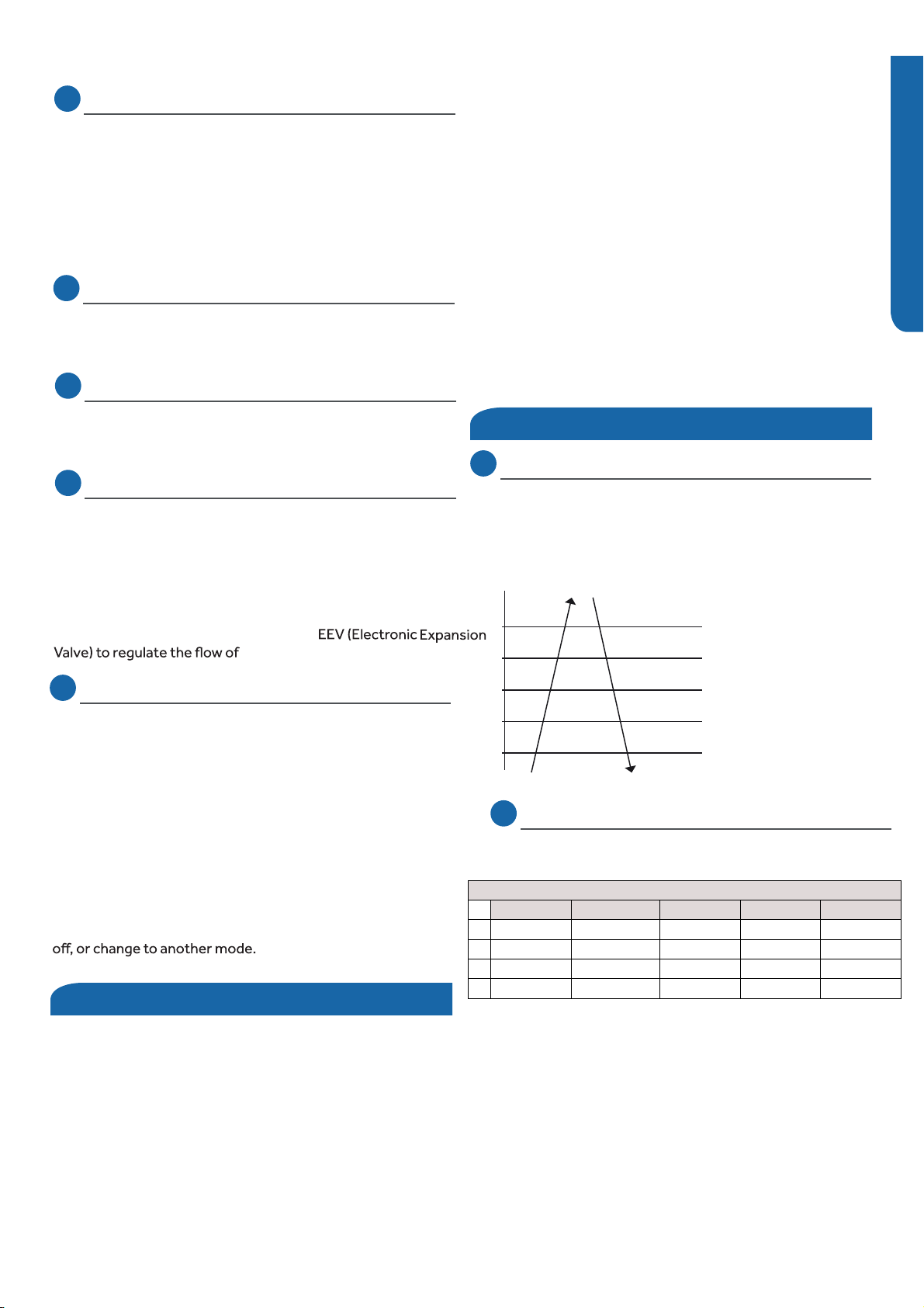
Heat start temp 1 Heat start temp 2 Heat start temp 3 Heat start temp 4 Set speed Low speedLight speed Fan/off Fan/off Keep the highspeed. The fandoesn’t stop
SEQUENCE of OPERATION
PAGE 22
ENGLISH
Defrost
Indoor Unit
Temperature Sensors
Communication
Outdoor Unit
Temperature Sensors
When the system initiates a call for defrost, the indoor fan
motor stops. The indoor unit display will not change.
The system will cycle through the defrost operation.Any
indoor unit malfunctions will be ignored until the compressor
restarts and has been operating for 30 seconds.At the
conclusion of the defrost cycle, the indoor fan will enter the
cold air proof operationand heating resumes.
To enter the heat mode, point the infrared remote controller
at the unit and press the power button, then press the HEAT
mode button if not already set.
The louver stepper motor to open the louver to a stationary
position.
The indoor and outdoor units main boards communicate via
the wire connected to terminal 3 of each unit.A splice or break
in this wire will cause a communication error.
Upon a request for heat, the PCB applies power to the 4-way
valve,outdoor fan motor, and compressor.Depending on
system cycling, there may be up to a 3 minute wait period
before the compressor and outdoor fan start.
NOTE: Do not measure compressor voltages , damage to the
meter may result.
If the room temperature is above the set temperature,yet lower
than 2°F above the set temperature, the system will adjust the
running frequency of the compressor automatically.
The PCB also controls the position of the
EEV (Electronic Expansion Valve)
to regulate the flow of refrigerant to the indoor unit evaporator
coil.
Four sensors provide temperature information to the main board
for control of the system during heat mode.
The ambient sensor provides the temperature of the air drawn
into the evaporator coil.
The defrost temperature sensor provides the temperature
sensed at the output of the evaporator coil.
The suction line sensor provides the temperature
sensed at the incoming suction line pipe.
The PCB will illuminate the display, indicating the temperature
and current status.
The louver opens to the lowest downward position, then the
fan motor starts after the coil has warmed to a sufficient
temperature (cold air proof operation). The PCB sends the
motor information to monitor the speed if in the AUTO mode,
or returns the motor to the fixed speed set previously.
The room (ambient) and coil sensors are used to maintain
the system at the temperature desired. The resistance values
of the sensors can be verified using the temperature-to-
resistance charts found in this manual.
Call to Terminate Heating
The compressor discharge sensor provides the temperature
sensed at the discharge pipe of the compressor.
The system will call to terminate heating when the temperature
is equal to or higher than 2°F above the set temperature.
The PCB
will de-energize
the compressor. The outdoor fan will run for 60 seconds
before stopping, and the 4-way valve will de-energize 2 minutes
after the compressor stops.
To stop heat mode, press the power button to turn the system
Dry Mode
Overview
(Tr = room temperature Ts = set temperature)
When Tr > Ts + 4°F, the compressor will turn on and the indoor
fan will operate at the set speed.
high dry frequency for 10 minutes, then at the HIGH DRY and
LOW DRY mode for 6 minutes. The indoor fan will operate at
LOW speed. When Tr < Ts, the outdoor unit will stop, and the
indoor fan will stop for 3 minutes, then operate at the LOW
speed option.
Automatic fan speed:
When Tr >= Ts + 9°F, HIGH speed
When Tr < Ts + 3.6°F, Light speed
controller.
If the outdoor fan is stopped, the indoor fan will pause for 3
minutes.If the outdoor fan is stopped for more than3 minutes,
and the compressor is still operating, the sindoor fan will change
to low speed mode.
Dry mode helps remove excess moisture from the room
during periods of high humidity.
SEQUENCE of OPERATION PAGE 23
ENGLISH
Indoor Unit
Temperature Sensors
Communication
Outdoor Unit
The PCB will signal the louver stepper motor to open the to
either a stationary position or one of several oscillating
modes.
As the louver opens, the PCB will power up the fan motor,
The PCB controls the fan speed if set to the Auto position,
or signals the motor to operate at a fixed speed previously
set.the speed of the fan motor.
The indoor and outdoor unit units communicate via the wire
connected to terminal 3 of each unit.A splice or break in this
wire will cause a communication error.
Upon a request for dry mode, the PCB applies power to the
fan motor outdoor and compressor.Depending on system
cycling, there may be up to a 3 minute wait period before the
compressor and outdoor fan start.
WARNING: Do not measure compressor voltages as damage
to the meter may result.
The PCB also controls the position of the
refrigerant to the evaporator coil.
Use same language here as used in the heating section,
inserting dry mode in place of heat or heating.
Temperature Sensors
Four sensors provide temperature information to the PCB for
control of the system during dry mode.
The ambient sensor provides the temperature of the air drawn
into the condenser coil of the outdoor unit.
The defrost sensor provides the temperature sensed at the
output of the condenser coil.
The suction line sensor provides the temperature sensed at the
incoming suction line pipe.
The discharge sensor provides the temperature sensed at the
discharge pipe of the compressor.
To stop dry mode, press the power button to turn the system
Defrost
Protection Functions
1. High Temperature
The PCB monitors the temperature difference between the
ambient and defrost sensors as the coil becomes colder.
A defrost cycle will initiate when this difference grows beyond
an acceptable level. To enter a defrost cycle, the compressor
must have accumulated 10 minutes of run time and 45 minutes
of run time since the last defrost.
The discharge (exhaust) sensor monitors the temperature
of the refrigerant leaving the compressor. Compressor
speed will either increase, decrease, or the compressor may
stop in response to temperatures reported by the discharge
sensor. Refer to the table below.
When a call for defrost initiates, the compressor slowly ramps
down, then runs for 30 seconds at a very low speed.
1 minute from the call for defrost, the 4WV switches to cooling,
all fans stop, and the EEV changes to a mid-range. Once these
functions are completed, the compressor ramps up to a high
speed.
When the outdoor coil reaches more than 45 degrees for 60
seconds, or more than 54 degrees for 30 seconds, the defrost
cycle will terminate. The compressor then returns to a very
low speed for 1 minute while all components return to the
heating mode.
The defrost cycle is terminated automatically after 10 minutes
if the coil does not reach the specified temperatures.
Abnormal stop
Decreasing the frequency rapidly (1HZ/1second)
230°F
212°F
209°F
199°F
194°F
Decreasing the frequency slowly (1HZ/10 seconds)
The frequency doesn’t change
Increasing the frequency (1HZ/10 seconds)
Increasing the frequency (1HZ/1second)
2. Overheating protection for indoor unit
coil sensor monitors temperature at the coil surface
according to the table below.
Overheating protection for indoor unit
Increasing slowly
Decreasing slowly
Decreasing rapidly
Compressor stop
Prohibiting increasing
48℃/118℉51℃/124℉56℃/133℉59℃/138℉63℃/145℉63℃/145℉63℃/145℉63℃/145℉59℃/138℉60℃/140℉60℃/140℉56℃/133℉56℃/133℉56℃/133℉51℃/124℉53℃/127℉53℃/127℉48℃/118℉48℃/118℉48℃/118℉09K
12K
18K
24K
SEQUENCE of OPERATION
PAGE 24
ENGLISH
59°F // ice_temp_3+5
46°F // ice_temp_3+2
43°F
Decreasing slowly
Decreasing rapidly ice_temp_1
Stop
Keeping the frequency
Increasing slowly
32°F
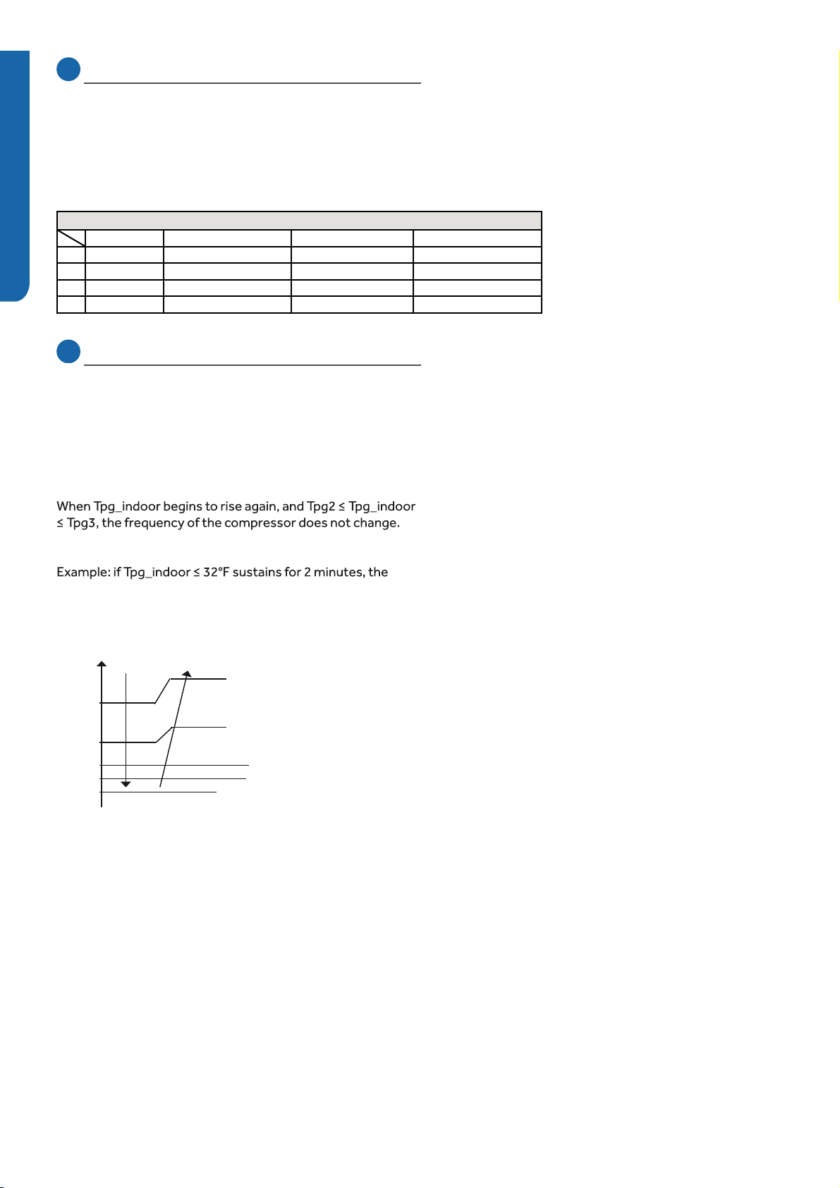
Tpg1=37°F
Tpg2=41°F
Tpg3=43°F
Tpg4=
48°F
3. Compressor Overcurrent Protection
4. Indoor Coil Freeze Protection
If the current draw of the compressor at start-up is greater
than the values in the chart below for approximately 3 seconds,
the compressor will stop and a code will be indicated at the
outdoor unit. After 3 minutes the compressor will restart.
If the overcurrent condition occurs 3 times in 20 minutes,
the system will lock out.It will be necessary to remove power
to the system to reset the lock outcondition.
Tpg_indoor: indoor unit pipe sensor temperature
When Tpg_indoor < Tpg1, the frequency of the compressor
decreases at the rate of 1HZ / 1 second.
When Tpg_indoor < Tpg2, the frequency of the compressor
decreases at the rate of 10HZ / 10 seconds.
When Tpg3 < Tpg_indoor <Tpg4, the frequency of the compressor
increases at the rate of 1HZ / 10 seconds.
outdoor unit will stop and indicate an underload malfunction
code at the outdoor unit. The compressor stops for a minimum
of 3 minutes. When Tpg_indoor >Tpg4, the compressor
will restart.
The coil sensor protects the coil from becoming too cold during
low cooling load days or periods of high humidity.
Current overload protection
No charge
12A09K
12K
18K
24K
13A
14A
14A 15A
17A
15A
14.5A 15.5A
20A
19A
13.5A
18A
13A
13A
17A
Decrease 1Hz/10s Decrease 1Hz/s Over Current Point
ENGLISH
System
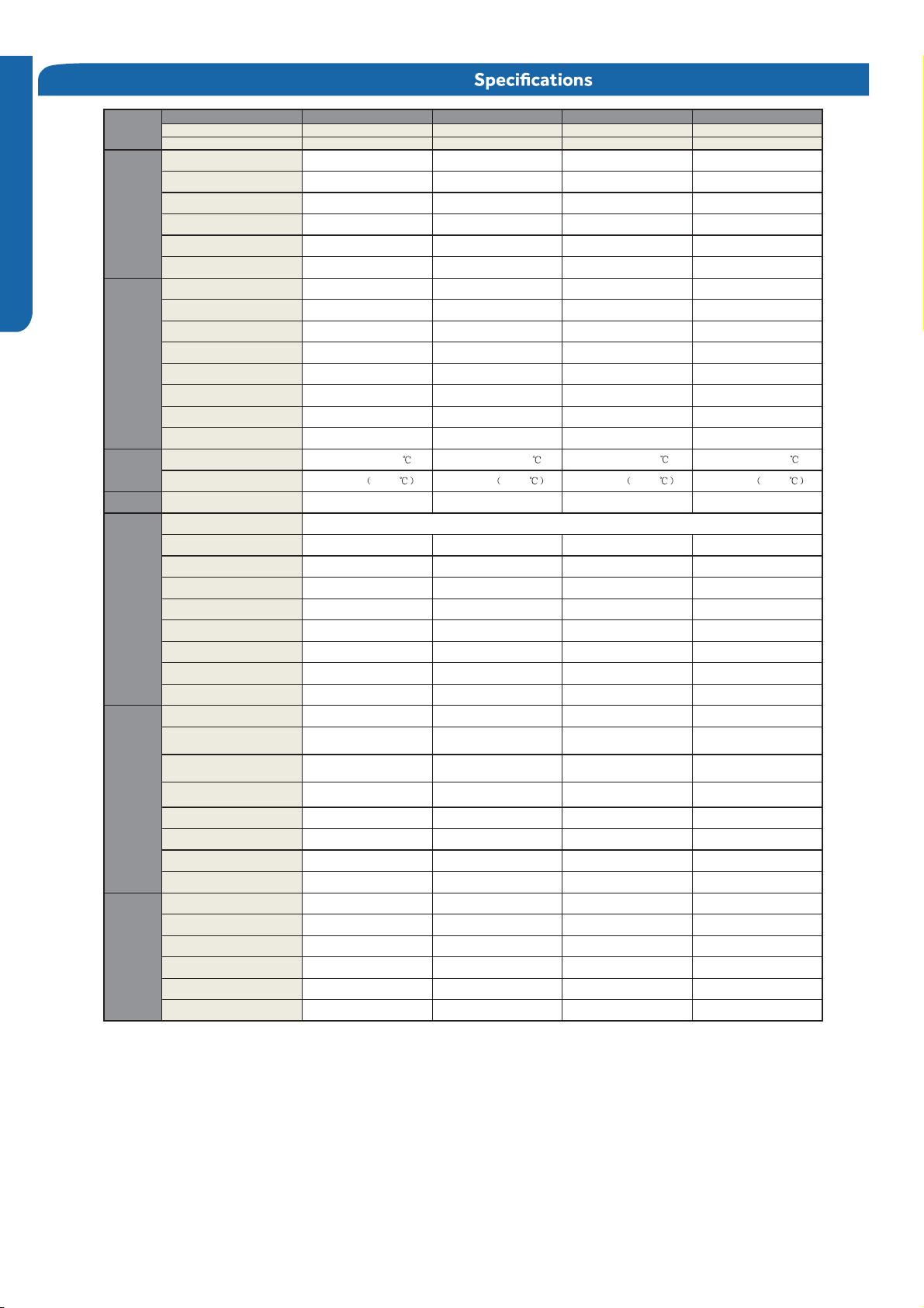
ET42ET81ET21ET90metsyS
Outdoor 1U09TE1VHA 1U12TE1VHA 1U18TE2VHA 1U24TE2VHA
Indoor AW09TE1VHA AW12TE1VH
A
AW18TE2VHA AW24TE2VHA
Rated Capacity Btu/hr 000,42000,81000,21000,9
Capacity Range Btu/hr 3,800~12,000 4,100~12,500 5,000~19,000 6,500~26,000
Rated Power Input W051,2056,1002,1018
61616161REES
0.010.010.110.11REE
Moisture Removal Pt./h 09.502.404.305.2
R
ated Heating Capacity 47°F
B
tu/h
r
000,62000,91000,21000,01
Heating Capacity Range Btu/hr 4,100~12,000 4,500~16,000 5,400~22,000 6,800~28,000
Rated Power Input W004,2007,1000,1058
0.90.90.90.9FPSH
R
ated Heating Capacity 17°F
B
tu/h
r
006,61002,11008,7006,5
M
ax. Heating Capacity 17°F
B
tu/h
r
003,91005,51000,01002,8
Heating Capacity 5°F Btu/hr 005,51004,21000,8006,6
Heating Capacity -4°F Btu/hr 009,21005,9002,6001,5
Cooling °F(°C) 14°F~115°F(-10~46 ) 14°F~115°F(-10~46 ) 0°F~115°F(-18~46 ) 0°F~115°F(-18~46 )
Heating °F(°C) -4°F~75°F -20-24 -4°F~75°F -20-24 -4°F~75°F -20-24 -4°F~75°F -20-24
Power Suppl
y
Voltage, Cycle, Phase V/Hz/- 115/60/1 115/60/1 208-230/60/1 208-230/60/1
Compressor Type
Maximum Fuse Size A52020202
Minimum Circuit Amp A91718181
Outdoor Fan Speed RPM 008008058058
DC Inverter Driven Rotary
Model Name
Cooling
Operating
Range
Heating
Outdoor Noise Level dB 35650574
Dimension: Height in (mm) 21 1/4(540) 21 1/4(540) 27 7/16 (697) 30 (762)
Dimension: Width in (mm) 30 11/16(780) 30 11/16(780) 35 (890) 36 3/16 (920)
Dimension: Depth in (mm) 9 5/8(245) 9 5/8(245) 13 7/8 (353) 15 1/8 (385)
Weight (Ship/Net)- lbs (kg) 66.2/58.4(30/26.5) 71.7/63.9(32.5/29) 105.8/97.0(48.0/44.0) 121.3/112.5(55.0/51.0)
Fan Speed Stages 5 + Auto 5 + Auto 5 + Auto 5 + Auto
Airflow
(Turbo/High/Med/Low/Quiet) CFM 305/295/280/265/240 310/300/287/275/245 545/530/505/475/460 665/650/610/570/555
Motor Speed
(Turbo/High/Med/Low/Quiet) RPM 1150/1050/950/850/750 1200/1100/1000/900/800 1150/1100/1000/900/850 1250/1200/1050/900/850
Indoor Sound Level dB
(Turbo/High/Med/Low/Quiet) 43-7433-5432-9332-93
Dimension: Height in (mm) 11 7/16(290) 11 7/16(290) 12 1/2(318) 13 3/16(335)
Dimension: Width in (mm) 34(864) 34(864) 39 11/16(1008) 44 5/16(1125)
Dimension: Depth in (mm) 7 7/8(200) 7 7/8(200) 8 7/8(225) 9 7/16(240)
Weight (Ship/Net)- lbs (kg) 24.7/19.9(11.2/9.0) 24.7/19.9(11.2/9.0) 33.1/26.5(15.0/12.0) 38.6/30.9(17.5/14.0)
eralFeralFeralFeralFsnoitcennoC
Liquid O.D. in 4/14/14/14/1
Suction O.D. in 2/12/18/38/3
Factory Charge Oz 0.766.043.535.62
Maximum Line Length Ft / m 52/3852/3802/6602/66
Maximum Height Ft / m 51/0551/0501/3301/33
Refrigerat
Lines
Outdoor Unit
Indoor Unit
INSTALLATION PAGE 25

INSTALLATION
PAGE 42
ENGLISH
[This page intentionall
y
left blank.]
>7KLVSDJHLQWHQWLRQDOO\OHIWEODQN@

Check This First Outdoor Unit .............................................................................................................................................................29
Check This First Indoor Unit ................................................................................................................................................................30
Wiring Diagram Reference...................................................................................................... .............................................................31
F1/LED1: 2 Flash
.....................................................................................................................................................................................32
F2/LED1: 24 Flash .................................................................................................................................................................................34
F3/LED1: 4 Flash ....................................................................................................................................................................................36
F4/LED1: 8 Flash ....................................................................................................................................................................................38
F6/LED1: 12 Flash
F7/LED1: 11 Flash
F21/LED1: 10 Flash
F25/LED1: 13 Flash
E1/LED1: No Flash
E2/LED1: No Flash .................................................................................................................................................................................40
F6/LED1: 12 Flash, F7/LED1: 11 Flash, F21/LED1: 10 Flash, F25/LED1: 13 Flash,
E1/LED1: No Flash, E2/LED1: No Flash.................................................................................................................................................41
F8/LED1: 9 Flash .....................................................................................................................................................................................42
F11/LED1: 18 Flash .................................................................................................................................................................................44
F12/LED1: 1 Flash ...................................................................................................................................................................................46
E5/LED1: 22 Flash....................................................................................................................................................................................47
E7/LED1: 15 Flash ...................................................................................................................................................................................49
Error Code (Indoor)
E14 ............................................................................................................................................................................................................52
Checking System Components...............................................................................................................................................................54
ERROR CODES and Troubleshooting
Error Code (Indoor/outdoor)
PAGE 27
Troubleshooting
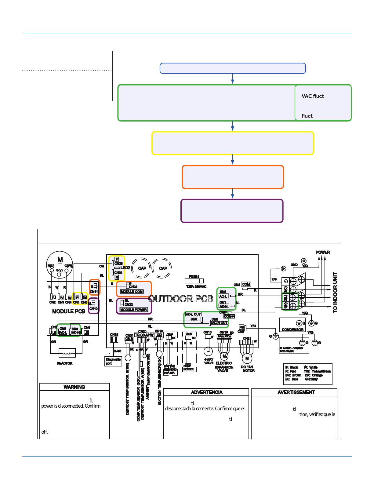
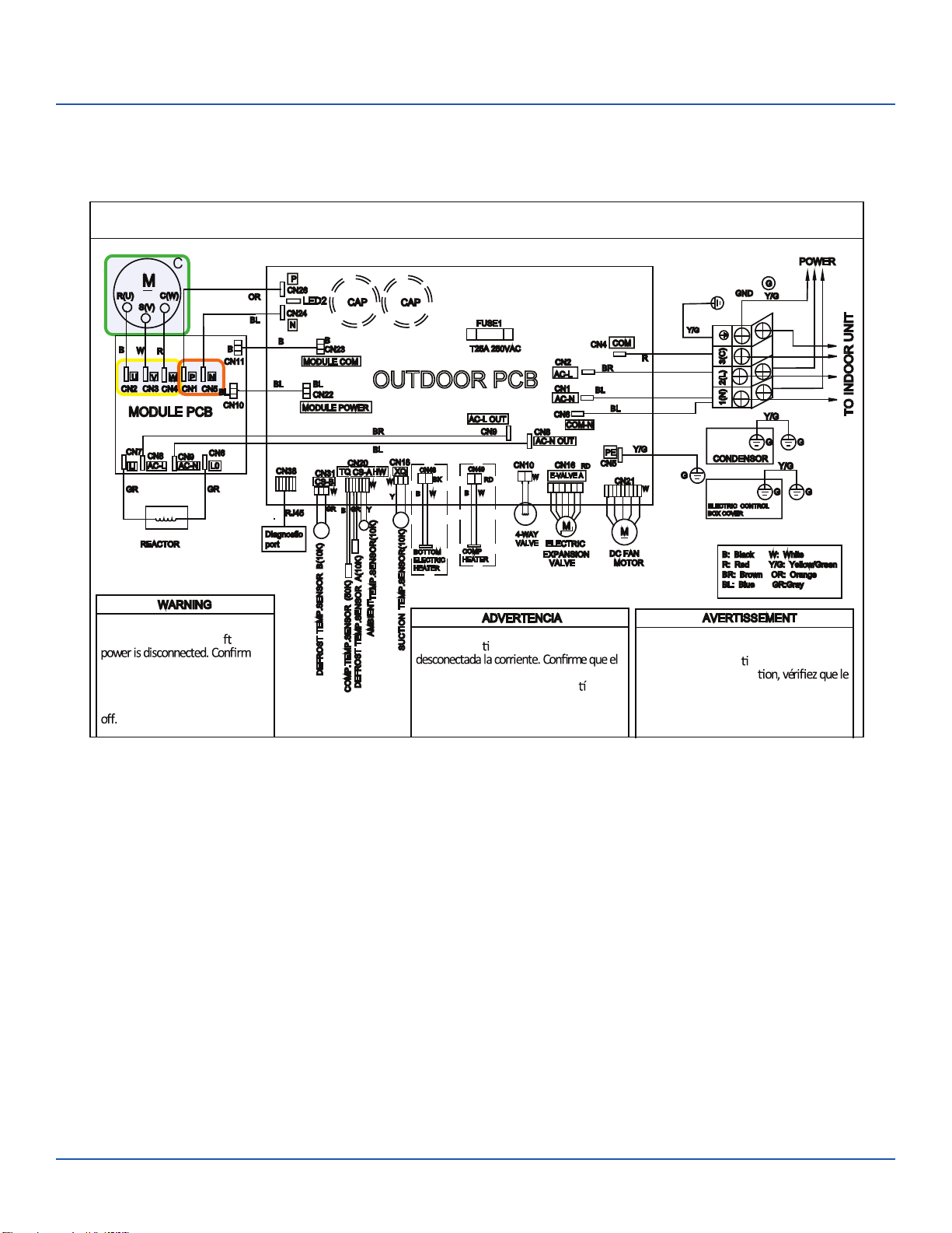
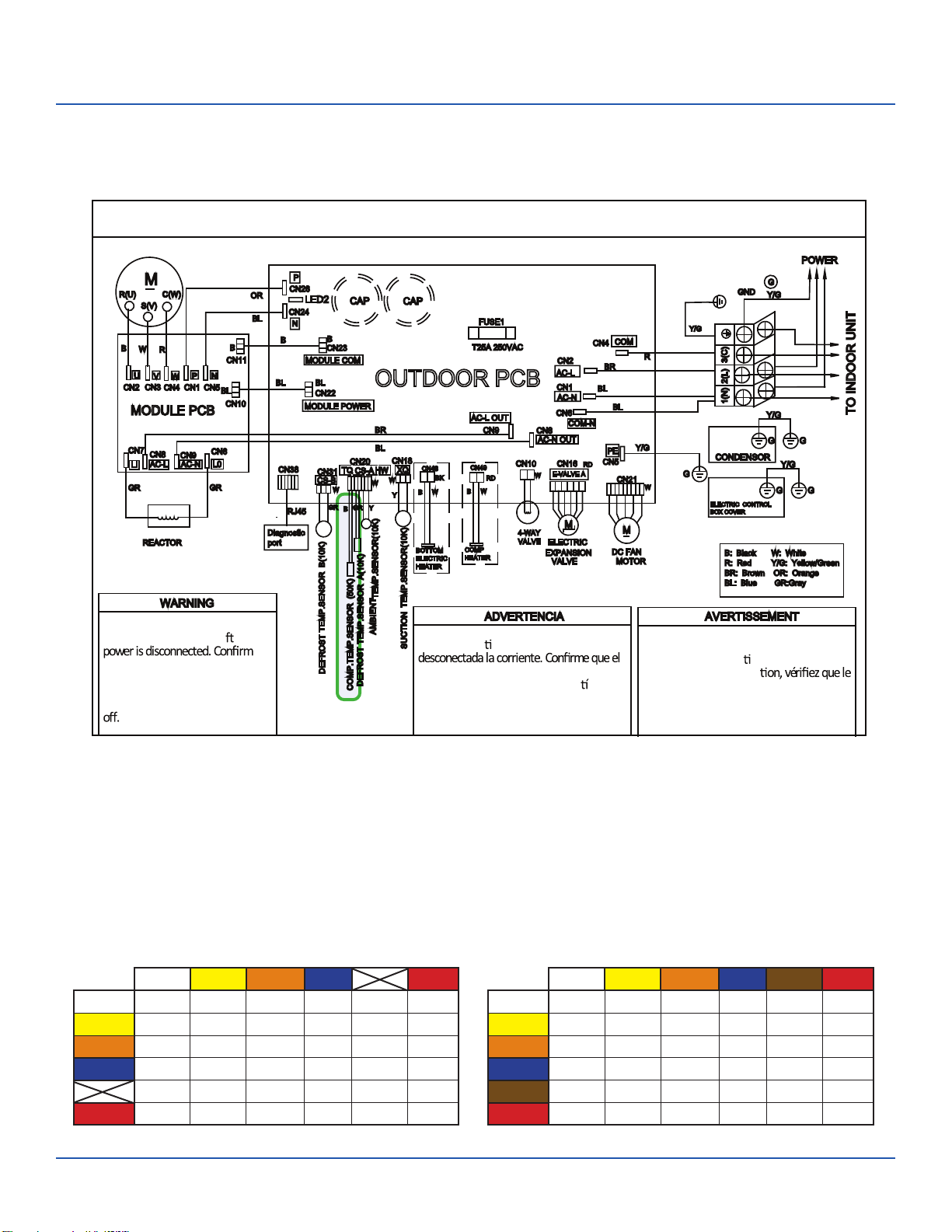
OUTDOOR UNIT WIRING DIAGRAM
COMPRESSOR
Electrical Shock Hazard
Capacitor retains charge a er
voltage at capacitor has dissipated
(<10V DC) with hand held voltmeter
before servicing. LED2 light
between CN24 and CN26 should be
Riesgo de Descarga Eléctrica
El capacitor re ene carga una vez
voltaje del capacitor se haya disipado (<10V
DC) apoyando la mano sobre el vol metro
antes de realizar el servicio técnico. La luz
LED2 que se encuentra entre CN24 y CN26
deberá estar apagada.
Risque de choc électrique
Le condensateur conserve sa charge après la
coupure de l’alimenta on électrique. Avant
de procéder à une répara
courant au condensateur s’est dissipé
(<10 VCC) à l’aide d’un voltmètre manuel. Le
voyant LED2 entre CN24 et CN26 doit être
éteint.
0011509127
Check This First
Outoor UnitModels:
ASH109CRAWA
ASH112CRAWA Line voltage available at:
1. TERMINAL STRIP - 1(N) & 2 (L)
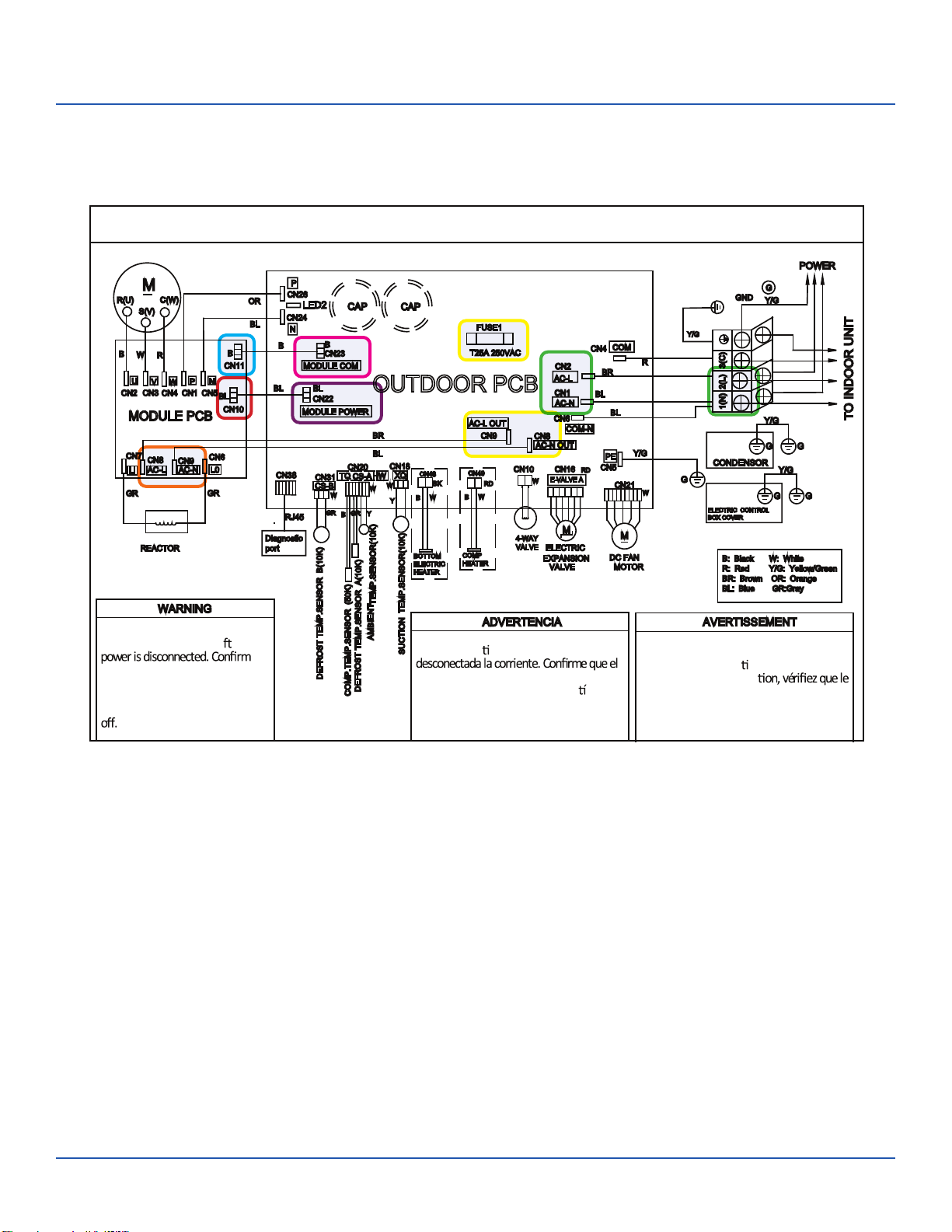
2. AC-L & AC-N at the PCB - CN2 & CN1
3. AC-L OUT & AC-N OUT at the PCB - CN8 & CN9
4. AC-L & AC-N at the IPM -CN8 & CN9 (9K) / CN1 & CN2 (12K/18K)
310+ VDC available at:
1. P & N at the IPM - CN1 & CN5 (9K) / CN8 & CN9 (12K/18K)
2. P & N at the PCB - CN24 & CN26
Module COM 5-G-15 VDC available at:
1. CN23 at the PCB
2. CN11 at the IPM
Module power 5-G-15 VDC available at:
1. CN22 AT THE PCB
2. CN10 AT THE IPM
• 1 (N) and 3 (C): 0-80
uating
• 2 (L) and 3 (C):
0-140 VAC
uating
Wiring Diagram Reference
Conditions Needed for Basic Operation
3-minutes of time delay from the call for heating or cooling
ERROR CODES and Troubleshooting
PAGE 28
ASH118CRDWA
ASH124CRDWA

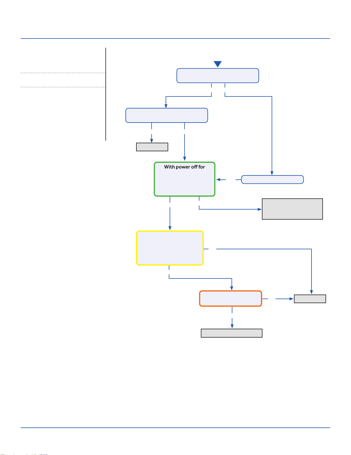
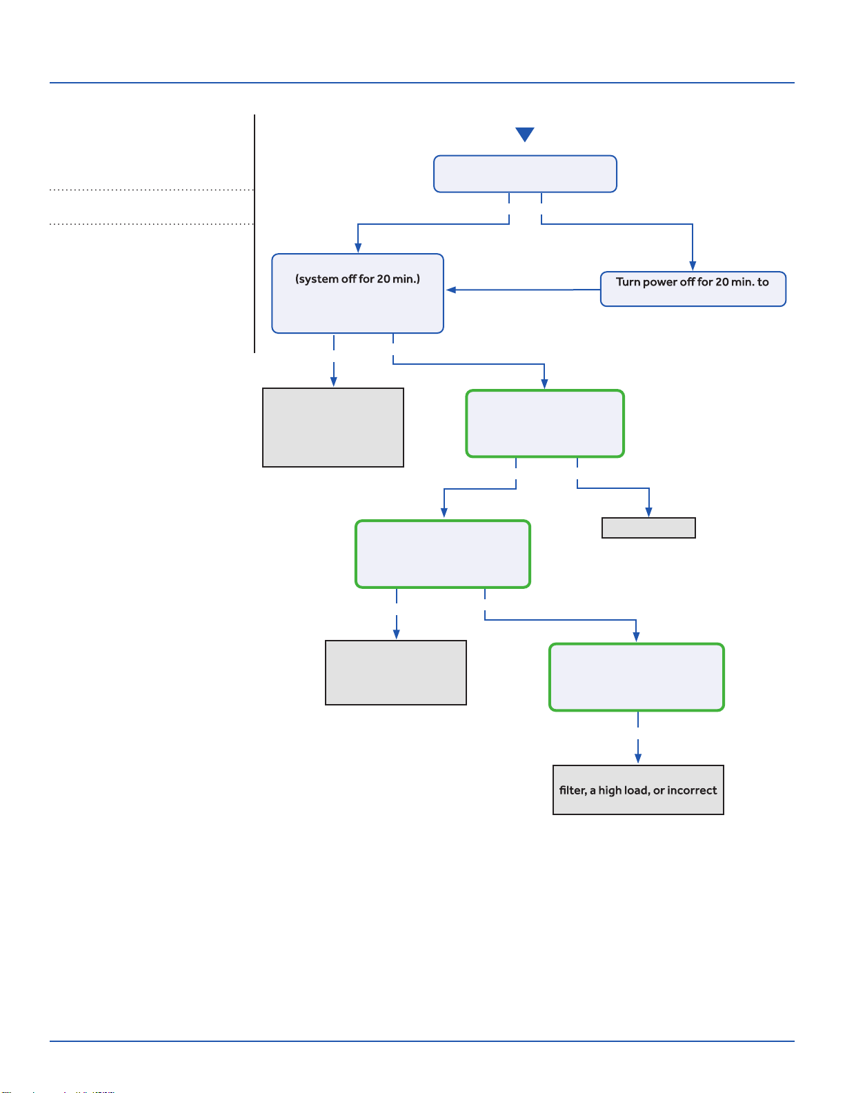
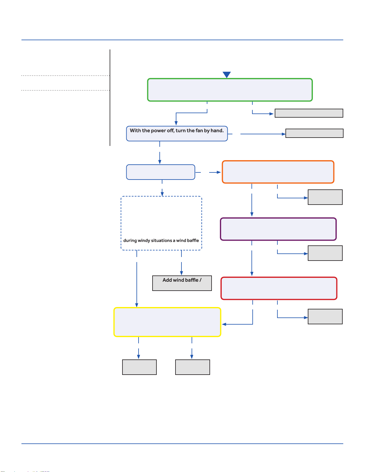
Troubleshooting
Start
See reverse side for
wiring diagram and
relevant color-coded
test positions.
Yes
Yes
Yes
Yes
No
No
No
Yes No
No
Determine source of lost
power from OD unit or phase
imbalance from building power
Determine source of lost
communication from OD unit
Replace PCB
Replace sensor
There is 230 VAC (+/- 10%) at terminal
strip connections 1(N) and 2(L), and
no more than a 2% deviation between
each leg and ground?
There is a pulsing 0 to 80
VAC between terminal strip
connections 1(N) and 3(C)?
There is 230 VAC at
terminals CN17 and CN21
on the PCB, and the LED
There is 5 VDC at CN6
across both sets of black
sensor wires?
The sensor resistance is
within 3% of the value listed
in the Service Manual sensor
resistance table?
Wiring and connections
are in good condition?
Check This First
Indoor UnitModels:
ERROR CODES and Troubleshooting PAGE 29
ASYW09CRAWA
ASYW12CRAWA
ASYW18CRDWA
ASYW24CRDWA
Troubleshooting
Check This First - Indoor Unit
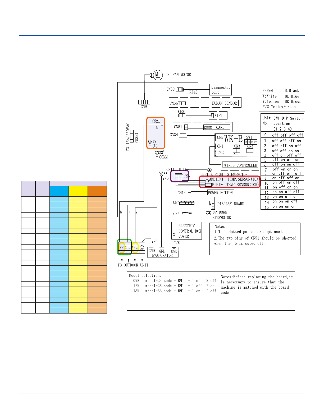
Wiring Diagram Reference
Sensor Resistance Table
°F °C
Normal (KΩ
10K
SENSORS
23K
SENSORS
50K
SENSORS
-0.4 -18 75.44 235.90 5494.21
5.0 -15 64.30 196.61 4558.19
10.4 -12 54.99 164.40 3795.39
14.0 -10 49.62 146.15 3365.73
21.2 -6 40.58 115.95 2658.81
24.8 -4 36.77 103.46 2368.32
32.0 0 30.30 82.69 1887.00
35.6 2 27.55 74.07 1687.81
41.0 5 23.95 62.94 1431.28
44.6 7 21.84 56.57 1284.36
50.0 10 19.06 48.31 1094.32
55.4 13 16.68 41.40 934.94
59.0 15 15.28 37.41 843.05
64.4 18 13.42 32.22 723.41
69.8 21 11.81 27.83 622.32
75.2 24 10.42 24.11 536.65
77.0 25 10.00 23.00 511.08
80.6 27 9.21 20.95 464.05
86.0 30 8.16 18.25 402.24
89.6 32 7.54 16.67 366.13
95.0 35 6.70 14.59 318.52
100.4 38 5.97 12.79 277.70
ERROR CODES and Troubleshooting
PAGE 30
Troubleshooting
See reverse side for
wiring diagram and
relevant color-coded
test positions.
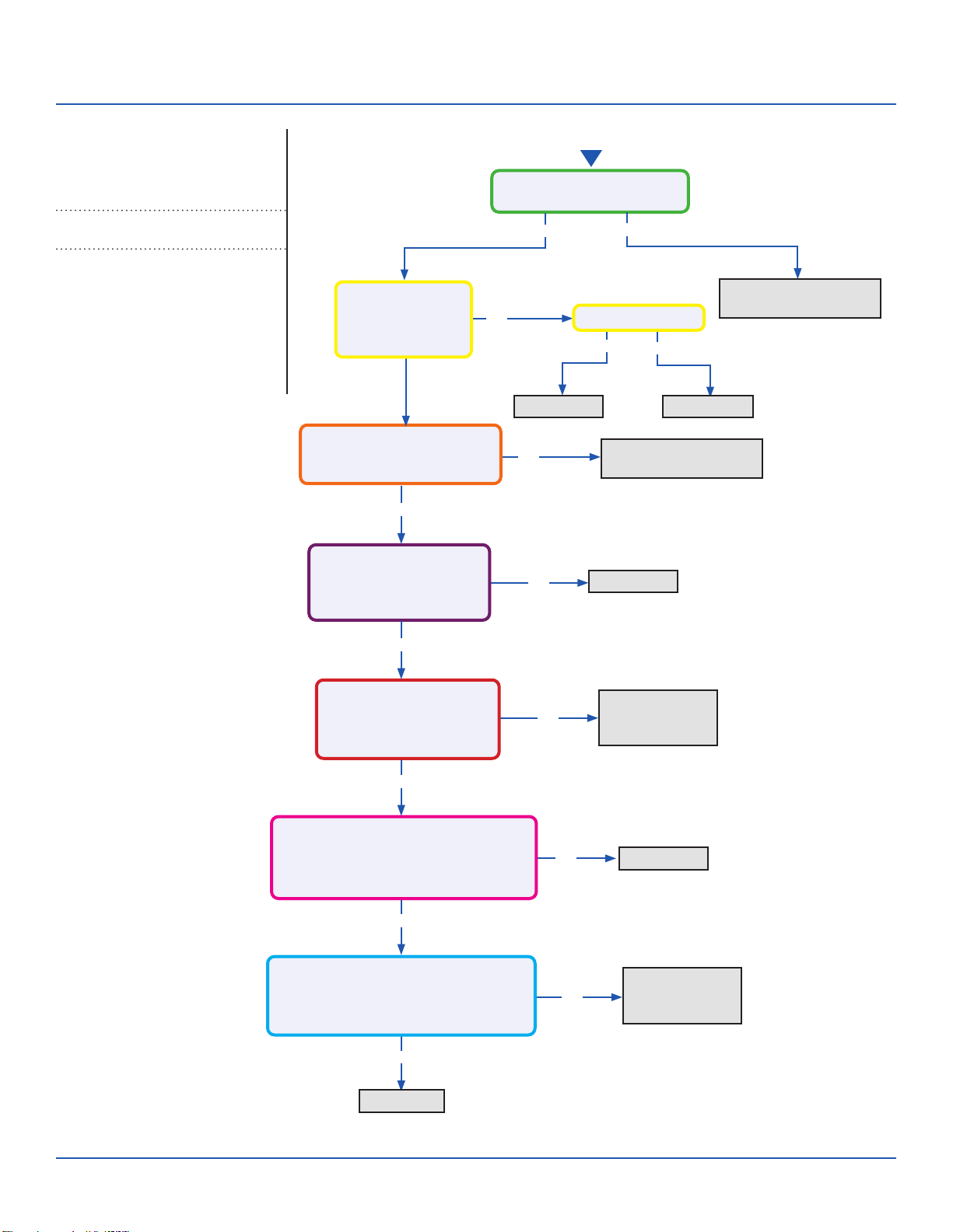
Error Code (Indoor/Outdoor)
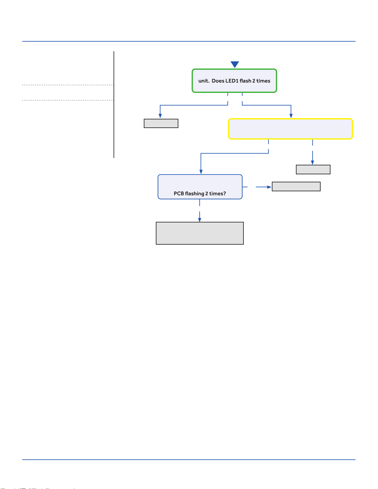
F1/LED1: 2 Flash
IPM Power Module Fail (IPM power module protection)Complete the “Check This First” Flow
Chart before continuing.
Models:
Yes
No
No
Yes
Yes No
Start
Cycle power to the outdoor
before the compressor starts?
Compressor runs for 10 min.
and stops with LED in center of
DC voltage from P-U, P-V, P-W is 150-160VDC,
DC voltage from N-U, N-V, N-W 150-160VDC?
Replace IPM
Replace IPM
Normal operation
Check coil cleanliness,
EEV operation, compressor
windings, and refrigerant charge
ERROR CODES and Troubleshooting PAGE 31
ASYW09CRAWA
ASYW12CRAWA
ASYW18CRDWA
ASYW24CRDWA
ASH109CRAWA
ASH112CRAWA
ASH118CRAWA
ASH124CRAWA
Troubleshooting
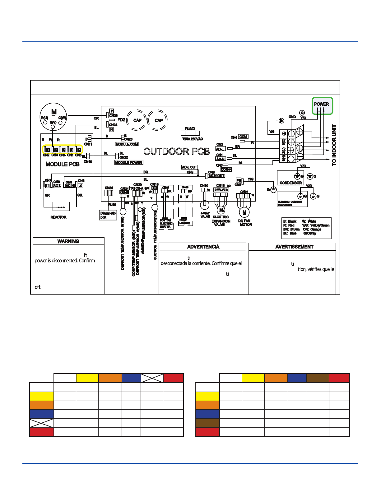
Error Code: F1/LED1: 2 Flash
Wiring Diagram Reference
OUTDOOR UNIT WIRING DIAGRAM
COMPRESSOR
Electrical Shock Hazard
Capacitor retains charge a er
voltage at capacitor has dissipated
(<10V DC) with hand held voltmeter
before servicing. LED2 light
between CN24 and CN26 should be
Riesgo de Descarga Eléctrica
El capacitor re ene carga una vez
voltaje del capacitor se haya disipado (<10V
DC) apoyando la mano sobre el vol metro
antes de realizar el servicio técnico. La luz
LED2 que se encuentra entre CN24 y CN26
deberá estar apagada.
Risque de choc électrique
Le condensateur conserve sa charge après la
coupure de l’alimenta on électrique. Avant
de procéder à une répara
courant au condensateur s’est dissipé
(<10 VCC) à l’aide d’un voltmètre manuel. Le
voyant LED2 entre CN24 et CN26 doit être
éteint.
0011509127
EEV Resistance Values
EEV (6-pin, 6 wire)
White Yellow Orange Blue Brown Red
White - OL 92 Ω OL 46 Ω OL
Yellow - - OL 92 Ω OL 46 Ω
Orange - - - OL 46 Ω OL
Blue - - - - OL 46 Ω
Brown - - - - - OL
Red - - - - - -
EEV (6-pin, 5 wire)
White Yellow Orange Blue Red
White - 92 Ω 92 Ω 92 Ω - 46 Ω
Yellow - - 92 Ω 92 Ω - 46 Ω
Orange - - - 92 Ω - 46 Ω
Blue - - - - - 46 Ω
- - - - - -
Red - - - - - -
ERROR CODES and Troubleshooting
PAGE 32
Troubleshooting
See reverse side for
wiring diagram and
relevant color-coded
test positions.
Yes
Yes No
Yes
No
No
Yes
Yes
No
No
Yes
Continue to monitor;
the system is starting
under an abnormal load
Replace IPM
Replace IPM
Check refrigerant charge
Start
The set temperature is 5°F max.
from the room temperature?
Does the error code display
before the compressor starts?
5 min and back on,
compressor exceeds
over-current point in
Service Manual?
There is pulsing 50-200
VAC at compressor
terminals U, V, and W , read
from the terminal solder
points on the IPM?
There is 264-373 VDC at
P and N on the IPM?
Change set temperature
Error Code (Indoor/Outdoor)
F2/LED1: 24 Flash
Overcurrent of the CompressorComplete the “Check This First” Flow
Chart before continuing.
Models:
ERROR CODES and Troubleshooting PAGE 33
ASYW09CRAWA
ASYW12CRAWA
ASYW18CRDWA
ASYW24CRDWA
ASH109CRAWA
ASH112CRAWA
ASH118CRAWA
ASH124CRAWA
Troubleshooting
OUTDOOR UNIT WIRING DIAGRAM
COMPRESSOR
Electrical Shock Hazard
Capacitor retains charge a er
voltage at capacitor has dissipated
(<10V DC) with hand held voltmeter
before servicing. LED2 light
between CN24 and CN26 should be
Riesgo de Descarga Eléctrica
El capacitor re ene carga una vez
voltaje del capacitor se haya disipado (<10V
DC) apoyando la mano sobre el vol metro
antes de realizar el servicio técnico. La luz
LED2 que se encuentra entre CN24 y CN26
deberá estar apagada.
Risque de choc électrique
Le condensateur conserve sa charge après la
coupure de l’alimenta on électrique. Avant
de procéder à une répara
courant au condensateur s’est dissipé
(<10 VCC) à l’aide d’un voltmètre manuel. Le
voyant LED2 entre CN24 et CN26 doit être
éteint.
0011509127
Error Code: F2/LED1: 24 Flash
Wiring Diagram Reference
ERROR CODES and Troubleshooting
PAGE 34
Troubleshooting
See reverse side for
wiring diagram and
relevant color-coded
test positions.
Yes
Yes
Yes
Start
No
No
No
No
No
Line voltage at AC-L & AC-N
on the PCB (CN2 & CN1)?
Line voltage at AC-L & AC-N
on the IPM (9K CN8 & CN9 /
12K/18K CN1 & CN2)?
Module Power voltage -
CN22 on the PCB:
Across pins 1 & 2 = 5VDC
Across pins 2 & 3 = 15VDC?
Module Power voltage -
CN10 on the IPM
Across pins 1 & 2 = 5VDC
Across pins 2 & 3 = 15VDC?
Module Com voltage - CN23 on the PCB
With a call for Heating or Cooling,
Across pins 1 & 2 = 5VDC
Across pins 2 & 3 = 15VDC ?
Module Com voltage - CN11 on the IPM
With a call for Heating or Cooling,
Across pins 1 & 2 = 5VDC
Across pins 2 & 3 = 15VDC?
Yes
Yes
Yes
No
Yes No
Yes No
Check incoming power
from building
Replace PCB
Replace PCB
Replace fuse
Replace AC-L & AC-N
wiring harness
Replace module
power wiring
harness
Replace Module
COM Wiring
Harness
Replace PCB
Replace IPM
Fuse 1 is OK?
Line voltage at
AC-L OUT & AC-N
OUT on the PCB
(CN8 & CN9)?
Error Code (Indoor/Outdoor)
F3/LED1: 4 Flash
Communication Fault Between IPM and Outdoor PCBComplete the “Check This First” Flow
Chart before continuing.
Models:
ERROR CODES and Troubleshooting PAGE 35
ASYW09CRAWA
ASYW12CRAWA
ASYW18CRDWA
ASYW24CRDWA
ASH109CRAWA
ASH112CRAWA
ASH118CRAWA
ASH124CRAWA
Troubleshooting
OUTDOOR UNIT WIRING DIAGRAM
COMPRESSOR
Electrical Shock Hazard
Capacitor retains charge a er
voltage at capacitor has dissipated
(<10V DC) with hand held voltmeter
before servicing. LED2 light
between CN24 and CN26 should be
Riesgo de Descarga Eléctrica
El capacitor re ene carga una vez
voltaje del capacitor se haya disipado (<10V
DC) apoyando la mano sobre el vol metro
antes de realizar el servicio técnico. La luz
LED2 que se encuentra entre CN24 y CN26
deberá estar apagada.
Risque de choc électrique
Le condensateur conserve sa charge après la
coupure de l’alimenta on électrique. Avant
de procéder à une répara
courant au condensateur s’est dissipé
(<10 VCC) à l’aide d’un voltmètre manuel. Le
voyant LED2 entre CN24 et CN26 doit être
éteint.
0011509127
Error Code: F3/LED1: 4 Flash
Wiring Diagram Reference
ERROR CODES and Troubleshooting
PAGE 36
Troubleshooting
Start
See reverse side for
wiring diagram and
relevant color-coded
test positions.
Yes
Yes
Yes
Yes No
No
No
Yes No
Recover refrigerant,
remove moisture and
air from system, charge
with fresh refrigerant
to nameplate amount
Check for a fan motor
issue, restricted line
set or EEV, or lack of
refrigerant
Check for a plugged coil or
refrigerant charge
Replace sensor
The discharge line temperature
is below 230°F/110°C?
The discharge sensor
ohmreading matches the
resistance table in the
Service Manual?
With system on, the
discharge sensor climbs to
230°F within a short time, and
the compressor stops?
With system on, the
discharge sensor climbs to
230°F after several minutes,
and the compressor stops?
allow the discharge line to cool
Refrigerant static test
indicates head pressure
converted to temperature is
higher than ambient?
Error Code (Indoor/Outdoor)
F4/LED1: 8 Flash
Overheat Protection For Discharge TemperatureComplete the “Check This First” Flow
Chart before continuing.
Models:
ERROR CODES and Troubleshooting PAGE 37
ASYW09CRAWA
ASYW12CRAWA
ASYW18CRDWA
ASYW24CRDWA
ASH109CRAWA
ASH112CRAWA
ASH118CRAWA
ASH124CRAWA
Troubleshooting
OUTDOOR UNIT WIRING DIAGRAM
COMPRESSOR
Electrical Shock Hazard
Capacitor retains charge a er
voltage at capacitor has dissipated
(<10V DC) with hand held voltmeter
before servicing. LED2 light
between CN24 and CN26 should be
Riesgo de Descarga Eléctrica
El capacitor re ene carga una vez
voltaje del capacitor se haya disipado (<10V
DC) apoyando la mano sobre el vol metro
antes de realizar el servicio técnico. La luz
LED2 que se encuentra entre CN24 y CN26
deberá estar apagada.
Risque de choc électrique
Le condensateur conserve sa charge après la
coupure de l’alimenta on électrique. Avant
de procéder à une répara
courant au condensateur s’est dissipé
(<10 VCC) à l’aide d’un voltmètre manuel. Le
voyant LED2 entre CN24 et CN26 doit être
éteint.
0011509127
Error Code: F4/LED1: 8 Flash
Wiring Diagram Reference
EEV Resistance Values
EEV (6-pin, 6 wire)
White Yellow Orange Blue Brown Red
White - OL 92 Ω OL 46 Ω OL
Yellow - - OL 92 Ω OL 46 Ω
Orange - - - OL 46 Ω OL
Blue - - - - OL 46 Ω
Brown - - - - - OL
Red - - - - - -
EEV (6-pin, 5 wire)
White Yellow Orange Blue Red
White - 92 Ω 92 Ω 92 Ω - 46 Ω
Yellow - - 92 Ω 92 Ω - 46 Ω
Orange - - - 92 Ω - 46 Ω
Blue - - - - - 46 Ω
- - - - - -
Red - - - - - -
ERROR CODES and Troubleshooting
PAGE 38
Troubleshooting
See reverse side for
wiring diagram, relevant
color-coded test
positions, and sensor
resistance values.
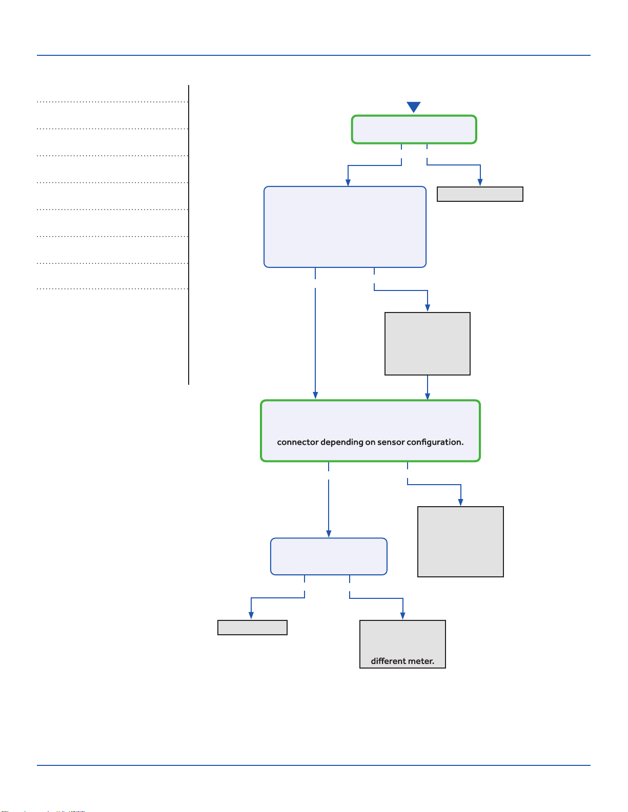
Error Codes (Indoor/Outdoor)
F6/LED1: 12 Flash
Ambient Temperature Sensor FailureF7/LED1: 11 Flash
Suction Temperature Sensor FailureF21/LED1: 10 Flash
Defrost Temperature Sensor FailureF25/LED1: 13 Flash
Discharge Temperature Sensor FailureE1/LED1: No Flash
Room Temperature Sensor FailureE2/LED1: No Flash
Indoor Coil Temperature Sensor FailureComplete the “Check This First” Flow
Chart before continuing.
Models:
Yes
Yes
Yes
Yes No
No
No
No
Re-seat connector
Replace sensor.
Go to next step
to test the board
as well before
replacing sensor.
Replace main
board. Replace
sensor as well if
resistance was
incorrect in the
previous step.
Re-seat and
re-check sensor
resistance with a
Replace sensor
Start
Is connector plugged in and
seated securely?
Disconnect power and un-plug senor
connector from the board.
Check resistance across the set of
wires for the faulting sensor. Does
the resistance correspond to the
temperature located in the respective
chart ? (See Reverse side.)
Reconnect sensor to the board and re-apply power.
Check voltage between the two corresponding
solder joints or through the top of the Molex
Is the voltage ~5VDC?
Is the temperature at the
sensor out of operating
range (+/- 3%)?
ERROR CODES and Troubleshooting PAGE 39
ASYW09CRAWA
ASYW12CRAWA
ASYW18CRDWA
ASYW24CRDWA
ASH109CRAWA
ASH112CRAWA
ASH118CRAWA
ASH124CRAWA
Troubleshooting
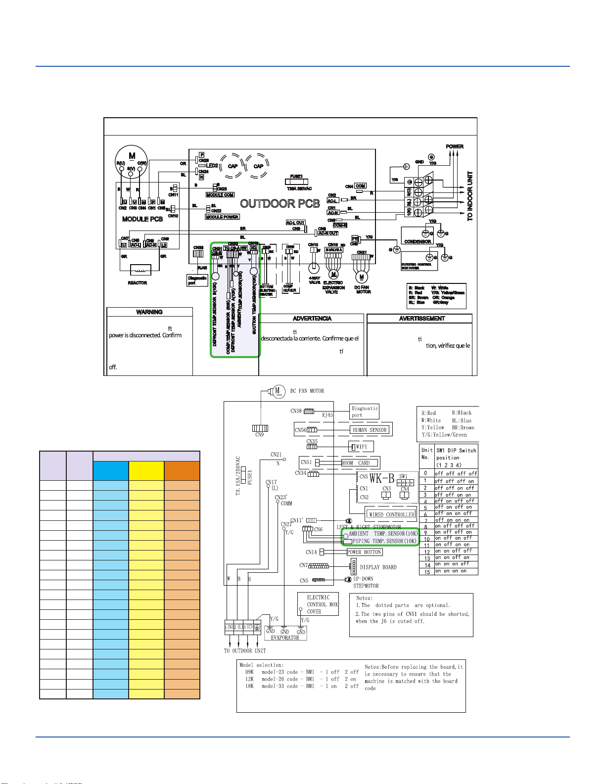
OUTDOOR UNIT WIRING DIAGRAM
COMPRESSOR
Electrical Shock Hazard
Capacitor retains charge a er
voltage at capacitor has dissipated
(<10V DC) with hand held voltmeter
before servicing. LED2 light
between CN24 and CN26 should be
Riesgo de Descarga Eléctrica
El capacitor re ene carga una vez
voltaje del capacitor se haya disipado (<10V
DC) apoyando la mano sobre el vol metro
antes de realizar el servicio técnico. La luz
LED2 que se encuentra entre CN24 y CN26
deberá estar apagada.
Risque de choc électrique
Le condensateur conserve sa charge après la
coupure de l’alimenta on électrique. Avant
de procéder à une répara
courant au condensateur s’est dissipé
(<10 VCC) à l’aide d’un voltmètre manuel. Le
voyant LED2 entre CN24 et CN26 doit être
éteint.
0011509127
Sensor Resistance Table
°F °C
Normal (KΩ
10K
SENSORS
23K
SENSORS
50K
SENSORS
-0.4 -18 75.44 235.90 5494.21
5.0 -15 64.30 196.61 4558.19
10.4 -12 54.99 164.40 3795.39
14.0 -10 49.62 146.15 3365.73
21.2 -6 40.58 115.95 2658.81
24.8 -4 36.77 103.46 2368.32
32.0 0 30.30 82.69 1887.00
35.6 2 27.55 74.07 1687.81
41.0 5 23.95 62.94 1431.28
44.6 7 21.84 56.57 1284.36
50.0 10 19.06 48.31 1094.32
55.4 13 16.68 41.40 934.94
59.0 15 15.28 37.41 843.05
64.4 18 13.42 32.22 723.41
69.8 21 11.81 27.83 622.32
75.2 24 10.42 24.11 536.65
77.0 25 10.00 23.00 511.08
80.6 27 9.21 20.95 464.05
86.0 30 8.16 18.25 402.24
89.6 32 7.54 16.67 366.13
95.0 35 6.70 14.59 318.52
100.4 38 5.97 12.79 277.70
Error Code: F6/LED1: 12 Flash, F7/LED1: 11 Flash, F21/LED1: 10 Flash, F25/LED1: 13 Flash,
E1/LED1: No Flash, E2/LED1: No Flash
Wiring Diagram Reference
ERROR CODES and Troubleshooting
PAGE 40
Troubleshooting
See reverse side for
wiring diagram and
relevant color-coded
test positions.
No
Error Code (Indoor/Outdoor)
F8/LED1: 9 Flash
Outdoor DC Fan Motor FaultComplete the “Check This First” Flow
Chart before continuing.
Models:
Yes
Yes
Yes
Yes
NoYes
No
Yes No
protection from wind.
Fix incoming power supply
Replace the fan motor
Replace the
fan motor.
Replace the
main board.
Start
Check the incoming voltage.
Is it 208/230VAC (+/- 10%) between L1/L2?
104/115VAC (+/- 10%) from L1 to GROUND and L2 to GROUND?
Does it move / rotate smoothly?
Re-apply power. Does the
fan come on and spin?
Measure DC voltage at fan motor plug
CN21 between the Pin 6 (BLUE) and Pin 3
(BLACK) wire while spinning the fan motor.
Does it generate 2~9VDC?
No
No
No
Replace the
main board.
Replace the
main board.
Replace the
main board.
Measure DC voltage at fan motor plug CN21
between Pin 1 (RED) and Pin 3 (BLACK).
Does it measure 300~380VDC (+/-10%)?
Measure DC voltage at fan motor plug CN21
between Pin 4 (WHITE) and Pin 3 (BLACK).
Does it measure between 13.5-16.5VDC?
Measure DC voltage at fan motor plug CN21
between Pin 5 (YELLOW) and Pin 3 (BLACK).
Does it measure between 2-6VDC?
Before going to the next step, is the
unit in an area susceptible to high
winds? High winds blowing into the
fan may cause added resistance
and subsequently lower fan speeds
enough to cause the unit to fault. If
this is the case the unit only faults
may need to be added.
Not Windy Windy
Yes
ERROR CODES and Troubleshooting PAGE 41
ASYW09CRAWA
ASYW12CRAWA
ASYW18CRDWA
ASYW24CRDWA
ASH109CRAWA
ASH112CRAWA
ASH118CRAWA
ASH124CRAWA
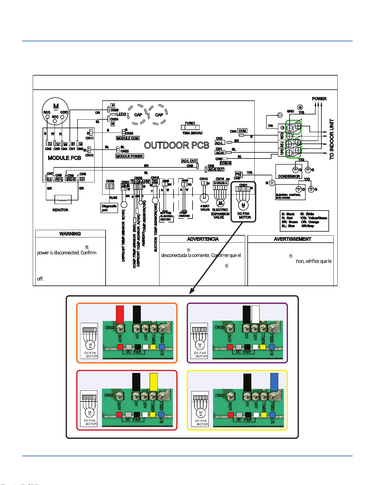
Troubleshooting
OUTDOOR UNIT WIRING DIAGRAM
COMPRESSOR
Electrical Shock Hazard
Capacitor retains charge a er
voltage at capacitor has dissipated
(<10V DC) with hand held voltmeter
before servicing. LED2 light
between CN24 and CN26 should be
Riesgo de Descarga Eléctrica
El capacitor re ene carga una vez
voltaje del capacitor se haya disipado (<10V
DC) apoyando la mano sobre el vol metro
antes de realizar el servicio técnico. La luz
LED2 que se encuentra entre CN24 y CN26
deberá estar apagada.
Risque de choc électrique
Le condensateur conserve sa charge après la
coupure de l’alimenta on électrique. Avant
de procéder à une répara
courant au condensateur s’est dissipé
(<10 VCC) à l’aide d’un voltmètre manuel. Le
voyant LED2 entre CN24 et CN26 doit être
éteint.
0011509127
Error Code: F8/LED1: 9 Flash
Wiring Diagram Reference
BLACK
BLUE
1
3
4
5
6
/
RED
BLACK
1
3
4
5
6
/
BLACK
WHITE
1
3
4
5
6
/
BLACK
YELLOW
1
3
4
5
6
/
ERROR CODES and Troubleshooting
PAGE 42
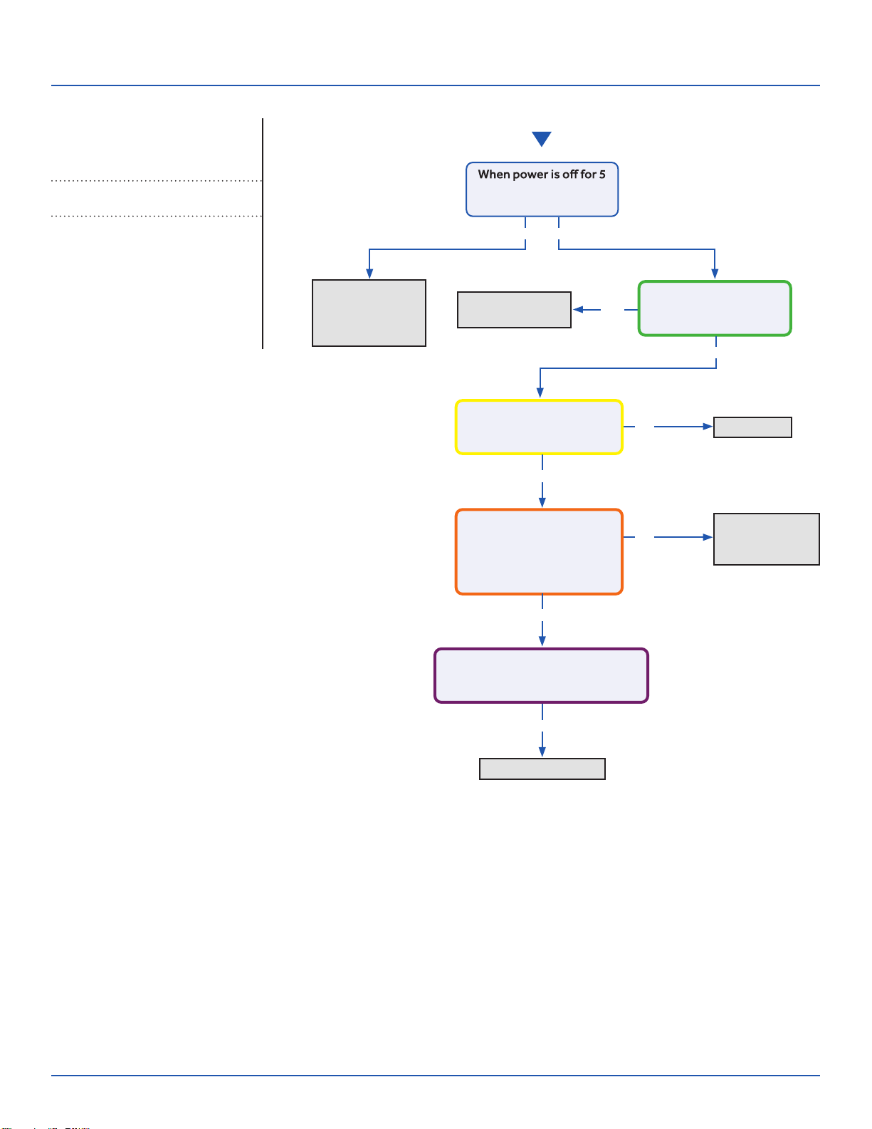
Troubleshooting
Start
See reverse side for
wiring diagram and
relevant color-coded
test positions.
No
No
Yes
Momentary loss
of building power
or acceptable
power quality
Replace
compressor
Replace compressor
Replace IPM
Repair or
replace wiring or
connections
min. and turned back on,
the compressor runs?
A windings or grounding
check shows issues with
compressor?
There is 50-200 VAC
across the U, V, and W
solder points on the IPM?
The compressor wires are
on the correct terminals,
free of breaks and the
connections at both end
are secure?
There is substantially more than
5 VDC or 15 VDC pulsing at CN23
(MODULE COM) on the PCB?
Yes
Yes
Yes
Yes
No
No
Error Code (Indoor/Outdoor)
F11/LED1: 18 Flash
Loss of Compressor SynchronizationComplete the “Check This First” Flow
Chart before continuing.
Models:
ERROR CODES and Troubleshooting PA
GE 43
ASYW09CRAWA
ASYW12CRAWA
ASYW18CRDWA
ASYW24CRDWA
ASH109CRAWA
ASH112CRAWA
ASH118CRAWA
ASH124CRAWA
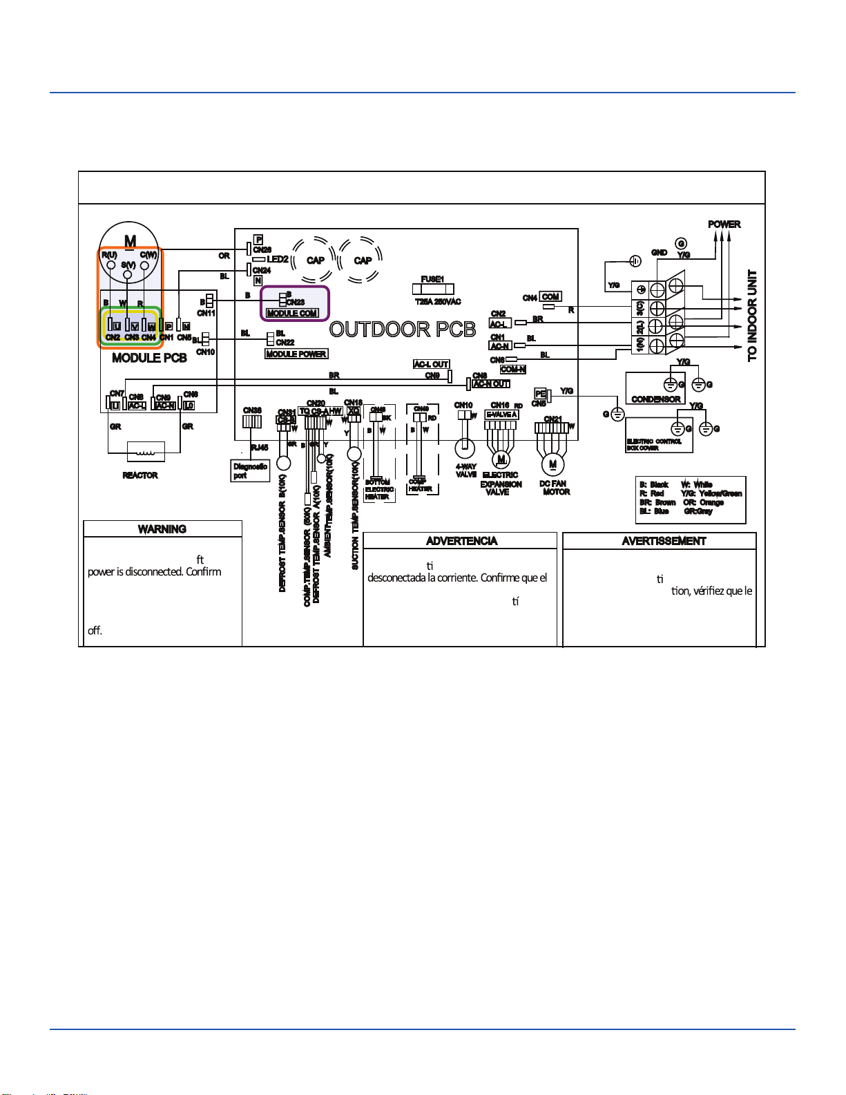
Troubleshooting
OUTDOOR UNIT WIRING DIAGRAM
COMPRESSOR
Electrical Shock Hazard
Capacitor retains charge a er
voltage at capacitor has dissipated
(<10V DC) with hand held voltmeter
before servicing. LED2 light
between CN24 and CN26 should be
Riesgo de Descarga Eléctrica
El capacitor re ene carga una vez
voltaje del capacitor se haya disipado (<10V
DC) apoyando la mano sobre el vol metro
antes de realizar el servicio técnico. La luz
LED2 que se encuentra entre CN24 y CN26
deberá estar apagada.
Risque de choc électrique
Le condensateur conserve sa charge après la
coupure de l’alimenta on électrique. Avant
de procéder à une répara
courant au condensateur s’est dissipé
(<10 VCC) à l’aide d’un voltmètre manuel. Le
voyant LED2 entre CN24 et CN26 doit être
éteint.
0011509127
Error Code: F11/LED1: 18 Flash
Wiring Diagram Reference
ERROR CODES and Troubleshooting
PAGE 44
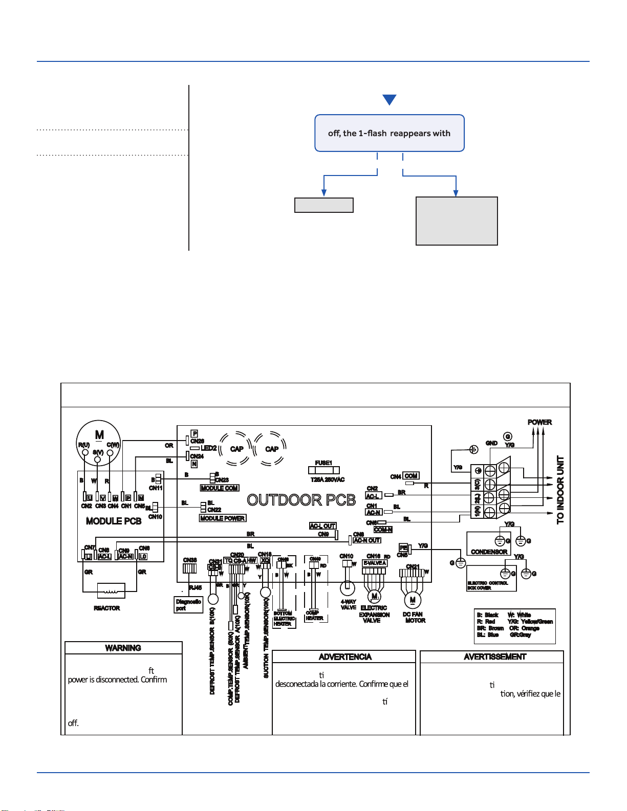
Troubleshooting
Start
See reverse side for
wiring diagram and
relevant color-coded
test positions.
Yes No
The 10-minute
reboot has
corrected the
issue
Replace PCB
After 10 minutes with the power
power turned back on?
Error Code (Indoor/Outdoor)
F12/LED1: 1 Flash
EEPROM ErrorComplete the “Check This First” Flow
Chart before continuing.
Models:
Wiring Diagram Reference
OUTDOOR UNIT WIRING DIAGRAM
COMPRESSOR
Electrical Shock Hazard
Capacitor retains charge a er
voltage at capacitor has dissipated
(<10V DC) with hand held voltmeter
before servicing. LED2 light
between CN24 and CN26 should be
Riesgo de Descarga Eléctrica
El capacitor re ene carga una vez
voltaje del capacitor se haya disipado (<10V
DC) apoyando la mano sobre el vol metro
antes de realizar el servicio técnico. La luz
LED2 que se encuentra entre CN24 y CN26
deberá estar apagada.
Risque de choc électrique
Le condensateur conserve sa charge après la
coupure de l’alimenta on électrique. Avant
de procéder à une répara
courant au condensateur s’est dissipé
(<10 VCC) à l’aide d’un voltmètre manuel. Le
voyant LED2 entre CN24 et CN26 doit être
éteint.
0011509127
ERROR CODES and Troubleshooting PAGE 45
ASYW09CRAWA
ASYW12CRAWA
ASYW18CRDWA
ASYW24CRDWA
ASH109CRAWA
ASH112CRAWA
ASH118CRAWA
ASH124CRAWA
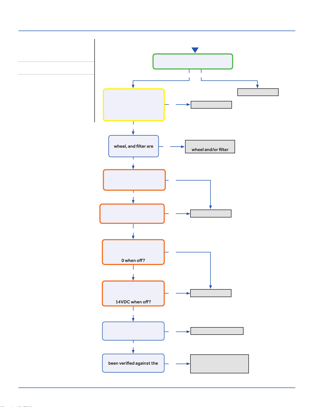
Troubleshooting
Start
See reverse side for
wiring diagram and
relevant color-coded
test positions.
Yes
Yes
Yes
Yes
Yes
Yes
Yes
No
No
No
No
No
No
No
No
Yes No
Replace PCB
Replace PCB
Replace Motor
Replace/Repair EEV Coil
Recover refrigerant, check
for leaks, evacuate, and
re-charge per nameplate
Replace sensor
Wash coil, blower
There is 5 VDC at CN6 on the Indoor
PCB across the black senor wires?
The Coil and Ambient
Sensors’ resistances are
within 3% of the value
listed in the Service Manual
sensor resistance table?
The coil, blower
free of dirt or debris?
There is DCV at the motor
PCB connections:
RD to BK: 310-334VDC?
There is DCV at the motor
PCB connections:
WH to BK: 15VDC
There is DCV at the motor
PCB connections:
YL to BK: 1-4VDC running,
There is DCV at the motor
PCB connections:
BL to BK: 4-8VDC running,
Is the EEV coil properly
seated and the coil
resistance correct?
The refrigerant charge has
nameplate value?
Error Code (Indoor/Outdoor)
E5/LED1: 22 Flash
Coil Frost ProtectionComplete the “Check This First” Flow
Chart before continuing.
Models:
ERROR CODES and Troubleshooting
PAGE46
ASYW09CRAWA
ASYW12CRAWA
ASYW18CRDWA
ASYW24CRDWA
ASH109CRAWA
ASH112CRAWA
ASH118CRAWA
ASH124CRAWA
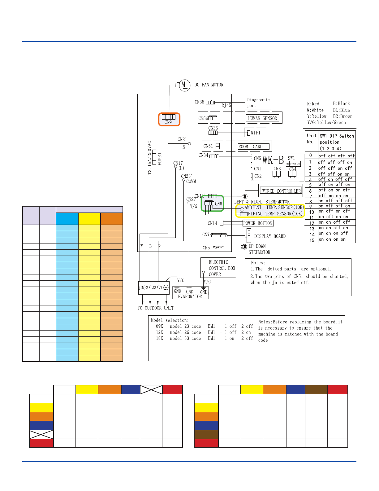
Troubleshooting
Error Code: E5/LED1: 22 Flash
Wiring Diagram Reference
Sensor Resistance Table
°F °C
Normal (KΩ
10K
SENSORS
23K
SENSORS
50K
SENSORS
-0.4 -18 75.44 235.90 5494.21
5.0 -15 64.30 196.61 4558.19
10.4 -12 54.99 164.40 3795.39
14.0 -10 49.62 146.15 3365.73
21.2 -6 40.58 115.95 2658.81
24.8 -4 36.77 103.46 2368.32
32.0 0 30.30 82.69 1887.00
35.6 2 27.55 74.07 1687.81
41.0 5 23.95 62.94 1431.28
44.6 7 21.84 56.57 1284.36
50.0 10 19.06 48.31 1094.32
55.4 13 16.68 41.40 934.94
59.0 15 15.28 37.41 843.05
64.4 18 13.42 32.22 723.41
69.8 21 11.81 27.83 622.32
75.2 24 10.42 24.11 536.65
77.0 25 10.00 23.00 511.08
80.6 27 9.21 20.95 464.05
86.0 30 8.16 18.25 402.24
89.6 32 7.54 16.67 366.13
95.0 35 6.70 14.59 318.52
100.4 38 5.97 12.79 277.70
EEV Resistance Values
EEV (6-pin, 6 wire)
White Yellow Orange Blue Brown Red
White - OL 92 Ω OL 46 Ω OL
Yellow - - OL 92 Ω OL 46 Ω
Orange - - - OL 46 Ω OL
Blue - - - - OL 46 Ω
Brown - - - - - OL
Red - - - - - -
EEV (6-pin, 5 wire)
White Yellow Orange Blue Red
White - 92 Ω 92 Ω 92 Ω - 46 Ω
Yellow - - 92 Ω 92 Ω - 46 Ω
Orange - - - 92 Ω - 46 Ω
Blue - - - - - 46 Ω
- - - - - -
Red - - - - - -
ERROR CODES and Troubleshooting PAGE 47
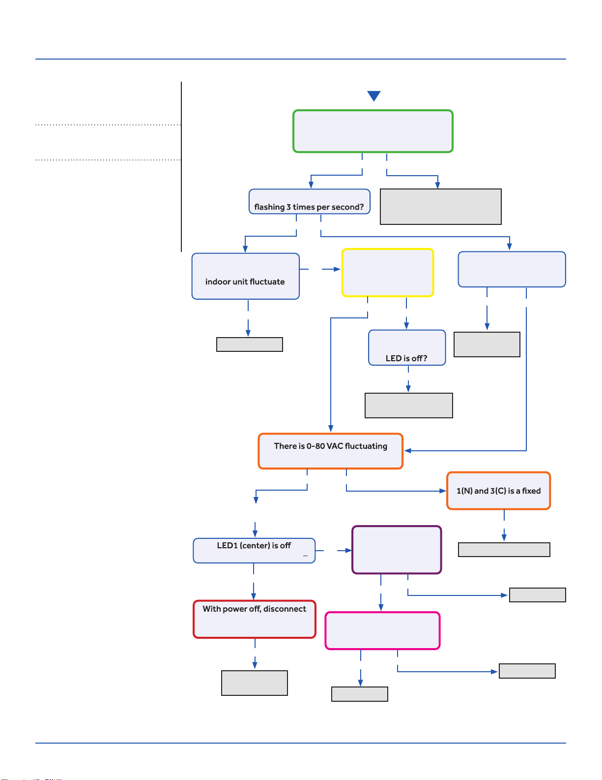
Troubleshooting
Start
See reverse side for
wiring diagram and
relevant color-coded
test positions.
Reposition on correct
terminals, replace wire if
spliced or the incorrect type
Indoor PCB OK
The control wire is 14/4 stranded
copper on the correct terminals, with
no splices or loose connections?
Yes
No
Yes
Yes
No
No
Is the Indoor PCB LED
Does the voltage
between L and C at
0~140VAC?
Is the voltage from
L to C at indoor unit
between 0~80VAC
(approx..)?
Is the Indoor PCB LED
pattern repeatedly
Flash…Flash…On?
Fault is with
outdoor PCB
Replace fan
motor
Replace INDOOR PCB
Replace PCB
Replace PCB
Replace IPM
The communication
wire is broken
between 1(N) and 3(C) at ID UNIT?
There is 230 VAC
at the PCB? Across
AC-L OUT & AC-N
OUT (CN9 & CN8)
There is less than 5 VDC at
CN22 (module power) and
GND (pins 1 and 2)?
The voltage between
value at ID UNIT?
Go to outdoor PCB
No
Yes
Yes
Yes
Yes
Yes
Yes
Yes
No
No
Yes
Yes No
No
No
LED2 (upper left) is lighted?
fan motor at CN21. LED1
lights with power back on?
The display is
lighted, yet the
Error Code (Indoor/Outdoor)
E7/LED1: 15 Flash
ID and OD Loss of Communication Complete the “Check This First” Flow
Chart for both ID and OD units before
continuing.
Models:
ERROR CODES and Troubleshooting
PAGE 48
ASYW09CRAWA
ASYW12CRAWA
ASYW18CRDWA
ASYW24CRDWA
ASH109CRAWA
ASH112CRAWA
ASH118CRAWA
ASH124CRAWA
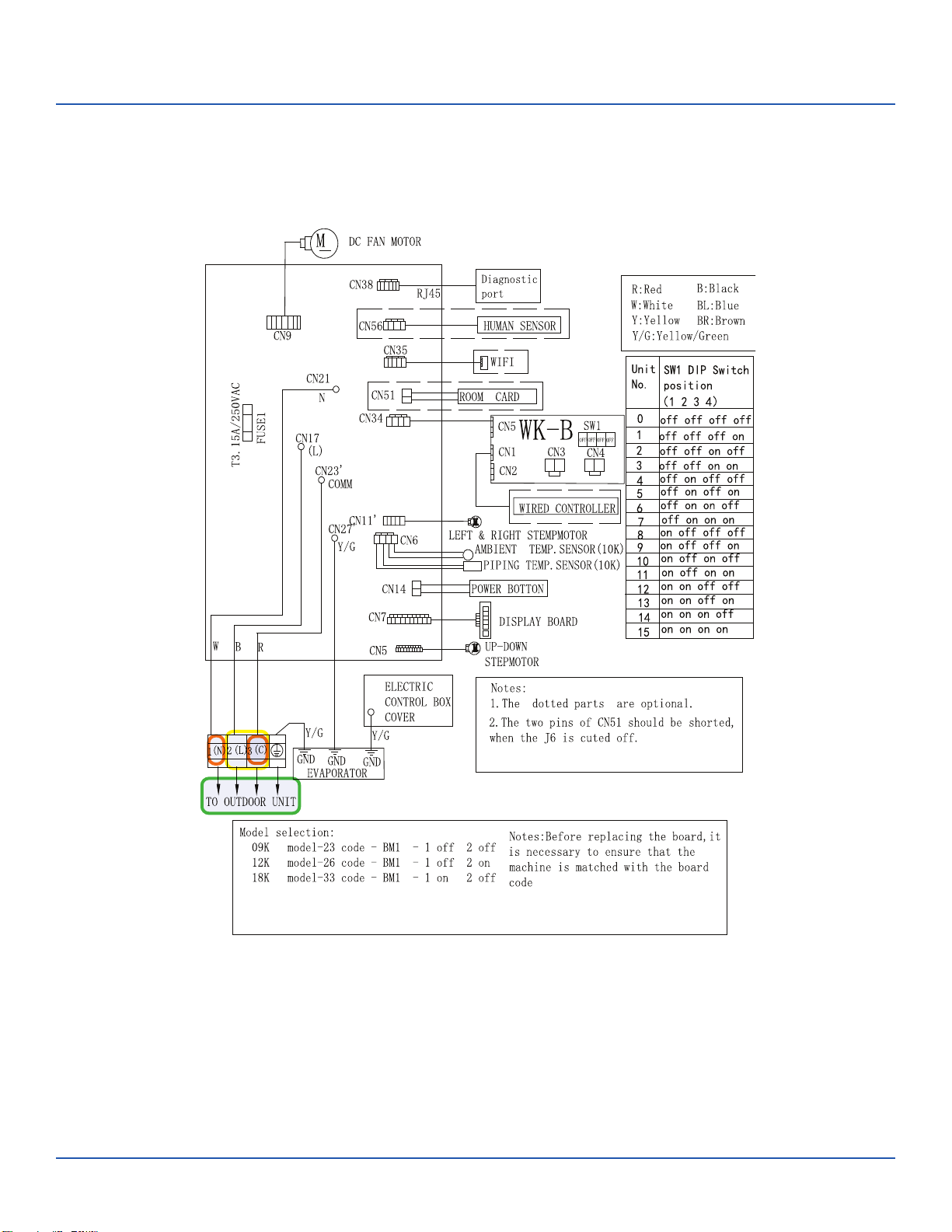
Troubleshooting
Error Code: E7/LED1: 15 Flash
Wiring Diagram Reference
ERROR CODES and Troubleshooting PAGE 49
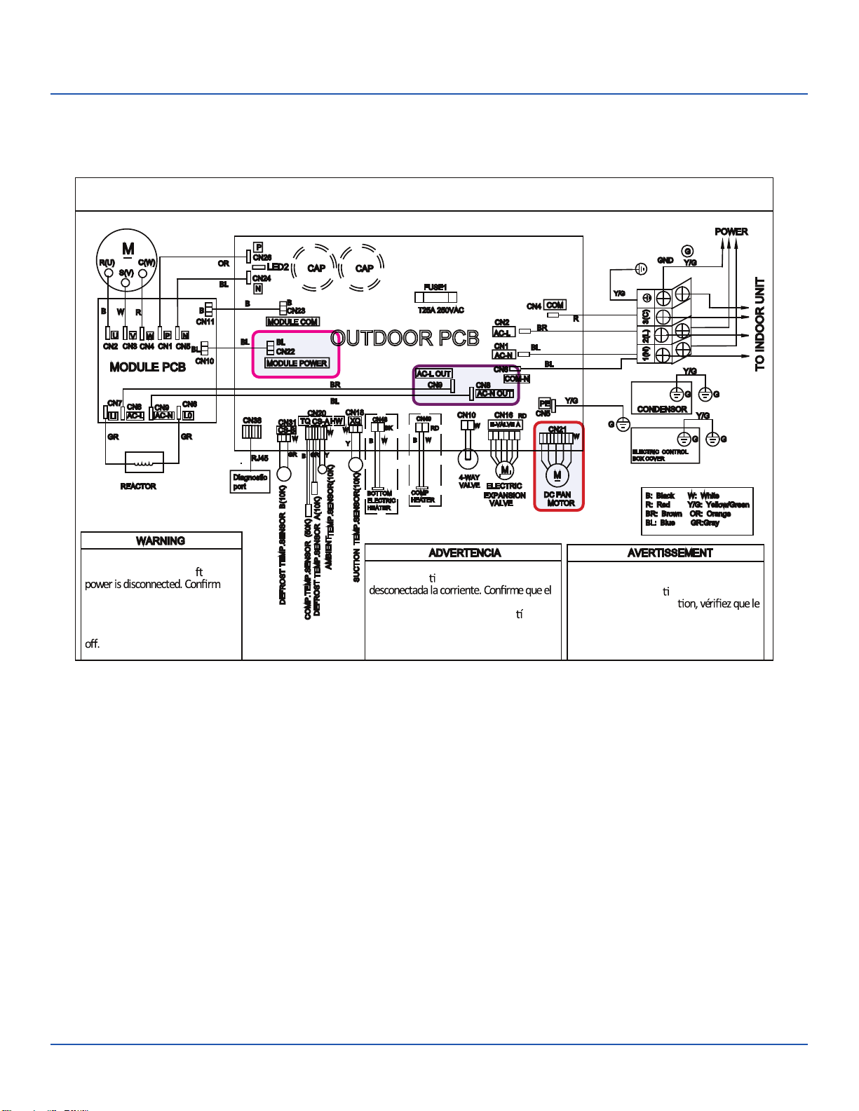
Troubleshooting
OUTDOOR UNIT WIRING DIAGRAM
COMPRESSOR
Electrical Shock Hazard
Capacitor retains charge a er
voltage at capacitor has dissipated
(<10V DC) with hand held voltmeter
before servicing. LED2 light
between CN24 and CN26 should be
Riesgo de Descarga Eléctrica
El capacitor re ene carga una vez
voltaje del capacitor se haya disipado (<10V
DC) apoyando la mano sobre el vol metro
antes de realizar el servicio técnico. La luz
LED2 que se encuentra entre CN24 y CN26
deberá estar apagada.
Risque de choc électrique
Le condensateur conserve sa charge après la
coupure de l’alimenta on électrique. Avant
de procéder à une répara
courant au condensateur s’est dissipé
(<10 VCC) à l’aide d’un voltmètre manuel. Le
voyant LED2 entre CN24 et CN26 doit être
éteint.
0011509127
Error Code: E7/LED1: 15 Flash
Wiring Diagram Reference
ERROR CODES and Troubleshooting
PAGE 50
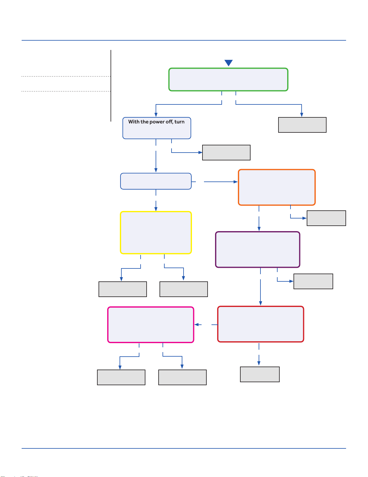
Troubleshooting
See reverse side for
wiring diagram and
relevant color-coded
test positions.
Error Code (Indoor)
E14
Indoor Fan Motor Failure Complete the “Check This First” Flow
Chart before continuing.
Models:
Yes
Yes
Yes
Yes
No
Yes No
No
Fix incoming
power supply
Replace the fan
motor
Replace the main
board.
Replace the fan
motor
Replace the
main board.
Replace the
main board.
Replace the
main board.
Start
the fan by hand. Does it
move / rotate smootly?
Check the incoming voltage. Is it 208/230VAC
(+/- 10%) between L1/L2? 104/115VAC (+/-
10%) from L1 to GROUND and L2 to GROUND?
Re-apply power. Does the
fan come on and spin?
Measure DC voltage at fan
motor plug CN9 between
the Pin 7 (BLUE) and Pin
4 (BLACK) wire while
spinning the fan motor.
Does it generate 2~9VDC?
Measure DC voltage at fan
motor plug CN9 between Pin
1 (RED) and Pin 4 (BLACK).
Does it measure 300~380VDC
(+/-10%)?
Measure DC voltage at fan motor
plug CN9 between Pin 5 (WHITE)
and Pin 4 (BLACK).
Does it measure between
13.5-16.5VDC?
No
No
No
Yes
Replace the main
board.
Replace the fan
motor
Measure DC voltage at fan
motor plug CN9 between Pin 6
(YELLOW) and Pin 4 (BLACK).
Does it measure between
2-6VDC?
Measure DC voltage at fan motor
plug CN9 between the Pin 7
(BLUE) and Pin 4 (BLACK) wire
while spinning the fan motor.
Does it generate 2~9VDC?
No
Yes No
Yes
ERROR CODES and Troubleshooting PAGE 51
ASYW09CRAWA
ASYW12CRAWA
ASYW18CRDWA
ASYW24CRDWA
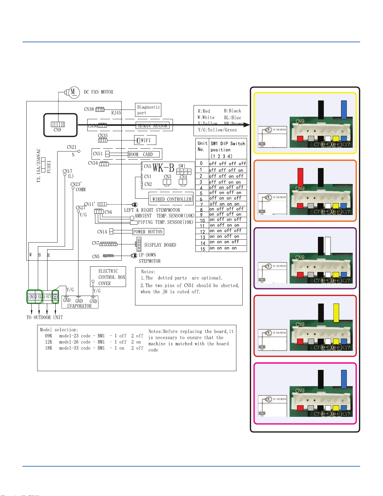
Troubleshooting
Error Code: E14
Wiring Diagram Reference
BLACK
BLUE
1
4
5
6
/
7
BLACK
1
4
5
6
/
7
RED
BLACK
1
4
5
6
/
7
WHITE
BLACK
1
4
5
6
/
7
YELLOW
BLACK
BLUE
1
4
5
6
/
7
ERROR CODES and Troubleshooting
PAGE 52
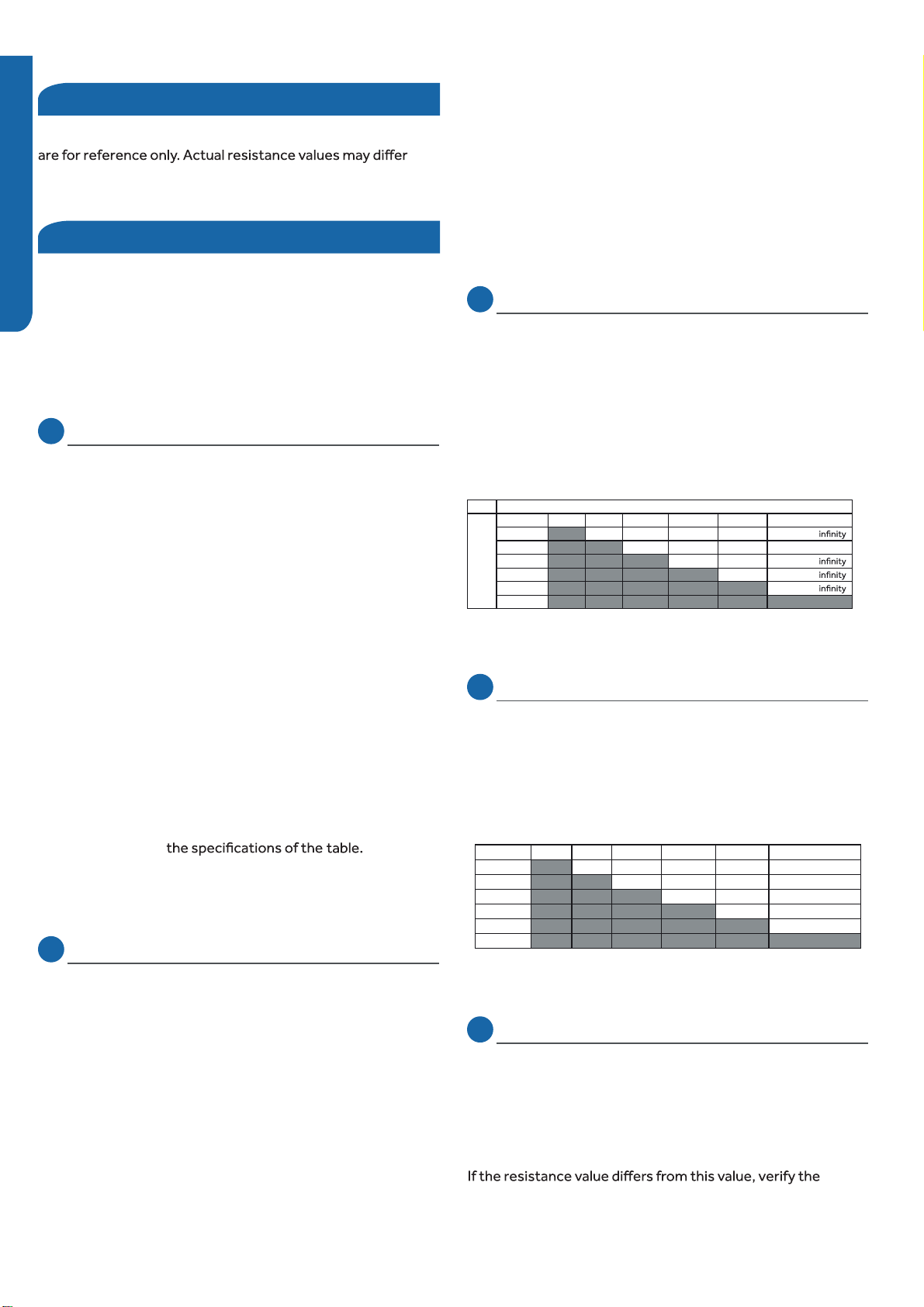
ENGLISH
Checking System Components
Checking Outdoor Unit Components
Checking the DC Fan Motor
Red Test Lead
Black
Test
Lead
Red --- Black White Yellow Blue
Red --- 3.10Meg 3.05Meg 3.28 Meg Charges to
---------------
ot segrahCK1.541K58.34kcalB
ot segrahCK0.981etihW
ot segrahCwolleY
Blue
Checking the EEV Stepper Motor
White Yellow Orange Blue Red Grey
White --- 92.6Ohm --- 47.0 Ohm ---
hO 1.39---wolleY m 47.0 Ohm
---mhO 5.64egnarO
mhO 8.64eulB
---deR
Grey
Checking the PFC Reactor
Checking the Outdoor Unit Sensors
Checking the Reversing Valve Coil
NOTE: Component resistance readings shown in this section
based on model being tested.
Testing of the following components requires the use of an
ohmmeter and temperature probe.
NOTE: Use needle probes only, and probe the back or side
contacts of the plug to obtain the reading. Do not try to
probe the connector end of the plug, as this may damage the
contacts of the plug.
NOTE: Use respective temperature / sensor chart for sensor
type being tested.
Compressor discharge sensor
Suction sensor
Tube sensor (defrost temperature)
Ambient sensor
Step 1
Disconnect the sensor plug from the control board for this
test. Failure to do so may provide inaccurate readings.
Step 2
k-type temperature probe, determine the temperature of
the sensor.
Step 3
Using an ohmmeter, check the resistance value of the sensor.
Step 4
Referring to the temperature / resistance table specific table,
verify the resistance value corresponds to the temperature
shorted, or outside
Step 5
Re-seat the plug on the connector at the conclusion of the
test.
Step 1
Disconnect the reversing valve plug from the control
board connector for this test. Failure to do so may provide
inaccurate readings.
Step 2
Step 3
Re-seat the plug on the connector at the conclusion of the
test.
Step 1
Disconnect the DC Fan Motor plug from the control board
connector for this test. Failure to do so may provide
inaccurate readings.
Step 2
Refer to the chart shown below for plug pin combinations and
resistance values.
Note: Test is polarity sensitive, adhere to probe placement as
shown in chart.
Step 3
Re-seat the plug on the connector at the conclusion of the
test.
Step 1
Disconnect the EEV Stepper Motor plug from the control
board connector for this test. Failure to do so may provide
inaccurate readings.
Step 2
Refer to the chart shown below for plug pin combinations and
resistance values.
Step 3
Re-seat the plug on the connector at the conclusion of the
test.
Step 1
Disconnect wires from terminals LI and LO of the power
module board.
Step 2
Using an Ohmmeter, check the resistance value of the PFC
Reactor. The resistance value of the coil is less than 1 Ohm.
checked in step 2.Replace the sensor if the reading is open,
Using an ohmmeter, test the coil to make sure it is not open,
shorted, or grounded. The 09k and 12k models have a four way
units normally found in mini-split systems.Rather than the
voltage applied to the valve coil remaining as long as the call for
heat is active, the Tempo 115 VAC models apply momentary
valve (4WV) that operates differently from the standard 230 VAC
power in the 103 to 126 VAC range. This power remains long
enough to switch the valve piston from cooling to heating mode.
Since the refrigerant pressure flowing from the valve body
capillary tube holds the piston in place, allowing hot gas to
redirect into the indoor coil, the VAC signal is no longer needed
and is removed by the PCB.18k and 24k models will read
230 VAC across the coil as long as the unit is in the heating
(energized) mode.
PAGE 5
3
ERROR CODES and Troubleshooting
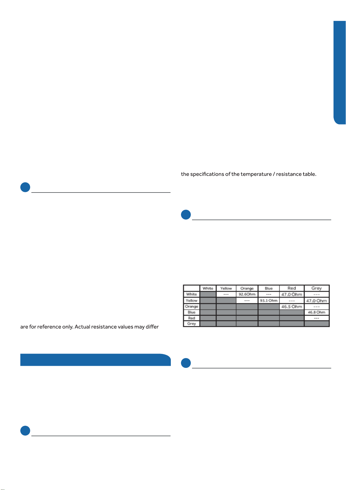
ERROR CODES AND PROBLEM SOLVING
PAGE 54
ENGLISH
Checking the Compressor Windings
Checking the Up/Down Stepper Motors
Checking the Left/Right Stepper Motors
Checking Indoor Unit Components
Checking the Indoor Unit Sensors
wiring and connections to the PFC Reactor as well as the PFC
Reactor itself. Repair or replace as necessary.
Step 3
Reconnect the wiring to the module board at the conclusion
of the test.
Step 1
Disconnect the Socket Protect plug from the control
board connector for this test. Failure to do so may provide
inaccurate readings.
Step 2
Using an ohmmeter, check the resistance value of the Socket
Protect component. The resistance reading should be 0
Ohms. If it is not, replace the component.
Step 3
Re-seat the plug on the connector at the conclusion of the
test.
Step 1
Disconnect wiring from terminals U (black wire), V (white
wire), and W (red wire) of the power module board.
Step 2
Using an ohmmeter, check the resistance value of the
compressor windings. Measure between wires U (black wire)
and V (white wire), U (black wire) and W (red wire), and V
(white wire), and W (red wire).
The resistance value of the windings should be balanced
(equal). If the resistance values are not equal, verify the
wiring and connections to the compressor as well as the
compressor itself. Repair or replace as needed.
Step 3
Reconnect the wiring to the module board at the conclusion
of the test.
NOTE: Component resistance readings shown in this section
based on model being tested.
Testing of the following components requires the use of an
ohmmeter and temperature probe (Temperature probe is
used during sensor testing only).
NOTE: When using the test probes, probe the back or side
contacts of the plug to obtain the reading. Do not try to
probe the connector end of the plug as this may damage the
contacts of the plug.
NOTE: Use respective temperature / sensor chart for sensor
type being tested.
Coil sensor
Ambient sensor
Step 1
Disconnect the sensor plug from the control board for this
test. Failure to do so may provide inaccurate readings.
Step 2
Using a temperature probe, determine the temperature of
the sensor being tested.
Step 3
Using an ohmmeter, check the resistance value of the sensor.
Step 4
Referring to the temperature / resistance table for the sensor
being checked, verify the resistance value corresponds to the
temperature checked in Step 2.
Replace the sensor if the reading is open, shorted, or outside
Step 5
Re-seat the plug on the connector at the conclusion of the
test.
Step 1
Disconnect the Up/Down Stepper Motor plug from the
control board connector for this test. Failure to do so may
provide inaccurate readings.
Step 2
Refer to the chart shown below for plug pin combinations and
resistance values.
Step 3
Re-seat the plug on the connector at the conclusion of the
test.
Step 1
Disconnect the Left Stepper Motor plug from the control
board connector for this test. Failure to do so may provide
inaccurate readings.
Step 2
Refer to the chart shown below for plug pin combinations and
resistance values.
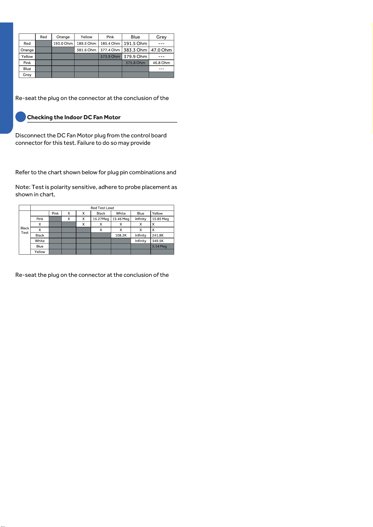
ERROR CODES AND PROBLEM SOLVING PAGE 55
ENGLISH
Step 3
test.
Step 1
inaccurate readings.
Step 2
resistance values.
Lead
Step 3
test.

REFERENCE INFORMATION
PAGE 56
ENGLISH
Reference Information
Table of Contents
Outdoor Board Diagram ................................................................................................................................................... 57
Outdoor Board Schematic ................................................................................................................................................ 58
Indoor Board Diagram ...................................................................................................................................................... 62
Indoor Board Schematic ................................................................................................................................................... 63
Module Board Schematic .................................................................................................................................................. 65
Room and Pipe Sensor Tables ........................................................................................................................................... 66
Ambient, Defrost and Pipe Sensor Tables .......................................................................................................................... 69
Discharge Sensor Tables .................................................................................................................................................. 73
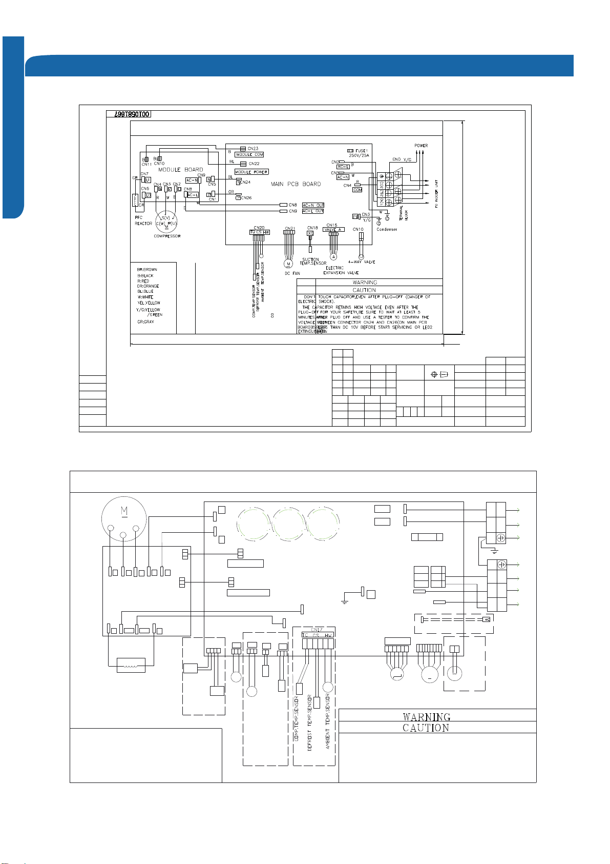
REFERENCE INFORMATION PAGE 57
Outdoor Board Diagram
&1&1&1&1&1&1&1&1&15869&:
:5
028'/(3&%89:31&2035(6625%˖%/$&.<*˖<(//2:*5((1:˖:+,7(25˖25$1*(%/˖%/8(5˖5('
$&1287&1&1$&/287&1:$<9$/9(0&1&19$/9($&13(
32:(5
%/RU:<*
&1&20%&20$1
5
&1&1$&1$&/)86(7$9$&&1&102'8/(&2002'8/(32:(5
72,1'22581,7
&1%%/
%/25
&15($&725
%%
'&)$1
287'2253&%
(/(&75,&(;3$16,21
<*
<*
1/&
%/RU:%/
$&//,$&1/
&113&1
1/
::%5RU%
&$309$/9(02725127(67+('277('3$576$5(237,21$/#
and @2 cannot exist at
the same time but must
keep one of them.
287'22581,7:,5,1*',$*5$0&$3&$3
'217728&+&$3$&,725(9(1$)7(53/8*2))'$1*(52)(/(&75,&6+2&.
7KHFDSDFLWRUUHWDLQVKLJKYROWDJHHYHQDIWHUWKHSOXJRII)RU\RXUVDIHW\EHVXUHWRZDLWDWOHDVWPLQXWHVDIWHUSOXJRIIDQGXVHDWHVWHUWRFRQILUPWKHYROWDJHEHWZHHQFRQQHFWRU3DQG1LVOHVVWKDQ'&9EHIRUHVWDUWVHUYLFLQJ
&1&1$&1287$&/287
%5RU%
$$&*$;*$3,3,1*&1&17&
&2037(036(1625'()52677(036(1625
&6&1
$0%,(177(036(1625
+:&1
68&7,217(036(1625
4;&17(036(1625
%/RU:%/25:%525%
CN50 '5('OLQH
##
ᴯᦒᕐᔪ䳴㪓ᲃ㦹䜝Ӟ䜝㘰ߜࡈ㚊、儈ᒣ
4+5
нᒢ㜦ঠࡧ૱
52+6
W
287'225:,5,1*',$*5$0
%
䜘૱〠ᖒᔿᣅᖡ⌅仌㢢ޘ⺜ቲ␡㺘䶒༴⨶✝༴⨶㺘䶒⺜ᓖᶀᯉᰕᵏᶀᯉቪረ
3(7
ᴤ᭩Ӫᴤ᭩᮷Ԧ䜘૱䘲⭘ḷ߶4+.7-∄ֻ䍘䟿Jᵚ⌘ޜᐞ䘲⭘ḷ߶
ཆ㓯䐟മ
$%6
മṧḷ䇠ᇑᇊḷ߶ᰕᵏޡᕐㅜᕐമ⽪ԕཆһ亩᤹4+.7-䶂ዋ⎧ቄオ䈳ಘᴹ䲀ᙫޜ
%
8%8(5(8%8(5(
㺘䶒㋇㌉ᓖ˖⡸⅑ḷ䇠༴ᮠㆮᆇᓅമᙫᇑṨṑሩ䇮䇑ᐕ㢪ᰕᵏḷ䇠
ᢰᵟ㾱≲˖ǃ仌㢢ǃ⡸䶒䇮㖞ㅖḷ߶˗ǃ⡸䶒Რᰐ⊑⢙˗ǃঠࡧᆇփᲠ˗ǃᡰᴹ亩ѪᗵỰ亩˗ǃᴹᇣ⢙䍘ᓄㅖḷ߶
4+5
઼
4+5
Ⲵޣ㾱≲DŽ
4+5
9-12K
9-12K
K
ENGLISH
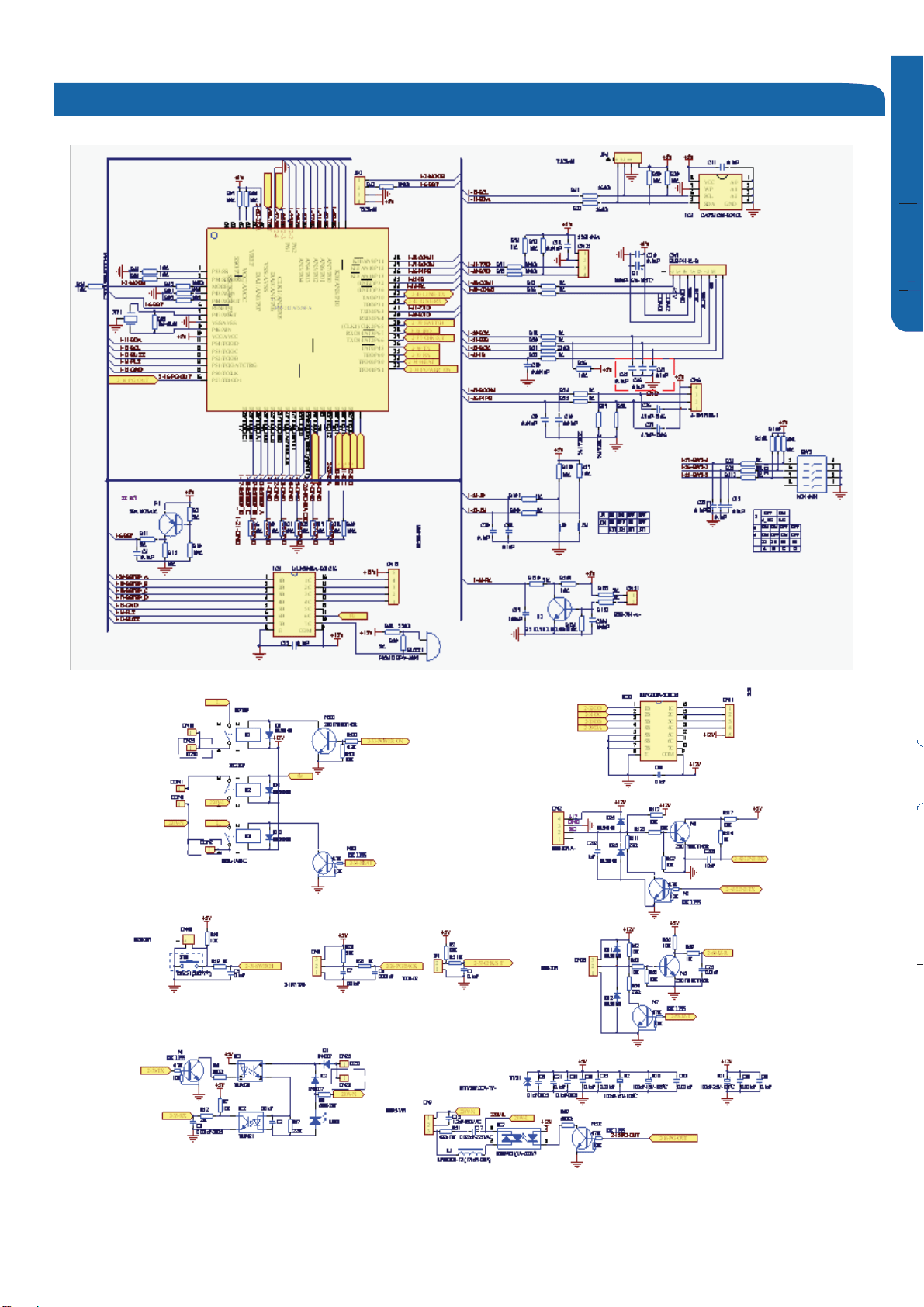
REFERENCE INFORMATION
PAGE 58
ENGLISH
Outdoor Board Schematic
9-12K
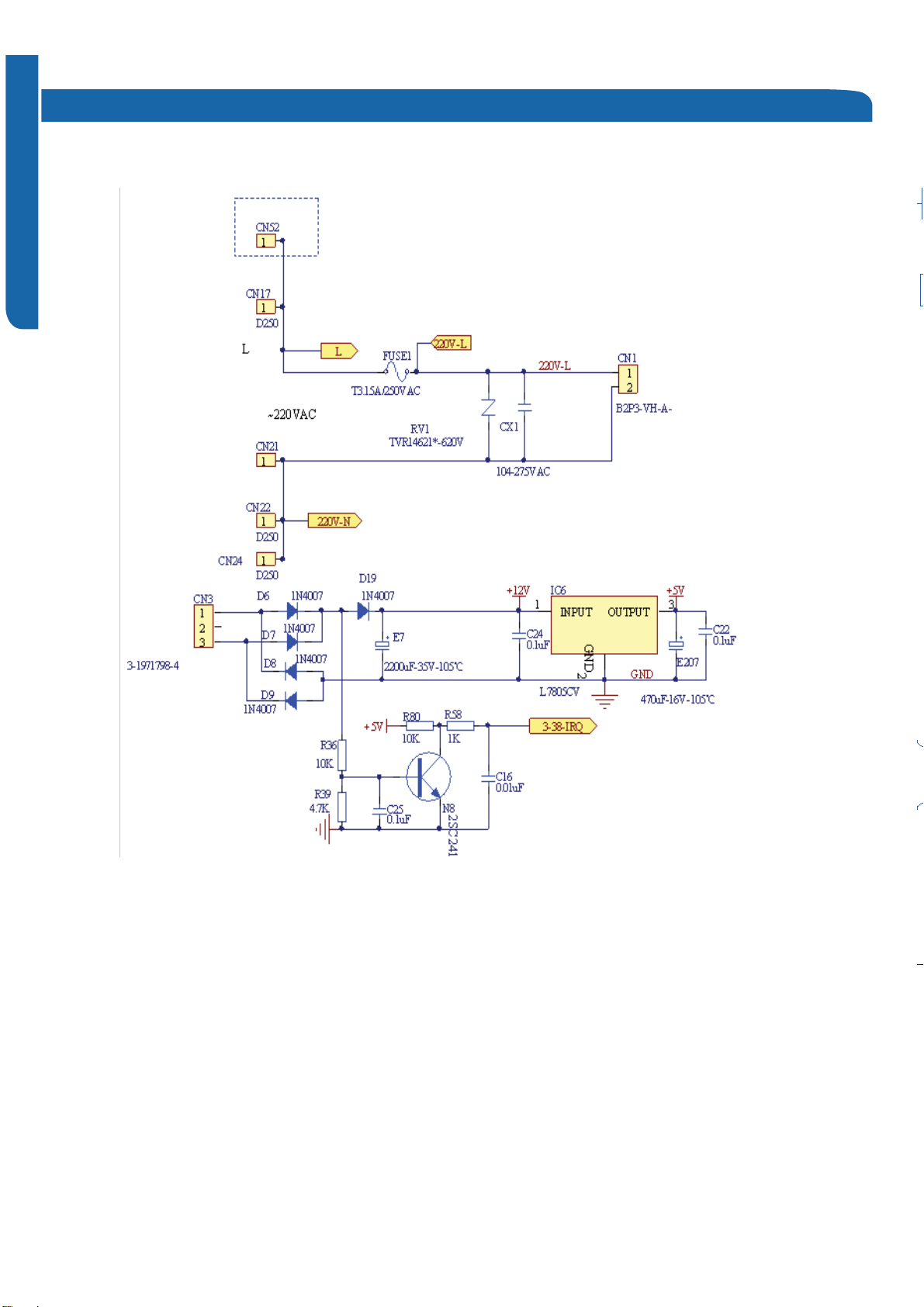
REFERENCE INFORMATION PAGE 59
Outdoor Board Schematic
Outdoor Board Schematic
ENGLISH
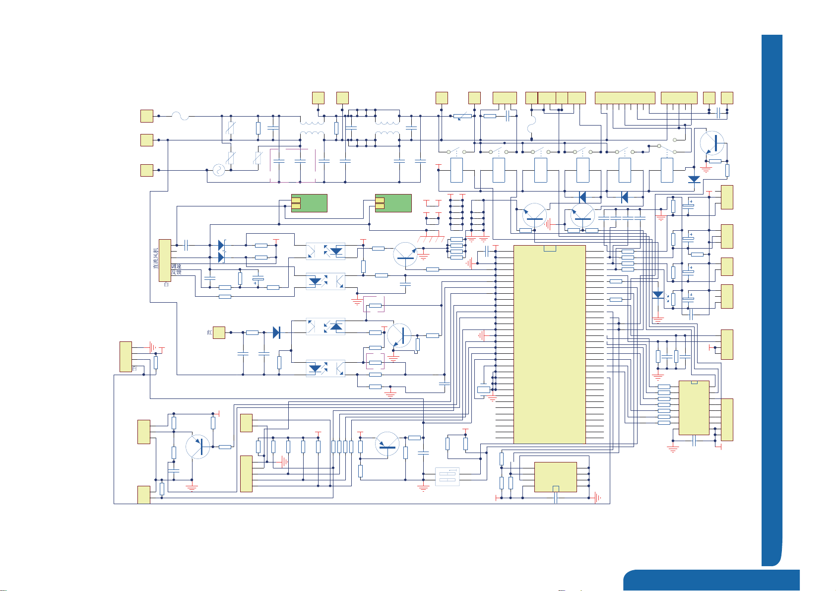
REFERENCE INFORMATION
PAGE 60
ENGLISH
Outdoor Board Schematic
() g g
11.2.Outdoor Unit
11.2.1Control Board Circuit Diagrams
13
GND 4
GND 3
GND 2
GND 1
VCC
8GND
7SCL
6SDA
5
IC6 AT24C02B
1
CN2
AC-L
1
CN1
AC-N
Black
White
FUSE1
T25A 250VAC RV1
S14K350
R1
1M
R12
100/1W
CX1
225/275V
L1
8MH/10A
RV2
S14K350
RV3
S14K350
CX2
225/275V
PTC1
400N
CY1
472/250V/275V
CY2
472/250V/275V
CY3
103/250V/275V
CY4
103/250V/275V
1
CN3
PE
SA1
RA-362M
K5
12V-25A-891P-1A-C
K3
12V-5A-892H(N)-1AC-C
K4
12V-5A-892H(N)-1AC-C
K2
12V-5A-892H(N)-1AC-C
K1
12V-5A-892-1CC-C
1
2
3
CN10
Comment:
CX4
103/275V
1
2
3
4
5
6
7
8
9
CN12
1
2
3
4
5
CN13
STCOM
1
CN14
1
CN15
C1
2U/450V
COM L H C C COM L H CC
1
2
3
4
5
6
7
GND 12V
10
11
12
13
14
15
16
IC7 ULN2003
+12V
1
2
3
4
5
6
CN16
A
B
C
D
C10
104/50V
+5V
+5V
R75 2K
LED1
P1
2SA1037AK
R47
5.1K/1%
R49
10K
R50
1K
+5V
C20
102/50V
1
2
3
4
5
6
CN21
C15
103/50V
310V
0V
15V
R33
2.2K
R36 1K
R34 1K
R13 330/1W
R35 1K
R37 330
ZD2
10V/0.5W
ZD3
5.1V/0.5W
4
3
1
2
IC8
PC817A
4
3
1
2
IC9
PC817A
E9
47U/25V
N1
Comment: 2SC2412K
R41 1K
R39
10K
R38
330
R40 5.1K/1%
C14
102/50V
XT1
4M
C13
104/50V
+5V
C12
104/50V
R63
560
R65
10K
R64
10K
1
2
3
CN20
1
2
3
CN18
1
2
CN19
+5V
R76
20K/1%
R87
4.7K
R88
10K
R771K
C24
104/50V
C25
104/50V
C26
104/50V
E14
4.7U/16V
E11
4.7U/16V
E12
4.7U/16V
E13
4.7U/16V
+15V
R74 10K/1%
R73 10K/1%
R54
10K
C22 102/50V
C21 102/50V R82
47K/1%
R80
20K/1%
R78
20K/1%
R791K
R811K
R831K
C23
104/50V
CS(White) )etih W ( Q T)w olleY( W H
1
2
3
CN23
5V
COM
GND
Com with Module (Black)
1
2
3
4
5
CN30
1
2
3
4
CN31
+5V
1
CN8
AC-N OUT
1
CN9
AC-L OUT naF C A deeps-oya W - ruo F
E-valve(White)
R55 1K
R56 1K
R57 1K
R58 1K
R67 1K
R72 1K
R71 1K
R70 1K
+5V
1
2
CN33
SW TEST(BLUE)
CX7
104/275V
R48
10K
XQ(Red)
C11
104/50V
R62
10K
P2
2SA1037AK
R60
10K
R61
2K
R59
2K
FUSE2
T1A/250V
WB
R53
10K
R52
10K
R51
10K
FUCTION TEST(White)
TEST/SS
COOL
HEAT
PC
GND
( )
+5V
R85
10K
R66 1K
R84
4.7K
R68 1K
R69 1K
N3
2SC2412K
N4
2SC2412K
White
ERROR
1
2
3
CN17
D5
LL4148
D6
LL4148
Yellow/Green
1
2
CN32
TEST/SS
GND
1
2
CN11
+12V
J1
J2
J3
J6
+5V +5V
J7
+12V+12V
J8
R91
10K
J9
J10
C19
104/50V
J15
J16+15V+15V
J13
J14
J12
R92 0
R93 0
R94 0
J17
J19
J23
L2
8MH/10A
R2
1M CX3
225/275V
CY5
472/250V/275V
CY6
472/250V/275V
J24 J25 J26 J27
J28 J29 J30 J31
J32
J33
N
P
P
N
1
2
CN36
White Black
R86
4.7K
K6
12V-5A-892H(N)-1AC-C
D11
LL4148
N5
2SC2412K
R89
10K
J27
J34
1
2
4
3
SW1
R95
10K
R96
10K
+5V
VCC
62
VREF
61
AVSS
59
DC-FANSPEED
13
DC FAN PG
36
Indoor Com OUT
41
Indoor Com IN
38
PC COM
37
NC 33
Terminal Pro
28
MODULE COMOUT
27
MODULE COM IN
26
VSS
50 TEST-EN
24 NC
44
COOL-EN
23
HEAT-EN
22
RESET
6
XIN
9
XOUT
7
VSS
8E-VALVE-A 5
E-VALVE-B 4
E-VALVE-C 2
E-VALVE-D 1
PTC 64
HEAT-1 63
4-WAY 58
FAN 57
H/L FAN SPEED 42
SCL 30
SDA 29
Fan/E-Valve select 47
HEAT-2 60
VSS
49 VSS
48
Fault Light 31
Fre Adjust 46
HW 54
CS 53
XQ 52
TX 51
NC
45
MODE 3
VCC
10
NC
14
NC
15
NC
17
NC
18
NC
19
NC
20
NC
21
NC
25 NC 11
NC 12
NC 16
NC 32
NC 34
NC 35
NC 40
NC 39
NC 43
SW-2 56
SW-1 55
IC5
R5F212A8SNFA
1
2
3
4
CN7
R98
10K
+5V
MODE
RST
5V
GND
FLASH
R97
10K
R46
0
1
CN5
AC-L
1
CN6
AC-N
J4
J5
J22
J35
J36
J37
J38
R99 0
J39
J40
CY7
222/250VAC
R4
2K
CY10
222/250VAC
C16
Comment: 102/50V
+5V
R42
330
R3
2K/2W
D1
1N4007
4
3
1
2
IC11
TLP851/PC851
R43
0
R44
1K
4
3
1
2
IC10
TLP421/PS2561
1
CN4
COM
J18
J21
J20
1
CN25
1
CN27
COM heater
N6
Comment: 2SC2412K
R100
4.7K
R101
4.7K
R102
0
R103
4.7K
R104
0
R19
47
18-24K
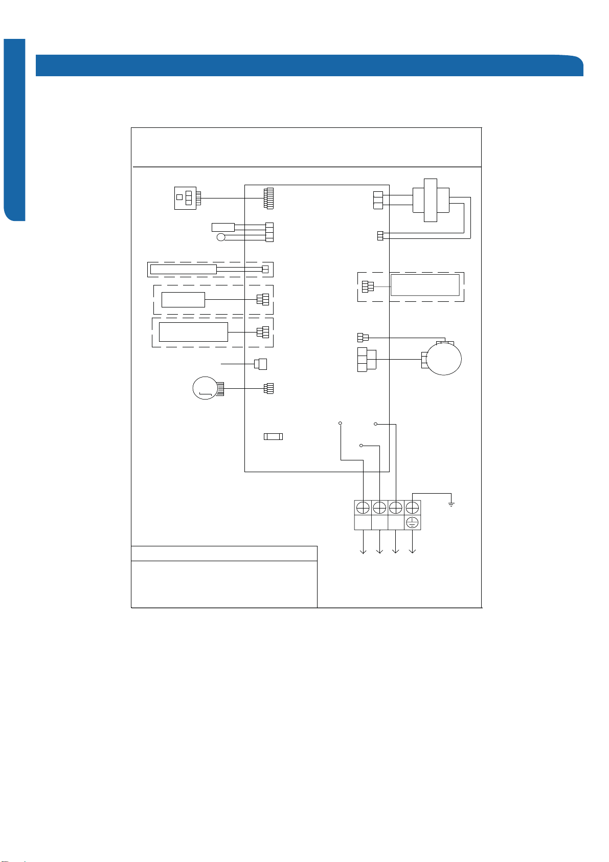
REFERENCE INFORMATION PAGE 61
Indoor Board Diagram
09K-12K
,1'225:5,1*',$*5$0
&1
0
83'2:167(3027250)86(7$9$&&172287'22581,7<*1RWHV7KHGRWWHGSDUWVDUHRSWLRQDO55HG::KLWH<<HOORZ<*<HOORZ*UHHQ%%ODFN%5%URZQ%/%OXH
$
&1/&1)$102725&1&1
:
,5('&21752//(5:,),5220&$5'&1&1&1$0%,(177(036(16253,3,1*7(036(1625',63/$<%2$5'&1&1%/%55
a
&1&1:5&175$16)250(5%/(0(5*(1&<6:,7&+&1&1
&(175$/
&21752//(5&1
0
83'2:167(3027250)86(7$9$&&172287'22581,7<*1RWHV7KHGRWWHGSDUWVDUHRSWLRQDO55HG::KLWH<<HOORZ<*<HOORZ*UHHQ%%ODFN%5%URZQ%/%OXH
$
&1/&1)$102725&1&1
:
,5('&21752//(5:,),5220&$5'&1&1&1$0%,(177(036(16253,3,1*7(036(1625',63/$<%2$5'&1&1%/%55
a
&1&1:5&175$16)250(5%/(0(5*(1&<6:,7&+&1&1
&(175$/
&21752//(5
ENGLISH
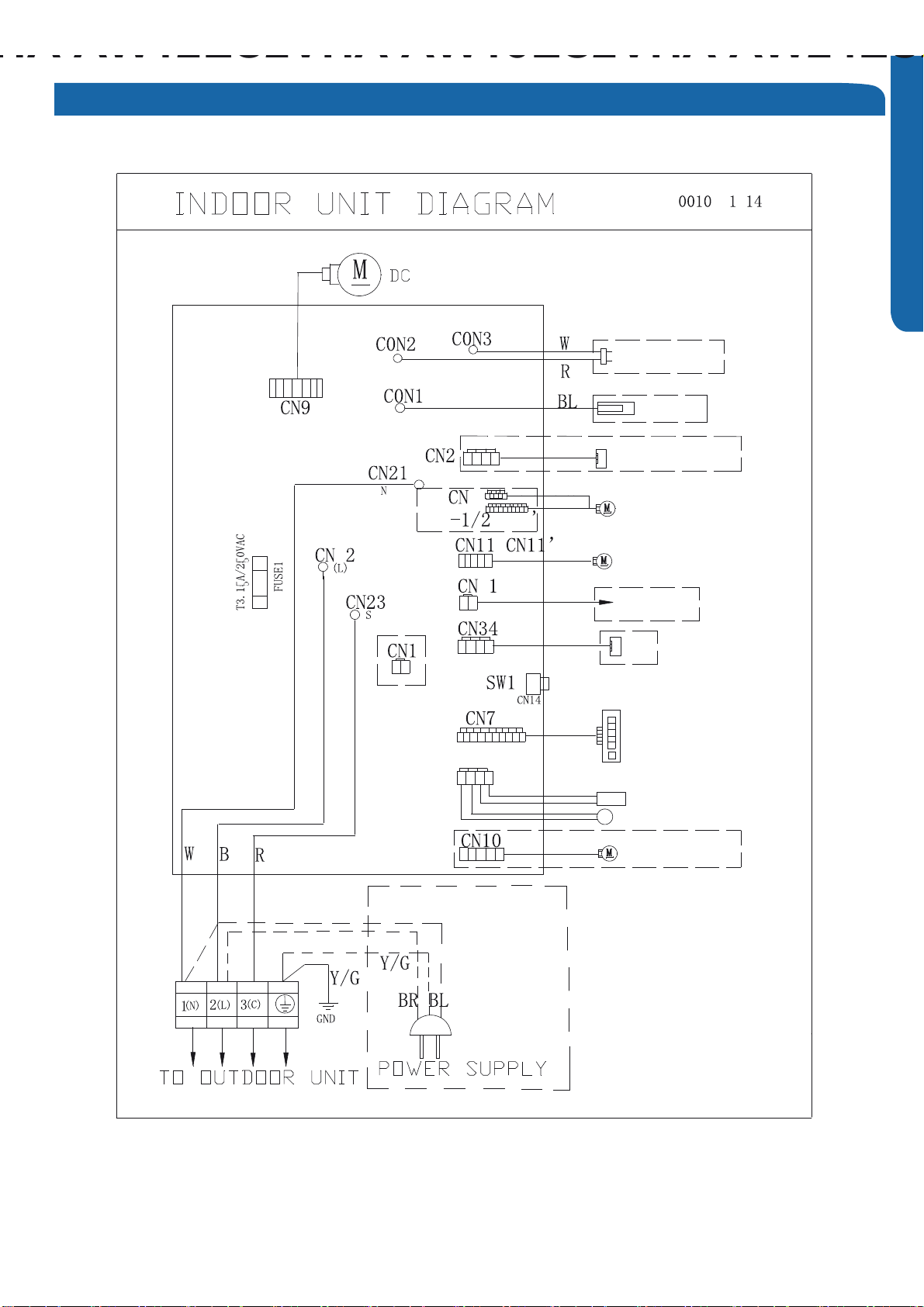
REFERENCE INFORMATION
PAGE 62
ENGLISH
Indoor Board Diagram
HA
AW12ES2VHA
AW18ES2VHA
AW24ES2
Up-down
stepmotor
Fan motor
EMERGENCY
SWITCH
RECEIVER DISPLAY
AMBIENT TEMP SENSOR
PIPING TEMP SENSOR
Right stepmotor
left stepmotor
Fresh air
Room card
@
WiFi @
@
W
ire controller
@
Ion generator
18-24K
CN5 CN5
5
5
5
CN6
56 5
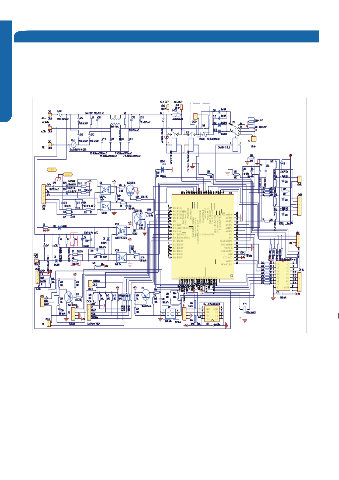
REFERENCE INFORMATION PAGE 63
ENGLISH
Indoor Board Schematic
09-12K
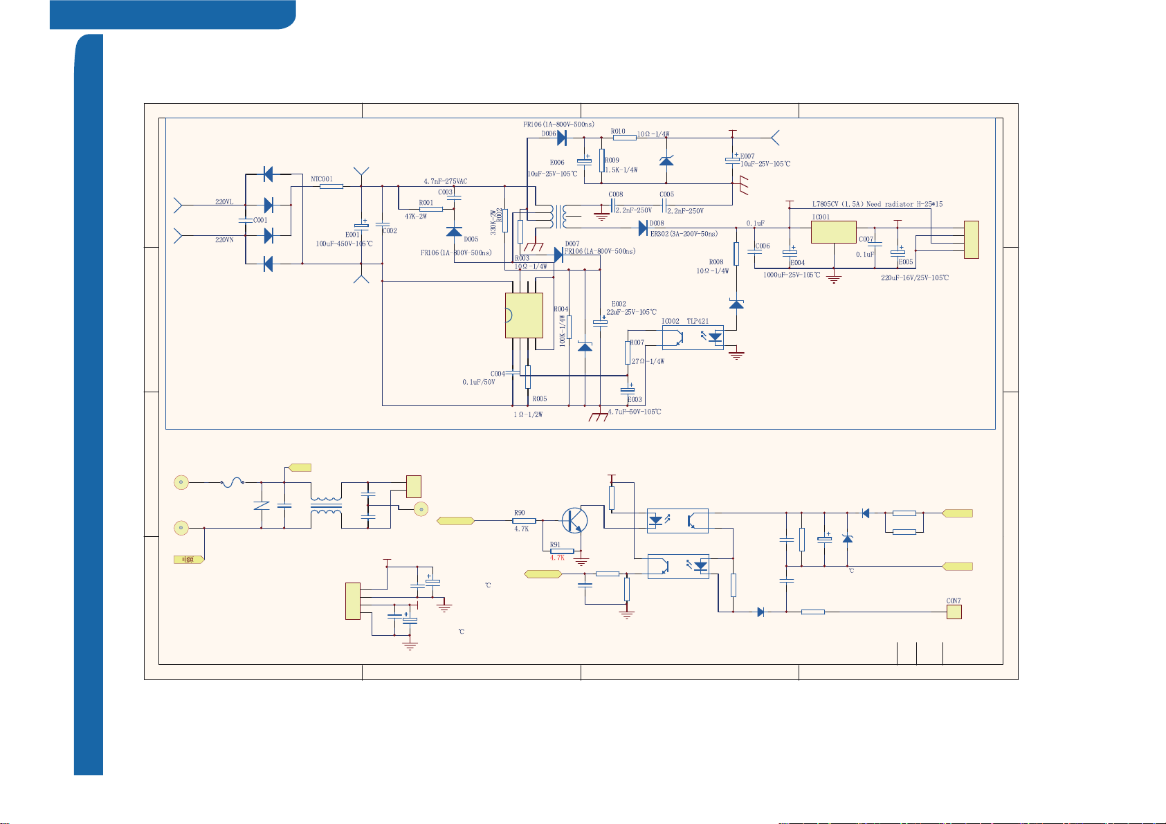
REFERENCE INFORMATION
PAGE 64
ENGLISH
Indoor Board Schematic
Domestic Heat Pump
9
1 2 43
A
B
C
D
4
321
D
C
B
A
C8
0.1uF-50V
A
1
K
2
C4
E3
IC4
TLP 85 1/ PC8 5 1
A1
K2
C
4
E
3
IC6
TLP4 2 1
R22
2K-1/4W
R26
2K-2W
R12
100K-1/4W
E4
100uF-50V-105
CY3
2.2nF-250VAC
220V_L
POWER_N
R14
47K-2W
R15
47K-2W
COMM
NEW FREEMATCH COM CIRCUI T
1
2
CN30
RTB-1.5-2P
220V_L
FUSE1
T3. 1 5A-25 0 VAC
1
CON1
1
124
3
243
LX1
LB22 7 1 (3 2mH-0 . 35 A)
Black
L
~ 22 0 VAC
CY1
2.2nF-250VAC
CY2
2 . 2n F- 25 0 VA C
1
CON13
1
CON2
RV1
TVR14 5 61 *
CX1
0.1uF-275VAC
1
N
1
2
3
4
CN002
80±5mm -Red /Black-4P
+5V
GND
+12V
GND
+5V
C17
0.1uF
E1
220uF-25V-105
+12V
C4
0.1uF
E6
220uF-25V-105
Whit e
Swi t ch p o wer sup pl y
A1
K2
C
4
E
3
+12V
Vin
1
GND
2
Vout 3
+5V
+15V
1
6
2
3
5
4
7
T00 1
BCK-6-FE1901H
D003 1N5399
D0 04 1 N53 9 9
D001 1N5399
D002 1N5399
0.1uF-275VAC
SCK084R72
ZD001
18V -1W
ZD002
1N4742A(12V-1W)
CON002
CON001
CON003
200±10mm -Black
CON004
200±10mm -Red
CON005
1
2
3
4
CN001
8 0± 5 mm -Re d /B la ck -4 P
ZD00 3
1N4746A(18V-1W)
220VAC~/50HZ
0.1uF-275VAC
+5V
+12V
GND
GND
This Switch power supply is designed for 12W
RED
BLACK
310V
1
1
2
2
3
3
4
455
66
77
88
IC0 0 3
ICE2 A26 5
VCC
R13
330
R20
1K R19
10K
C9
1nF
+5V
COMM_RX
C OMM_ TX
COMM_ TX
COMM_RX
N5
SS8050LT1H
D11
1N4007
ZD1
1N4746A(18V-1W)
D12
1N4007
K-K
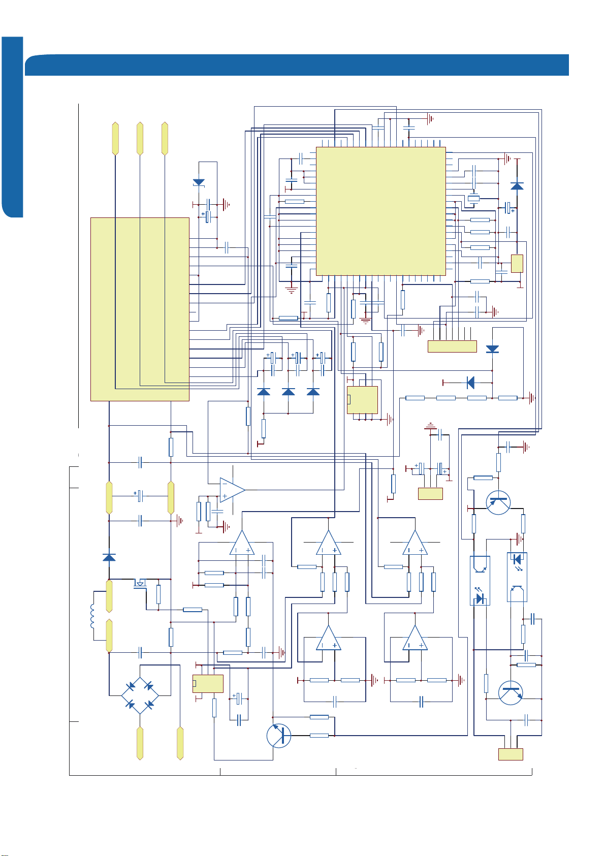
Outdoor Board Diagram
&1&1&1&1&1&1&1&1&15869&:
:5
028'/(3&%89:31&2035(6625%˖%/$&.<*˖<(//2:*5((1:˖:+,7(25˖25$1*(%/˖%/8(5˖5('
$&1287&1&1$&/287&1:$<9$/9(0&1&19$/9($&13(
32:(5
%/RU:<*
&1&20%&20$1
5
&1&1$&1$&/)86(7$9$&&1&102'8/(&2002'8/(32:(5
72,1'22581,7
&1%%/
%/25
&15($&725
%%
'&)$1
287'2253&%
(/(&75,&(;3$16,21
<*
<*
1/&
%/RU:%/
$&//,$&1/
&113&1
1/
::%5RU%
&$309$/9(02725127(67+('277('3$576$5(237,21$/#
and @2 cannot exist at
the same time but must
keep one of them.
287'22581,7:,5,1*',$*5$0&$3&$3
'217728&+&$3$&,725(9(1$)7(53/8*2))'$1*(52)(/(&75,&6+2&.
7KHFDSDFLWRUUHWDLQVKLJKYROWDJHHYHQDIWHUWKHSOXJRII)RU\RXUVDIHW\EHVXUHWRZDLWDWOHDVWPLQXWHVDIWHUSOXJRIIDQGXVHDWHVWHUWRFRQILUPWKHYROWDJHEHWZHHQFRQQHFWRU3DQG1LVOHVVWKDQ'&9EHIRUHVWDUWVHUYLFLQJ
&1&1$&1287$&/287
%5RU%
$$&*$;*$3,3,1*&1&17&
&2037(036(1625'()52677(036(1625
&6&1
$0%,(177(036(1625
+:&1
68&7,217(036(1625
4;&17(036(1625
%/RU:%/25:%525%
CN50 '5('OLQH
##
᳓ᤶᓴᓎ䲘㨷ᰧ㥝䛁҂䛁㗔ހ߬㘮⾥催ᑇ
4+5
ϡᑆ㛊ࠋક
52+6
W
287'225:,5,1*',$*5$0
%
䚼કৡ⿄ᔶᓣᡩᕅ⊩买㡆ܼ⹀࣪ሖ⏅㸼䴶໘⧚⛁໘⧚㸼䴶⹀ᑺᴤ᭭᮹ᳳᴤ᭭ሎᇌ
3(7
ᬍҎᬍ᭛ӊো䚼ક䗖⫼ޚ4+.7-↨՟䋼䞣J⊼݀Ꮒ䗖⫼ޚ
㒓䏃
$%6
ḋ䆄ᅵᅮޚ࣪᮹ᳳ݅ᓴᓴ⼎ҹџ乍ᣝ4+.7-䴦ቯ⍋ᇨぎ䇗఼᳝䰤ᘏ݀ৌ
%
8%8(5(8%8(5(
㸼䴶㉫㊭ᑺ˖⠜䆄໘᭄ㅒᄫᑩᘏোᅵḌᇍ䆒䅵Ꮉ㡎᮹ᳳ䆄
ᡔᴃ㽕∖˖ǃ买㡆ǃ⠜䴶䆒㕂ヺড়ޚ˗ǃ⠜䴶⏙᱄᮴∵⠽˗ǃࠋᄫԧ⏙᱄˗ǃ᠔᳝乍ЎᖙẔ乍˗ǃ᳝ᆇ⠽䋼ᑨヺড়ޚ
4+5
4+5
ⱘⳌ݇㽕∖DŽ
g
C009
471
1
2
3
4
5
6
7
8
9
10
11
12
13
14
15
16
17
18
19
20
21
22
23
24
25
26
27
28
29
30
31
32
33
34
35
36
37
38
39
40
41
42
43
44
45
46
47
48
49
50
51
52
53
54
55
56
57
58
59
60
61
62
63
64
65
66
67
68
69
70
71
72
73
74
75
76
77
78
79
80
IC1
SH70 46
IC8
SGH4 0N 60 UF
1
2
3
4
BG 1
D2 5BX6 0B
D207
FFA3 0U 60 DN
C4 0 4
474/630VDC
C405
104/275V
L
5.2MH/15A
AC-L
AC-N
LOLI
CN 8
CN 9
6NC7NC
RS1
0.015/5W
R215
10K RS 2
0.02/5W
R0 03 4. 7K
R0 01 4. 7K
R0 02 4. 7K
R0 04 4. 7K
R006 100
P
N
CN 1
CN 5
680U/400V*2
24
20
P
N
U
V
W
CN 2
CN 3
CN 4
234567891011121314151617
VUF B
VP
UN
VVF B
VW FB
WP
UP
VP1
VN1
WN
VNC
VN
FO
CIN
VNC
VNO
PS 2 19 64 -A T/ AS T/ PS 21 9 A4- ASTX
PM1
23
22
21
U
V
W
C008
47 4
C007
47 4
C013
104
C0 0 5
104
C030
471
C029
471
C201
104
X1 10M
R2 2 0 8 2
R2 19 1K
R2 1 8 8 2
R2 17 1K
R009 4.7K
R005 4.7K
R010
4.7K
R007 4.7K
1
2
3
4
5
6
7
CN 12
GN D
5V
MD 1
RX D
TXD
FWP
RE S
IC2
T600D
C202
104
C203
104
C207
104
C2 0 8
104
IC5
HA17 39 3A F
IC6
HA 16 30 D0 6
IC6
HA16 30 D0 6
R221 140
R216
10
R224
4.7K
R2 1 1
1K
R2 1 2
9.1K
R2 0 9 1 K
R223
330
R210 6.8K
R2 1 4
100
R2 0 7 1 K
5V
TR1
MMBT9 01 3
5V 15V
IC7
TLP2 51
2
35
6
8
4
8
5
6
7
R015
330
R208
6.8K
R014
330
R013
330
R018 4.7K
R016
1K
R012
4.7K
R011
4.7K
R0 0 8
4.7K
R0 1 9
4.7K
R213 100
1
2
3
4
5
6
7
8
IC4
HA 16 30 D0 6
IC4
HA16 30 D0 6
R2 0 6
1K
R2 0 5
1K
R2 0 3 1 K
R204 6.2K
R2 0 1 1 K
R202
6.2K
1
2
3
4
5
6
7
8
5V
5V
1
2
3
CN 11
䗮䆃
TR2
MMBT9 01 2
PC1
PC817A
PC2
PC817A
TR3
MMBT9 01 3
C018
103 C016
472
C017
223
C014
102
C0 3 6
104
C0 3 2
104
C023
224
C015
102
C0 3 4
104
C001
104
5V
C413
100U/25V
D2 03
US1M
D2 02
US1M
D2 01
US1M
C412
2 2U/ 2 5V
C411
2 2U/ 2 5V
C410
2 2U/ 2 5V
15V
5V
1
2
3
45
6
7
8
5V C004
104
C0 2 8
103
C0 2 0
102
5V
IC3
24C04
C205
223
C003
104
C002
104 C0 0 6
474
5V
R2 31 4. 7K
C0 2 2
103
R2 26 13 0KR2 27 13 0KR2 28 13 0KR2 29 4. 22 K
D205
LL 414 8
D2 04
LL 41 48
5V
1
2
3
CN 10
⬉⑤
(
㪱
)
15V
5V
C501
100U/16V C0 1 1
104
C5 0 2
100U/25V
C012
104
D206
2 4V/ 1 W
15V
R017 4.7K
D208
LL41 48
C503
4.7U/16V
5V
R2 3 0
10
5V
C406
104/275V
C504
100U/25V
IC5
HA 17 39 3A F
R222
330
R225 4.22K
C204 104
C019
103
1
23
5V
R2 22 , R2 25
খ᭄⬅㓽ᴎ䗔⺕⬉⌕䅵ㅫ㗠ᅮ
Module Board Schematic
ENGLISH
REFERENCE INFORMATION PAGE 65
REFERENCE INFORMATION
PAGE 66
ENGLISH
Ambient Sensor Tables
Temp°F Temp. °C M#\¢¥) ;\¢¥) #\¢¥) Tolerance (°C)
9-12K ;<=>?<@
-30.0 511.383 487.031 462.680 5.00 5.00
-29.0 478.574 456.022 433.470 4.95 4.95
-28.0 448.361 427.455 406.549 4.89 4.89
-27.0 420.230 400.844 381.458 4.84 4.84
-26.0 394.026 376.044 358.062 4.78 4.78
-25.0 369.606 352.922 336.238 4.73 4.73
-24.0 346.838 331.355 315.872 4.67 4.67
-23.0 325.602 311.229 296.856 4.62 4.62
-22.0 305.786 292.440 279.094 4.56 4.56
-21.0 287.287 274.892 262.497 4.51 4.51
-20.0 269.723 258.221 246.718 4.45 4.45
-19.0 253.871 243.171 232.471 4.40 4.40
-18.0 238.784 228.840 218.896 4.35 4.35
-17.0 224.677 215.433 206.189 4.29 4.29
-16.0 211.482 202.887 194.292 4.24 4.24
-15.0 199.133 191.140 183.147 4.18 4.18
-14.0 187.574 180.139 172.704 4.13 4.13
-13.0 176.749 169.832 162.915 4.07 4.07
-12.0 166.607 160.171 153.735 4.02 4.02
-11.0 157.103 151.113 145.123 3.96 3.96
-10.0 148.191 142.616 137.041 3.91 3.91
-9.0 139.834 134.644 129.454 3.85 3.85
-8.0 131.993 127.161 122.329 3.80 3.80
-7.0 124.634 120.134 115.634 3.75 3.75
-6.0 117.724 113.534 109.344 3.69 3.69
-5.0 111.235 107.332 103.429 3.64 3.64
-4.0 105.139 101.503 97.867 3.58 3.58
-3.0 99.408 96.021 92.634 3.53 3.53
-2.0 94.022 90.866 87.710 3.47 3.47
-1.0 88.955 86.015 83.075 3.42 3.42
0.0 84.220 81.479 78.739 3.36 3.36
1.0 79.704 77.151 74.598 3.31 3.31
2.0 75.481 73.102 70.723 3.25 3.25
ENGLISH
REFERENCE INFORMATION PAGE 67
ENGLISH
Rome Sensor Tables
Temp°F Temp. °C M#\¢¥) ;\¢¥) #\¢¥) Tolerance (°C)
3.0 71.505 69.288 67.071 3.20 3.20
4.0 67.759 65.693 63.627 3.15 3.15
5.0 64.230 62.304 60.378 3.09 3.09
6.0 60.903 59.108 57.313 3.04 3.04
7.0 57.767 56.094 54.421 2.98 2.98
8.0 54.808 53.249 51.690 2.93 2.93
9.0 52.017 50.564 49.111 2.87 2.87
10.0 49.383 48.029 46.675 2.82 2.82
11.0 46.896 45.635 44.374 2.76 2.76
12.0 44.548 43.373 42.198 2.71 2.71
13.0 42.331 41.236 40.141 2.65 2.65
14.0 40.235 39.215 38.195 2.60 2.60
15.0 38.254 37.304 36.354 2.55 2.55
16.0 36.381 35.497 34.613 2.49 2.49
17.0 34.611 33.788 32.965 2.44 2.44
18.0 32.935 32.169 31.403 2.38 2.38
19.0 31.351 30.638 29.925 2.33 2.33
20.0 29.850 29.187 28.524 2.27 2.27
21.0 28.430 27.813 27.196 2.22 2.22
22.0 27.086 26.512 25.938 2.16 2.16
23.0 25.811 25.278 24.745 2.11 2.11
24.0 24.604 24.109 23.614 2.05 2.05
25.0 23.460 23.000 22.540 2.00 2.00
26.0 22.397 21.948 21.499 2.04 2.04
27.0 21.387 20.950 20.513 2.09 2.09
28.0 20.429 20.003 19.577 2.13 2.13
29.0 19.521 19.105 18.689 2.18 2.18
30.0 18.656 18.251 17.846 2.22 2.22
31.0 17.835 17.440 17.045 2.26 2.26
32.0 17.054 16.670 16.286 2.31 2.31
33.0 16.313 15.938 15.563 2.35 2.35
34.0 15.608 15.243 14.878 2.39 2.39
35.0 14.936 14.581 14.226 2.44 2.44
36.0 14.299 13.953 13.607 2.48 2.48
37.0 13.691 13.354 13.017 2.53 2.53
38.0 13.113 12.785 12.457 2.57 2.57
ENGLISH
ENGLISH
Ambient Sensor Tables
REFERENCE INFORMATION
PAGE 68
ENGLISH
Temp°F Temp. °C M#\¢¥) ;\¢¥) #\¢¥) Tolerance (°C)
39.0 12.563 12.243 11.923 2.61 2.61
40.0 12.038 11.727 11.416 2.66 2.66
41.0 11.539 11.236 10.933 2.70 2.70
42.0 11.063 10.768 10.473 2.74 2.74
43.0 10.611 10.323 10.035 2.79 2.79
44.0 10.178 9.898 9.618 2.83 2.83
45.0 9.766 9.493 9.220 2.88 2.88
46.0 9.373 9.107 8.841 2.92 2.92
47.0 8.998 8.739 8.480 2.96 2.96
48.0 8.640 8.388 8.136 3.01 3.01
49.0 8.299 8.053 7.807 3.05 3.05
50.0 7.974 7.734 7.495 3.09 3.09
51.0 7.661 7.428 7.195 3.14 3.14
52.0 7.363 7.136 6.909 3.18 3.18
53.0 7.079 6.858 6.637 3.23 3.23
54.0 6.807 6.592 6.377 3.27 3.27
55.0 6.547 6.337 6.127 3.31 3.31
56.0 6.300 6.095 5.890 3.36 3.36
57.0 6.061 5.862 5.663 3.40 3.40
58.0 5.834 5.640 5.446 3.44 3.44
59.0 5.617 5.428 5.239 3.49 3.49
60.0 5.410 5.225 5.040 3.53 3.53
61.0 5.210 5.030 4.850 3.58 3.58
62.0 5.019 4.844 4.669 3.62 3.62
63.0 4.837 4.666 4.495 3.66 3.66
64.0 4.662 4.495 4.328 3.71 3.71
65.0 4.494 4.332 4.170 3.75 3.75
66.0 4.333 4.175 4.017 3.79 3.79
67.0 4.179 4.025 3.871 3.84 3.84
68.0 4.032 3.881 3.730 3.88 3.88
69.0 3.890 3.743 3.596 3.93 3.93
70.0 3.754 3.611 3.468 3.97 3.97
71.0 3.624 3.484 3.344 4.01 4.01
72.0 3.498 3.362 3.226 4.06 4.06
73.0 3.378 3.245 3.112 4.10 4.10
74.0 3.263 3.133 3.003 4.14 4.14
ENGLISH
Ambient Sensor Tables
REFERENCE INFORMATION PAGE 69
ENGLISH
Temp°F Temp. °C M#\¢¥) ;\¢¥) #\¢¥) Tolerance (°C)
75.0 3.153 3.026 2.899 4.19 4.19
76.0 3.046 2.922 2.798 4.23 4.23
77.0 2.944 2.823 2.702 4.28 4.28
78.0 2.845 2.727 2.609 4.32 4.32
79.0 2.751 2.636 2.521 4.36 4.36
80.0 2.659 2.547 2.435 4.41 4.41
81.0 2.573 2.463 2.353 4.45 4.45
82.0 2.488 2.381 2.274 4.49 4.49
83.0 2.407 2.303 2.199 4.54 4.54
84.0 2.329 2.227 2.125 4.58 4.58
85.0 2.253 2.154 2.054 4.63 4.63
86.0 2.182 2.085 1.988 4.67 4.67
87.0 2.112 2.017 1.922 4.71 4.71
88.0 2.046 1.953 1.860 4.76 4.76
89.0 1.981 1.890 1.799 4.80 4.80
90.0 1.919 1.830 1.741 4.84 4.84
91.0 1.859 1.772 1.685 4.89 4.89
92.0 1.801 1.716 1.631 4.93 4.93
93.0 1.745 1.662 1.579 4.98 4.98
94.0 1.691 1.610 1.529 5.02 5.02
95.0 1.639 1.560 1.481 5.06 5.06
96.0 1.589 1.512 1.435 5.11 5.11
97.0 1.540 1.465 1.390 5.15 5.15
98.0 1.494 1.420 1.346 5.19 5.19
99.0 1.449 1.377 1.305 5.24 5.24
100.0 1.406 1.335 1.264 5.28 5.28
101.0 1.363 1.294 1.225 5.33 5.33
102.0 1.322 1.255 1.188 5.37 5.37
103.0 1.283 1.217 1.151 5.41 5.41
104.0 1.244 1.180 1.116 5.46 5.46
105.0 1.208 1.145 1.082 5.50 5.50
ENGLISH
Ambient Sensor Tables
REFERENCE INFORMATION
PAGE 70
ENGLISH
Pipe Sensor Tables
#J* #J% #\¢¥_ ;\¢¥_ #\¢¥_ \J%_
-22 X^Z ]Y#G] ]# ]^G#^Y[ X]# ]#
XGZ#G XG ]# ]^#Y ]G#Z[ZY X]#^ ]#
X][# XG[ ]Y#YZ ]^]#ZGG ]][#G^ X]#] ]#^
X]Y#Y XG ]^[#]G[ ]G#^^G ]]]#[GY X]#[ ]#]
X]#[ -26 ]^Z#G^] ]]#^YY ]Z#[ X]#[ ]#
X]^ XG ]GG#[[ ]]Z#YG ]ZZ#]^Y X]#[ ]#Y
X]]#G XG ]]#GG ]Z#[[[G #[] X]#[^ ]#Y
X# XG^ ]Z#] #][[ [#[]ZY X]#[] ]#YY
X#Y -22 ]Z^#^[ ^#[^Z [#]Z^] X]#[ ]#Y
X#[ XG] #YY [[#[ [Z#YG[ X]#[ ]#Y^
X XGZ G#^ZG[ [#ZY Y#Z] X]#Y ]#YG
-2.2 X] [#G #YGGG G#G X]# ]#Y
XZ# X][ [G# #^[ Y[#[] X]#G ]#
]# X] [#]G^ ]#Z] Y#^[] X]# ]#
^#G X]Y ^#^ Y#^ YG#ZZ X]#Y[ ]#
X] Z#Z^G Y#^ZG^ [#[Y^ X]#YY ]#
Y#[ X] YY#^Y^ Y]#Z]G^ Y#ZY X]#Y ]#G
[#Y X]^ YG#[ #]] ^#GZ X]#YG ]#]
]Z# X]G #YZY #[YY Z#Y[] X]#Y ]#
]G#G X]] Y#GY G#GG[ [#GZ X]#[ ]#
] X]Z ^#YG #YG #[] X]#Y ]#Y
]#[ X Z#[Y #]YYY ^#Y] X]# ]#
]#Y X[ [#^][ #[ ]#[] X]#] ]#G
]# X #[[Y G#YG ^#Y]]G X]# ]#
G]#G -6 ^#]G Z#[ ^#G X]# ]#^
G^ X ]#G ^[#YGZ ^#^ X]# ]#^
G#[ X ^#^G ^Y#YY ^#G[^ X]#^ ]#^
26.6 X^ ^#Y ^#Z] ^G#]Z[ X]#] ]#^^
G[# -2 ^#YGZG ^^#^G ^]#GZYG X]#^[ ]#^]
^Z#G X] ^^#[^Y ^]#[ G#Y X]#^Y ]#G
^G Z ^G#GYZ[ ^Z#GY[ G[#GY X]#^ ]#G[
^^#[ ] ^Z#]YG G[#[[ G#]^] X]#^G ]#GY
^#Y 2 G#G G#] G#G X]#G ]#G
^# ^ G#[Z[ GY#G[[ G#Y[Y X]#G ]#GG
^#G GY#YZ G#Z[] G^#YZ X]#G ]#G
] G#^]^ G^#YG GG#YG^ X]#G^ ]#][
G#[ 6 G#]^G GG#[YY G]#Y^Y] X]#G ]#]Y
#Y G^#ZG[ G]#[^[ GZ#Y^ X]#][ ]#]
Y# [ G]#] GZ#[Y ]#[G X]#] ]#]G
[#G GZ#Y[[ ]#Z ][#Y^ X]#]^ ]#Z
Z ]Z GZ#Z]Y ]#ZYG] ][#]^[ X]#]] ]#Z
]#[ ]] ]#]] ][#GG ]#^YY X]#Z[ ]#Z
^#Y ]G ][#G[ ]#^^] ]Y#Y^Z X]#ZY ]#Z^
# ]^ ]#G ]Y#Y[G ]#^] X]#Z^ ]#Z]
#G ] ]Y#Y]] ]#YZ] ]#GY X]#Z] Z#
] ]#^YY ]#G ]#Y^] XZ#[ Z#Y
YZ#[ ]Y ]#G^[ ]#YGY[ ]#ZG] XZ#Y Z#18-254
18-24K JZZ[\]^=>?<@
ZZ[_];;[\<Z^^=?<@

REFERENCE INFORMATION PAGE 71
ENGLISH
Pipe Sensor Tables
#J* #J% #\¢¥_ ;\¢¥_ #\¢¥_ \J%_
62.6 ] ]#[ ]#ZZ ]^#] XZ#^ Z#G
Y# ][ ]^#^Y ]^#][ ]G#Z] XZ#] Z#
66.2 ] ]^#^^] ]G#[G ]G#^[ XZ#[[ Z#[
Y[ GZ ]G#][ ]G#^GG^ ]]#[[ XZ#[Y Z#[
Y#[ G] ]G#GG[ ]]#[]GY ]]#Z]] XZ#[^ Z#[^
]#Y 22 ]]#]ZG ]]#^GY ]Z# XZ#[] Z#[
^# G^ ]]#G]G ]Z#[Y^ ]Z#]] XZ#[ Z#[
#G G ]Z# ]Z#G]Y ]Z#ZY XZ# Z#
G ]Z#^ ]Z # XZ# Z#
[#[ 26 #[ # #G[ XZ#Y Z#Y
[Z#Y G #]G #G]^G [#][ XZ#[ Z#[
[G# G[ #] [#[Y [#Y XZ#[ Z#[^
[#G G [#G [#Y [#GZ]^ XZ#[ Z#[Y
[Y ^Z [#[^ [#]YG] #[Y] XZ#] Z#
[#[ ^] [#]^] #[G[ #GG XZ# Z#^
[#Y ^G #[G #^ #G[ XZ#[ Z#
]# ^^ #^ #GY] Y#Y]] X]#ZG ]
^#G ^ #GY Y#Y^ Y#Y[ X]#ZY ]#Z
^ Y#[G Y#ZZ[ Y#GGG X]#] ]#Z
Y#[ ^Y Y#G^ Y# Y#]Z X]#]^ ]#]]
[#Y ^ Y#[Z^ Y#GZG] #^Z X]#] ]#]
]ZZ# ^[ Y#G^ #Y[ #ZZ X]#G] ]#][
]ZG#G ^ Y#Z] # #[]G X]#G ]#GG
]Z Z # #^]Y #G]G X]#G ]#G
]Z#[ ] #] #^GY #ZZ X]#^^ ]#G
]Z#Y G #^]Y #]^Z[ #[[^ X]#^ ]#^^
]Z# ^ #GZZ] #^ #Y X]#] ]#^Y
]]]#G #Z]Y^ #Y^ #][ X]# ]#
]]^ #[ #Z #^ X]# ]#
]]#[ Y #YZ[ #GG #][[ X]#^ ]#
]]Y#Y #Z[^ #GYYY #Z^G X]# ]#]
]][# [ #^G #]] ^#[[YG X]#Y] ]#
]GZ#G #GZGY ^#Y[Y ^#^ X]#Y ]#
]GG Z #Z[[ ^#[G[ ^#YZ[ X]# ]#YG
]G^#[ ] ^#GZY ^#Y^ ^#[ X]# ]#YY
]G#Y G ^#[[ ^#Y ^#^^] X]#[ ]#
]G# ^ ^#YYZ] ^#]Y ^#G^^G X]#[G ]#
]G#G ^#^ ^#^GG ^#]][^ X]#[ ]#[
]^] ^#] ^#GZ[ ^#ZZ X]#] ]#[G
]^G#[ Y ^#^ZY ^#Z[ G#ZG] X]# ]#[
]^#Y ^#]Y G#^ G#[ZZ -2 ]#[
]^Y# [ ^#Z] G#[GG G#ZG XG#Z ]#^
]^[#G G#Z G#[ G#YZG XG#Z[ ]#
]Z YZ G#[^Y G#Z]G G#]^ XG#]^ G#Z]
]]#[ Y] G#[ G#Y]]G G#^G[ XG#] G#Z
]^#Y 62 G#Z G#GY G#^[ -2.22 G#Z
]# Y^ G#YG^G G#]^ G#G -2.26 G#]^
]#G Y G#^Y G#^Y]] G#]^G XG#^] G#]

REFERENCE INFORMATION
PAGE 72
ENGLISH
Pipe Sensor Tables
#J* #J% #\¢¥_ ;\¢¥_ #\¢¥_ \J%_
] Y G#] G#G[ G#]] XG#^Y G#G]
]Z#[ 66 G#^[] G#GZ[ G#Z[Y XG# G#G
]G#Y Y G#^ZY[ G#]^[^ ]#[Z^ XG# G#G
]# Y[ G#G^ G#ZY ]#] XG# G#^
]Y#G Y G#]YG G#ZZ^G ]#[]Y XG# G#^[
][ Z G#Z[^ ]#^^ ]#Z[ XG# G#G
]#[ ] G#Z^^ ]#[[ ]#^G XG#Y^ G#Y
]Y]#Y G ]#] ]#[][Y ]#YY] XG#Y[ G#
]Y^# ^ ]#]]^ ]#Y] ]#YG] XG#^ G#
]Y#G ]#[^^ ]#ZY ]#Y XG#[ G#[
]Y ]# ]#Y^^ ]#] XG#[^ G#Y^
]Y[#[ Y ]#^ ]#YZG] ]#] XG#[[ G#Y
]Z#Y ]#Y]^ ]#G[ ]#G^ XG#G G#]
]G# [ ]#YZ ]#Z] ]#^ XG# G#
]#G ]#G^ ]#G ]#^^Y X^#ZG G#[
]Y [Z ]# ]#] ]#GG X^#Z G#[
]#[ [] ]# ]#^G] ]#G X^#]G G#[[
]#Y [G ]#YG ]#^^Z[ ]#G]] X^#] G#^
][]# [^ ]#]^ ]#G] ]#]Y X^#GG G#
][^#G [ ]#^^ ]#GG ]#]] X^#G ^#Z]
][ [ ]#^^^ ]#G]^ ]#]ZYY X^#^G ^#ZY
][Y#[ [Y ]#G^ ]#] ]#Z^ X^#^[ ^#]
][[#Y [ ]#G[^ ]#][ ]#ZZ X^#^ ^#]
]Z# [[ ]#GGGY ]#]]]^ ]#ZZG X^#[ ^#]
]G#G [ ]#][[ ]#Z[ Z#[ X^#^ ^#G
] Z ]#]Y ]#ZY Z# X^#[ ^#G[
]#[ ] ]#]GG^ ]#Z] Z#G] X^#Y ^#^^
]#Y G ]#Z] Z#[[G Z#[G X^#Y ^#^
]# ^ ]#ZYZ Z# Z#[Y X^# ^#G
GZ]#G ]#Z^] Z#^GY Z#[G X^#[ ^#Y
GZ^ ]#ZZ^ Z#ZY] Z#[] X^#[ ^#]
GZ#[ Y Z#Y Z#[[ZY Z#] X^# ^#
GZY#Y Z# Z#[[ Z#]] X^#Y ^#Y
GZ[# [ Z#G^G Z#[^] Z#[ X#Z] ^#Y
G]Z#G Z#[[^ Z#[Z[[ Z#G X#Z ^#Y
G]G ]ZZ Z#[] Z#[Y^ Z#ZY X#]G ^#
G]^#[ ]Z] Z#[Z Z#YY Z#Y[Y X#][ ^#[
G]#Y ]ZG Z#[G[] Z#^Y Z#YYG X#G^ ^#[^
G]# ]Z^ Z#[ZY] Z#G^^ Z#Y[ X#G ^#[[
G]#G ]Z Z#[[ Z#Z^Y Z#Y^Z^ X#^ ^#G
GG] ]Z Z#Y] Z#Y[ Z#Y]G X# ^#
GGG#[ ]ZY Z#] Z#YYY] Z# X#Y #ZG
GG#Y ]Z Z#G Z#Y[G Z#G X#] #Z
GGY# ]Z[ Z#Z Z#Y^Z[ Z#Y^G X# #]G
GG[#G ]Z Z#Y[ Z#Y] Z#[ X#Y^ #]Y
G^Z ]]Z Z#Y Z# Z#^G[ X#Y #G]
G^]#[ ]]] Z#YG[ Z#[G Z#][^ X# #GY
G^^#Y ]]G Z#Y^Y] Z#YY Z#Z^ X#[ #^]
REFERENCE INFORMATION PAGE 73
ENGLISH
Ambient and Pipe Sensor Tables
Ambient, Defrost and Pipe Sensor Tables
235.4 113 0.62 0.5518 0.4907 -4.86 4.36
237.2 114 0.6043 0.5374 0.4775 -4.92 4.41
239 115 0.5891 0.5235 0.4648 -4.98 4.45
240.8 116 0.5743 0.51 0.4524 -5.04 4.5
242.6 117 0.56 0.4968 0.4404 -5.1 4.55
244.4 118 0.546 0.4841 0.4288 -5.16 4.6
246.2 119 0.5325 0.4717 0.4175 -5.22 4.65
248 120 0.5194 0.4597 0.4066 -5.28 4.7
-22 -30 165.2170 147.9497 132.3678 -1.94 1.75
-20 -29 155.5754 139.5600 125.0806 -1.93 1.74
-18 -28 146.5609 131.7022 118.2434 -1.91 1.73
-17 -27 138.1285 124.3392 111.8256 -1.89 1.71
-15 -26 130.2371 117.4366 105.7989 -1.87 1.70
-13 -25 122.8484 110.9627 100.1367 -1.85 1.69
-11 -24 115.9272 104.8882 94.8149 -1.83 1.67
-9 -23 109.4410 99.1858 89.8106 -1.81 1.66
-8 -22 103.3598 93.8305 85.1031 -1.80 1.64
-6 -21 97.6556 88.7989 80.6728 -1.78 1.63
-4 -20 92.3028 84.0695 76.5017 -1.76 1.62
-2 -19 87.2775 79.6222 72.5729 -1.74 1.60
0 -18 82.5577 75.4384 68.8710 -1.72 1.59
1 -17 78.1230 71.5010 65.3815 -1.70 1.57
3 -16 73.9543 67.7939 62.0907 -1.68 1.55
5 -15 70.0342 64.3023 58.9863 -1.66 1.54
7 -14 66.3463 61.0123 56.0565 -1.64 1.52
9 -13 62.8755 57.9110 53.2905 -1.62 1.51
10 -12 59.6076 54.9866 50.6781 -1.60 1.49
12 -11 56.5296 52.2278 48.2099 -1.58 1.47
14 -10 53.6294 49.6244 45.8771 -1.56 1.46
16 -9 50.8956 47.1666 43.6714 -1.54 1.44
18 -8 48.3178 44.8454 41.5851 -1.51 1.42
19 -7 45.8860 42.6525 39.6112 -1.49 1.40
21 -6 43.5912 40.5800 37.7429 -1.47 1.39
23 -5 41.4249 38.6207 35.9739 -1.45 1.37
25 -4 39.3792 36.7676 34.2983 -1.43 1.35
27 -3 37.4465 35.0144 32.7108 -1.41 1.33
28 -2 35.6202 33.3552 31.2062 -1.38 1.31
30 -1 33.8936 31.7844 29.7796 -1.36 1.29
32 0 32.2608 30.2968 28.4267 -1.34 1.28
34 1 30.7162 28.8875 27.1431 -1.32 1.26
36 2 29.2545 27.5519 25.9250 -1.29 1.24
37 3 27.8708 26.2858 24.7686 -1.27 1.22
39 4 26.5605 25.0851 23.6704 -1.25 1.20
41 5 25.3193 23.9462 22.6273 -1.23 1.18
43 6 24.1432 22.8656 21.6361 -1.20 1.16

REFERENCE INFORMATION
PAGE 74
ENGLISH
Ambient, Defrosting and Pipe Sensor Tables
Temp. °F Temp. °C M#\¢¥) ;\¢¥) #\¢¥) Tolerance (°C)
45 7 23.0284 21.8398 20.6939 -1.18 1.14
46 8 21.9714 20.8659 19.7982 -1.15 1.12
48 9 20.9688 19.9409 18.9463 -1.13 1.09
50 10 20.0176 19.0621 18.1358 -1.11 1.07
52 11 19.1149 18.2270 17.3646 -1.08 1.05
54 12 18.2580 17.4331 16.6305 -1.06 1.03
55 13 17.4442 16.6782 15.9315 -1.03 1.01
57 14 16.6711 15.9601 15.2657 -1.01 0.99
59 15 15.9366 15.2770 14.6315 -0.98 0.96
61 16 15.2385 14.6268 14.0271 -0.96 0.94
63 17 14.5748 14.0079 13.4510 -0.93 0.92
64 18 13.9436 13.4185 12.9017 -0.91 0.90
66 19 13.3431 12.8572 12.3778 -0.88 0.87
68 20 12.7718 12.3223 11.8780 -0.86 0.85
70 21 12.2280 11.8126 11.4011 -0.83 0.83
72 22 11.7102 11.3267 10.9459 -0.81 0.80
73 23 11.2172 10.8634 10.5114 -0.78 0.78
75 24 10.7475 10.4216 10.0964 -0.75 0.75
77 25 10.3000 10.0000 9.7000 -0.75 0.75
79 26 9.8975 9.5974 9.2980 -0.76 0.76
81 27 9.5129 9.2132 8.9148 -0.80 0.80
82 28 9.1454 8.8465 8.5496 -0.84 0.83
84 29 8.7942 8.4964 8.2013 -0.87 0.86
86 30 8.4583 8.1621 7.8691 -0.91 0.90
88 31 8.1371 7.8428 7.5522 -0.95 0.93
90 32 7.8299 7.5377 7.2498 -0.98 0.97
91 33 7.5359 7.2461 6.9611 -1.02 1.00
93 34 7.2546 6.9673 6.6854 -1.06 1.04
95 35 6.9852 6.7008 6.4222 -1.10 1.07
97 36 6.7273 6.4459 6.1707 -1.13 1.11
99 37 6.4803 6.2021 5.9304 -1.17 1.14
100 38 6.2437 5.9687 5.7007 -1.21 1.18
102 39 6.0170 5.7454 5.4812 -1.25 1.22
104 40 5.7997 5.5316 5.2712 -1.29 1.25
106 41 5.5914 5.3269 5.0704 -1.33 1.29
108 42 5.3916 5.1308 4.8783 -1.37 1.33
109 43 5.2001 4.9430 4.6944 -1.41 1.36
111 44 5.0163 4.7630 4.5185 -1.45 1.40
113 45 4.8400 4.5905 4.3500 -1.49 1.44
115 46 4.6708 4.4252 4.1887 -1.53 1.47
117 47 4.5083 4.2666 4.0342 -1.57 1.51
118 48 4.3524 4.1145 3.8862 -1.61 1.55
120 49 4.2026 3.9686 3.7443 -1.65 1.59
122 50 4.0588 3.8287 3.6084 -1.70 1.62
124 51 3.9206 3.6943 3.4780 -1.74 1.66
126 52 3.7878 3.5654 3.3531 -1.78 1.70
127 53 3.6601 3.4416 3.2332 -1.82 1.74
129 54 3.5374 3.3227 3.1183 -1.87 1.78
REFERENCE INFORMATION PAGE 75
ENGLISH
Ambient, Defrosting and Pipe Sensor Tables
Temp. °F Temp. °C M#\¢¥) ;\¢¥) #\¢¥) Tolerance (°C)
131 55 3.4195 3.2085 3.0079 -1.91 1.82
133 56 3.3060 3.0989 2.9021 -1.95 1.85
135 57 3.1969 2.9935 2.8005 -2.00 1.89
136 58 3.0919 2.8922 2.7029 -2.04 1.93
138 59 2.9909 2.7948 2.6092 -2.08 1.97
140 60 2.8936 2.7012 2.5193 -2.13 2.01
142 61 2.8000 2.6112 2.4328 -2.17 2.05
144 62 2.7099 2.5246 2.3498 -2.22 2.09
145 63 2.6232 2.4413 2.2700 -2.26 2.13
147 64 2.5396 2.3611 2.1932 -2.31 2.17
149 65 2.4591 2.2840 2.1195 -2.36 2.21
151 66 2.3815 2.2098 2.0486 -2.40 2.25
153 67 2.3068 2.1383 1.9803 -2.45 2.29
154 68 2.2347 2.0695 1.9147 -2.49 2.34
156 69 2.1652 2.0032 1.8516 -2.54 2.38
158 70 2.0983 1.9393 1.7908 -2.59 2.42
160 71 2.0337 1.8778 1.7324 -2.63 2.46
162 72 1.9714 1.8186 1.6761 -2.68 2.50
163 73 1.9113 1.7614 1.6219 -2.73 2.54
165 74 1.8533 1.7064 1.5697 -2.78 2.58
167 75 1.7974 1.6533 1.5194 -2.83 2.63
169 76 1.7434 1.6021 1.4710 -2.88 2.67
171 77 1.6913 1.5528 1.4243 -2.92 2.71
172 78 1.6409 1.5051 1.3794 -2.97 2.75
174 79 1.5923 1.4592 1.3360 -3.02 2.80
176 80 1.5454 1.4149 1.2942 -3.07 2.84
178 81 1.5000 1.3721 1.2540 -3.12 2.88
180 82 1.4562 1.3308 1.2151 -3.17 2.93
181 83 1.4139 1.2910 1.1776 -3.22 2.97
183 84 1.3730 1.2525 1.1415 -3.27 3.01
185 85 1.3335 1.2153 1.1066 -3.32 3.06
187 86 1.2953 1.1794 1.0730 -3.38 3.10
189 87 1.2583 1.1448 1.0405 -3.43 3.15
190 88 1.2226 1.1113 1.0092 -3.48 3.19
192 89 1.1880 1.0789 0.9789 -3.53 3.24
194 90 1.1546 1.0476 0.9497 -3.58 3.28
196 91 1.1223 1.0174 0.9215 -3.64 3.33
198 92 1.0910 0.9882 0.8942 -3.69 3.37
199 93 1.0607 0.9599 0.8679 -3.74 3.42
201 94 1.0314 0.9326 0.8424 -3.80 3.46
203 95 1.0030 0.9061 0.8179 -3.85 3.51
205 96 0.9756 0.8806 0.7941 -3.90 3.55
207 97 0.9490 0.8558 0.7711 -3.96 3.60
208 98 0.9232 0.8319 0.7489 -4.01 3.64
210 99 0.8983 0.8088 0.7275 -4.07 3.69
212 100 0.8741 0.7863 0.7067 -4.12 3.74
214 101 0.8507 0.7646 0.6867 -4.18 3.78
216 102 0.8281 0.7436 0.6672 -4.23 3.83
REFERENCE INFORMATION
PAGE 76
ENGLISH
Discharge Sensor Tables
Ambient, Defrosting and Pipe Sensor Tables
Temp. °F Temp. °C M#\¢¥) ;\¢¥) #\¢¥) Tolerance (°C)
217 103 0.8061 0.7233 0.6484 -4.29 3.88
219 104 0.7848 0.7036 0.6303 -4.34 3.92
221 105 0.7641 0.6845 0.6127 -4.40 3.97
223 106 0.7441 0.6661 0.5957 -4.46 4.02
225 107 0.7247 0.6482 0.5792 -4.51 4.07
226 108 0.7059 0.6308 0.5632 -4.57 4.12
228 109 0.6877 0.6140 0.5478 -4.63 4.16
230 110 0.6700 0.5977 0.5328 -4.69 4.21
232 111 0.6528 0.5820 0.5183 -4.74 4.26
234 112 0.6361 0.5667 0.5043 -4.80 4.31
235 113 0.6200 0.5518 0.4907 -4.86 4.36
237 114 0.6043 0.5374 0.4775 -4.92 4.41
239 115 0.5891 0.5235 0.4648 -4.98 4.45
241 116 0.5743 0.5100 0.4524 -5.04 4.50
243 117 0.5600 0.4968 0.4404 -5.10 4.55
244 118 0.5460 0.4841 0.4288 -5.16 4.60
246 119 0.5325 0.4717 0.4175 -5.22 4.65
248 120 0.5194 0.4597 0.4066 -5.28 4.70
Temp.(°F) Temp.(°C) M#\¢¥) ;\¢¥) #\¢¥) Tolerance
-22 -30 14646.0505 12061.7438 9924.4999 -2.96 2.45
-20.2 -29 13654.1707 11267.873 9290.2526 -2.95 2.44
-18.4 -28 12735.8378 10531.3695 8700.6388 -2.93 2.44
-16.6 -27 11885.1336 9847.724 8152.2338 -2.92 2.43
-14.8 -26 11096.6531 9212.8101 7641.8972 -2.91 2.42
-13 -25 10365.4565 8622.8491 7166.7474 -2.9 2.42
-11.2 -24 9687.027 8074.3787 6724.1389 -2.88 2.41
-9.4 -23 9057.2314 7564.2244 6311.6413 -2.87 2.41
-7.6 -22 8472.2852 7089.4741 5927.0206 -2.86 2.4
-5.8 -21 7928.7217 6647.4547 5568.2222 -2.84 2.39
-4 -20 7423.3626 6235.7109 5233.3554 -2.83 2.39
-2.2 -19 6953.293 5851.9864 4920.6791 -2.82 2.38
-0.4 -18 6515.8375 5494.2064 4628.5894 -2.8 2.37
1.4 -17 6108.5393 5160.4621 4355.6078 -2.79 2.37
3.2 -16 5729.1413 4848.9963 4100.3708 -2.77 2.36
5 -15 5375.5683 4558.1906 3861.6201 -2.76 2.35
6.8 -14 5045.9114 4286.5535 3638.1938 -2.75 2.34
8.6 -13 4738.4141 4032.7098 3429.0191 -2.73 2.34
10.4 -12 4451.4586 3795.391 3233.1039 -2.72 2.33
12.2 -11 4183.5548 3573.426 3049.5312 -2.7 2.32
14 -10 3933.3289 3365.7336 2877.4527 -2.69 2.31
15.8 -9 3699.5139 3171.3148 2716.0828 -2.67 2.3
17.6 -8 3480.9407 2989.246 2564.6945 -2.66 2.29
19.4 -7 3276.5302 2818.6731 2422.6139 -2.64 2.28
21.2 -6 3085.2854 2658.8058 2289.2164 -2.63 2.28
23 -5 2906.2851 2508.9126 2163.923 -2.61 2.27
J]Z`[\^=>?<@
ZZ[_]Z`[\{{^=?<@
REFERENCE INFORMATION PAGE 77
ENGLISH
Discharge Sensor Tables
Temp.(°F) Temp.(°C) M#\¢¥) ;\¢¥) #\¢¥) Tolerance
24.8 -4 2738.6777 2368.3158 2046.1961 -2.6 2.26
26.6 -3 2581.6752 2236.3876 1935.5371 -2.58 2.25
28.4 -2 2434.5487 2112.5459 1831.4826 -2.56 2.24
30.2 -1 2296.623 1996.2509 1733.6024 -2.55 2.23
32 0 2167.273 1887.0018 1641.4966 -2.53 2.22
33.8 1 2045.9191 1784.3336 1554.7931 -2.52 2.21
35.6 2 1932.0242 1687.8144 1473.146 -2.5 2.2
37.4 3 1825.0899 1597.0431 1396.2333 -2.48 2.19
39.2 4 1724.654 1511.6468 1323.7551 -2.47 2.17
41 5 1630.287 1431.2787 1255.4324 -2.45 2.16
42.8 6 1541.5904 1355.6163 1191.0048 -2.43 2.15
44.6 7 1458.1938 1284.3593 1130.2298 -2.41 2.14
46.4 8 1379.7528 1217.2282 1072.8813 -2.4 2.13
48.2 9 1305.9472 1153.9626 1018.7481 -2.38 2.12
50 10 1236.4792 1094.32 967.6334 -2.36 2.11
51.8 11 1171.0715 1038.0743 919.3533 -2.35 2.09
53.6 12 1109.4661 985.0146 873.7359 -2.33 2.08
55.4 13 1051.4226 934.944 830.621 -2.31 2.07
57.2 14 996.7169 887.6792 789.8583 -2.29 2.06
59 15 945.1404 843.0486 751.3077 -2.27 2.04
60.8 16 896.4981 800.8922 714.838 -2.26 2.03
62.6 17 850.6086 761.0603 680.3265 -2.24 2.02
64.4 18 807.3024 723.4134 647.658 -2.22 2
66.2 19 766.4212 687.8205 616.7252 -2.2 1.99
68 20 727.8172 654.1596 587.4271 -2.18 1.98
69.8 21 691.3524 622.3161 559.6694 -2.16 1.96
71.6 22 656.8979 592.1831 533.3634 -2.14 1.95
73.4 23 624.3328 563.6604 508.4261 -2.12 1.93
75.2 24 593.5446 536.654 484.7796 -2.1 1.92
77 25 564.4275 511.076 462.351 -2.09 1.9
78.8 26 536.9865 486.9352 441.1516 -2.07 1.89
80.6 27 511.0105 464.05 421.0258 -2.05 1.87
82.4 28 486.4151 442.3499 401.9146 -2.03 1.86
84.2 29 463.1208 421.7683 383.7626 -2.01 1.84
86 30 441.0535 402.243 366.5175 -1.99 1.83
87.8 31 420.1431 383.7151 350.1301 -1.97 1.81
89.6 32 400.3242 366.1295 334.5542 -1.95 1.8
91.4 33 381.535 349.4341 319.746 -1.93 1.78
93.2 34 363.7176 333.5801 305.6645 -1.9 1.76
95 35 346.8176 318.5216 292.2709 -1.88 1.75
96.8 36 330.7839 304.2151 279.5286 -1.86 1.73
98.6 37 315.5682 290.6199 267.4031 -1.84 1.71
100.4 38 301.1254 277.6976 255.862 -1.82 1.7
102.2 39 287.4128 265.4119 244.8745 -1.8 1.68
104 40 274.3905 253.7288 234.4118 -1.78 1.66
105.8 41 262.0206 242.6161 224.4465 -1.76 1.64
107.6 42 250.2676 232.0436 214.9529 -1.74 1.63
109.4 43 239.0983 221.9825 205.9065 -1.71 1.61
111.2 44 228.4809 212.406 197.2844 -1.69 1.59

REFERENCE INFORMATION
PAGE 78
ENGLISH
Discharge Sensor Tables
Temp.(°F) Temp.(°C) M#\¢¥) ;\¢¥) #\¢¥) Tolerance
113 45 218.386 203.2887 189.0648 -1.67 1.57
114.8 46 208.7855 194.6066 181.2273 -1.65 1.55
116.6 47 199.6531 186.3369 173.7524 -1.63 1.54
118.4 48 190.9639 178.4584 166.6217 -1.6 1.52
120.2 49 182.6945 170.9508 159.8181 -1.58 1.5
122 50 174.8228 163.7951 153.3249 -1.56 1.48
123.8 51 167.328 156.9733 147.1268 -1.53 1.46
125.6 52 160.1904 150.4683 141.209 -1.51 1.44
127.4 53 153.3914 144.2641 135.5577 -1.49 1.42
129.2 54 146.9136 138.3454 130.1598 -1.47 1.4
131 55 140.7403 132.698 125.0027 -1.44 1.38
132.8 56 134.8559 127.3081 120.0746 -1.42 1.36
134.6 57 129.2457 122.163 115.3645 -1.4 1.34
136.4 58 123.8956 117.2504 110.8618 -1.37 1.32
138.2 59 118.7926 112.5589 106.5564 -1.35 1.3
140 60 113.9241 108.0776 102.4388 -1.32 1.28
141.8 61 109.2784 103.7961 98.5 -1.3 1.26
143.6 62 104.8443 99.7046 94.7315 -1.28 1.23
145.4 63 100.6112 95.7939 91.1253 -1.25 1.21
147.2 64 96.5692 92.0553 87.6735 -1.23 1.19
149 65 92.7088 88.4805 84.369 -1.2 1.17
150.8 66 89.0211 85.0614 81.2048 -1.18 1.15
152.6 67 85.4976 81.7908 78.1744 -1.15 1.12
154.4 68 82.1303 78.6615 75.2715 -1.13 1.1
156.2 69 78.9116 75.6668 72.4902 -1.1 1.08
158 70 75.8343 72.8004 69.8249 -1.08 1.06
159.8 71 72.8916 70.0561 67.2703 -1.05 1.03
161.6 72 70.077 67.4283 64.8213 -1.03 1.01
163.4 73 67.3844 64.9115 62.4731 -1 0.99
165.2 74 64.808 62.5006 60.2211 -0.98 0.96
167 75 62.3423 60.1906 58.0609 -0.95 0.94
168.8 76 59.9821 57.977 55.9885 -0.92 0.92
170.6 77 57.7223 55.8552 53.9998 -0.9 0.89
172.4 78 55.5583 53.821 52.0912 -0.87 0.87
174.2 79 53.4856 51.8706 50.2591 -0.85 0.84
176 80 51.5 50 48.5 -0.85 0.84
177.8 81 49.7063 48.2057 46.7083 -0.85 0.85
179.6 82 47.9835 46.4842 44.9911 -0.89 0.89
181.4 83 46.3286 44.8323 43.3452 -0.93 0.92
183.2 84 44.7385 43.2468 41.7672 -0.96 0.95
185 85 43.2105 41.7248 40.254 -1 0.99
186.8 86 41.7386 40.2604 38.7996 -1.03 1.02
188.6 87 40.3241 38.8545 37.4048 -1.07 1.06
190.4 88 38.9643 37.5045 36.0668 -1.11 1.09
192.2 89 37.6569 36.2078 34.7831 -1.14 1.13
194 90 36.3996 34.9622 33.5513 -1.18 1.16
195.8 91 35.1903 33.7653 32.3689 -1.22 1.19
197.6 92 34.0269 32.6151 31.2338 -1.26 1.23
199.4 93 32.9075 31.5096 30.1438 -1.3 1.27
REFERENCE INFORMATION PAGE 79
ENGLISH
Discharge Sensor Tables
Temp.(°F) Temp.(°C) M#\¢¥) ;\¢¥) #\¢¥) Tolerance
201.2 94 31.8302 30.4467 29.097 -1.33 1.3
203 95 30.7933 29.4246 28.0915 -1.37 1.34
204.8 96 29.795 28.4417 27.1254 -1.41 1.37
206.6 97 28.8337 27.4961 26.197 -1.45 1.41
208.4 98 27.9078 26.5864 25.3048 -1.49 1.44
210.2 99 27.016 25.711 24.447 -1.53 1.48
212 100 26.1569 24.8685 23.6222 -1.57 1.52
213.8 101 25.329 24.0574 22.8291 -1.61 1.55
215.6 102 24.5311 23.2765 22.0662 -1.65 1.59
217.4 103 23.762 22.5245 21.3323 -1.69 1.63
219.2 104 23.0205 21.8002 20.6261 -1.73 1.66
221 105 22.3055 21.1025 19.9465 -1.77 1.7
222.8 106 21.6159 20.4303 19.2924 -1.81 1.74
224.6 107 20.9508 19.7825 18.6626 -1.85 1.77
226.4 108 20.3091 19.1582 18.0563 -1.89 1.81
228.2 109 19.6899 18.5564 17.4723 -1.93 1.85
230 110 19.0924 17.9761 16.9098 -1.98 1.89
231.8 111 18.5157 17.4166 16.368 -2.02 1.93
233.6 112 17.959 16.8769 15.8458 -2.06 1.96
235.4 113 17.4214 16.3564 15.3427 -2.1 2
237.2 114 16.9023 15.8542 14.8577 -2.15 2.04
239 115 16.401 15.3696 14.3902 -2.19 2.08
240.8 116 15.9167 14.902 13.9394 -2.23 2.12
242.6 117 15.4489 14.4506 13.5047 -2.27 2.16
244.4 118 14.9968 14.0149 13.0855 -2.32 2.19
246.2 119 14.5599 13.5942 12.6811 -2.36 2.23
248 120 14.1376 13.1879 12.2909 -2.41 2.27
249.8 121 13.7294 12.7955 11.9144 -2.45 2.31
251.6 122 13.3347 12.4165 11.551 -2.5 2.35
253.4 123 12.9531 12.0503 11.2003 -2.54 2.39
255.2 124 12.584 11.6965 10.8617 -2.58 2.43
257 125 12.227 11.3545 10.5348 -2.63 2.47
258.8 126 11.8817 11.024 10.2191 -2.68 2.51
260.6 127 11.5475 10.7046 9.9142 -2.72 2.55
262.4 128 11.2242 10.3957 9.6197 -2.77 2.59
264.2 129 10.9112 10.097 9.3352 -2.81 2.63
266 130 10.6084 9.8082 9.0602 -2.86 2.67
267.8 131 10.3151 9.5288 8.7945 -2.91 2.71
269.6 132 10.0312 9.2586 8.5378 -2.95 2.75
271.4 133 9.7563 8.9971 8.2895 -3 2.8
273.2 134 9.4901 8.7441 8.0495 -3.05 2.84
275 135 9.2322 8.4993 7.8175 -3.09 2.88
276.8 136 8.9824 8.2623 7.5931 -3.14 2.92
278.6 137 8.7404 8.0329 7.376 -3.19 2.96
280.4 138 8.5059 7.8108 7.166 -3.24 3
282.2 139 8.2787 7.5958 6.9629 -3.29 3.04
284 140 8.0584 7.3875 6.7664 -3.33 3.09

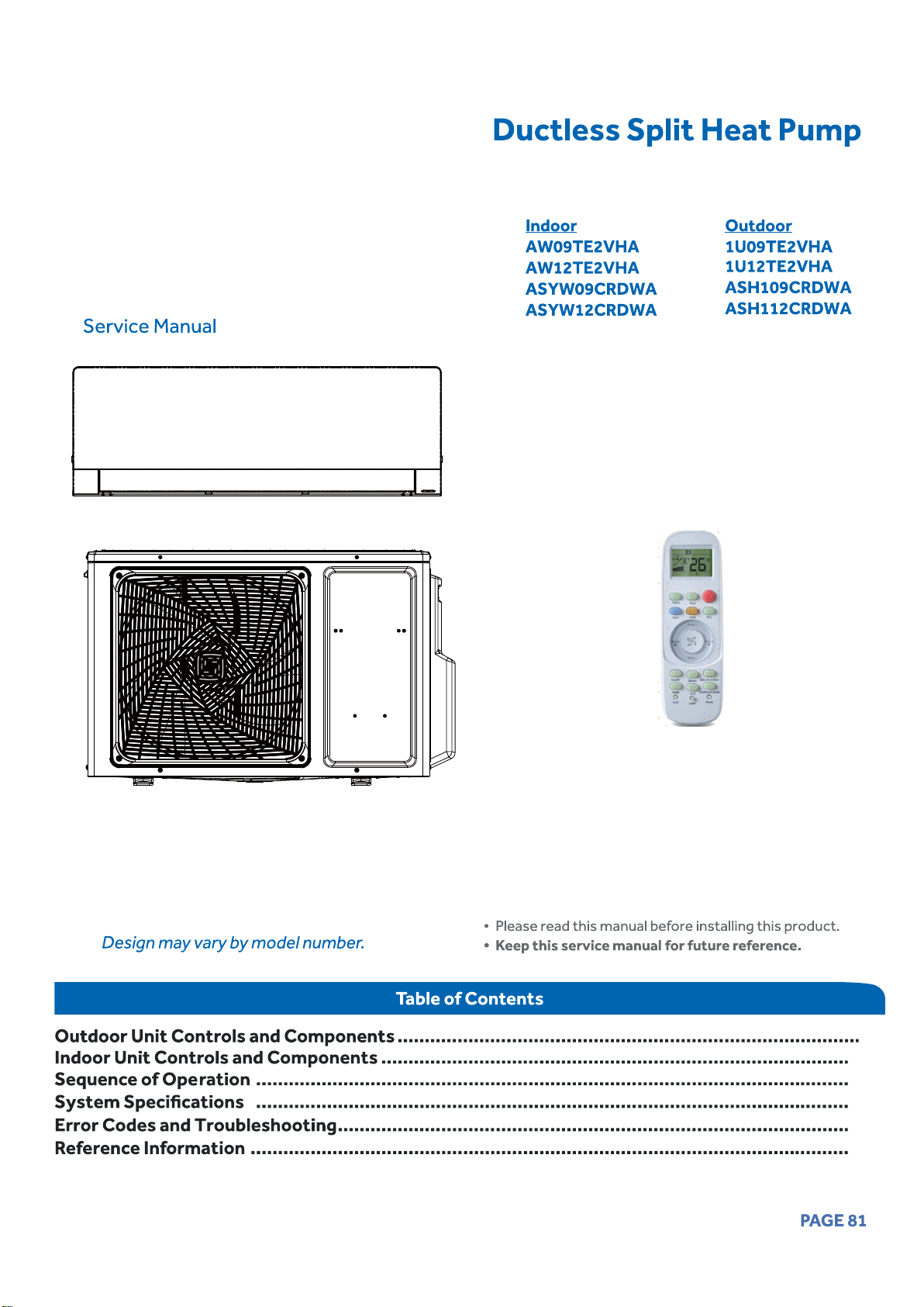
83
89
95
103
104
133
New Models:

[This page intentionally left blank.]
Outdoor Unit Controls and Components
Table of Contents
Outdoor Unit Introduction ............................................................................................................................................... 84
84
Outdoor Main Control Board .......................................................................................................................................... . 85
Terminal Block ................................................................................................................................................................. . 86
Reactor ............................................................................................................................................................................ 86
Compressor ................................................................................................................................................................. ... . 86
Outdoor Fan Motor ........................................................................................................................................................... 86
Discharge Temperature Sensor ..................................................................................................................................... . 87
Defrost Temperature Sensor ............................................................................................................................................ 87
Outdoor Ambient Temperature Sensor .......................................................................................................................... 87
Suction Line Temperature Sensor ....................................................................................................................................87
4-Way Valve ..................................................................................................................................................................... 88
Electronic Expansion Valve ..............................................................................................................................................88
Accumulato
r ................................................................................................... ................................................................. 88
........................... .... ................ 88
Strainers ................................................................... .. .........
................................................................................................................................ .
........................................ .
.. ......
83PAGE
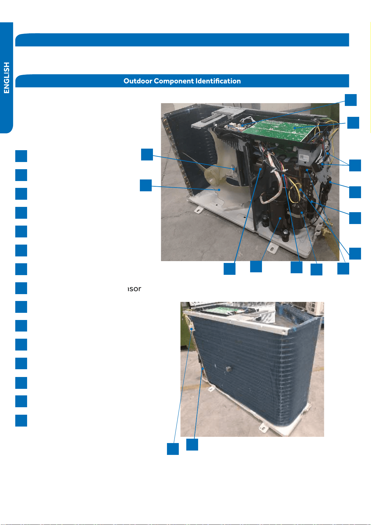
84 OUTDOOR UNIT CONTROLS and COMPONENTS
Outdoor Unit Introduction
T
he
outdoor
unit
has
t
w
o
circuit
board
s
,
an Inverter P
o
w
er Module (IPM) that
drives
the
c
ompressor and main control
board (PCB)
that
manages
system
●
functions
and
i
n
verter
calculation
s
.
Sensor
s
moni
t
or
k
e
y
tempe
r
a
t
ures
th
r
oughout
the
s
y
stem
t
o
manage
ope
r
ational
decision
s
.
4-
W
a
y
V
alve
Accumulator
C
ompressor
Def
r
ost
Tempe
r
at
ure
Sensor
Discharge
Tempe
r
at
ure
Sensor
Elect
r
onic
Expansion
V
alve
Refrige
r
ant
Strainers
Ambient
Tempe
r
at
ure
Sensor
F
an
M
o
t
or
P
o
wer
F
ac
t
or
Reac
t
or
S
uction
Line
Tempe
r
at
ure
Sensor
Terminal
Block
M
ain
C
ont
r
ol
Board (PCB)
M
odule
C
ont
r
ol
Board (IPM)
F
an
Blade
1
2
3
4
5
6
7
8
9
10
11
12
13
14
15
4
●
6
11
12
13
14
1
3
7
9
10
15
2
8
5
PAGE
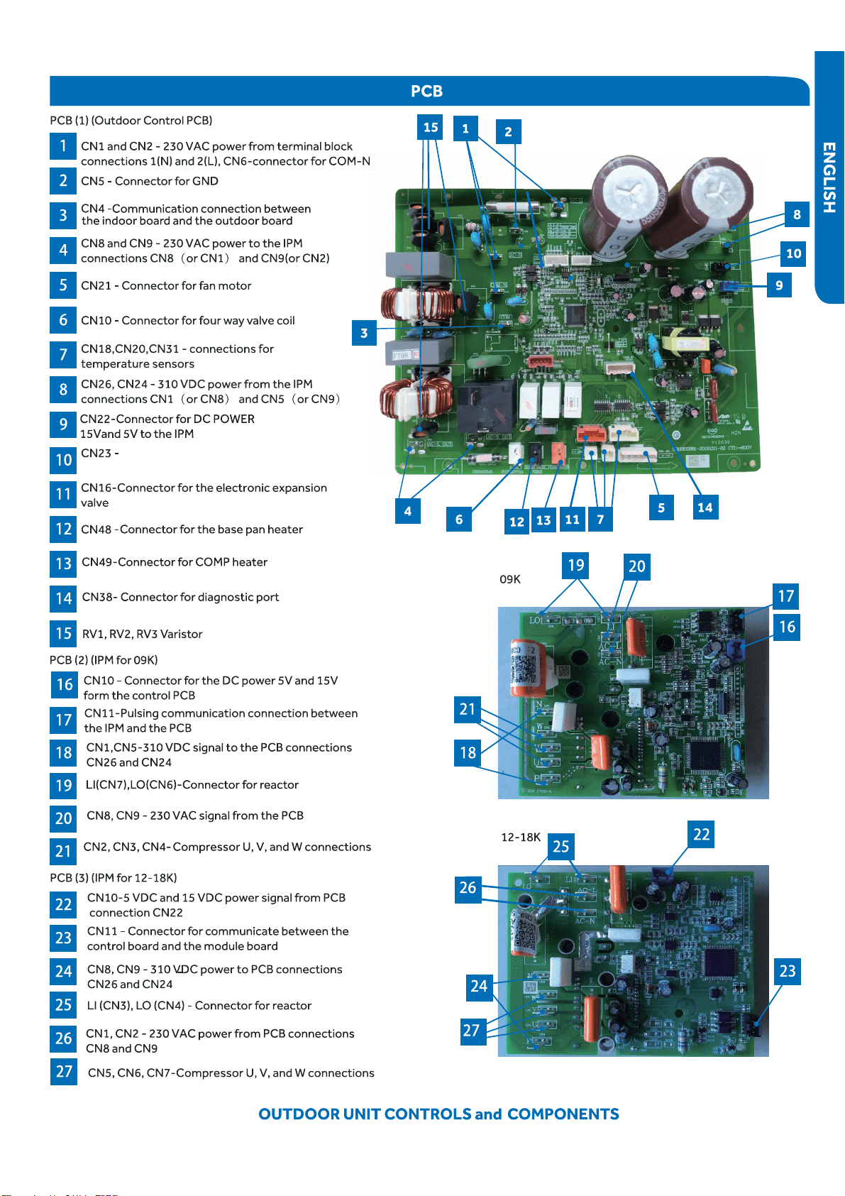
85
5VDC and 15VDC pulsing communication
●
connection between the PCB and the IPM
PAGE
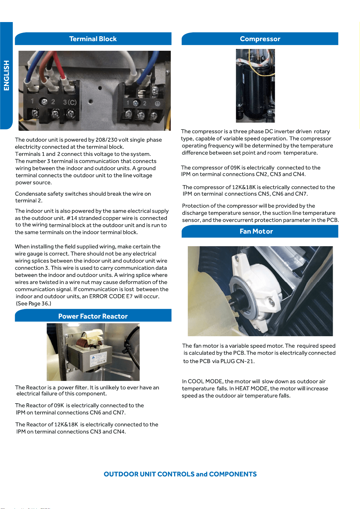
86PAGE
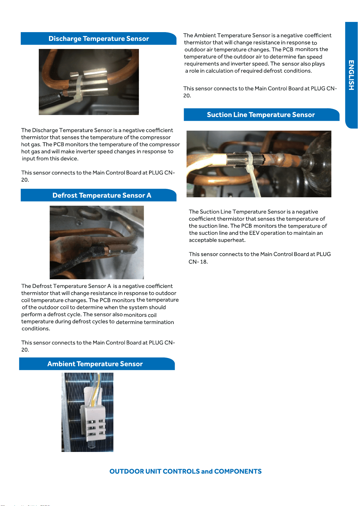
87PAGE
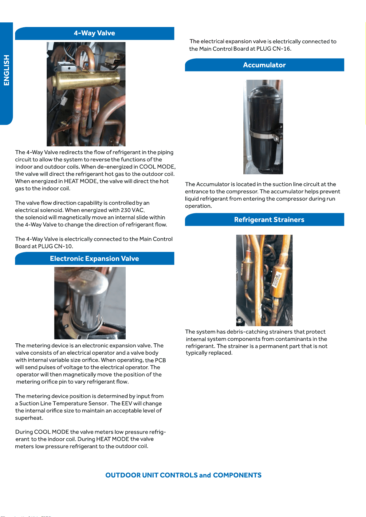
88PAGE
89
90
90
91
92
92
92
92
93
93
93
94
PAGE
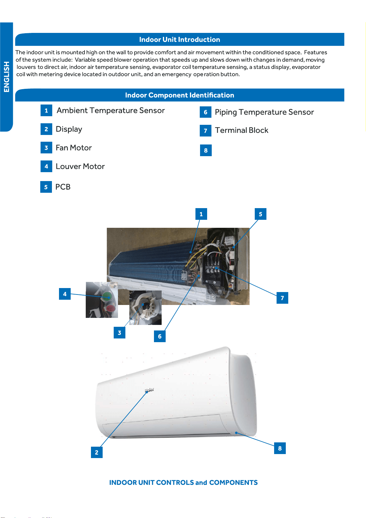
90
Emergency Button
PAGE
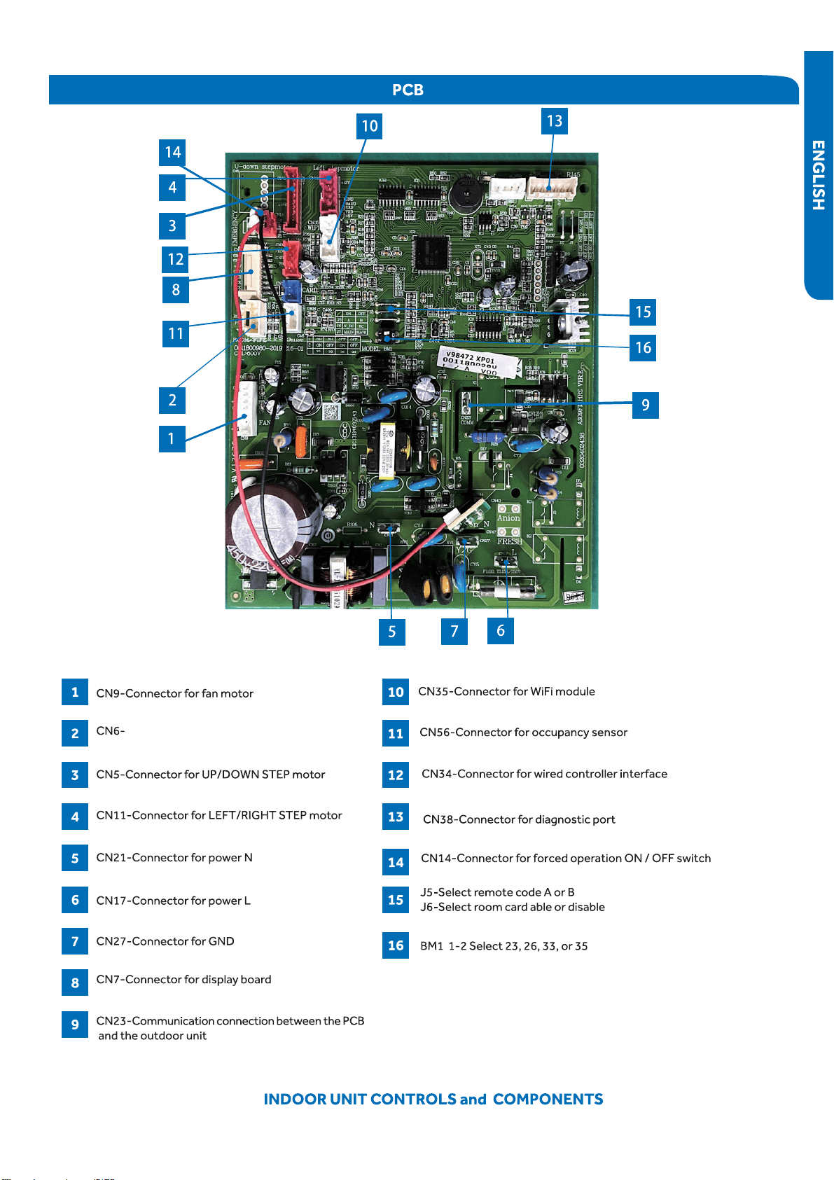
91
Connector for coil temperature sensor
●
and room temperature sensor
PAGE
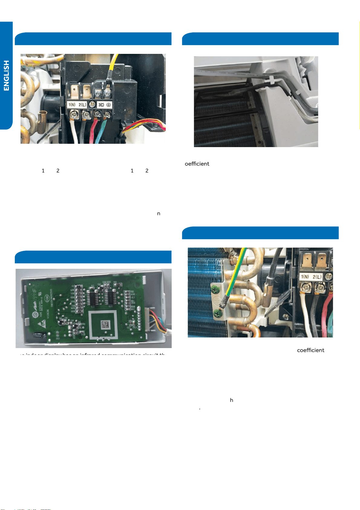
92 INDOOR UNIT CONTROLS and COMPONENTS
Terminal Block
Displ
●
ay
T
he
unit
terminal
block
receives
electrical
p
o
wer
from the
outdoor
unit.
T
here
are
4
c
onnections
f
or
electrical
wire
s
.
Terminals
1
and
2
are
c
onnected
t
o
terminals
1
and
2
of
the
outdoor
unit.
T
his
wiring
supplies
p
o
wer
t
o
the
indoor
unit.
Terminal
3
is
a
c
ommunication
wire.
T
he
indoor
unit
sends
indoor
air
tempe
r
a
t
ure,
c
oil
tempe
r
a
t
ure
and
tempe
r
a
t
ure
setpoint
in
f
ormation
t
o
the
outdoor
unit
on
this
wire.
If
a
splice
or
break
in
this
wire
is
present,
the
indoor
unit
will
n
o
t
be
able
t
o
c
ommunicate
with
the
outdoor
unit.
T
he
ER
R
OR
C
ODE
will
be
an
E7.
T
he
indoor
displ
a
y
has
an
inf
r
ared
c
ommunication
circuit
that
receives
ope
r
ating
c
ommands
f
r
om
the
rem
o
te
c
ont
r
ol.
T
his
displa
y
will
indicate
ope
r
ating
mode
s
,
er
r
or
c
ode
s
,
indoor
air
temper
a
t
ure,
timer
status, and power status.
Ambient Temperature Sensor
T
he
Ambient (room) Temperature Sensor
is
a
negative
c
thermis
t
or
that
will
decrease
in
resistance
with
increases
in
r
oom
air
tempe
r
a
t
ure.
T
he
sensor
is
located
on
a
clip
mounted
in the return air stream.
T
he
sensor
c
onnects
t
o
the
c
ont
r
ol
board
at
P
lug
CN-6.
Piping Temperature Sensor
T
he
P
iping
Tempe
r
a
ture
Sensor
is
a
negative
thermist
or
that
will
decrease
in
resistance
with
increases
in
c
oil
tempe
r
a
t
ure.
T
he
sensor
is
located
in
a
socket
soldered
t
o the sur
f
ace of the indoor
c
oil.
T
his
sensor
will
moni
t
or
the
tempe
r
a
t
ure
of
the
indoor
c
oil
in
b
o
th
c
ooling
and
heating
modes
of
ope
r
ation.
Should
abnormally
c
old
or
h
o
t
c
oil
tempe
r
a
t
ure
be
detected
by
this
sensor
,
sensor
sensor
the
s
y
stem
will
take
steps
t
o
c
orrect
the
c
ondition
or
report
an
ERR
OR
C
ODE.
T
he
sensor
c
onnects
t
o
the
c
ont
r
ol
board
at
P
lug
CN-6.
PAGE
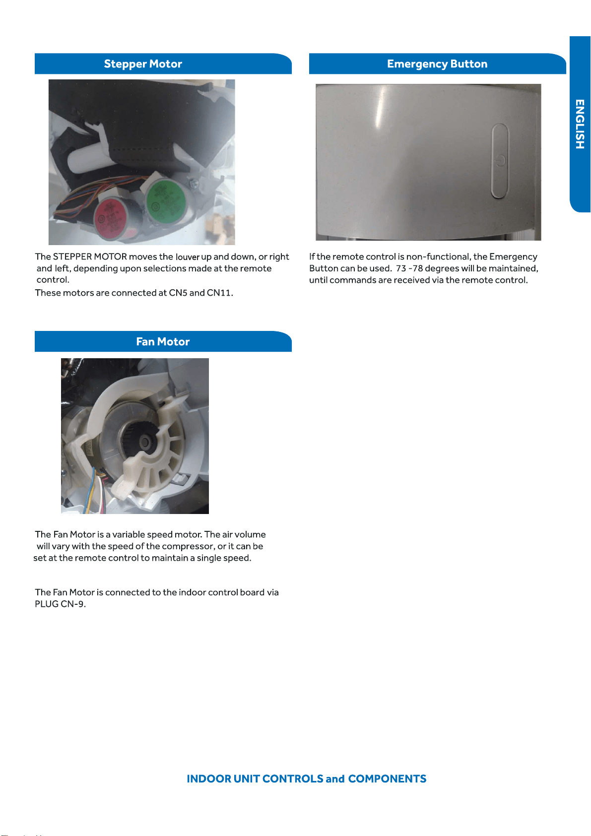
93PAGE
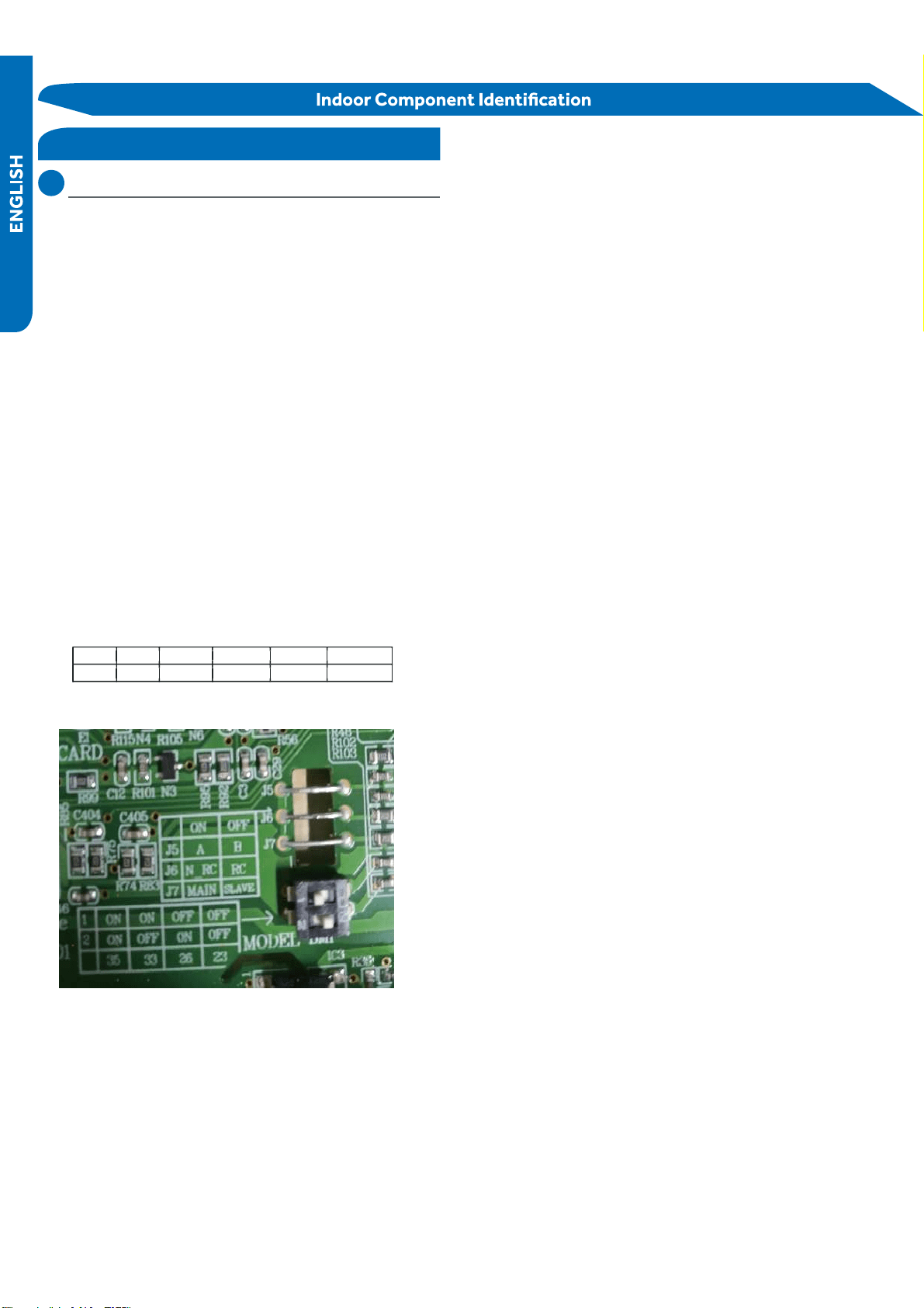
94 INDOOR UNIT CONTROLS and COMPONENTS
DIP
S
wi
t
ch
S
e
t
tings
T
he
PCB
has a set of DIP switches
●
that must be set when
replacing the PCB.
The replacement PCB is shipped with all switches set to the
OFF position.
S
witch
set
tings:
J6
Selects
r
oom
card
able
or
disable.
Normally
set
t
o
Set
t
o
when
used
in
c
onjunction
with
a
r
oom
card
inter
f
ace
utilized
in ho
tel
r
oom
s
.
S
W
-1
and SW-2 Selects EEPROM codes 23, 26, 33 and 35.
Set to
identify
the
t
onnage
of
the
unit.
Se
ttings:
9
K
(23
)
SW-
1
OF
F
S
W-2
OFF
12K
(26
)
S
W
-1
OF
F
S
W-2 ON
DIP Switch
connection
state.
the
disconnected state
J5
Selects
remote
code
A
or
B.
Normally
set
to
connection
state
for
code
A
operation.
If
two
indoor
units
are
used
in
the
same
area
and
the
user
wishes
to
control
them
separately,
switch
J5 of
the
sec
ond
unit
is
set
to
be
cut off
for
code
B
operation.
T
he
wireless
remote
for
the
second
unit
is
also
set
to
code
B.
PAGE
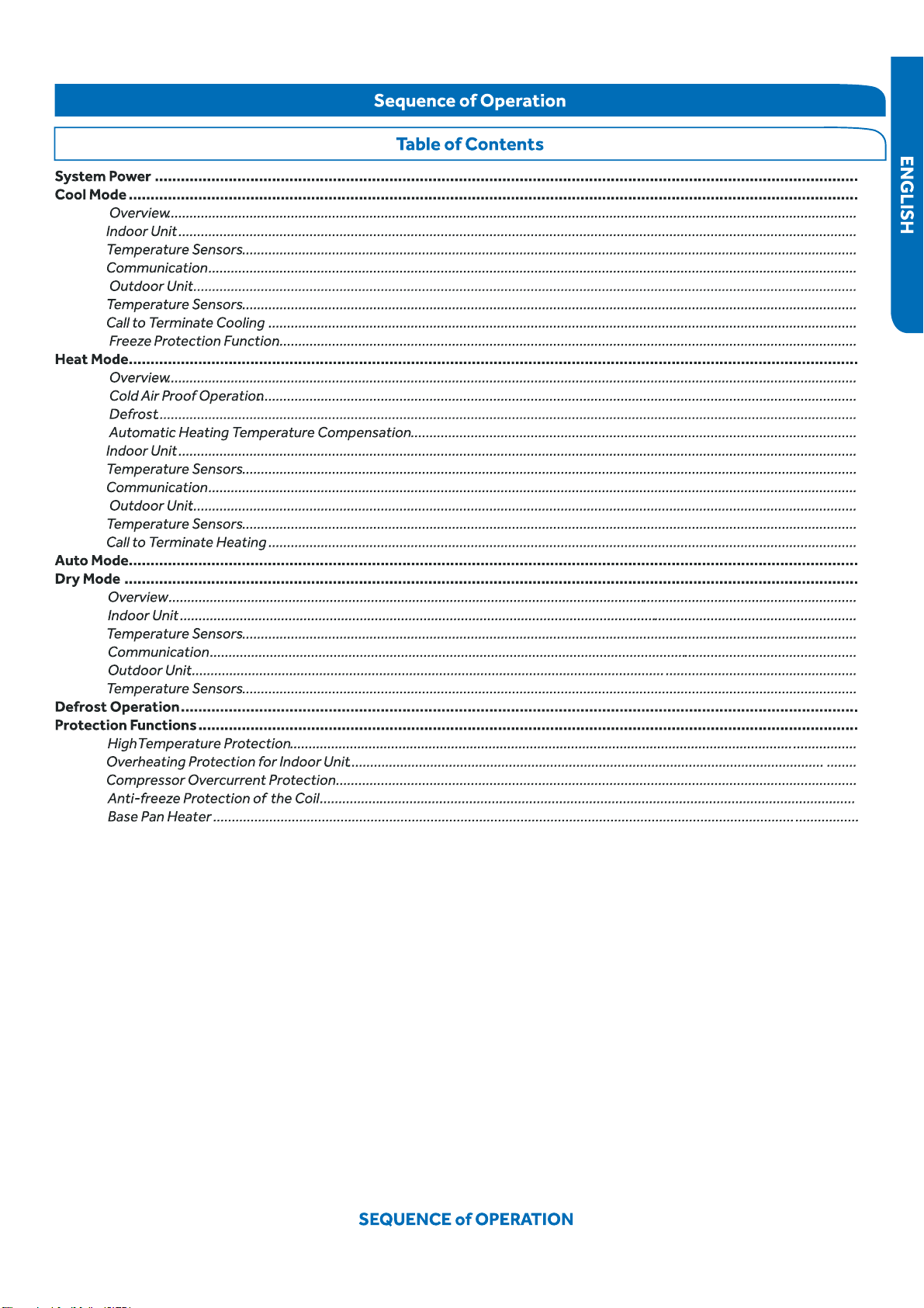
PAGE 95
102
101
100
100
99
99
99
98
97
97
96
102
96
Special Functions …………………………………………………………………………………………………………….….
Auto Restart ………………………………………………………………………………………………………………………………...............................................…
Timed Defrost……………………………………………………………………………………………………………………................................................…...……
Demand Defrost …………………………………………………………………………………………………………………...............................................………...
Indoor Temperature Display ……………………………………………………………………………………………...........................................…………….…..
Temperature Compensation………………………………………………………………………………………………..........................................………………
RJ45…………………………………………………………………………………………………………………………………......................................................……
9696
96
96
96
96
97
97
97
97
98
98
98
98
98
98
99
99
99
99
99
100
100
100
101
101
102
102
102
102
102
96 SEQUENCE of OPERATION
System Power
The 230 Volt AC power for the system connects to terminals
1(N), 2(L), and ground of the outdoor unit terminal block. This
terminal block also has terminals to connect power to the
indoor unit.
The voltage readings between terminals 1(N) and g
●
round, and
terminals 2(L) and ground should be 120 VAC. The voltage
reading between terminals 1(N) and 2(L) should be 230 VAC.
One additional connection on the terminal block (3) is for the
communication wire between the indoor and outdoor units.
NOTE: Mis-wiring of these connections may cause improper
operation or damage to system components.
Cool Mode
Overview
The temperature control range in
●
cooling mode is 60°F - 86°F.
The temperature set by the remote control and the indoor
unit ambient temperature sensor will determine if a call for
cooling is needed. If a call for
communicated from the indoor unit
●
to the outdoor unit. The
indoor unit louver will open using a stepper motor, and the
indoor fan will operate at the speed last set. The outdoor unit
will determine the position of the EEV and speed frequency
of the compressor. There can be a delay of up to 3 minutes
before the outdoor unit fan and compressor start.
The speed of the indoor fan can be controlled manually by
the user or automatically by the system. The speed can be
changed between LOW, MEDIUM, and HIGH.
(Tr= room temperature Ts= set tempe
●
rature)
High Speed: Tr
Medium Speed: Ts + 1.8°F Tr < Ts + 5.4°F
Low Speed: Tr Ts + 1.8°F or when the sensor is
There will be a 2 second delay when manually
●
controlling the
speed.
The outdoor unit temperature sensors: outdoor ambient,
defrost, suction line, and compressor discharge, used in
conjunction with the indoor temperature sensors, indoor
ambient and coil, provide information to the outdoor control
board to monitor the system and regulate the frequency of
the compressor, the EEV, and outdoor fan speed, to achieve
the desired room temperature.
followed by the outdoor fan. The indoor unit fan
will continue to run.
If the system detects a malfunction, it may shut down or
show an error code. This code will be shown on the indoor di-
Indoor Unit
To enter the cool mode, point the infrared remote control at
the indoor unit and press the power button, then press the
COOL mode button if not already set to cool mode.
The signals received by the infrared receiver are relayed to
the main board of the indoor unit to turn the system on and
set it to cool mode.
The indoor will illuminate the display, indicating
the set temperature and current status of the unit.
The to open the louver to
either a stationary position, or one of several oscillating
modes.
As the louver opens, the indoor unit main board will power up
the indoor fan motor, operating the fan at the speed last set.
The indoor fan motor has a feedback circuit which provides
the indoor unit main board with information for controlling
the speed of the fan motor.
Temperature Sensors
The indoor unit has two sensors that provide temperature
information to the main board. The sensors: an indoor ambi-
ent temperature sensor, and pipe temperature sensor, are
used for controlling the system during cool mode.
The resistance values of the sensors will vary with tempera-
ture. The resistance to temperature values can be found
to the sensor
being checked.
Communication
The indoor and outdoor unit main boards communicate via a
digital signal on the wire connected to terminal 3 of each unit.
A splice or break in this wire will cause a communication error.
When a command is received from the remote control, the
indoor unit main board communicates with the outdoor unit
main board to perform the requested function.
Outdoor Unit
Upon a request for cooling, the outdoor unit main board ap-
plies power to the outdoor fan motor
and compressor. Depending on system cycling, there may
be up to a 3 minute wait period before the compressor and
outdoor fan start.
If the room temperature is less than the set temperature,
yet higher than 2°F below the set temperature, the system
will adjust the speed of the compressor automatically.
Ts + 5.4°F
>=
The predetermined conditions for automatic control are
as follows:
PAGE
97
SEQUENCE of OPERATION
The outdoor unit main board also controls the position of the
EEV (Electronic Expansion Valve)
to regulate the ow of refrigerant to the indoor unit evapora-
tor coil.
Temperature Sensors
Call to Terminate Cooling
●
The system wil
●
l terminate cooling when the indoor ambient
temperature sensor is equal to or lower than 2°F of the room
set temperature. The indoor
●
control board will communicate
to the outdoor control board to de-energize the compressor.
The outdoor fan will run for 60 seconds before stopping.
The indoor fan motor and louver will continue operating after
cooling has been terminated.
●
To stop cool mode, press the power button to turn the sys-
tem o , or change to another mode.
Freeze P
●
rotection Function
Heat Mode
Overview
The temperature control range in heating mode is 60°F - 86°F.
The temperature set by the remote control and the indoor
unit ambient temperature sensor will determine if a call for
heat is needed. If a call for heat is justi ed, a temperature
compensation adjustment is automatically added to the
operating parameter and the call is communicated from the
indoor unit to the outdoor unit.
The indoor unit louver will open using a stepper motor. The
indoor fan will not operate at this time.
The outdoor unit will shift the 4-way valve to the heat mode
position and determine the position of the EEV and speed
(frequency) of the compressor. There can be a delay of up
to 3 minutes before the outdoor unit fan and compressor
start.
(Tr = room temperature Ts = set temperature)
If Tr Ts, the outdoor unit will operate and the indoor fan
operates in cold air prevention function
If Tr > Ts, the outdoor unit turns o and the indoor fan oper-
ates at heat residue sending mode.
If Tr < Ts, the outdoor unit will restart and the indoor fan
operates in cold air proof mode.
The speed of the indoor fan can be controlled manually by
the user or automatically by the system. The speed can be
changed between HIGH, MEDIUM, and LOW. The predeter-
mined conditions for automatic control are as follows:
High Speed: Tr < Ts
Medium Speed: Ts Tr Ts + 4°F
Low Speed: Tr > Ts + 4°F
When the indoor fan is running in automatic mode when the
speed switches from high to low, the indoor fan will maintain
high speed for a period of 3 minutes before switching to low
speed.
Four temperature sensors located in the outdoor unit provide
temperature information to the outdoor unit main board for
control of the system during cool mode.
The outdoor ambient temperature sensor provides the
temperature of the air drawn into the condenser coil
The defrost temperature sensor provides the temperature
sensed at the output of the condenser coil.
The suction line temperature sensor provides the temperature
sensed at the incoming suction line pipe.
The compressor discharge sensor provides the temperature
sensed at the discharge pipe of the compressor.
When the compressor operates continuously for 10 seconds
and the temperature of the indoor coil has been below 32°F
for 10 seconds, the compressor will stop. The indoor unit fan
will continue to operate. When the temperature of the indoor
coil rises to 45°F for more than 3 minutes the compressor will
restart and the system will continue functioning.
Cold Air Proof Operation
At initial start of heat mode, indoor blower will not be turned
on immediately until indoor coil temperature senses a minimum
temperature. This period usually takes 30 seconds to 3
minutes depending on the outdoor temperature.
Set speed
Low speed
Light speed
Fan/off
Keep the high
speed. The fan
doesn’t stop
4 minutes after the indoor fan starts, the light or low speed
will swich to the set speed.
Residual heat sending: the indoor fan will operate on low
speed until the coil temperature reaches 77 degrees.
The outdoor unit temperature sensors: outdoor ambient,
defrost, suction line, and compressor discharge, used in
conjunction with the indoor coil and room temperature
77°F
°F
95
99 °F
PAGE
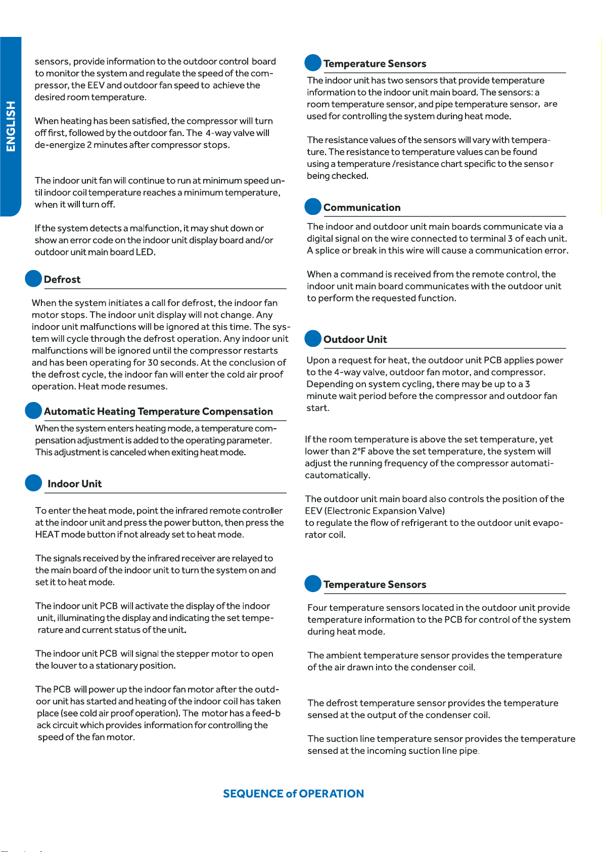
98
PAGE
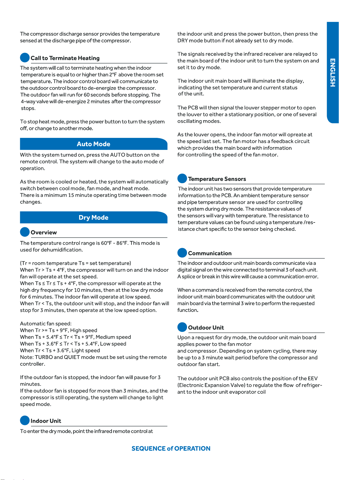
99
PAGE
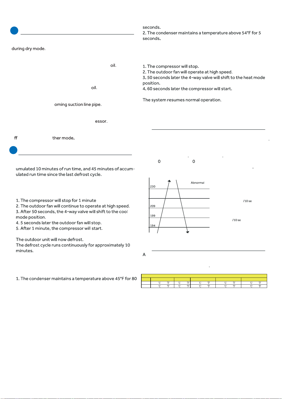
100 SEQUENCE of OPERATION
Temperature Sensors
To enter the defrost mode, the compressor must have acc-
When the defrost cycle begins, the following conditions take
place:
The system will exit the defrost cycle if any of the following
●
conditions are met:
Upon exiting the defrost cycle, the following conditions will
take place:
Protection Functions
1. Compressor High Temperature
The compressor discharge pipe sensor (exhaust temp)
senses the temperature of the refrigerant exiting the compressor
The sensed temperature received from the sensor
by the control circuitry will cause the compressor frequency
to increase or decrease (see chart below) If a temperature
of >= 23 °F is sensed for 2 seconds, an exhaust overheating
protection error code will be indicated at the outdoor unit
stop
Decreasing the frequency rapidly (1HZ/1second)
TTC (°F)
°F
212°F
°F
°F
°F
Decreasing the frequency slowly (1HZ conds)
The frequency doesn’t change
Increasing the frequency (1HZ conds)
Increasing the frequency (1HZ/1second)
2. Overheating Protection for Indoor Unit
sensor monitors coil temperature in both heating and cooling
modes, and causes the compressor to speed up, slow down, or
stop, according to the chart below
Four temperature sensors located in the outdoor unit provide
information to the outdoor unit PCB for control of the system
The outdoor ambient temperature sensor provides the
temperature of the air drawn into the condenser c
The defrost temperature sensor provides the temperature
sensed at the output of the condenser c
The suction line temperature sensor provides the tempera-
ture sensed at the inc
The compressor discharge sensor provides the temperature
sensed at the discharge pipe of the compr
To stop dry mode, press the power button to turn the system
o , or change to ano
Defrost Operation
Model Increasing slowly Holds value Decreasing slowly Decreasing rapidly Compressor stops
09K 40 /104 52 /126 57 /135 60 /140 63 /145
12K 40 /104 52 /126 57 /135 60 /140 63 /145
Overheating Protection for Indoor Unit
PAGE
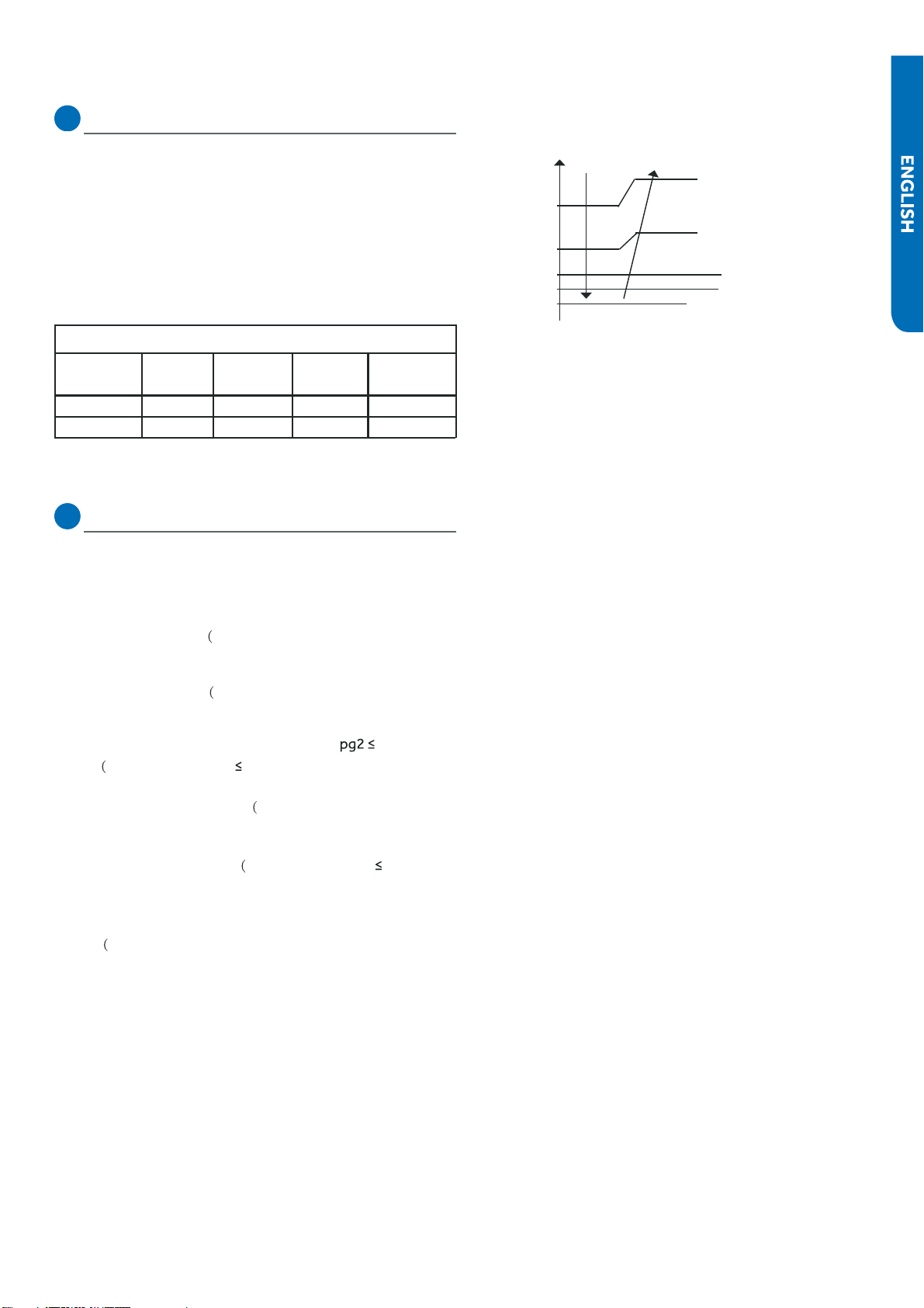
101
SEQUENCE of OPERATION
52°F //
48°F //
43°F
Decreasing slowly
Decreasing rapidly
Stop
Keeping the frequency
Increasing slowly
32°F
Tpg1=37°F
Tpg2=41°F
Tpg3=45°F
Tpg4=48°F
3. Compressor Over-current Protection
If the current draw of the compressor at start-up is greater
than the values listed on the chart below for approximately 3
seconds, the compressor will stop.
After 3 minutes the
compressor will restart. If the over-current condition occurs
3 times in 20 minutes, the system will lock-out, and a code
will be indicated at the outdoor unit. It will be necessary to
remove power to the system to reset the lock-out condi-
tion.
Model Holds
value
Decrease
1Hz/10s
●
Decrease
1Hz/s
Over-current
point
09K 12A
10A9A8A
12K 12A
10A 9A 8A
4. Anti-freeze Protection of the Indoor Coil
●
The temperature sensed by the coil
sensor is used to dete-
rmine at what speed the compressor is to run to avoid the
coil temperature being too cold.
Tpg_indoor: indoor unit pipe sensor temperature
When Min(Tpg_indoor ,
●
Tpg_indoor+Ts)/2) <
Tpg1, the freq-
uency of the compressor decreases at the rate of 1HZ / 1
When Tpg_indoor begins to rise again, and T
Tpg3, the frequency of the
compressor does not change.
When Tpg3 <
frequency of the compressor increases at the rate of 1HZ / 10
second
Example: if
32°F sust-
ains for 2 minutes, the outdoor unit will stop and indicate an
underload malfunction code at the outdoor unit. The com-
pressor stops for a minimum of 3 minutes. When Min(Tpg_
indoor , Tpg_indoor+Ts)/2)>Tpg4, the compressor will
●
restart
Ts: outdoor unit Suction Line sensor temperature
second.
When Min(Tpg_indoor , Tpg_indoor+Ts)/2) <
Tpg2, the freq-
uency of the compressor decreases at the rate of 1HZ / 10
Min(Tpg_i-
ndoor , Tpg_indoor+Ts)/2)
Min(Tpg_indoor , Tpg_indoor+Ts)/2) <Tpg4, the
second.
Min(Tpg_indoor , Tpg_indoor+Ts)/2)
Current Overload Prodection
PAGE
102 SEQUENCE of OPERATION
Special Functions
Auto Restart
When this is enabled, the following functions will automatically
●
resumes after a power loss:
they will be canceled upon restart
●
Wired Controller:
Wireless Controller:
Timed Defrost
Cancel method:
Demand Defrost
●
Indoor Temperature Display
●
Temperature Compensation
●
, then set the temperature to
RJ45
PAGE
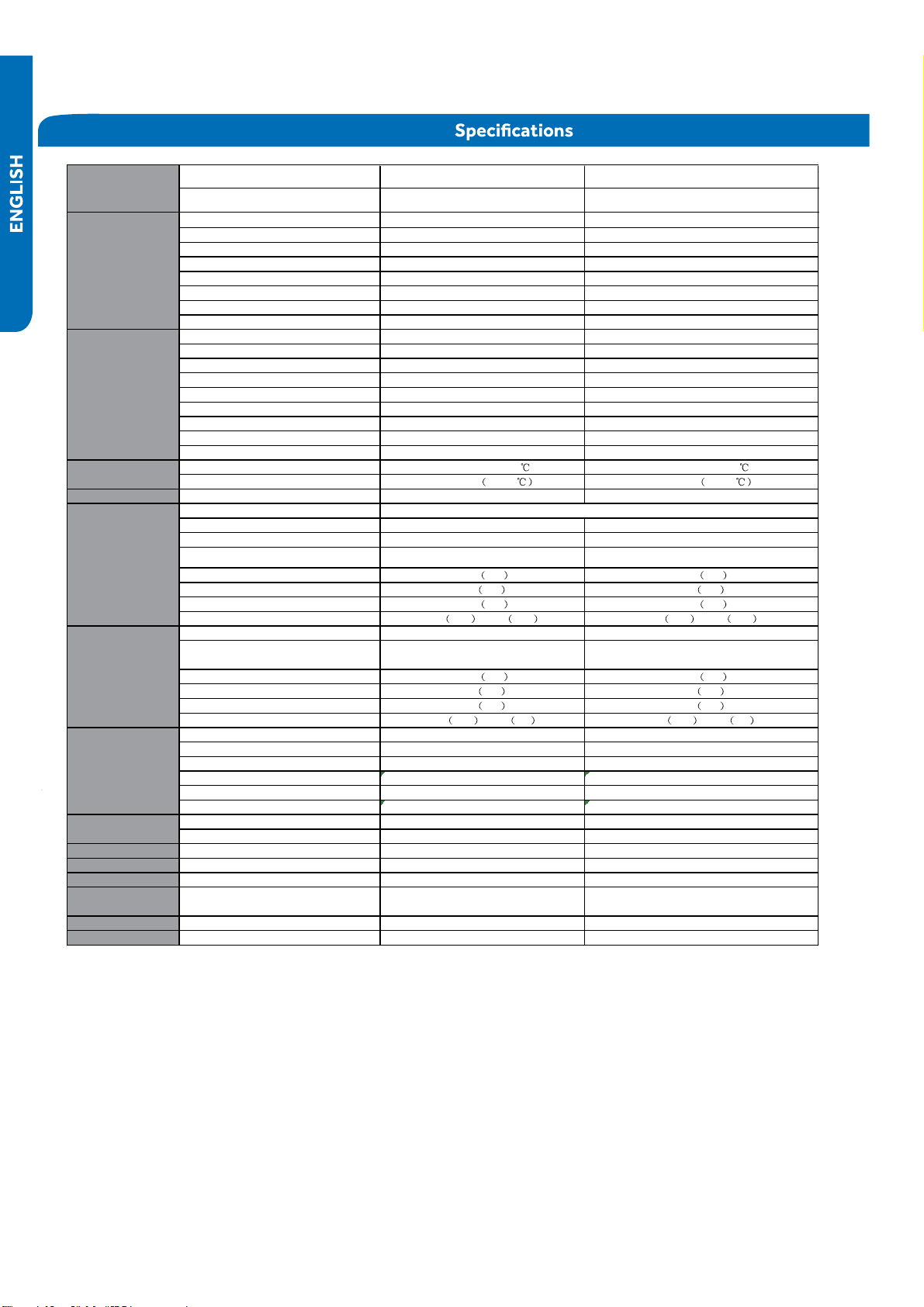
103
SYSTEM SPECIFICATIONS
System
O
●
utdoor 1U09TE2VHA/ASH109CRDWA 1U12TE2VHA/ASH112CRDWA
Indoor AW09TE2VHA/ASYW09CRDWA AW12TE2VHA/ASYW12CRDWA
Rated Capacity Btu/hr 9,000 12,000
Capacity Range Btu/hr 3,800~10,000 4,100~13000
Rated Power Input W800 1,100
SEER 18 18
EER 11.0 11.0
0F Cooling Without Wind BAffle 5000-->4000 5800.0
-4F Cooling with Wind Baffle 5000.0 6800.0
Moisture Removal Pt./h 2.30 2.60
Rated Heating Capacity 47°F Btu/hr 10,000 12,000
Heating Capacity Range Btu/hr 4,100~11,000 4,500~13,000
Rated Power Input W750 980
HSPF 10.0 10.0
Rated Heating Capacity 17°F Btu/hr 5,000 7,500
Max. Heating Capacity 17°F Btu/hr 9,000 10,000
Max. Heating Capacity 5°F Btu/hr 8,000 8,500
Max. Heating Capacity -4°F Btu/hr 6,500 7,500
NEEP Tier 1 Tier 1
Cooling °F(°C) 14°F~115°F(-10~46 ) 14°F~115°F(-10~46 )
Heating °F(°C) -4°F~75°F -20-24 -4°F~75°F -20-24
Power Supply Voltage, Cycle, Phase V/Hz/- 208/230-60-1 208/230-60-1
Compressor Type
Maximum Fuse Size A15 15
Minimum Circuit Amp A12 12
Outdoor Noise Level dB 51 53
Dimension: Height in (mm) 21.77 553 21.77 553
Dimension: Width in (mm) 31.5 800 31.5 800
Dimension: Depth in (mm) 10.83 275 10.83 275
Weight (Ship/Net)- lbs (kg) 76.1 34.5 /63.5 28.8 82.2 37.3 /69.7 31.6
F
●
an Speed Stages 5 + Auto 5 + Auto
Indoor Sound Level dB
(Turbo/High/Med/Low/Quiet) 44/39/35/32/28 44/40/37/34/28
Dimension: Height in (mm) 11.85 301 11.85 301
Dimension: Width in (mm) 33.7 856 33.7 856
Dimension: Depth in (mm) 7.72 196 7.72 196
Weight (Ship/Net)- lbs (kg) 26.9 12.2 /21.2 9.6 26.9 12.2 /21.2 9.6
Connections Flare Flare
Liquid O.D. in 1/4 1/4
Suction O.D. in 3/8 3/8
Factory Charge Oz 32.8 40.6
Maximum Line Length Ft / m 66/20 66/20
Maximum Height Ft / m 33/10 33/10
Ship with YR-HG (Haier or GE logo) YR-HG (Haier or GE logo)
Compatible Cool only (No logo) Cool only (No logo)
WiFi/App - Haier Built-in Built-in Built-in
WiFi/App - GE Built-in Built-in Built-in
Wind baffle Compatible QAWB41A QAWB41A
Wired controller Compatible Compatible with YR-E16b and
QACT17A/ACT17CWA with WK-B
Compatible with YR-E16b and
QACT17A/ACT17CWA with WK-B
Advanced Serivce GE3 Built-in Built-in
Important Features S
●
elf-Clean Indoor and Outdoor via APP Indoor and Outdoor via APP
Model Name
Remote controller
DC Inverter Driven Rotary
Refrigerate Line
Cooling
Operating Range
Outdoor Unit
Indoor Unit
Heating
PAGE

Check This First Outdoor Unit ....................................................................................................................................................105
Check This First Indoor Unit ......................................................................................................................................................106
Wiring Diagram Reference...................................................................................................... ............................. ......................107
F1/LED1: 2 Flash
F2/LED1: 24 Flash ....................................................................................................................................................................110
F3/LED1: 4 Flash .............................................................................. .......................................................................................112
F4/LED1: 8 Flash .............................................................................................. ........................................................................116
F6/LED1: 12 Flash
F7/LED1: 11 Flash
F21/LED1: 10 Flash
F25/LED1: 13 Flash
E1/LED1: No Flash
E2/LED1: No Flash ....................................................................................................................................................................116
F6/LED1: 12 Flash, F7/LED1: 11 Flash, F21/LED1: 10 Flash, F25/LED1: 13 Flash,
E1/LED1: No Flash, E2/LED1: No Flash................................................ ......................................................................................117
F8/LED1: 9 Flash .............................................................................................................................................. .........................118
F11/LED1: 18 Flash .......................................................................................................................................... .........................120
F12/LED1: 1 Flash ............................................................................................................................................. ........................122
E5/LED1: 22 Flash............................ ..........................................................................................................................................123
E7/LED1: 15 Flash ................................................................................................................................................... ..................125
Error Code (Indoor)
E14 ................................................................................................................. ..........................................................................128
Checking System Components....................................... ........................................................................ ............. .......................130·
Error Code (Indoor/outdoor)........................................................................................ ..............................................................108
104ERROR CODES and Troubleshooting
PAGE
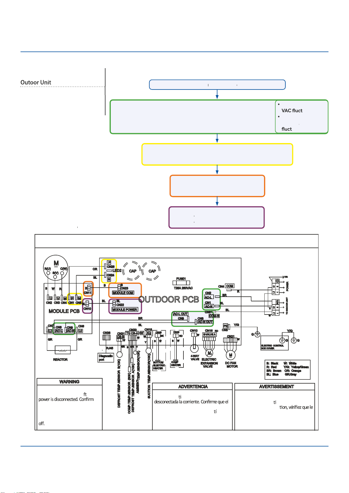
105
Troubleshooting
O
●
UTDOOR UNIT WIRING DIAGRAM
COMPRESSOR
E
●
lectrical Shock Hazard
Capacitor retains charge a er
voltage at capacitor has dissi
●
pated
(<10V DC) with hand held voltmeter
before servicing. LED2 light
between CN24 and CN26 should be
Riesgo de Descarga Eléctrica
El capacitor re ene carga una vez
voltaje del capacitor se haya disipado (<10V
DC) apoyando la mano sobre el vol metro
antes de realizar el servicio técnico. La luz
LED2 que se encuentra entre CN24 y CN26
deberá estar apagada.
Risque de choc électrique
Le condensateur conserve sa charge après la
coupure de l’alimenta on électrique. Avant
de procéder à une répara
courant au condensateur s’est dissipé
(<10 VCC) à l’aide d’un voltmètre manuel. Le
voyant LED2 entre CN24 et CN26 doit être
éteint.
0011509127B
Check This First
Models:
1U09TE2VHA
1U12TE2VHA
ASH109CRDWA
ASH112CRDWA
Line
v
oltage
a
v
ailable at:
1.
TERMINAL
S
TRIP - 1(N) & 2 (L)
2.
A
C
-L & A
C
-N at the PCB - CN2 & CN1
3.
A
C
-L OUT & A
C
-N OUT at the PCB - CN8 & CN9
4.
A
C
-L & A
C
-N at the I
P
M -CN8 & CN9 (9K) / CN1 & CN2 (12K/18K)
310+ VDC
a
v
ailable at:
1.
P & N at the I
P
M - CN1 & CN5 (9K) / CN8 & CN9 (12K/18K)
2.
P & N at the PCB - CN24 & CN26
Module
C
OM 5-G-15 VDC
a
v
ailable at:
1.
CN23 at the PCB
2.
CN11 at the I
P
M
Module p
o
w
er 5-G-15 VDC
a
v
ailable at:
1.
CN22
A
T THE PCB
A
A
2.
CN10
A
T THE I
A
A
P
M
1 (N) and 3 (C): 0-80
uating
2 (L) and 3 (C):
0-140
V
A
V
V
C
uating
Wiring Diag
r
am
R
e
f
e
f
f
r
en
c
e
Conditions Needed for Basic Operation
3-minu
t
es
of
time
del
a
y
f
r
f
f
om
the
call
f
or
f
f
heating
or
c
ooling
ERROR CODES and Troubleshooting PAGE
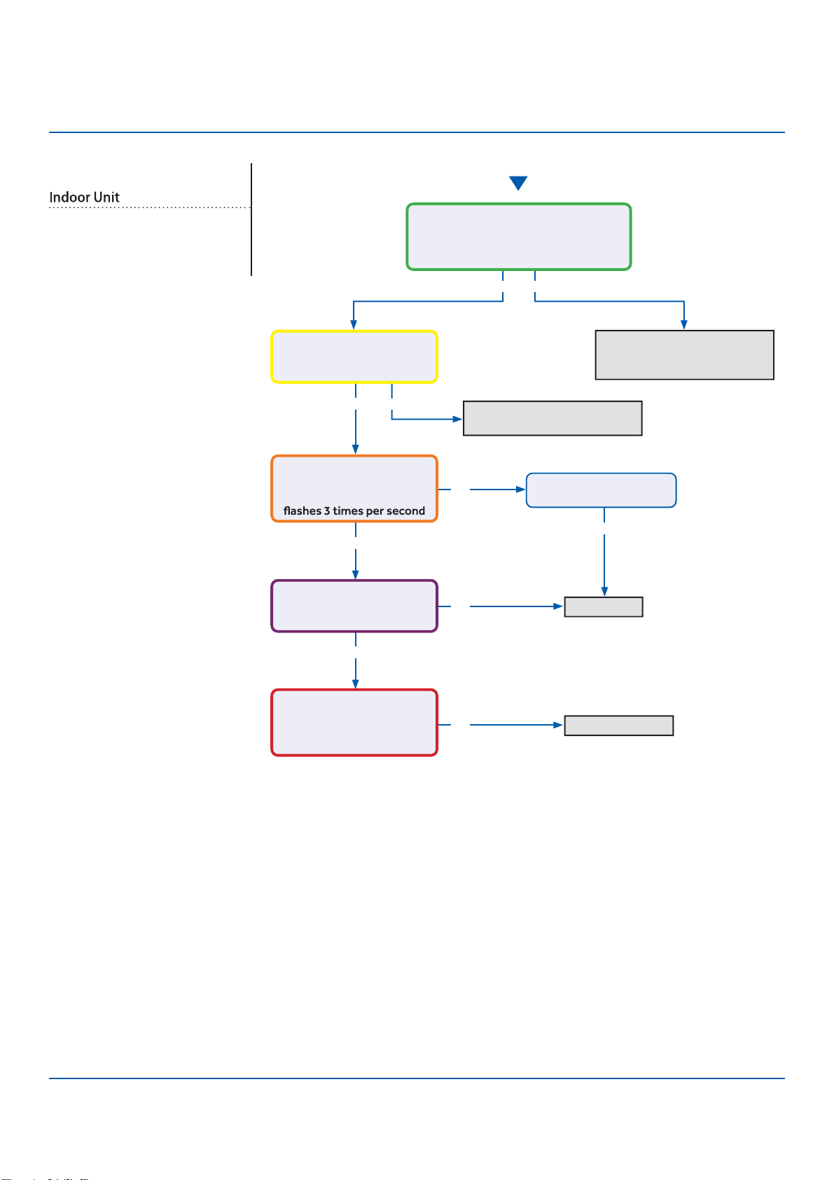
106
Troubleshooting
Start
See reverse side for
wiring diagram and
relevant color-coded
test positions.
Y
●
es
Y
●
es
Yes
Y
●
es
No
No
No
Yes No
No
Determine source of lost
power from OD unit or phase
imbalance from building power
Determine source of lost
communication from OD unit
Replace PCB
Replace sensor
There is 230 VAC (+/- 10%) at terminal
strip connections 1(N) and 2(L), and
no more than a 2% deviation between
each leg and ground?
There is a pulsing 0 to 80
VAC between terminal strip
connections 1(N) and 3(C)?
There is 230 VAC at
terminals CN17 and CN21
on the PCB, and the LED
There is 5 VDC at CN6
across both sets of black
sensor wires?
The sensor resistance is
within 3% of the value listed
in the Service Manual sensor
resistance table?
Wiring and connections
are in good condition?
Check This First
Models:
AW09TE2VHA
AW12TE2VHA
ASYW09CRDWA
ASYW12CRDWA
ERROR CODES and Troubleshooting
PAGE
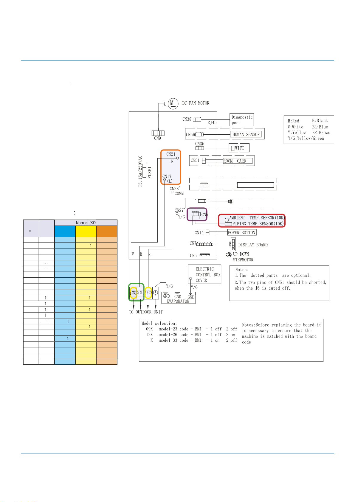
107
Troubleshooting
Check This First - Indoor Unit
Wiring Diag
r
am
R
e
f
e
f
f
r
en
c
e
Sensor
R
esi
s
tan
c
e
T
able
T
T
ERROR CODES and Troubleshooting
07
18K model-36 code - BM1 - 1 off 2 off
CN34
CN11
LEFT & RIGHT STEMP MOTOR
WIRED CONTROLLER
PAGE
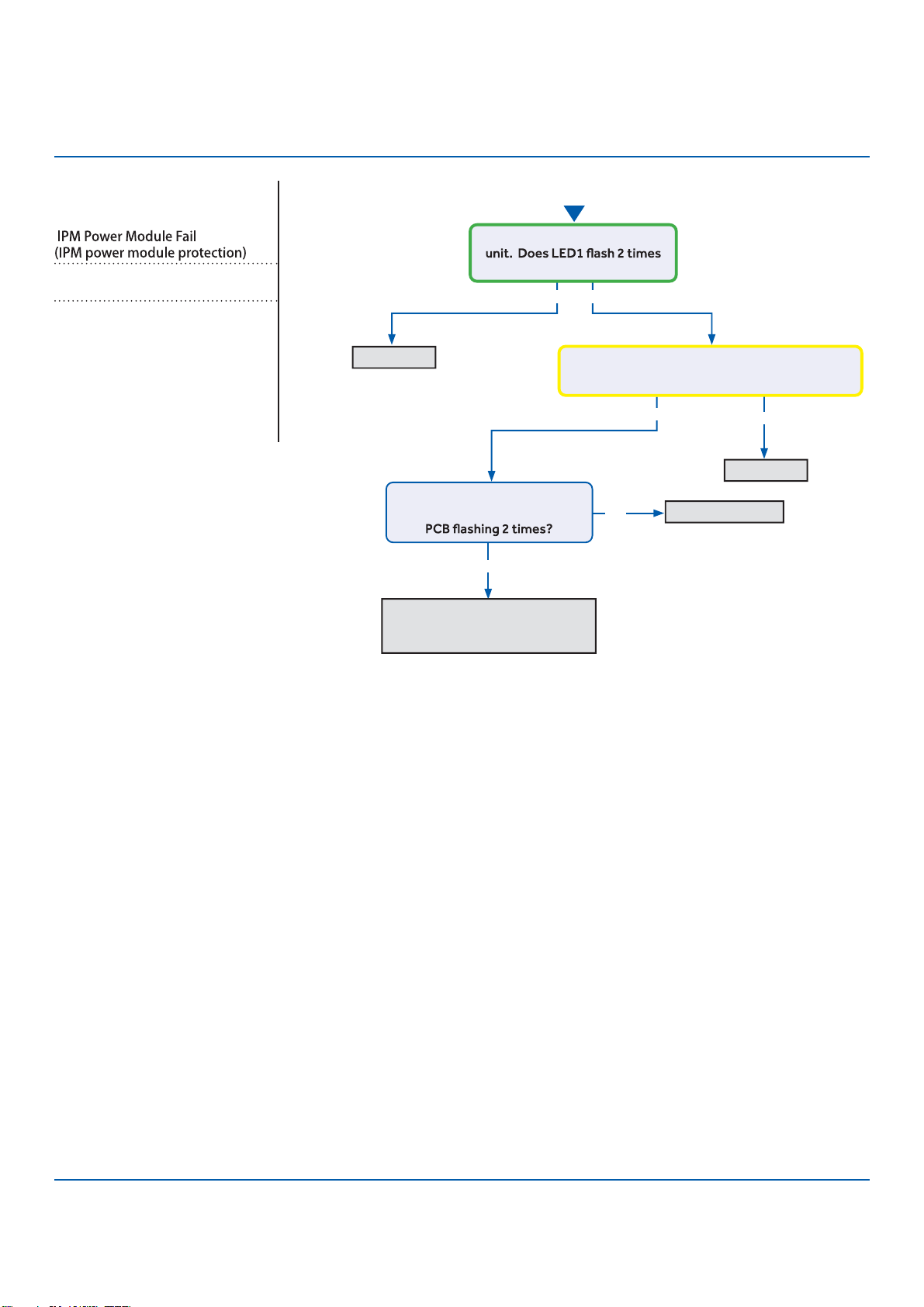
108
Troubleshooting
See reverse side for
wiring diagram and
relevant color-coded
test positions.
Error Code (Indoor/Outdoor)
F1/LED1: 2 Flash
Complete the “Check This First” F
●
low
Chart before continuing.
Models:
AW09TE2VHA
AW12TE2VHA
ASYW09CRDWA
ASYW12CRDWA
1U09TE2VHA
1U12TE2VHA
ASH109CRDWA
ASH112CRDWA
Y
●
es
No
No
Yes
Yes No
Start
Cycle power to the outdoor
before the compressor starts?
Compressor runs for 10 min.
and stops with LED in center of
DC voltage from P-U, P-V, P-W is 150-160VDC,
DC voltage from N-U, N-V, N-W 150-160VDC?
Replace IPM
Replace IPM
Normal operation
Check coil cleanliness,
EEV operation, compressor
windings, and refrigerant charge
ER
●
ROR CODES and Troubleshooting
PAGE
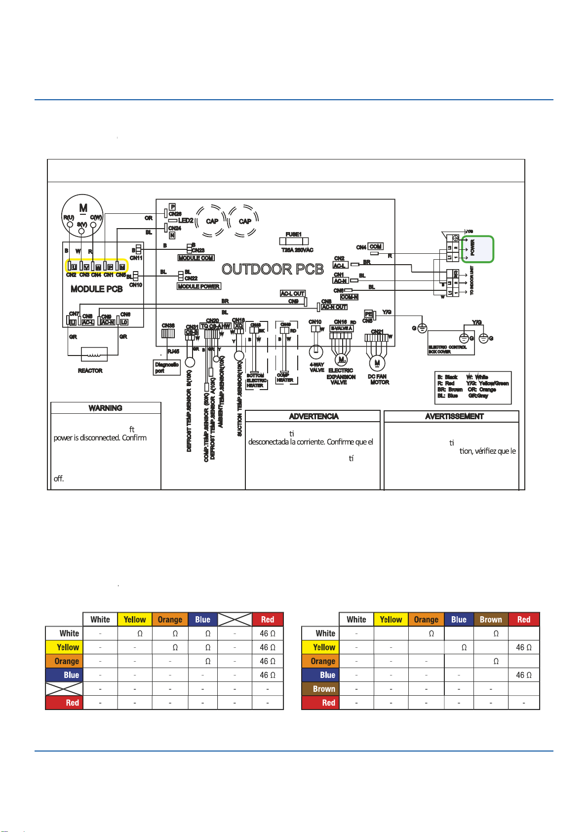
109
Troubleshooting
Error Code: F1/LED1: 2 Flash
Wiring Diag
r
am
R
e
f
e
f
f
r
en
c
e
OU
●
TDOOR UNIT WIRING DIAGRAM
COMPRESSOR
Electrical Shock Ha
●
zard
Capacitor retains charge a er
voltage at capacitor has dissi
●
pated
(<10V DC) with hand held voltmeter
before servicing. LED2 light
between CN24 and CN
●
26 should be
Riesgo de Descarga Eléctrica
El capacitor re ene carga una vez
voltaje del capacitor se haya disipado (<10V
DC) apoyando la mano sobre el vol metro
antes de realizar el servicio técnico. La luz
LED2 que se encuentra entre CN24 y CN26
deberá estar apagada.
Risque de choc électrique
Le condensateur conserve sa charge après la
coupure de l’alimenta on électrique. Avant
de procéder à une répara
courant au condensateur s’est dissipé
(<10 VCC) à l’aide d’un voltmètre manuel. Le
voyant LED2 entre CN24 et CN26 doit être
éteint.
0011509127B
EEV
R
esi
s
tan
c
e
V
alues
V
V
EEV (6-pin, 6 wi
r
e)
EEV (6-pin, 5 wi
r
e)
ERROR CODES and Troubleshooting PAGE
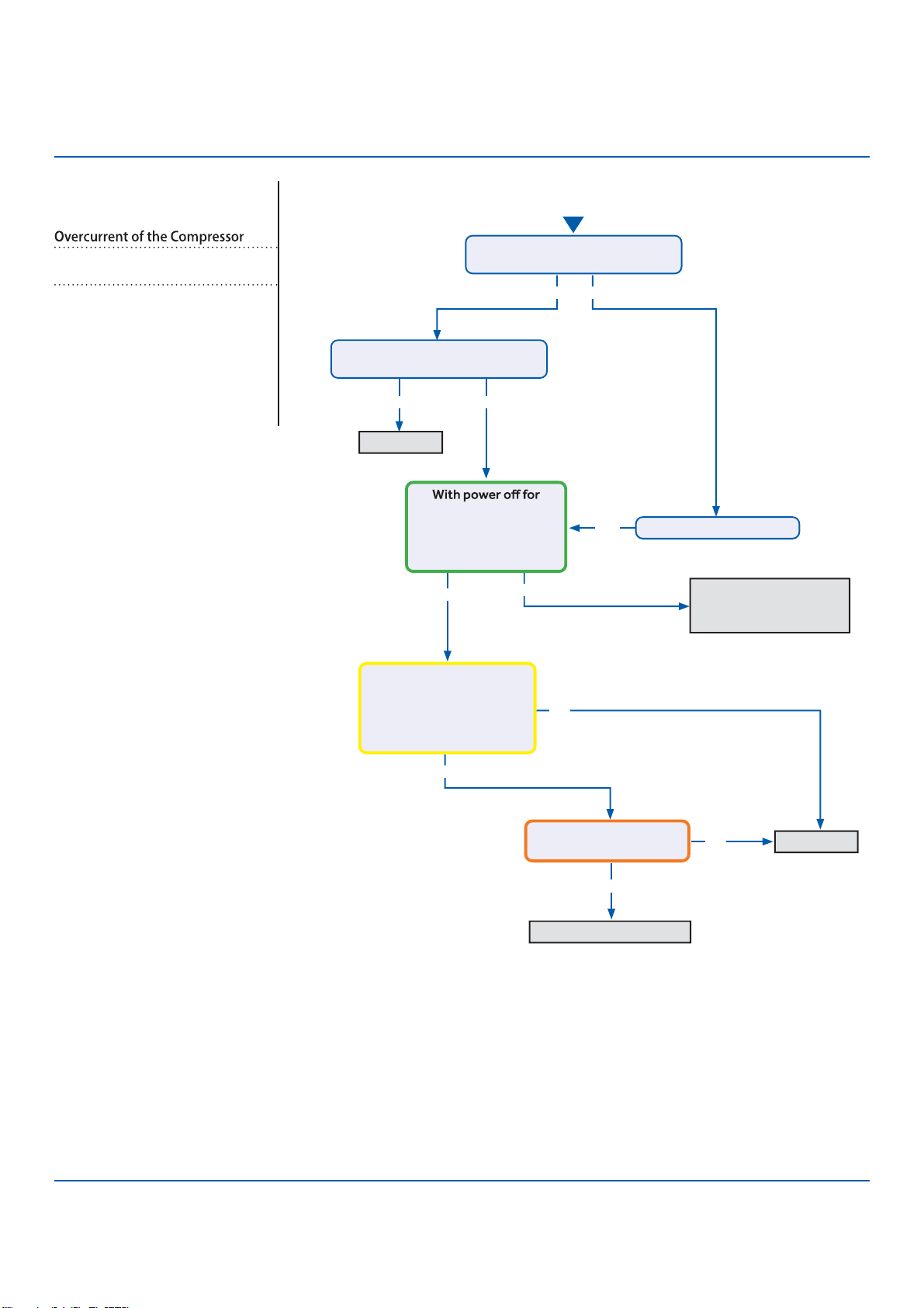
110
Troubleshooting
S
●
ee reverse side for
wiring diagram and
relevant color-coded
test positions.
Y
●
es
Yes No
Y
●
es
No
No
Yes
Yes
No
No
Yes
Continue to monitor;
the system is starting
under an abnormal load
Replace IPM
Replace IPM
Check refrigerant charge
Start
The set temperature is 5°F max.
from the room temperature?
Does the error code display
before the compressor starts?
5 min and back on,
compressor exceeds
over-current point in
Service Manual?
There is pulsing 50-200
VAC at compressor
terminals U, V, and W , read
from the terminal solder
points on the IPM?
There is 264-373 VDC at
P and N on the IPM?
Change set temperature
Error Code (Indoor/Outdoor)
F2/LED1: 24 Flash
Complete the “Check This First” Flow
Chart before continuing.
Models:
AW09TE2VHA
AW12TE2VHA
ASYW09CRDWA
ASYW12CRDWA
1U09TE2VHA
1U12TE2VHA
ASH109CRDWA
ASH112CRDWA
ERROR CODES and Troubleshooting
PAGE
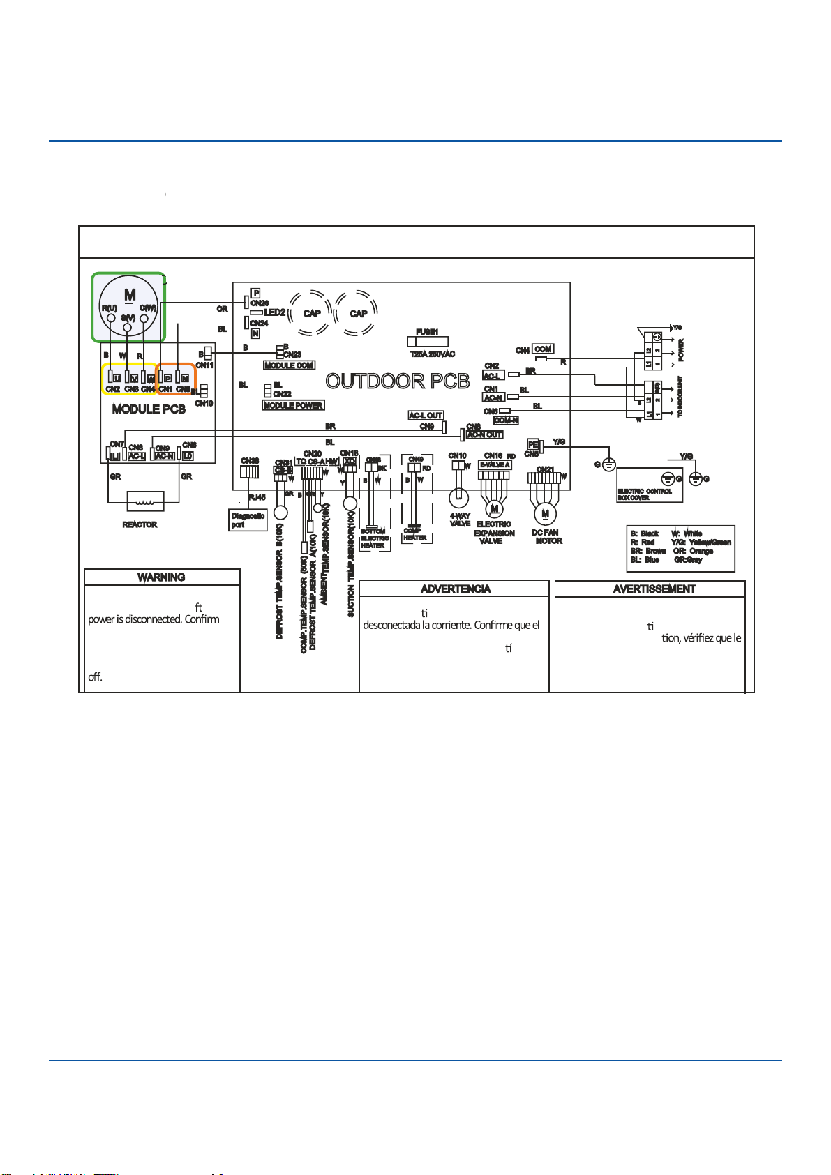
111
Troubleshooting
OUTDOOR UNIT WIRING DIAGRAM
COMPRESSOR
Electrical Shock Hazar
●
d
Capacitor retains charge a er
voltage at capacitor has dissipated
(<10V DC) with hand held voltmeter
before servicing. LED2 light
between CN24 and CN26 should be
Riesgo de Descarga Eléctrica
El capacitor re ene carga una vez
voltaje del capacitor se haya disipado (<10V
DC) apoyando la mano sobre el vol metro
antes de realizar el servicio técnico. La luz
LED2 que se encuentra entre CN24 y CN26
deberá estar apagada.
Risque de choc électrique
Le condensateur conserve sa charge après la
coupure de l’alimenta on électrique. Avant
de procéder à une répara
courant au condensateur s’est dissipé
(<10 VCC) à l’aide d’un voltmètre manuel. Le
voyant LED2 entre CN24 et CN26 doit être
éteint.
0011509127B
Error Code: F2/LED1: 24 Flash
Wiring Diag
r
am
R
e
f
e
f
f
r
en
c
e
C
O
O
ER
●
ROR CODES and Troubleshooting PAGE
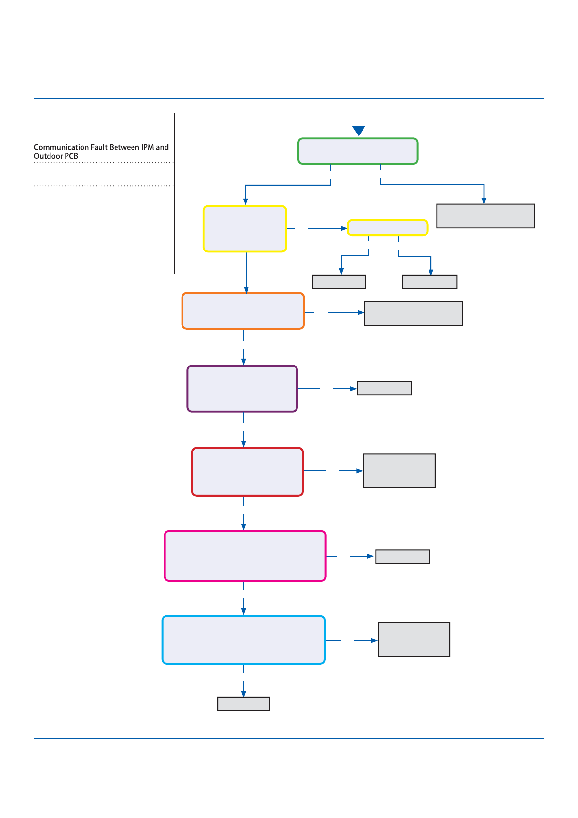
112
Troubleshooting
S
●
ee reverse side for
wiring diagram and
relevant color-coded
test positions.
Y
●
es
Yes
Y
●
es
Start
No
No
No
No
No
Line voltage at AC-L & AC-N
on the PCB (CN2 & CN1)?
Line voltage at AC-L & AC-N
on the IPM (9K CN8 & CN9 /
12K/18K CN1 & CN2)?
Module Power voltage -
CN22 on the PCB:
Across pins 1 & 2 = 5VDC
Across pins 2 & 3 = 15VDC?
Module Power voltage -
CN10 on the IPM
Across pins 1 & 2 = 5VDC
Across pins 2 & 3 = 15VDC?
Module Com voltage - CN23 on the PCB
With a call for Heating or Cooling,
Across pins 1 & 2 = 5VDC
Across pins 2 & 3 = 15VDC ?
Module Com voltage - CN11 on the IPM
With a call for Heating or Cooling,
Across pins 1 & 2 = 5VDC
Across pins 2 & 3 = 15VDC?
Yes
Yes
Yes
No
Yes No
Yes No
Check incoming power
from building
Replace PCB
Replace PCB
Replace fuse
Replace AC-L & AC-N
wiring harness
Replace module
power wiring
harness
Replace Module
COM Wiring
Harness
Replace PCB
R
●
eplace IPM
Fuse 1 is OK?
Line voltage at
AC-L OUT & AC-N
OUT on the PCB
(CN8 & CN9)?
Error Code (Indoor/Outdoor)
F3/LED1: 4 Flash
Complete the “Check This First” Flow
Chart before continuing.
Models:
AW09TE2VHA
AW12TE2VHA
ASYW09CRDWA
ASYW12CRDWA
1U09TE2VHA
1U12TE2VHA
ASH109CRDWA
ASH112CRDWA
ERROR CODES and Troubleshooting
PAGE
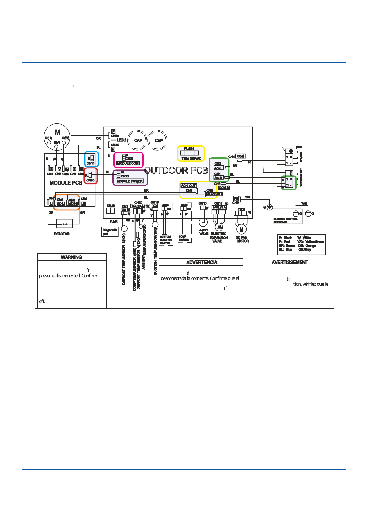
113
Troubleshooting
OUTDOOR UNIT WIRING DIAGRAM
COMPRESSOR
Electrical Shock H
●
azard
Capacitor retains charge a er
voltage at capacitor has dissipated
(<10V DC) with hand held vol
●
tmeter
before servicing. LED2 light
between CN24 and CN26 shou
●
ld be
Riesgo de Descarga Eléctrica
El capacitor re ene carga una vez
voltaje del capacitor se haya disipado (<10V
DC) apoyando la mano sobre el vol metro
antes de realizar el servicio técnico. La luz
LED2 que se encuentra entre CN24 y CN26
deberá estar apagada.
Risque de choc électrique
Le condensateur conserve sa charge après la
coupure de l’alimenta on électrique. Avant
de procéder à une répara
courant au condensateur s’est dissipé
(<10 VCC) à l’aide d’un voltmètre manuel. Le
voyant LED2 entre CN24 et CN26 doit être
éteint.
0011509127B
Error Code: F3/LED1: 4 Flash
Wiring Diag
r
am
R
e
f
e
f
f
r
en
c
e
ERROR CODES and Troubleshooting PAGE
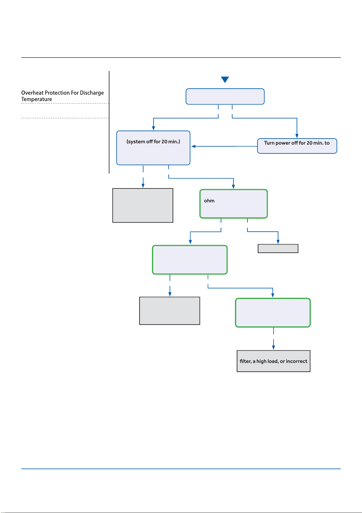
114
Troubleshooting
S
●
tart
See
●
reverse side for
wiring diagram and
relevant color-coded
test positions.
Y
●
es
Yes
Yes
Yes No
No
No
Yes No
Recover refrigerant,
remove moisture and
air from system, charge
with fresh refrigerant
to nameplate amount
Check for a fan motor
issue, restricted line
set or EEV, or lack of
refrigerant
Check for a plugged coil or
refrigerant charge
Replace sensor
The discharge line temperature
is below 230°F/110°C?
The discharge sensor
reading matches the
resistance table in the
Service Manual?
With system on, the
discharge sensor climbs to
230°F within a short time, and
the compressor stops?
With system on, the
discharge sensor climbs to
230°F after several minutes,
and the compressor stops?
allow the discharge line to cool
Refrigerant static test
indicates head pressure
converted to temperature is
higher than ambient?
Error Code (Indoor/Outdoor)
F4/LED1: 8 Flash
Complete the “Check This First” Flow
Chart before continuing.
Models:
AW09TE2VHA
AW12TE2VHA
ASYW09CRDWA
ASYW12CRDWA
1U09TE2VHA
1U12TE2VHA
ASH109CRDWA
ASH112CRDWA
ERROR CODES and Troubleshooting
PAGE
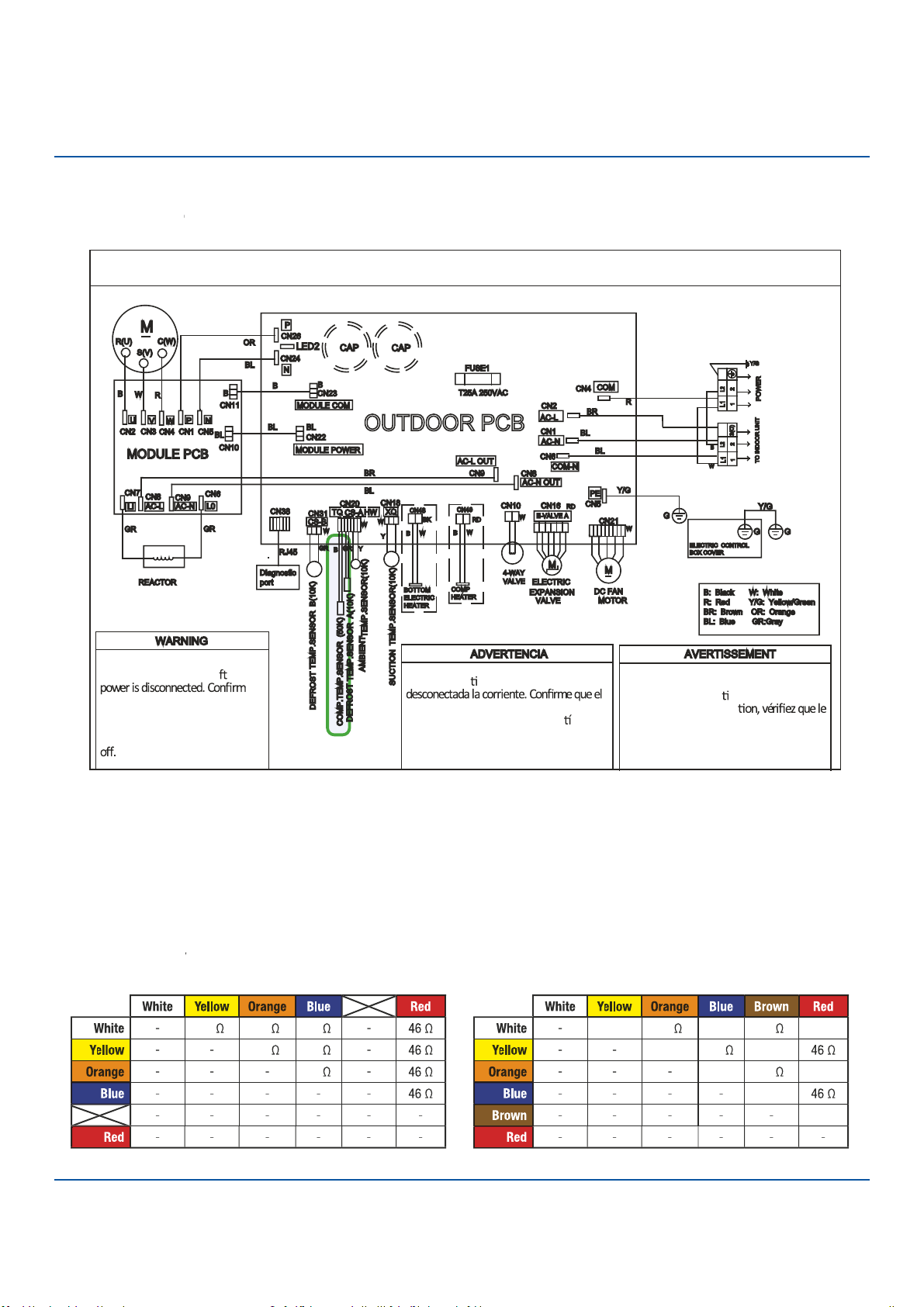
115
Troubleshooting
O
●
UTDOOR UNIT WIRING DIAGRAM
COMPRESSOR
Electrical Shock Haza
●
rd
Capacitor retains charge a er
voltage at capacitor has dissipated
(<10V DC) with hand held voltmeter
before servicing. LED2 light
between CN24 and CN26 should be
Riesgo de Descarga Eléctrica
El capacitor re ene carga una vez
voltaje del capacitor se haya disipado (<10V
DC) apoyando la mano sobre el vol metro
antes de realizar el servicio técnico. La luz
LED2 que se encuentra entre CN24 y CN26
d
●
eberá estar apagada.
Risque de choc électrique
Le condensateur conserve sa charge après la
coupure de l’alimenta on électrique. Avant
de procéder à une répara
courant au condensateur s’est dissipé
(<10 VCC) à l’aide d’un voltmètre manuel. Le
voyant LED2 entre CN24 et CN26 doit être
éteint.
0011509127B
Error Code: F4/LED1: 8 Flash
Wiring Diag
r
am
R
e
f
e
f
f
r
en
c
e
EEV
R
esi
s
tan
c
e
V
alues
V
V
EEV (6-pin, 6 wi
r
e)
EEV (6-pin, 5 wi
r
e)
ERROR CODES and Troubleshooting PAGE
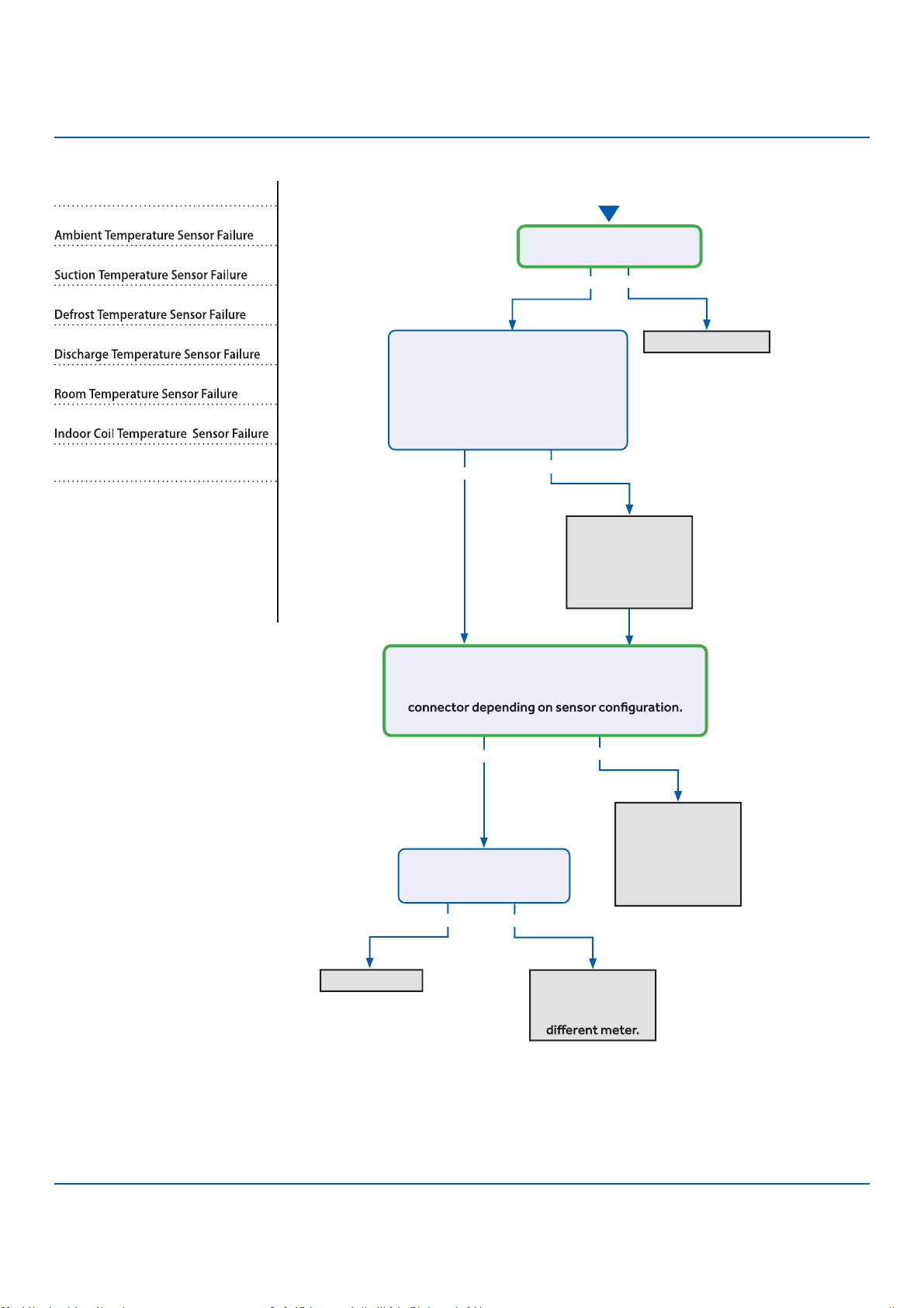
116
Troubleshooting
See reverse side for
wiring diagram, relevant
color-coded test
positions, and sensor
resistance values.
Error Codes (Indoor/Outdoor)
F6/LED1: 12 Flash
F7/LED1: 11 Flash
F21/LED1: 10 Flash
F25/LED1: 13 Flash
E1/LED1: No Flash
E2/LED1: No Flash
Complete the “Check This First” F
●
low
Chart before continuing.
Models:
AW09TE2VHA
AW12TE2VHA
ASYW09CRDWA
ASYW12CRDWA
1U09TE2VHA
1U12TE2VHA
ASH109CRDWA
ASH112CRDWA
Yes
Y
●
es
Y
●
es
Yes No
No
No
No
Re-seat connector
Replace sensor.
Go to next step
to test the board
as well before
replacing sensor.
Replace main
board. Replace
sensor as well if
resistance was
incorrect in the
previous step.
R
●
e-seat and
re-check sensor
resistance with a
Replace sensor
Start
Is connector plugged in and
seated securely?
Disconnect power and un-plug senor
connector from the board.
Check resistance across the set of
wires for the faulting sensor. Does
the resistance correspond to the
temperature located in the respective
chart ? (See Reverse side.)
Reconnect sensor to the board and re-apply power.
Check voltage between the two corresponding
solder joints or through the top of the Molex
Is the voltage ~5VDC?
Is the temperature at the
sensor out of operating
range (+/- 3%)?
ERROR CODES and Troubleshooting
PAGE
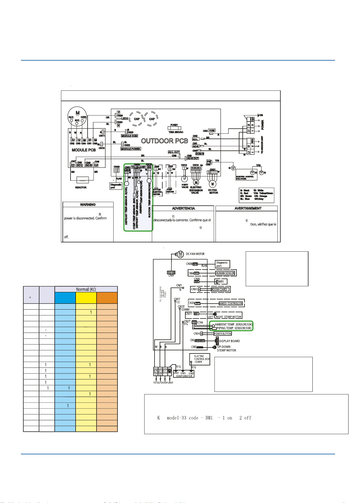
117
Troubleshooting
Out r ram
Electrical S
●
hock Hazard
Capacitor retains charge a er
voltage at capacito
●
r has dissipated
(<10V DC) with hand held voltmeter
before servicing. L
●
ED2 light
between CN24 and CN26 should be
OUTDOOR UNIT WIRING DIAGRAM
COMPRESSOR
Electrical Shock Hazard
Capacitor retains charge a er
voltage at capacitor has dissipated
(<10V DC) with hand held voltmeter
before servicing. LED2 light
between CN24 and CN26 should be
Riesgo de Descarga Eléctrica
El capacitor re ene carga una vez
voltaje del capacitor se haya disipado (<10V
DC) apoyando la mano sobre el vol metro
antes de realizar el servicio técnico. La luz
LED2 que se encuentra entre CN24 y CN26
deberá estar apagada.
Risque de choc électrique
Le condensateur conserve sa charge après la
coupure de l’alimenta on électrique. Avant
de procéder à une répara
courant au condensateur s’est dissipé
(<10 VCC) à l’aide d’un voltmètre manuel. Le
voyant LED2 entre CN24 et CN26 doit être
éteint.
0011509127B
Sensor
R
esi
s
tan
c
e Table
v
o
v
l
t
a
g
e
g
a
t
c
a
p
a
p
c
i
t
o
r
h
a
s
d
i
s
s
i
p
a
p
t
a
a
e
d
Error Code: F6/LED1: 12 Flash, F7/LED1: 11 Flash, F21/LED1: 10 Flash, F25/LED1: 13 Flash,
E1/LED1: No Flash, E2/LED1: No Flash
Wiring Diag
r
am
R
e
f
e
f
f
r
en
c
e
ERROR CODES and Troubleshooting
R:Red
W:White
Y:Yellow
Y/G:Yellow/Green
B:Black
BR:Brown
BL:Blue
Notes:
1.The dotted parts are optional.
2.The two pins of CN51 should be shorted,
when the J6 is cuted off.
Model selection:
09K model-23 code - BM1 - 1 off 2 off
12K model-26 code - BM1 - 1 off 2 on
Notes:Before replacing the board,it
is necessary to ensure that the
machine is matched with the board
code
07
18K model-36 code - BM1 - 1 off 2 off
PAGE
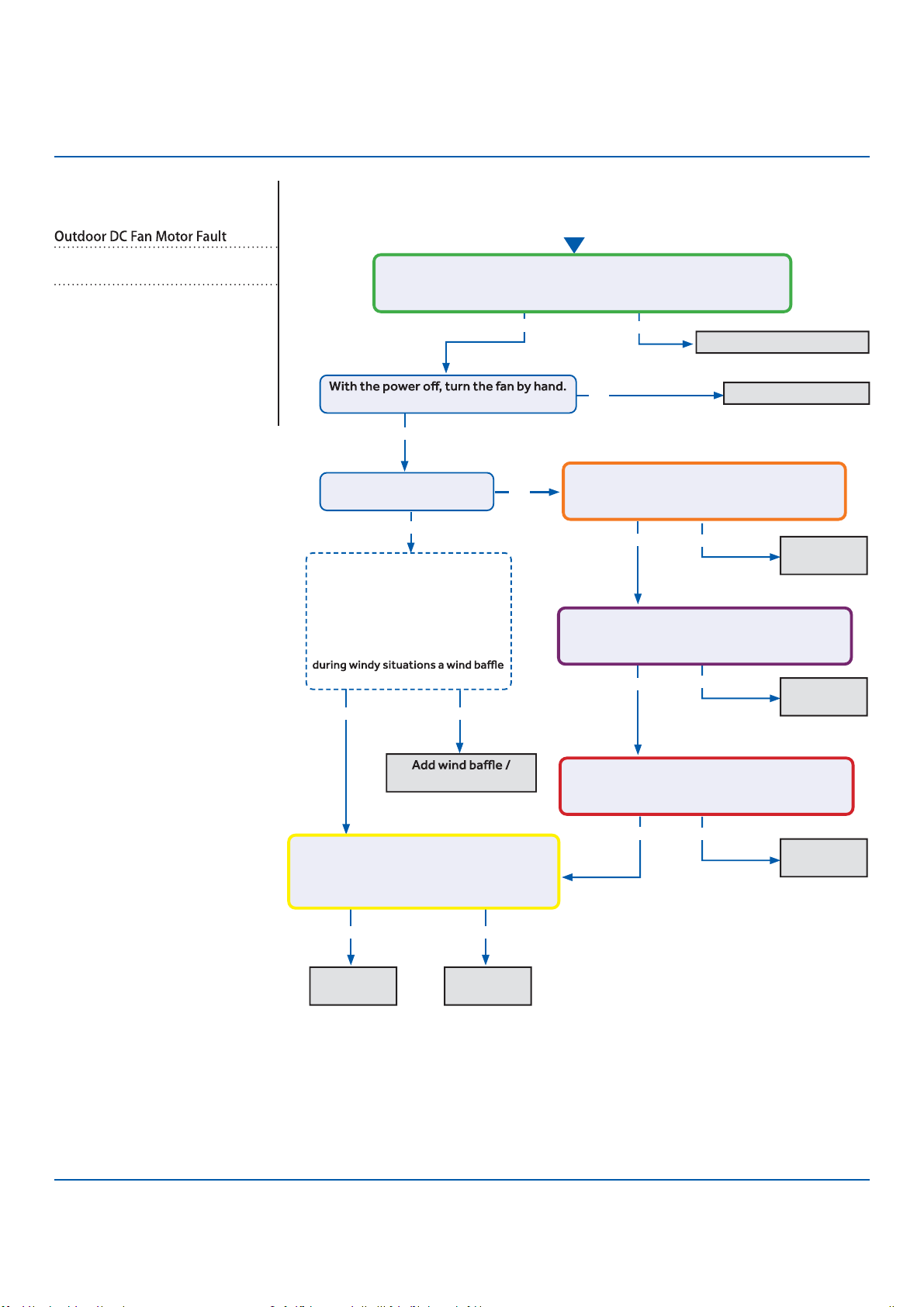
118
Troubleshooting
See reverse side for
wiring diagram and
relevant color-coded
test positions.
No
Error Code (Indoor/Outdoor)
F8/LED1: 9 Flash
Complete the “Check This First” Flow
Chart before continuing.
Models:
AW09TE2VHA
AW12TE2VHA
ASYW09CRDWA
ASYW12CRDWA
1U09TE2VHA
1U12TE2VHA
ASH109CRDWA
ASH112CRDWA
Yes
Y
●
es
Yes
Yes
No
●
Yes
No
Yes No
protection from wind.
Fix incoming power supply
Replace the fan motor
Replace the
fan motor.
Replace the
main board.
Start
Check the incoming voltage.
Is it 208/230VAC (+/- 10%) between L1/L2?
104/115VAC (+/- 10%) from L1 to GROUND and L2 to GROUND?
Does it move / rotate smoothly?
Re-apply power. Does the
fan come on and spin?
Measure DC voltage at fan motor plug
CN21 between the Pin 6 (BLUE) and Pin 3
(BLACK) wire while spinning the fan motor.
Does it generate 2~9VDC?
No
No
No
Replace the
main board.
Replace the
main board.
Replace the
main board.
Measure DC voltage at fan motor plug CN21
between Pin 1 (RED) and Pin 3 (BLACK).
Does it measure 300~380VDC (+/-10%)?
Measure DC voltage at fan motor plug CN21
between Pin 4 (WHITE) and Pin 3 (BLACK).
Does it measure between 13.5-16.5VDC?
Measure DC voltage at fan motor plug CN21
between Pin 5 (YELLOW) and Pin 3 (BLACK).
Does it measure between 2-6VDC?
Before going to the next step, is the
unit in an area susceptible to high
winds? High winds blowing into the
fan may cause added resistance
and subsequently lower fan speeds
enough to cause the unit to fault. If
this is the case the unit only faults
may need to be added.
Not Windy Windy
Yes
ERROR CODES and Troubleshooting
PAGE
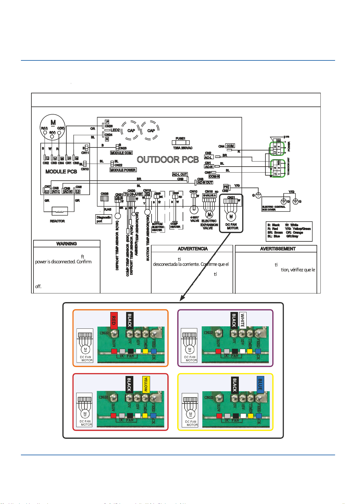
119
Troubleshooting
OUTDOOR UNIT WIRING DIAGRAM
COMPRESSOR
Electrical Shock Hazard
●
Capacitor retains charge a er
voltage at capacitor has dissipa
●
ted
(<10V DC) with hand held voltm
●
eter
before servicing. LED2 light
between CN24 and CN26 shoul
●
d be
Riesgo de Descarga Eléctrica
El capacitor re ene carga una vez
voltaje del capacitor se haya disipado (<10V
DC) apoyando la mano sobre el vol metro
antes de realizar el servicio técnico. La luz
LED2 que se encuentra entre CN24 y CN26
deberá estar apagada.
Risque de choc électrique
Le condensateur conserve sa charge après la
coupure de l’alimenta on électrique. Avant
de procéder à une répara
courant au condensateur s’est dissipé
(<10 VCC) à l’aide d’un voltmètre manuel. Le
voyant LED2 entre CN24 et CN26 doit être
éteint.
0011509127B
Error Code: F8/LED1: 9 Flash
Wiring Diag
r
am
R
e
f
e
f
f
r
en
c
e
c
t
c
r
i
e
z
y
a
d
o
b
r
v
i
c
i
r
a
r
r
a
d
a
1
3
4 5
6
/
1
3
4 5
6
/
1
3
4 5
6
/
1
3
4 5
6
/
ERROR CODES and Troubleshooting PAGE

120
Troubleshooting
Start
See reverse side for
wiring diag
●
ram and
relevant color-coded
test positions.
No
●
No
Yes
Momentary loss
of building power
or acceptable
power quality
Replace
compressor
R
●
eplace compressor
Replace IPM
Repair or
replace wiring or
connections
min. and turned back on,
the compressor runs?
A windings or grounding
check shows issues with
compressor?
There is 50-200 VAC
across the U, V, and W
solder points on the IPM?
The compressor wires are
on the correct terminals,
free of breaks and the
connections at both end
are secure?
There is substantially more than
5 VDC or 15 VDC pulsing at CN23
(MODULE COM) on the PCB?
Yes
Yes
Yes
Yes
No
No
Error Code (Indoor/Outdoor)
F11/LED1: 18 Flash
Complete the “Check This First” Flow
Chart before continuing.
Models:
AW09TE2VHA
AW12TE2VHA
ASYW09CRDWA
ASYW12CRDWA
1U09TE2VHA
1U12TE2VHA
ASH109CRDWA
ASH112CRDWA
ERROR CODES and Troubleshooting
PAGE
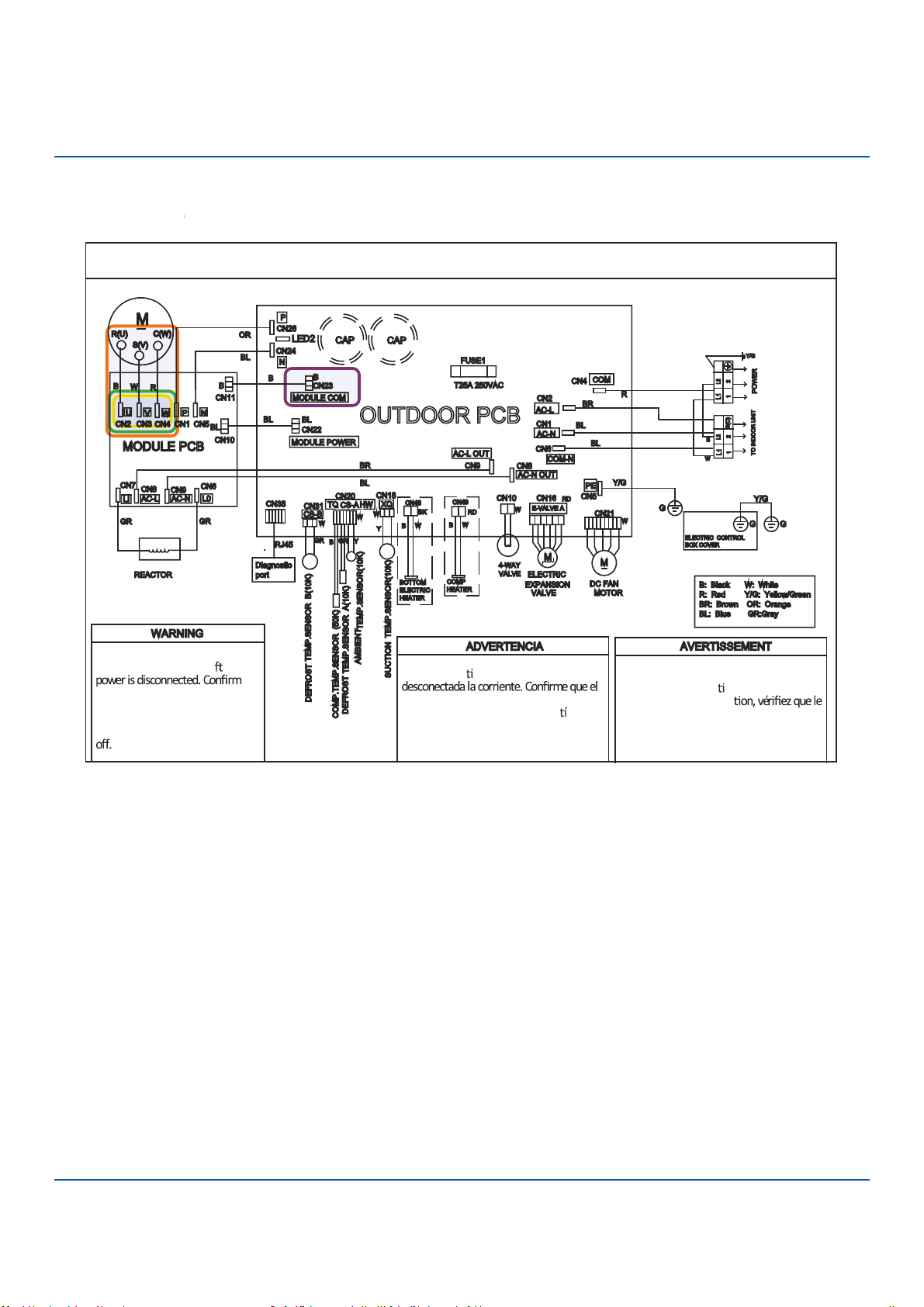
121
Troubleshooting
OUTDOOR UNIT WIRING DIAGRAM
COMPRESSOR
Electrical Shock Hazar
●
d
Capacitor retains charge a er
voltage at capacitor has dissipated
(<10V DC) with hand held voltmeter
before servicing. LED2 light
between CN24 and CN26 should be
Riesgo de Descarga Eléctrica
El capacitor re ene carga una vez
voltaje del capacitor se haya disipado (<10V
DC) apoyando la mano sobre el vol metro
antes de realizar el servicio técnico. La luz
LED2 que se encuentra entre CN24 y CN26
deberá estar apagada.
Risque de choc électrique
Le condensateur conserve sa charge après la
coupure de l’alimenta on électrique. Avant
de procéder à une répara
courant au condensateur s’est dissipé
(<10 VCC) à l’aide d’un voltmètre manuel. Le
voyant LED2 entre CN24 et CN26 doit être
éteint.
0011509127B
Error Code: F11/LED1: 18 Flash
Wiring Diag
r
am
R
e
f
e
f
f
r
en
c
e
ERROR CODES and Troubleshooting PAGE
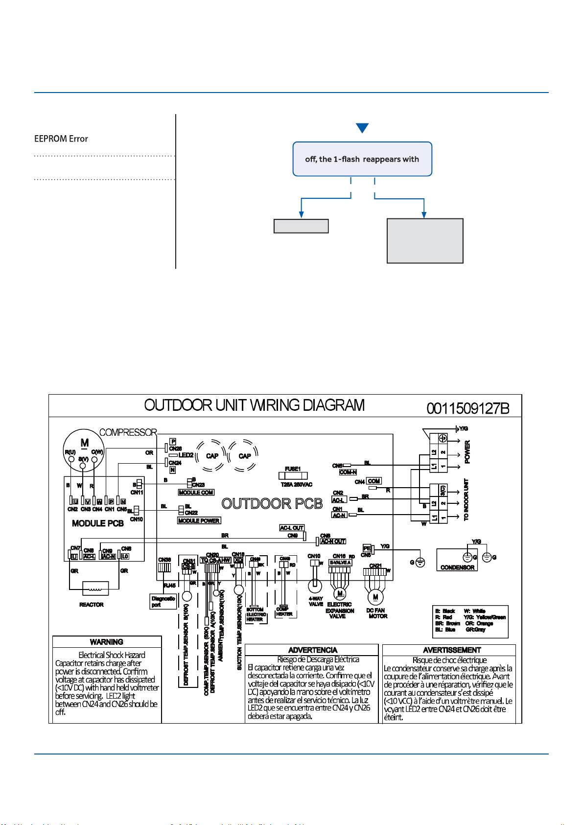
122
Troubleshooting
Start
S
●
ee reverse side for
wiring diagram and
relevant color-coded
test positions.
Yes No
The 10-minute
reboot has
corrected the
issue
Replace PCB
After 10 minutes with the power
power turned back on?
Error Code (Indoor/Outdoor)
F12/LED1: 1 Flash
Complete the “Check This First” Flow
Chart before continuing.
Models:
AW09TE2VHA
AW12TE2VHA
ASYW09CRDWA
ASYW12CRDWA
1U09TE2VHA
1U12TE2VHA
ASH109CRDWA
ASH112CRDWA
Wiring Diagram Reference
Outdoor Board Diagram
ERROR CODES and Troubleshooting
PAGE
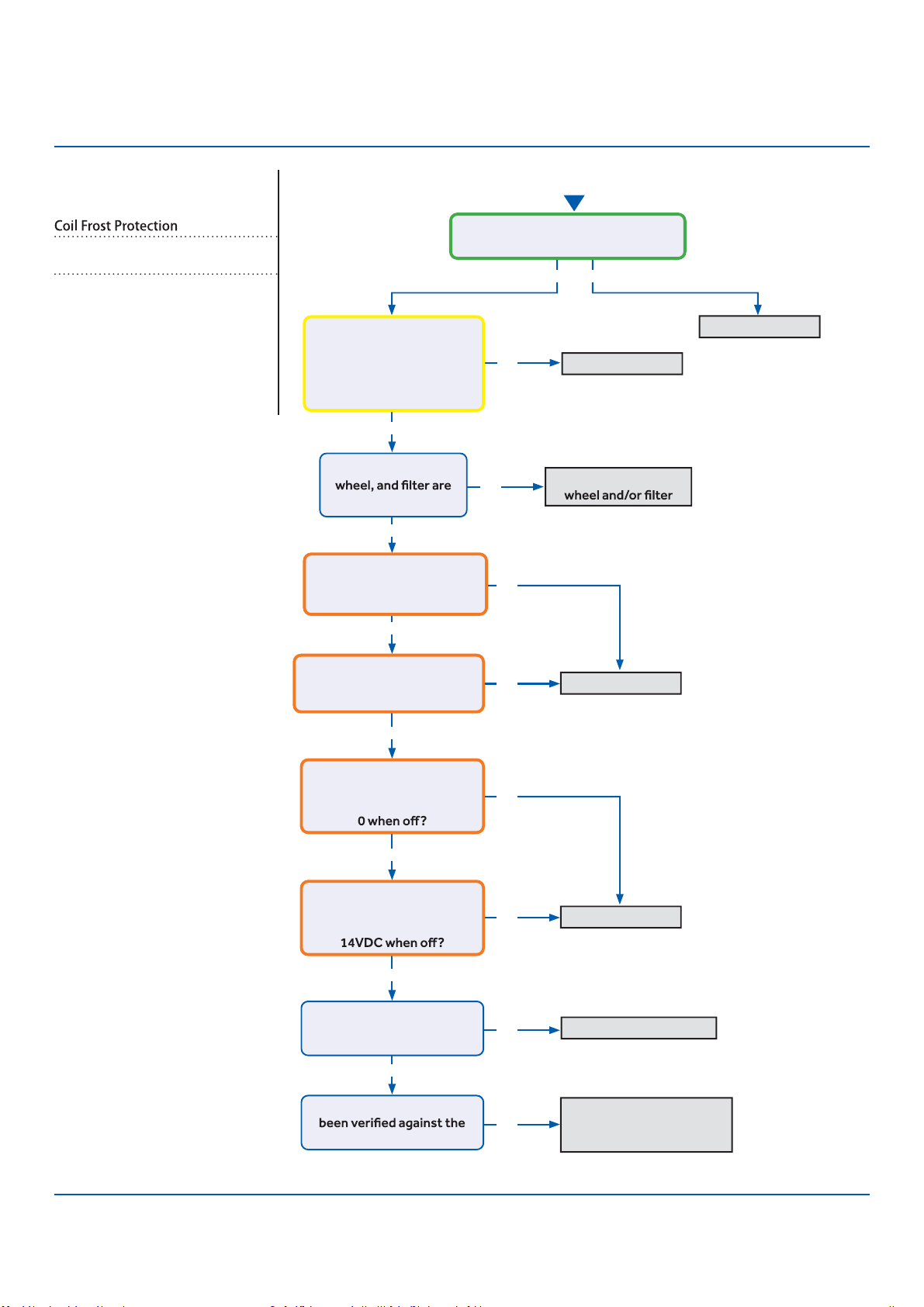
123
Troubleshooting
Start
See reverse side for
wiring diagram and
relevant color-coded
test positions.
Y
●
es
Y
●
es
Y
●
es
Yes
Y
●
es
Yes
Yes
No
No
No
No
No
No
No
No
Yes No
Replace PCB
Replace PCB
Replace Motor
Replace/Repair EEV Coil
Recover refrigerant, check
for leaks, evacuate, and
re-charge per nameplate
Replace sensor
Wash coil, blower
There is 5 VDC at CN6 on the Indoor
PCB across the black senor wires?
The Coil and Ambient
Sensors’ resistances are
within 3% of the value
listed in the Service Manual
sensor resistance table?
The coil, blower
free of dirt or debris?
There is DCV at the motor
PCB connections:
RD to BK: 310-334VDC?
There is DCV at the motor
PCB connections:
WH to BK: 15VDC
There is DCV at the motor
PCB connections:
YL to BK: 1-4VDC running,
There is DCV at the motor
PCB connections:
BL to BK: 4-8VDC running,
Is the EEV coil properly
seated and the coil
resistance correct?
The refrigerant charge has
nameplate value?
Error Code (Indoor/Outdoor)
E5/LED1: 22 Flash
Complete the “Check This First” Flow
Chart before continuing.
Models:
AW09TE2VHA
AW12TE2VHA
ASYW09CRDWA
ASYW12CRDWA
1U09TE2VHA
1U12TE2VHA
ASH109CRDWA
ASH112CRDWA
ERROR CODES and Troubleshooting PAGE
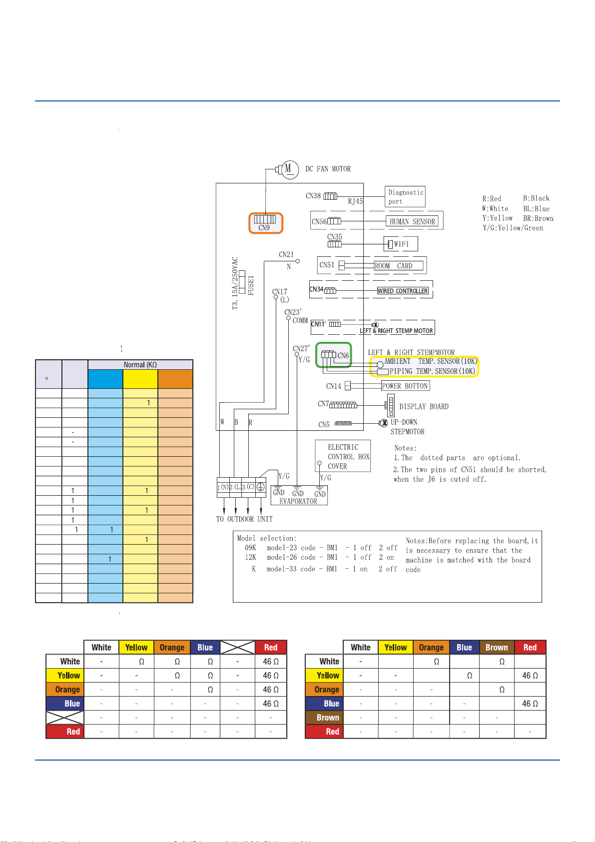
124
Troubleshooting
Error Code: E5/LED1: 22 Flash
●
Wiring Diag
r
am
R
e
f
e
f
f
r
en
c
e
Sensor
R
esi
s
tan
c
e
T
able
T
T
EEV
R
esi
s
tan
c
e
V
alues
V
V
EEV (6-pin, 6 wi
r
e)
EEV (6-pin, 5 wi
r
e)
ERROR CODES and Troubleshooting
07
18K model-36 code - BM1 - 1 off 2 off
PAGE
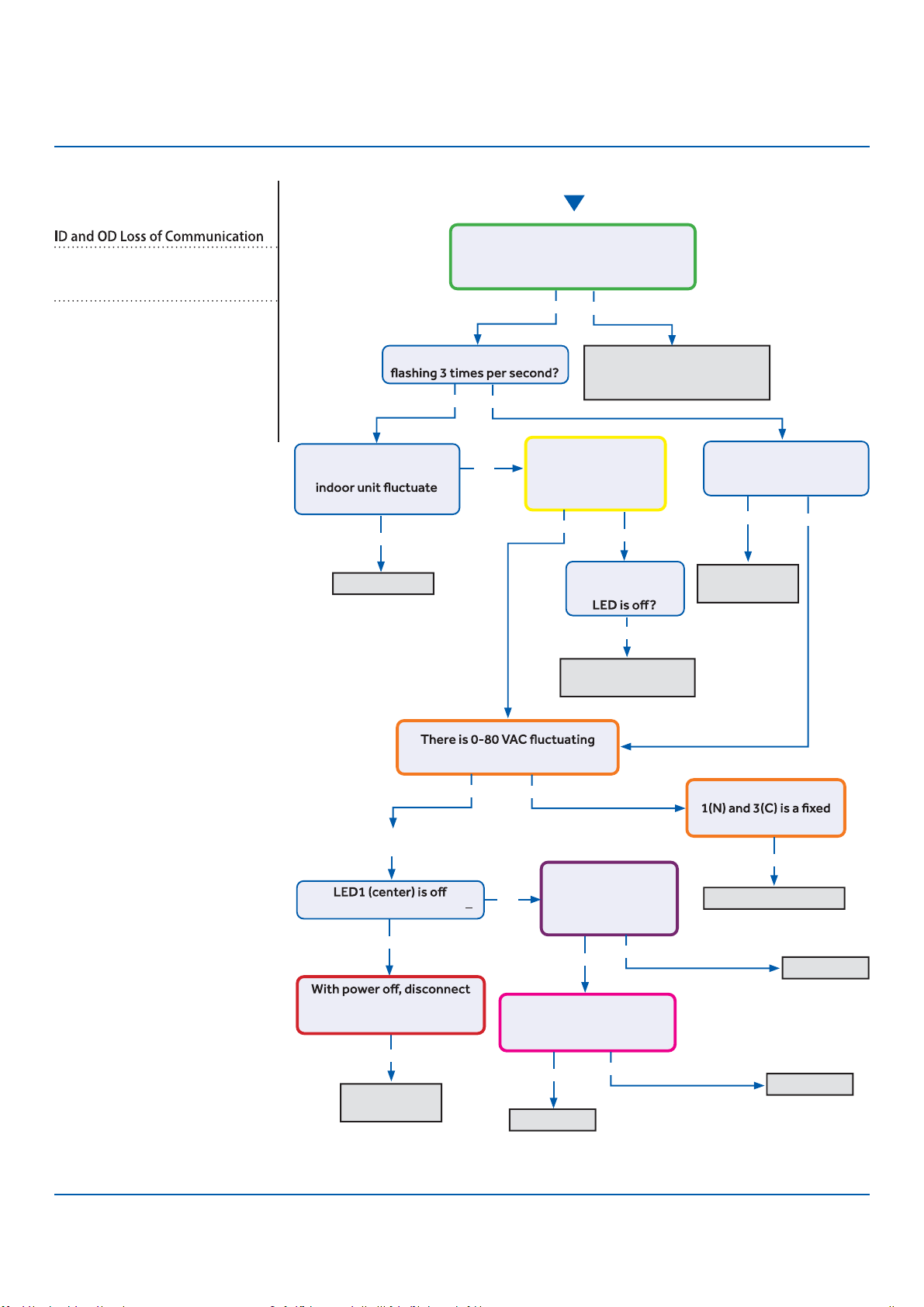
125
Troubleshooting
Start
See reverse side for
wiring diagram and
relevant color-coded
test positions.
R
●
eposition on correct
t
●
erminals, replace wire if
spliced or the incorrect type
Indoor PCB OK
●
The control wire is 14/4 stranded
copper on the correct terminals, with
no splices or loose connections?
Yes
No
Yes
Yes
No
No
Is the Indoor PCB LED
Does the voltage
between L and C at
0~140VAC?
Is the voltage from
L to C at indoor unit
between 0~80VAC
(approx..)?
Is the Indoor PCB LED
pattern repeatedly
Flash…Flash…On?
Fault is with
outdoor PCB
R
●
eplace fan
motor
Replace INDOOR PCB
Replace PCB
Replace PCB
Replace IPM
The communication
wire is broken
between 1(N) and 3(C) at ID UNIT?
There is 230 VAC
at the PCB? Across
AC-L OUT & AC-N
OUT (CN9 & CN8)
There is less than 5 VDC at
CN22 (module power) and
GND (pins 1 and 2)?
The voltage between
value at ID UNIT?
Go to outdoor PCB
No
Yes
Yes
Yes
Yes
Yes
Yes
Yes
No
No
Yes
Yes No
No
No
LED2 (upper left) is lighted?
fan motor at CN21. LED1
lights with power back on?
The display is
lighted, yet the
Error Code (Indoor/Outdoor)
E7/LED1: 15 Flash
Complete the “Check This First” Flow
Chart for both ID and OD units before
continuing.
Models:
AW09TE2VHA
AW12TE2VHA
ASYW09CRDWA
ASYW12CRDWA
1U09TE2VHA
1U12TE2VHA
ASH109CRDWA
ASH112CRDWA
ERROR CODES and Troubleshooting PAGE
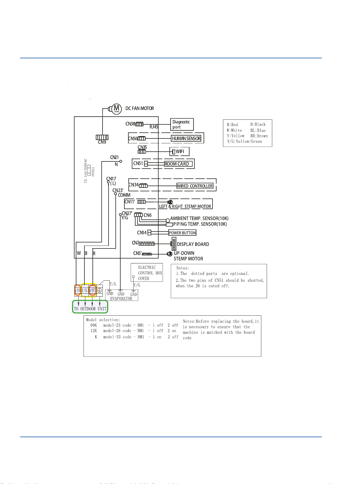
126
Troubleshooting
Error Code: E7/LED1: 15 Flash
Wiring Diag
r
am
R
e
f
e
f
f
r
en
c
e
ERROR CODES and Troubleshooting
07
18K model-36 code - BM1 - 1 off 2 off
PAGE
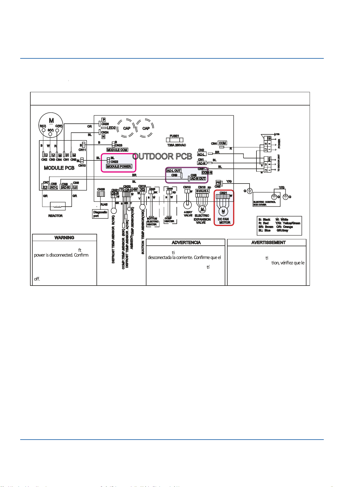
127
Troubleshooting
OUTDOOR UNIT WIRING DIAGRAM
COMPRESSOR
Electrical Shock Hazard
●
Capacitor retains charge a er
voltage at capacitor has dissipated
(<10V DC) with hand held voltmeter
before servicing. LED2 light
between CN24 and CN26 shoul
●
d be
Riesgo de Descarga Eléctrica
El capacitor re ene carga una vez
voltaje del capacitor se haya disipado (<10V
DC) apoyando la mano sobre el vol metro
antes de realizar el servicio técnico. La luz
LED2 que se encuentra entre CN24 y CN26
deberá estar apagada.
Risque de choc électrique
Le condensateur conserve sa charge après la
coupure de l’alimenta on électrique. Avant
de procéder à une répara
courant au condensateur s’est dissipé
(<10 VCC) à l’aide d’un voltmètre manuel. Le
voyant LED2 entre CN24 et CN26 doit être
éteint.
0011509127B
Error Code: E7/LED1: 15 Flash
Wiring Diag
r
am
R
e
f
e
f
f
r
en
c
e
ERROR CODES and Troubleshooting PAGE
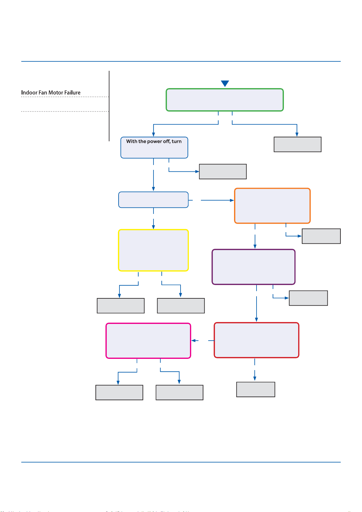
128
Troubleshooting
S
●
ee reverse side for
wiring diagram and
relevant color-coded
test positions.
Error Code (Indoor)
E14
Complete the “Check This First” F
●
low
Chart before continuing.
Models:
AW09TE2VHA
AW12TE2VHA
ASYW09CRDWA
●
ASYW12CRDWA
Yes
Yes
Y
●
es
Yes
No
Yes No
No
Fix incoming
power supply
Replace the fan
motor
Replace the main
board.
Replace the fan
motor
Replace the
main board.
Replace the
main board.
Replace the
main board.
Start
the fan by hand. Does it
move / rotate smootly?
Check the incoming voltage. Is it 208/230VAC
(+/- 10%) between L1/L2? 104/115VAC (+/-
10%) from L1 to GROUND and L2 to GROUND?
Re-apply power. Does the
fan come on and spin?
Measure DC voltage at fan
motor plug CN9 between
the Pin 7 (BLUE) and Pin
4 (BLACK) wire while
spinning the fan motor.
Does it generate 2~9VDC?
Measure DC voltage at fan
motor plug CN9 between Pin
1 (RED) and Pin 4 (BLACK).
Does it measure 300~380VDC
(+/-10%)?
Measure DC voltage at fan motor
plug CN9 between Pin 5 (WHITE)
and Pin 4 (BLACK).
Does it measure between
13.5-16.5VDC?
No
No
No
Yes
Replace the main
board.
Replace the fan
motor
Measure DC voltage at fan
motor plug CN9 between Pin 6
(YELLOW) and Pin 4 (BLACK).
Does it measure between
2-6VDC?
Measure DC voltage at fan motor
plug CN9 between the Pin 7
(BLUE) and Pin 4 (BLACK) wire
while spinning the fan motor.
Does it generate 2~9VDC?
No
Yes No
Yes
ERROR CODES and Troubleshooting
PAGE
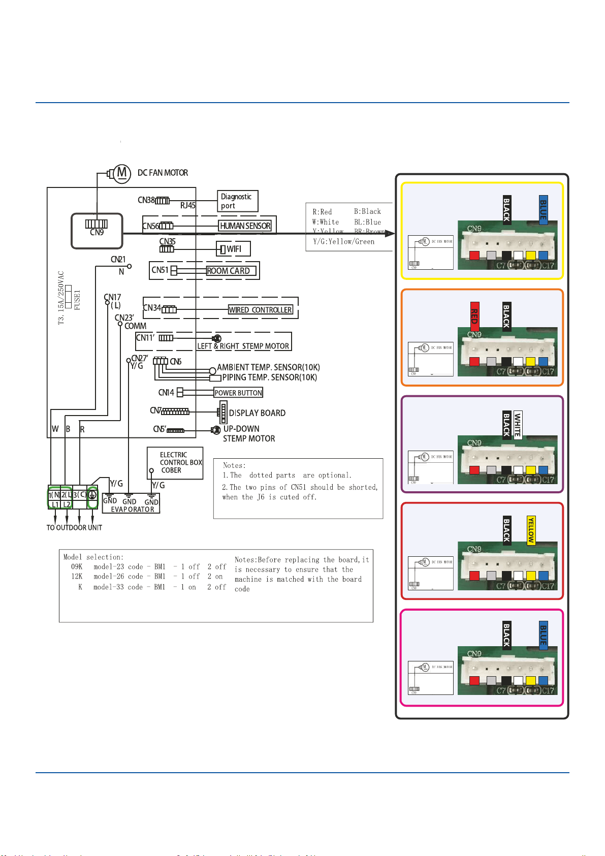
129
A
●
GE 43
Error Code: E14
Wiring Diag
r
am
R
e
f
e
f
f
r
en
c
e
A
GE 43
1
4
5 6/ 7
1
4
5 6/ 7
1
4
5 6/ 7
1
4
5 6/ 7
1
4
5 6/ 7
ERROR CODES and Troubleshooting
07
18K model-36 code - BM1 - 1 off 2 off
Troubleshooting
PAGE
130
Troubleshooting
Checking System Components
Checking Outdoor Unit Components
N
O
TE:
C
omponent resistance readings sh
o
wn in this section
are for reference only. Actual resistance values may
based on model being tested.
Component readings shown below are based on the models
of 1U*EH2VHD outdoor unit.
Step 3
Re-seat the plug on the connector at the conclusion of the
test.
Checking the EEV Coil
Step 1
Disconnect the EEV coil from the PCB for this test. Failure
to do so may provide inaccurate readings.
Step 2
The resistance values of plus pin combinations are 46 Ohm.
Step 3
Re-seat the plug on the connector at the conclusion of the
test.
Testing of the following components requires the use of
needle probes. Avoid testing the connector end of the plug,
as damage to the internal sections of the plug can occur.
Checking the Outdoor Unit Sensors
NOTE: Use respective temperature / sensor chart for sensor
type being tested.
Compressor discharge sensor
Suction sensor
Defrost temperature sensor
Ambient sensor
Step 1
Disconnect the sensor plug from the control board for this
test. Failure to do so may provide inaccurate readings.
Step 2
Using k-type temperature probe, determine the temperature
of the sensor being tested.
Step 3
Using an ohmmeter, check the resistance value of the sensor.
Step 4
Referring to the temperature / resistance table for the sensor
being checked, verify the resistance value corresponds to the
temperature checked in Step 2.
Replace the sensor if the reading is open, shorted, or outside
Step 5
Re-seat the plug on the connector at the conclusion of the
test.
Checking the Reversing Valve Coil
Step 1
Disconnect the reversing valve plug from the PCB
for this test. Failure to do so may provide inaccurate read-
ings.
Step 2
Using an ohmmeter, check the resistance value of the coil.
The resistance value of the coil should be 1.2 kilo ohms to
1.8 kilo ohms. Replace the valve c
ERROR CODES and Troubleshooting
Checking the DC Fan Motor
Step 1
Using needle probes, check the DCV at the back of the fan plug on
the PCB. The values are:
Red to black: +310 VDC
White to black: +15 VDC
Yellow to black: 1-4 VDC when running; 0 VDC when there is no call
for heating or cooling
Blue to black: pulsing 0-8 VDC when running; 14 VDC when there is
no call for heating or cooling
Checking the Compressor Windings
Step 1
Disconnect wiring from terminals U, V and W of the IPM.
Step 1
Using an Ohmmeter, check the resistance value of the
compressor windings. Measure between wires U and V,
U and W, and V, and W.
The resistance value of the windings should be balanced
(equal). If the resistance values are not equal, verify the
wiring and connections to the compressor as well as the
compressor itself. Repair or replace as needed.
PAGE
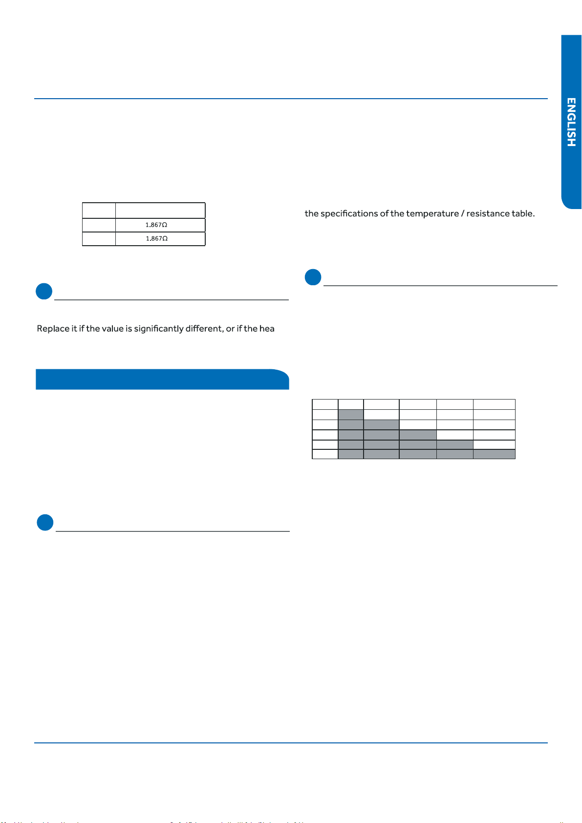
131
Troubleshooting
Step 3
Reconnect the wiring to the IPM at the conclusion of the
test.
NOTE: Resistance readings shown in this section are for
reference only
type being tested.
Coil sensor
Ambient sensor
Step 1
Disconnect the sensor from the PCB for this test. Failure to
do so may provide inaccurate readings.
Step 2
Determine the temperature of the sensor being tested.
Step 3
Check the resistance value of the sensor.
Step 4
Referring to the temperature / resistance table for the sensor
being checked, verify the resistance value corresponds to the
temperature checked in step 2.
Replace the sensor if the reading is open, shorted, or outside
Step 5
Re-seat the plug on the PCB at the conclusion of the test.
Checking the Up/Down Stepper Motor
Step 1
Disconnect the Up/Down Stepper Motor plug PCB for the test.
Failure to do so may provide inaccurate readings.
NOTE: When using the test probes, probe the back or side
contacts of the plug to obtain the reading. Do not try to
probe the connector end of the plug, as this may damage the
contacts.
Checking the Indoor Unit Sensors
NOTE: Use respective temperature / sensor chart for sensor
Testing of the following components requires the use of an
ohmmeter and k-type temperature probe.
Checking Indoor Unit Components
Checking the Base Pan Heater
The resistance across the heater should be 100 to 500 ohms.
ter
reads open or shorted.
Winding resistance
09K
12K
Model
ERROR CODES and Troubleshooting
Step 2
Refer to the chart shown below for plug pin combinations and
resistance values.
Step 3
Re-seat the plug on the connector at the conclusion of the
test.
Red Orange Yellow Pink Blue
Red 296.5Ohm 295.5 Ohm 296.3 Ohm 296.1 Ohm
Orange 594.5 Ohm 595.5 Ohm 594.5 Ohm
Yellow 594.3 Ohm 594.5 Ohm
Pink 594.3 Ohm
Blue
PAGE

Ambient, Defrost, and Pipe Sensor Tables
Discharge Sensor Tables
134
135
136
139
142
133PAGE
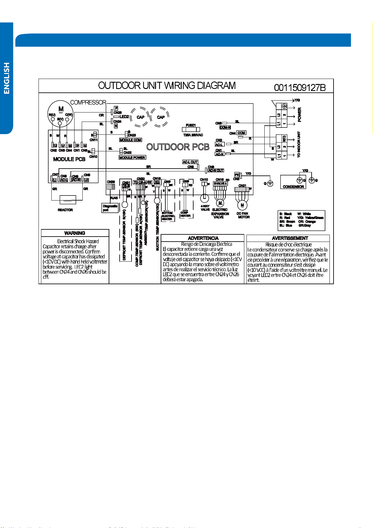
134
Outdoor Board Diagram
09K-12K
REFERENCE INFORMATION
PAGE
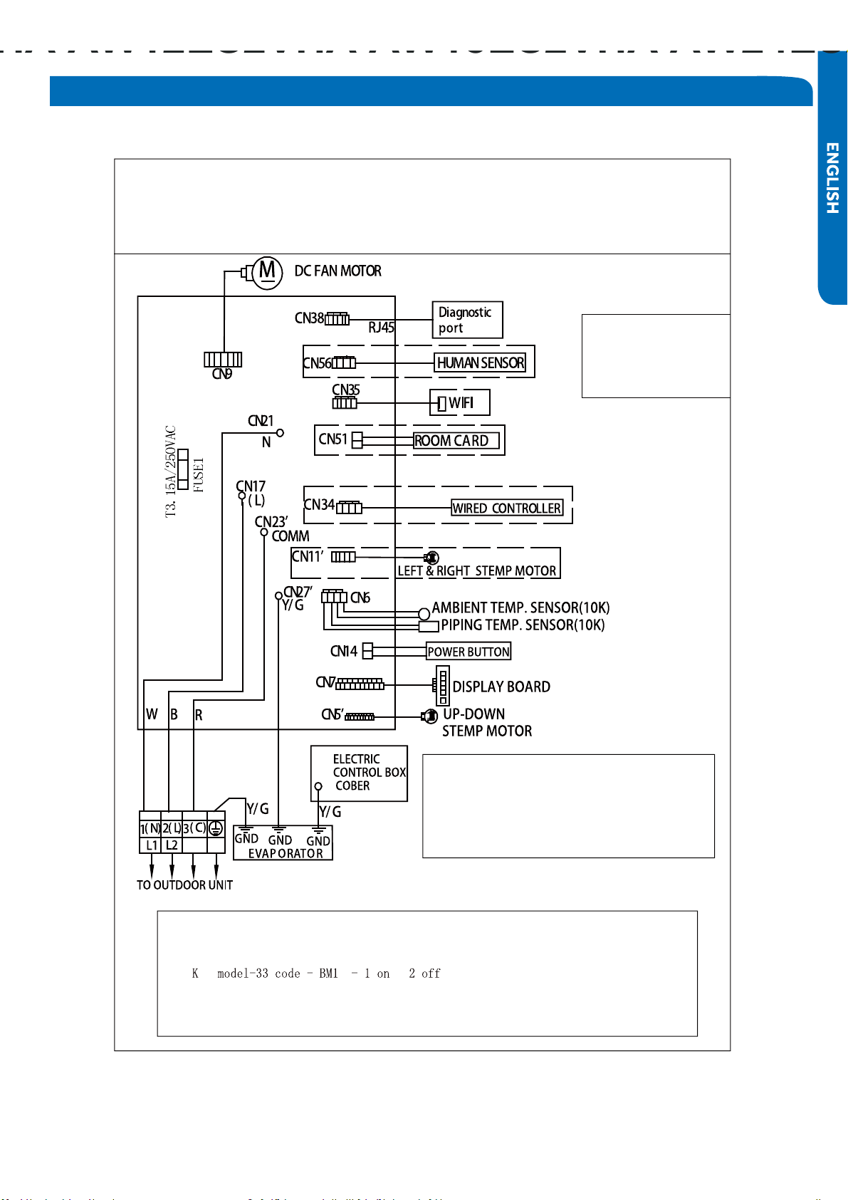
135
Indoor Board Diagram
R:Red
W:White
Y:Yellow
Y/G:Yellow/Green
B:Black
BR:Brown
BL:Blue
INDOOR UNIT DIAGRAM
Notes:
1.The dotted parts are optional.
2.The two pins of CN51 should be shorted,
when the J6 is cuted off.
Model selection:
09K model-23 code - BM1 - 1 off 2 off
12K model-26 code - BM1 - 1 off 2 on
Notes:Before replacing the board,it
is necessary to ensure that the
machine is matched with the board
code
0011509128A
REFERENCE INFORMATION
07
18K model-36 code - BM1 - 1 off 2 off
09K-12K
PAGE
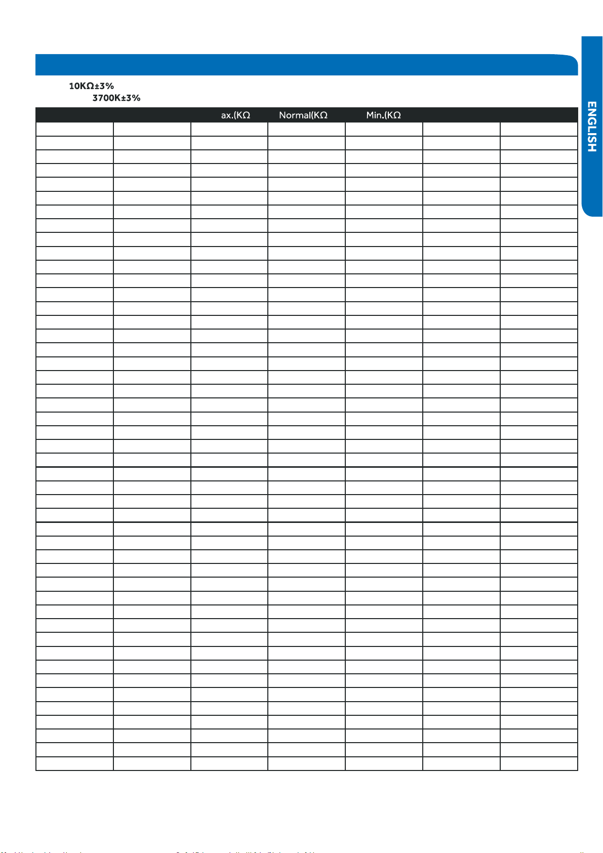
136
Room and Coil Sensor Tables
.pmeTF° .pmeT °C M ) ) ) Tolerance (°C)
-22 -30 165.217 147.9497 132.3678 -1.94 1.75
-20.2 -29
●
155.5754 139.56 125.0806 -1.93 1.74
-18.4 -28 146.5609 131.7022 118.2434 -1.91 1.73
-16.6 -27 138.1285 124.3392 111.8256 -1.89 1.71
-14.8 -26 130.2371 117.4366 105.7989 -1.87 1.7
-13
●
-25 122.8484 110.9627 100.1367 -1.85 1.69
-11.2 -24
●
115.9272 104.8882 94.8149 -1.83 1.67
-9.4 -23 109.441 99.1858 89.8106 -1.81 1.66
-7.6 -22 103.3598 93.8305 85.1031 -1.8 1.64
-5.8 -21 97.6556 88.7989 80.6728 -1.78 1.63
-4 -20 92.3028 84.0695 76.5017 -1.76 1.62
-2.2 -19 87.2775 79.6222 72.5729 -1.74 1.6
-0.4 -18 82.5577 75.4384 68.871 -1.72 1.59
1.4 -17 78.123 71.501 65.3815 -1.7 1.57
3.2 -16 73.9543 67.7939 62.0907 -1.68 1.55
5 -15 70.0342 64.3023 58.9863 -1.66 1.54
6.8 -14 66.3463 61.0123 56.0565 -1.64 1.52
8.6 -13 62.8755 57.911 53.2905 -1.62 1.51
10.4 -12
●
59.6076 54.9866 50.6781 -1.6 1.49
12.2 -11 56.5296 52.2278 48.2099 -1.58 1.47
14 -10 53.6294 49.6244 45.8771 -1.56 1.46
15.8 -9 50.8956 47.1666 43.6714 -1.54 1.44
17.6 -8 48.3178 44.8454 41.5851 -1.51 1.42
19.4 -7 45.886 42.6525 39.6112 -1.49 1.4
21.2 -6 43.5912 40.58 37.7429 -1.47 1.39
23 -5 41.4249 38.6207 35.9739 -1.45 1.37
24.8 -4 39.3792 36.7676 34.2983 -1.43 1.35
26.6 -3 37.4465 35.0144 32.7108 -1.41 1.33
28.4 -2 35.6202 33.3552 31.2062 -1.38 1.31
30.2 -1 33.8936 31.7844 29.7796 -1.36 1.29
32 0 32.2608 30.2968 28.4267 -1.34 1.28
33.8 1 30.7162 28.8875 27.1431 -1.32 1.26
35.6 2 29.2545 27.5519 25.925 -1.29 1.24
37.4 3 27.8708 26.2858 24.7686 -1.27 1.22
39.2 4 26.5605 25.0851 23.6704 -1.25 1.2
41 5 25.3193 23.9462 22.6273 -1.23 1.18
42.8 6 24.1432 22.8656 21.6361 -1.2 1.16
44.6 7 23.0284 21.8398 20.6939 -1.18 1.14
46.4 8 21.9714 20.8659 19.7982 -1.15 1.12
48.2 9 20.9688 19.9409 18.9463 -1.13 1.09
50 10 20.0176 19.0621 18.1358 -1.11 1.07
51.8 11 19.1149 18.227 17.3646 -1.08 1.05
53.6 12 18.258 17.4331 16.6305 -1.06 1.03
55.4 13 17.4442 16.6782 15.9315 -1.03 1.01
57.2 14 16.6711 15.9601 15.2657 -1.01 0.99
59 15
●
15.9366 15.277 14.6315 -0.98 0.96
60.8 16 15.2385 14.6268 14.0271 -0.96 0.94
R77° =
B77°/122° =
REFERENCE INFORMATION
PAGE
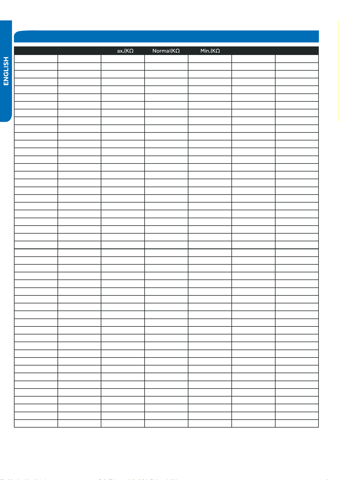
137
Room and Coil Sensor Tables
.pmeTF° .pmeT °C M ) ) ) Tolerance (°C)
62.6 17 14.5748 14.0079 13.451 -0.93 0.92
64.4 18 13.9436 13.4185 12.9017 -0.91 0.9
66.2 19 13.3431 12.8572 12.3778 -0.88 0.87
68 20 12.7718 12.3223 11.878 -0.86 0.85
69.8 21 12.228 11.8126 11.4011 -0.83 0.83
71.6 22 11.7102 11.3267 10.9459 -0.81 0.8
73.4 23 11.2172 10.8634 10.5114 -0.78 0.78
75.2 24 10.7475 10.4216 10.0964 -0.75 0.75
77 25 10.3 10 9.7 -0.75 0.75
78.8 26 9.8975 9.5974 9.298 -0.76 0.76
80.6 27 9.5129
●
9.2132 8.9148 -0.8 0.8
82.4 28 9.1454 8.8465 8.5496 -0.84 0.83
84.2 29 8.7942 8.4964 8.2013 -0.87 0.86
86 30 8.4583 8.1621 7.8691 -0.91 0.9
87.8 31 8.1371 7.8428 7.5522 -0.95 0.93
89.6 32 7.8299 7.5377 7.2498 -0.98 0.97
91.4 33 7.5359 7.2461 6.9611 -1.02 1
93.2 34 7.2546 6.9673 6.6854 -1.06 1.04
95 35 6.9852
●
6.7008 6.4222 -1.1 1.07
96.8 36 6.7273 6.4459 6.1707 -1.13 1.11
98.6 37 6.4803
●
6.2021 5.9304 -1.17 1.14
100.4
●
38 6.2437 5.9687 5.7007 -1.21 1.18
102.2 39 6.017 5.7454 5.4812 -1.25 1.22
104 40 5.7997 5.5316 5.2712 -1.29 1.25
105.8 41
●
5.5914 5.3269 5.0704 -1.33 1.29
107.6 42 5.3916 5.1308 4.8783 -1.37 1.33
109.4 43 5.2001 4.943 4.6944 -1.41 1.36
111.2 44 5.0163 4.763 4.5185 -1.45 1.4
113 45 4.84 4.5905 4.35 -1.49 1.44
114.8 46 4.6708 4.4252 4.1887 -1.53 1.47
116.6 47 4.5083 4.2666 4.0342 -1.57 1.51
118.4 48 4.3524 4.1145 3.8862 -1.61 1.55
120.2 49 4.2026 3.9686 3.7443 -1.65 1.59
122 50 4.0588 3.8287 3.6084 -1.7 1.62
123.8 51 3.9206 3.6943 3.478 -1.74 1.66
125.6 52 3.7878 3.5654 3.3531 -1.78 1.7
127.4 53 3.6601 3.4416 3.2332 -1.82 1.74
129.2 54 3.5374 3.3227 3.1183 -1.87 1.78
131 55 3.4195 3.2085 3.0079 -1.91 1.82
132.8 56 3.306 3.0989 2.9021 -1.95 1.85
134.6 57 3.1969 2.9935 2.8005 -2 1.89
136.4 58 3.0919 2.8922 2.7029 -2.04 1.93
138.2 59 2.9909 2.7948 2.6092 -2.08 1.97
140 60 2.8936 2.7012 2.5193 -2.13 2.01
141.8 61 2.8 2.6112 2.4328 -2.17 2.05
143.6 62 2.7099 2.5246 2.3498 -2.22 2.09
145.4 63 2.6232 2.4413 2.27 -2.26 2.13
147.2 64 2.5396 2.3611 2.1932 -2.31 2.17
REFERENCE INFORMATION PAGE
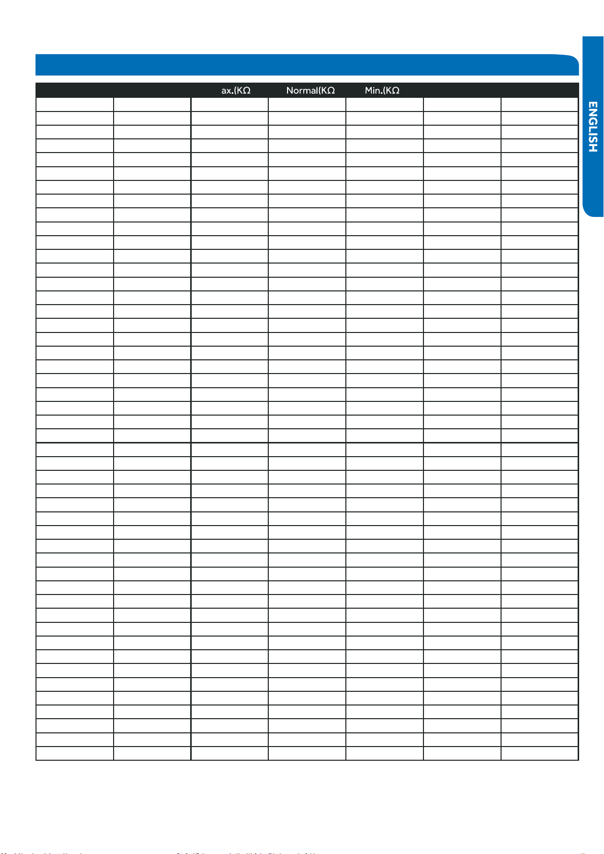
138 REFERENCE INFORMATION
Room and Coil Sensor Tables
.pmeTF° .pmeT °C M ) ) ) Tolerance (°C)
149 65
●
2.4591 2.284 2.1195 -2.36 2.21
150.8 66
●
2.3815 2.2098 2.0486 -2.4 2.25
152.6 67 2.3068 2.1383 1.9803 -2.45 2.29
154.4 68 2.2347 2.0695 1.9147 -2.49 2.34
156.2 69 2.1652 2.0032 1.8516 -2.54 2.38
158 70 2.0983 1.9393 1.7908 -2.59 2.42
159.8 71 2.0337 1.8778 1.7324 -2.63 2.46
161.6 72
●
1.9714 1.8186 1.6761 -2.68 2.5
163.4 73 1.9113 1.7614 1.6219 -2.73 2.54
165.2 74 1.8533 1.7064 1.5697 -2.78 2.58
167 75
●
1.7974 1.6533 1.5194 -2.83 2.63
168.8 76 1.7434 1.6021 1.471 -2.88 2.67
170.6 77 1.6913 1.5528 1.4243 -2.92 2.71
172.4 78 1.6409 1.5051 1.3794 -2.97 2.75
174.2 79 1.5923 1.4592 1.336 -3.02 2.8
176 80 1.5454 1.4149 1.2942 -3.07 2.84
177.8 81 1.5 1.3721 1.254 -3.12 2.88
179.6 82 1.4562 1.3308 1.2151 -3.17 2.93
181.4 83 1.4139 1.291 1.1776 -3.22 2.97
183.2 84 1.373 1.2525 1.1415 -3.27 3.01
185 85 1.3335 1.2153 1.1066 -3.32 3.06
186.8 86 1.2953 1.1794 1.073 -3.38 3.1
188.6 87 1.2583 1.1448 1.0405 -3.43 3.15
190.4 88 1.2226 1.1113 1.0092 -3.48 3.19
192.2 89 1.188 1.0789 0.9789 -3.53 3.24
194 90 1.1546 1.0476 0.9497 -3.58 3.28
195.8 91 1.1223 1.0174 0.9215 -3.64 3.33
197.6 92 1.091 0.9882 0.8942 -3.69 3.37
199.4 93 1.0607 0.9599 0.8679 -3.74 3.42
201.2 94 1.0314 0.9326 0.8424 -3.8 3.46
203 95 1.003 0.9061 0.8179 -3.85 3.51
204.8 96 0.9756 0.8806 0.7941 -3.9 3.55
206.6 97 0.949 0.8558 0.7711 -3.96 3.6
208.4 98 0.9232 0.8319 0.7489 -4.01 3.64
210.2 99 0.8983 0.8088 0.7275 -4.07 3.69
212 100 0.8741 0.7863 0.7067 -4.12 3.74
213.8 101
●
0.8507 0.7646 0.6867 -4.18 3.78
215.6 102 0.8281 0.7436 0.6672 -4.23 3.83
217.4 103 0.8061 0.7233 0.6484 -4.29 3.88
219.2 104 0.7848 0.7036 0.6303 -4.34 3.92
221 105 0.7641 0.6845 0.6127 -4.4 3.97
222.8 106 0.7441 0.6661 0.5957 -4.46 4.02
224.6 107 0.7247 0.6482 0.5792 -4.51 4.07
226.4 108 0.7059 0.6308 0.5632 -4.57 4.12
228.2 109 0.6877 0.614 0.5478 -4.63 4.16
230 110 0.67 0.5977 0.5328 -4.69 4.21
231.8 111 0.6528 0.582 0.5183 -4.74 4.26
233.6 112 0.6361 0.5667 0.5043 -4.8 4.31
PAGE
139
Room and Coil Sensor Tables
Ambient , Defrost and Pipe Sensor Tables
●
.pmeTF° .pmeT °C M ) ) ) Tolerance (°C)
235.4 113 0.62 0.5518 0.4907 -4.86 4.36
237.2 114 0.6043 0.5374 0.4775 -4.92 4.41
239 115 0.5891 0.5235 0.4648 -4.98 4.45
240.8 116 0.5743 0.51 0.4524 -5.04 4.5
242.6 117 0.56 0.4968 0.4404 -5.1 4.55
244.4 118 0.546 0.4841 0.4288 -5.16 4.6
246.2 119 0.5325 0.4717 0.4175 -5.22 4.65
248 120 0.5194 0.4597 0.4066 -5.28 4.7
.pmeTF° .pmeT °C M ) ) ) Tolerance (°C)
-22 -30 165.2170 147.9497 132.3678 -1.94 1.75
-20 -29 155.5754 139.5600 125.0806 -1.93 1.74
-18 -28 146.5609 131.7022 118.2434 -1.91 1.73
-17 -27 138.1285 124.3392 111.8256 -1.89 1.71
-15 -26 130.2371 117.4366 105.7989 -1.87 1.70
-13 -25 122.8484 110.9627 100.1367 -1.85 1.69
-11 -24 115.9272 104.8882 94.8149 -1.83 1.67
-9 -23 109.441
●
0 99.1858 89.8106 -1.81 1.66
-8 -22 103.3598 93.8305 85.1031 -1.80 1.64
-6 -21 97.6556 88.7989 80.6728 -1.78 1.63
-4 -20 92.3028 84.0695 76.5017 -1.76 1.62
-2 -19 87.2775 79.6222 72.5729 -1.74 1.60
0 -18 82.5577 75.4384 68.8710 -1.72 1.59
1 -17 78.1230 71.5010 65.3815 -1.70 1.57
3 -16 73.9543 67.7939 62.0907 -1.68 1.55
5 -15 70.0342 64.3023 58.9863 -1.66 1.54
7 -14 66.3463
●
61.0123 56.0565 -1.64 1.52
9 -13
●
62.8755 57.9110 53.2905 -1.62 1.51
10 -12 59.6076 54.9866 50.6781 -1.60 1.49
12 -11 56.5296 52.2278 48.2099 -1.58 1.47
14 -10 53.6294 49.6244 45.8771 -1.56 1.46
16 -9 50.8956 47.1666 43.6714 -1.54 1.44
18 -8 48.3178 44.8454 41.5851 -1.51 1.42
19 -7 45.8860 42.6525 39.6112 -1.49 1.40
21 -6 43.5912 40.5800 37.7429 -1.47 1.39
23 -5 41.4249 38.6207 35.9739 -1.45 1.37
25 -4 39.3792 36.7676 34.2983 -1.43 1.35
27 -3 37.4465 35.0144 32.7108 -1.41 1.33
28 -2 35.6202 33.3552 31.2062 -1.38 1.31
30 -1 33.8936 31.7844 29.7796 -1.36 1.29
32 0 32.2608 30.2968 28.4267 -1.34 1.28
34 1 30.7162 28.8875 27.1431 -1.32 1.26
36 2 29.2545 27.5519 25.9250 -1.29 1.24
37 3 27.8708 26.2858 24.7686 -1.27 1.22
39 4 26.5605 25.0851 23.6704 -1.25 1.20
41 5
●
25.3193 23.9462 22.6273 -1.23 1.18
43 6 24.1432 22.8656 21.6361 -1.20 1.16
REFERENCE INFORMATION PAGE

140 REFERENCE INFORMATION
Ambient , Defrost and Pipe Sensor Tables
.pmeTF° .pmeT °C M ) ) ) Tolerance (°C)
45 7 23.0284 21.8398 20.6939 -1.18 1.14
46 8 21.9714 20.8659 19.7982 -1.15 1.12
48 9 20.9688 19.9409 18.9463 -1.13 1.09
50 10 20.0176 19.0621 18.1358 -1.11 1.07
52 11 19.1149 18.2270 17.3646 -1.08 1.05
54 12 18.2580 17.4331 16.6305 -1.06 1.03
55 13
●
17.4442 16.6782 15.9315 -1.03 1.01
57 14 16.6711 15.9601 15.2657 -1.01 0.99
59 15
●
15.9366 15.2770 14.6315 -0.98 0.96
61 16 15.2385 14.6268 14.0271 -0.96 0.94
63 17 14.5748 14.0079 13.4510 -0.93 0.92
64 18 13.9436 13.4185 12.9017 -0.91 0.90
66 19 13.3431 12.8572 12.3778 -0.88 0.87
68 20 12.7718 12.3223 11.8780 -0.86 0.85
70 21 12.2280 11.8126 11.4011 -0.83 0.83
72 22
●
11.7102 11.3267 10.9459 -0.81 0.80
73 23 11.2172 10.8634 10.5114 -0.78 0.78
75 24 10.7475 10.4216 10.0964 -0.75 0.75
77 25 10.3000 10.0000 9.7000 -0.75 0.75
79 26 9.8975 9.5974 9.2980 -0.76 0.76
81 27 9.5129 9.2132 8.9148 -0.80 0.80
82 28 9.1454 8.8465 8.5496 -0.84 0.83
84 29 8.7942 8.4964 8.2013 -0.87 0.86
86 30 8.4583 8.1621 7.8691 -0.91 0.90
88 31 8.1371 7.8428 7.5522 -0.95 0.93
90 32 7.8299 7.5377 7.2498 -0.98 0.97
91 33 7.5359 7.2461 6.9611 -1.02 1.00
93 34 7.2546 6.9673 6.6854 -1.06 1.04
95 35 6.9852 6.7008 6.4222 -1.10 1.07
97 36 6.7273 6.4459 6.1707 -1.13 1.11
99 37 6.4803 6.2021 5.9304 -1.17 1.14
100 38 6.2437 5.9687 5.7007 -1.21 1.18
102 39 6.0170 5.7454 5.4812 -1.25 1.22
104 40 5.7997 5.5316 5.2712 -1.29 1.25
106 41 5.5914 5.3269 5.0704 -1.33 1.29
108 42
●
5.3916 5.1308 4.8783 -1.37 1.33
109 43 5.2001 4.9430 4.6944 -1.41 1.36
111 44 5.0163 4.7630 4.5185 -1.45 1.40
113 45 4.8400 4.5905 4.3500 -1.49 1.44
115 46 4.6708 4.4252 4.1887 -1.53 1.47
117 47 4.5083 4.2666 4.0342 -1.57 1.51
118 48 4.3524 4.1145 3.8862 -1.61 1.55
120 49 4.2026 3.9686 3.7443 -1.65 1.59
122 50 4.0588 3.8287 3.6084 -1.70 1.62
124 51 3.9206 3.6943 3.4780 -1.74 1.66
126 52
●
3.7878 3.5654 3.3531 -1.78 1.70
127 53 3.6601 3.4416 3.2332 -1.82 1.74
129 54 3.5374 3.3227 3.1183 -1.87 1.78
PAGE
141
REFERENCE INFORMATION
Ambient , Defrost and Pipe Sensor Tables
.pmeTF° .pmeT °C M ) ) ) Tolerance (°C)
131 55 3.4195 3.2085 3.0079 -1.91 1.82
133 56 3.3060 3.0989 2.9021 -1.95 1.85
135 57 3.1969 2.9935 2.8005 -2.00 1.89
136 58 3.0919 2.8922 2.7029 -2.04 1.93
138 59 2.9909 2.7948 2.6092 -2.08 1.97
140 60
●
2.8936 2.7012 2.5193 -2.13 2.01
142 61 2.8000 2.6112 2.4328 -2.17 2.05
144 62 2.7099 2.5246 2.3498 -2.22 2.09
145 63 2.6232
●
2.4413 2.2700 -2.26 2.13
147 64 2.5396 2.3611 2.1932 -2.31 2.17
149 65 2.4591 2.2840 2.1195 -2.36 2.21
151 66 2.3815 2.2098 2.0486 -2.40 2.25
153 67 2.3068 2.1383 1.9803 -2.45 2.29
154 68 2.2347
●
2.0695 1.9147 -2.49 2.34
156 69 2.1652 2.0032 1.8516 -2.54 2.38
158 70 2.0983 1.9393 1.7908 -2.59 2.42
160 71 2.0337 1.8778 1.7324 -2.63 2.46
162 72 1.9714 1.8186 1.6761 -2.68 2.50
163 73 1.9113 1.7614 1.6219 -2.73 2.54
165 74 1.8533 1.7064 1.5697 -2.78 2.58
167 75 1.7974 1.6533 1.5194 -2.83 2.63
169 76 1.7434 1.6021 1.4710 -2.88 2.67
171 77 1.6913 1.5528 1.4243 -2.92 2.71
172 78 1.6409 1.5051 1.3794 -2.97 2.75
174 79 1.5923
●
1.4592 1.3360 -3.02 2.80
176 80 1.5454 1.4149 1.2942 -3.07 2.84
178 81 1.5000 1.3721 1.2540 -3.12 2.88
180 82 1.4562 1.3308 1.2151 -3.17 2.93
181 83 1.4139 1.2910 1.1776 -3.22 2.97
183 84 1.3730 1.2525 1.1415 -3.27 3.01
185 85 1.3335 1.2153 1.1066 -3.32 3.06
187 86 1.2953 1.1794 1.0730 -3.38 3.10
189 87 1.2583 1.1448 1.0405 -3.43 3.15
190 88 1.2226 1.1113 1.0092 -3.48 3.19
192 89 1.1880 1.0789 0.9789 -3.53 3.24
194 90 1.1546 1.0476 0.9497 -3.58 3.28
196 91 1.1223 1.0174 0.9215 -3.64 3.33
198 92 1.0910 0.9882 0.8942 -3.69 3.37
199 93 1.0607 0.9599 0.8679 -3.74 3.42
201 94 1.0314 0.9326 0.8424 -3.80 3.46
203 95 1.0030 0.9061 0.8179 -3.85 3.51
205 96 0.9756 0.8806 0.7941 -3.90 3.55
207 97 0.9490 0.8558 0.7711 -3.96 3.60
208 98 0.9232 0.8319 0.7489 -4.01 3.64
210 99 0.8983 0.8088 0.7275 -4.07 3.69
212 100 0.8741 0.7863 0.7067 -4.12 3.74
214 101 0.8507 0.7646 0.6867 -4.18 3.78
216 102 0.8281 0.7436 0.6672 -4.23 3.83
(°C)
PAGE
142
Discharg
●
e Sensor Tables
Ambient , Defrost and Pipe Sensor Tables
.pmeTF° .pmeT °C M ) ) ) Tolerance(°C)
217 103 0.8061 0.7233 0.6484 -4.29 3.88
219 104 0.7848 0.7036 0.6303 -4.34 3.92
221 105 0.7641 0.6845 0.6127 -4.40 3.97
223 106 0.7441 0.6661 0.5957 -4.46 4.02
225 107 0.7247 0.6482 0.5792 -4.51 4.07
226 108 0.7059 0.6308 0.5632 -4.57 4.12
228 109 0.6877 0.6140 0.5478 -4.63 4.16
230 110 0.6700 0.5977 0.5328 -4.69 4.21
232 111 0.6528 0.5820 0.5183 -4.74 4.26
234 112 0.6361 0.5667 0.5043 -4.80 4.31
235 113 0.6200 0.5518 0.4907 -4.86 4.36
237 114 0.6043 0.5374 0.4775 -4.92 4.41
239 115 0.5891 0.5235 0.4648 -4.98 4.45
241 116 0.5743 0.5100 0.4524 -5.04 4.50
243 117 0.5600 0.4968 0.4404 -5.10 4.55
244 118 0.5460 0.4841 0.4288 -5.16 4.60
246 119 0.5325 0.4717 0.4175 -5.22 4.65
248 120 0.5194 0.4597 0.4066 -5.28 4.70
Temp.(°F) Temp.(°C) M ) ) ) Tolerance
-22 -30
●
14646.0505 12061.7438 9924.4999 -2.96 2.45
-20.2 -29 13654.1707 11267.873 9290.2526 -2.95 2.44
-18.4 -28 12735.8378 10531.3695 8700.6388 -2.93 2.44
-16.6 -27 11885.1336 9847.724 8152.2338 -2.92 2.43
-14.8 -26 11096.6531 9212.8101 7641.8972 -2.91 2.42
-13 -25 10365.4565 8622.8491 7166.7474 -2.9 2.42
-11.2 -24 9687.027 8074.3787 6724.1389 -2.88 2.41
-9.4 -23 9057.2314 7564.2244 6311.6413 -2.87 2.41
-7.6
●
-22 8472.2852 7089.4741 5927.0206 -2.86 2.4
-5.8 -21
●
7928.7217 6647.4547 5568.2222 -2.84 2.39
-4 -20
●
7423.3626 6235.7109 5233.3554 -2.83 2.39
-2.2 -19 6953.293 5851.9864 4920.6791 -2.82 2.38
-0.4 -18 6515.8375 5494.2064 4628.5894 -2.8 2.37
1.4 -17 6108.5393 5160.4621 4355.6078 -2.79 2.37
3.2 -16 5729.1413 4848.9963 4100.3708 -2.77 2.36
5 -15 5375.5683 4558.1906 3861.6201 -2.76 2.35
6.8 -14 5045.9114 4286.5535 3638.1938 -2.75 2.34
8.6 -13 4738.4141 4032.7098 3429.0191 -2.73 2.34
10.4 -12 4451.4586 3795.391 3233.1039 -2.72 2.33
12.2 -11 4183.5548 3573.426 3049.5312 -2.7 2.32
14 -10 3933.3289 3365.7336 2877.4527 -2.69 2.31
15.8 -9 3699.5139 3171.3148 2716.0828 -2.67 2.3
17.6 -8 3480.9407 2989.246 2564.6945 -2.66 2.29
19.4 -7 3276.5302 2818.6731 2422.6139 -2.64 2.28
21.2 -6 3085.2854 2658.8058 2289.2164 -2.63 2.28
23 -5 2906.2851 2508.9126 2163.923 -2.61 2.27
R176° =
B77°/176° =
REFERENCE INFORMATION
PAGE
143
REFERENCE INFORMATION
Discharge Sensor Tables
Temp.(°F) Temp.(°C) M ) ) ) Tolerance
24.8 -4 2738.6777 2368.3158 2046.1961 -2.6 2.26
26.6 -3 2581.6752 2236.3876 1935.5371 -2.58 2.25
28.4 -2 2434.5487 2112.5459 1831.4826 -2.56 2.24
30.2 -1 2296.62
●
3 1996.2509 1733.6024 -2.55 2.23
32 0 2167.273 1887.0018 1641.4966 -2.53 2.22
33.8 1 2045.9191 1784.3336 1554.7931 -2.52 2.21
35.6 2 1932.024
●
2 1687.8144 1473.146 -2.5 2.2
37.4 3 1825.0899 1597.0431 1396.2333 -2.48 2.19
39.2 4 1724.654 1511.6468 1323.7551 -2.47 2.17
41 5 1630.28
●
7 1431.2787 1255.4324 -2.45 2.16
42.8 6 1541.5904 1355.6163 1191.0048 -2.43 2.15
44.6 7 1458.1938 1284.3593 1130.2298 -2.41 2.14
46.4 8 1379.7528 1217.2282 1072.8813 -2.4 2.13
48.2 9 1305.9472 1153.9626 1018.7481 -2.38 2.12
50 10 1236.4792 1094.32 967.6334 -2.36 2.11
51.8 11 1171.0715 1038.0743 919.3533 -2.35 2.09
53.6 12 1109.4661 985.0146 873.7359 -2.33 2.08
55.4 13 1051.4226 934.944 830.621 -2.31 2.07
57.2 14 996.7169 887.6792 789.8583 -2.29 2.06
59 15 945.1404 843.0486 751.3077 -2.27 2.04
60.8 16 896.498
●
1 800.8922 714.838 -2.26 2.03
62.6 17 850.6086 761.0603 680.3265 -2.24 2.02
64.4 18 807.3024 723.4134 647.658 -2.22 2
66.2 19 766.4212 687.8205 616.7252 -2.2 1.99
68 20 727.8172 654.1596 587.4271 -2.18 1.98
69.8 21 691.3524 622.3161 559.6694 -2.16 1.96
71.6 22 656.8979 592.1831 533.3634 -2.14 1.95
73.4 23 624.3328 563.6604 508.4261 -2.12 1.93
75.2 24 593.5446 536.654 484.7796 -2.1 1.92
77 25 564.4275 511.076 462.351 -2.09 1.9
78.8 26 536.9865 486.9352 441.1516 -2.07 1.89
80.6 27 511.0105 464.05 421.0258 -2.05 1.87
82.4 28 486.4151 442.3499 401.9146 -2.03 1.86
84.2 29 463.1208 421.7683 383.7626 -2.01 1.84
86 30 441.0535 402.243 366.5175 -1.99 1.83
87.8 31 420.1431 383.7151 350.1301 -1.97 1.81
89.6 32 400.3242 366.1295 334.5542 -1.95 1.8
91.4 33 381.53
●
5 349.4341 319.746 -1.93 1.78
93.2 34 363.7176 333.5801 305.6645 -1.9 1.76
95 35 346.8176 318.5216 292.2709 -1.88 1.75
96.8 36 330.7839 304.2151 279.5286 -1.86 1.73
98.6 37 315.5682 290.6199 267.4031 -1.84 1.71
100.4 38 301.1254 277.6976 255.862 -1.82 1.7
102.2 39 287.4128 265.4119 244.8745 -1.8 1.68
104 40 274.3905 253.7288 234.4118 -1.78 1.66
105.8 41 262.0206 242.6161 224.4465 -1.76 1.64
107.6 42 250.2676 232.0436 214.9529 -1.74 1.63
109.4 43 239.0983 221.9825 205.9065 -1.71 1.61
111.2 44 228.4809 212.406 197.2844 -1.69 1.59
PAGE
144
Discharge Sensor Tables
Temp.(°F) Temp.(°C) M ) ) ) Tolerance
113 45 218.386 203.2887 189.0648 -1.67 1.57
114.8 46 208.7855 194.6066 181.2273 -1.65 1.55
116.6 47
●
199.6531 186.3369 173.7524 -1.63 1.54
118.4 48 190.9639 178.4584 166.6217 -1.6 1.52
120.2 49 182.6945 170.9508 159.8181 -1.58 1.5
122 50 174.8228 163.7951 153.3249 -1.56 1.48
123.8 51 167.328 156.9733 147.1268 -1.53 1.46
125.6 52 160.1904 150.4683 141.209 -1.51 1.44
127.4 53 153.3914 144.2641 135.5577 -1.49 1.42
129.2 54 146.9136 138.3454 130.1598 -1.47 1.4
131 55 140.7403 132.698 125.0027 -1.44 1.38
132.8 56 134.8559 127.3081 120.0746 -1.42 1.36
134.6 57 129.2457 122.163 115.3645 -1.4 1.34
136.4 58 123.8956 117.2504 110.8618 -1.37 1.32
138.2 59 118.7926 112.5589 106.5564 -1.35 1.3
140 60 113.9241 108.0776 102.4388 -1.32 1.28
141.8 61 109.2784 103.7961 98.5 -1.3 1.26
143.6 62 104.8443 99.7046 94.7315 -1.28 1.23
145.4 63 100.6112 95.7939 91.1253 -1.25 1.21
147.2 64 96.5692 92.0553 87.6735 -1.23 1.19
149 65 92.7088 88.4805 84.369 -1.2 1.17
150.8 66 89.0211 85.0614 81.2048 -1.18 1.15
152.6 67 85.4976 81.7908 78.1744 -1.15 1.12
154.4 68 82.1303 78.6615 75.2715 -1.13 1.1
156.2 69 78.9116 75.6668 72.4902 -1.1 1.08
158 70 75.8343 72.8004 69.8249 -1.08 1.06
159.8 71 72.8916 70.0561 67.2703 -1.05 1.03
161.6 72 70.077 67.4283 64.8213 -1.03 1.01
163.4 73 67.3844 64.9115 62.4731 -1 0.99
165.2 74 64.808 62.5006 60.2211 -0.98 0.96
167 75 62.3423 60.1906 58.0609 -0.95 0.94
168.8 76 59.9821 57.977 55.9885 -0.92 0.92
170.6 77 57.7223 55.8552 53.9998 -0.9 0.89
172.4 78 55.5583 53.821 52.0912 -0.87 0.87
174.2 79 53.4856 51.8706 50.2591 -0.85 0.84
176 80 51.5 50 48.5 -0.85 0.84
177.8 81
●
49.7063 48.2057 46.7083 -0.85 0.85
179.6 82
●
47.9835 46.4842 44.9911 -0.89 0.89
181.4 83 46.3286 44.8323 43.3452 -0.93 0.92
183.2 84 44.7385 43.2468 41.7672 -0.96 0.95
185 85 43.2105 41.7248 40.254 -1 0.99
186.8 86 41.7386 40.2604 38.7996 -1.03 1.02
188.6 87
●
40.3241 38.8545 37.4048 -1.07 1.06
190.4 88 38.9643 37.5045 36.0668 -1.11 1.09
192.2 89 37.6569 36.2078 34.7831 -1.14 1.13
194 90 36.3996 34.9622 33.5513 -1.18 1.16
195.8 91
●
35.1903 33.7653 32.3689 -1.22 1.19
197.6 92 34.0269 32.6151 31.2338 -1.26 1.23
199.4 93 32.9075 31.5096 30.1438 -1.3 1.27
REFERENCE INFORMATION
PAGE

145
Discharge Sensor Tables
Temp.(°F) Temp.(°C) M ) ) ) Tolerance
201.2 94 31.8302 30.4467 29.097 -1.33 1.3
203 95 30.7933 29.4246 28.0915 -1.37 1.34
204.8 96 29.795 28.4417 27.1254 -1.41 1.37
206.6 97 28.8337 27.4961 26.197 -1.45 1.41
208.4 98 27.9078 26.5864 25.3048 -1.49 1.44
210.2
●
99 27.016 25.711 24.447 -1.53 1.48
212 100 26.1569 24.8685 23.6222 -1.57 1.52
213.8 101 25.329 24.0574 22.8291 -1.61 1.55
215.6 102 24.5311 23.2765 22.0662 -1.65 1.59
217.4 103 23.762 22.5245 21.3323 -1.69 1.63
219.2 104 23.0205 21.8002 20.6261 -1.73 1.66
221 105 22.3055 21.1025 19.9465 -1.77 1.7
222.8 106 21.6159 20.4303 19.2924 -1.81 1.74
224.6 107 20.9508
●
19.7825 18.6626 -1.85 1.77
226.4 108 20.3091
●
19.1582 18.0563 -1.89 1.81
228.2 109 19.6899 18.5564 17.4723 -1.93 1.85
230 110 19.0924
●
17.9761 16.9098 -1.98 1.89
231.8 111 18.5157 17.4166 16.368 -2.02 1.93
233.6 112 17.959 16.8769 15.8458 -2.06 1.96
235.4 113 17.4214 16.3564 15.3427 -2.1 2
237.2 114 16.9023 15.8542 14.8577 -2.15 2.04
239 115 16.401 15.3696 14.3902 -2.19 2.08
240.8 116 15.9167 14.902 13.9394 -2.23 2.12
242.6 117 15.4489 14.4506 13.5047 -2.27 2.16
244.4 118 14.9968 14.0149 13.0855 -2.32 2.19
246.2 119 14.5599 13.5942 12.6811 -2.36 2.23
248 120 14.1376 13.1879 12.2909 -2.41 2.27
249.8 121 13.7294 12.7955 11.9144 -2.45 2.31
251.6 122 13.3347 12.4165 11.551 -2.5 2.35
253.4 123 12.9531 12.0503 11.2003 -2.54 2.39
255.2 124 12.584 11.6965 10.8617 -2.58 2.43
257 125 12.227
●
11.3545 10.5348 -2.63 2.47
258.8 126 11.8817 11.024 10.2191 -2.68 2.51
260.6 127 11.5475 10.7046 9.9142 -2.72 2.55
262.4 128 11.2242 10.3957 9.6197 -2.77 2.59
264.2 129 10.9112 10.097 9.3352 -2.81 2.63
266 130 10.6084 9.8082 9.0602 -2.86 2.67
267.8 131 10.3151 9.5288 8.7945 -2.91 2.71
269.6 132 10.0312 9.2586 8.5378 -2.95 2.75
271.4 133 9.7563 8.9971 8.2895 -3 2.8
273.2 134 9.4901 8.7441 8.0495 -3.05 2.84
275 135 9.2322 8.4993 7.8175 -3.09 2.88
276.8 136 8.9824 8.2623 7.5931 -3.14 2.92
278.6 137 8.7404 8.0329 7.376 -3.19 2.96
280.4 138 8.5059 7.8108 7.166 -3.24 3
282.2 139 8.2787 7.5958 6.9629 -3.29 3.04
284 140 8.0584 7.3875 6.7664 -3.33 3.09
REFERENCE INFORMATION PAGE

www.geappliances.comGE Appliances, A Haier CompanyAppliance Park, Louisville, KY 40225©2021 GE Appliances, A Haier CompanyRevision Date: March 2021AW09TE1VHAAW12TE1VHAAW09TE2VHAAW12TE2VHAAW18TE2VHAAW24TE2VHAASYW09CRAWAASYW12CRAWAASYW09CRDWAASYW12CRDWAASYW18CRDWAASYW24CRDWA1U09TE1VHA 1U12TE1VHA1U09TE2VHA1U12TE2VHA 1U18TE2VHA 1U24TE2VHAASH109CRAWA ASH112CRAWA ASH118CRDWA ASH124CRDWAModel #'s