
www.PyleUSA.com
2
WARNING:
• For your own safety, please read and understand these
warnings and keep this user guide for future reference.
• Always make sure the cart is fully extended and locked
before use. Always make sure the cart is folded and locked
properly before lifting or transporting.
• Do not run while using this product.
• Do not use accessories other than those designed for use
with your cart.
• Keep all packing materials away from children and recycle
where possible or where required by law.
MAINTENANCE
• To clean the trolley, wipe with a soft, dry cloth.
• Car polish may be used to maintain nish.
• Lubricate moving parts every 6 months.
WARNING:
• Keep hands and ngers away from moving or sliding parts!
• Always keep control of the Golf Push Cart -
Do not let it run down hills without full control.

PARTS LIST
A Foam handle
B Umbrella holder base
C Scorecard holder
D Handle tube
E Upper joint
F Upper bag bracket
G Seat
H Upper frame
I Lower frame
J Left wheel mechanism lock
J1 Right wheel mechanism lock
K Footbrake
L Lower bag bracket
M Front wheel
N Fixing strap
O Umbrella holder storage rack
P Rear wheel
www.PyleUSA.com
3
J1
N
I
J
K
O
D
G
A
B
C
E
F
H
P
L
M

ASSEMBLY INSTRUCTIONS
Assembly rear wheel sets insert the wheel holes
then press the buckle towards down as Fig. 1.
www.PyleUSA.com
4
Assemble the front wheel set as Fig. 2.
Open the xing strap and buckle
to unfold the cart as Fig. 3.
Put the seat on the frame bar as Fig. 4.
Fig. 1
buckle buckle
Fig. 2
buckle
Fig. 3
Fig. 4

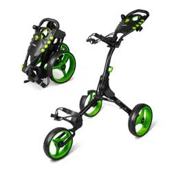
FOLDING STEPS
USING THE FOOT BRAKE SWIVEL FRONT WHEEL INSTRUCTION
www.PyleUSA.com
5
Remove the seat from
frame bar as Fig. 5.
Fix the velcro strap around the upper
and lower frame as shown Fig. 8.
Press the button to take o
the front wheel as Fig. 6.
Push down brake pedal to stop the rear wheel
and raise up to release the rear wheel as Fig. 9.
The buckle can move from the front to the back as Fig. 10. The wheel can
swivel when the buckle is on the "A" position as Fig.11, and the wheel
can go straight line when the buckle is on the "B" position as Fig.12.
Fig. 5
Buckle
A
B
Button
Buckle
Fig. 6
Fig. 7
Fig. 8
Release the buckle, fold
the upper frame and the
handle per the drawing
position as Fig. 7.
Fig. 9
Fig. 10
Fig. 11
Fig. 12

www.PyleUSA.com
6
FRONT WHEEL ADJUSTABLE STRAIGHT SYSTEM
WHEN FACING THE CART
If the cart veers to RIGHT: Use the Allen wrench (as shown in Fig. 2) to lose the 2 screws (A) on the backside of the
front wheel frame as shown in Fig. 3. Then adjust the front wheel to center position by turning the screw (B) counter-
clockwise as in Fig. 4. Tighten the 2 Screws (A) after the front wheel alignment is done.
If the cart veers to LEFT: Use the Allen wrench (as shown in Fig. 2) to lose the 2 screws (A) on the backside of the front
wheel frame as shown in Fig. 3. Then adjust the front wheel to center position by turning the screw (B) clockwise as in
Fig. 4. Tighten the 2 Screws (A) after the front wheel alignment is done.
A
B
Left
Right
Fig. 1 Fig. 3Fig. 2 Fig. 4
Allen wrench

FEATURES:
• New Deluxe Scorecard Holder
• Upper and Lower Bracket with Strap
• Foam Handle Grip
• Ergonomic Padded Adjustable Handle
• Includes Scorecard Holder, and Patented Bag Holder
• Simple Quick Braking System
• Durable and Compact Size for Easy Storage and Transportation
• Easy to Fold and Unfold
• Designed for Multiple Pushing Positions
WHAT'S IN THE BOX:
• (1) 3-Wheel Golf Push Cart
TECHNICAL SPECS:
• Construction Material: Steel Frame
• Max. Load Capacity: 33.1 lbs.
• Front Wheel Size: 9.5'' -inches
• Rear Wheels Size: 11.5'' -inches
• Folded Product Dimension (L x W x H): 23.6" x 38" x 15.2" -inches
• Unfolded Product Dimension (L x W x H): 23.6" x 56.6" x 44.1" -inches
www.PyleUSA.com
7

Questions? Comments?
We are here to help!
Phone: (1) 718-535-1800
Email: support@pyleusa.com